

Sony DWR-R02DN Operating Instructions Manual

Digital Wireless
4-585-175-01 (1)
Receiver
Operating Instructions
DWR-R02DN
© 2015 Sony Corporation

Table of Contents
Features .......................................................4
Parts Identification......................................6
Front Panel.................................................... 6
Rear Panel..................................................... 9
Preparation ................................................11
Rack Mounting ........................................... 11
System Configuration Examples .............12
Using the Supplied Antennas...................... 12
Configuration Example of Multi-Channel
System ............................................... 14
Configuration Example of ST Remote
System ............................................... 17
Configuration Example of NT Remote
System ............................................... 18
Setting the Receiving Channel.................19
Selecting the Band Block............................ 19
Selecting the Frequency Band .................... 19
Selecting the Group/Channel...................... 19
Using the Active Channel Scan Function... 20
Using the Clear Channel Scan Function..... 20
Using the Encrypted Transmission
Function ..............................................21
Using Secure Key Mode
(SECURE KEY)................................ 21
Using Password Mode (PASSWORD)....... 22
Setting the Audio Codec Mode ................22
Menu Displays and Detailed Settings......23
Menu Structure and Hierarchy.................... 23
Basic Menu Operations............................... 23
RECEIVER Menu........................................24
Frequency band setting (BAND) ................ 24
Group/channel Selection (GP/CH) ............. 24
Active Channel Scanning Function
(ACTIVE CH SCAN) ....................... 24
Clear Channel Scan Function
(CLEAR CH SCAN)......................... 24
Encrypted Transmission Function
(ENCRYPTION)............................... 25
Setting the Audio Codec Mode
(CODEC MODE).............................. 25
Setting Analog Audio Output Level
(BAL OUT LEVEL) ......................... 25
Ground Lift Function (GROUND LIFT).... 25
Audio Output Setting (AF OUTPUT) ........ 25
TRANSMITTER (Transmitter Virtual)
Menu ....................................................26
Display of the Transmitter Name
(NAME) ............................................ 26
Display of the Power Save Setting
(POWER SAVE)............................... 26
Display of the Transmission Power Setting
(RF POWER) .................................... 26
Display of Audio Input Level
(INPUT LEVEL)............................... 26
Display of the Attenuator (ATT) ................ 26
Display of the Low-cut Filter Setting
(LCF)................................................. 26
Display of the +48 V Power Setting
(+48V) ............................................... 26
Display of Accumulated Transmitter Use
Time (TIME) ..................................... 26
Display of Internal Signal Generation
(INTERNAL SG) .............................. 26
POWER Switch Lock
(PWR SW LOCK)............................. 26
POWER Switch Status
(PWR SW STATE) ........................... 26
RF REMOTE Menu.....................................27
Using the Cross Remote (RF REMOTE) ... 27
Pairing With a Transmitter (PAIRING) ..... 27
Displaying the Remote Mode (MODE)...... 28
UTILITY Menu ............................................28
Items Related to Signal Reception
(RF submenu).................................... 28
Items Related to Audio
(AUDIO submenu) ............................ 29
Items Related to Network
(NETWORK submenu)..................... 29
Items Related to Alerts
(ALERT FUNCTION submenu)....... 29
Items Related to Display
(DISPLAY submenu)........................ 30
Resetting Parameters to Their Factory Settings
(FACTORY PRESET) ...................... 30
Displaying the Software Version
(VERSION)....................................... 30
Changing the Settings on the
Transmitter..........................................31
Frequency band setting (BAND) ................ 31
Group/channel Setting (GP/CH)................. 31
Transmitter Name Setting (NAME) ........... 31
Power-saving Setting (POWER SAVE)..... 31
Transmission Power Setting
(RF POWER) .................................... 31
Audio Input Level Setting
(INPUT LEVEL)............................... 31
Attenuator Setting (ATT) ........................... 31
Low-cut Filter Setting (LCF)...................... 31
+48 V Power Setting (+48V)...................... 31
2

Resetting Accumulated Transmitter Use Time
(TIME) .............................................. 31
Audio codec mode setting
(CODEC MODE).............................. 31
Internal Signal Setting (INTERNAL SG)... 32
POWER Switch Lock Setting
(PWR SW LOCK)............................. 32
Block Diagram ...........................................33
When the Alert Indicator Lights...............34
Error Messages .........................................35
Troubleshooting ........................................36
Important Notes on Operation .................38
Notes on Using the Receiver ...................... 38
On cleaning................................................. 38
Specifications............................................39
Carrier Frequencies and Channel
Steps....................................................41
3

Features
The DWR-R02DN Digital Wireless Receiver is a rackmountable wireless receiver capable of receiving two
channels from digital wireless transmitters.
This receiver enables the application of multiple channels
over unused television channels through the use of the
built-in Sony original channel plan.
What is DWX?
DWX refers to Sony’s new digital wireless microphone
system. The DWX series reflects Sony’s extensive
expertise in professional microphones and sound design. It
represents a successful blend of Sony know-how, wireless
technology renowned for stability, and cutting-edge digital
audio technology.
In addition to realizing the high sound quality possible
with a digital system, the DWX series supports multichannel simultaneous operation, encrypted transmission,
and metadata transmission for monitoring the status of
multiple transmitters. Using a main link and a separate
additional link, remote control of transmitters from the
receiver is also possible. With its many advanced features,
the system has the potential to revolutionize the workflow
of professional applications.
What is WiDIF-HP?
WiDIF-HP (WiDIF: Wireless Digital Interface Format,
HP: High Profile) is a wireless digital audio interface
format developed by Sony.
It enables highly secure transmission with high sound
quality and low system latency, and supports simultaneous
multi-channel operation.
What is Cross Remote?
Cross Remote is a system that allows transmitters to be
monitored and controlled from a receiver and the Wireless
Studio control software installed on a computer connected
to the receiver.
For example, the settings of a transmitter worn under
clothing can be easily changed over the wireless link.
Preprogrammed wireless channel plans
for simultaneous multi-channel operation
The DWR-R02DN has many preprogrammed channel
groups, meaning combination of wireless channels to
permit simultaneous operation of multiple channels
without intermodulation. The DWR-R02DN also has
channel plans for multi-channel system using digital
wireless system with analog wireless system, making the
channel setting easier in such cases.
Building up wireless remote control
system according to system scale
Digital wireless transmitters can be remotely controlled
while checking their status on the display of the
DWR-R02DN. You can also use the supplied PC control
software to enable remote control from a PC. According to
the scale and purposes of the system, the following two
types of wireless remote control system can be built up.
ST remote system (stand-alone wireless remote
control system)
The DWR-R02DN emits control signal through the whip
antenna attached to the REM ANT connector to control the
transmitters.
NT remote system (network wireless remote
control system)
By adding the optional RMU-01 Remote Control Unit, up
to 82 transmitters can be controlled, enabling the multichannel remote control system operation. Using two or
more RMU-01 units within a system can achieve wider
area coverage.
Operation status monitoring and remote
control of devices via the Wireless Studio
software
The supplied Wireless Studio software allows you to
monitor the status of each receiver, transmitter, and RMU
used for operation, as well as change the settings for each
receiver and transmitter. By saving the setting
configurations as settings files and loading the files, you
can configure groups of settings simultaneously.
Two-channel wireless receiver
With its dual-channel receiver capability, one
DWR-R02DN can be used with two transmitters
simultaneously. Up to eight units can be connected to an
antenna in cascade, and up to 16 channels can also be
operated without an antenna divider. Furthermore, if an
optional WD-850 UHF Antenna Divider is used, a system
with more than 16 channels can be built.
Auto channel scanning functions
The DWR-R02DN comes with two auto channel scanning
functions (active channel scan function and clear channel
scan function) that allow for fast, easy and safe frequency
channel changes.
Three audio codec modes
Switch between audio codec modes based on your
operational needs.
For details, see “Setting the Audio Codec Mode (CODEC
MODE)” on page 25.
4

Various information display and
improvement of operability
The large-scale OLED (Organic Light-Emitting Diode)
display shows various operational information. The large
display, menu buttons, and jog dial enable fast operation.
Furthermore, an ALERT indicator on the front panel lights
if trouble occurs during operation, so you can respond
quickly.
Rack mounting
The DWR-R02DN can be mounted in an EIA standard 19inch rack (1U size). Solid all-in-one structure is adopted on
the screw brackets and side panels.
Two-way powering
A wide range of power-supply voltages from 100 to 240 V
AC is supported. A DC input is also included to enable use
in almost any environment.
5
Parts Identification
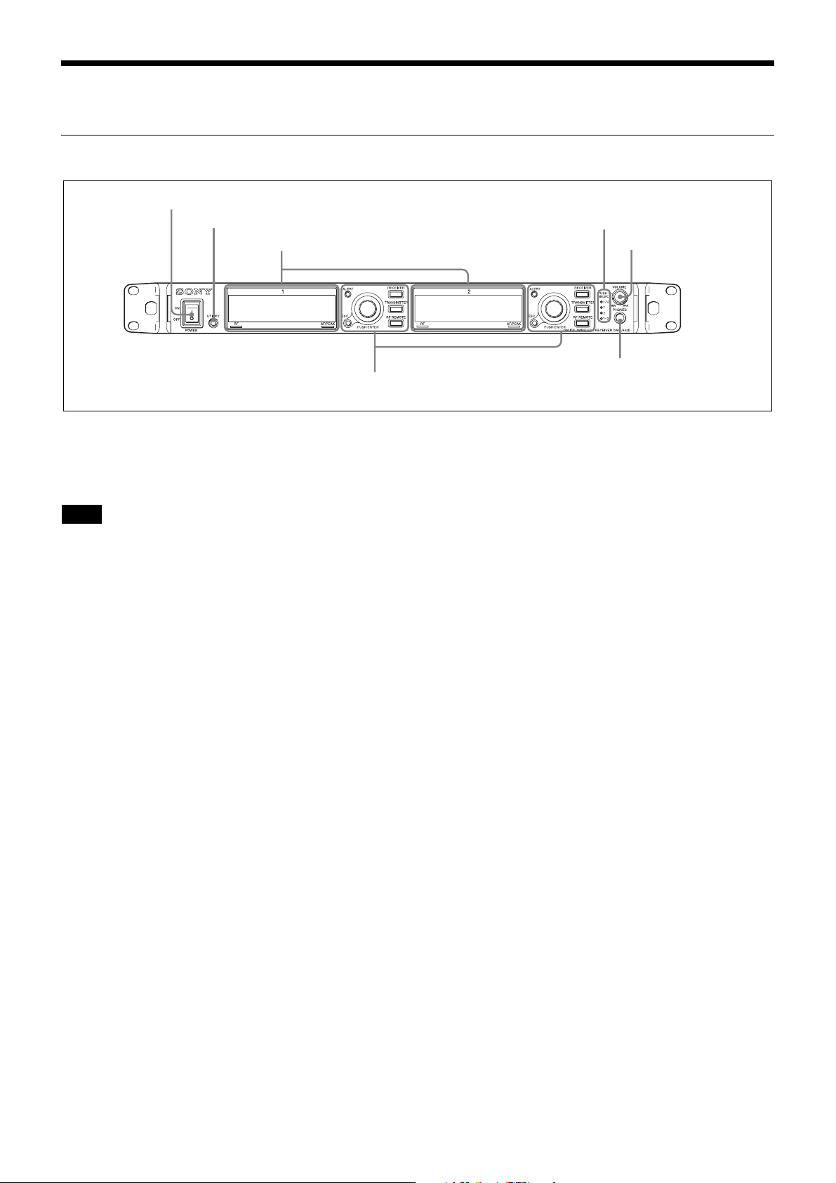
Front Panel
1 POWER switch
2 UTILITY button
1 Display (see page 7)
2 Controls (see page 8)
a POWER switch
Turns the receiver on or off.
Set to the \ position to turn the receiver on. Set to the a
position when turning off the main power supply.
Note
When DC power is being input, you cannot turn off the
power supply using this switch. To turn off the power
supply in such cases, turn off the connected external power
supply, or disconnect the connected cable.
3 Monitor indicators
d VOLUME control
5 PHONES terminal
b UTILITY (UTILITY menu) button
Press to display UTILITY menu. This button lights up
brightly during UTILITY menu operation.
c Monitor indicators
One of four indicators lights up corresponding to the
VOLUME control operation.
1/2: Audio from channel 1 is output from the L channel of
the headphones and audio from channel 2 is output from
the R channel.
1: Audio from channel 1 is output from the L and R
channels of the headphones.
2: Audio from channel 2 is output from the L and R
channels of the headphones.
1+2: Audio from channel 1 and 2 are mixed to be output L
and R channels of the headphones.
d VOLUME (monitor channel selection/monitor
volume) control
Press to change the audio output from the headphones.
Rotate to control monitor volume.
e PHONES (headphones) terminal
Connect the headphones here.
6
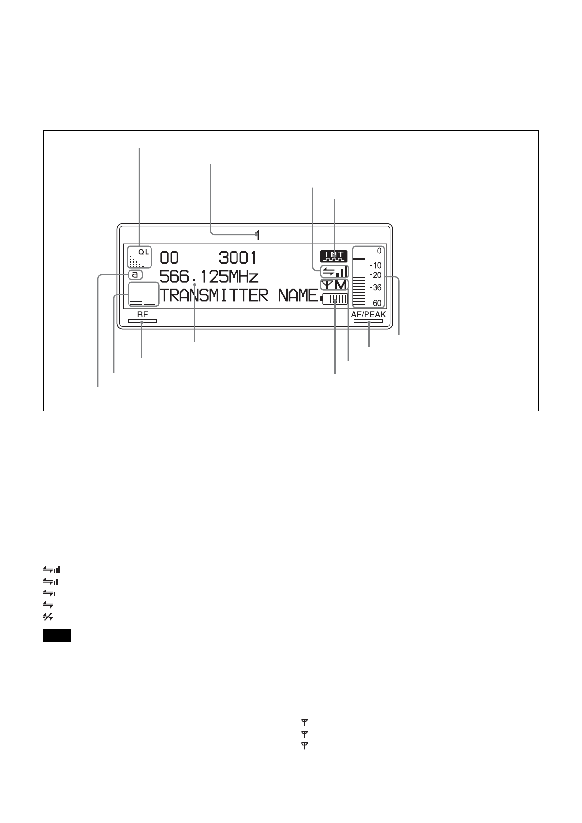
1 Display
The contents of the display before the DWR-R02DN enters menu operation (top display) are described below. Since the
top display shows information contained in the metadata sent from the transmitter as well as the receiver settings and
status, this can be used for operation monitoring.
The display contents of receiver channel 1 and 2 are the same. The display of receiver channel 1 is used for illustration
purposes.
1 QL meter
2 Receiver channel number
3 Cross Remote condition indication
4 Digital output sync indication
9 Reception channel information
0 RF indicator
qa RF level meters
qs Antenna selection indication
a QL (signal quality level) meter
Indicates the quality of data that is received.
This meter allows you to monitor RF signal deterioration
that may occur when there is signal interference or when
the transmitter is too far from the receiver.
b Receiver channel number
Indicates the receiver channel number.
c Cross Remote condition indication
Indicates the signal transmission condition of the wireless
remote control function (four levels).
: Good transmission
: Somewhat good transmission
: Somewhat poor transmission
: Poor transmission
: Unable to communicate with paired transmitter
Note
When the wireless remote control function (see page 27) is
off, this indication does not appear.
d Digital output sync indication
Indicates sync status of the signal output from the
DIGITAL OUT connectors.
INT: Output signal is in sync with the internal clock.
EXT: Output signal is in sync with the signal input from
the WORD SYNC IN connector.
5 Audio level meter
6 AF/PEAK indicator
7 Transmission power indication
8 Battery indication
e Audio level meter
Indicates the level of audio signal input to the transmitter.
The segments indicating below the reference input level of
the transmitter appear dimly.
When “MIC” is set for the reference input level on the
transmitter: Segments indicating –36 dBFs or below
appear dimly.
When “LINE” is set for the reference input level on the
transmitter: Segments indicating –20 dBFs or below
appear dimly.
For details on disabling the peak display, see “AF Peak
Level Hold Duration Setting (AF PEAK HOLD)” on
page 29.
f AF/PEAK (audio signal peak) indicator
Lights up green when the audio signal exceeding reference
level is input to the transmitter.
Lights up red when the audio signal exceeding –3 dBFs is
input to the A/D converter on the transmitter.
g Transmission power indication
Indicates the current transmission power setting. This
setting can be changed in the TRANSMITTER menu (see
page 26).
H: transmitting at 50 mW
M: transmitting at 10 mW
L: transmitting at 1 mW
7
For details on changing the transmitter settings, see
“Changing the Settings on the Transmitter” on page 31.
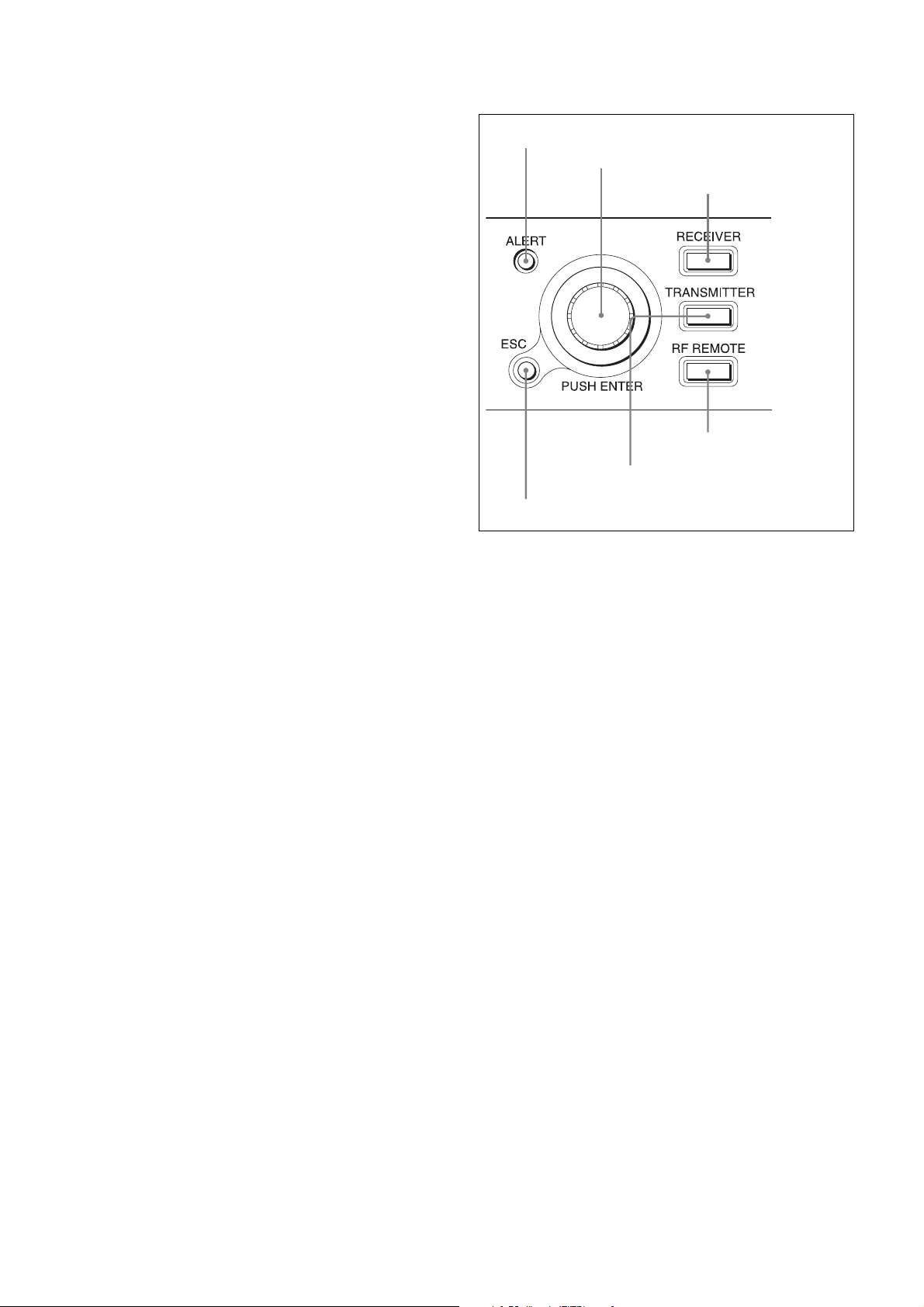
2 Controls
The control areas for channel 1 and channel 2 are identical.
h Battery indication
Based on metadata from the transmitter, this shows the
transmitter’s battery condition according to eight level
indications.
Replace both batteries when the battery indication starts to
flash.
For details on how to change the batteries on the
transmitter, refer to the Operating Instructions supplied
with the transmitter.
i Reception channel information
Shows the information on receiving signal and the
transmitter name.
First row: Group and channel
Middle row: Frequency of the channel
Last row: Transmitter name and sleep state
j RF (radio reception) indicator
Lights up to indicate the level of the signal input from the
ANTENNA a/b IN connector as follows.
On in orange: 80 dBµ or more
On in green: 25 dBµ to 80 dBµ
On in red: 15 dBµ to 25 dBµ
Off: Less than 15 dBµ
1 ALERT indicator
2 Jog dial
3 RECEIVER menu
4 RF REMOTE menu
5 TRANSMITTER menu button
6 ESC button
a ALERT (alert) indicator
Lights up red when error is detected.
button
button
k RF (radio reception) level meters
Indicates the level of the signal input from the ANTENNA
a/b IN connector. The number of segments that light up
depends on the input level.
l Antenna selection indication
Indicates the antenna currently selected by the diversity
function.
For the specific causes of alerts and remedies, see “When
the Alert Indicator Lights” on page 34.
b Jog dial
Rotate to select an item or a parameter value in the menu.
Press to enter the selected item or parameter value.
c RECEIVER (RECEIVER menu) button
Press to enter the RECEIVER menu. While in the
RECEIVER menu, this button lights up brightly.
d RF REMOTE (RF REMOTE menu) button
Press to enter the RF REMOTE menu. While in the RF
REMOTE menu, this button lights up brightly.
e TRANSMITTER (TRANSMITTER menu) button
Press to enter the TRANSMITTER menu. While in the
TRANSMITTER menu, this button lights up brightly.
f ESC (escape) button
Press to go back to the previous menu display.
8
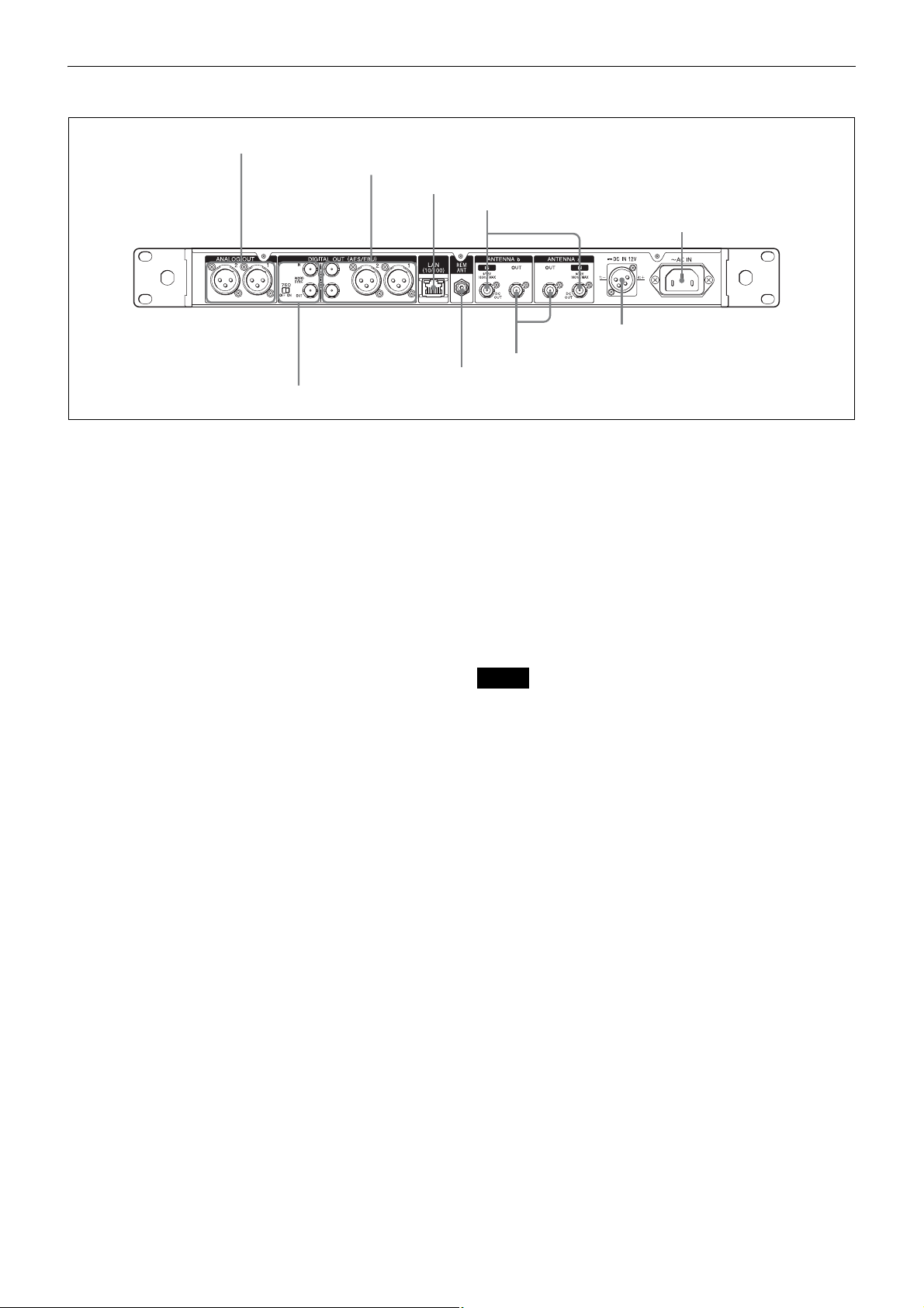
Rear Panel
1 ANALOG OUT 1/2 connectors
2 DIGITAL OUT 1/2 connectors
3 LAN (10/100) connector
4 ANTENNA a/b IN connectors
5 AC IN connector
3
4
6 DC IN connector
9 WORD SYNC IN/OUT connectors and 75 Ω termination switch
a ANALOG OUT (analog output) 1/2 connectors
(XLR type)
Connect the analog input connector of mixer, amplifier, or
other equipment.
You can use menu operations to set the output level and to
disconnect the XLR connector grounding (pin 1) and the
chassis grounding.
For details, see “Setting Analog Audio Output Level (BAL
OUT LEVEL)” on page 25 and “Ground Lift Function
(GROUND LIFT)” on page 25.
b DIGITAL OUT (digital output) 1/2/3/4 connectors
(1/2: XLR type, 3/4: BNC-R)
These connectors output a digital audio signal in AES3
format. Connect the digital input connector of mixer,
amplifier, or other equipment.
c LAN (Ethernet) (10/100) connector (RJ-45)
This is a 100Base-TX connector for network connection.
Connect to a Windows PC, in order to use the supplied
Wireless Studio software for communications with the
computer.
For connection to a computer, use a category 5 or superior
LAN cable with a maximum length of 100 m (approx.
330 ft). If the connection requires a total cable length
exceeding 100 m (approx. 330 ft), use a hub between the
computer and the DWR-R02DN.
Use the following type of cable when:
Directly connecting the computer and the
DWR-R02DN: Cross cable
Using a hub between the computer and the
DWR-R02DN: Straight cable
d ANTENNA a/b IN (antenna a/b input) connectors
(BNC-R)
Connect an optional UHF antenna (e.g., AN-820A) and the
supplied whip antenna to these connectors.
When an antenna is connected, this connector supplies 9 V
or 12 V DC power to the booster incorporated in the
antenna. When using an antenna which does not require a
8 REM ANT
7 ANTENNA a/b OUT connectors
power supply, you can turn off the power output by menu
operation.
For details, see “DC power supply setting for antennas
(ANT DC OUT)” on page 28.
Antenna attenuator can be also set with menu operation
according connection methods of the antennas.
For details, see “Antenna attenuator setting (ANT ATT a/
b)” on page 28.
Notes
• Do not short-circuit this connector.
• When connecting DWR-R02DN units in cascade, set
ANT ATT a/b to “0dB” and ANT DC OUT to “OFF” on
any DWR-R02DN unit that is not directly connected to
the antenna.
About the antenna gain and the cable loss
When the antenna with the booster is connected to the
DWR-R02DN and the antenna gain exceeds the coaxial
cable loss between the antenna and the DWR-R02DN, the
RF signal which exceeds the allowable level may be input
to this unit.
To prevent this, set the cable loss and antenna attenuator
(0dB, 5dB or 10dB) (see page 28) to meet the following
equation.
The RF indicator on the receiver lights in orange when the
input becomes 80 dBµ or higher, so you can use it as a
rough guide.
Gain of antenna booster - Cable loss between antenna
and this unit - Antenna attenuator setting (dB) = 0 dB
or less
9
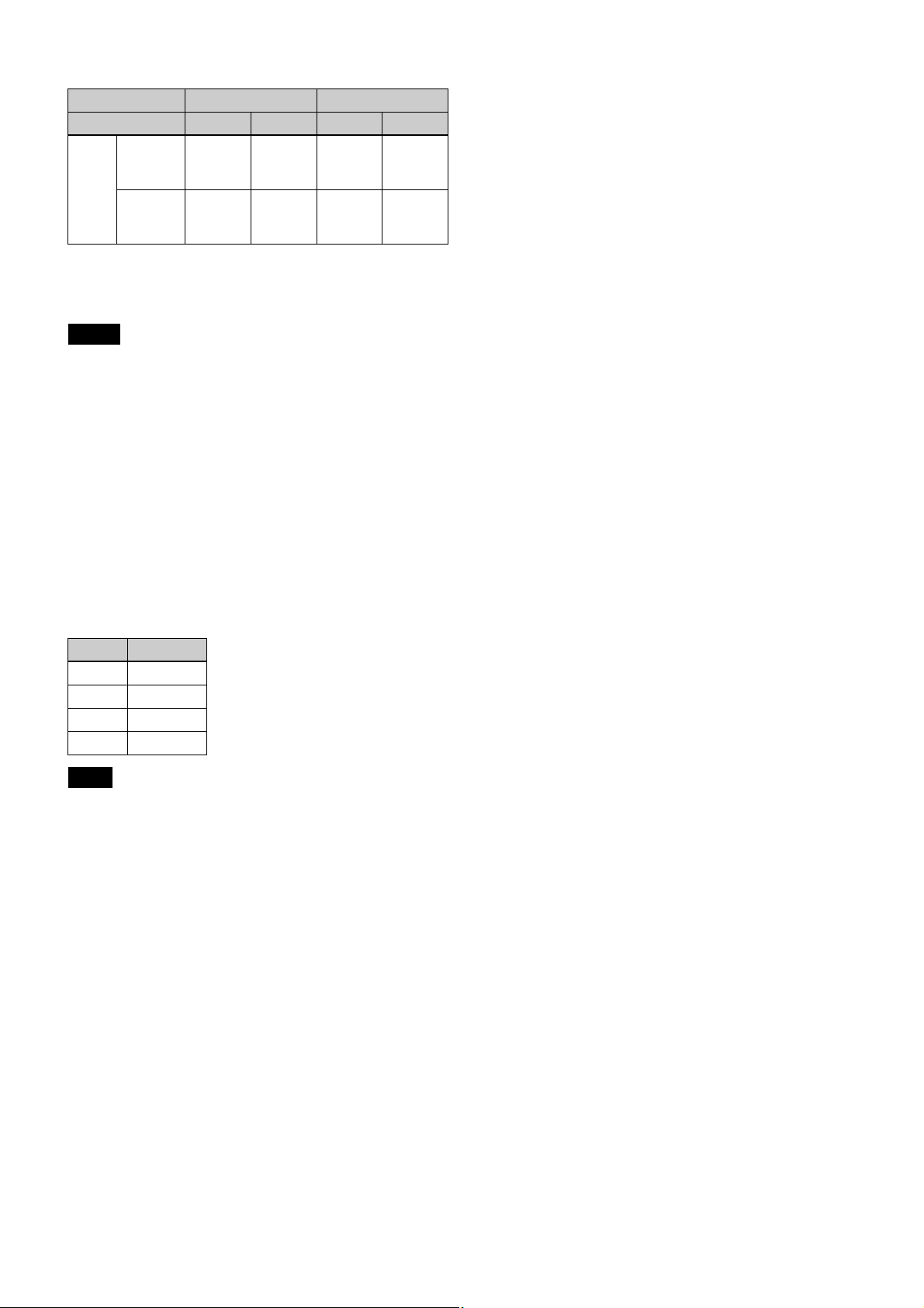
Reference: signal loss examples
Type of cable RG-212/U RG-213/U
Frequency 600 MHz 800 MHz 600 MHz 800 MHz
Cable
length
50 m
(approx.
165 ft)
100 m
(approx.
330 ft)
12 dB 14 dB 9 dB 11 dB
24 dB 28 dB 18 dB 22 dB
For details on gain of antenna booster, refer to the
operating instructions supplied with the antenna.
Notes
• The cable loss may differ depending on the manufacturer
of the cables.
• The rated resistance of ANTENNA a/b IN connectors is
50 Ω. If the cable with 75 Ω resistance is used, actual
signal loss is usually a few dB lower than the values on
the table above.
e AC IN connector
Connect to an AC power source with the supplied AC
power cord.
The sync signal input from the IN connector is output from
the OUT connector.
Set the 75 Ω termination switch of only the DWR-R02DN
unit at the end of the cascade connection to ON.
For details on connecting to the WORD SYNC connectors,
see “Connection Example of Word Clock and Audio” on
page 16.
f DC IN connector (XLR)
This connector connects to an external +12 V DC power
supply.
The DC IN pin configuration of the unit is as follows.
Pin No. Function
1–
2NC
3NC
4+
Note
Make connections using proper polarity. Incorrect polarity
may damage the unit.
Always check the polarity before making the connection.
AC power supply is prioritized when operating the unit.
To stop DC power supply, turn off the connected external
power supply or disconnect the connected cable.
g ANTENNA a/b OUT (antenna a/b output)
connectors (BNC-R)
These connectors output the signals input from the
ANTENNA a/b IN connectors. Using these connectors,
you can connect up to eight of DWR-R02DN units in
cascade.
h REM ANT (ST remote system antenna)
This is an external antenna for the ST remote system.
i WORD SYNC IN/OUT (sync signal input/output)
connectors and 75 Ω termination switch
When you want to synchronize digital output with an
external sync signal, input the external sync signal to the
WORD SYNC IN connector.
10
Preparation
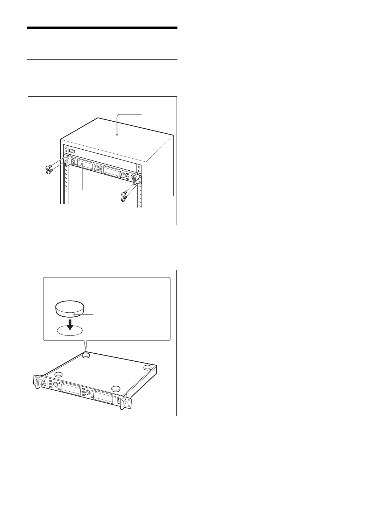
Rack Mounting
Use the EIA standard 19-inch rack (1U size) with a depth
of 350 mm to install the DWR-R02DN.
Rack
Screws
(+B M5 × 12)
DWR-R02DN
Screws
(+B M5 × 12)
To use the DWR-R02DN without installing
in the rack
Attach the supplied four feet to the bottom of this unit, as
illustrated below.
Attach the adhesive side of the feet to the circular
marks at the bottom of the unit.
Foot
To install the DWR-R02DN in the rack, be sure to remove
the attached feet.
11
System Configuration Examples
You can build a multi-channel system, ST remote system
(see page 4), or NT remote system (see page 4) shown
below in accordance with the scale and purpose of the
system you want to build.
You can improve user-friendliness by combining a multichannel system with a remote system.
The type and maximum number of equipment that can be
included in each system are described below.
Note
When any RMU-01 unit is detected in the Ethernet
connection, the system automatically operates in NT
remote system mode. When no RMU-01 unit is detected,
ST remote system mode is applied.
The wireless remote control function receives a change
command from the receiver or RMU-01 via a 2.4 GHz
signal, and replies with the metadata in the audio packet.
Therefore, use the wireless remote control function where it
will be within range of the audio signal from the transmitter.
Multi-channel
system
DWR-R02DN 1 to 41 1 to 3 1 to 41
Sony digital
wireless
transmitter
RMU-01 Not required Not required 1 to 9
Wireless
Studio
1 to 82 1 to 6 1 to 82
Can be used to monitor the status of
receivers, transmitters, and RMUs
ST remote
system
NT remote
system
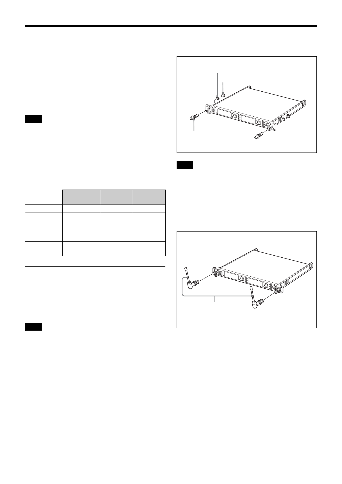
Antenna mount with
BNC connector
Note
You can also attach the antennas so that the hexagon nuts
are located on the front side of the front panel.
If you have trouble securing the hexagon nuts on the back
side of the front panel, insert the antenna mounts with
BNC connectors into the front panel from the back side,
and secure the nuts on the front side.
2
Attach the supplied whip antennas.
Tooth lock washer
Hexagon nut
Using the Supplied Antennas
To maximize the reception performance of this unit, we
recommend using optional AN-820A or AN-01 UHF
antennas.
For narrow service areas, however, you can also use the
supplied whip antennas.
Note
When using the supplied whip antennas, be sure to verify
your service area beforehand.
The supplied whip antennas can be attached to the front or
rear panel of the unit.
Front panel attachment
1
Insert commercially available antenna mounts with
BNC connectors into the front panel, and secure them
with hexagon nuts (14 mm).
Whip antenna
(supplied)
12
3
Use commercially available BNC cables (50 Ω, 60 cm
or longer) to connect the antenna mounts with BNC
connectors to the ANTENNA a/b IN connectors on the
rear panel of the unit.
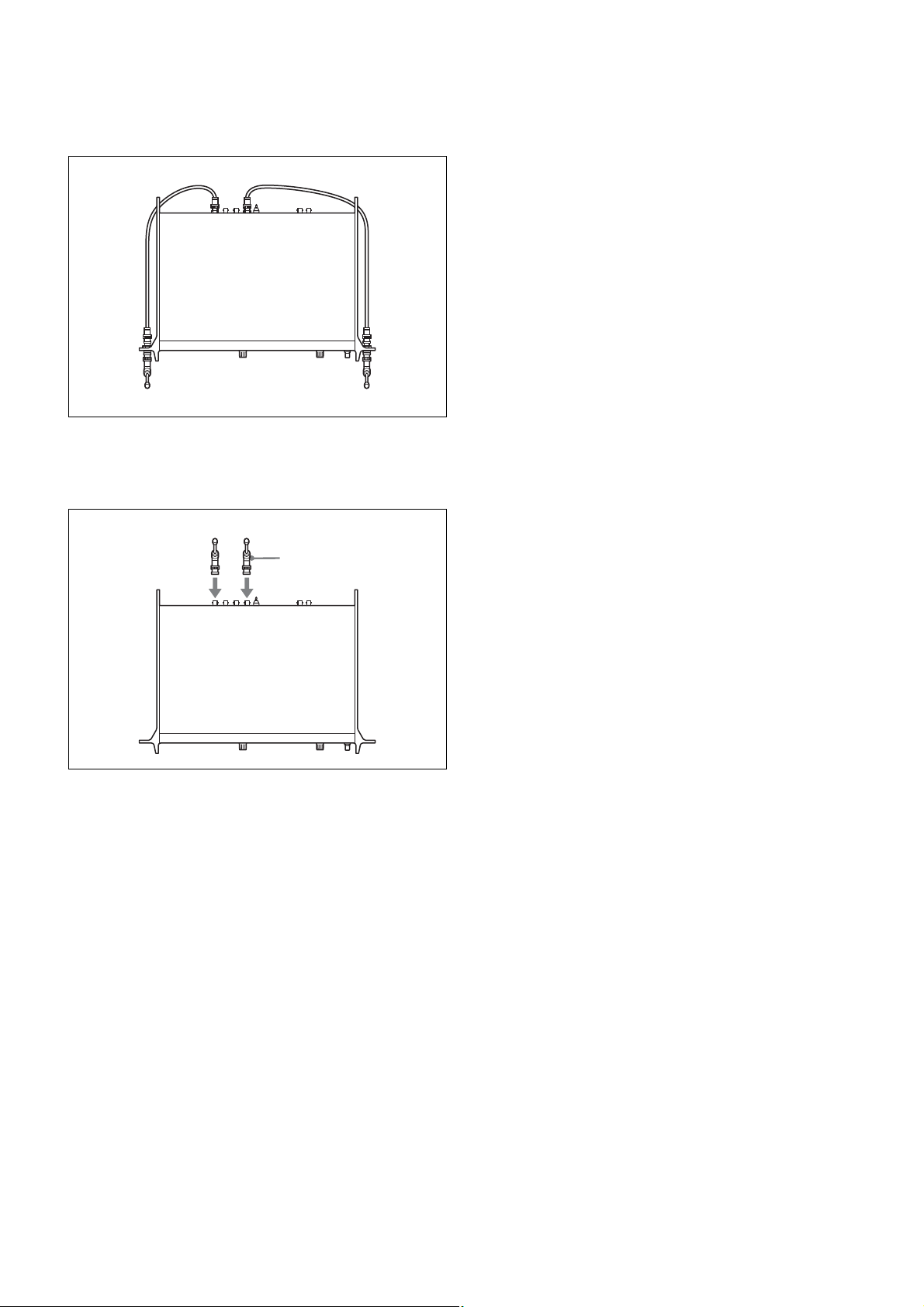
Rear panel attachment
Attach the supplied whip antennas to the ANTENNA a/b
IN connectors on the rear panel.
Whip antenna
(supplied)
13
 Loading...