

Sony DWR-R02D,DWR-R01D User Manual

4-177-128-13 (2)
Wireless Studio
User’s Guide Version 3.0x
Before using this software, please read this manual thoroughly
and retain it for future reference.
DWR-R01D/R02D
© 2010 Sony Corporation

NOTICE TO USERS
© 2010, 2011, 2012 Sony Corporation. All rights reserved.
This manual or the software described herein, in whole or
in part, may not be reproduced, translated or reduced to
any machine readable form without prior written approval
from Sony Corporation.
SONY CORPORATION PROVIDES NO WARRANTY
WITH REGARD TO THIS MANUAL, THE
SOFTWARE OR OTHER INFORMATION
CONTAINED HEREIN AND HEREBY EXPRESSLY
DISCLAIMS ANY IMPLIED WARRANTIES OF
MERCHANTABILITY OR FITNESS FOR ANY
PARTICULAR PURPOSE WITH REGARD TO THIS
MANUAL, THE SOFTWARE OR SUCH OTHER
INFORMATION. IN NO EVENT SHALL SONY
CORPORATION BE LIABLE FOR ANY
INCIDENTAL, CONSEQUENTIAL OR SPECIAL
DAMAGES, WHETHER BASED ON TORT,
CONTRACT, OR OTHERWISE, ARISING OUT OF OR
IN CONNECTION WITH THIS MANUAL, THE
SOFTWARE OR OTHER INFORMATION
CONTAINED HEREIN OR THE USE THEREOF.
Sony Corporation reserves the right to make any
modification to this manual or the information contained
herein at any time without notice.
The software described herein may also be governed by
the terms of a separate user license agreement.
2

Table of Contents
Using This User’s Guide.............................4
Notations Used in This User’s Guide ........... 4
About the Window Displays in This User’s
Guide ................................................... 4
Features .......................................................4
Preparing the Software and Devices.........5
Installing the Software.................................. 5
Setting Up the Network ................................ 6
Connecting to the Network........................... 7
Parts Identification......................................8
Menus ...........................................................9
Basic Operations.......................................11
Device Detection and Monitoring .............. 11
If Problems Occur during Monitoring ........ 12
Selecting Channel Plans ............................. 13
Pairing Receiver Channels and
Transmitters....................................... 14
Controlling Devices.................................... 15
Recording the Signal Environment during
Operation........................................... 17
Using Settings Files .................................... 17
Device List Window...................................19
Main Window .............................................21
Status Viewer and Meter Icons................... 21
Sub Window...............................................23
Message Log Tab........................................ 23
Property List Tab ........................................ 24
RF Chart Grapher Tab ................................ 25
RF Chart Analyzer Tab............................... 27
Setup Windows..........................................28
Property Window........................................ 28
Channel Plan Adviser Window .................. 30
Omit IP address list Window...................... 34
Setting lock Window .................................. 35
Receiver CH Label setting Window ........... 35
AF peak hold setting Window .................... 36
Startup setting Window .............................. 36
Region setting Window .............................. 37
Table of Contents
3

Using This User’s Guide
Features
This User’s Guide explains the use of the Wireless Studio
software supplied with the DWR-R01D/DWR-R02D
Digital Wireless Receiver.
To make the most of this guide, please use it in conjunction
with the Operating Instructions supplied with the DWRR01D and DWR-R02D.
Notations Used in This User’s Guide
• Clicking a menu or button and then selecting a sub-menu
is expressed as follows: Select “Menu (or button) > (submenu name)”.
Example: Select “File menu > Open”.
• Holding down one key on the keyboard while pressing
another is indicated by a “+” sign between the two keys.
Example: Press Ctrl + P.
About the Window Displays in This User’s Guide
The window displays that appear in this guide may differ
from those on your PC, due to differences in the operating
system being used.
The Wireless Studio software supplied with the
DWR-R01D/DWR-R02D Digital Wireless Receiver
(herein referred to as the “receivers”) allows you monitor
and control a digital wireless system via a network.
The digital wireless system can be accessed from up to six
computers.
Wireless Studio has the following features.
Device monitoring
The software includes a status viewer for monitoring the
operation statuses of the receivers, RMU-01 Remote
Control Units, and transmitters.
The status viewer allows you to monitor a list of
information that is identical to the information that appears
on the initial display of the receiver.
Channel plan selection function
Select a channel plan that is suitable for your signal
environment to ensure stable operations.
Channel Plan Adviser allows you to select a channel plan
while taking into account factors such as other TV
broadcast waves (that you researched beforehand),
frequencies used by other wireless devices in the area, and
frequencies detected via the channel scan.
Error logging function
The software automatically saves log files of problems that
occur during operation. You can review the error histories
at a later time by using a text editor to view the stored log
files.
Device control function
The software allows you to control the receivers and the
transmitters that are paired with the receivers. Control
operations are performed from the Property window and
the Property List tab.
The Property window allows you to control a single
receiver and its paired transmitter while viewing their
operation statuses.
The Property List tab allows you to display the settings of
multiple receivers and transmitters in a list, and perform
fast control operations such as applying the same settings
to all the devices simultaneously.
Recalling stored settings and monitoring
information
Information such as the setting values of devices and the
arrangement of devices in the status viewer can be saved
as a file.
You can recall such information in Wireless Studio at a
later time by loading these stored files.
The setting values recalled in Wireless Studio can be
applied to all the devices.
4
Using This User’s Guide / Features

Pairing-assist function
The software includes a pairing wizard to assist in pairing,
an operation that is necessary to enable remote control of
transmitters via wireless remote control.
Save and analyze functions for signal
environment timelines
The RF Chart Grapher function allows you to monitor and
save the signal environment and alert information on a
timeline, and the RF Chart Analyzer function allows you
to reference the files saved with the RF Chart Grapher.
Preparing the Software and Devices
Installing the Software
Notes
• If the older version of Wireless Studio is already
installed in the PC, uninstall it (see page 6).
• Quit all applications before installing the software.
• Be sure to log in as the administrator.
Notes on installation
The installation procedure below describes the operation
on the PC that runs Windows XP. Note that the procedure
may vary according to the operating system.
1
Insert the CD-ROM “Wireless Studio” in your CDROM drive.
2
Click “Start” and then click “Run”.
3
Click “Browse” and then select the CD-ROM drive.
4
Select “setup.exe” and click “Open”.
This opens the “Welcome to the InstallShield Wizard
for Wireless Studio”.
5
Click “Next”.
A message “Choose an area” appears.
If Wireless Studio is already installed, a message
“Program Already Installed” appears. When this
message appears, select “Repair” to overwrite the
installation, or select “Remove” to first uninstall the
software, and then perform step 4 again.
6
Select your region and click “Next”.
7
Verify and if necessary, change the location where the
software is installed.
To change the location, click “Change...” and change
the location where the software is installed.
8
Click “Next”.
9
Click “Install”.
Installation starts.
When all application files have been copied to the PC,
a message “InstallShield Wizard Completed” appears.
10
Click “Finish”.
Preparing the Software and Devices
5
To uninstall the software
Note
The uninstallation procedure below describes the
operation on the PC that runs Windows XP. Note that the
procedure may vary according to the operating system.
Click and select “Add or Remove Programs” in the
Windows Control Panel, then select “Wireless Studio”
from the list, and then delete it.
Setting Up the Network
This section describes the network settings for the
receiver, RMU-01, and PC.
IP addresses and subnet masks
• If you are not using a standard network line connection,
configure the following private address. Configure
values that are unique within the network for the “*”
value.
IP Address: 192.168.0.*
Subnet Mask: 255.255.255.0 (fixed length)
• If you are using a standard line connection, consult your
network administrator.
Receiver Network Settings
Make settings on the front panel of the receiver.
For details on making the settings, refer to the Operating
Instructions supplied with the receiver.
RMU-01 Network Settings
Make settings by using the Setting Tool software supplied
with the RMU-01.
5
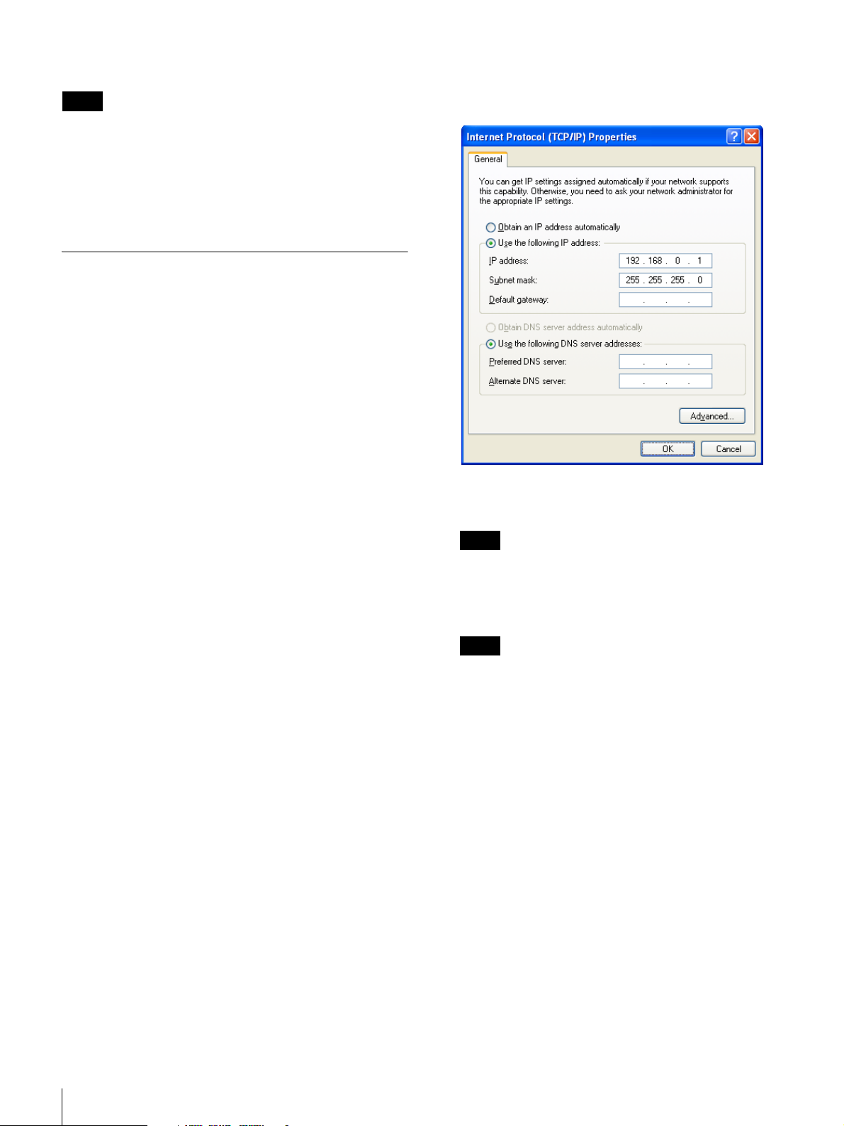
Double-click “Internet Protocol (TCP/IP)”.
The internet protocol (TCP/IP) properties window
opens up.
6
Click “Use the following IP address”, and then enter
the IP address in the IP address field.
Note
Make sure not to use an IP address that is already
assigned to another device on the network.
7
Enter the subnet mask into the Subnet mask field.
Note
If you configure a value other than “255 255 255 0”,
the search for the receiver on the network will take a
long time.
For details on making the settings, refer to the User’s
Guide supplied with the RMU-01 Setting Tool.
PC Network Settings
1
Select “Start > Control Panel > Network and Internet
Connections”.
2
Click “Network Connections”.
3
Right-click the local area connection icon and then
click “Properties”.
4
Double-click “Internet Protocol 4 (TCP/IP)”.
The properties window of the local area connection
opens up.
6
Preparing the Software and Devices
8
Click “OK” to close the internet protocol (TCP/IP)
properties window.
9
Click “Close” to close the local area connection
properties window.
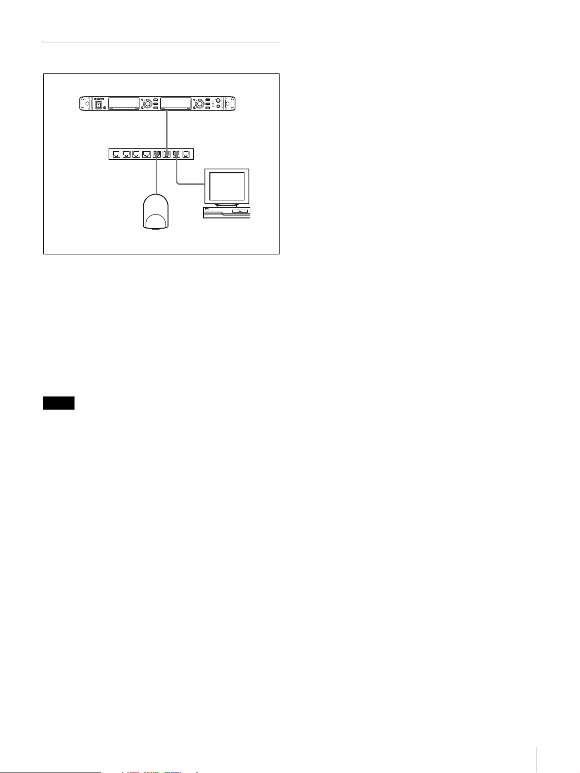
Connecting to the Network
Receiver
Hub
PC
RMU-01
By using the straight LAN cables, connect the receiver,
RMU-01, and the PC through the hub. When the network
connection is correctly made, the LED on the LAN
connector area at the rear of the receiver lights up green.
Connect the devices required for system operation to the
rear panel of the receiver.
For details on connecting devices, refer to the Operating
Instructnions supplied with the receiver.
Notes
• If the LED on the LAN connector area at the rear of the
receiver does not light up green, check the connection.
• For connections, use a category 5 or superior LAN cable
with a maximum length of 100 m (330 ft). If the
connection requires a total cable length exceeding 100 m
(330 ft), use a hub between the PC and the device.
• Use the cross cables when directly connecting the PC
and the devices.
• Do not touch the LAN connector directly with your
hands. The transfer of static electricity may result in
malfunction of the unit. As static electricity can
discharge from your body and clothes, be sure to remove
any static electricity before connecting or disconnecting
the LAN cable.
Preparing the Software and Devices
7
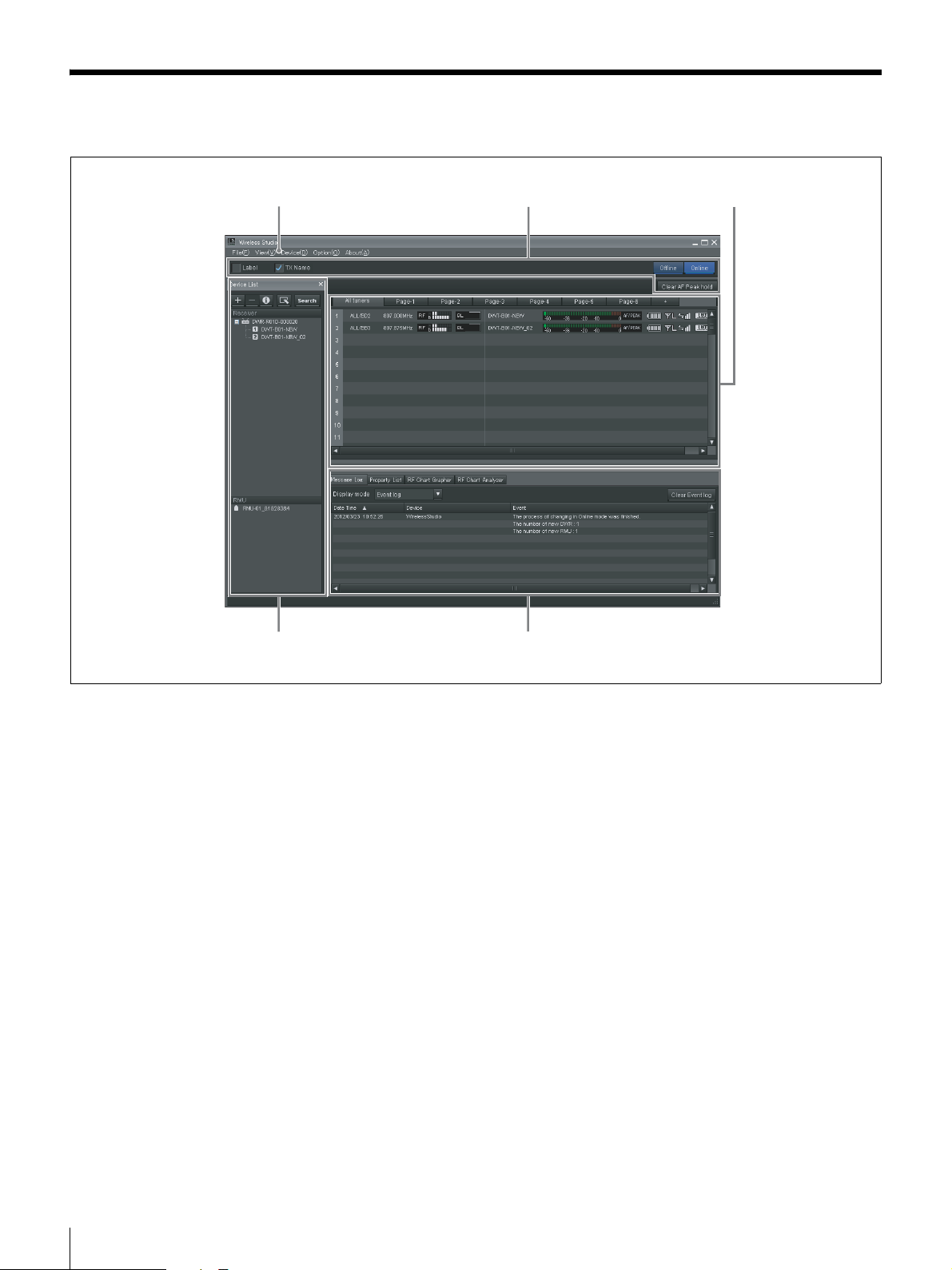
Parts Identification
45
123
a Menu
Click on a menu to display the commands in that menu.
For details, see “Menus” on page 9.
b Toolbar
The following settings are available on the toolbar.
Label: Shows or hides labels.
TX Name: Shows or hides transmitter names.
For details, see “Selecting whether to display labels and
transmitter names” on page 36.
Offline / Online: Switches between online mode and
offline mode.
Clear AF Peak hold: Releases the hold status of the AF
level meters that appear in the status viewer.
For details, see “AF peak hold setting Window” on
page 36.
c Main window
Information obtained from the receivers is displayed in the
status viewer of the main window. This allows you to
monitor signal reception, audio levels, and other status
information for the receivers.
For details, see “Main Window” on page 21.
d Device List window
Lists the receivers and RMU-01 units that exist on the
network.
The devices in the list can be registered to the status viewer
for monitoring, or controlled by opening their Property
windows.
For details, see “Device List Window” on page 19.
e Sub window
Consists of the following tabs:
Message Log tab
Displays warnings and error messages that occurred for
devices. The warnings and error messages that appear here
are automatically saved as log files.
For details, see “Message Log Tab” on page 23.
8
Parts Identification

Property List tab
Displays a list of setting values for multiple receivers and
transmitters. The devices displayed here are those that are
registered to the pages displayed in the status viewer. You
can control the receivers and transmitters by selecting the
cells in the list and modifying the settings.
For details, see “Property List Tab” on page 24.
RF Chart Grapher tab
Records the signal reception status obtained from the
receivers and up to 24 hours worth of warnings related to
the reception status.
Menus
File menu
This menu allows you to load existing setting files and
save settings.
The File menu has the following commands.
Note
The New, Open, and Save commands can only be used in
offline mode.
For details, see “RF Chart Grapher Tab” on page 25.
RF Chart Analyzer tab
Allows you to view the information saved in the RF Chart
Grapher tab.
For details, see “RF Chart Analyzer Tab” on page 27.
New: Creates a new settings file.
Open: Opens a setting file.
Save: Saves the current settings to a setting file that is
already open by overwriting the contents of the file. For
setting files that are still unnamed, this command can be
used in the same way as the “Save as” command to add a
name to a setting file before saving it.
Save as: Adds a name to the current settings and saves
them to a setting file (file extension: dwl2).
Exit: Exits the Wireless Studio software.
View menu
This menu allows you to show or hide each window, and
restore the size and layout of each window to their default
state from immediately after installation.
The View menu has the following commands:
Default Size and Layout: Restores the size and layout of
windows to their default state from immediately after
installation.
Device List: Shows or hides the device list.
Status Viewer: Shows or hides the status viewer.
Message Log: Shows or hides the Message Log tab of the
sub window.
Property List: Shows or hides the Property List tab of the
sub window.
RF Chart Grapher: Shows or hides the RF Chart Grapher
tab of the sub window.
RF Chart Analyzer: Shows or hides the RF Chart
Analyzer tab of the sub window.
Device menu
This menu allows you to make network connection
settings for each device.
The Device menu has the following commands:
Online monitoring and control: Switches between
online mode and offline mode. The system is in online
mode when the check mark appears next to the command,
and offline mode when the check mark is cleared.
Load settings: Applies the setting values configured in
Wireless Studio to the receivers and transmitters (available
in offline mode only).
For details, see “Using Settings Files” on page 17.
Menus
9

Add a new device: Opens the “Add a new device”
window. Use this when entering IP addresses to add
devices to the device window manually.
For details, see “Manually adding a receiver/RMU-01 to
the device list window” on page 20.
Region setting: Opens the “Region setting” window. Use
this when you want to use a receiver model from a region
other than the region selected during Wireless Studio
installation.
For details, see “Region setting Window” on page 37.
Search devices: Automatically detects the receivers and
RMU-01 units on the same subnet (available in online
mode only).
Omit IP address list: Opens the Omit IP address list
window (available in offline mode only).
For details, see “Omit IP address list Window” on
page 34.
Setting lock: Opens the “Setting lock” window. Use this
to disable or enable the modification of receiver and
transmitter settings from Wireless Studio.
For details, see “Setting lock Window” on page 35.
Pairing wizard: Opens the “Pairing Wizard” dialog box.
Use this to pair receiver channels and transmitters.
For details, see “Pairing Receiver Channels and
Transmitters” on page 14.
Channel Plan Adviser: Opens the “Channel Plan
Adviser” window. Use this to select channel plans using
Channel Plan Adviser.
About menu
The About menu has the following commands:
Link to Message Log: Opens the folder in which log files
for warnings and error messages are stored. Messages that
appear in the Message Log tab of the sub window are
automatically saved as log files.
System version information: Opens the “System version
information” window. Displays the versions of the
receivers and RMU-01 units on the network, and the
transmitter versions received from the transmitters by the
receivers.
Version information: Indicates the version of the
Wireless Studio software.
For details, see “Selecting Channel Plans” on page 13
and “Channel Plan Adviser Window” on page 30.
Option menu
The Option menu has the following commands:
Receiver CH Label setting: Opens the “Receiver CH
Label setting” window. Use this to configure labels for
each receiver channel.
For details, see “Receiver CH Label setting Window” on
page 35.
AF peak hold setting: Opens the “AF peak hold setting”
window. Use this to configure the hold settings for the
peak levels of the AF/PEAK level meters.
For details, see “AF peak hold setting Window” on
page 36.
Startup setting: Opens the “Startup setting” window. Use
this to configure startup operations for Wireless Studio.
For details, see “Startup setting Window” on page 36.
10
Menus
Basic Operations
Wireless Studio operates in one of two modes, online
mode and offline mode.
Online mode
Online mode is used to enable real-time communication
between the receivers and RMU-01 units via the network,
and allow monitoring and control of the devices.
Device Detection and Monitoring (page 11)
Locate the receivers and RMU-01 units on the network, and
enable monitoring for these devices. This operation is
necessary for the pairing and device control operations that
follow.
r
Selecting Channel Plans (page 13)
Scan the signal environment using the channel scan
function of the receiver, and view the results while selecting
the channel plan.
r
Pairing Receiver Channels and Transmitters (page 14)
Pairing is necessary to enable control of the transmitters via
wireless remote control. Use the pairing wizard in Wireless
Studio to pair receivers and transmitters.
Device Detection and Monitoring
1
Select “Start > All Programs > Sony > Digital Wireless
Microphone System > Wireless Studio” to start up the
software.
2
Place a check mark next to “Online monitoring and
control” in the Device menu.
The system enters online mode, and the receivers and
RMU-01 units are automatically detected and added to
the device list window.
Receivers that are added to the device list are
automatically registered to the “All tuners” page of the
status viewer where they can then be monitored.
For more information on window contents, see “Status
Viewer and Meter Icons” on page 21.
Note
The Windows firewall or your security software’s
firewall may prevent devices from being detected
automatically. If the devices are not detected
automatically, disable the firewall settings.
r
Controlling Devices (page 15)
Perform device controls from the Property window and the
Property List tab of the sub window.
r
Recording the Signal Environment during Operation
(page 17)
Record the signal levels and changes in QL for each
receiver. Warnings related to signal reception and QL will
also be recorded.
Offline mode
Offline mode is used for settings file operations (saving,
recalling, etc.), and applying the settings displayed in
Wireless Studio to all devices simultaneously.
Using Settings Files (page 17)
Setting values for receivers and transmitters can be saved
as files. You can recall previously used setting values by
opening a stored settings file and applying it to the devices.
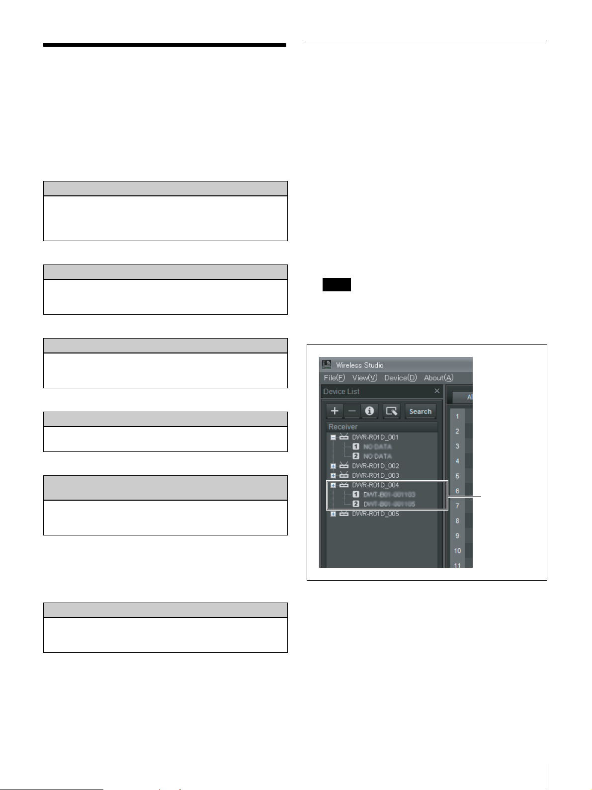
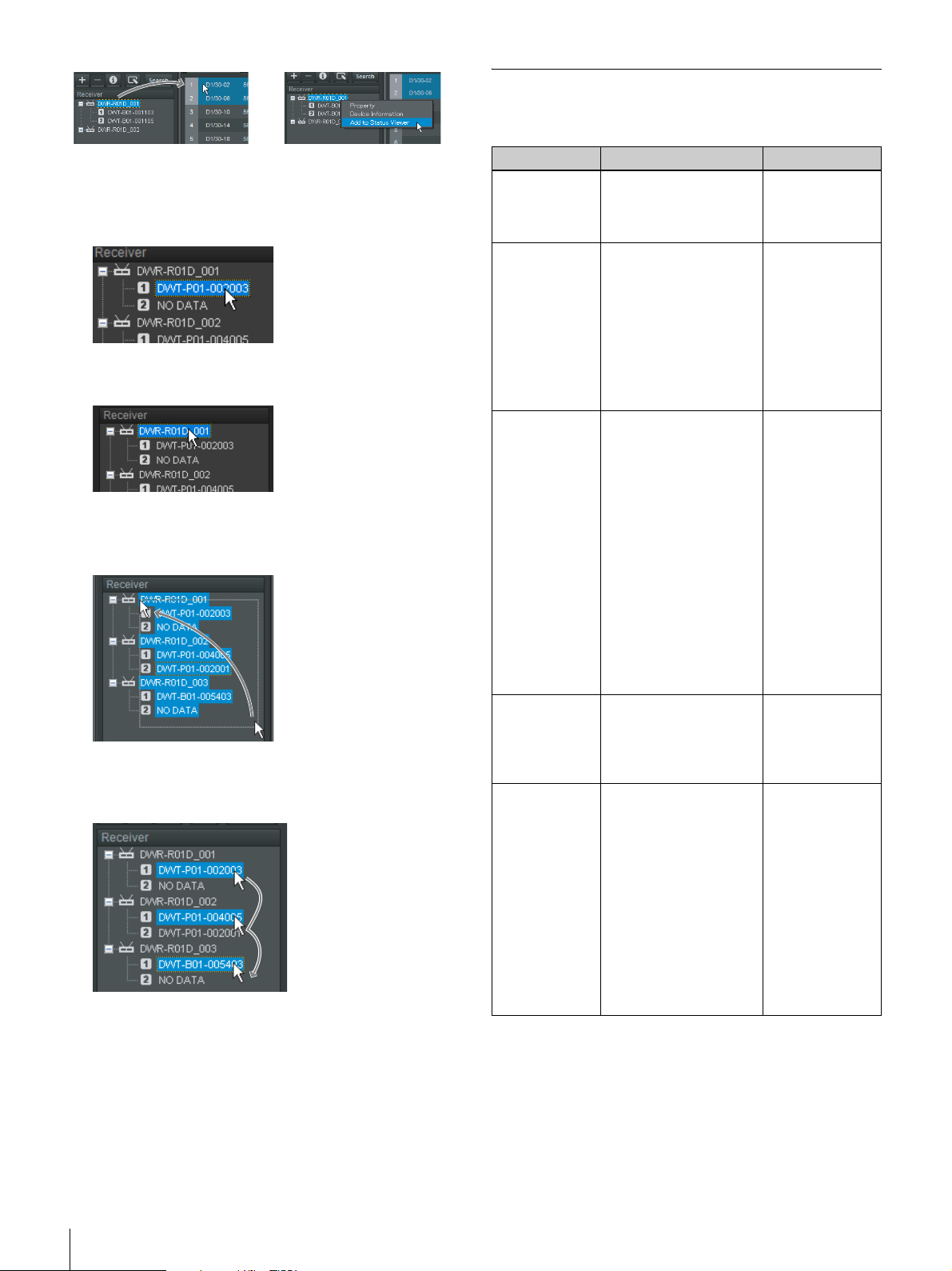
Click [+] to the
left of a receiver
icon to display
the receiver
channels.
To monitor a particular set of receiver channels
Display a page in the status viewer other than the “All
tuners” page, and register receiver channels manually to
monitor only the receiver channels that you select.
To display a receiver channel in the status viewer, drag the
receiver channel selected in the device list and drop it in
the status viewer, or right-click the receiver channel and
select “Add to Status Viewer” in the context menu that
appears.
Basic Operations
11
If Problems Occur during Monitoring
See the following table to remedy the problem.
The following methods are available for selecting receiver
channels.
• When you click a single receiver channel, that receiver
channel is selected.
• When you click a receiver, the two receiver channels that
are built into that receiver are selected.
• When you click and drag on the background area, all of
the receiver channels within the dragged area are
selected.
• When you click receiver channels while holding down
the Shift key or Ctrl key, all of the clicked receiver
channels are selected.
To set devices to be excluded from automatic detection
Use the Omit IP address list window (see page 34).
Problem Cause Remedy
The receiver is
not recognized.
It takes long
until the
receiver is
recognized.
In the dialog
box indicating
the receiver
detection
results, an
abnormal value
appears in the
IP address
field.
The receiver is
not detected
automatically.
The “Wireless
Studio
detected
version
unmatch with
DWR-R01D.
Please update
the firmware of
DWR-R01D to
ver.1.20 or
later” message
appears, and
monitoring is
disabled.
The host name or IP
address is already
assigned to another
device.
If the network has a PC
that is connected to a
broadband router or the
Internet, it may take
several minutes to
recognize the receiver.
If your PC is equipped
with or connected to a
modem or ISDN router,
the Wireless Studio
software may not
function properly when
you start it up when
either of the conditions
described below exist.
This is because the PC
will attempt to detect
device through the
modem or router.
• The receiver is turned
off.
• The LAN cable is
disconnected.
The Windows firewall or
your security software’s
firewall may prevent
devices from being
detected automatically.
Wireless Studio Ver. 3.0
or later supports Ver.
1.20 or later of the
DWR-R01D firmware.
Check the host
name or IP
address settings.
Construct a
separate
network apart
from the one
containing the
PC with the
broadband
router or the
Internet
connection.
Turn on the
receiver and
make sure the
LAN cable is
connected.
Disable the
firewall settings
on the computer.
Update the
firmware of the
receivers. For
details, contact
your Sony
dealer.
12
Basic Operations
 Loading...