

Sony DWM02/42, DWM02/30, DWRR02D/14, DWTB01/E1424, DWTB01/E3040 Product Information
...
Digital Wireless
Microphone System
System Integration Guide

Table of Contents
Outline 3
Digital Wireless Outline 4
What is DWX? ...........................................................4
What Is WiDIF-HP? ....................................................5
What Is Cross Remote? ...........................................6
Technology 7
WiDIF-HP Technology ...............................................7
Key Features of WiDIF-HP .......................................10
WiDIF-HP Precautions .............................................16
Cross Remote Technology ....................................20
Cross Remote Features .........................................26
Cross Remote Precautions ....................................30
Configuring a DWX System 31
DWX System Configuration ...................................31
System Sections and Configuration Flow .................31
System Limitations ......................................................32
Audio Equipment Selection ..................................33
Equipment Features ...................................................33
Network System Configuration ............................. 57
System Configuration .................................................57
Equipment Features ...................................................60
Installation of Remote Control Unit RMU-01 ..............61
Network Device Connections ....................................63
Making and Checking Network Settings .............64
2.4 GHz area operation check ..................................65
Step 1 Network Setup ................................................66
Step 2 Checking Equipment Connections ..............69
Step 3 Checking for 2.4 GHz Interference ................71
Step 4 Checking the Monitor Function ....................71
Step 5 Checking the Control Function ....................71
Sample System Configaration 74
Sample Minimum System Configuration
(2 channels) .............................................................74
Sample Small-Scale System Configuration Using
Remote Control Unit RMU-01 (7 – 16 channels) .....74
Sample Medium-Scale System Configuration Using
Antenna Divider WD-850 (17 channels or more) ...75
Sample Maximum System Configuration
(82 channels) ...........................................................76
References 77
List of Supported Frequencies ...................................77
Equipment Specifications ..........................................78
UHF System Configuration ....................................37
System Configuration .................................................37
Equipment Features ...................................................38
Antenna Installation Requirements ...........................40
Making and Checking RF Settings (UHF) .............44
Checking the RF Level (UHF) ......................................45
Step 1 Channel Plan Selection .................................46
Step 2 Antenna Installation and Setup ....................48
Step 3 Checking the Service Area With
One Channel ............................................................51
Step 4 Checking Third-order Intermodulation
Distortion ...................................................................52
Step 5 Checking Simultaneous Multi-channel
Operation .................................................................53
Troubleshooting ..........................................................55
Quick Check ...............................................................56
2

Outline
Sony started in the wireless microphone business in 1974 with the introduction of a 40-MHz band VHF system. This was
soon followed by an industry-first PLL Synthesized VHF system in 1983. Continually enhancing its wireless products line,
Sony introduced a groundbreaking 800-MHz band PLL Synthesized UHF Wireless Microphone system at the NAB event
in 1991. Throughout this period, Sony has been at the forefront of technology -- offering the first UHF PLL Synthesized
Wireless Microphone system with 282 selectable channels, introducing a space diversity RF reception system, realizing
42 operational channels with a 36-MHz band width, and more. These technologies have been adopted for the range
of Sony wireless microphone systems available today. Providing superb audio performance, operational flexibility,
and reliability, these systems have been widely accepted in a broad range of professional audio applications from
broadcasting, production, and theater to entertainment and conferences.
Sony has consistently developed these systems with the following in mind:
Superb audio performance with wide dynamic range
Highly stable signal transmission
Flexible simultaneous multi-channel operation
While Sony wireless microphone systems have greatly innovated professional audio operations, the growth in
popularity of high-definition (HD) content creation and digital audio recording/transmission has called for the
development of large-scale, multi-channel wireless microphone systems with improved sound quality. In response to
these important requirements, Sony continues to strive to develop a digital audio wireless transmission technology
that can match the quality and performance of a wired transmission technology and that can also cope with the
increasing need for simultaneous multi-channel operation.
Outline
Sony is offering a broad lineup of digital wireless products available as options for various audio systems. Solutions
range from electronic news gathering (ENG) systems with a bundled camcorder to full-fledged studio/concert systems
supporting simultaneous multi-channel operation. This provides users with the flexibility to configure exactly the digital
wireless microphone system they need.
3
DWX Transmitter Series
DWX Microphone Series
UHF Accessories (Option)
Status Monitor & Parameter Control
Network Accessories (Option)
Status Monitor & Parameter Control
DWX Receiver Series
DWX Adapter
DWM-01/F31
Digital Wireless
Microphone
DWR-R01D
Digital Wireless Receiver
DWM-01/C31
Digital Wireless
Microphone
DWT-B01
Digital Wireless
Transmit ter
DWT-P01
Digital Wireless
Transmit ter
AN-820
UHF Antenna
WD-850
UHF Antenna
Divider
AN-01
UHF Antenna
DWR-S01D
Digital Wireless Receiver
DWA-01D
Digital Wireless Adapter
BNC Cable
LAN Cable
RMU-01
Remote Control Unit
“Cross Remote”
Wireless
Communication
Computer on
which Wireless
Studio installed
Computer on
which Wireless
Studio installed
“Cross Remote” Protocol
Wireless
transmission
WiDIF-HP
Hub Hub
Digital Wireless Outline
What is DWX?
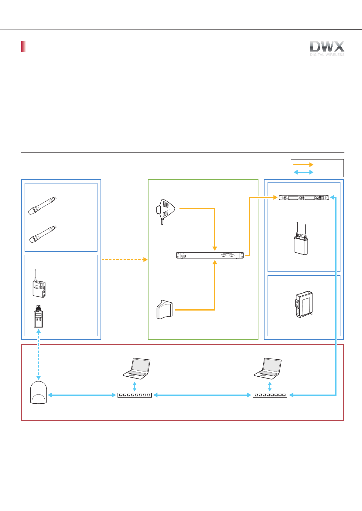
DWX refers to Sony’s new digital wireless microphone system. The DWX series reflects Sony’s extensive expertise in
professional microphones and sound design. It represents a successful blend of Sony know-how, wireless technology
renowned for stability, and cutting-edge digital audio technology.
In addition to realizing the high sound quality possible with a digital system, the DWX series supports multi-channel
simultaneous operation, encrypted transmission, and metadata transmission for monitoring the status of multiple
transmitters. Using a main link and a separate additional link, remote control of transmitters from the receiver is also
possible. With its many advanced features, the system has the potential to revolutionize the workflow of professional
applications.
System Configuration Example (Conceptual Diagram)
What is DWX?
4
What Is WiDIF-HP?
WiDIF-HP (WiDIF: Wireless Digital Interface Format, HP: High Profile) is a wireless digital audio interface format developed
by Sony.
It enables highly secure transmission with high sound quality and low system latency, and supports simultaneous multi-
channel operation.
High Sound Quality Wireless Transmission
Digital Wireless Outline
WiDIF-HP uses 24 bit/48 kHz sampling, resulting in superb sound that surpasses
CD quality. Dynamic range of more than 106 dB, wide frequency response
of 20 Hz to 22 kHz, and a low system latency of 3.4 ms** ensure excellent
performance. Additionally, there is no compander, resulting in faster response
than is possible with conventional analog wireless systems.*
* Unless otherwise specified, this refers to analog wireless systems that include a compander.
WiDIF-HP Specifications
Sampling frequency 48 kHz
Quantization 24
Frequency response 20 Hz – 22 kHz
Dynamic range 106 dB typ. (A-weighted)
THD 0.03% or better
Occupied bandwidth 192 kHz or less
Modulation principle π/4 Shift QPSK
Audio latency 3.4 milliseconds **
** When DWM-01, DWT-B01, and DWR-R01D are used in
combination. When analog output is combined with the
DWR-S01D, the latency rating is 3.6 milliseconds.
bit
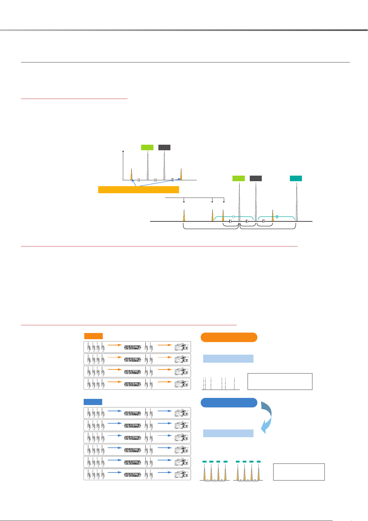
Simultaneous Multi-Channel Operation
Because WiDIF-HP is highly resistant to interference, about 50 percent more channels can be operated simultaneously, compared to
analog systems.
Analog Wireless System
Intermodulation free special channel allocation is necessary.
Digital Wireless System (WiDIF-HP)
Equally spaced easy channel allocation is available.
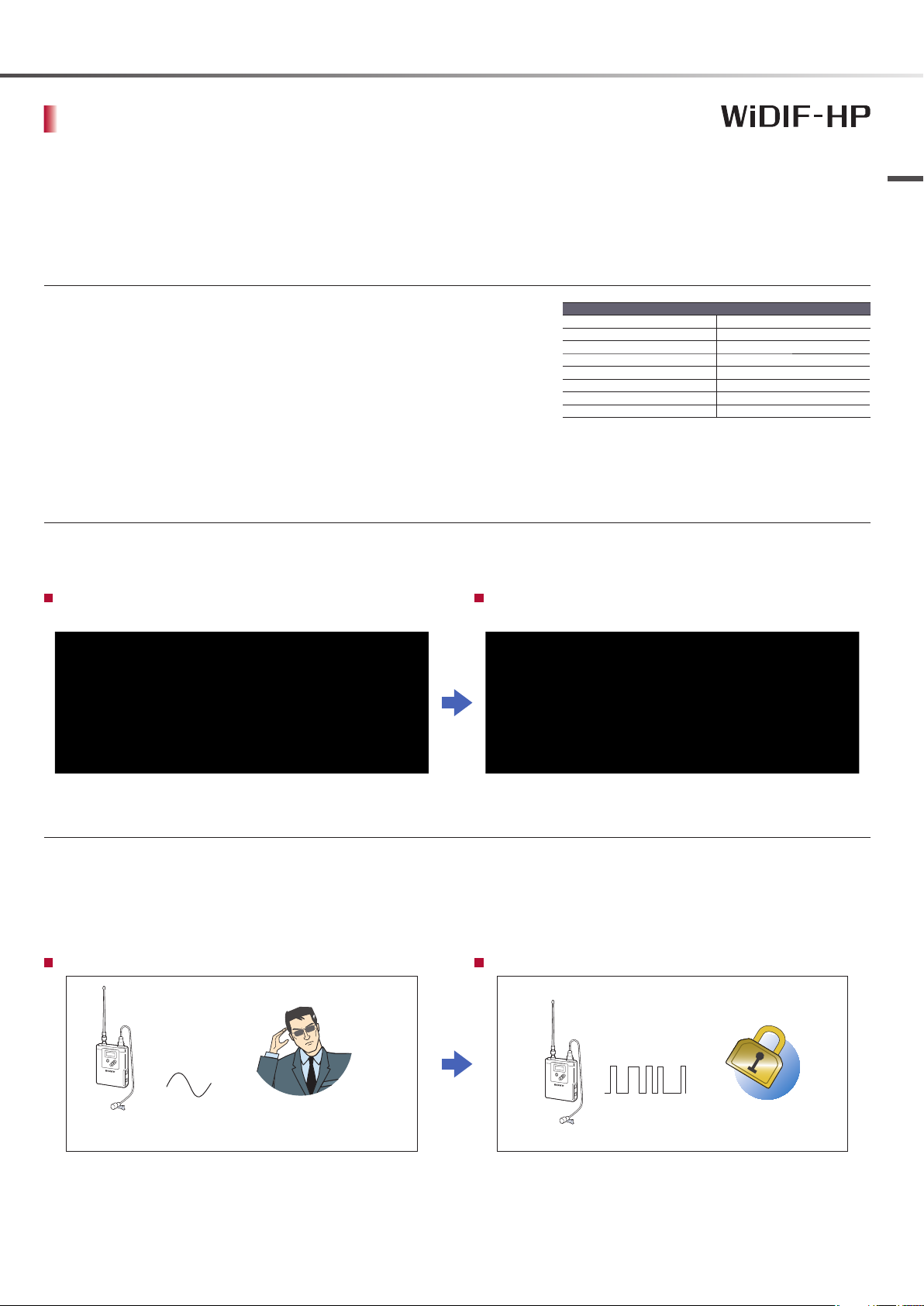
Encrypted Transmission Provides Security
Security is an important requirement for wireless systems handling the transmission of audio signals. In an analog wireless transmission
system, the transmitted audio signal is at risk of being intercepted by a receiver of an outside system. When using FM modulation,
audio signals can be received by anyone with the right equipment and some technical knowledge. By contrast, the digital audio
wireless transmission system transmits encrypted audio data, which mitigates the risk of such interception and provides highly secure
transmission for even the most critical applications.
Analog Wireless System Digital Wireless System (WiDIF-HP)
FM-modulated
audio signal
The risk of being intercepted by
a receiver of an outside system.
Digitally modulated
coded audio
Encrypted data
What Is WiDIF-HP?
5
Digital Wireless Outline Tec
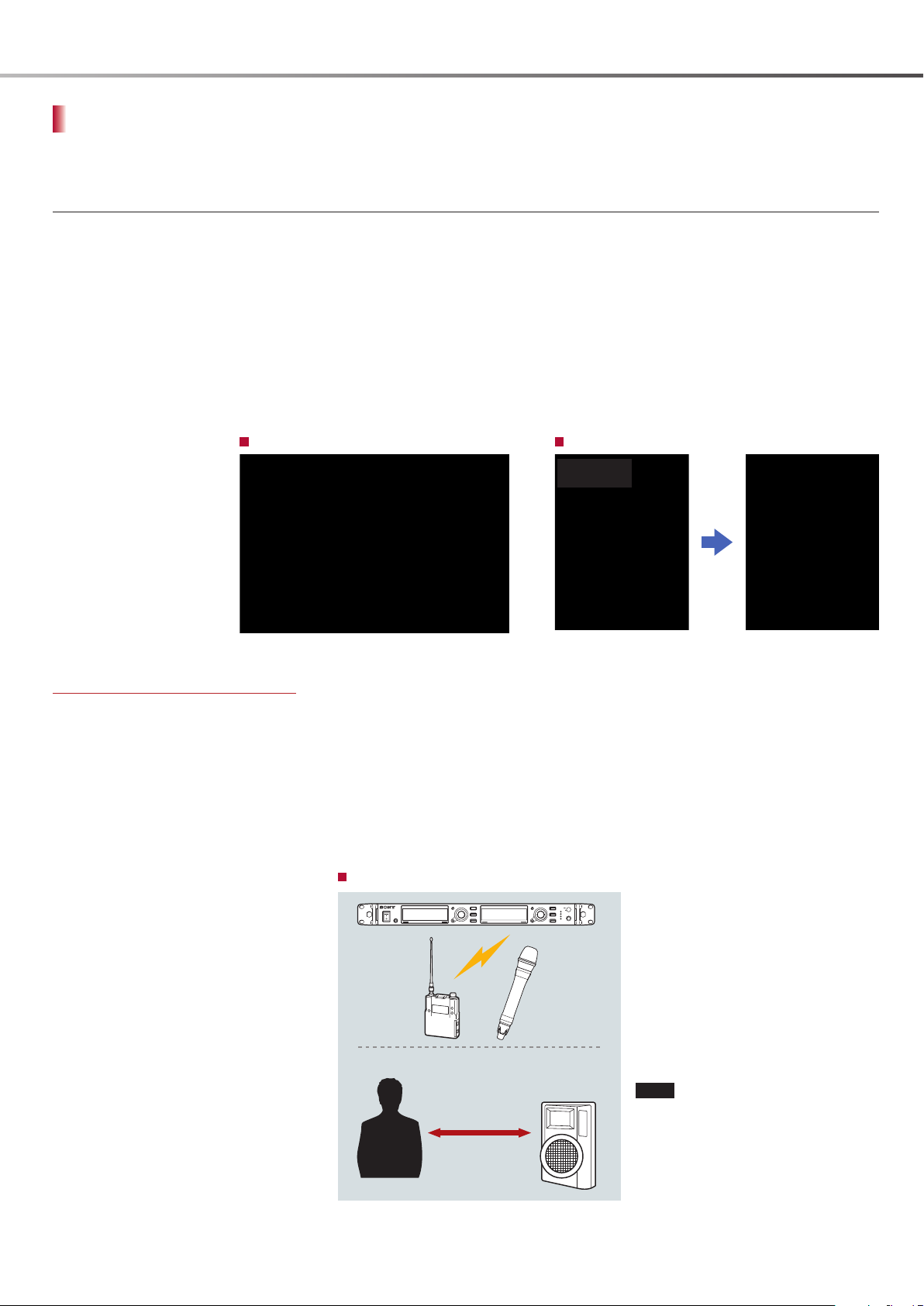
What Is Cross Remote?
Cross Remote is a system that allows transmitters to be monitored and controlled from a receiver and the Wireless
Studio control software installed on a computer connected to the receiver. For example, the settings of a transmitter
worn under clothing can be easily changed over the wireless link.
Cross Remote Functions
Monitor function
Allows you to monitor transmitter setting and status
information sent as metadata in WiDIF-HP format. Monitoring
can be performed on the receiver display, camcorder menu
screen, or multiple computers on which Wireless Studio is
installed that are connected to the network.
Control function
Allows remote control of the transmitter from the receiver and
Wireless Studio application via a 2.4 GHz band IEEE802.15.4
wireless communication standard that is separate from the
main communication line of the UHF. This is done without
affecting the battery life, audio quality, and other features
of the wireless microphone. Nearly all of the parameters of a
transmitter including those for the attenuator, low-cut filter,
power, and frequency can be controlled from the receiver.
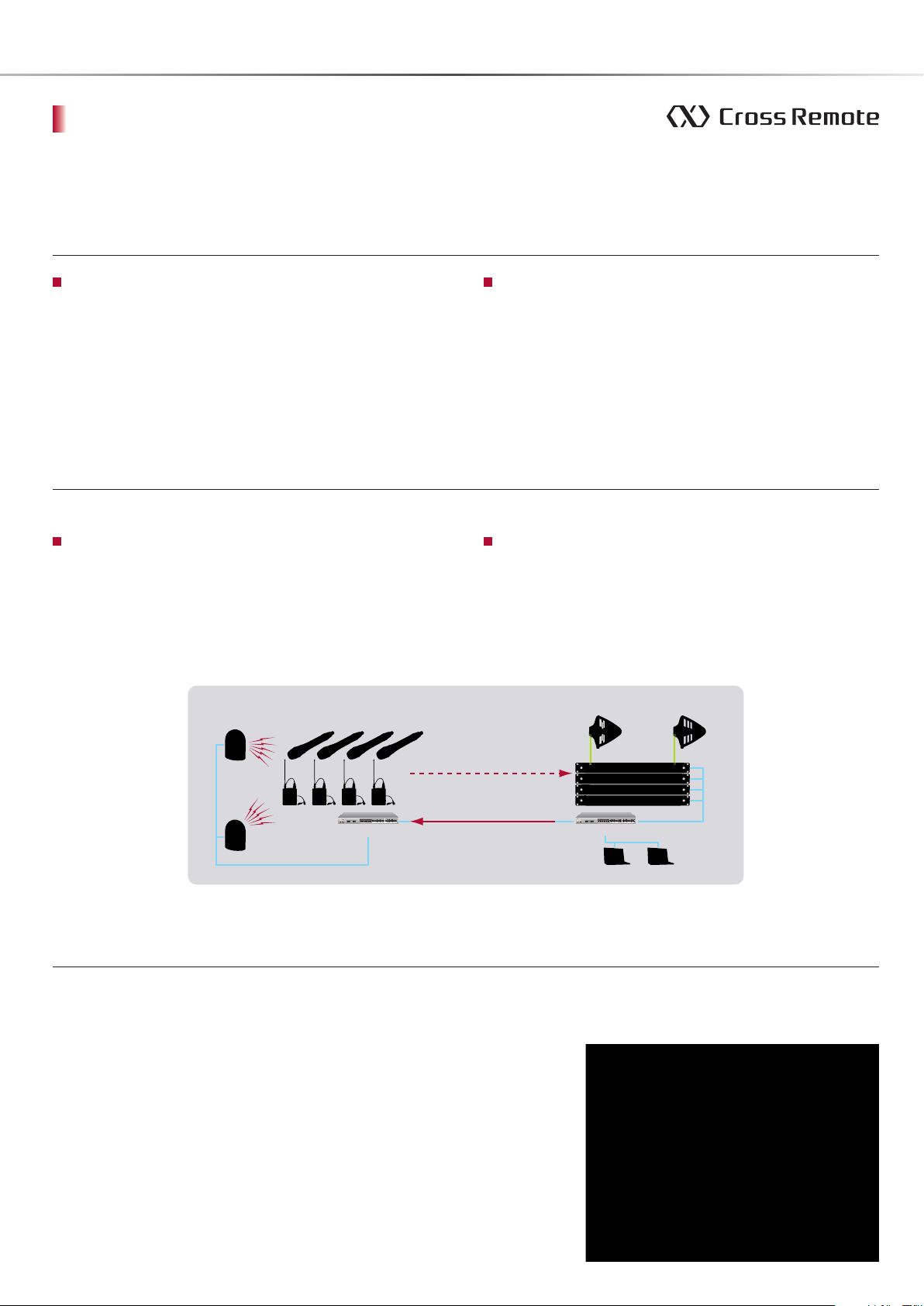
Scalable Wireless Remote Control System
Two types of wireless remote control systems can be configured, to fit the system size and requirements.
ST mode (Standalone mode)
Transmitter and receiver communicate directly in a one-onone configuration.
When the receiver is placed within a main link service area,
Cross Remote can be used within a range of about 10 meters
from the receiver. To control more than six transmitters, the NT
mode system should be used.
The DWR-S01D can be used as a receiver only in ST mode.
Conguration for NT mode
RMU-01
DWM-01
NT mode (Network mode)
Transmitters and receivers communicate via the Remote
Control Unit RMU-01 connected to a network.
One remote control unit can control up to 82 transmitters,
which allows network-based system management regardless
of receiver location. The service area range is about 10 meters
from the control unit.
AN-01
Meta Data
Control Data
on 2.4GHz
LAN Cable
DWT-B01
Stage Control Room
on WiDIF-HP
Control Data
on Ethernet
Control Software Wireless Studio
Wireless Studio is a dedicated software application supplied with the Digital
Wireless Receiver DWR-R01D.
Wireless Studio can be used both in ST mode and NT mode.
Wireless Studio provides the following functions.
Monitor and control up to 82 transmitters simultaneously.
Display the status of the receiver and remote control unit, in addition to that of
the transmitter, on the computer monitor.
Save configuration data and monitor setting data. Return configuration data
to an earlier state.
Create an error log, which can be useful, for example, in identifying the cause
of reception problems.
DWR-R01D
Ethernet HubEthernet Hub
PC
Status Monitor & Parameter Control
BNC Cable
LAN Cable
What Is Cross Remote?
6
Technology
WiDIF-HP Technology
A new high-profile format for the digital audio interface on UHF – WiDIF-HP -- has been developed for the DWX series.
This section provides further details on WiDIF-HP technology.
WiDIF-HP Technology Outline
A digital audio wireless transmission system handles audio after the analog signal has been converted into digital form by an A/D
converter.
In conventional analog wireless systems, the compander providing compression and expansion is a key component for enabling wide
dynamic range. The compander system uses complex analog circuitry for maintaining sound quality and response characteristics.
However, this analog system requires advanced techniques to keep performance levels constant, because analog circuits are subject
to the performance instability and adjustment tolerances of parts.
By contrast, the digital audio wireless transmission system is free from such instabilities as it does not require a compander system. In
short, digital audio wireless transmission is an optimum system to transmit high-quality audio signals without deterioration.
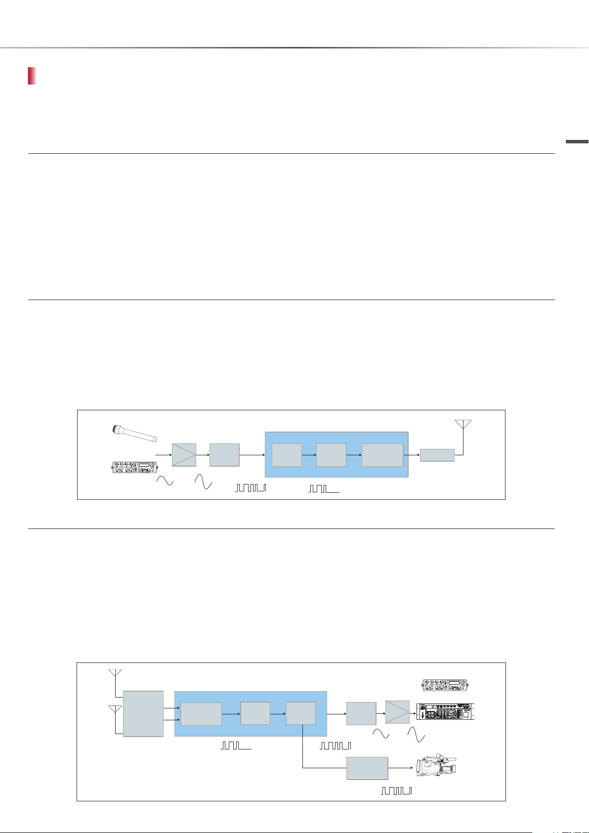
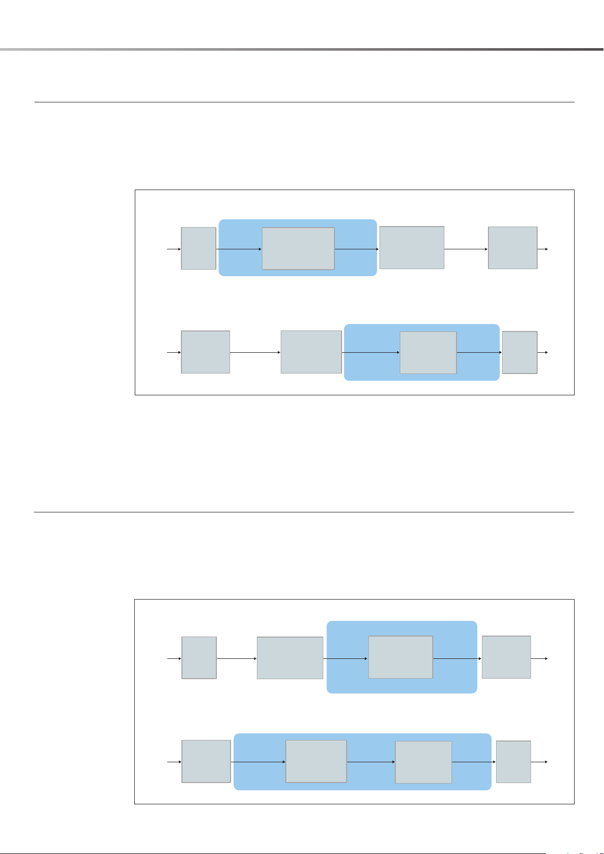
Transmitter
The transmitter in the digital audio wireless transmission system digitizes analog audio signal inputs from microphones and mixers and
then wirelessly transmits them as a digital signal. This section describes the processes that occur within the transmitter.
An analog audio signal is first amplified in the amplifier and digitized in the A/D converter. The codec then applies data reduction
techniques to the digital signal from the A/D converter and transcodes it into a digital bit stream with a lower bit rate. In the channel
coding section, sync data and error processing data required for wireless transmission are added to the audio data, and the resulting
data are encrypted. The digital modulator generates the π/4 QPSK modulation signal used to transmit the channel coded digital stream
over the digital wireless link. The modulated signal is supplied to the RF block which amplifies the modulated carrier to the power level
required for transmission.
Microphone
Amp.
A/D
24 bit
48 kHz
Full digital processing
CODEC
Channel
Coder
Digital
Modulator
RF Block
Technology
Mixer
Digital modulation
Receiver
Upon receiving the modulated carrier wave from the transmitter, the receiver reproduces the digital audio signal and outputs it as either
an analog or digital signal to audio equipment such as an audio mixer or a power amplifier. This section describes the processes that
occur within the receiver.
In the RF block, the received signal is digitized by the A/D converter. Similar to the transmitter, three main processes are then performed
in the signal processing block: digital demodulation, channel decoding, and codec processing.
After receiving the signal from the RF block, the digital demodulator reproduces the digital stream that was channel coded at the
transmitter. Then the channel decoder performs synchronization, decryption, error processing, and audio data extraction. The codec
expands the signal that was data reduced to a low bit rate in the transmitter and reconstitutes the digital audio signal. The reconstituted
digital audio signal is routed through the D/A converter and amplifier to be output as an analog audio signal or as a digital signal
corresponding to standard audio interface specifications such as AES/EBU.
Mixer
RF Block
Digital
Demodulator
Full digital processing
Channel
Decoder
CODEC
24 bit
48 kHz
Amp.
D/A
AES/EBU
Camcorder
WiDIF-HP Technology
7
Technology
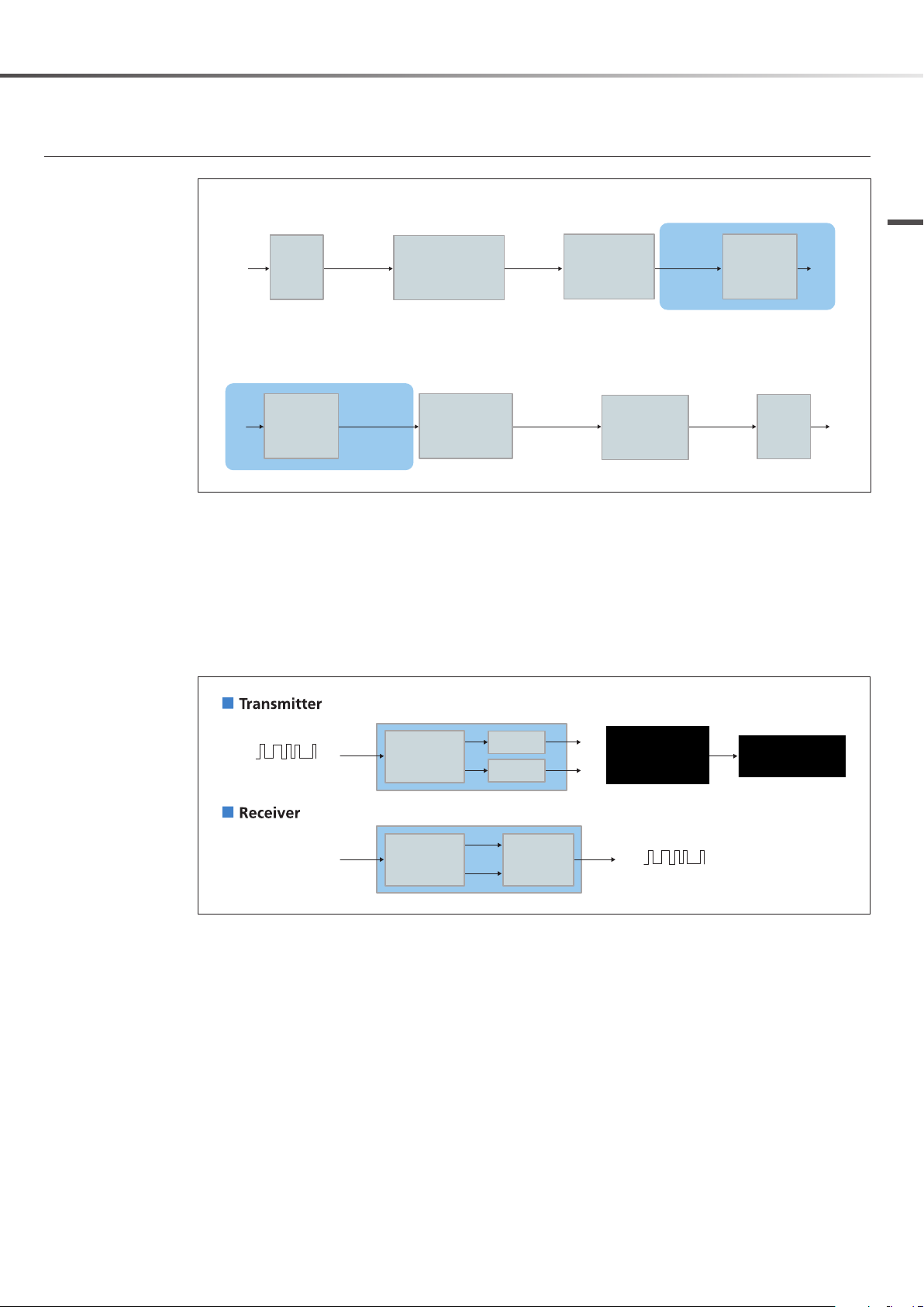
Sony’s Proprietary WiDIF-HP Codec
In the wireless system, audio signals have to be transmitted within a limited wireless bandwidth. Transmitting
the highest possible quality audio in this limited bandwidth is the major issue for wireless microphone
development. In addition, low-latency audio transmission is another requirement of microphone applications.
To transmit the best quality audio within limited bandwidth, Sony developed a digital wireless transmission
system that employs a proprietary WiDIF-HP codec, which realizes both outstanding sound quality and low
latency.
Transmitter
24 bit
@48-kHz fs
AF
A/D
1152 kb/s 192 kb/s
Receiver
RF
Digital
De-modulator
The WiDIF-HP codec is characterized by the following key features.
Outstanding sound quality with 24-bit/48-kHz sampling
Low latency
Secure transmission
The Sony digital audio codec achieves an optimum balance between sound quality, bit rate, and latency,
while having the redundant bit assignment necessary for wireless transmission.
De-modulated
Channel Coding and Decoding
Data
CODEC
Down Sampling
&
Bit Compression
Channel Decoding
Audio Data
Decripted
Audio Data
Channel Coding
CODEC
Up Sampling
&
Bit Expansion
Encrypted
&
Packetized
Data
24 bit
@48-kHz fs
1152 kb/s
Digital
Modulator
D/A
RF
AF
In order to ensure high quality audio signal transmission within the given bit rate limits, WiDIF-HP employs
synchronization technology to keep the error count as low as possible, along with error processing technology
that minimizes the risk of noise when an error occurs. These techniques were developed and optimized using
extensive simulation and field testing programs covering all wireless system operation aspects such as RF
signal attenuation, Doppler effect, RF reflections, and more. Signal encryption is also handled at the coding
stage.
Transmitter
24 bit
AF
@48-kHz fs
A/D
1152 kb/s 192 kb/s Packetized
CODEC
Down Sampling
&
Bit Compression
Audio Data
Channel Coding
Encrypted
&
Data
Digital
Modulator
RF
Receiver
24 bit
@48-kHz fs
1152 kb/s
D/A
AF
RF
Digital
De-modulator
De-modulated
Data
Channel Decoding
Decripted
Audio Data
CODEC
Up Sampling
&
Bit Expansion
WiDIF-HP Technology
8
Digital Modulator and Demodulator (QPSK)
Transmitter
AF
Receiver
A/D
24 bit
@48-kHz fs
1152 kb/s 192 kb/s
CODEC
Down Sampling
&
Bit Compression
Audio Data
Channel Coding
Encrypted
&
Packetized
Data
Digital
Modulator
Technology
RF
RF
Digital
De-modulator
De-modulated
Data
Channel Decoding
Decripted
Audio Data
CODEC
Up Sampling
&
Bit Expansion
24 bit
@48-kHz fs
1152 kb/s
D/A
AF
Sony has developed a new digital modulator and demodulator that allows large-scale simultaneous multichannel operations.
In addition to benefiting from advanced RF technology know-how in the field of analog wireless transmission
systems, the digital audio wireless transmission system also incorporates a digital modulation system that is
less vulnerable to wave interference. These technologies allow highly stable wireless transmission even for a
large number of simultaneous multi-channel operations. The newly developed Sony digital modulator and
demodulator enables up to 12 channels of simultaneous multi-channel operation in a bandwidth of just 6
MHz. Using a unique algorithm optimized for wireless microphone applications, the digital modulator and
demodulator are small enough to be integrated into an FPGA for portable devices.
Digital modulator on the one-chip IC
DATA
Filter
I
Modulated signal
Mapping
Filter
Q
QPSK modulation
Digital modulator on the one-chip IC
RF
Demodulator
I
Detector
Q
DATA
WiDIF-HP Technology
9
Technology
Key Features of WiDIF-HP
This section describes the advantages of WiDIF-HP technology.
High-Quality Sound Transmission on a Par With Wired Microphones
High sound quality is the most important aspect for a wireless transmission. This is achieved through wide
dynamic range, flat frequency response, and excellent transient response performance, factors that are
essential for high-performance broadcasting and PA systems.
Analog systems make use of companders to provide the required dynamic range. However, while compander
systems have improved over time, their inherent problems with regard to sound quality and transient response
performance have not been completely solved.
WiDIF-HP technology was developed by Sony to fundamentally improve the transient response performance
and therefore further enhance sound quality. It employs 24-bit/48-kHz sampling and provides:
Wide dynamic range of more than 106 dB
Wide frequency response of 20 Hz to 22 kHz
Superb transient response performance
Frequency Response
Response [dB]
Low latency audio transmission
The second key aspect of the WiDIF-HP codec is low latency. In a digital device, signal delays can often occur
due to the sampling, synchronization and calculation process. In particular, when wireless microphones are
used for vocals or speech applications, keeping this delay short is crucial.
In a commonly used codec such as the MPEG AAC, more than 20 milliseconds are required just for decoding.
The high processing speed of WiDIF-HP provides a fundamental solution to this problem and further enhances
sound quality by realizing a total delay of only 3.4 milliseconds* over the entire path from A/D converter in the
transmitter to D/A converter in the receiver.
High-speed response approaching linear systems
Low latency of only 3.4 milliseconds* in send/receive path
Frequency [kHz]
Low latency
Dynamic Response
Analog Wireless System Digital Wireless System
(WiDIF-HP)
Key Features of WiDIF-HP
10
Total latency (A/D to D/A): 3.4 msec.*
Converted to spatial distance:
1.2 m
* This is the combined latency of the Digital Wireless Microphone DWM-01, Digital Wireless Transmitter DWT-B01, and Digital Wireless
Receiver DWR-R01D.
When analog output is combined with the Digital Wireless Receiver DWR-S01D, the latency rating is 3.6 milliseconds.
Note
When digital mixers or similar
equipment are used along with the
digital wireless system, their latency
values will be added. It is therefore
necessary to consider the overall
latency of the system.
Stable Wireless Operation Highly Resistant to Interference
CH 4CH 2 CH 3CH 1CH 1
FM modulation
Digital modulation
Spectrum
Spectrum
Analog system
usually needs
D/U > 40 dB
D/U > 20 dB
Error Free
Desired
Undesired
Desired
Undesired
* D/U ratio: Desired/Undesired ratio
Compared to conventional analog systems, the DWX series employing the WiDIF-HP format provides
significantly better rejection of noise, third-order intermodulation, same-frequency interference and other
forms of interference. The improvement is on the order of 20 dB or more (more than 10 times better in terms of
reception voltage level). This results in improved operation stability.
Analog system
The D/U (Desired/Undesired) signal ratio will be the S/N ratio of the demodulated audio signal. Because
interference will be reproduced as noise, the higher the undesired signal level, the higher the noise will be in
the modulated signal. Typically, analog systems require a D/U signal ratio of 40 dB or more.
Digital wireless system
Provided that there are no errors, the audio signal quality will not be degraded. In the Sony digital wireless
system, an error does not occur provided the D/U signal ratio is 20 dB or more. Therefore sound quality will not
be impaired as long as this condition is met.
Technology
The Sony DWX series of digital wireless microphones employing the WiDIF-HP format provides interference
rejection that surpasses conventional analog systems by 20 dB or more (more than 10 times better in terms of
reception voltage level), resulting in improved operation stability.
Key Features of WiDIF-HP
11
Technology
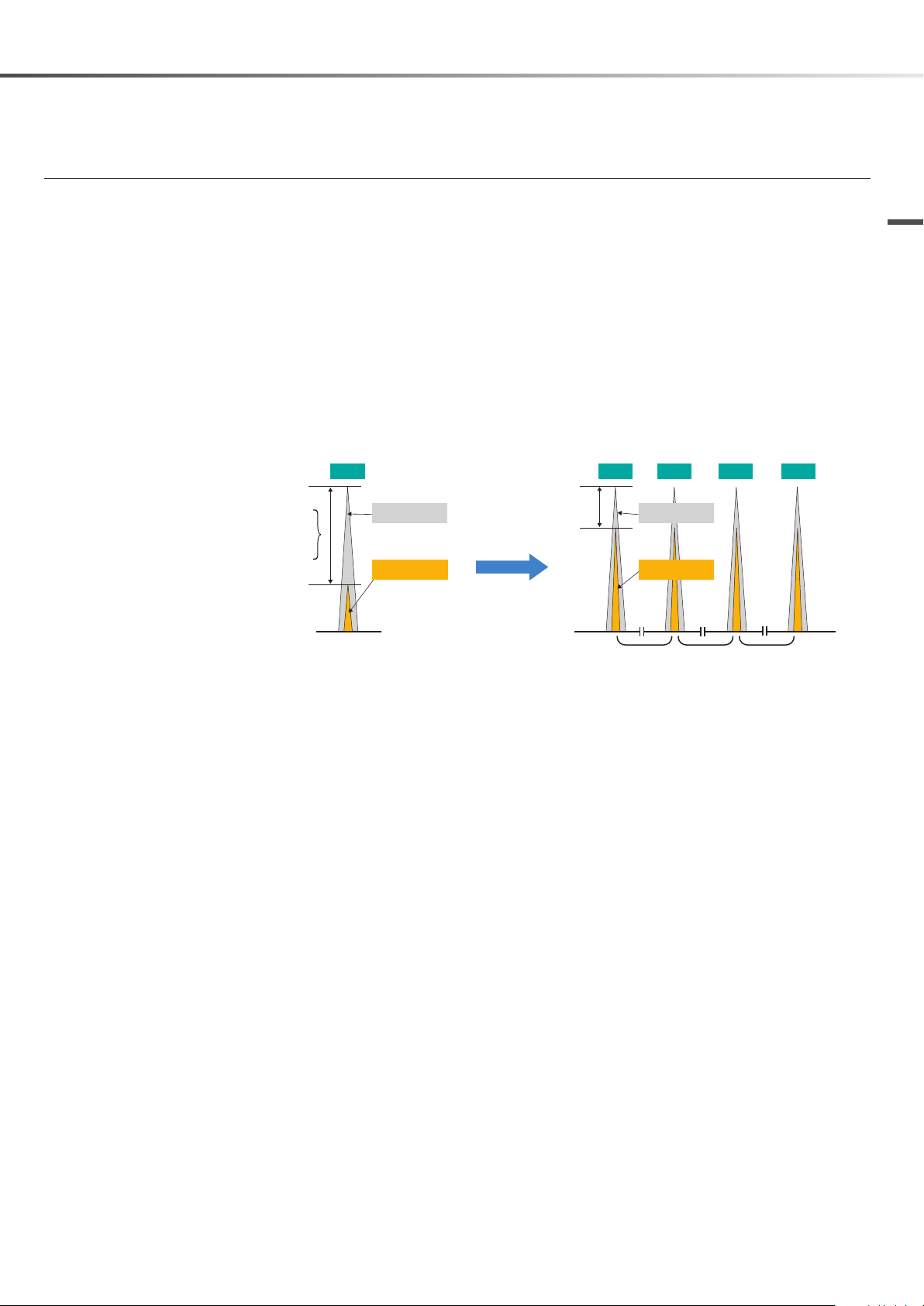
Simultaneous Multi-Channel Operation
With WiDIF-HP, the number of transmitters that can be used within the same band frequency is 1.5 times that of
an analog system, allowing for greater operability.
RF and third-order intermodulation
The RF related circuit design is an important aspect for realizing multi-channel operation. In wireless systems
with multiple channels, the intermodulation that is generated in the RF amplifier of the transmitter/receiver
often causes interference between the wireless channels. The RF block of an analog wireless system must be
designed carefully to deal with intermodulation. However, intermodulation cannot be eliminated completely,
either in an analog or digital system, as long as the RF part is composed of analog circuits.
RF spectrum
CH 1 CH 2
Third-order intermodulation signals will occur
at 639.500 MHz and 641.000 MHz
CH1: 640.000 MHz
CH2: 640.500 MHz
Frequency
CH 1 CH 2 CH 3
Third-order intermodulation signals
Wireless channel cannot be allocated
due to the intermodulation noise
Frequency
CH 1 & 2CH 1 & 2CH 2 & 3CH 1 & 3
Why are digital wireless systems advantageous to simultaneous multi-channel operation?
In an analog system, the D/U (Desired/Undesired) signal ratio will be the S/N ratio of the demodulated audio
signal. The higher the undesired signal level, the higher the noise will be in the modulated signal. Typically,
analog systems require a D/U signal ratio of 40 dB or more.
In the Sony digital wireless system on the other hand, an error does not occur provided the D/U signal ratio
is 20 dB or more. Therefore sound quality will not be impaired as long as this condition is met. The digital
wireless system provides interference rejection that surpasses conventional analog systems by 20 dB or more,
and is therefore much less prone to problems caused by intermodulation and is more efficient in handling
frequencies within a limited frequency range.
Application Example: Reality TV Show Production
Frequency environment: Clear channels are TV33, TV42, and TV55 only.
Key Features of WiDIF-HP
12
ANALOG
DIGITAL
TV33: 8ch, TV42: 8ch, TV55: 8ch
TV33 4ch TV55 2ch
TV33 4ch TV55 2ch
TV42 4ch TV55 2ch
TV42 4ch TV55 2ch
TV33: 12ch, TV42: 12ch, TV55: 12ch
TV33 4ch TV55 2ch
TV33 4ch TV55 2ch
TV33 4ch TV55 2ch
TV42 4ch TV55 2ch
TV42 4ch TV55 2ch
TV42 4ch TV55 2ch
Total 24 channels
4-camcorder system
Total 36 channels
6-camcorder system
CH 4CH 2 CH 3CH 1 CH 12CH 10 CH 11CH 9
...
Intermodulation free
special channel allocation
Equally spaced easy
channel allocation
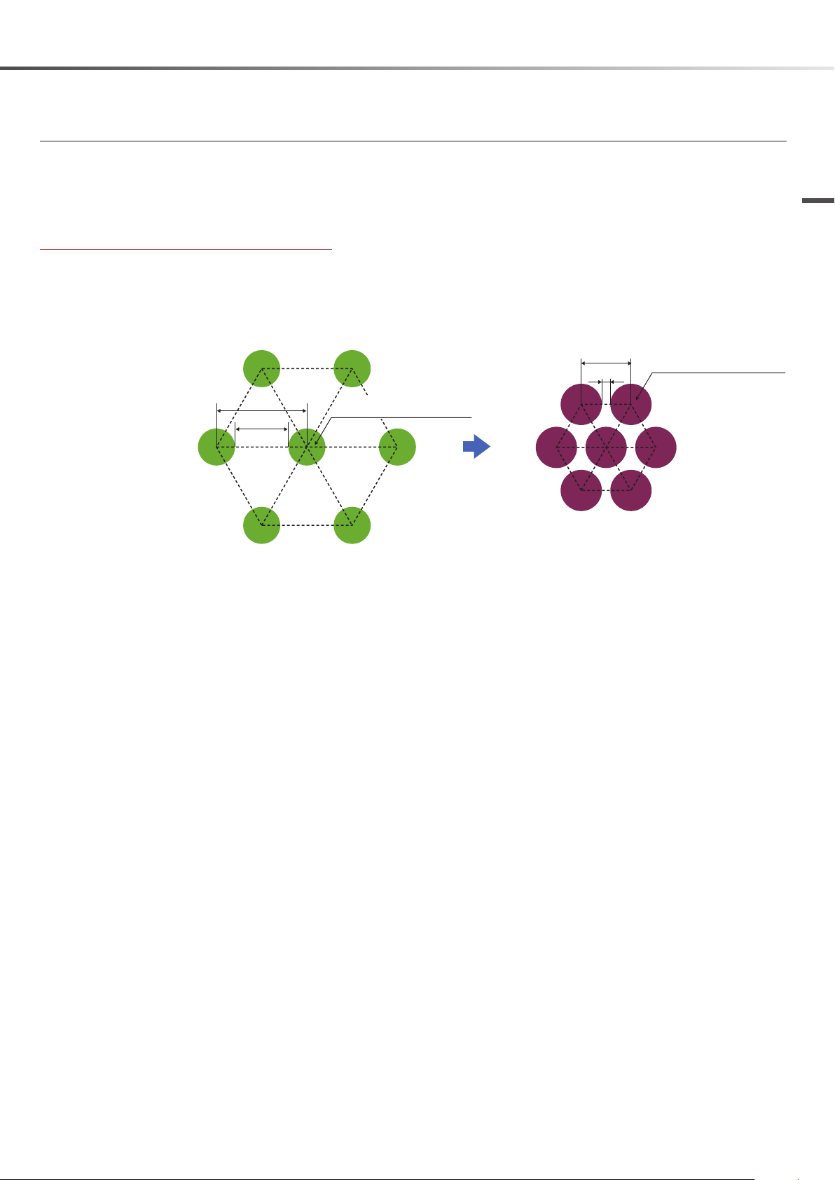
Common Frequency Reuse Configuration
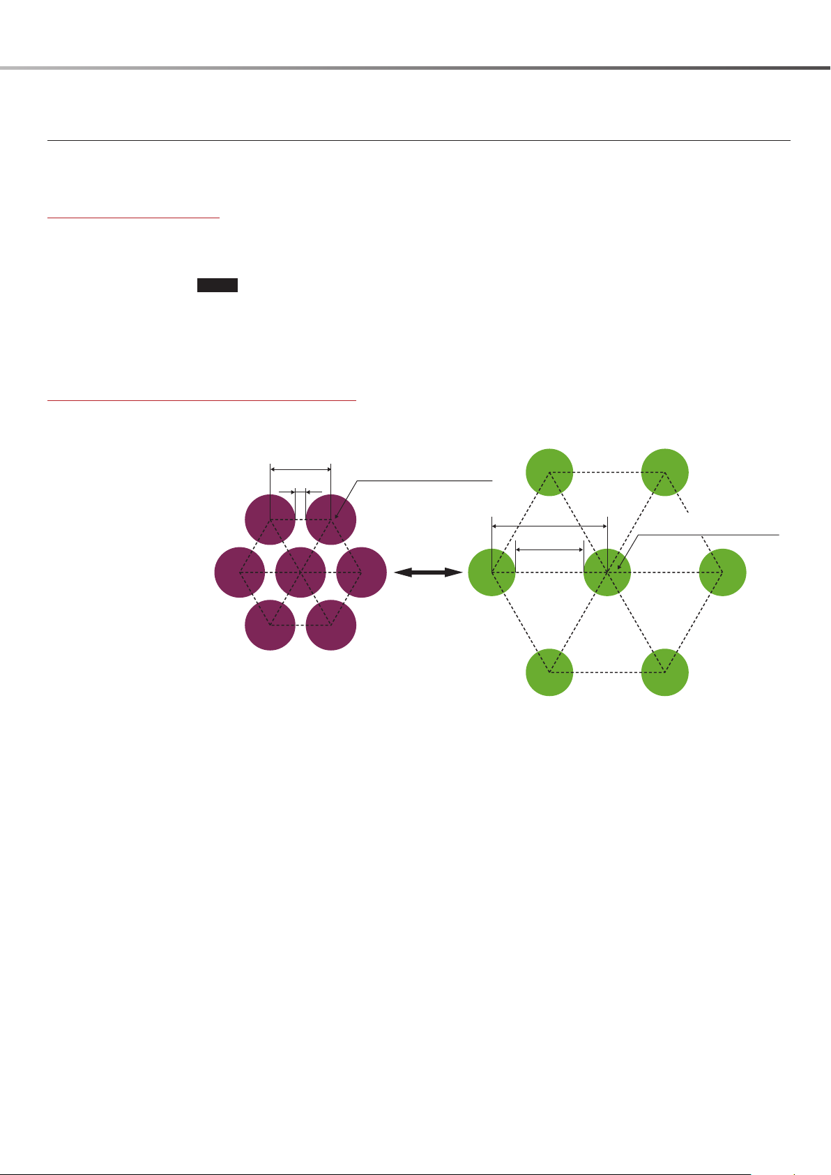
In a digital wireless system, the minimum distance for reusing a common frequency is one sixth of an analog
setup. Compared to an analog system or a mixed analog/digital system, the digital wireless system can
be configured for a three times bigger operation area which facilitates efficient use of space in convention
centers for trade fairs and similar applications.
Common frequency reuse area distances
In digital wireless systems, the minimum distance is one sixth of an analog wireless or mixed analog/digital
setup. (With 10 mW output)
Technology
Analog wireless system, or mixed analog/
digital system
Minimum area distance: 180 meters
300m
180m
Analog wireless system operation
area (radius 60 meters)
Digital wireless system
Minimum area distance: only 30 meters
180m
30m
Digital wireless system operation
area (radius 60 meters)
Key Features of WiDIF-HP
13
Analog wireless system Digital wireless system
(WiDIF-HP)
FM-modulated
audio signal
Digitally modulated
coded audio
The risk of being intercepted by a
receiver of an outside system.
For condential communication,
WiDIF-HP provides two
communication modes:
1) Secure key mode
2) Password mode
Technology
Encrypted Transmission
In an analog system, the frequency-modulated (FM) audio signal can be received by anyone with the right
equipment and some technical knowledge. By contrast, a digital system allows the use of encryption to make
the wireless transmission secure. The signals cannot be decoded by a conventional wideband receiver.
This makes it easy to maintain confidentiality for conference rooms, live performance venues and other
applications where strong measures against interception are required.
The Sony digital system offers the choice between a secure mode using encryption keys, and a password
mode where a secure group comprising multiple transmitters and receivers can be created.
Secure key mode
This is a one-on-one arrangement where the encryption key generated by the transmitter is used for a single
transmitter/receiver pair only. The mode provides highly secure strong encryption.
Password mode
A password that can be freely specified is set for a number of transmitters and receivers, and only
equipment using that password can communicate with each other. Connection to equipment without the
password set is blocked, resulting in secure operation.
Application example: broadcast station
All pieces of equipment used by the station are assigned the same password, allowing secure operation by
staff without having to worry about complicated setup procedures or information leaks. It is also possible to
broadcast audio from one transmitter to multiple receivers. Besides applications in the broadcasting sector,
this kind of system is also suitable for example for government and other public offices where information must
be transmitted securely.
Notes
Encrypted transmission does not guarantee 100% confidentiality.
Changing the password on a regular basis is recommended.
Key Features of WiDIF-HP
14
Metadata Transmission
Along with the audio signal, comprehensive information about the transmitter is sent as metadata, including
audio input level, battery status, attenuator setting, etc. This enhances operation convenience, since the
transmitter status can be monitored in any of the following ways:
On the display of the receiver
In the viewfinder of the camcorder (when using a slot-mounted camcorder; receiver information can also
be monitored)
In Wireless Studio (a dedicated software application supplied with the Digital Wireless Receiver DWR-R01D)
Metadata transmission principle
Send comprehensive information
about transmitter
Normal information display Transmitter status display example
Audio level meter
Transmitter
QL meter
RF signals
Metadata
Transmission
power indication
Receiver uses data to display
detailed status information
Receiver
Wireless remote control
Audio input level meter
condition indication
Technology
Using metadata
Display
switching
Transmission battery
indication
RF level meter Model name Input level Attenuator level Transmission battery
Example for transmitted information (with DWT-B01)
Transmitter name
Battery status
RF power setting
Attenuator level setting
Low-cut filter setting
Continuous operation time
Metadata can be used for setup of other connected equipment.
Combined delay time of transmitter and receiver can be sent to camcorder for video synchronization, etc.
indication
Key Features of WiDIF-HP
15
Technology
WiDIF-HP Precautions
This section provides information about various points to keep in mind when operating a digital wireless system.
For details, see “UHF System Configuration” (page 38).
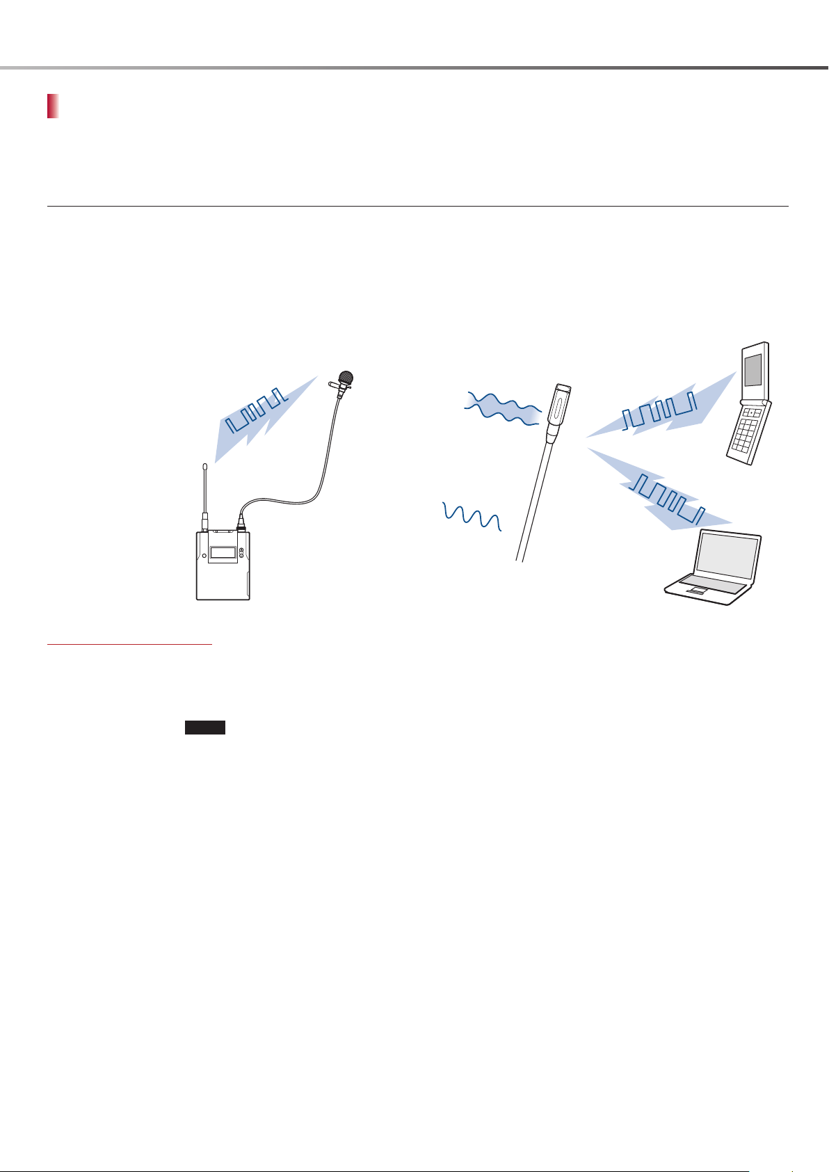
RFI (Radio Frequency Interference) Noise
WiDIF-HP performs cyclic packet transmissions similarly to mobile phones, computers, and other digital
transmission equipment.
The nonlinear devices (FETs, etc.) in the condenser microphone pick up these other RF signals, and RFI noise
may occur according to the packet format as a result. Countermeasures are therefore required. This applies in
particular to DWX transmitters set to high output (50 mW).
The RF signals emitted by
WiDIF-HP may affect the lavalier
microphone.
Noise countermeasures
Use cables with effective shielding.
Take measures to implement RF immunity of microphone unit.
Use lavalier microphones designed to be used together with digital wireless equipment that include RFI noise
countermeasures.
Notes
Dynamic microphones are typically not subject to exhibiting this type of RFI noise.
Sony professional lavalier and shotgun microphones with a suffix /9X in the model name, such as the
ECM-77BC/9X, are certified by Sony to be suitable for use with the DWX digital wireless system. Other Sony
professional microphones without a /9X in the model name may not be suitable for use with the DWX
system.
Microphones from Sanken, DPA, or Countryman include models that do not produce RFI noise and can
therefore be used with the DWX system. For details on compatible models, contact the manufacturer of
each microphone.
RFI noise may also occur due to RF signals emitted by mobile
phones, computers, and other digital equipment.
Lavalier microphone
Detection
Mobile phone signals
2.4G Wifi
WiDIF-HP Precautions
16

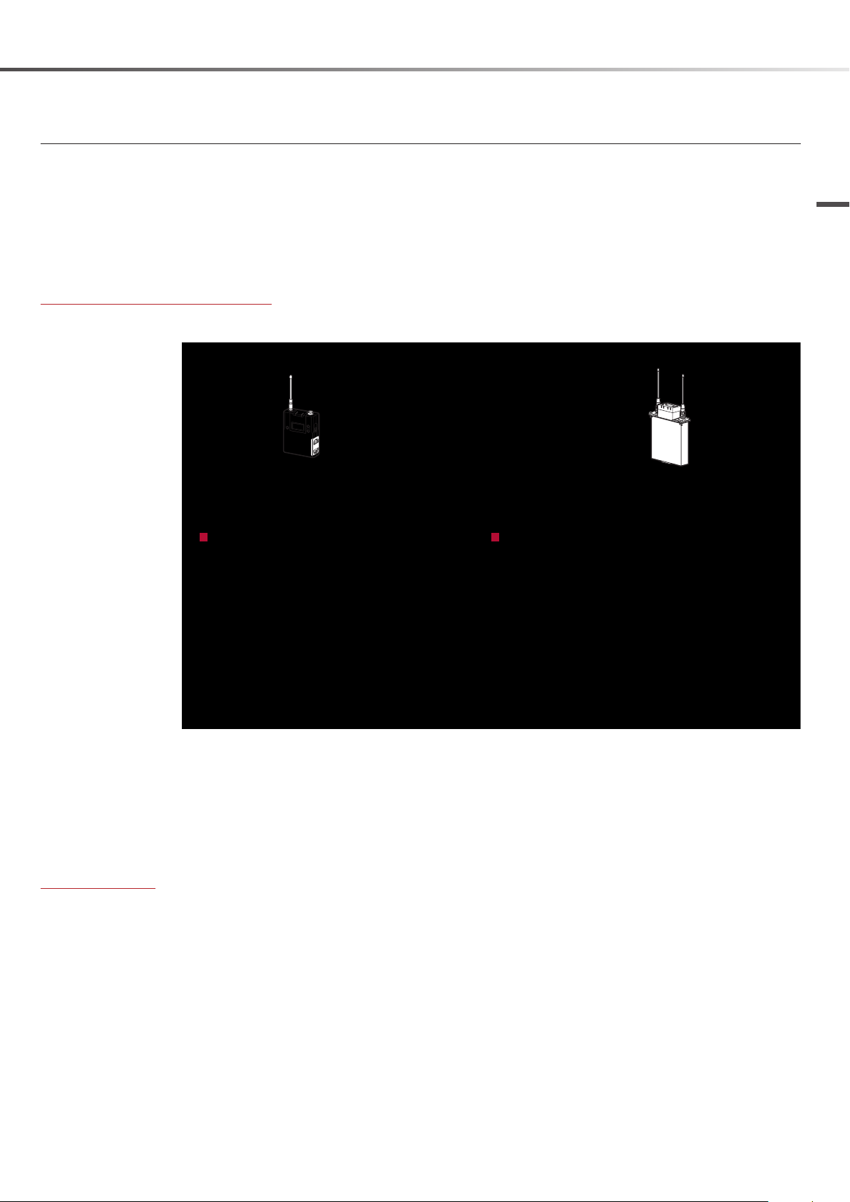
Sound Quality Degradation under Weak Field Conditions — Analog and Digital Propagation
Provided that the transmitter power is the same, the signal level at the receiver at a given distance will be the
same for a digital wireless and analog wireless system. This means that both systems can be said to have a
service area of the same size.
However, as explained in the preceding sections, the audio quality degradation behavior when field strength
becomes low is significantly different for digital wireless and analog wireless.
When compared at an equal transmitter power level, the following differences will occur as correlated to the
reception level.
There will be an area where 1) digital wireless retains high sound quality, 2) analog wireless suffers from
deteriorated audio S/N ratio.
There will be an area where 1) digital wireless starts to exhibit intermittent muting, 2) analog wireless has
lower S/N ratio but sound remains audible.
Digital
Technology
At the same power, the
propagation reach is the
same, but behavior in the
cut-off region is different.
The differences in sound quality degradation under weak field conditions may be experienced as a subjective
difference in service area size.
With WiDIF-HP, error processing has been optimized for a digital wireless system where intermittent muting
increases as the signal gets weaker. Operation patterns should be decided based on application
requirements and an evaluation of characteristics at the service area limit.
Because WiDIF-HP is tuned to maintain voice clarity as much as possible even when errors occur, evaluation
of error rates within the service area should be done using the Quality Level (QL) meter on the display of the
receiver or of the Wireless Studio application. The QL meter allows observation of transmission quality changes
over time.
Sound quality
Noise
Audio
dropout
Field strength
Analog
This graph shows a conceptual rendering.
It does not represent actual measurement
values.
Distance
WiDIF-HP Precautions
17
300m
180m
180m
180m
30m
Digital wireless system operation
area (radius 60 meters)
Analog wireless system operation
area (radius 60 meters)
Technology
Mixed Digital/Analog Systems
When digital wireless and analog wireless systems are used together, take the following points into
consideration.
Channel plan limitations
In a mixed digital/analog wireless system, channel plans designed for analog systems must be used.
Equal channel spacing applies only to fully digital wireless systems. Equal channel spacing is not available
for analog wireless systems.
Notes
Refer to Sony digital wireless system frequency lists for further details on pre-programmed groups of
frequencies built into every DWX transmitter and receiver.
Sony’s built-in pre-programmed frequency groups provide 500 kHz channel spacing for digital channel
plans D1-D9 along with analog channel plans 01-09 (containing irregular channel spacing) to ensure
compatibility with Sony analog wireless system channel plans.
Common frequency interference precaution
When operating adjacent to an analog wireless system, the minimum distance for analog wireless systems
must be observed.
Digital wireless system only
Analog wireless system, or mixed analog/
digital system
WiDIF-HP Precautions
18

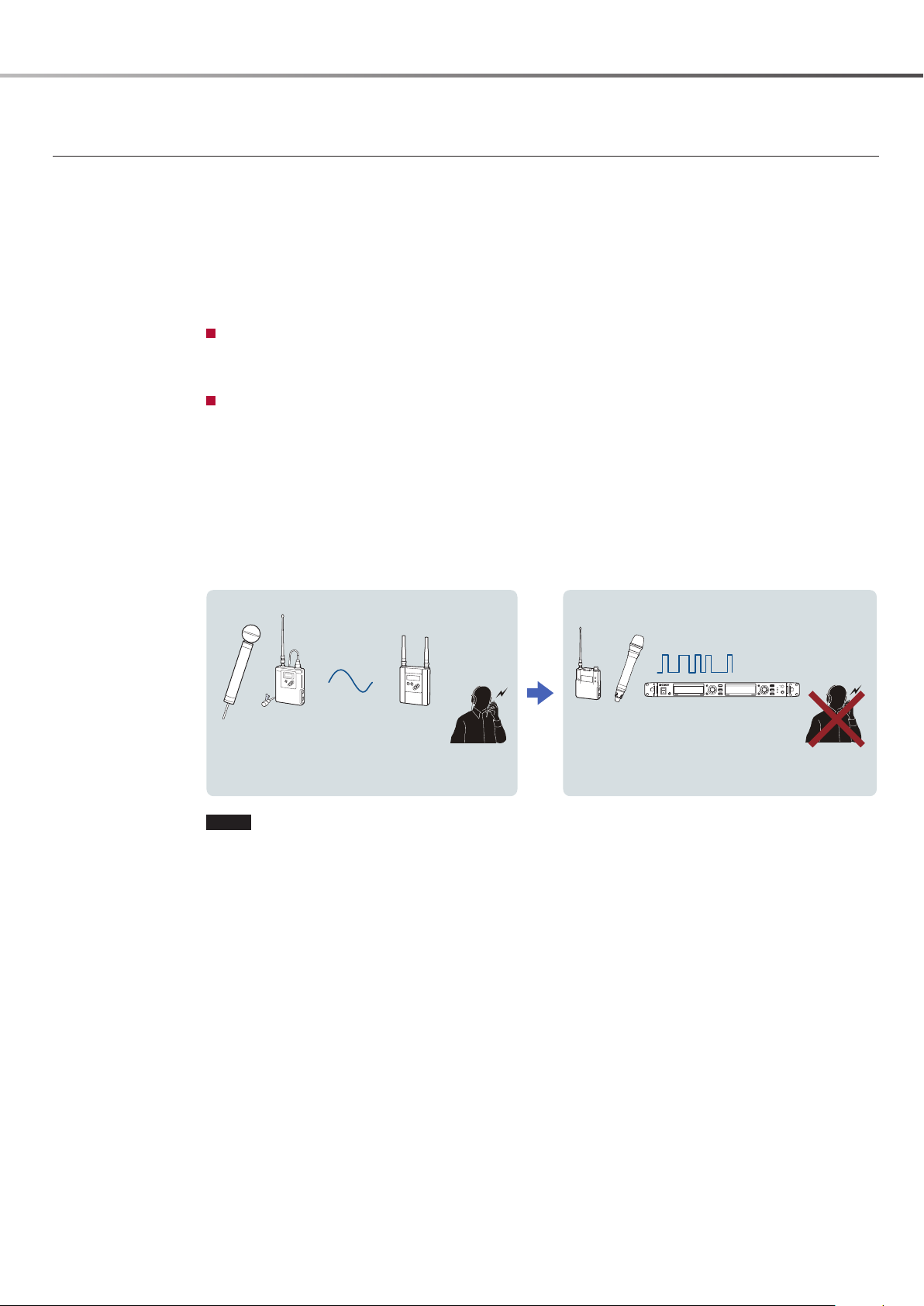
System Behavior in Case of Interference
To understand how analog and digital systems can have a mutual effect on each other in actual operation,
it is important to consider the way in which the demodulated audio signal deteriorates when interference
occurs.
Analog Analog
The stronger the interference, the higher the level of unwanted signals mixed to the audio.
This is heard as so-called beat noise, a chirping or squealing sound.
Digital Analog
As interference gets stronger, a “digital type” hiss noise will gradually be mixed to the audio of the desired
signal.
There is no beat noise typical of analog to analog interference. If the receiver has a function for detecting
noise and muting the output, the audio will eventually be cut off as the interference noise increases.
Analog Digital
Behavior is the same as for digital to digital interference.
As interference gets stronger, errors will cause intermittent audio degradation.
When interference increases further, intermittent muting will occur more frequently.
Finally, the output will be completely muted.
Digital Digital
Behavior is the same as for analog to digital interference.
As interference gets stronger, errors will cause intermittent audio degradation.
When interference increases further, intermittent muting will occur more frequently.
Finally, the output will be completely muted.
Technology
With WiDIF-HP, sound quality will not be impaired as long as the D/U signal ratio is 20 dB or more. Unlike with
analog systems, there will also be no loud beat noise in case of interference.
The rapid transition characteristics from high sound quality to muting when interference increases are the
same as for weak field reception. If the same channel must be used in adjacent areas, suitable measures
should be taken to ensure a D/U signal ratio of at least 20 dB. Such measures include maintaining minimum
distances, making appropriate settings for transmission power, and appropriate antenna installation design
and settings. The RF indicator and QL meter functions of the receiver should be used to determine the final
channel plan and equipment settings.
WiDIF-HP Precautions
19
DWR-R01D
AN-01
PC
DWM-01
DWT-B01
RMU-01
LAN Cable
Metadata transmitted via WiDIF-HP
Status information for each transmitter is sent on
respective UHF frequency
If metadata monitor function only is used, service
area is equal to UHF (sound) range
Control data sent via 2.4 GHz
NT mode
RMU-01 transmits control information for all
transmitters on network (max. 82 units)
Up to nine RMU-01 units can be used, to enlarge
service area
*Internal 2.4 GHz antenna of receiver cannot be used
ST mode
Control information is sent to currently received
transmitters (max. 2) via internal 2.4 GHz antenna
Both modes
Transmitter identifies received control data by ID
Control results are returned as WiDIF-HP metadata
Area where UHF and 2.4 GHz communication
overlaps is service area for control functions
2.4 GHz communication range has a radius of about
10 meters in a space with good line of sight
In sleep mode, WiDIF-HP is not received. Two-way
2.4 GHz communication is used for monitoring
Cross Remote protocol is expanded over
Ethernet network
Protocol is TCP/IP based
100Base-TX/10Base-T network equipment can
be used
RMU-01 used for 2.4 GHz antenna expansion
Monitoring and control with
Wireless Studio
Allows integrated system
management
Up to 6 Windows PCs are supported
Monitoring and control possible at receiver
Covers transmitters currently being received
ST mode uses the internal 2.4 GHz antenna
* Used in NT mode only.
UHF
2.4 GHz
BNC Cable
Network HUB
Technology
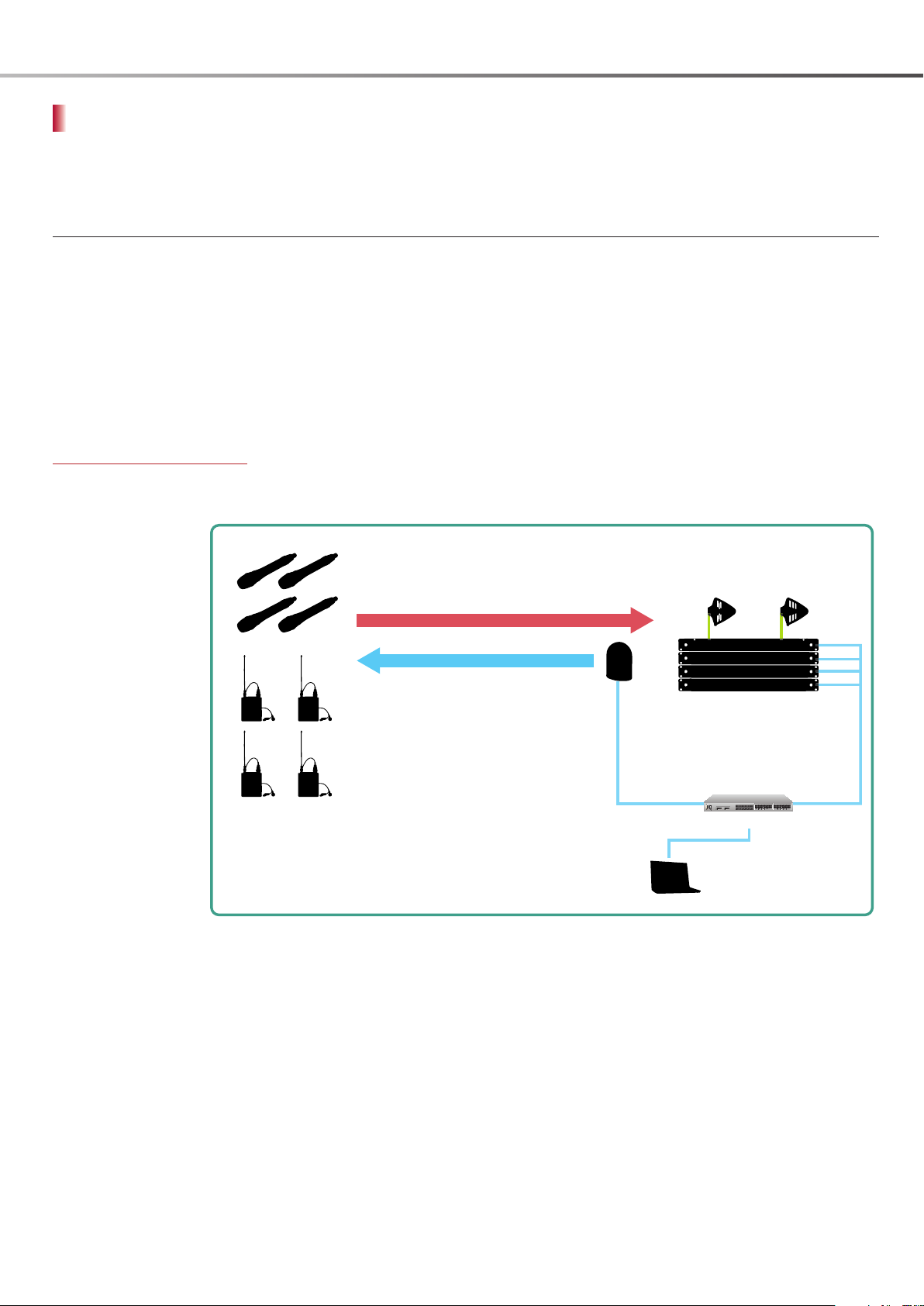
Cross Remote Technology
Cross Remote is a system that allows transmitters to be monitored and controlled from a receiver and the Wireless
Studio control software installed on a computer connected to the receiver.
Cross Remote Outline
Compared to analog wireless systems, the DWX series allows more channels to be operated simultaneously.
The Cross Remote system for remote control of transmitters from a receiver was developed to facilitate setup
and operation of large wireless microphone configurations.
Cross Remote uses an independent 2.4 GHz RF carrier (compliant with the IEEE 802.15.4 standard) to
implement remote control that is separate from the UHF main link. This allows simultaneous audio transmission
and remote control operation without affecting the battery life, audio quality and other features of the wireless
microphone system. Attenuator and low-cut filter settings as well as power, frequency and almost all other
transmitter settings can be controlled remotely. Even when the transmitter is worn concealed on the body,
Cross Remote makes it easy to change settings remotely.
How Cross Remote works
Cross Remote transmits the data described below, allowing remote monitoring and operation of the transmitter
from the receiver side.
Cross Remote Technology
20
* When using the DWR-S01D as receiver, the RMU-01 or a computer cannot be used.

Why does Cross Remote use both UHF and 2.4 GHz frequencies?
Cross Remote is a two-way communication system for transmitters and receivers that uses both UHF and 2.4
GHz frequencies to complement each technology’s strengths and advantages.
Advantages of 2.4 GHz (over using two-way UHF)
Two-way UHF would require a built-in receiver on the transmitter and would result in higher power
consumption, larger equipment size, and higher cost, making the implementation of this approach
impractical.
Because two-way UHF uses UHF channels for control, the number of channels that can be used
simultaneously is reduced. 2.4 GHz control on the other hand does not effect the number of channels
that can be used simultaneously.
Advantages of UHF (over using two-way 2.4 GHz)
UHF communication is always on. If an audio link is established, it will always reach the other party.
2.4 GHz on the other hand is not always on, in order to save power.
2.4 GHz uses common frequencies on a time sharing basis and connects only when needed.
The control signal (upstream) sends the same information to 82 units simultaneously, and status
information (downstream) can be divided into separate UHF streams.
In NT mode, up to 82 transmitters can be monitored and controlled together using RMU-01 units and
Wireless Studio. With 2.4 GHz, communicating with all 82 transmitters would take time. When using
UHF and 2.4 GHz, the combination of 2.4 GHz for upstream and UHF for downstream links results in a
communication system that realizes a smooth workflow.
2.4 GHz IEEE 802.15.4 Technology
Technology
Cross Remote uses 2.4 GHz band IEEE 802.15.4 communication technology that does not affect the band used
for digital wireless audio communication.
IEEE802.15.4 standard
IEEE 802.15.4 is a worldwide standard for close-range communication applications using the 2.4 GHz band.
Bands within the 2.4 GHz range are called ISM* bands and are widely used for microwave ovens, WiFi and
Bluetooth applications, as well as for data transmission in medical institutions and similar.
* Abbreviation of “Industrial, Scientific and Medical”. Frequency range allocated to wireless communication in these fields, requiring no
license to operate.
Notes
IEEE 802 is a set of network standards developed by the 802 committee of the IEEE (Institute of Electrical and
Electronics Engineers). It comprises the following standards:
802.11 Wireless LANs
802.15 Wireless Personal Area Networks (WPANs)
802.15.1 Bluetooth
802.15.3 UWB
802.15.4 Wireless Sensor Network (PAN standard with low power consumption and low transfer rate)
Reference: About ZigBee
This is a short-range wireless communication standard for domestic appliances. It uses the physical layer
interface defined by the IEEE 802.15.4 and newly defines the network layer, security service provider, and
application layer. ZigBee is not identical with IEEE 802.15.4.
Cross Remote Technology
21

.
Technology
System configuration
Application Layer:
APL Layer
MAC Layer
PHY Layer
Denes the protocols for user interaction
on the network
(pairing and address allocation).
Media Access Layer:
Denes the specications for device
interaction on the network
(error correction, ACK, resend request etc.).
Physical Layer:
Denes the wireless principles for the network
(frequency, modulation principle etc.)
Follows RF standards for various countries.
Why was IEEE802.15.4 adopted?
Among alternatives such as 2.4 GHz wireless LAN, Bluetooth, and UWB, Cross Remote has chosen IEEE 802.15.4
for the following reasons.
Very low power consumption avoids degradation of battery life for the main communication link.
Very fast wakeup from sleep state. Intermittent operation further contributes to power savings, while posing
no inconvenience for users.
Communication speed and range are suitable for control requirements.
In addition to point-to-point communications, network can be expanded, allowing control of multiple
transmitters from multiple computers.
Cross Remote uses the physical layer and MAC layer specified by IEEE 802.15.4, and defines the application
layer according to the requirements of convenient on-site use.
Notes
Why RF wireless rather than infrared?
Whereas infrared wireless becomes unusable when there are screens or other obstacles, RF wireless allows
remote control of a transmitter even when worn under clothing.
Cross Remote denes APL layer.
Determines the network conguration and pairing
method, roaming principles, and protocols.
ST mode/NT mode switching is also performed here
(Note: ZigBee also denes these specications.)
The MAC layer and PHY layer are dened
by IEEE 802.15.4.
Why 2.4 GHz band?
Among the frequencies covered by IEEE 802.15.4, namely 868 MHz, 915 MHz, and 2.4 GHz, the 2.4 GHz band
was chosen because it allows worldwide use. It is suitable as a common platform for devices to be used
globally.
Cross Remote Technology
22
Used frequencies
Ch.1
Ch.2
Ch.3
Ch.4
Ch.5
Ch.6
Ch.7
Ch.8
Ch.9
Ch.10
Ch.11
Ch.12
Ch.13
11 12 13 14NT15ST16 17 18 19NT20ST21 22 23 24NT25ST26
IEEE802.15.4
2.400 GHz – 2.4835 GHz
22 MHz 25 MHz
2 MHz
5 MHz
Wireless LAN
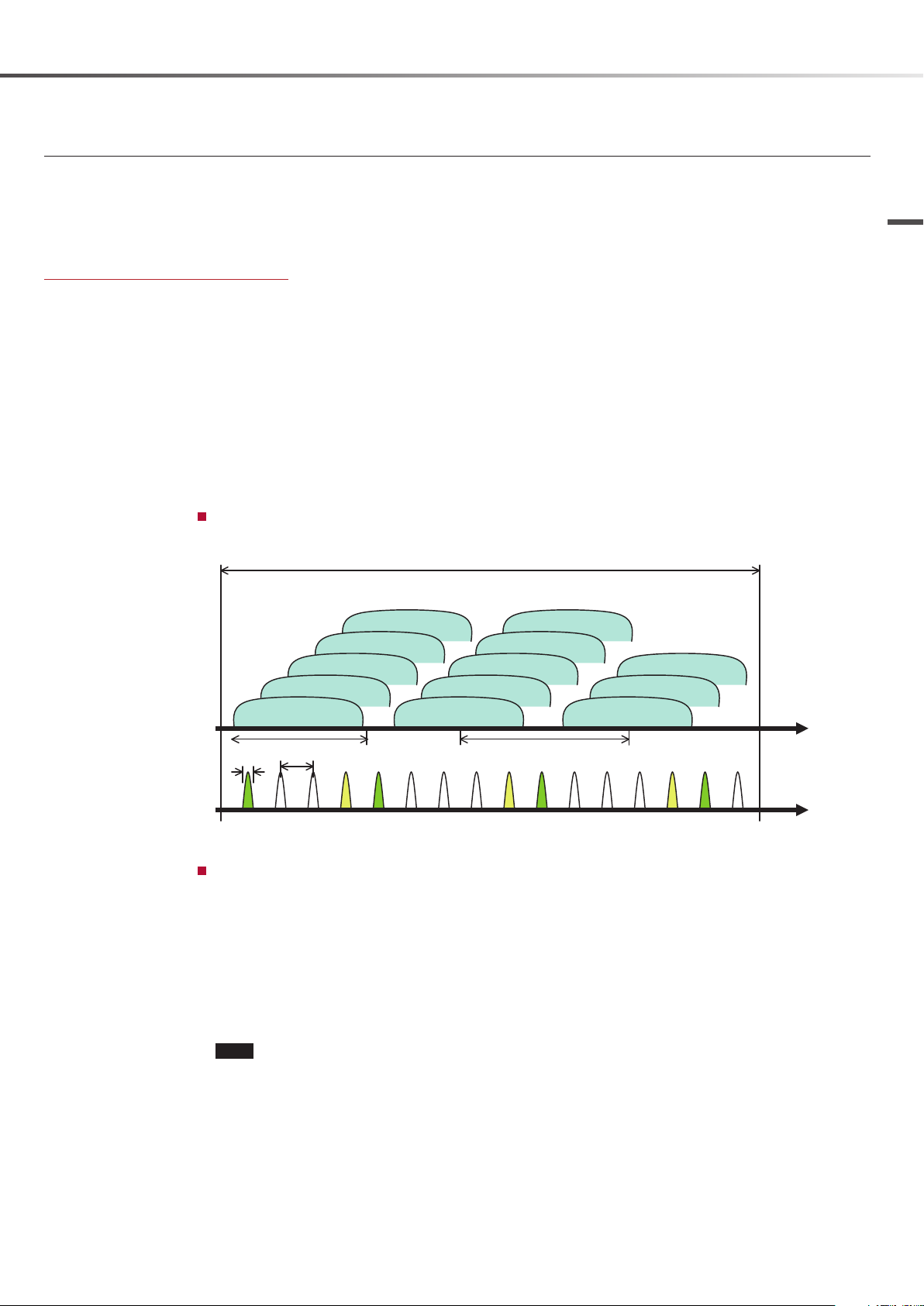
Cross Remote selects the optimal frequency for communication based on the system and the environment.
If interference is detected on a currently used frequency, the system automatically switches to another
frequency and continues communication. This assures stable operation even under congested 2.4 GHz
conditions.
Cross Remote frequency bands
IEEE 802.15.4 comprises the following specifications, but because of RF regulations, only the 2.4 GHz band can
be used worldwide.
868 MHz (BPSK, 20 kbps)
915 MHz (BPSK, 40 kbps)
2.4 GHz (O-QPSK, 250 kbps)
Cross Remote uses the 2.4 GHz band to allow identical specifications for all global regions.
The 2.4 GHz band comprises 16 channels spaced at 5 MHz, from 2.405 GHz (channel 11) to 2.480 GHz
(channel 26).
Out of these, Cross Remote uses the following frequencies.
ST mode: 2.405 GHz (11ch), 2.425 GHz (15ch), 2.450 GHz (20ch), 2.475 GHz (25ch)
NT mode: 2.420 GHz (14ch), 2.445 GHz (19ch), 2.470 GHz (24ch)
Wireless LAN and channel allocation
Channels 1, 6, and 11 are commonly used for wireless LANs.
Technology
Conditions for frequency switching
Channels are switched when the following conditions occur:
A wireless LAN starts to operate on the currently selected channel and remote control communication is
no longer possible.
Interference is detected at the receiver. The network is reconfigured.
A reset is performed, and the system starts scanning for an empty channel.
When a channel is found, the system waits for transmitter reconnection.
When the connection is interrupted, the transmitter scans all channels and looks for a reconnection
target.
When the paired equipment is found on another channel, the reconnection process is initiated.
Note
Channel switching does not necessarily occur for all types of interference.
Short, sporadic interference cannot be avoided by this technique .
Channel switching is effective for prolonged interference caused by streaming or similar operations on
the wireless LAN.
The receiver controls whether channel switching is performed. Even if subject to interference, the
transmitter does not initiate channel switching.
Cross Remote Technology
23

Technology
Pairing
Prior to being able to use the Cross Remote control functions, the transmitter and receiver must be assigned to
each other in a process called pairing. The relationship between transmitter and receiver is that of Coordinator
to Device. When NT mode is used, the Remote Control Unit RMU-01 is the Coordinator.
Pairing requirement
Because Cross Remote uses only three frequencies to control multiple transmitters (up to 82 in NT mode),
it is not possible to identify devices by frequency assignment, as for the main communication link. As the
control signal reaches all transmitters within the service area, pairing is necessary to establish which receiver is
operating which transmitter.
Control of transmitter A is intended, but
signals also reach unrelated transmitter B.
Only commands from paired
receiver A are processed.
Receiver A
Receiver B
Transmission content for pairing
Establish Coordinator/Device allocation
Exchange ID information
The MAC address is used as ID.
In NT mode, the Ethernet IP address is also registered in the transmitter.
Exchanging abbreviated ID information for communication
Sending basic transmitter information (transmitter receiver)
The following information is sent.
dB range available for attenuation
Phantom power supply present/absent, etc.
Setting the frequency (transmitter receiver)
Notes
If pairing was established in ST mode, renewed pairing is necessary when NT mode is to be used
subsequently (because the Ethernet IP address information is not registered in ST mode).
The receiver can display up to 8 candidates for pairing. As the ninth and subsequent transmitters will not
be displayed, do not set too many transmitters to pairing mode at the same time.
Signals are also received from
unrelated receiver B.
Transmitter A
Signals are received from receiver A but are
addressed only to transmitter A, and are
therefore not processed on transmitter B.
Transmitter B
Cross Remote Technology
24

Roaming
Roaming in NT mode
In NT mode, when the connection between transmitter and remote control unit is interrupted, the transmitter
automatically searches for another remote control unit to connect to.
If found, the transmitter connects to that remote control unit, and the connection to the paired receiver is
established again. This process is called roaming. The Cross Remote service area can be enlarged by using
multiple remote control units and maintaining communication through roaming.
RMU-01
Receiver
NG
Transmitter
RMU-01
Transmitter
Technology
Roaming times
When communication with connected RMU-01 is
interrupted...
...the transmitter scans all channels looking for a
RMU-01.
(The RMU-01 connected immediately prior is
assigned a lower priority. When other RMU-01 units
are found, the transmitter connects to them in the
order they are found.)
When a RMU-01 is found, a connection request is
sent.
Same sequence as during startup is performed.
When one transmitter performs roaming in a normal communication environment
The number of operation channels does not significantly change the roaming time.
1-channel system: approx. 1 second
82-channel system: approx. 1.5 seconds
When multiple transmitters are performing roaming
Time per unit x number of units (approximate calculation)
For example, when 50 transmitters are roaming concurrently, all connections will be established after
about 50 seconds. (In-house data)
Note
When there is a mix of ST mode and NT mode systems or when there are multiple NT mode systems, the
roaming time may change, depending on the installation environment.
Notes
Roaming is only carried out if current
communication is interrupted.
The number of antenna bars displayed in the “Cross
Remote” control condition indication, indicates the
communication quality, and not the field strength.
Interruption can be caused by insufficient number
of antennas, even if RMU-01 is in close proximity.
During roaming, connection requests are issued
in the order that RMU-01 units are found. The
connection is not necessarily established with the
closest RMU-01 unit. The RMU-01 unit with which
communication was interrupted immediately before
will have a lower priority for reconnecting.
The scan is carried out for not only for NT mode but
also for ST mode. When there is a mix of ST mode
and NT mode systems or when there are multiple NT
mode systems, the roaming process will take longer.
Cross Remote Technology
25
 Loading...