

Sony DWR-R02D Operating Instructions Manual

Sony Corporation
Printed in Japan
For the customers in the U.S.A.
SONY LIMITED WARRANTY
- Please visit
http://www.sony.com/psa/warranty
for important
information and complete terms and conditions of
Sony’s limited warranty applicable to this product.
For the customers in Canada
SONY LIMITED WARRANTY
- Please visit
http://www.sonybiz.ca/solutions/Support.do
for
important information and complete terms and
conditions of Sony’s limited warranty applicable to this
product.
For the customers in Europe
Sony Professional Solutions Europe - Standard Warranty
and Exceptions on Standard Warranty.
Please visit http://www.pro.sony.eu/warranty
for
important information and complete terms and
conditions.
For the customers in Korea
SONY LIMITED WARRANTY
- Please visit
http://bpeng.sony.co.kr/handler/BPAS-Start
for
important information and complete terms and
conditions of Sony’s limited warranty applicable to this
product.
Pour les clients au Canada
GARANTIE LIMITÉE DE SONY
- Rendez-vous sur
http://www.sonybiz.ca/solutions/Support.do
pour
obtenir les informations importantes et l’ensemble des
termes et conditions de la garantie limitée de Sony
applicable à ce produit.
Digital Wireless
Receiver
Operating Instructions
Before operating the unit, please read this manual thoroughly
and retain it for future reference.
DWR-R02D
4-423-975-03 (1)
© 2012 Sony Corporation
The supplied CD-ROM includes Operating Instructions for the DWR-R02D Digital
Wireless Receiver (English, French, German, Italian, and Spanish versions) and
the frequency lists (English version) in PDF format.
For more details, see “Using the CD-ROMs” on page 9.
WARNING
To reduce the risk of fire or electric shock,
do not expose this apparatus to rain or
moisture.
To avoid electrical shock, do not open the
cabinet. Refer servicing to qualified
personnel only.
WARNING
THIS APPARATUS MUST BE EARTHED.
AVERTISSEMENT
Afin de réduire les risques d’incendie ou
d’électrocution, ne pas exposer cet
appareil à la pluie ou à l’humidité.
Afin d’écarter tout risque d’électrocution,
garder le coffret fermé. Ne confier
l’entretien de l’appareil qu’à un personnel
qualifié.
AVERTISSEMENT
CET APPAREIL DOIT ÊTRE RELIÉ À LA TERRE.
WARNUNG
Um die Gefahr von Bränden oder
elektrischen Schlägen zu verringern, darf
dieses Gerät nicht Regen oder
Feuchtigkeit ausgesetzt werden.
Um einen elektrischen Schlag zu
vermeiden, darf das Gehäuse nicht
geöffnet werden. Überlassen Sie
Wartungsarbeiten stets nur qualifiziertem
Fachpersonal.
plug to an easily accessible socket-outlet near the unit. If
a fault should occur during operation of the unit, operate
the disconnect device to switch the power supply off, or
disconnect the power plug.
AVERTISSEMENT
Lors de l’installation de l’appareil, incorporer un dispositif
de coupure dans le câblage fixe ou brancher la fiche
d’alimentation dans une prise murale facilement
accessible proche de l’appareil. En cas de problème lors du
fonctionnement de l’appareil, enclencher le dispositif de
coupure d’alimentation ou débrancher la fiche
d’alimentation.
WARNUNG
Beim Einbau des Geräts ist daher im Festkabel ein leicht
zugänglicher Unterbrecher einzufügen, oder der
Netzstecker muss mit einer in der Nähe des Geräts
befindlichen, leicht zugänglichen Wandsteckdose
verbunden werden. Wenn während des Betriebs eine
Funktionsstörung auftritt, ist der Unterbrecher zu betätigen
bzw. der Netzstecker abzuziehen, damit die
Stromversorgung zum Gerät unterbrochen wird.
WARNING:
Using this unit at a voltage other than 120 V may require
the use of a different line cord or attachment plug, or both.
To reduce the risk of fire or electric shock, refer servicing
to qualified service personnel.
AVERTISSEMENT :
L’utilisation de cet appareil à une tension autre que 120 V
peut nécessiter l’utilisation d’un type différent de cordon
ou de fiche de fixation, ou les deux. Afin de réduire les
risques d’incendie ou d’électrocution, faites appel à un
technicien qualifié pour toute réparation/entretien.
This symbol is intended to alert the user
to the presence of important operating
and maintenance (servicing) instructions
in the literature accompanying the
appliance.
For kundene i Norge
Dette utstyret kan kobles til et IT-strømfordelingssystem.
WARNUNG
DIESES GERÄT MUSS GEERDET WERDEN.
WARNING
When installing the unit, incorporate a readily accessible
disconnect device in the fixed wiring, or connect the power
2
For the customers in the U.S.A.
This equipment has been tested and found to comply with
the limits for a Class B digital device, pursuant to Part 15
of the FCC Rules. These limits are designed to provide
reasonable protection against harmful interference in a
residential installation. This equipment generates, uses,

and can radiate radio frequency energy and, if not installed
and used in accordance with the instructions, may cause
harmful interference to radio communications. However,
there is no guarantee that interference will not occur in a
particular installation. If this equipment does cause
harmful interference to radio or television reception,
which can be determined by turning the equipment off and
on, the user is encouraged to try to correct the interference
by one or more of the following measures:
- Reorient or relocate the receiving antenna.
- Increase the separation between the equipment and
receiver.
- Connect the equipment into an outlet on a circuit
different from that to which the receiver is connected.
- Consult the dealer or an experienced radio/TV
technician for help.
You are cautioned that any changes or modifications not
expressly approved in this manual could void your
authority to operate this equipment.
All interface cables used to connect peripherals must be
shielded in order to comply with the limits for a digital
device pursuant to Subpart B of Part 15 of FCC Rules.
If you have any questions about this product, you may call;
Sony Customer Information Service Center 1-800-2227669 or http://www.sony.com/
Pour les clients au Canada
L’utilisation doit répondre aux deux conditions suivantes :
(1) ce matériel ne doit pas provoquer de brouillage et (2) il
doit accepter tout brouillage, même celui qui est
susceptible d’affecter son fonctionnement.
Cet appareil numérique de la classe B est conforme à la
norme NMB-003 du Canada.
This model has an RF module of the FCC/IC
approval built-in
BUILT IN MODULE RM-223
FCC-ID: AK8RM223
IC: 409B-RM223
You are cautioned that any changes or modifications not
expressly approved in this manual could void your
authority to operate this equipment.
For the customers in the U.S.A.
This device complies with part 15 of the FCC Rules.
Operation is subject to the following two conditions: (1)
this device may not cause harmful interference, and (2) this
device must accept any interference received, including
interference that may cause undesired operation.
Declaration of Conformity
Trade Name: SONY
Model: DWR-R02D
Responsible party: Sony Electronics Inc.
Address: 16530 Via Esprillo, San Diego, CA
92127 U.S.A.
Telephone No.: 858-942-2230
This device complies with part 15 of the FCC Rules.
Operation is subject to the following two conditions: (1)
this device may not cause harmful interference, and (2)
this device must accept any interference received,
including interference that may cause undesired
operation.
For the customers in Canada
Operation is subject to the following two conditions: (1)
this device may not cause interference, and (2) this device
must accept any interference, including interference that
may cause undesired operation of the device.
This Class B digital apparatus complies with Canadian
ICES-003.
IMPORTANT NOTE: To comply with the FCC RF
exposure compliance requirements, no change to the
antenna or the device is permitted,
Any change to the antenna or the device could result in the
device exceeding the RF exposure requirements and void
user’s authority to operate this device.
This device complies with FCC radiation exposure limits
set forth for uncontrolled equipment and meets the FCC
radio frequency (RF) Exposure Guidelines in Supplement
C to OET65. This device has very low levels of RF energy
that it is deemed to comply without testing of specific
absorption radio (SAR).
For the customers in Canada
Operation is subject to the following two conditions: (1)
this device may not cause interference, and (2) this device
must accept any interference, including interference that
may cause undesired operation of the device.
The term “IC:” before the radio certification number only
signifies that Industry Canada technical specifications
were met.
Ce modèle dispose d’un module à
radiofréquence (RF) intégré qui a été certifié par
la FCC/IC.
3
MODULE INTÉGRÉ RM-223
ID FCC : AK8RM223
IC : 409B-RM223
Pour les clients au Canada
L’utilisation doit répondre aux deux conditions suivantes :
(1) ce matériel ne doit pas provoquer de brouillage et (2) il
doit accepter tout brouillage, même celui qui est
susceptible d’affecter son fonctionnement.
La mention « IC: » devant le numéro de certification/
homologation signifie uniquement que les spécifications
techniques d’Industrie Canada sont remplies.
For the customers in Europe
Hereby, Sony Corporation, declares that this DWR-R02D
is in compliance with the essential requirements and other
relevant provisions of the Directive 1999/5/EC.
For details, please access the following URL:
http://www.compliance.sony.de/
Pour les clients en Europe
Par la présente Sony Corporation déclare que l’appareil
DWR-R02D est conforme aux exigences essentielles et
aux autres dispositions pertinentes de la directive 1999/5/
CE.
Pour toute information complémentaire, veuillez consulter
l’URL suivante: http://www.compliance.sony.de/
Für Kunden in Europa
Hiermit erklärt Sony Corporation, dass sich das Gerät
DWR-R02D in Übereinstimmung mit den grundlegenden
Anforderungen und den übrigen einschlägigen
Bestimmungen der Richtlinie 1999/5/EG befindet.
Weitere Informationen erhältlich unter:
http://www.compliance.sony.de/
Per i clienti in Europa
Con la presente Sony Corporation dichiara che questo
DWR-R02D è conforme ai requisiti essenziali ed alle altre
disposizioni pertinenti stabilite dalla direttiva 1999/5/CE.
Per ulteriori dettagli, si prega di consultare il seguente
URL: http://www.compliance.sony.de/
Para los clientes de Europa
Por medio de la presente Sony Corporation declara que el
DWR-R02D cumple con los requisitos esenciales y
cualesquiera otras disposiciones aplicables o exigibles de
la Directiva 1999/5/CE.
Para mayor información, por favor consulte el siguiente
URL: http://www.compliance.sony.de/
Voor de klanten in Europa
Hierbij verklaart Sony Corporation dat het toestel DWRR02D in overeenstemming is met de essentiële eisen en de
andere relevante bepalingen van richtlijn 1999/5/EG.
Nadere informatie kunt u vinden op:
http://www.compliance.sony.de/
För kunder i Europa
Härmed intygar Sony Corporation att denna DWR-R02D
står I överensstämmelse med de väsentliga egenskapskrav
och övriga relevanta bestämmelser som framgår av
direktiv 1999/5/EG.
För ytterligare information gå in på följande hemsida:
http://www.compliance.sony.de/
Para clientes na Europa
Sony Corporation declara que este DWR-R02D está
conforme com os requisitos essenciais e outras disposições
da Directiva 1999/5/CE.
Para mais informacoes, por favor consulte a seguinte URL:
http://www.compliance.sony.de/
Til europæiske kunder
Undertegnede Sony Corporation erklærer herved, at
følgende udstyr DWR-R02D overholder de væsentlige
krav og øvrige relevante krav i direktiv 1999/5/EF.
For yderligere information gå ind på følgende
hjemmeside: http://www.compliance.sony.de/
Asiakkaille Euroopassa
Sony Corporation vakuuttaa täten että DWR-R02D
tyyppinen laite on direktiivin 1999/5/EY oleellisten
vaatimusten ja sitä koskevien direktiivin muiden ehtojen
mukainen.
Halutessasi lisätietoja, käy osoitteessa:
http://www.compliance.sony.de/
For kunder i Europa
Sony Corporation erklærer herved at utstyret DWR-R02D
er i samsvar med de grunnleggende krav og øvrige
relevante krav i direktiv 1999/5/EF.
For flere detaljer, vennligst se:
http://www.compliance.sony.de/
4
Για τους πελάτες που διαμένουν σε χώρες
της Ευρώπης
Με την παρούσα η Sony Corporation δηλώνει τι
DWR-R02D συμμορφώνεται προς της ουσιώδεις
απαιτήσεις και τις λοιπές σχετικές διατάξεις της
οδηγίας 1999/5/ΕΚ.
Για λεπτομέρειες παρακαλούμε πως ελένξετε
την ακλουθη σελίδα του διαδικτύου:
http://www.compliance.sony.de/
Pro zákazníky v Evropě
Sony Corporation tímto prohlašuje, že tento DWRR02D je ve shodě se základními požadavky a dalšími
příslušnými ustanoveními směrnice 1999/5/ES.
Podrobnosti lze získat na následující URL:
http://www.compliance.sony.de/
Klientidele Euroopas
Sony Corporation kinnitab käesolevaga seadme DWRR02D vastavust 1999/5/EÜ direktiivi põhinõuetele ja
nimetatud direktiivist tulenevatele teistele asjakohastele
sätetele.
Üksikasjalikum info: http://www.compliance.sony.de/.
Dla klientów w Europie
Niniejszym Sony Corporation oświadcza, że DWRR02D jest zgodne z zasadniczymi wymaganiami oraz
innymi stosownymi postanowieniami Dyrektywy
1999/5/WE.
Szczegółowe informacje znaleźć można pod
następującym adresem URL:
http://www.compliance.sony.de/
Pentru clienţii din Europa
Prin prezenta, Sony Corporation declară că acest
DWR-R02D respectă cerinţele esenţiale și este în
conformitate cu prevederile Directivei 1995/5/EC.
Pentru detalii, vă rugăm accesaţi următoarea adresă:
http://www.compliance.sony.de/
Pre zákazníkov v Európe
Sony Corporation týmto vyhlasuje, že DWR-R02D
spĺňa základné požiadavky a všetky príslušné
ustanovenia Smernice 1999/5/ES.
Podrobnosti získate na nasledovnej webovej adrese:
http://www.compliance.sony.de/
Za stranke v Evropi
Sony Corporation izjavlja, da je ta DWR-R02D v
skladu z bistvenimi zahtevami in ostalimi relevantnimi
določili direktive 1999/5/ES.
Za podrobnosti vas naprošamo, če pogledate naURL:
http://www.compliance.sony.de/
Európai ügyfeleinknek
Alulírott, Sony Corporation nyilatkozom, hogy a(z)
DWR-R02D megfelel a vonatkozó alapvető
követelményeknek és az 1999/5/EC irányelv egyéb
előírásainak.
További információkat a következő weboldalon
találhat: http://www.compliance.sony.de/
5

Table of Contents
Features .......................................................8
Using the CD-ROMs ....................................9
Supplied CD-ROM “Wireless Studio”......... 9
Supplied CD-ROM “Digital Wireless
Receiver”........................................... 10
Trademarks ................................................. 10
Parts Identification....................................11
Front Panel.................................................. 11
Rear Panel................................................... 14
Preparation ................................................16
Rack Mounting ........................................... 16
System Configuration Examples .............17
Using the Supplied Antennas...................... 17
Configuration Example of Multi-Channel
System ............................................... 19
Configuration Example of ST Remote
System ............................................... 22
Configuration Example of NT Remote
System ............................................... 23
Setting the Receiving Channel.................24
Selecting the Group/Channel...................... 24
Using the Active Channel Scan Function... 24
Using the Clear Channel Scan Function..... 25
Using the Encrypted Transmission
Function ..............................................26
Using Secure Key Mode
(SECURE KEY)................................ 26
Using Password Mode (PASSWORD)....... 26
Menu Displays and Detailed Settings......27
Menu Structure and Hierarchy.................... 27
Basic Menu Operations............................... 27
RECEIVER Menu........................................28
Group/channel Selection (GP/CH) ............. 28
Active Channel Scanning Function (ACTIVE
CH SCAN) ........................................ 28
Clear Channel Scan Function (CLEAR CH
SCAN)............................................... 28
Encrypted Transmission Function
(ENCRYPTION)............................... 29
Setting Analog Audio Output Level (BAL
OUT LEVEL).................................... 29
Setting the Attenuator for the Analog
Unbalanced Output (UNBAL OUT
ATT).................................................. 29
Ground Lift Function (GROUND LIFT).... 29
TRANSMITTER (Transmitter Virtual)
Menu ....................................................29
Display of the Transmitter Name
(NAME) ............................................ 29
Display of the Power Save Setting (POWER
SAVE) ............................................... 30
Display of the Transmission Power Setting
(RF POWER) .................................... 30
Display of Audio Input Level (INPUT
LEVEL)............................................. 30
Display of the Attenuator (ATT) ................ 30
Display of the Low-cut Filter Setting
(LCF)................................................. 30
Display of the +48 V Power Setting
(+48V) ............................................... 30
Display of Accumulated Transmitter Use
Time (TIME)..................................... 30
Display of Internal Signal Generation
(INTERNAL SG) .............................. 30
POWER Switch Lock (PWR SW
LOCK)............................................... 30
POWER Switch Status (PWR SW
STATE) ............................................. 30
RF REMOTE Menu.....................................30
Using the Cross Remote (RF REMOTE) ... 30
Pairing With a Transmitter (PAIRING) ..... 30
Displaying the Remote Mode (MODE)...... 32
UTILITY Menu ............................................32
Items Related to Signal Reception (RF
submenu) ........................................... 32
Items Related to Audio (AUDIO
submenu) ........................................... 33
Items Related to Network (NETWORK
submenu) ........................................... 33
Items Related to Alerts (ALERT FUNCTION
submenu) ........................................... 33
Items Related to Display (DISPLAY
submenu) ........................................... 34
Resetting Parameters to Their Factory Settings
(FACTORY PRESET) ...................... 34
Displaying the Software Version
(VERSION)....................................... 34
Changing the Settings on the
Transmitter..........................................35
Group/channel Setting (GP/CH)................. 35
Transmitter Name Setting (NAME) ........... 35
Power-saving Setting (POWER SAVE)..... 35
6
Table of Contents

Transmission Power Setting
(RF POWER) .................................... 35
Audio Input Level Setting (INPUT
LEVEL)............................................. 35
Attenuator Setting (ATT) ........................... 35
Low-cut Filter Setting (LCF)...................... 35
+48 V Power Setting (+48V)...................... 35
Resetting Accumulated Transmitter Use Time
(TIME) .............................................. 35
Internal Signal Setting (INTERNAL SG)... 35
POWER Switch Lock Setting (PWR SW
LOCK)............................................... 35
Block Diagram ...........................................36
When the Alert Indicator Lights...............37
Error Messages .........................................38
Troubleshooting........................................39
Important Notes on Operation .................41
Notes on Using the Receiver ...................... 41
On cleaning................................................. 41
Specifications............................................42
Carrier Frequencies and Channel
Steps....................................................44
Table of Contents
7

Features
The DWR-R02D Digital Wireless Receiver is a rackmountable wireless receiver capable of receiving two
channels from digital wireless transmitters.
This receiver enables the application of multiple channels
over unused television channels through the use of the
built-in Sony original channel plan.
What is DWX?
DWX refers to Sony’s new digital wireless microphone
system. The DWX series reflects Sony’s extensive
expertise in professional microphones and sound design. It
represents a successful blend of Sony know-how, wireless
technology renowned for stability, and cutting-edge digital
audio technology.
In addition to realizing the high sound quality possible
with a digital system, the DWX series supports multichannel simultaneous operation, encrypted transmission,
and metadata transmission for monitoring the status of
multiple transmitters. Using a main link and a separate
additional link, remote control of transmitters from the
receiver is also possible. With its many advanced features,
the system has the potential to revolutionize the workflow
of professional applications.
What is WiDIF-HP?
WiDIF-HP (WiDIF: Wireless Digital Interface Format,
HP: High Profile) is a wireless digital audio interface
format developed by Sony.
It enables highly secure transmission with high sound
quality and low system latency, and supports simultaneous
multi-channel operation.
What is Cross Remote?
Cross Remote is a system that allows transmitters to be
monitored and controlled from a receiver and the Wireless
Studio control software installed on a computer connected
to the receiver.
For example, the settings of a transmitter worn under
clothing can be easily changed over the wireless link.
Preprogrammed wireless channel plans
for simultaneous multi-channel operation
The DWR-R02D has many preprogrammed channel
groups, meaning combination of wireless channels to
permit simultaneous operation of multiple channels
without intermodulation. The DWR-R02D also has
channel plans for multi-channel system using digital
wireless system with analog wireless system, making the
channel setting easier in such cases.
Building up wireless remote control
system according to system scale
Digital wireless transmitters can be remotely controlled
while checking their status on the display of the DWRR02D. You can also use the supplied PC control software
to enable remote control from a PC. According to the scale
and purposes of the system, the following two types of
wireless remote control system can be built up.
ST remote system (stand-alone wireless remote
control system)
The DWR-R02D emits control signal through the whip
antenna attached to the REM ANT connector to control the
transmitters.
NT remote system (network wireless remote
control system)
By adding the optional RMU-01 Remote Control Unit, up
to 82 transmitters can be controlled, enabling the multichannel remote control system operation. Using two or
more RMU-01 units within a system can achieve wider
area coverage.
Operation status monitoring and remote
control of devices via the Wireless Studio
software
The supplied Wireless Studio software allows you to
monitor the status of each receiver, transmitter, and RMU
used for operation, as well as change the settings for each
receiver and transmitter. By saving the setting
configurations as settings files and loading the files, you
can configure groups of settings simultaneously.
Two-channel wireless receiver
With its dual-channel receiver capability, one DWR-R02D
can be used with two transmitters simultaneously. Up to
eight units can be connected to an antenna in cascade, and
up to 16 channels can also be operated without an antenna
divider. Furthermore, if an optional WD-850 UHF
Antenna Divider is used, a system with more than 16
channels can be built.
Auto channel scanning functions
The DWR-R02D comes with two auto channel scanning
functions (active channel scan function and clear channel
scan function) that allow for fast, easy and safe frequency
channel changes.
Various information display and
improvement of operability
The large-scale OLED (Organic Light-Emitting Diode)
display shows various operational information. The large
display, menu buttons, and jog dial enable fast operation.
Furthermore, an ALERT indicator on the front panel lights
8
Features

if trouble occurs during operation, so you can respond
quickly.
Rack mounting
The DWR-R02D can be mounted in an EIA standard 19inch rack (1U size). Solid all-in-one structure is adopted on
the screw brackets and side panels.
Two-way powering
A wide range of power-supply voltages from 100 to 240 V
AC is supported. A DC input is also included to enable use
in almost any environment.
Using the CD-ROMs
Supplied CD-ROM “Wireless Studio”
The supplied CD-ROM “Wireless Studio” includes the
following files.
Wireless Studio: Software that allows the status of the
DWR-R02D, RMU-01, and Sony digital wireless
transmitters to be monitored from the PC, in addition to
allowing remote control of settings for the DWR-R02D
and transmitters.
Wireless Studio User’s Guide: This is a PDF file that
describes function and usage of the Wireless Studio. The
file can be viewed on the PC screen.
To use the Wireless Studio, the software must be installed
in the PC.
For details, see “Installing the software” on page 9.
Note
Always use the version of Wireless Studio that is stored on
the supplied CD-ROM. The DWR-R02D may not be
recognized if the older version of Wireless Studio is used.
Adobe Reader Version 6.0 or higher must be installed on
your computer in order to read the User’s Guide contained
on the CD-ROM.
For details, see “Using the CD-ROM manual” on
page 10.
Operating conditions of the software
For details on operating conditions of the software, refer to
the Wireless Studio User’s Guide stored on the supplied
CD-ROM “Wireless Studio.”
Installing the software
Notes
• If the older version of Wireless Studio is already
installed in the PC, uninstall it (see page 10).
• Quit all applications before installing the software.
• Be sure to log in as the administrator.
Notes on installation
The installation procedure below describes the operation
on the PC that runs Windows 7. Note that the procedure
may vary according to the operating system.
1
Insert the CD-ROM “Wireless Studio” in your
CD-ROM drive.
Using the CD-ROMs
9

2
Click “Start” and then click “Run”.
3
Click “Browse” and then select the CD-ROM drive.
Supplied CD-ROM “Digital Wireless Receiver”
4
Select “setup.exe” and click “Open”.
This opens the “Welcome to the InstallShield Wizard
for Wireless Studio”.
5
Click “Next”.
A message “Choose an area” appears.
If Wireless Studio is already installed, a message
“Program Already Installed” appears. When this
message appears, select “Repair” to overwrite the
installation, or select “Remove” to first uninstall the
software, and then perform step 4 again.
6
Select your region and click “Next”.
7
Verify and if necessary, change the location where the
software is installed.
To change the location, click “Change...” and change
the location where the software is installed.
8
Click “Next”.
9
Click “Install”.
Installation starts.
When all application files have been copied to the PC,
a message “InstallShield Wizard Completed” appears.
10
Click “Finish”.
The supplied CD-ROM “Digital Wireless Receiver”
includes the Operating Instructions for the DWR-R02D
(English, French, German, Italian, and Spanish versions)
and the frequency lists (English version) in PDF format.
Using the CD-ROM manual
The manual can be read on a computer with Adobe Reader
installed.
You can download Adobe Reader free from the Adobe
website.
1
Open the index.html file in the CD-ROM.
2
Select and click on the manual that you want to read.
Note
If you have lost or damaged the CD-ROM, you can
purchase a new one from your Sony dealer or Sony service
counter.
Trademarks
• Windows is a registered trademark of Microsoft
Corporation in the United States and/or other countries.
• Adobe and Adobe Reader are trademarks of Adobe
Systems Incorporated in the United States and/or other
countries.
To uninstall the software
Note
The uninstallation procedure below describes the
operation on the PC that runs Windows 7. Note that the
procedure may vary according to the operating system.
Click and select “Uninstall a program” or “Programs and
Features” in the Windows Control Panel, then select
“Wireless Studio” from the list, and then delete it.
Opening the installed files
Click “Start” and select “All Programs,” “Sony,” and
“Digital Wireless Microphone System,” and then click one
of the following displayed items.
Wireless Studio: Wireless Studio software
Wireless Studio User’s Guide: User’s Guide in PDF
format
10
Using the CD-ROMs
Parts Identification
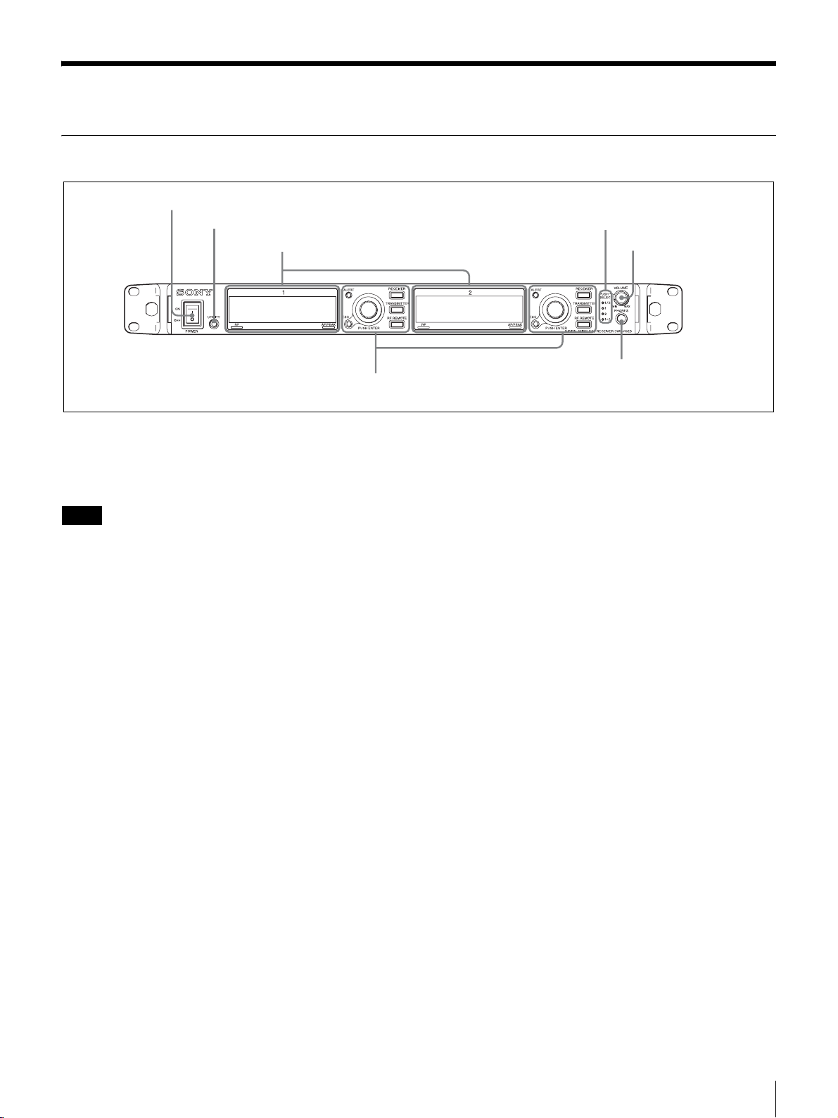
Front Panel
1 POWER switch
2 UTILITY button
1 Display (see page 12)
2 Controls (see page 13)
a POWER switch
Turns the receiver on or off.
Set to the \ position to turn the receiver on. Set to the a
position when turning off the main power supply.
Note
When DC power is being input, you cannot turn off the
power supply using this switch. To turn off the power
supply in such cases, turn off the connected external power
supply, or disconnect the connected cable.
3 Monitor indicators
d VOLUME control
5 PHONES terminal
b UTILITY (UTILITY menu) button
Press to display UTILITY menu. This button lights up
brightly during UTILITY menu operation.
c Monitor indicators
One of four indicators lights up corresponding to the
VOLUME control operation.
1/2: Audio from channel 1 is output from the L channel of
the headphones and audio from channel 2 is output from
the R channel.
1: Audio from channel 1 is output from the L and R
channels of the headphones.
2: Audio from channel 2 is output from the L and R
channels of the headphones.
1+2: Audio from channel 1 and 2 are mixed to be output L
and R channels of the headphones.
d VOLUME (monitor channel selection/monitor
volume) control
Press to change the audio output from the headphones.
Rotate to control monitor volume.
e PHONES (headphones) terminal
Connect the headphones here.
Parts Identification
11
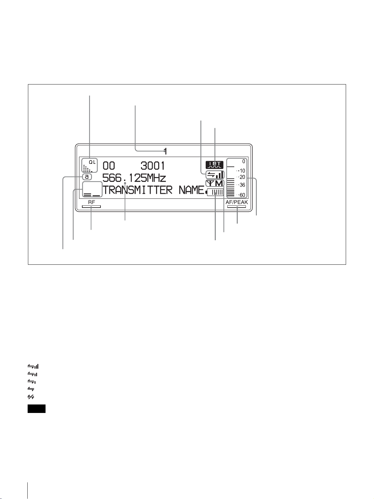
1 Display
The contents of the display before the DWR-R02D enters menu operation (top display) are described below. Since the top
display shows information contained in the metadata sent from the transmitter as well as the receiver settings and status,
this can be used for operation monitoring.
The display contents of receiver channel 1 and 2 are the same. The display of receiver channel 1 is used for illustration
purposes.
1 QL meter
2 Receiver channel number
3 Cross Remote condition indication
4 Digital output sync indication
9 Reception channel information
0 RF indicator
qa RF level meters
qs Antenna selection indication
a QL (signal quality level) meter
Indicates the quality of data that is received.
This meter allows you to monitor RF signal deterioration
that may occur when there is signal interference or when
the transmitter is too far from the receiver.
b Receiver channel number
Indicates the receiver channel number.
c Cross Remote condition indication
Indicates the signal transmission condition of the wireless
remote control function (four levels).
: Good transmission
: Somewhat good transmission
: Somewhat poor transmission
: Poor transmission
: Unable to communicate with paired transmitter
Note
When the wireless remote control function (see page 30) is
off, this indication does not appear.
d Digital output sync indication
Indicates sync status of the signal output from the
DIGITAL OUT connectors.
5 Audio level meter
6 AF/PEAK indicator
7 Transmission power indication
8 Battery indication
INT: Output signal is in sync with the internal clock.
EXT: Output signal is in sync with the signal input from
the WORD SYNC IN connector.
e Audio level meter
Indicates the level of audio signal input to the transmitter.
The segments indicating below the reference input level of
the transmitter appear dimly.
When “MIC” is set for the reference input level on the
transmitter: Segments indicating –36 dBFs or below
appear dimly.
When “LINE” is set for the reference input level on the
transmitter: Segments indicating –20 dBFs or below
appear dimly.
f AF/PEAK (audio signal peak) indicator
Lights up green when the audio signal exceeding reference
level is input to the transmitter.
Lights up red when the audio signal exceeding –3 dBFs is
input to the A/D converter on the transmitter.
g Transmission power indication
Indicates the current transmission power setting. This
setting can be changed in the TRANSMITTER menu (see
page 29).
12
Parts Identification
H: transmitting at 50 mW
M: transmitting at 10 mW
L: transmitting at 1 mW
2 Controls
The control areas for channel 1 and channel 2 are identical.
For details on changing the transmitter settings, see
“Changing the Settings on the Transmitter” on page 35.
h Battery indication
Based on metadata from the transmitter, this shows the
transmitter’s battery condition according to eight level
indications.
Replace both batteries when the battery indication starts to
flash.
For details on how to change the batteries on the
transmitter, refer to the Operating Instructions supplied
with the transmitter.
i Reception channel information
Shows the information on receiving signal and the
transmitter name.
First row: Group and channel
Middle row: Frequency of the channel
Last row: Transmitter name and sleep state
j RF (radio reception) indicator
Lights up to indicate the level of the signal input from the
ANTENNA a/b IN connector as follows.
On in orange: 80 dBµ or more
On in green: 25 dBµ to 80 dBµ
On in red: 15 dBµ to 25 dBµ
Off: Less than 15 dBµ
k RF (radio reception) level meters
Indicates the level of the signal input from the ANTENNA
a/b IN connector. The number of segments that light up
depends on the input level.
l Antenna selection indication
Indicates the antenna currently selected by the diversity
function.
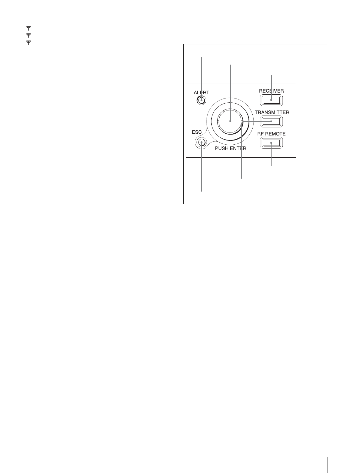
1 ALERT indicator
2 Jog dial
3 RECEIVER menu
button
4 RF REMOTE menu
button
5 TRANSMITTER menu button
6 ESC button
a ALERT (alert) indicator
Lights up red when error is detected.
For the specific causes of alerts and remedies, see “When
the Alert Indicator Lights” on page 37.
b Jog dial
Rotate to select an item or a parameter value in the menu.
Press to enter the selected item or parameter value.
c RECEIVER (RECEIVER menu) button
Press to enter the RECEIVER menu. While in the
RECEIVER menu, this button lights up brightly.
d RF REMOTE (RF REMOTE menu) button
Press to enter the RF REMOTE menu. While in the RF
REMOTE menu, this button lights up brightly.
e TRANSMITTER (TRANSMITTER menu) button
Press to enter the TRANSMITTER menu. While in the
TRANSMITTER menu, this button lights up brightly.
f ESC (escape) button
Press to go back to the previous menu display.
Parts Identification
13
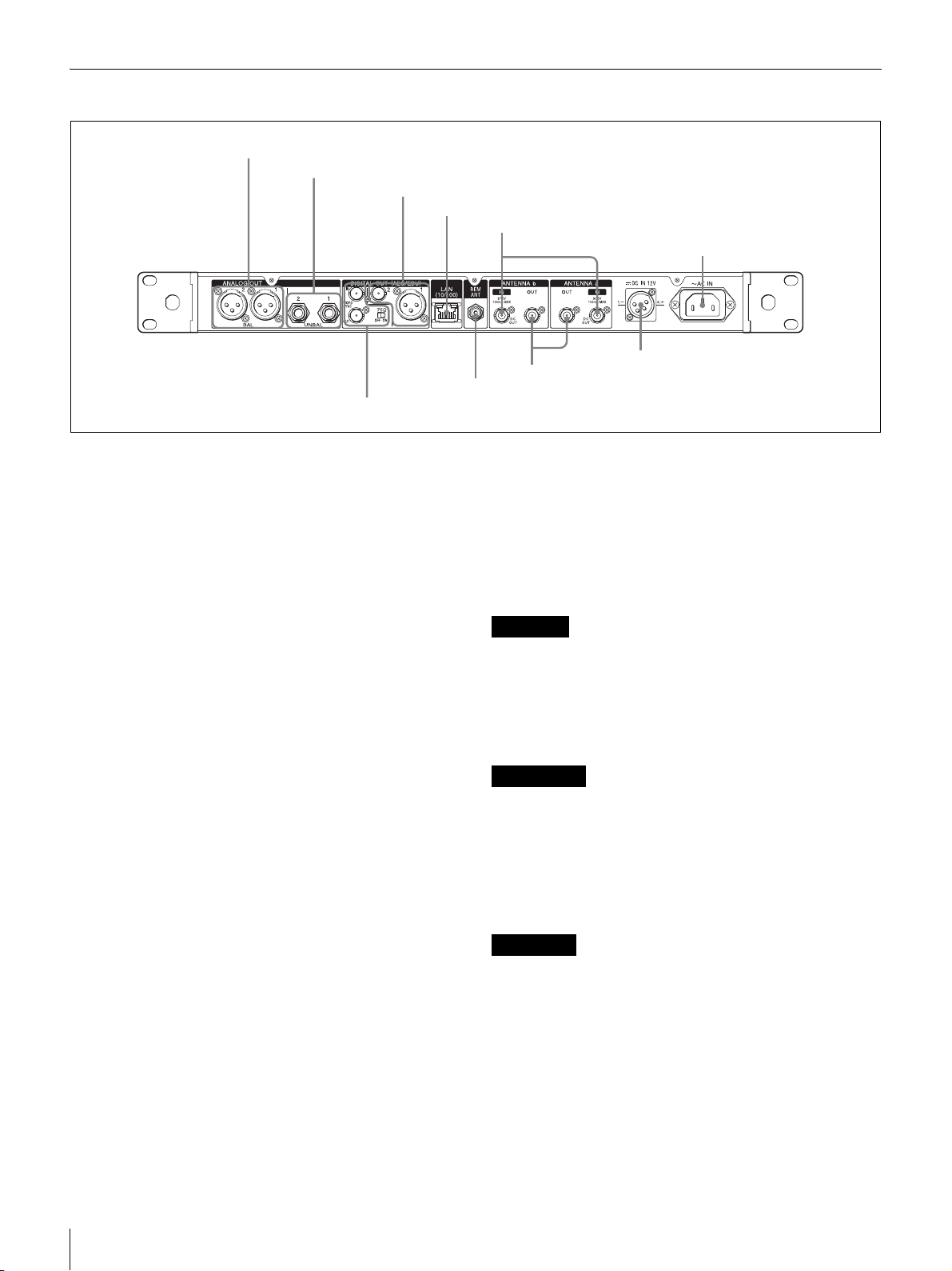
Rear Panel
1 ANALOG BALANCED OUT 1/2 connectors
2 ANALOG UNBALANCED OUT 1/2 connectors
3 DIGITAL OUT 1/2 connectors
4 LAN (10/100) connector
5 ANTENNA a/b IN connectors
6 AC IN connector
q; WORD SYNC IN/OUT connectors and 75 Ω termination switch
a ANALOG BALANCED OUT (analog balanced
output) 1/2 connectors (XLR type)
Connect the analog input connector of mixer, amplifier, or
other equipment.
You can use menu operations to set the output level and to
disconnect the XLR connector grounding (pin 1) and the
chassis grounding.
For details, see “Setting Analog Audio Output Level (BAL
OUT LEVEL)” on page 29 and “Ground Lift Function
(GROUND LIFT)” on page 29.
b ANALOG UNBALANCED OUT (analog
unbalanced output) 1/2 connectors (TS phone type)
These connectors output the same audio signals as the
ANALOG BALANCED OUT connectors.
Connect these to the TS PHONE input connectors of guitar
effects units and amplifiers, for example.
You can use menu operations to insert attenuators into the
audio output.
For details, see “Setting the Attenuator for the Analog
Unbalanced Output (UNBAL OUT ATT)” on page 29.
c DIGITAL OUT (digital output) 1/2 connectors
(1: XLR type, 2: BNC-R)
These connectors output a digital audio signal in AES3
format. Connect the digital input connector of mixer,
amplifier, or other equipment.
d LAN (Ethernet) (10/100) connector (RJ-45)
This is a 100Base-TX connector for network connection.
Connect to a Windows PC, in order to use the supplied
Wireless Studio software for communications with the
computer.
For connection to a computer, use a category 5 or superior
LAN cable with a maximum length of 100 m (approx.
8 ANTENNA a/b OUT connectors
7 DC IN connector
9 REM ANT
330 ft). If the connection requires a total cable length
exceeding 100 m (approx. 330 ft), use a hub between the
computer and the DWR-R02D.
Use the following type of cable when:
Directly connecting the computer and the DWR-R02D:
Cross cable
Using a hub between the computer and the DWRR02D: Straight cable
CAUTION
• Do not touch the LAN connector directly with your
hands. The transfer of static electricity may result in
malfunction of the unit.
• For safety, do not connect the connector for peripheral
device wiring that might have excessive voltage to this
port. Follow the instructions for this port.
ATTENTION
• Ne touchez pas le connecteur LAN directement avec vos
mains. Le transfert d’électricité statique peut entraîner
un dysfonctionnement de l’appareil.
• Par mesure de sécurité, ne raccordez pas le connecteur
pour le câblage de périphériques pouvant avoir une
tension excessive à ce port. Suivez les instructions pour
ce port.
VORSICHT
• Berühren Sie den LAN-Anschluss nicht direkt mit den
Händen. Durch elektrostatische Entladungen können
Fehlfunktionen des Geräts verursacht werden.
• Aus Sicherheitsgründen nicht mit einem
Peripheriegerät-Anschluss verbinden, der zu starke
Spannung für diese Buchse haben könnte. Folgen Sie
den Anweisungen für diese Buchse.
14
Parts Identification
 Loading...