

Page 1
DVD Recorder
3-855-576-15(1)
Instructions For Use
DVO-1000MD
© 2005 Sony Corporation
Page 2
Owner's Record
The model and serial numbers are located at the rear.
Record these numbers in the space provided below.
Refer to these numbers whenever you call upon your
Sony dealer regarding this product.
Model No. ____________________
Serial No. ____________________
WARNING
To reduce the risk of fire or electric shock, do
not expose this apparatus to rain or moisture.
3. The leakage current could increase when connected
to other equipment.
4. This equipment generates, uses, and can radiate radio
frequency energy. If it is not installed and used in
accordance with the instruction manual, it may cause
interference to other equipment. If this unit causes
interference (which can be determined by
unplugging the power cord from the unit), try these
measures: Relocate the unit with respect to the
susceptible equipment. Plug this unit and the
susceptible equipment into different branch circuit.
Consult your dealer. (According to standard
EN60601-1-2 and CISPR11, Class B, Group 1)
To avoid electrical shock, do not open the
cabinet. Refer servicing to qualified personnel
only.
THIS APPARATUS MUST BE EARTHED.
Symbols on the products
This symbol indicates the equipotential
terminal which brings the various parts of a
system to the same potential.
This symbol is intended to alert the user to
the presence of important operating and
maintenance (servicing) instructions in the
literature accompanying the appliance.
Important safeguards/notices for use in
the medical environments
1. All the equipments connected to this unit shall be
certified according to Standard IEC60601-1,
IEC60950, IEC60065 or other IEC/ISO Standards
applicable to the equipments.
2. When this unit is used together with other equipment
in the patient area*, the equipment shall be either
powered by an isolation transformer or connected via
an additional protective earth terminal to system
ground unless it is certified according to Standard
IEC60601-1.
* Patient Area
Caution
When you dispose of the unit or accessories, you must
obey the law in the relative area or country and the
regulation in the relative hospital.
WARNING on power connection
Use a proper power cord for your local power supply.
1. Use the approved Power Cord (3-core mains lead) /
Appliance Connector / Plug with earthing-contacts
that conforms to the safety regulations of each
country if applicable.
2. Use the Power Cord (3-core main lead) / Appliance
Connector / Plug conforming to the proper ratings
(Voltage, Ampere).
If you have questions on the use of the above Power
Cord / Appliance Connector / Plug, please consult a
qualified service personnel.
WARNING on power connection for
medical use
Please use the following power supply cord.
With connectors (plug or female) and cord types other
than those indicated in this table, use the power supply
cord that is approved for use in your area.
United States Canada
Plug Type HOSPITAL GRADE* HOSPITAL GRADE*
Female end E62405, E35708 LR53182, LL022442,
Cord type E159216, E35496
Minimum cord set
rating
Safety approval UL Listed CSA
*Note: Grounding reliability can only be achieved when the equipment is connected to an equivalent receptacle marked ‘Hospital Only’
or ‘Hospital Grade’.
Min.Type SJT
Min.18 AWG
10A/125V 10A/125V
LL088408
LL112007-1, LL20262,
LL32121, LL84494
Min.Type SJT
Min.18AWG
R1.5m
When installing the installation space must be secured in
consideration of the ventilation and service operation.
• Do not block the ventilation slots at the rear, and vents
of fans.
• Leave a space around the unit for ventilation.
• Leave more than 10 cm of space in the rear of the unit
to secure the operation area.
2
Page 3

Caution
Use of controls or adjustments or performance of
procedures other than those specified herein may result
in hazardous radiation exposure.
This DVD RECORDER is classified as a CLASS 1
LASER PRODUCT.
Caution
The use of optical instruments with this product will
increase eye hazard.
Caution
The apparatus shall not be exposed to dripping or
splashing and no objects filled with liquid, such as vases,
shall be placed on the apparatus.
Important
The nameplate is located on the bottom.
You are cautioned that any changes or modifications not
expressly approved in this manual could void your
authority to operate this equipment.
All interface cables used to connect peripherals must be
shielded in order to comply with the limits for a digital
device pursuant to Subpart B of Part 15 of FCC Rules.
If you have any questions about this product, you may
call;
Sony Customer Information Service Center 1-800-2227669 or http://www.sony.com/
Declaration of Conformity
Trade Name: SONY
Model: DVO-1000MD
Responsible Party: Sony Electronics Inc.
Address: 16530 Via Esprillo, San
Diego, CA 92127 U.S.A.
Telephone Number: 858-942-2230
This device complies with part 15 of the FCC Rules.
Operation is subject to the following two conditions:
(1) this device may not cause harmful interference,
and (2) this device must accept any interference
received, including interference that may cause
undesired operation.
For the customers in the U.S.A.
This equipment has been tested and found to comply
with the limits for a Class B digital device, pursuant to
Part 15 of the FCC Rules. These limits are designed to
provide reasonable protection against harmful
interference in a residential installation. This equipment
generates, uses, and can radiate radio frequency energy
and, if not installed and used in accordance with the
instructions, may cause harmful interference to radio
communications. However, there is no guarantee that
interference will not occur in a particular installation. If
this equipment does cause harmful interference to radio
or television reception, which can be determined by
turning the equipment off and on, the user is encouraged
to try to correct the interference by one or more of the
following measures:
– Reorient or relocate the receiving antenna.
– Increase the separation between the equipment and
receiver.
– Connect the equipment into an outlet on a circuit
different from that to which the receiver is connected.
– Consult the dealer or an experienced radio/TV
technician for help.
For the customers in Canada
This unit has been certified according to Standard CSA
C22.2 NO.60601.1.
3
Page 4

Table of Contents
Precautions ............................................................. 5
Copyrights .............................................................. 6
Overview
Features .................................................................. 7
Location and Function of Parts ............................ 8
Front Panel ......................................................... 8
Rear Panel ........................................................ 11
Connection ........................................................... 13
Connecting External Equipment (1) ................ 13
Connecting External Equipment (2) ................ 14
Turning the Power On/Off .................................. 15
Setup Preparation ............................................... 16
Selecting Either NTSC or PAL Video Signal
System ............................................................ 16
Setting the Date and Time ................................ 18
Selecting the Remote Interface ........................ 20
Recording
Handling Discs ..................................................... 22
Usable Discs ..................................................... 22
Notes on Handling ........................................... 22
Loading and Unloading Discs .......................... 22
Preparations for Recording ................................ 24
Selecting Input Signals ..................................... 24
Selecting the Recording Mode ......................... 25
Recording ............................................................. 26
Recording Titles ............................................... 26
Marking Indexes During Recording ................. 27
Using a Foot Switch ......................................... 28
Adding Information to Titles ............................ 29
Pre Rec Function .............................................. 29
When the Disc Becomes Full During Recording .
30
Finalizing a Disc .................................................. 32
Formatting a Disc ................................................ 33
Playback
Playback ............................................................... 34
Usable Discs ..................................................... 34
Playback a Disc ................................................ 34
Fast Forward or Reverse Playback ................... 34
Adding Indexes During Playback .................... 34
Searching for Desired Point ................................ 35
Jumping to a Desired Title ............................... 35
Jumping to a Desired Chapter .......................... 35
Repeat Playback .................................................. 36
Repeat Playback Between Two Points (A-B
Repeat) ............................................................36
Repeat Playback of a Chapter ...........................38
Repeat Playback of a Title ................................38
Playing From the TITLE LIST Display ............39
Verifying Information on a Disc .........................40
Viewing Frozen Pictures ......................................41
Editing
Editing Titles ........................................................42
Verifying/Editing Information About the Title .42
Protecting a Title ...............................................43
Erasing a Title ...................................................44
Menu
Menu Configuration and the Menu List ............46
Menu Configuration ..........................................46
Menu List ..........................................................46
Basic Menu Operations .......................................50
Miscellaneous
Messages ...............................................................52
Error Messages .................................................52
Alarm Messages ...............................................52
Troubleshooting ....................................................55
Specifications ........................................................56
General ..............................................................56
Input/Output Connectors ..................................56
Control Signals .................................................56
Others ................................................................57
Using an SVRM-100A Remote Control Unit (Not
Supplied) ...............................................................57
Location and Function of Parts .........................57
Marking Indexes ...............................................58
Searching for a Particular Image - Index Scanning
58
Cuing a Particular Image by Specifying an Index
Number - Index Search ...................................58
Erasing an Index ...............................................58
Glossary ................................................................60
Index ......................................................................61
4
Table of Contents
Page 5

On the panel display: HUMID!
Precautions
On safety
• Should any liquid or solid object fall into the cabinet,
unplug the unit and have it checked by qualified
personnel before operating it further.
• Unplug the unit from the wall outlet if it is not to be
used for an extended period of time.
• To disconnect the cord, pull it out by the plug. Never
pull the cord itself.
On operation and storage location
Avoid operation or storage in any of the following
places.
• Location subject to extremes of temperature
(operating temperature range 5°C to 40°C (41°F to
104°F))
• Location subject to direct sunlight for long periods, or
close to heating appliances.
• Damp or dusty places
• Location subject to severe vibrations
• Location near equipment generating electromagnetic
emissions
• Location near transmitting stations generating strong
radio waves
• Location exposed to dripping or splashing. Do not put
objects filled with liquid, such as vases, on the unit.
Splashing the unit with liquid may cause a
malfunction.
When the disc is being loaded in the unit
If you give a violent shock to the unit or move it with a
disc loaded because the unit is recording or playing
back, the disc may be damaged. Be sure to remove a disc
before moving the unit.
On cleaning
If the casing or panel is dirty, wipe it gently with a soft
dry cloth. In the event of extreme dirt, use a cloth
steeped in a neutral detergent to remove the dirt, then
wipe with a dry cloth. Applying alcohol, thinner,
insecticides, or other volatile solvents may result in
deforming the casing or damaging the finish.
On repacking and shipping
Save the original shipping carton and packing material;
they will come in handy if you ever have to ship your
unit. For maximum protection, repack your unit as it was
originally packed at the factory, and take care not to
impact violent shocks in transit.
Operate the unit in a horizontal position
This unit is designed to be operated in a horizontal
position. Do not operate it on its side, or tilted through
an excessive angel.
Avoid violent impacts
Dropping the unit, or otherwise imparting a violent
shock to it, is likely to cause it to malfunction.
Do not obstruct ventilation openings
To prevent the unit from overheating, do not obstruct
ventilating openings, by for example wrapping the unit
in a cloth while it is in operation.
Condensation
If you move the unit from a very cold place to a warm
place, or use it in a damp location, condensation may
form on the optical pickup. Then, if the unit is operated
in this state, the unit does not record or play correctly.
When the power is turned on, the following message
appears, wait until it disappears before loading a disc.
On the monitor window: MOISTURE HAS BEEN
DETECTED.
Precautions
5
Page 6

Copyrights
• Materials played or recorded on this unit may be
copyrighted. Unauthorized recording of such material
may be contrary to the provisions of the copyright
laws. You cannot use those materials without
permission from the owners except for playing those
materials for personal use.
• This unit incorporates copyright protection
technology that is protected by U.S. patents and other
intellectual property rights. Use of this copyright
protection technology must be authorized by
Macrovision, and is intended for home and other
limited viewing uses only, unless otherwise authorized
by Marcrivision. Reverse engineering or disassembly
is prohibited.
• Since this unit has a copy guard function, software and
broadcasting programs that contain copy protection
signals cannot be recorded on this unit.
• Since this unit has a function for prohibiting playback
of not-permitted discs such as pirated discs, you
cannot play such discs using this unit.
Exemption from responsibility for
compensation for recorded data
We will not take any responsibility for compensation for
data that could not be recorded or played due to
problems such as malfunction of the unit, corruption or
loss of recorded or edited data, or any losses caused by
such malfunctions or loss of data.
Please be aware of this policy beforehand.
Problems may occur if you perform the following
operations:
• When you use a disc recorded or edited using the unit
with another DVD recorder or the DVD drive of a
personal computer.
• When you attempt to re-use a disc with this unit, after
using it in the operations described above.
• When you use a disc recorded using another DVD
recorder or DVD drive of a personal computer with
this unit.
6
Copyrights
Page 7

Overview
• Title list
You can display the list of titles recorded on the disc,
and using this list, you can search for the desired title
from which you can start playback on the list.
Features
The DVO-1000MD is a DVD Recorder designed for use
with video equipment such as external equipment. The
DVO-1000MD compresses video signals sent from the
external equipment with an MPEG-2 format and audio
signals with Dolby Digital format (2CH), and records
video and audio signals on a DVD+RW disc.
The following are the principal features of the unit.
Rewritable DVD+RW
recording media
Since rewritable DVD+RW disc is used as a removable
disc, the disc is automatically finalized and discs
recorded with this unit can be played on other DVD+RW
players. Also, the unit searches for the first blank space
automatically and starts recording from that point. Thus,
it is not necessary to cue up and you can start recording
right after you insert the disc.
1) is a trademark.
High-quality and long recording
The unit employs VBR (Variable Bit Rate) recording
which varies the compressed rate of MPEG2
dynamically according to the images recorded, thereby
high-quality recording relative to recording time can be
realized. Also, you can select picture quality from
among three recording modes: HQ (about 60 minutes:
CBR (Constant Bit Rate)), SP (about 120 minutes:
VBR) and LP (about 180 minutes: VBR).
Recording indexes
You can mark indexes during recording or playback.
This allows you to search for the desired points instantly
during playback, and also to play a segment specified by
two points repeatedly.
High-quality audio recording
The Dolby Digital 1) recording format allows you to
record high-quality audio sound simultaneously with the
video signals.
1) The unit is manufactured under license from Dolby Laboratories.
“Dolby” and Double-D symbol are trademarks of Dolby Laboratories.
1)
disc as the
Variety of input/output interfaces
Digital interfaces
This unit is equipped with an i.LINK
DV format digital video and audio signals can be input.
1) i.LINK and are trademarks of Sony Corporation and indicate that
this product is in agreement with IEEE1394-1995 specifications and
their revisions.
Analog interfaces
This unit can also use the following analog interfaces.
• Analog video
– Composite inputs (with loop-through)/output
– S-video inputs (with loop-through)/output
• Analog audio
– 2-channel inputs/outputs
– Monitor output
1)
connector so that
Control interfaces
This unit is equipped with the following interfaces.
• RS-232C interface/USB interface
This unit is equipped with 9-pin RS-232C which is
compatible with the SVO-9500MD video cassette
recorder protocol and a USB interface which is
compatible with the RS-232C protocol. These
interfaces provide the following new functions in
addition to existing remote control functions of the
unit:
– Meta data input/output per title
You can record meta data such as name, ID,
production date from external equipment for each
title.
– Input/output of updated data in real time
• i.LINK interface
Follows AV/C protocol
You can select one from among an RS-232C interface,
a USB interface, or an i.LINK interface from a menu.
• Control using the remote control unit
You can use the following remote control units.
– SVRM-100A remote control unit (not supplied)
Compact size
The compact size of the unit makes the unit suitable for
use with medical instruments which are designed for use
in limited spaces.
Overview
Playback using the quick search function
• Jumping to desired titles
• Jumping to the desired indexes
This allows you to search by indexes.
Features
7
Page 8
Location and Function of Parts
Overview
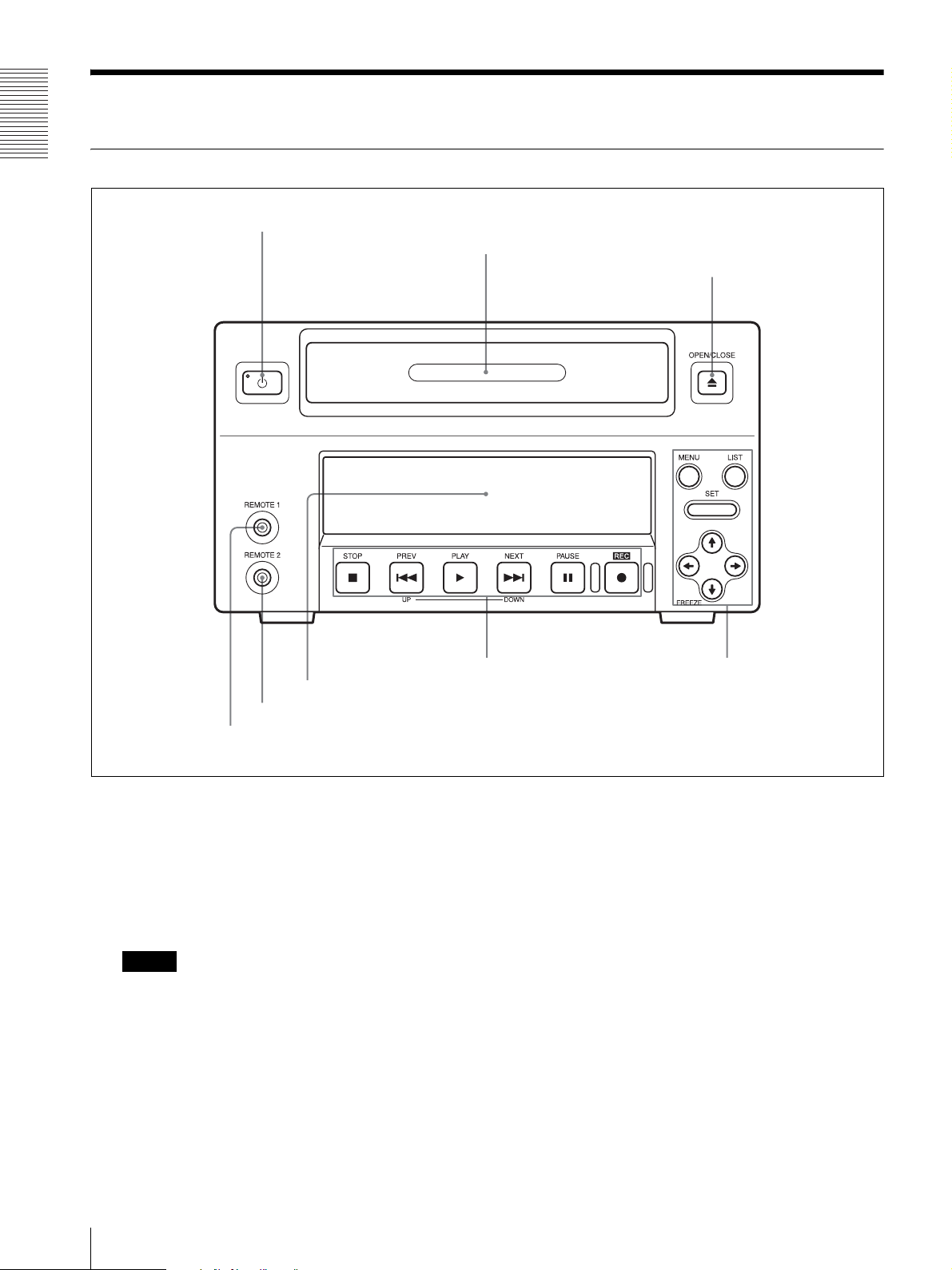
Front Panel
1 1 (Power) switch and standby indicator
2 Disc tray
3 OPEN/CLOSE button
6 Front panel display
5 REMOTE 2 connector
4 REMOTE 1 connector
1 1 (power) switch and standby indicator
Press to power on the unit when the MAIN POWER
switch (see page 11) on the rear panel is turned on.
This causes the front panel display to light. Even if
this switch is set to off, the indicator is lit in green
when the MAIN POWER switch is set to on. To
power off the unit, press this switch again.
Note
If the MAIN POWER switch on the rear panel is
not set to on, the power is not on even if you press
the 1 (power) switch.
2 Disc tray
Used to insert or remove the disc.
3 OPEN/CLOSE button
Press to open or close the disc tray.
8 Menu/disc control section7 Disc control section
4 REMOTE 1 connector (stereo mini jack)
Connect a SVRM-100A remote control unit (not
supplied) to this connector for remote control.
5 REMOTE 2 connector (mini jack)
Connect a foot switch (not supplied) to this
connector. You can control recording and pausing
using this foot switch.
8
Location and Function of Parts
Page 9
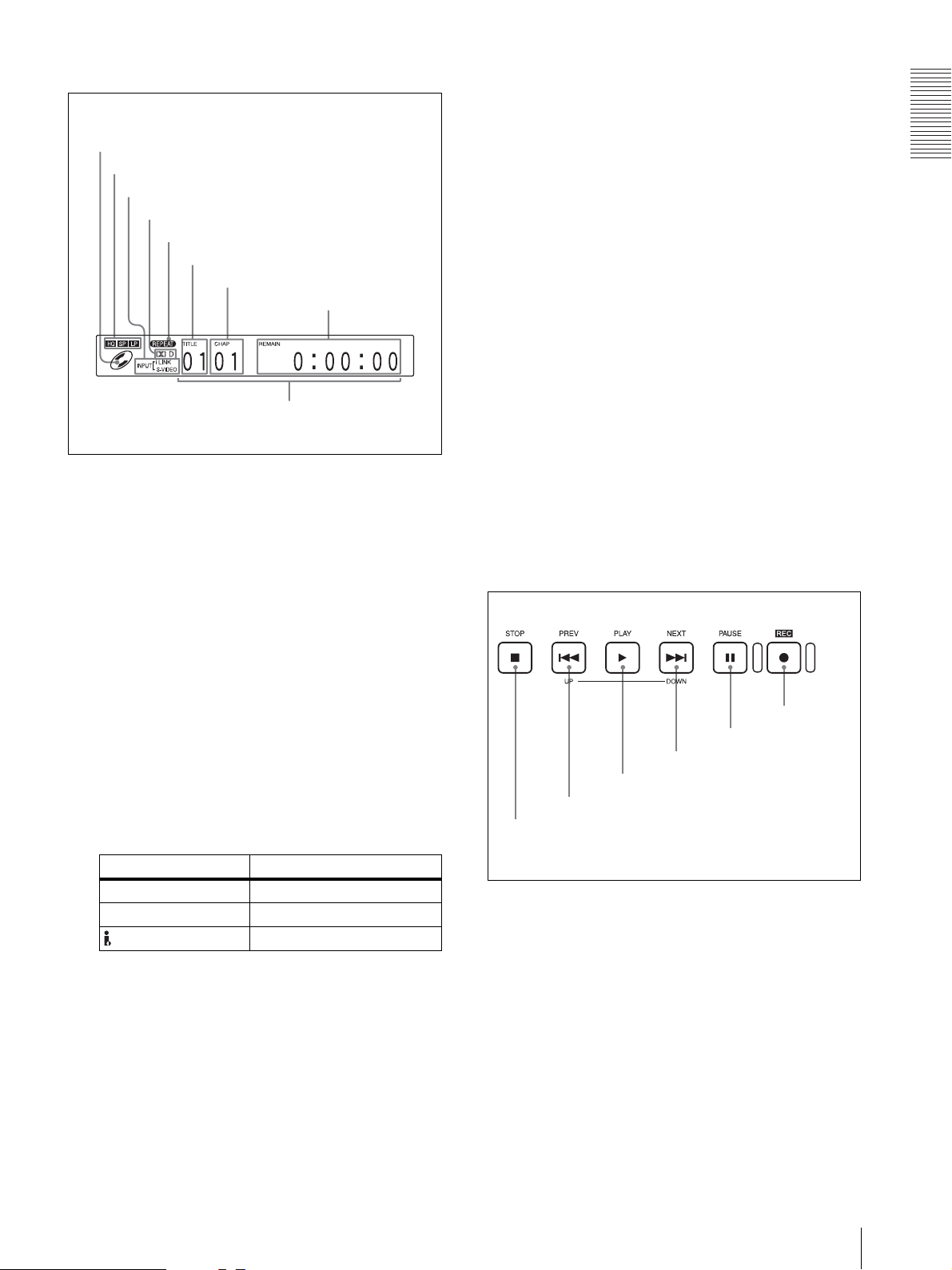
6 Front panel display
F TITLE indicator
Indicates the number of the title which is being
recorded or played back.
A Disc indicator
B Recording mode indicator
C INPUT signal indicator
D Dolby indicator
E REPEAT indicator
F TITLE indicator
G CHAP indicator
H Time indicator
I Main display section
A Disc indicator
Lights when a DVD+RW disc which can be
recorded and played back with this unit is loaded in
the tray. This indicator goes off when a disc tray
opens.
This indicator does not light when the disc which
cannot be used with this unit is loaded in the tray.
G CHAP (chapter) indicator
Indicates the number of the chapter which is being
recorded or played back.
H Time indicator
In normal operation, the elapsed time is displayed.
While recording, the elapsed time or the remaining
time of the disc is displayed according to the menu
setting of REC COUNTER (see page 49) of the
SETUP MENU. When the remaining time of the
disc is selected, “REMAIN” is lit.
I Main display section
During menu operation or list operation, the
selected item is displayed.
If an abnormal operation occurs, an error code or
alarm message is displayed.
In this manual, menu operation is explained using
the monitor display. On the main display section of
the front panel display, the menu item currently
selected on the monitor display is lit.
7 Disc control section
Overview
B Recording mode indicator
Indicates the recording mode.
While a disc is being played back, the recording
mode in which the disc was recorded is indicated.
When recording, the selected recording mode is
indicated. When a disc which has been recorded
using another DVD recorder is played, none of the
indicators light.
C INPUT signal indicator
Indicates the input signal currently selected.
Input connector Indicator
S-VIDEO IN S-VIDEO
VIDEO IN VIDEO
DV IN (i.LINK) i.LINK
D Dolby indicator
Goes out when an audio signal recorded in a format
other than in the Dolby Digital format is played
back.
E REPEAT indicator
Lights during repeat playback.
For detailed information on repeated playback, see
“Repeat Playback” on page 36.
F zREC button
E XPAU S E b u tt o n
D >NEXT/DOWN button
C BPLAY button
B .PREV/UP button
A xSTOP button
A xSTOP button
Press this button to stop the recording or playback
operation.
B .PREV/UP button
PREV: Used to jump to a chapter.
When pressed once, moves to the start point of the
chapter currently being played back.
When pressed twice, moves to the start point of the
previous chapter.
Pressing this button with the BPLAY button held
down allows you to view fast reverse playback at a
speed three times the speed of the normal playback.
Location and Function of Parts
9
Page 10
Overview
UP: Used to go back to the previous page during
title operation in the TITLE LIST display.
C BPLAY button
When you press this button, it lights and playback
begins.
Press this button to display the menu on the monitor
screen and the front panel display. Press it again to
exit the menu display.
B LIST button
Press this button to display the TITLE LIST menu.
D >NEXT/DOWN button
NEXT: Used to jump to a chapter.
When pressed once, moves to the start point of the
next chapter.
Pressing this button with the BPLAY button held
down allows you to view fast forward playback at a
speed three times the speed of the normal playback.
DOWN: Used to go to the next page during title
operation in the TITLE LIST display.
E XPAUSE button
During playback, press this button to pause the
playback operation. While paused, a still picture is
displayed.
Pressing this button again or pressing the BPLAY
button allows you to restart the playback operation.
During recording, press this button to pause the
recording operation. Pressing this button again
allows you to restart the recording operation.
Note
During recording, each time you press the
XPAUSE button, indexes are automatically
marked.
F zREC button
When you press this button, this button lights and
recording begins.
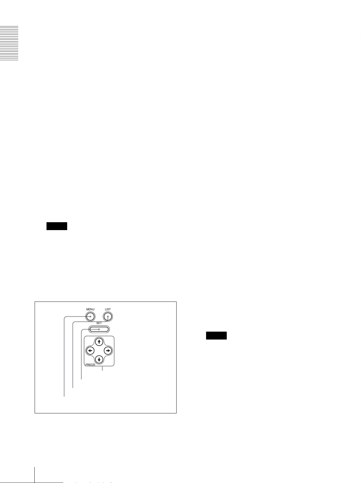
8 Menu/disc control section
C SET button
Press this button to save new settings, such as
selected menu items.
D V, v, B, b (cursor operation) buttons
Used to perform menu operation. Press these
buttons to select a menu item, to change numeric
values, and so on.
B and b buttons are also used to jump to the proper
point during playback operations.
B button: When pressed once during playback,
jumps to the start point of the title currently being
played back. When pressed twice, jumps to the start
point of the previous title. When pressed with the
SET button during stopping, jumps to the beginning
of the first title in the disc.
b button: When pressed once during playback,
jumps to the start point of the next title. When
pressed with the SET button during stopping, jumps
to the beginning of the last chapter in the disc.
For detailed information on titles, see page 26. For
detailed information on chapters, see page 28.
v (FREEZE) button: When pressed the first time
during playback, the picture becomes a frame
frozen picture. When pressed the second time, the
frame frozen picture is replaced with the frozen first
field picture. When pressed the third time, the first
field frozen picture is replaced with the second field
frozen picture. Whenever you press the v button,
the frozen picture is replaced in this sequence.
The FREEZE MODE item (see page 48) of the
SETUP MENU allows you to decide whether the
first frozen picture is a frame frozen or field frozen
picture.
A MENU button
A MENU button
Used to enable the menu operation.
10
Location and Function of Parts
Note
The v button does not function as a FREEZE
button when the menu window or the TITLE LIST
window is displayed. In those windows, thie button
functions only as a cursor operation button.
D V, v, B, b buttons
C SET button
B LIST button
Page 11
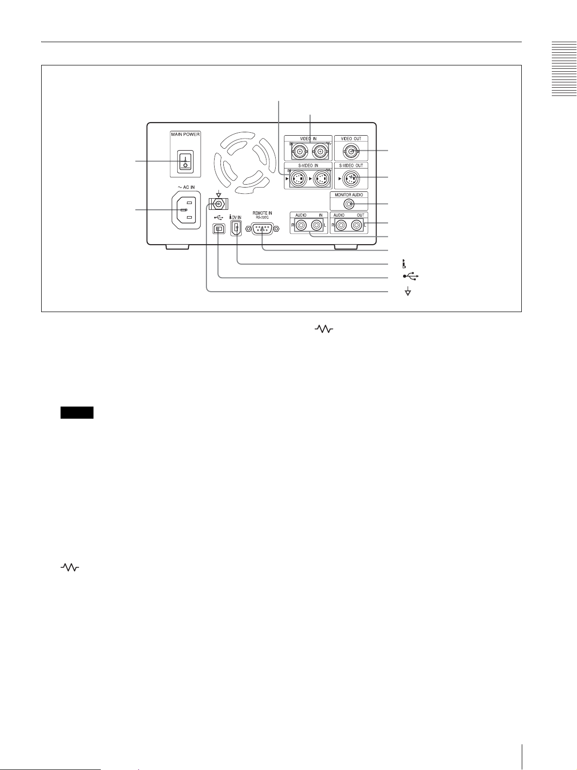
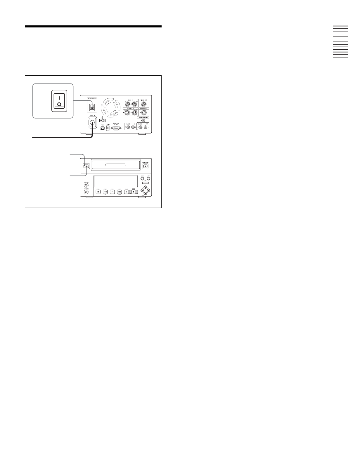
Rear Panel
1 MAIN POWER switch
qd -AC IN connector
1 MAIN POWER switch
Switch to the = side to turn the power on. Switch to
the z side to turn the power off. Normally you
should leave this switch in the on position and
power the unit on and off with the power switch on
the front panel.
Note
If you need to turn the main power off when not
using the unit for long periods and so on, always
power the unit off with the 1 (power) switch on the
front panel before setting this switch to off.
2 S-VIDEO IN connectors
3 VIDEO IN connectors
left connector are output from the right connector to
other equipment. When no connection is made to
the right connector, the left connector is terminated
automatically with an impedance of 75 Ω.
4 VIDEO OUT connector (BNC type)
This connector outputs analog composite video
signals.
5 S-VIDEO OUT connector (4-pin mini DIN)
This connector outputs the analog S video signals.
Overview
4 VIDEO OUT connector
5 S-VIDEO OUT connector
6 MONITOR AUDIO connector
7 AUDIO OUT L/R connectors
8 AUDIO IN L/R connectors
9 REMOTE IN RS-232C connector
0 DV IN (i.LINK) connector
qa USB connector
qs Equipotential ground terminal
connector
). Thus the same signals which are input to the
2 S-VIDEO IN connectors (4-pin mini DIN)
The left S-VIDEO IN connector inputs analog S
video signals.
The two connectors are loop-through connectors. If
you connect S video input signals to the left
connector, you can bridge-connect the signal to
other equipment via the right connector (marked
). Thus the same signals which are input to the
left connector are output from the right connector to
other equipment. When no connection is made to
the right connector, the left connector is terminated
automatically with an impedance of 75 Ω.
3 VIDEO IN connectors (BNC type)
The left VIDEO IN connector inputs analog
composite video signals.
The two connectors are loop-through connectors. If
you connect composite video signals to the left
connector, you can bridge-connect the signal to
other equipment via the right connector (marked
6 MONITOR AUDIO connector (phono jack)
This connector outputs monaural audio signals for
monitoring.
The audio signals to be output from this connector
can be selected among from audio channel 1, audio
channel 2, or mixed audio signals, using AUDIO
MON CH (see page 47) of the SETUP MENU.
7 AUDIO OUT L/R connectors (phono jack)
These connectors output analog audio signals.
8 AUDIO IN L/R connectors (phono jack)
These connectors input analog audio signals.
9 REMOTE IN RS-232C connector (9-pin)
This is a 9-pin RS-232C interface which is
compatible with the SVO-9500MD video cassette
recorder protocol.
Location and Function of Parts
11
Page 12

Overview
Use this connector to control this unit by
connecting it to equipment such as an external
equipment which supports the RS-232C interface.
0 DV IN (i.LINK) connector (6-pin)
This connector inputs digital video signals
conforming to the i.LINK protocol.
Also, this connector is used to control this unit by
connecting it to equipment such as an external
equipment which supports i.LINK.
qa USB connector
This connector is used to control this unit by
connecting it to equipment such as an external
equipment which supports a USB interface.
This connector is USB 2.0 which supports Fullspeed USB (12Mbps).
qs Equipotential ground terminal connector
This connector is used to connect to the
equipotential plug to bring the various parts of the
system to the same potential.
See “Important safeguards/notices for use in the
medical environments” on page 2.
qd -AC IN connector
Use power cord suitable for your local power
supply (not supplied).
See “WARNING on power connection” and
“WARNING on power connection for medical use”
on page 2.
12
Location and Function of Parts
Page 13
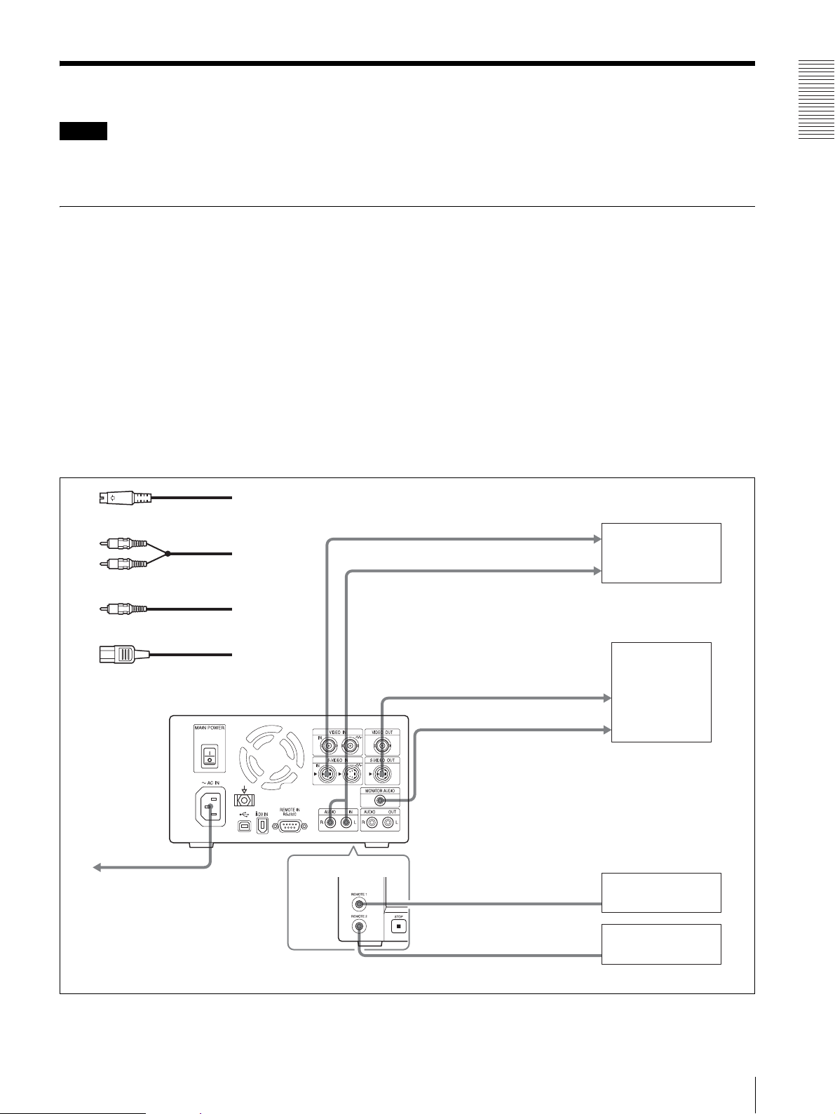
Connection
Notes
• Before making connections, be sure to turn the power
of any peripheral equipment off.
Connecting External Equipment (1)
This section gives a connection example to operate the
unit connected to external equipment using a remote
control unit (not supplied) and/or foot switch (not
supplied).
Settings required for using this connection
example
Make the following settings before operating in this
connection example using SETUP MENU.
For detailed information on menu operation, see “Basic
Menu Operations” on page 50.
• Audio output selection
Select the audio output channel using the AUDIO
MON CH sub menu of SETUP MENU (see page 47).
1
S-video cable (not supplied)
2
1
2
• Connect the AC power cord last.
Overview
– LCH: Outputs the audio signal of audio channel 1.
– RCH: Outputs the audio signal of audio channel 2.
– MIX: Outputs a mixed audio signal from both
channel 1 and channel 2. (factory setting)
• Input signal selection
Select the input signal “ANALOG” using the INPUT
SELECT sub menu of SETUP MENU (see page 24).
• Foot switch mode selection
Select the operation mode of the foot switch from
among LOW EDGE (factory setting), HIGH EDGE
and LOW ACTIVE (see page 28).
To S-video output connector
External equipment
To analog audio output connector
Audio cable (not supplied)
Audio cable (not supplied)
3
Audio cable (not supplied)
Audio cable (not supplied)
4
AC power cord (not supplied)
Rear panel
4
to AC outlet
- AC IN
S-VIDEO IN
Front panel
AUIDO IN L/R
S-VIDEO OUT
REMOTE 1
1
To S-video input connector
3
To analog audio input connector
MONITOR AUDIO
REMOTE 2
Video monitor
SVRM-100A remote
control unit
Foot switch
Connection
13
Page 14
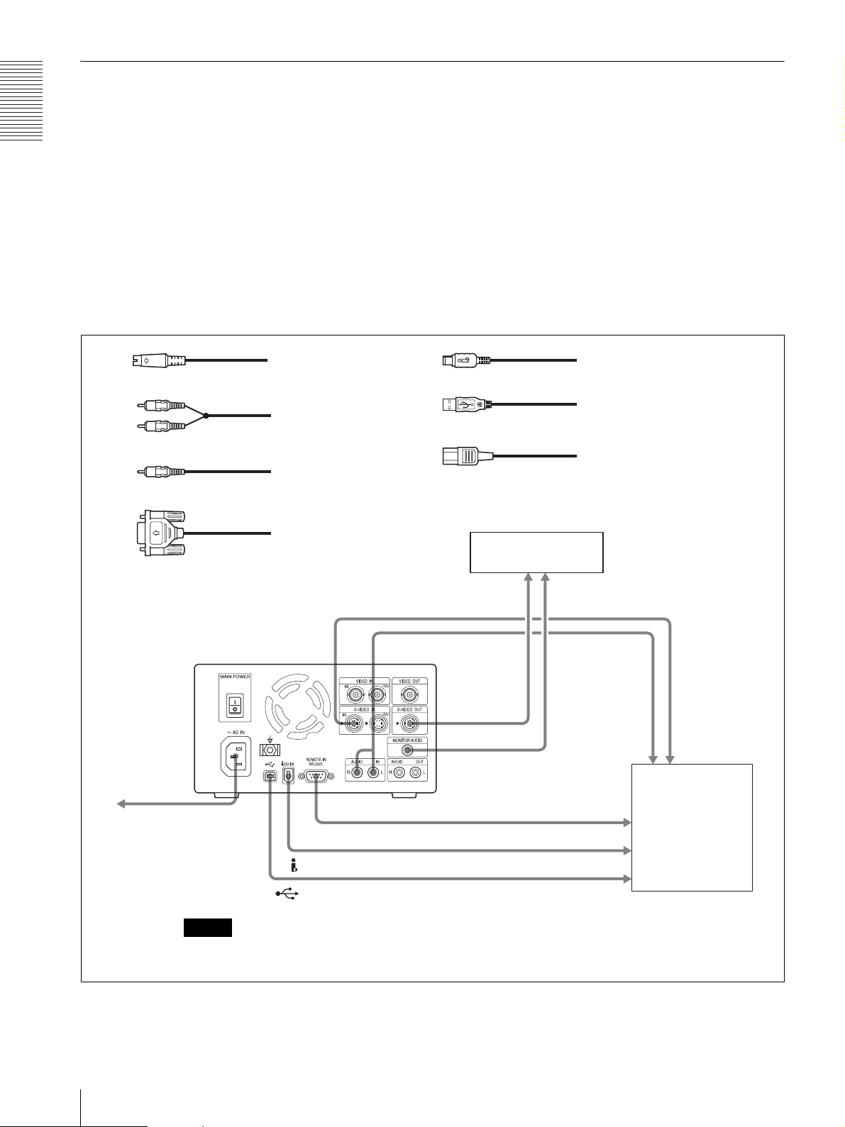
Connecting External Equipment (2)
Overview
This section gives an example to connect external
equipment for controlling the unit from connected
external equipment
Settings required for using this connection
example
Make the following settings before operating in this
connection example using SETUP MENU.
For detailed information on menu operation, see “Basic
Menu Operations” on page 50.
• Audio output selection
Select the audio output channel using the AUDIO
MON CH sub menu of SETUP MENU (see page 47).
– LCH: Outputs the audio signal of audio channel 1.
1
S-video cable (not supplied)
2
Audio cable (not supplied)
3
Audio cable (not supplied)
– RCH: Outputs the audio signal of audio channel 2.
– MIX: Outputs a mixed audio signal from both
channel 1 and channel 2. (factory setting)
• Input signal selection
Select the input signal “ANALOG” using the INPUT
SELECT sub menu of SETUP MENU (see page 24).
• Remote control mode selection
Select an interface to control the unit from among
RS232C (factory setting), USB and iLINK (see
page 20).
When controlling the unit, only one interface is
available from among RS232C (factory setting), USB
and iLINK.
5
DV cable (not supplied)
6
USB cable (not supplied)
7
AC power cable (not supplied)
4
RS-232C cable (cross type/not supplied)
7
to AC outlet
- AC IN
Note
You can use only one interface from among RS-232C, USB and
iLINK interfaces to control the unit remotely.
S-VIDEO IN
DV IN (i.LINK)
USB
To S-video input connector
AUDIO IN L/R
REMOTE IN RS-232C
Video monitor
1
1
S-VIDEO OUT
MONITOR AUDIO
4
to RS-232C connector
5
6
To analog audio input connector
2
3
To analog audio
output connector
to DV connector
to USB connector
To S-video
output connector
External equipment
14
Connection
Page 15
Turning the Power On/ Off
Turning the Power On
Rear panel
1
AC power cord (to AC outlet)
1
Push the 1 (power) switch on the front panel to put
the unit in the standby mode.
2
Set the MAIN POWER switch on the rear panel to
the z (off) side.
The standby indicator on the front panel goes off
and the power is turned off.
Overview
Standby indicator
Front panel
2
1
Connect the AC power cord (not supplied) to the
wall outlet, and then set the MAIN POWER switch
located on the rear panel to the [ (on) side.
The standby indicator on the front panel lights in
green.
2
Push the 1 (power) switch on the front panel.
The power of the unit is turned on and the front
panel display lights. The message “Welcome”
appears on the front panel display. Then, the
message changes to “Now loading...” When the
message changes finally to “NO DISC!,” you can
start the next operation.
When a disc is loaded in the unit, “0101 0:00:00” is
displayed instead of “NO DISC!.”
To turn the power on or off during normal
operations
Turn the power on or off using the 1 (power) switch on
the front panel.
When you push the 1 (power) switch again, “Good
Bye” appears on the front panel display and then the
front panel display goes off and the power is turned off.
Then, the unit turns to the standby mode.
Turning the Power Off
If you do not intend to use the unit for a long period, turn
the main power of the unit off.
Turning the Power On/Off
15
Page 16
Overview
Setup Preparation
Before you start to use the unit after you have made the
required connections, it is necessary to perform the
following operations.
• Selecting either NTSC or PAL video signal system
Select the video signal system used in your region.
For detailed information, see “Selecting Either NTSC
or PAL Video Signal System” (page 16).
• Setting the date and time
You should set the date and time when you start the
unit for the first time.
For detailed information, see “Setting the Date and
Time” (page 18).
• Selecting the remote interface
Select the remote interface to be used to control the
unit remotely. At the factory, RS232C is selected as
the default. If you want to use either USB or i.LINK,
change the remote interface setting.
For detailed information, see “Selecting the Remote
Interface” (page 20).
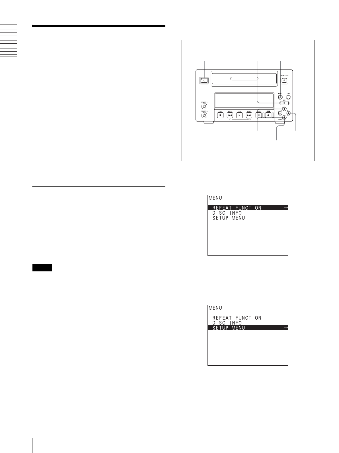
Selecting Either NTSC or PAL Video
Select the proper video signal system corresponding to
the one used in your area.
11,12
10
2,4,9
1
3,5,6,8
4,6,7
1
Press the MENU button.
The TOP menu appears.
Signal System
When you use the unit for the first time, you should
select the video signal system. The TV SYSTEM sub
menu of the ENHANCED MENU of the SETUP MENU
allows you to select either the NTSC or PAL video
signal system.
For detailed information on menu operations, see
“Basic Menu Operations” (page 50).
Note
At the factory setting, the NTSC video signal is selected
as the default. Even if your monitor does not correspond
to the video signal system currently selected, you can
carry out the menu operations using the main display
section of the front panel display.
2
Select “SETUP MENU” by pressing the V or v
button.
“SETUP MENU” is highlighted.
16
Setup Preparation
3
Press the b button.
Page 17
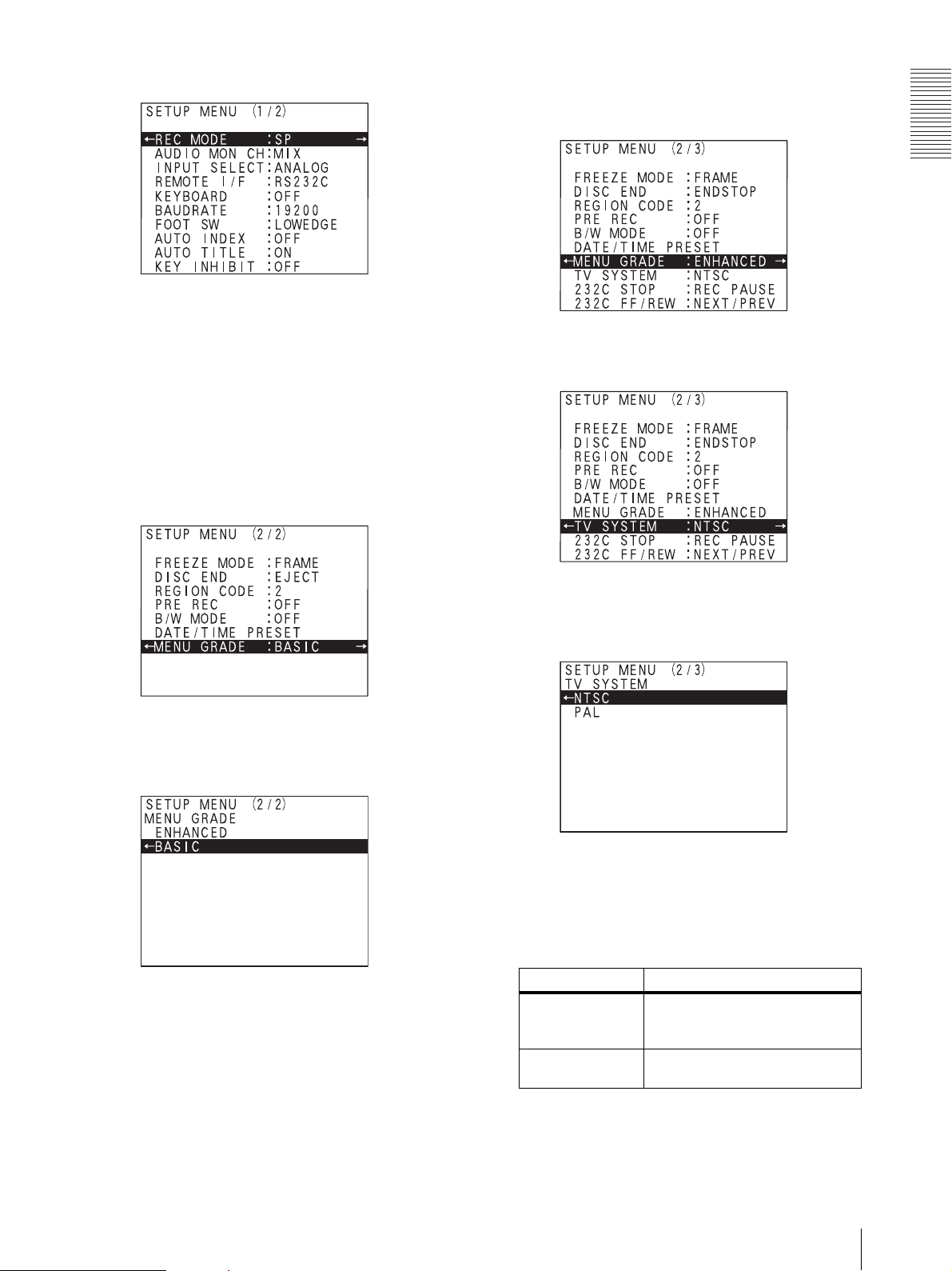
The SETUP MENU appears.
4
Select “MENU GRADE” from the SETUP MENU
display.
Each time you press the v or V button, the
highlighted cursor moves down or up item by item.
When the highlighted cursor reaches the last item
“KEY INHIBIT,” press the v button again. The
next page of the SETUP MENU appears.
Press the v button several times until “MENU
GRADE” is highlighted.
The following display appears when enhanced
menu items have been added under the last item of
the basic setup menu.
7
Select “TV SYSTEM” by pressing the v button.
Overview
5
Press the b button.
The following display appears.
6
Select “ENHANCED” by pressing the v button.
Then, with “ENHANCED” highlighted, press the B
button.
8
Press the b button.
The TV SYSTEM sub menu appears.
9
Select the desired video signal system by pressing
the V or v button.
The selected video signal system is highlighted.
TV SYSTEM Content
NTSC To record or play back with the
PAL To record or play back with the PAL
NTSC video signal system. (Factory
setting)
video signal system.
10
Press the SET button.
Setup Preparation
17
Page 18
Overview
The message “NOW SAVING....” appears and the
unit starts to save the setting.
When saving is completed, the message disappears.
Then, “TV SYSTEM WAS CHANGED PLEASE
POWER OFF.” appears on the monitor display, and
“POWER OFF!” appears on the front panel display.
Note
The TV system is not changed even if you push the
SET button. Be sure to turn the power of the unit off
and on as described in steps 11 and 12 to change the
system.
11
Press the 1 (power) switch on the front panel to
turn the power off.
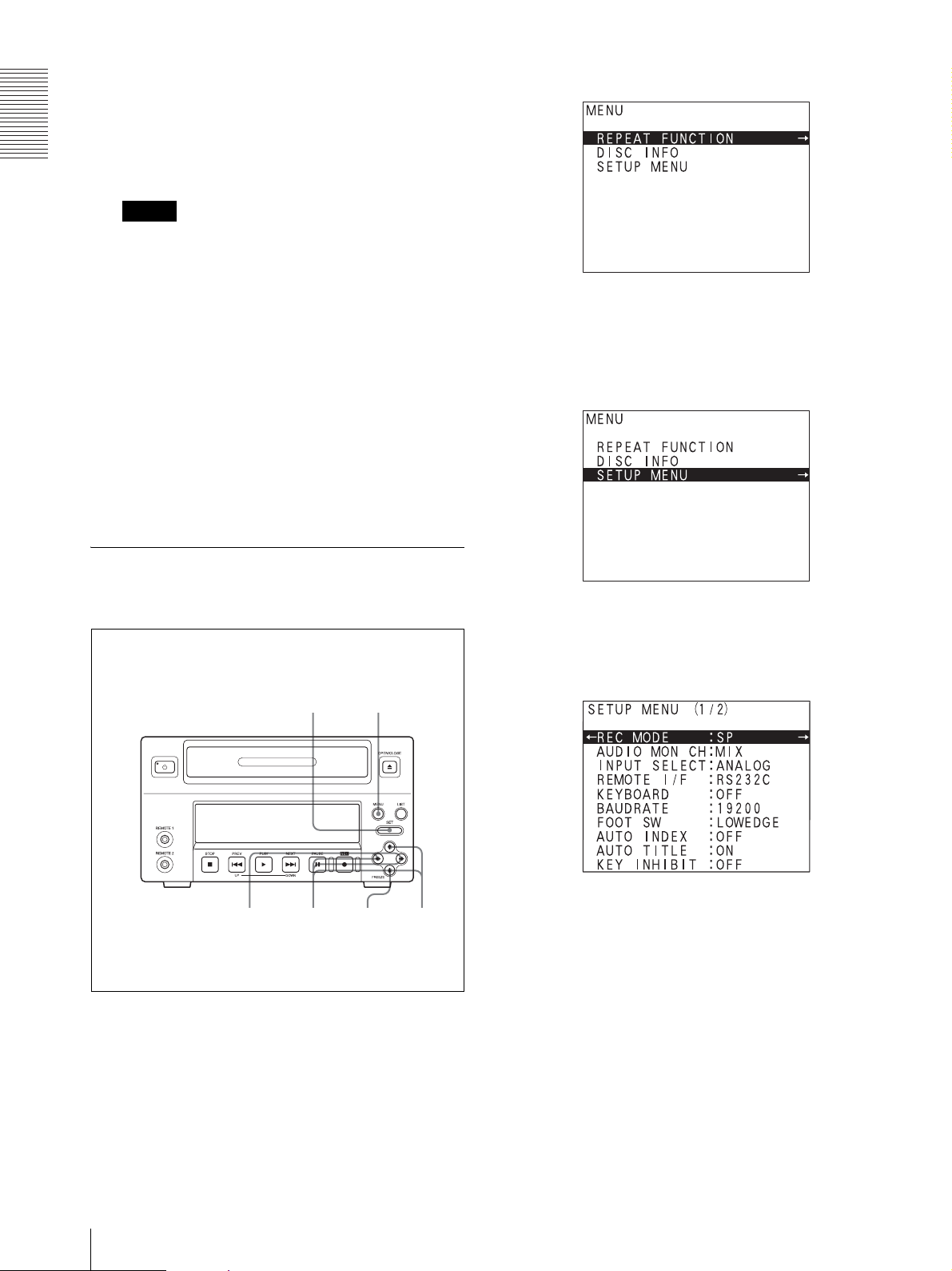
The TOP menu appears.
2
Select “SETUP MENU” by pressing the V or v
button.
The message “Good Bye” appears on the front
panel display. Then, the front panel display goes
off, the power is turned off and the unit enters the
standby mode.
12
Press the 1 (power) switch again to turn the power
on.
Setting the Date and Time
The DATE/TIME PRESET sub menu of the SETUP
MENU allows you to set the date and time.
9
1
“SETUP MENU” is highlighted.
3
Press the b button.
The SETUP MENU appears.
1
18
Press the MENU button.
Setup Preparation
3,5
6
4
2,7
4
Select “DATE/TIME PRESET” from the SETUP
MENU display.
Each time you press the v or V button, the
highlighted cursor moves down or up one by one.
When the highlighted cursor reaches the last item
pressing the v button, press the v button again. The
next page of the SETUP MENU appears.
Page 19
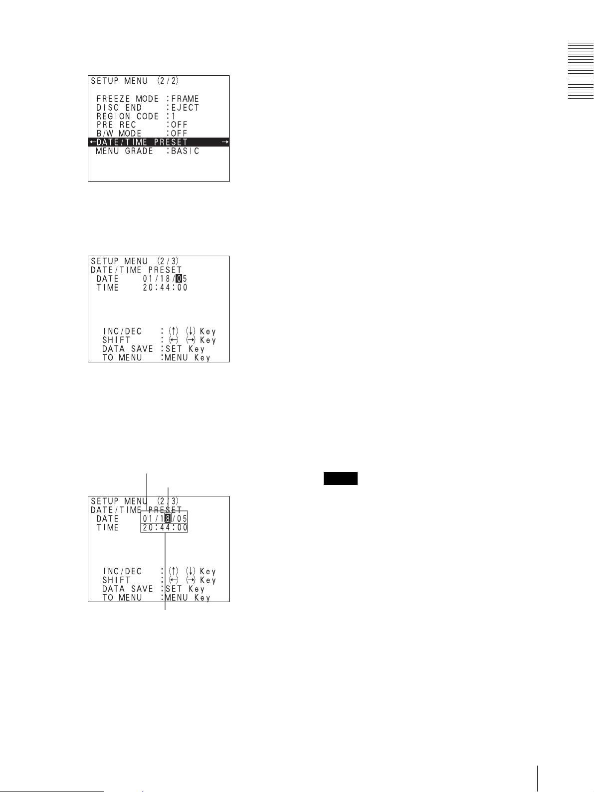
Press the v button several times until “DATE/TIME
PRESET” is highlighted.
5
Press the b button.
The DATE/TIME PRESET sub menu appears.
you press the B button, the rightmost digit of the
date column is highlighted.
Front panel display during menu operation
The date column appears when you set the date in
the date column on the DATE/TIME PRESET sub
menu. And the time column appears when you set
the time in the time column.
7
Change the numeric value by pressing the V or v
button.
Press the V button to increase a value.
Press the v button to decrease a value.
8
Set the remaining date and time values by repeating
steps 6 and 7.
9
Press the SET button when you have completed
setting the date and time.
The date and time values set are executed.
The message “NOW SAVING...” appears and the
unit starts to save the setting.
When the saving is completed, the message
disappears and the unit returns to the normal
display.
Overview
6
Select the digit to be set by pressing the B or b
button.
Press the B or b button until the digit you want to
change is highlighted.
Date display (month/date/year)
To move the cursor between the date
column and the time column
If you press the b button when the rightmost digit
of the date column is highlighted, the leftmost digit
of the time column is highlighted. When the
leftmost digit of the time column is highlighted, if
Highlighted display (digit to be
changed)
Time display
To cancel the date/time setting without
changing any values
Press the MENU button. The unit returns to the (2/
2) or (2/3) SETUP MENU display one level higher
than the current one. The setting is cancelled. Press
the MENU button again. The unit exits the menu
display and returns to the normal display.
Note
In this case, the message “ABORT!’ will not
appear.
Setup Preparation
19
Page 20

Overview
Selecting the Remote Interface
The REMOTE I/F sub menu of the SETUP MENU
allows you to select the interface to be used to control
the unit remotely.
The factory setting is RS-232C.
The SETUP MENU appears.
1
Press the MENU button.
The TOP menu appears.
7
3,5
1
2,4,6
4
Select “REMOTE I/F” by pressing the v button.
5
Press the b button.
The REMOTE I/F sub menu appears.
2
3
20
Select “SETUP MENU” by pressing the V or v
button.
“SETUP MENU” is highlighted.
Press the b button.
Setup Preparation
6
Select the desired remote interface by pressing the
V or v button.
The selected remote interface is highlighted.
Item Interface
RS232C To control the unit from external
iLINK To control the unit from external
USB To control the unit from external
equipment connected to the RS232C connector.
equipment connected to the i.LINK
connector.
equipment connected to the USB
connector.
a)
b)
c)
(Factory setting)
Page 21

a) This protocol is compatible with the SVO-
9500MD video cassette recorder protocol.
b) This setting is not related to the setting for the
input signal.
c) This protocol is equivalent to the RS-232C
protocol.
7
Press the SET button.
The message “NOW SAVING...” appears and the
unit starts to save the setting.
When the saving is completed, the message
disappears and the unit returns to the normal
display.
The remote interface setting of the unit is set to the
one selected in step 6.
Overview
Setup Preparation
21
Page 22

Recording
Recording
Handling Discs
Usable Discs
You can use the DVD+RW discs corresponding to quad
speed.
Note
You can use discs for both data and video.
Formatting discs
An unused disc requires no formatting operation. The
disc is automatically formatted when loaded into the
unit.
When you use a disc formatted by a computer or
recorded by using other DVD equipment, format the
disc using the FORMAT sub menu of DISC INFO.
Storage
• Do not store discs where they may be subjected to
direct sunlight, or in other places where the
temperature or humidity is high.
• Store discs in their cases.
• Finger prints or dust accumulated on the disc cause
deterioration of picture quality. Keep the disc clean.
Care of the discs
• Clean the disc with a soft cloth, wiping it from the
center out. If the dust is heavy, wipe it with a soft cloth
moistened with water, then wipe off the water with a
dry cloth.
• Do not use solvents such as benzene, thinner,
commercially available record cleaners, or anti-static
spray. Using these products may damage discs.
Note
When a recorded disc is formatted, all the data on the
disc is erased.
For detailed information on how to format a disc, see
“Formatting a Disc” on page 33.
Notes on Handling
Handling
• Do not touch the recording or playback surface of the
disc. Handle the disc by its edge.
• Do not use the following types of disc. Doing so may
cause the unit to malfunction.
– A disc on which a paper label or a seal is attached
– A disc on which the glue of cellophane tape or a
label, or on which a portion of a label still remains
– A cracked disc
– A cracked disc which has been mended using glue
(or a similar substance)
Loading and Unloading Discs
Loading a disc
1
1
Press the 1 (power) switch to turn the power on.
The message “Welcome” appears on the front panel
display.
The message changes to “Now loading...,” and then
“NO DISC!” lights. Proceed to the next operation.
Note
If the 1 (power) is not turned on and the front panel
display does not light even if you press the power
3
2,4
22
Handling Discs
Page 23

switch, check whether the MAIN POWER switch
on the rear panel is set to the ] (on) side.
For detailed information on how to turn the power
on or off, see “Turning the Power On/Off” on page
15.
2
Press the OPEN/CLOSE button.
Unloading a disc
1
Press the OPEN/CLOSE button with the power
turned on.
The disc tray opens.
2
Remove the disc.
The disc tray opens.
The message changes to “OPEN” on the front panel
display.
3
Place the disc on the tray.
With the recording/playback surface facing
down
4
Press the OPEN/CLOSE button. Or push the disc
tray lightly.
3
If you do not wish to load another disc, press the
OPEN/CLOSE button to close the disc tray.
Recording
The disc tray closes.
The DISC IN display blinks and the message “Now
loading...” appears on the front panel display.
DISC IN display
Go to the next step, after the message “Now
loading...” disappears and the DISC IN display
stops blinking.
If you load discs which cannot be used with the
unit
The message “Not Supported!” appears.
In such a case, unload the disc and insert a disc that can
be used with the unit.
Handling Discs
23
Page 24

Recording
The SETUP MENU appears.
Preparations for Recording
Selecting Input Signals
The INPUT SELECT sub menu of SETUP MENU
allows you to select the input signal to be recorded.
1
Press the MENU button.
The TOP menu appears.
6
1
2,3,5
2,4
3
Select “INPUT SELECT” by pressing the V or v
button.
4
Press the b button.
The INPUT SELECT sub menu appears.
2
Select “SETUP MENU” by pressing the V or v
button and press the b button with “SETUP
MENU” highlighted.
24
Preparations for Recording
5
Select the desired input signal by pressing the V or
v button.
Input signal Setting
ANALOG To record an analog signal input to
i.LINK To record a standard DV digital
When an analog input signal is selected:
When an S video cable is connected to the SVIDEO IN connector of the unit, the S video signal
is selected regardless of whether an S video signal
the VIDEO IN or S-VIDEO IN
connector. (Factory setting)
signal input to the DV IN (i.LINK)
connector.
Page 25

is input or not, taking precedence over a composite
video signal input to the VIDEO IN connector.
“S-VIDEO” appears on the front panel display.
6
Press the SET button.
The message “NOW SAVING...” appears and the
unit starts to save the setting.
When the saving is completed, the message
disappears and the unit returns to the normal
display.
The input signal is executed.
2
Select “SETUP MENU” by pressing the V or v
button and press the b button with “SETUP
MENU” highlighted.
Recording
Selecting the Recording Mode
The unit employs three different recording modes.
The REC MODE sub menu of SETUP MENU allows
you to select the recording mode.
1
Press the MENU button.
5
2,4
1
3
The SETUP MENU appears.
3
Confirm that the REC MODE is highlighted and
press the b button.
The REC MODE sub menu appears.
The TOP menu appears.
4
Select the desired recording mode pressing the V or
v button.
Recording
mode
HQ To record in high-quality
SP To record in standard
LP To record for long time. About 3 hours
5
Press the SET button.
Setting Maximum
recording
time
About 1 hour
recording mode.
About 2 hours
mode. (factory setting)
Preparations for Recording
25
Page 26

The message “NOW SAVING...” appears and the
unit starts to save the setting.
When the saving is completed, the message
disappears and the unit returns to the normal
display.
The recording mode is executed.
Recording
The unit allows you to record up to 49 titles on one disc.
Also, you can mark indexes at desired points during
recording.
When you record additional data on an already recorded
disc, the unit starts from the beginning of the blank
portion of the disc.
Recording
Notes
• If you load a disc which is full, a disc on which 49
titles have already been recorded, and so on, you
cannot record any data. Be sure to confirm the disc
before using it.
• When the remaining time of the disc becomes five
minutes, the main display section of the front panel
display (TITLE/CHAP/time indicator) blinks.
• Before performing the important recording, be sure to
try to record whether or not the unit records correctly.
Recording Titles
1
3
2,4
26
Recording
6
1
Press the 1 (power) switch to turn the power on.
The message “Welcome” appears on the front
panel.
When the message changes to “Now loading...,”
and then to “NO DISC!,” go to the next operation.
Note
If the power is not turned on and the front panel
display does not light even if you press the 1
(power) switch, check whether the MAIN POWER
switch on the rear panel is set to the ] (on) side.
5
Page 27

For detailed information on how to turn the power
on or off, see “Turning the Power On/Off” on page
15.
The titles are numbered in the sequence they are
recorded.
2
Press the OPEN/CLOSE button.
The disc tray opens.
The message changes to “OPEN” on the front panel
display.
3
Place the disc on the tray.
With the recording/playback surface facing
down
Title 1
Recording
starts
Recording
stops
Recording
starts
Title 2
Recording
stops
Recording
starts
Title 3
Recording
stops
To pause during recording
Press the XPAU S E butt o n.
To resume recording, press the XPAUSE button again.
Notes
• At the beginning of recording, an index is marked
automatically. Also, indexes are marked whenever
you press the XPAUS E bu tto n .
• When the unit is remotely controlled with the RS232C remote interface, the STOP command works as
the pause task or stop recording task. Which task is
effective depends on the setting of the 232C STOP
item (see page 49) of the ENHANCED MENU of the
SETUP MENU.
Recording
4
Press the OPEN/CLOSE button. Or push the disc
tray lightly.
The disc tray closes.
The DISC IN display blinks and the message “Now
loading...” appears on the front panel display.
When the DISC IN display stops blinking, go to
step 5.
5
Press the zREC button.
The unit starts recording of one title.
6
To stop recording that title, press the xSTOP
button.
7
Repeat recording of the remaining titles by
repeating steps 5 and 6.
If buttons on the front panel do not
function even if you push them
The KEY INHIBIT item (see page 47) of the SETUP
MENU is set to “ON.”
Thus, the key-lock function is activated so that all
buttons except the MENU button, the LIST button, the
power switch, and the OPEN/CLOSE button are
deactivated to prevent you from pressing buttons
accidentally.
To re-activate the buttons, set the KEY INHIBIT item to
“OFF.”
However, when the unit is in menu operation status, you
can use the B, b, V, v, and SET buttons.
Marking Indexes During Recording
You can mark indexes at desired points during
recording. This allows you to search for the desired
points instantly during playback, and also to play a
segment specified by two points in succession.
You can mark up to 254 indexes on one disc and up to 99
indexes within one title.
You can mark indexes using the following three
methods.
To use the XPAUSE button of the unit
Press the XPAUSE button on the front panel of the unit.
Recording
27
Page 28

Recording
To use the SVRM-100A remote control unit
Press the MARK button on the SVRM-100A remote
control unit (not supplied).
For detailed information on how to mark indexes, see
“Marking Indexes” on page 58.
To mark indexes automatically
Indexes are automatically marked every five minutes
when the AUTO INDEX (see page 47) sub menu of the
SETUP MENU is set to ON.
Note
The TOP menu appears.
You can mark up to 254 indexes on one disc and up to 99
indexes within one title.
When the number of indexes exceed the above
limitation, an alarm message appears.
For detailed information on alarm messages, see
“Alarm Messages” on page 52.
To make new titles automatically
The AUTO TITLE sub menu of the SETUP MENU
allows you to make a new title when the number of
indexes in one title exceeds 99.
For details, see “AUTO TITLE” on page 47.
Segment between the indexes
The segment between the indexes is called a chapter.
Title 3
Chapter1
Indexes
Title 1
Chapter 2
Chapter 3
Title 2
Chapter1 Chapter 2 Chapter1
2
Select “SETUP MENU” by pressing the V or v
button and press the b button with “SETUP
MENU” highlighted.
The SETUP MENU appears.
3
Select “FOOT SW” by pressing the V or v button.
Using a Foot Switch
A foot switch (not supplied) allows you to start or pause
recording.
The operation required for starting or pausing the
recording depends on the setting of the FOOT SW sub
menu of the SETUP MENU.
Note
To stop recording when using a foot switch, press the
xSTOP button on the front panel of the unit.
1
Press the MENU button.
28
Recording
4
Press the b button.
The FOOT SW sub menu appears.
Page 29

5
Select the desired mode by pressing the V or v
button.
Mode Setting
LOW EDGE To start recording when you push
HIGH EDGE To start recording when you push
LOW ACTIVE While you hold the foot switch
6
Press the SET button.
the foot switch, or to pause
recording during recording.
Even if you release the foot switch,
the recording or pause recording
status remains in effective. (Factory
setting)
the foot switch and release it, or to
pause recording during recording.
The unit does not change from one
operation to another when you push
the foot switch.
down, the unit records. When you
release the foot switch, the unit
pauses.
The message “NOW SAVING...” appears and the
unit starts to save the setting.
When the saving is completed, the message
disappears and the unit returns to the normal
display.
Notes
• Be sure to turn off the power of the unit by using the
1 (power) switch on the front panel of the unit.
For detailed information on how to turn off the power
of the unit, see “Turning the Power Off” on page 15.
• When not using the RM-P110, be sure to set the
KEYBOARD sub menu of the SETUP MENU to OFF
(see page 47).
To add information to the title or edit title
information
The TITLE INFO display of the title menu allows you to
edit title information.
Title name
Title information (data of 2048 bytes)
Recording
Adding Information to Titles
When you record data, the recording month/date/year/
hour/minute/second (example: 01/06/04 17:25:19) is
recorded automatically.
Also, the RM-P110 remote control unit (not supplied)
allows you to change the title name and to record data of
2048 bytes every title using the keyboard of the RMP110. Thus, you can record additional information for a
title.
To use an RM-P110 (not supplied) as a
keyboard for editing/adding title name and
information
You should carry out the following operation and menu
settings:
• Connect the RM-P110 to the RS-232C connector of
the unit.
• Set the REMOTE I/F sub menu (see page 47) of the
SETUP MENU to RS232C.
• Set the KEYBOARD sub menu (see page 47) of the
SETUP MENU to ON.
You can enter characters in overwrite mode. Use the
ESC key for the backspace function.
For detailed information, see “Verifying/Editing
Information About the Title” on page 42.
When you record using equipment such as external
equipment, data is recorded via the communication
protocol.
Pre Rec Function
When the PRE REC sub menu of the SETUP is set to
“ON,” the unit saves the last 5 seconds of video data in
the inernal memory. This function allows the unit to start
recording the last 5 seconds of video data saved
previously for continuity.
1
Press the MENU button.
Recording
29
Page 30

Recording
The TOP menu appears.
2
Select “SETUP MENU” by pressing the V or v
button, and press the b button with “SETUP
MENU” highlighted.
The SETUP MENU appears.
5
Select the desired mode by pressing the V or v
button.
Mode Setting
OFF To record the video signal promptly
ON To start recording using the last 5
6
Press the SET button.
The message “NOW SAVING...” appears and the
unit starts to save the setting.
When the saving is completed, the message
disappears and the unit returns to the normal
display.
The setting for the previous recording is executed.
after you start recording. (Factory
setting)
seconds of video data saved
previously.
When the Disc Becomes Full During Recording
3
Select “PRE REC” by pressing the V or v button.
4
Press the b button.
The PRE REC sub menu appears.
At the factory setting, the unit stops recording
automatically and the disc tray opens.
The DISC END sub menu of the SETUP MENU allows
you to change this setting.
1
Press the MENU button.
The TOP menu appears.
2
Select “SETUP MENU” by pressing the V or v
button and press the b button with “SETUP
MENU” highlighted.
30
Recording
Page 31

The SETUP MENU appears.
3
Select “DISC END” by pressing the V or v button.
The message “NOW SAVING...” appears and the
unit starts to save the setting.
When the saving is completed, the message
disappears and the unit returns to the normal
display.
The setting is executed.
Recording
4
Press the b button.
The DISC END sub menu appears.
5
Select the desired disc end mode by pressing the V
or v button.
Mode Setting
GOTO TOP To return to the beginning of the
END STOP To return to the beginning of the last
EJECT To stop recording and eject the disc
disc.
title, and end recording
automatically. However, the disc is
not ejected, and the disc remains in
the tray.
automatically. (Factory setting)
6
Press the SET button.
Recording
31
Page 32

Recording
Finalizing a Disc
There is a case where a disc recorded on this unit must
be finalized to play it on other equipment compatible
with DVD+RW equipment. Proceed as follows to
finalize the disc.
Even if the disc is finalized, you can use that disc for
recording again or you can edit data recorded on the
disc.
1
Load the disc to be finalized into the unit.
2
Press the MENU button.
The FINALIZE display appears.
The TOP menu appears.
3
Select “DISC INFO” by pressing the V or v button,
and press the b button with “DISC INFO”
highlighted.
The DISC INFORMATION sub menu appears.
5
Select “EXEC” pressing the V or v button. Then,
press the SET button.
The message “READY?” appears.
6
Press the SET button.
The message “FINALIZING THE DISC. PLEASE
WAIT.” appears, and finalization is started.
When finalization is completed, the message
changes to “COMPLETE!,” and the unit exits the
menu and returns to the normal display.
7
Remove the disc.
32
4
Press the V or v button to select “FINALIZE” and
press the b button with “FINALIZE” highlighted.
Finalizing a Disc
Page 33

Formatting a Disc
You can erase all the data recorded on the DVD+RW
disc and format that disc so as to be able to use it with
the unit.
Note
When a recorded disc is formatted, all the data, such as
title names is erased. You cannot resume it to the status
before formatted.
1
Load the disc to be formatted in the unit.
2
Press the MENU button.
The TOP menu appears.
The FORMAT display appears.
5
Select “EXEC” by pressing the V or v button, and
then press the SET button.
The message “READY?” appears.
To quit formatting a disc
Select “ESC,” and then press the SET button with
ESC highlighted.
Or press the MENU button.
6
Press the SET button.
Recording
3
Select “DISC INFO” by pressing the V or v button,
and press the b button with “DISC INFO”
highlighted.
The DISC INFORMATION sub menu appears.
4
Select “FORMAT” by pressing the V or v button,
and press the b button with “FORMAT”
highlighted.
The message “FORMATTING THE DISC.
PLEASE WAIT.” appears and formatting is started.
When formatting is completed, the message
changes to “COMPLETE!,” and the unit exits the
menu and returns to the normal display.
7
Remove the disc.
Formatting a Disc
33
Page 34

Playback
2
Press the OPEN/CLOSE button.
The disc tray opens.
The message changes to “OPEN” on the front panel
display.
Playback
3
Place the disc to be played on the tray.
4
Press the OPEN/CLOSE button.
Usable Discs
You can use the 4 x DVD+RW discs.
Note
The recorded discs may not be able to be played back
Playback
due to scratch on the disc, dust accumulated on the disc,
conditions recorded or recording equipment.
The disc tray closes.
The DISC IN display blinks and the message “Now
loading...” appears on the front panel display.
Go to step 5, after the message Now loading...”
disappears and the DISC IN display lights up.
5
Press the BPLAY button.
Playback starts.
Playback a Disc
Note
For a moment, the picture is frozen and audio
playback stops between titles.
3
1
2,4
To stop playback
Press the xSTOP button.
Fast Forward or Reverse Playback
5
xSTOP button
1
Press the 1 (power) switch to turn the power on.
The message “Welcome” appears on the front
panel.
When the message changes to “Now loading...”,
and then to “NO DISC!.”, go to the next operation.
Note
If the power is not turned on and the front panel
display does not light even if you press the 1
(power) switch, check whether the MAIN POWER
switch on the rear panel is set to the ] (on) side.
For detailed information on how to turn the power
on or off, see “Turning the Power On/Off” on page
15.
To view fast forward playback
Press the >NEXT/DOWN button with the BPLAY
button held down. This allows you to view fast forward
playback at a speed three times the speed of normal
playback.
To view reverse playback
Press the .PREV/UP button with the BPLAY button
held down. This allows you to view fast reverse
playback at a speed three times the speed of normal
playback.
Adding Indexes During Playback
You can add indexes using the SVRM-100A remote
control unit.
For detailed information on how to add indexes, see
“Using an SVRM-100A Remote Control Unit (Not
Supplied)” on page 57.
34
Playback
Page 35

Searching for Desired Point
Jumping to a Desired Title
The B or b button allows the unit to jump to the title
before or after the title currently being played.
Jumping to a Desired Chapter
The .PREV/UP or >NEXT/DOWN button
allows the unit to jump to the chapter before or after the
chapter currently being played.
Playback
>NEXT/DOWN button
.PREV/UP button
1
1
Press the BPLAY button.
Playback starts.
2
Press the B or b button to jump.
When you press the B button:
When you press this button once, the unit jumps to
the start point of the title currently being played.
When you press this button twice, the unit jumps to
the start point of the previous title of the title
currently being played.
When you press the b button:
When you press this button once, the unit jumps to
the start point of the next title.
2
When you use the >NEXT/DOWN button:
When you press this button once, the unit jumps to the
start point of the next chapter.
When you use the .PREV/UP button:
When you press this button once, the unit jumps to the
start point of the chapter currently being played.
When you press this button twice, the unit jumps to the
start point of the previous chapter.
Example
Playback direction
ABC D
Chapter 1
a) The last chapter recorded on a disc
Chapter 2
PREV
Chapter 3
Chapter 4
NEXT
P
a)
When you press the .PREV/UP button or the
>NEXT/DOWN button at the current position (point
P), the unit behaves as follows:
When the .PREV/UP button is pressed once: Jumps
to point C.
When the .PREV/UP button is pressed twice: Jumps
to point B.
When the >NEXT/DOWN button is pressed once:
Jumps to point D.
Searching for Desired Point
35
Page 36

When the >NEXT/DOWN button is pressed twice:
When the target point is the end of the last chapter, the
unit jumps to the beginning of the last chapter. Thus, in
this case, the unit jumps to point D.
Repeat Playback
You can conduct the following repeat playback
operations using the menu.
• Repeat playback between two points (A-B repeat)
• Repeat playback of the chapter currently being played
• Repeat playback of the title currently being played
Repeat Playback Between Two Points (A-B Repeat)
You can conduct repeat playback of a certain section
specified by two points.
Playback
Setting points A and B
Proceed as follows to set points A and B and conduct
repeat playback.
1
Load the disc to be played.
2
Press the MENU button during playback.
The TOP menu appears.
3
Select “REPEAT FUNCTION” by pressing the V
or v button, and press the b button with “REPEAT
FUNCTION” highlighted.
The REPEAT FUNCTION display appears.
36
Repeat Playback
4
Select “REPEAT A-B” by pressing the V or v
button, and press the b button with “REPEAT A-B”
highlighted.
Page 37

The REPEAT A-B display appears.
5
Select “A-B SET” by pressing the v button.
Point A is set and “A” disappears. Then, “B” is
displayed as a white letter.
“A” disappears, and “B” is
highlighted in white.
If you return to the previous menu display
by pressing the B button after setting only
point A
The point A set is cancelled. The points A and B
previously set are retained. If you press the b
button again, you can start setting the point B.
8
Press the SET button at the instant when the picture
comes to the point you want to set as point B.
Playback
6
Press the SET button.
Playback starts, and “A” is displayed as a white
letter at the bottom left of the screen.
“A” is highlighted in white.
7
Press the SET button at the instant when the picture
comes to the point you want to set that as point A.
The point B is set and “B” disappears. The repeat
playback starts between the points A and B set.
Those points A and B are stored until you set new
points A and B or until the disc is unloaded.
Note
When erasing a title (see page 44) or formatting a
disc (see page 33), points A and B set are cleared.
Stopping repeat playback between points
A and B
The following two methods are available to stop repeat
playback between two points.
•Using the B, b, .PREV/UP, or >NEXT/
DOWN button
• Using a menu operation
To stop repeat playback using the B, b,
.PREV/UP, or >NEXT/DOWN button
Jump to a title or a chapter located outside of the section
specified by the A and B points using the B, b,
.PREV/UP, or >NEXT/DOWN button.
To stop repeat playback by menu operations
1
Follow the procedure in steps 1 to 2 described in
“Repeat Playback Between Two Points (A-B
Repeat)” on page 36 to display the REPEAT
FUNCTION item.
Repeat Playback
37
Page 38

2
With “CLEAR REPEAT” highlighted, press the
SET button.
The unit exits the A-B repeat mode and stops
playback
Playback
Conducting repeat playback of the
The TOP menu appears.
2
Select “REPEAT FUNCTION” by pressing the V
or v button, and press the b button with “REPEAT
FUNCTION” highlighted.
The REPEAT FUNCTION display appears.
existing points A and B
1
Follow the procedure in steps 2 to 3 described in
“Repeat Playback Between Two Points (A-B
Repeat)” on page 36 to display the REPEAT A-B
item.
2
With “REPEAT” highlighted, press the SET button.
Repeat playback between points A and B starts.
When either point A or B has not yet been
set
The error message “NO AB POINT!” appears on
the front panel display and “NO A.B POINT. SET
THE A & B POINT” appears on the monitor
display..
Repeat Playback of a Chapter
You can conduct repeat playback of a desired chapter.
Proceed as follows to specify a chapter and conduct
repeat playback.
3
Select “REPEAT CHAPTER”, by pressing the V or
v button.
4
Press the SET button at the instant when the chapter
that you want to repeat comes up.
Repeat playback of the current chapter starts.
To stop repeat playback of the chapter
Perform the operation descried in “Stopping repeat
playback between points A and B” on page 37.
38
1
Press the MENU button.
Repeat Playback
Repeat Playback of a Title
You can conduct repeat playback of a desired title.
Page 39

Proceed as follows to specify a title and conduct repeat
playback.
1
Press the MENU button.
Playing From the TITLE LIST Display
The TOP menu appears.
2
Select “REPEAT FUNCTION” by pressing the V
or v button, and press the b button with “REPEAT
FUNCTION” highlighted.
The REPEAT FUNCTION display appears.
You can select the desired chapter and play it back using
the title list.
1
Load the disc to be played.
2
Press the LIST button.
The TITLE LIST display appears.
3
Select the title which has the chapter that you want
to display, by pressing the V or v button.
The following display of the selected title appears.
Playback
3
Select “REPEAT TITLE” by pressing the V or v
button.
4
Press the SET button at the instant when the title
that you want to repeat comes up.
Repeat playback of the current title starts.
To stop repeat playback of the title
Perform the operation descried in “Stopping repeat
playback between points A and B” on page 37.
When there are plural pages
There are two methods how to move to another
page.
For details, see “Displaying the next page” on page
40.
4
Select “PLAY” by pressing the V or v button, and
then press the b button.
Playing From the TITLE LIST Display
39
Page 40

The following display appears.
Verifying Information on a Disc
You can verify information on a disc.
Proceed as follows to display the DISC
INFORMATION display.
1
Load a disc and press the MENU button.
The TOP menu appears.
5
Select the chapter that you want to play, by pressing
the V or v button, and then press the SET button.
Playback
Playback of the selected chapter starts.
Displaying the next page
When there are plural pages of title list displayed in step
3 and chapter list displayed in step 4, the following two
methods are available to display another pages.
Using the V or v button
1
Highlight the last title or chapter on the current
page to go to the next page by pressing v button.
Each time you press the V or v button, the display
scrolls up or down by one line at a time.
2
Press the v button.
The new page appears.
Using the .PREV/UP or >NEXT/DOWN
button
To go back to the previous page: Press the .PREV/
UP button.
To move to the next page: Press the >NEXT/
DOWN button.
2
Press the V or v button to select “DISC INFO” and
press the b button with “DISC INFO” highlighted.
The DISC INFORMATION display appears.
You can very the following information on a disc.
40
Verifying Information on a Disc
Page 41

Item Function
DISC NAME To display the disc name.
MEDIA To display the media type (display
only).
TITLE COUNT To display the number of titles
recorded on a disc (display only).
REC DATE FIRST: Oldest recording date
among titles recorded in one disc.
LATEST: Latest recording date
among titles recorded in one disc.
(Both are only displayed)
DISC REMAIN To display the remaining recording
capacity in units of time for each
recording mode (display only).
FINALIZE To finalize a disc.
FORMAT To format a disc.
To display whole of the disc name
Press the V or v button to select “DISC NAME,”
and press the b button.
Press the b button.
Viewing Frozen Pictures
Viewing frozen pictures using buttons on
the unit
The following two methods are available to view a
frozen picture during playback.
• Pressing the XPAUSE button during playback
Playback stops and the picture at that point is frozen.
In this case, the frozen picture is a field picture.
To cancel to freeze picture and to play again:
Press the XPAUSE button again, or press the BPLAY
button.
Playback
• Pressing the v (FREEZE) button during
playback
You can view frame frozen pictures and frozen field
pictures in sequence. When you press the v button the
first time, the picture becomes a frame frozen picture.
When you press the v button the second time, the
frame frozen picture is replaced with the first field
frozen picture. When you press the v button the third
time, the first field frozen picture is replaced with the
second field frozen picture. Whenever you press the v
button, the frozen picture is replaced in this sequence.
The FREEZE MODE item (see page 48) of the
SETUP MENU allows you to decide whether the first
frozen picture is a frame frozen or field frozen picture.
To cancel to freeze picture and to play again:
Press the BPLAY button.
You can change the disc name on the above screen.
However, you cannot edit the disc name on this
unit. The RM-P110 (not supplied) is required.
You can edit the disc name using the RM-P110 (not
supplied) connected to the RS-232C connector.
For detailed information on the RM-P110, see “To
use an RM-P110 (not supplied) as a keyboard for
editing/adding title name and information” on page
29.
To return to the previous DISC INFORMATION
display
Press the MENU button.
When the unit is controlled using the
SVRM-100A remote control unit
To freeze the playback picture
Press the FREEZE button during playback.
When you press the FREEZE button the first time, the
picture becomes a frame frozen picture.When you press
the FREEZE button the second time, the frame frozen
picture is replaced with the first field frozen
picture.When you press the FREEZE button the third
time, the first field frozen picture is replaced with the
second field frozen picture. Whenever you press the
FREEZE button, the frozen picture is replaced in this
sequence.
The FREEZE MODE item (see page 48) of the SETUP
MENU allows you to decide the first frozen picture to
frame one or field one.
To cancel to freeze picture and to play again
Press the BPLAY button.
For detailed information on the remote control unit, see
“Using an SVRM-100A Remote Control Unit (Not
Supplied)” on page 57.
Viewing Frozen Pictures
41
Page 42

Editing
Editing
Editing Titles
The TITLE LIST menu allows you to carry out the
following editing tasks on titles.
• Verifying information about titles and editing
titles
You can verify information about titles and edit titles
as required.
For details, see “Verifying/Editing Information About
the Title” on page 42.
• Protecting a title
You can protect titles from accidental erasure or
editing.
For details, see “Protecting a Title” on page 43.
• Erasing a title
You can erase unnecessary titles.
For details, see “Erasing a Title” on page 44.
Verifying/Editing Information About the Title
The TITLE LIST menu allows you to verify information
about the desired title. Also, you can edit the name and
title information on the TITLE NAME and TITLE INFO
displays.
Note
To edit information about titles, the RM-P110 remote
control unit (not supplied) is required.
1
Load the disc to be edited.
2
Press the LIST button.
3
Select the title with information you want to verify
by pressing the V or v button, and press the b
button.
The following display appears.
When there are plural pages in the title list
The following two methods are available to move to
another pages.
• Using the V or v button
Each time you press the V or v button, the display
scrolls up or down by one line at a time.
Highlight the last title on the current page by
pressing v button. When the last title is
highlighted, press the v button.
The new page appears.
• Using the .PREV/UP or >NEXT/
DOWN button
To go back to the previous page: Press the
.PREV/UP button.
To move to the next page: Press the >NEXT/
DOWN button.
4
Select “TITLE NAME” to verify or edit the title
name, or select “TITLE INFO” to view or edit the
title information by pressing the V or v button.
To verify or edit the title name
42
The TITLE LIST display appears.
The list of titles is displayed.
Editing Titles
Page 43

To verify or edit the title information
keyboard for editing/adding title name and
information” on page 29.
When you finish editing:
Press the SET button on the unit after carrying out
editing task using the RM-P110.
The message “SAVING...” appears on the front
panel display while the title name or title
information is being saved. On the monitor display,
“THIS TITLE IS CHANGING INFORMATION.
PLEASE WAIT” appears while the tile name or
title information is being saved.
5
Press the b button.
The name or information of the title selected in step
3 is displayed.
When “TITLE NAME” is selected:
Title name currently displayed
Title name automatically recorded on the disc
When “TITLE INFO” is selected:
Title name
To verify information from another title
Press the LIST button. The screen returns to the one
in step 3.
Then, push the B button so that the screen returns to
the one in step 2.
Finally, repeat steps 2 and 3 to verify information
from another title.
Protecting a Title
The TITLE LIST display allows you to protect titles
from accidental erasure or to prohibit indexes from
being added to or erased from titles.
Proceed as follows.
1
Load the disc on which titles that you want to
protect are recorded.
2
Press the LIST button.
TITLE LIST display appears.
The list of titles is displayed.
Editing
Title information
To edit the title name and information
You cannot edit titles and information on this unit.
To edit them, connect the RM-P110 remote control
unit (not supplied) to the unit.
For detailed information on how to use the RMP110, see “To use an RM-P110 (not supplied) as a
3
Select the title that you want to protect from the list
by pressing the V or v button. Then, press the b
button.
Editing Titles
43
Page 44

Editing
The following display appears.
When there are plural pages in the title list
The following two methods are available to move to
another page.
•Using the V or v button
•Using the .PREV/UP button or the
>NEXT/DOWN button
For details, see “When there are plural pages in the
title list” on page 42.
4
Select “PROTECT” by pressing the V or v button.
The current status
Setting Content
ON The title is protected.
OFF The title is not protected. (factory
7
Press the SET button.
setting)
Erasing a Title
Proceed as follows.
1
Load the disc on which titles that you want to erase
are recorded.
2
Press the LIST button.
The TITLE LIST display appears.
The list of titles is displayed.
5
Press the b button.
The setting display appears.
6
Select the desired setting pressing the V or v
button.
The name of the selected title
3
Select the title that you want to erase from the title
list by pressing the V or v button, and press the b
button.
The following display appears.
When there are plural pages in the title list
The following two methods are available to move to
another page.
• Using the V or v button
• Using the .PREV/UP button or the
>NEXT/DOWN button
For details, see “When there are plural pages in the
title list” on page 42.
44
Editing Titles
Page 45

4
Select “ERASE” by pressing the V or v button.
5
Press the b button.
The following display appears.
erase title 30 which is the last title currently recorded,
the remaining titles are title 1 to title 29. When you
record a title the next time, the new title number will be
30.
If you erase titles other than the last one, the capacity of
the disc does not change. However, the title numbers are
renumbered using the numbers of the titles which were
erase.
Editing
6
Select “EXEC” by pressing the V or v button.
7
Press the SET button.
The message “READY?” appears.
8
Press the SET button.
The message “ERASING THIS TITLE. PLEASE
WAIT” appears highlighted, and the unit starts
erasing the title selected.
Note
The unit can record up to 49 titles on one disc.
When the last title is erased, the capacity of the disc is
increased by the size of that title. When you erase a title,
adjustment is made to the title numbers based on where
the erased title was in the list of titles. For example, you
Editing Titles
45
Page 46

Menu
This menu allows you to repeat playback between two
points (A-B repeat), playback of the chapter and the
title.
Menu Configuration and the Menu List
The unit has two kinds of menus: one is the menu
displayed by pressing the MENU button, and the other
is the title list menu displayed by pressing the LIST
button.
This section describes the configuration and the list of
the menu displayed by pressing the MENU button.
For detailed information on menu operation, see“Basic
REPEAT FUNCTION menu
Menu Operations” on page 50. For detailed information
on the title list menu, see “Playing From the TITLE LIST
Display” on page 39.
About the front panel display during menu
operation
This manual uses the monitor display for explaining the
menu operation. The items currently highlighted on the
monitor display are displayed on the main display
Menu
section of the front panel display.
Whenever you push the B, b, V or v button, the display
changes.
Item Function
REPEAT A-B To play a segment specified by two points
REPEAT
CHAPTER
REPEAT TITLE To play the title currently being played
CLEAR REPEAT To stop the current repeat playback
(point A and point B) repeatedly
To play the chapter currently being
played repeatedly
repeatedly
DISC INFORMATION menu
The menu allows you to verify details of the disc,
finalize and format the disc.
Menu Configuration
Press the MENU button. The TOP menu appears.
The TOP menu is configured as follows.
• REPEAT FUNCTION menu
• DISC INFO menu
• SETUP MENU
For detailed information on menus, see the following
“Menu List” on page 46.
Menu List
This section describes menus displayed by pressing the
MENU button, using lists.
The setting surrounded with indicates the factory
setting.
Item Function
DISC NAME To display the disc name
MEDIA To display the media type (display only)
TITLE COUNT To display the number of titles recorded
on a disc (display only)
REC DATE FIRST: Oldest recording date among
titles recorded in one disc.
LATEST: Latest recording date among
titles recorded in one disc.
(Both are only displayed)
DISC REMAIN To display the remaining recording
capacity in units of time for each
recording mode (display only)
FINALIZE To finalize a disc
FORMAT To format a disc
46
Menu Configuration and the Menu List
Page 47

SETUP MENU
This menu allows you to perform various settings
depending on your circumstances to use the unit.
Item Function Setting
REC MODE To select a
AUDIO
MON CH
INPUT
SELECT
REMOTE I/F To select an
KEYBOARD To select
recording mode
To s e l e c t a
signal to be
output from the
MONITOR
AUDIO
connector on
the rear panel
To s e l e c t a
video and audio
input signals
interface to use
to control the
unit
whether or not
the keyboard of
the RM-P110
remote control
unit (not
supplied) is to
be activated
HQ: Records a high-quality
picture.
[SP]: Records in standard
mode.
LP: Records for a longer
time.
LCH: Outputs the audio
signal of audio channel 1.
RCH: Outputs the audio
signal of audio channel 2.
[MIX]: Outputs a mixed audio
signal from both channel 1
and channel 2.
[ANALOG]: Inputs the analog
signal to the VIDEO IN or SVIDEO IN connector.
iLINK: Inputs the digital
signal to the DV IN (i.LINK)
connector.
[RS232C]: Controls the unit
with equipment connected to
the RS-232C connector (a
protocol which is compatible
with the SVO-9500MD Sony
video cassette recorder
protocol).
i.LINK: Controls the unit
with equipment connected to
the DV IN (i.LINK)
connector.
USB: Controls the unit with
equipment connected to the
USB connector (a protocol
which is compatible with the
RS-232C protocol).
ON: Uses the keyboard.
[OFF]: Does not use the
keyboard.
Item Function Setting
BAUDRATE To select a
communication
speed (baud
rate) when
controlling the
unit by
equipment
connected to
the RS-232C
connector
FOOT SW To select the
AUTO
INDEX
AUTO
TITLE
KEY
INHIBIT
operation to be
carried out
when you press
or release the
foot switch (not
supplied)
To sele c t
whether or not
indexes are
automatically
marked during
recording
To sele c t
whether or not a
new title is
automatically
created when
the number of
indexes in one
title exceeds 99.
To deactivate
buttons to
protect them
from accidental
operation
except the
MENU, LIST,
1 (power), and
OPEN/CLOSE
buttons
9600 /[19200]/38400/57600/
115200
[LOW EDGE]: Starts
recording, or pauses
recording during recording,
when you press the foot
switch. Even if you release
the foot switch, the recording
or pause recording status
remains in effective.
HIGH EDGE: Starts
recording or pausing during
recording when you press and
release the foot switch. The
unit does not change from
one operation to another
when you press the foot
switch.
LOW ACTIVE: While you
hold the foot switch down,
the unit records. When you
release the foot switch, the
unit pauses.
a)
: Marks indexes
ON
automatically every 5
minutes.
[OFF]: Does not mark indexes
automatically.
[ON]: Creates a next title
automatically. It is
recommended to select this
setting when connecting VHS
equipment.
OFF: Does not create a next
title automatically.
ON: Activates the key lock
function.
[OFF]: Deactivates the key
lock function. All of the
buttons are effective.
Menu
Menu Configuration and the Menu List
47
Page 48

Item Function Setting
FREEZE
MODE
DISC END To select the
Menu
REGION
CODE
To select the
type of frozen
picture
displayed when
playback is
paused. (This is
effective only
when the v
button on the
front panel or
the FREEZE
button on the
SVRM-100A
remote control
unit (not
supplied) is
used)
operation when
the disc
becomes full
during
recording
To select the
region code for
playback
b)
[FRAME]: Displays a frame
frozen picture when you push
the button, then the first field
is frozen when you push the
button next, and then the
second field is frozen when
you push the button a third
time.
1ST FIELD: Whenever you
push the button, the frozen
picture displayed changes in
the sequence of the first field,
then the 2nd field, and then
the frame.
2ND FIELD: Whenever you
push the button, the frozen
picture displayed changes in
the sequence of the 2nd field,
then the frame, and then the
first field.
GOTO TOP: Returns to the
beginning of the disc.
END STOP: Returns to the
beginning of the last tile, and
end recording automatically.
However, the disc is not
ejected and remains in the
tray.
[EJECT]: Stops recording and
the disc is automatically
ejected.
[1]: Plays a disc recorded in
North America. (This region
code is not available for the
PAL video signal system.)
2: Plays a disc recorded in
Western Europe (PAL), the
Middle East (PAL), South
Africa (PAL) and Japan
(NTSC)
3: Southeast Asia including
Hong Kong
4: Central and South
America, and Australia (PAL)
5: Africa (NTSC), Eastern
Europe, Russia, Central Asia,
including India (PAL)
c)
Item Function Setting
B/W MODE To forcibly
switch the
signal process
mode of the
VIDEO IN,
VIDEO OUT
and S-VIDEO
OUT
connectors to
the black and
white signal
DATE/TIME
PRESET
MENU
GRADE
a) Indexes recorded automatically cannot be erased.
b) If the video signal system does not match the one used in your area, the
disc cannot be played back even if the correct region code is selected.
Set the video signal system to either NTSC or PAL on the TV SYSTEM
sub menu of the ENHANCED MENU.
c) In Southeast Asia area, the PAL TV system and the NTSC TV system
are mixed. Check whether your TV system is NTSC or PAL before
using this unit.
d) For detailed information on the enhanced menu, see the
following“ENHANCED MENU - Enhanced Sub Menu”.
To set the date and time of the unit.
To display the
enhanced menu
[OFF]: Processes the signal
from the VIDEO IN, VIDEO
OUT and S-VIDEO OUT
connectors as normal color
signals.
ON: Records the signal input
to the VIDEO IN connector
as a black and white signal
with a wide range, and
forcibly cuts the output burst
signal from the VIDEO OUT
and S-VIDEO connectors.
Select this setting when black
and white signals are input to
the VIDEO IN connector and
output from the VIDEO OUT
connector.
[BASIC]: Displays only the
basic menu.
ENHANCED: Displays the
enhanced menu under the
basic menu.
d)
ENHANCED MENU - Enhanced Sub Menu
Proceed as follows to open the enhanced menu.
1
Select “MENU GRADE” on the SETUP MENU by
pressing the V or v button.
PRE REC To select
48
Menu Configuration and the Menu List
whether or not
the unit starts
recording with
data pre-stored
for five seconds
6: China (PAL)
ON Starts recording using the
last five seconds of video data
saved previously.
[OFF]: Starts recording
promptly after you start.
2
Press the b button.
Page 49

The following display appears.
3
Select “ENHANCED” by pressing the v button,
and press the B button.
The enhanced sub menu items appear under the last
item of the basic menu.
Item Function Setting
REC
COUNTER
DEVICE
a)
TYPE
HOUR
METER
a) This item is effective when “RS232C” or “USB” is selected for the
“REMOTE I/F” item of the basic menu.
To select the
content of the
time display
on the front
panel display
during
recording
To select the
device which
sends back
the response
when a device
type INQ
command of
RS-232C
protocol is
received
To display the
total time of
the use of
hard disc
drive and
DVD drive,
and the
number of
times the tray
is opened and
closed
REMAIN: Displays the
remaining capacity of the disc.
[COUNTER]: Displays the
elapsed time of recording.
[DVO]: Select this when the unit
is connected to video
equipment such as external
equipment.
SVO9500: Select this when the
unit is used to replace an
existing Sony SVO-9500MD
video cassette recorder.
Display only
b)
Menu
ENHANCED MENU sub menu
Item Function Setting
TV SYSTEM To select
either the
NTSC or PAL
video signal
system
a)
232C STOP
232C FF/
a)
REW
To select the
operation
when a STOP
command is
received from
the RS-232C
interface
during
recording
To select the
search
operation
when a FF/
REW
command is
received from
the RS-232C
interface
[NTSC] /PAL
REC PAUSE: Pauses recording.
[REC STOP]: Stops recording.
NEXT/PREV: Performs the
same operation of the
>NEXT/DOWN and
.PREV/UP buttons of the
unit when receiving the FF or
PREV command.
[FF/REW]: Jumps to the top of
the disc when receiving the FF
command or REW command.
b) The following screen is displayed.
Menu Configuration and the Menu List
49
Page 50

Basic Menu Operations
2
Select the desired basic menu by pressing the V or
v button.
This section describes the basic menu operations which
are common to each display.
This manual describes some menu operations
elsewhere. Read those sections too.
6
1
Menu
Press the MENU button.
1
3,5
2,4
The selected sub menu is highlighted.
3
Press the b button.
The next lower sub menu display appears.
The TOP menu appears.
The item selected is highlighted.
The item selected during the last menu operation
using that screen is highlighted.
When there are more sub menus under the
currently displayed menu
Access the desired menu display by repeating steps
2 and 3.
50
Basic Menu Operations
Page 51

Example
v
6
Press the SET button.
The following screen appears, and the unit starts
saving the settings made.
When saving is completed, the message disappears,
and the unit returns to the normal display.
When the following screen appears during a
menu operation
To return to a higher level
Press the B button. Whenever you press the B
button, the screen returns to the menu one level up.
4
When the screen with an item you want to set or
change is displayed, select the desired setting by
pressing the V or v button.
When you move the cursor to the setting, the setting
is highlighted and selected.
Example: “ANALOG” is selected as the
input signal on the following screen.
To continue the settings, go to step 5.
To end the menu operation, go to step 6.
Menu
When you highlight “ESC” and press the SET
button:
The unit returns to the menu display one level higher
than the current one without executing the setting.
When you highlight “EXEC” and press the SET
button:
The confirmation message “READY?” appears.
Press the SET button again.
The message related to the current operation appears,
and the unit completes that operation. When saving is
completed, the message disappears, and the unit returns
to the normal display.
To cancel the menu operation
Push the MENU button in any menu layer before
pushing the SET button.
The message “ABORT!” appears, and all of the changed
settings are cancelled.
The unit returns to the normal screen.
5
Access the desired sub menu by pressing the B, b,
V or v buttons, and repeat step 4.
When you have completed all of settings using the
menu, go to step 6.
Basic Menu Operations
51
Page 52

Miscellaneous
Messages
The following two types of messages are displayed on
the monitor screen and front panel display.
• Error messages
• Alarm messages
Error Messages
This unit is provided with a self-diagnostic function that
detects internal abnormalities. When it detects an
abnormality, it indicates an error code on the monitor
Monitor screen Main display section of the front panel display
Error indication
Error message
Error code
Miscellaneous
screen and on the main display section of the front panel
display.
When the error code is displayed, contact your nearest
Sony service facilities.
Error code
Alarm Messages
When operating the unit, the unit may sometimes output
alarm messages such as the one shown below to the
monitor screen and the front panel display.
Monitor screen
ALARM indication
Contents of the alarm
Remedies
Take the remedies according to the message.
Main display section of the front panel display
52
Messages
Page 53

Message Cause and remedies
Monitor screen Front panel display
LOW BATTERY.
PLEASE CONTACT SERVICE.
MOISTURE HAS BEEN DETECTED.
KEEP THE POWER ON AND WAIT
UNTIL THIS INDICATION GOES OFF.
DISC FULL.
CANNOT ADD NEW TITLES.
DISC FULL.
USE ANOTHER DISC.
TITLE FULL.
CANNOT ADD NEW TITLES.
TITLE FULL.
USE ANOTHER DISC.
INDEX FULL.
CANNOT ADD NEW TITLES.
INDEX FULL.
CANNOT ADD NEW INDEXES.
INDEX FULL.
USE ANOTHER DISC.
99 INDEXES.
CANNOT ADD NEW INDEXES.
99 INDEXES.
MAKE A NEW TITLE.
NO A.B POINT.
SET THE A & B POINT.
THIS TITLE IS PROTECTED. Protected! You tried to delete a protected title. You cannot delete
LOW BATTERY! The unit has detected that the battery is low when the
power was turned on. It is required to replace the battery
with new one.
tPush any button to make the alarm message
disappears. Contact your nearest Sony dealer to
replace the battery with a new one.
HUMID! Condensation may form inside the unit.
tKeep the power on, wait until the alarm message
disappears, and then load the disc.
DISC FULL! You loaded a disc which is almost full. This message is
displayed for about five seconds, and then the display
returns to normal.
You tried to record on a disc which was full. This
message is displayed for about five seconds, and then the
display returns to normal.
t Replace the disc with one which has sufficient
capacity for recording.
Title FULL! You loaded a disc on which 49 titles were recorded. This
message is displayed for about five seconds, and then the
display returns to normal.
You tried to record in on a disc where 49 titles were
already recorded. This message is displayed for about
five seconds, and then the display returns to normal.
tDelete unnecessary titles (see page 44), or replace the
disc with one which has sufficient capacity for
recording.
Index FULL! You loaded a disc on which 254 indexes were already
recorded. This message is displayed for about five
seconds, and then the display returns to normal.
You tried to mark an index on a disc where 254 indexes
were already marked, during playback. This message is
displayed for about five seconds, and then the display
returns to normal.
tDelete unnecessary indexes (see page 58), or replace
the disc with one which has sufficient capacity for
recording.
254 indexes have already been recorded. This message is
displayed for about five seconds, and the display returns
to normal.
tDelete unnecessary indexes (see page 58), or replace
the disc with one which you can record.
99 indexes! You tried to mark an index in a title on which 99 indexes
were already marked, during playback. This message is
displayed for about five seconds, and then the display
returns to normal.
tDelete unnecessary indexes (see page 58).
99 indexes have already been recorded in one title. This
message is displayed for about five seconds, and the
display returns to normal.
tCreate a new title.
NO AB POINT! Points A and/or B are not set.
tSet the points that are not set yet, using the REPEAT
A-B item of the REPEAT FUNCTION menu (see
page 36).
protected titles. This message is displayed for about five
seconds, and then the display returns to normal.
Miscellaneous
Messages
53
Page 54

Message Cause and remedies
Monitor screen Front panel display
CANNOT RECORD THIS SIGNAL. Can't REC! You tried to record prohibited signals. This message is
displayed for about five seconds, and then the display
returns to normal.
tInput compatible signals.
PLAYBACK PROHIBITED BY REGION
CODE.
KEY INHIBIT MODE IS SELECTED.
SET KEY INHIBIT MODE TO OFF.
ABNORMAL SETTINGS
SELECTED IN SETUP MENU.
SET ITEMS IN THE SETUP MENU TO
THE APPROPRIATE VALUES. CONTACT
SERVICE IF THIS ALARM APPEARS
AGAIN AFTER ABOVE PROCEDURE.
NO DISC.
INSERT A DISC.
DISC CANNOT BE PLAYED BACK.
USE DISC WITH NTSC RECORDING.
DISC CANNOT BE PLAYED BACK.
Miscellaneous
USE DISC WITH PAL RECORDING.
NOT SUPPORTED DISC.
USE DVD+RW DISC.
LOADING TIME OVER. LOADING ERROR! The unit cannot recognize the disc.
DISC ERROR. DISC ERROR! The unit failed in accessing the disc.
RECOVERING THE DISC.
PLEASE WAIT.
CANNOT RECOVER.
CHANGE THE DISC.
FINALIZING THE DISC.
PLEASE WAIT.
CANNOT FINALIZE THIS DISC.
CHECK THE DISC.
FORMATTING THE DISC.
PLEASE WAIT.
CANNOT FORMAT THIS DISC. Init. Failed! The unit failed in formatting.
REGION CODE! You tried to play a disc with a region code that is different
from that of the unit. The message disappears when the
disc tray is opened.
tSet the region code of the unit to the same as that of
the disc using the REGION CODE sub menu of the
SETUP MENU.
KEY INHIBIT! The key lock function is set. This message is displayed
for about five seconds, and then the display returns to
normal.
tRemove the key lock function by setting the KEY
INHIBIT sub menu of the SETUP MENU to OFF.
ILL. SETUP! The settings made using the SETUP MENU are wrong.
Push any button to make the alarm message disappear,
then perform the following operation.
tCorrect the SETUP MENU settings (see page 47). If
the settings made are deactivated again or this
message appears again, contact your nearest Sony
dealer.
NO DISC! There is no disc loaded.
tLoad a disc.
PAL DISC! A disc recorded using the PAL video signal system has
been loaded in the unit with the NTSC video signal
system set as the default.
tLoad a disc recorded using the NTSC video signal
system.
NTSC DISC! A disc recorded using the NTSC video signal system has
been loaded in the unit with the PAL video signal system
set as the default.
tLoad a disc recorded using the PAL video signal
system.
Not supported! A disc that cannot be used with the unit has been loaded.
The message disappears when the disc tray is opened.
tUse a DVD+RW disc that can be used with the unit.
tCheck the disc or replace the disc with another one.
tCheck the disc or replace the disc with another one.
Recovering... The disc is being recovered.
tWait until the message disappears.
Can't Recover! The unit failed in recovering.
tReplace the disc with another one.
Finalizing... The unit is finalizing the disc.
tWait until the message disappears.
Fin. Failed! The unit failed in finalizing.
tReplace the disc with another one.
Formatting... The disc is being formatted.
tWait until the message disappears.
tReplace the disc with another one.
54
Messages
Page 55

Troubleshooting
If the unit appears to be malfunctioning, please check
the following before contacting your Sony dealer.
Symptom Cause and remedies
Even if you push
the power switch on
the front panel, the
power is not turned
on.
(The standby
indicator is not lit.)
The unit does not
work correctly. For
example,
The buttons do not
work. The unit
cannot record or
play back.
The disc tray does
not open even if
you push the
OPEN/CLOSE
button.
The power is turned
on, but, images are
not displayed on the
monitor. Or the
image is distorted.
The image of the
signal input to the
VIDEO IN
connector is not
displayed even
though the INPUT
SELECT item is set
to “ANALOG” in
the SETUP MENU.
• The MAIN POWER switch located on
the rear panel is set to the z (off)
position.
tSet the MAIN POWER switch to
the [ (on) position (see page 15).
• The AC power cord is disconnected.
tCheck whether or not the power
cord is disconnected from the AC
outlet, or that it is connected
correctly (see page 13).
The unit may not work correctly due to
the influence of static electricity.
tPush the 1 (power) switch on the
front panel to turn the power off, and
then set the MAIN POWER switch on
the rear panel to the z (off) position
(see page 15). Next, disconnect the
AC power cord. After a while, reconnect the AC power cord and turn
the power on again.
After you record or edit data on the disc,
it may take several seconds for the disc
tray to open. This is because the unit adds
certain required information to the disc. It
is not a malfunction.
• The connecting cords have been
removed from the input and output
connectors on the rear panel.
tConnect them correctly (see
page 13).
• The connections of the input and
output connectors are wrong.
tConnect them correctly (see
page 13).
• The connecting cable is broken.
tCheck the connecting cables used
to connect the unit to other devices.
• A signal which is different from the
one selected using the menu is
currently being input.
tSelect the correct input signal using
the INPUT SELECT sub menu of
the SETUP MENU (see page 24).
• The disc is scratched or dirty.
tUse a disc without scratches or a
clean disc (see page 22).
An S video cable is connected to the SVIDEO connector.
tRemove the S video cable from the S-
VIDEO connector (see page 24).
Symptom Cause and remedies
The sound is not
heard. The sound is
noisy.
The unit cannot
record.
The unit cannot
play.
During playback,
the image is frozen
for a moment
(about one second)
and the audio
breaks up.
The data on the disc
is damaged.
• The connecting cables have been
removed from the input and output
connectors on the rear panel.
tRe-connect them (see page 13).
• The connections of the input and
output connectors are wrong.
tConnect them correctly (see
page 13).
• The connecting cable is broken.
tCheck the connecting cables used
to connect the unit to other devices.
• The unit is in fast forward or fast
reverse playback mode.
tPress the
page 34).
• The disc is scratched or dirty.
tUse a disc without scratch or clean
disc (see page 22).
• You tried to use a disc that is writeprotected.
tReplace that disc with one on
which data can be recorded.
• The remaining capacity of the disc is
insufficient.
tReplace the disc.
• 49 titles have been already recorded.
In this case, you cannot record any
more data, even if the disc has
sufficient capacity remaining.
tErase unnecessary titles or replace
the disc (see page 44).
• A disc that cannot be used with the
unit has been loaded.
tUse a DVD+RW disc (see
page 22).
• A disc has not yet been loaded.
tLoad a disc (see page 22).
• A disc on which no data has been
recorded has been loaded.
tLoad a recorded disc.
• The disc has been loaded cooked.
tLoad the disc correctly (see
page 22).
• A disc that cannot be used with the
unit has been loaded.
tThe unit cannot play a disc other
than the one recorded with the
DVD+RW format.
• A disc with a region code different
from that of the unit has been loaded.
tPlay a disc with a region code that
is the same as that of the unit (see
page 48).
• When the unit plays a disc recorded
using other equipment, a disc that has
not been finalized cannot be played.
tFinalize the disc (see page 32).
The unit stops playback between titles,
and after about one second, starts
playback of the next title. This is not s
malfunction.
Contact your nearest Sony dealer.
BPLAY button (see
Miscellaneous
Troubleshooting
55
Page 56

Input/Output Connectors
Specifications
Analog video inputs
VIDEO IN (BNC type × 2, loop-
General
Recording /playback format
DVD +VR format
Video: MPEG-2 @ML(CBR, VBR)
Audio: Dolby digital 2 CH
Signal format system
NTSC/PAL (switchable using the
menu)
Power requirements
100 to 240 V AC, 50/60 Hz
Input current 0.56 A to 0.28 A
Operating temperature
5°C to 40°C (41°F to 104°F)
Operating humidity
20% to 80% (no condensation allowed)
Storage and transport temperature
–20°C to +60°C (–4°F to 140°F)
Storage and transport humidity
75% or less (no condensation allowed)
Mass Approx. 6 kg (13 lb 4 oz)
Dimensions Approx. 212 × 128.5 × 382 mm (w/h/d)
(8 3/8 × 5 1/8 × 15 1/8 inches)
(including the maximum projecting
parts)
212 (8 3/8)
Miscellaneous
Analog video outputs
Analog audio inputs
Analog audio outputs
through with 75 Ω automatic
terminator), Composite, 1.0 Vp-p,
75 Ω, sync negative
S-VIDEO IN (4-pin mini DIN × 2,
loop-through with 75 Ω automatic
terminator)
Y: 1.0 V p -p
C: 0.286 Vp-p (NTSC), 0.3 Vp-p
(PAL), color burst, 75 Ω, sync
negative
VIDEO OUT (BNC type × 1)
Composite, 1.0 Vp-p, 75 Ω, sync
negative
S-VIDEO OUT (4-pin mini DIN × 1)
Y: 1.0 V p -p
C: 0.286 Vp-p (NTSC), 0.3 Vp-p
(PAL), color burst, 75 Ω, sync
negative
AUDIO IN L/R (Phono jack × 1 for
each channel), 2 Vrms (Full bit),
input impedance 47 kΩ or more,
unbalanced
AUDIO OUT L/R (Phono jack × 1 for
each channel), 2 Vrms (Full bit),
load impedance 47 kΩ, unbalanced
MONITOR AUDIO (Phono jack × 1) 2
Vrms (Full bit), load impedance
47 kΩ, unbalanced
56
Specifications
Unit: mm (inch)
Digital signal
DV IN (i.LINK)
6-pin, complying with IEEE1394
382 (15 1/8)
Control Signals
REMOTE 1 Stereo mini jack, for connection of an
SVRM-100A remote control unit
(not supplied)
REMOTE 2 Mini jack, for connection of a foot
switch (not supplied)
REMOTE IN RS-232C
D-sub 9-pin, asynchronous serial
128.5 (5 1/8)
USB (Universal Serial Bus)
Specification Revision 2.0 (up to Full
Speed)
Page 57

Others
Supplied accessories
DPW120MD DVD+RW Disc (1)
DVD InfoEditor Editing Software (1)
Before Using This Unit (1)
CD-ROM (1)
Warranty booklet (1)
Accessories not supplied
SVRM-100A Remote Control Unit
Medical Specifications
Protection against electric shock:
Class I
Protection against harmful ingress of
water:
Ordinary
Degree of safety in the presence of a
flammable anesthetic mixture with
air or with oxygen or nitrous oxide:
Not suitable for use in the presence
of a flammable anesthetic mixture
with air or with oxygen or nitrous
oxide
Mode of operation:
Continuous
Using an SVRM-100A Remote Control Unit (Not Supplied)
An SVRM-100A connected to the REMOTE 1
connector on the front panel allows you to control the
unit remotely. You can mark indexes and search for the
desired indexes using the jog/shuttle dial.
This section describes the location and function of parts
and search operations that you can carry out using the
SVRM-100A.
Location and Function of Parts
This section describes the functions used for operating
the unit. The buttons on the SVRM-100A corresponding
to ones on the unit have the same function.
1 FREEZE button
2 INDEX button
3 MARK button
4 ERASE button
Design and specifications are subject to change without
notice.
5 STOP button
6 REC button
7 PAU S E b u tt on
8 F FWD button
9 PLAY button
0 REW button
qaJOG/SHUTTLE button
qsJOG/SHUTTLE dial
1 FREEZE button
Outputs the FREEZE command.
2 INDEX button
Outputs the INDEX command.
When you press this button once, the unit enters in
the index scan mode. When you press this button
twice, the unit enters in the index search mode.
3 MARK button
Outputs the MARK command.
Miscellaneous
4 ERASE button
Outputs the ERASE command.
5 STOP button
Outputs the STOP command.
Using an SVRM-100A Remote Control Unit (Not Supplied)
57
Page 58

6 REC button
Outputs the REC command.
3
Press the INDEX button on the remote control unit
one time.
7 PAUSE button
Outputs the PAUSE command.
When the unit receives this command during
playback, it pauses playback.
When the unit receives this command during
recording, it pauses recording.
8 F FWD button
Has the same function as the >NEXT/DOWN
button of the unit.
9 PLAY button
Outputs the PLAY command.
0 REW button
Has the same function as the .PREV/UP button
of the unit.
qa JOG/SHUTTLE button
To play back in jog/shuttle mode using the jog/
shuttle dial, press this button. The indicator lights
up.
qs JOG/SHUTTLE dial
The playback direction and speed are determined
according to the position of the shuttle dial, and the
search command is output.
Miscellaneous
The jog dial becomes effective when the shuttle dial
is set to the STILL position.
The playback speed and direction are determined
according to the direction in which the dial is turned
and the speed, and the search command is output.
The INDEX command is sent and the unit is put in
the index scan mode.
4
To search for an image located before the current
position, press the REW button.
To search for an image located after the current
position, press the F FWD button.
When the unit detects an index signal, the unit plays
back the image recorded at that point for about 10
seconds, and then searches for the next index
signal.
The unit searches for the index signals repeatedly
up to the beginning or end of the disc.
To cancel the index scan mode
The index scan mode is automatically cancelled when
the unit searches as far as the beginning or end of the
disc. To cancel the index scan mode before reaching the
beginning or end of the disc, press any one among STOP
button, PLAY button,B and b buttons of the unit and the
SVRM-100.
Cuing a Particular Image by Specifying an Index Number - Index Search
1
Load a disc on which indexes are recorded.
2
Set the unit in stop or playback mode.
Marking Indexes
You can mark indexes at the desired point during
recording and playback.
1
Set the unit in the recording or playback mode.
2
Press the MARK button at the instant when the
image to which the index is to be put is displayed.
You can mark up to 99 indexes in one title and up to
254 indexes on one disc.
Searching for a Particular Image Index Scanning
1
Load a disc on which indexes are recorded.
2
Set the unit in stop mode or playback mode.
3
Press the INDEX button on the remote control unit
twice.
The unit enters in the index search mode.
4
Specify the desired index number by pressing the
INDEX button on the control unit the number of
times that corresponds to the number of the desired
index.
5
To search for an image located before the current
position, press the REW button.
To search for an image located after the current
position, press the F FWD button.
Erasing an Index
You can ease indexes marked by pressing the MARK
button of the SVRM-100A remote control unit.
Proceed as follows to erase an index.
58
Using an SVRM-100A Remote Control Unit (Not Supplied)
Page 59

Note
You cannot erase indexes created at the beginning of
recording, ones created by pressing the XPAUSE button
of the unit during recording, or ones marked
automatically by setting the AUTO INDEX sub menu to
ON (see page 47).
1
Set the unit in the index scan mode.
2
Search for the index to be erased.
3
Press the ERASE button.
The index searched in step 2 is erased.
In this case, the segment of that chapter is added to
the previous chapter and they become one chapter.
Miscellaneous
Using an SVRM-100A Remote Control Unit (Not Supplied)
59
Page 60

Mbps
Glossary
Bit rate
Bit rate is the value indicating
amount of compressed information
recorded on the DVD disc per one
second. The unit is Mbps (Mega bits
per second) for video signals.
1Mbps indicates that the amount of
information per second is 1,000,000
bits. For audio signals, kbps (kilo
bits per second) is used. The larger
this value, the larger the amount of
information involved. However, this
value does not relate to the picture
and sound quality.
Chapter
A segment of an image divided by
two indexes.
Dolby Digital format
Dolby Digital is an audio data
compression technology developed
by Dolby Laboratories. This is
known as “Dolby Surround.” The
output signals are composed of 1
channel of woofer for playback of
the low sound, in addition to right
Miscellaneous
and left of front, center, and right
and left of rear. This is called 5.1
channel surround. 2-channel
playback is available for the DVO1000MD.
Mbps is the abbreviation of Mega
bits per second.
Mbps is used to indicate the
transmission speed of data. Bit is the
unit used to indicate the size of data
handled in computers. 1Mbps means
that 1,000,000 digital signals can be
handled for one second.
Original title
Titles actually recorded on the
DVD+RW (VR mode).
Once they are edited, they cannot be
restored to their original state.
Region code
A code to specify the region where
the disc can be played back. DVD
recorders and DVD players have
their own region codes. A disc can
be played back only when the region
codes of both the player and the
recorder are the same.
Title
The largest unit of images or music
recorded on a DVD. Normally, for
image software, one film is one title,
and for music software, one album
(or a piece of music) is one title.
With the DVO-1000MD, one title is
the image recorded from the start of
recording to the end of recording.
Finalize
To arrange data on a recorded DVD
disc so that it can be played back
with another piece of DVD
equipment.
A DVD+RW disc is finalized when
it is unloaded after being recorded.
However, finalization is required
even when a disc is played back
using equipment compatible with
DVD+RW discs. The disc can be
recorded on again even if it is
finalized.
Index
An index is a mark put at a desired
point during playback or recording.
The DVO-1000MD can place up to
99 indexes for one title and up to 256
indexes on one disc.
60
Glossary
Page 61

Index
A
A-B repeat playback 36
C
Chapter
jumping to 35
repeat playback 38
Connection 13
Copyrights 6
D
Date and time setting 18
Disc
finalizing 32
formatting 33
loading and unloading 22
notes on handling 22
playing 34
usable discs for playback 34
usable discs for recording 22
verifying information 40
F
Features 7
Finalizing 32
Formatting a disc 33
I
Index
adding during playback 34
marking 58
marking during recording 27
Input signal setting 24
L
Locations and function of parts
front panel 8
rear panel 11
M
Menu
basic operation 50
configuration 46
DISC INFORMATION menu 46
ENHANCED MENU 48
list 46
REPEAT FUNCTION menu 46
SETUP MENU 47
Messages
alarm messages 52
error messages 52
P
Playback
A-B repeat playback 36
adding indexes during playback
34
disc 34
fast forward or reverse 34
from the TITLE LIST display 39
jumping to a desired chapter 35
jumping to a desired title 35
viewing frozen picture 41
Power on/off 15
Precautions 5
R
Recording
marking indexes 27
preparations 24
selecting the input signals 24
selecting the recording mode 25
titles 26
Recording mode setting 25
Remote interface setting 20
Repeat playback
playback of a chapter 38
playback of a title 38
RM-P110 (not supplied) 29
S
Setup
disc end setting when recording
30
previous recording function 29
selecting a video signal system 16
selecting the input signal 24
setting the remote interface 20
using a foot switch 28
Specifications 56
SVRM-100A remote control unit (not
supplied)
index scanning 58
index search 58
location and function of parts 57
marking indexes 58
T
Title
adding information 29
erasing 44
jumping 35
protecting 43
repeat playback 38
verifying information 42
verifying/editing a title name 42
verifying/editing title information
42
Troubleshooting 55
V
Video signal system setting 16
Miscellaneous
Index
61
Page 62

Sony Corporation
 Loading...