

Page 1
S®
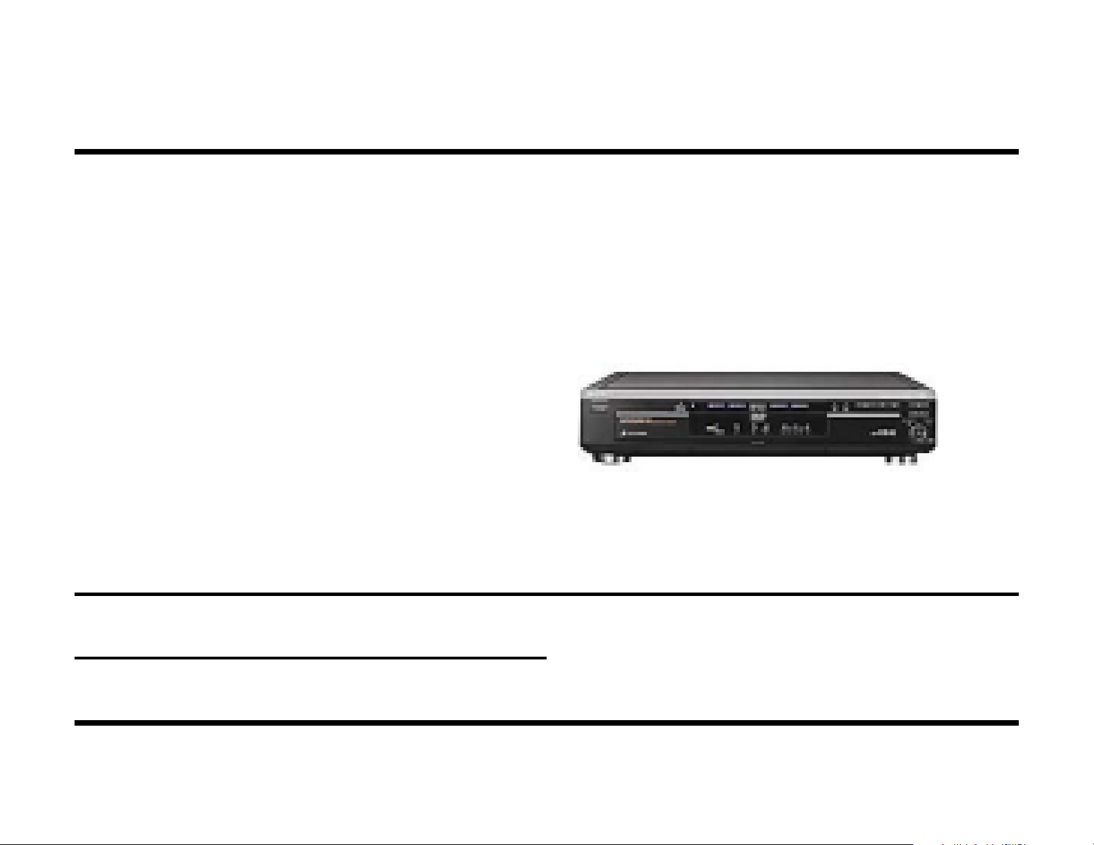
Digital Video Player
Sony DVD Players
Models: DVP-S300 DVP-S570d
DVP-S330 DVP-C600d
DVP-S350 DVP-C650d
DVP-S360 DVP-C660
DVP-S500d DVP-C670d
DVP-S530d DVP-S3000
DVP-S550d DVP-S7000
Training Manual
DVP-S560d DVP-S7700
Troubleshooting
Course: DVD-03
Page 2
g
Internal IC Numbers
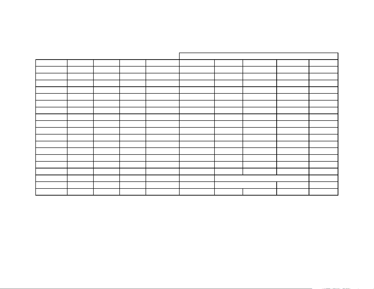
Model Gen Intro Year MSRP Optical RF Amp ARP A/V Decod A DSP Servo DSP
DVP S300 2 1997 $599.99 KHS180A SSI33P3720A CXD1865R L6402GQC27 MB86342PF CXD8730R
DVP S330 3 1999 $349.00 KHM220AAA SSI33P3722 CXD8784R CXD1930G none CXD8791Q
DVP S350 4 2000 $ KHM220AAA SSI33P3722 CXD9576R CXD1932Q none CXD9569R
DVP S360 4 2000 $299.00 KHM220AAA SSI33P3722 CXD9576R CXD1932Q none CXD9569R
DVP S500d 2 1997 $599.99 KHS180A SSI33P3720A CXD1865R L6402GQC27 MB86342PF CXD8730R
DVP S530d 3 1999 $499.00 KHM220AAA SSI33P3722 CXD8784R CXD1930G CXD1901R CXD8791Q
DVP S550d 3 1999 $599.00 KHM220AAA SSI33P3722 CXD8784R CXD1930G CXD1901R CXD8791Q
DVP S560d 4 2000 $399.00 KHM220AAA SSI33P3722 CXD9576R CXD1932Q CXD1939R CXD9569R
DVP S570d 4 2000 $599.00 KHM220AAA SSI33P3722 CXD9576R CXD1932Q CXD1939R CXD9569R
DVP C600d 2 1998 $699.00 KHS180A SSI33P3720A CXD1865R L6402GQC27 MB86342PF CXD8730R
DVP C650d 3 1999 $599.00 KHM220AAA SSI33P3722 CXD8784R CXD1930BQ CXD1901R CXD8791Q
DVP C660 4 2000 $449.00 KHM220AAA SSI33P3722 CXD9576R CXD1932Q CXD1939R CXD9569R
DVP C670d 4 2000 $549.00 KHM220AAA SSI33P3722 CXD9576R CXD1932Q CXD1939R CXD9569R
DVP S3000 1 1997 $699.00 KHS180A SSI33P3720A discrete ICs CXD2545Q
DVP S7000 1 1996 $999.00 KHS180A SSI33P3720A discrete ICs none CXD2545Q
DVP S7700 2 1998 $999.00 KHS180A SSI33P3720A CXD1865R L6402GQC27 none CXD8730R
Gen = Generation based upon internal ICs used.
MSRP = Manufacturer’s Suggested Retail Price (List price)
ARP = Advanced RF Processor (analog input, separate digital DVD & CD process, spindle motor control)
A/V Decod = (MPEG) Audio/Video Decoder
A DSP = Audio Digital Sound Processor (Dolby AC-3 decoding)
Servo DSP = Focus, Trackin
, Sled Digital Servo Processor
Page 3

Table of Contents
How to Use This Book 2
Modern Soldering Techniques 3
IC Removal - Which Method? 3
IC Installation 7
First Generation DVD Players
Symptom 1 - Intermittent loss of brighness during PB 11
Symptom 2 - No color or color change hue 13
Symptom 3 - No DVD disc detected at start up. CD PB OK 17
Symptom 4 - Intermittent or distorted DVD audio 19
Symptom 5 - No PB or picture freeze on some dual layer discs 21
Second Generation DVD Players
Symptom 1 - No response to the Power ON button 23
Symptom 2 - Powers OFF two seconds after turn ON 27
Symptom 3 - Plays CD, but not DVD discs 31
Symptom 4 - No PB. Disc stops spinning 33
Symptom 5 - One color, picture distortion or dark screen 35
Third Generation DVD Players
Symptom 1 - Green Power light does not stay ON 37
Chip Select Waveforms 47
Symptom 2 - Audio distortion after warm-up 49
Symptom 4 - Unit powers OFF during PB or if left ON 53
Symptom 5 - Picture freezes or powers OFF trying to PB
dual layer discs 55
Symptom 6 - DVD-C650 only - Powers ON, but no buttons
work. Error code E27 displayed 57
Symptom 7 - DVP-C650 only - Tray does not rotate 59
Symptom 8 - Tray does not Eject. Displays “LOCKED” 60
Fourth Generation DVD Players
Symptom 1 - No PB. Display = “No disc” or “C:13:00” 61
Symptom 2 - Powers OFF after powering ON 63
Symptom 3 - The tray open button has no effect 63
Symptom 4 - No chroma from the S video output jack 65
Symptom 5 - Digital picture blocks during the movie 69
Symptom 6 - Tray does not Eject. Displays “LOCKED” 70
Test Mode - Third Generation 71
Test Mode Access 71
Tests 71
Appendix
Service Bulletin List i
Service Bulletins iii
Symptom 3 - Spindle motor rotates immediately at Power
ON. No tray open 51
Page 4

1
NOTES
Page 5

How to Use This Book
Purpose
DVD players and camcorders have moved into the digital age where signal routing is less important than IC communications. You can learn a
little about how ICs communicate and add to your service strategy for
DVD player repairs by examining previous DVD player failures that have
occurred across the USA.
Book Structure
This book is organized into five sections:
Common Symptoms for DVD Players
DVD repairs across the USA were examined and repetitive symptoms
were extracted. For each common symptom, a strategy was developed
to determine which part has failed. This was done to each of the four
generations of DVD players.
Service Bulletins
The first page in this group contains a list of the DVD bulletins, a description of each bulletin, and the models to which the bulletin pertains. This
list is followed by the DVD service bulletins to date.
1. List of DVD Models categorized into generations
2. Table of Contents
3. Modern Soldering Methods
4. Common Symptoms for Sony DVD Players:
First Generation
Second Generation
Third Generation
Fourth Generation
5. Service Bulletins
List of DVD Models categorized into generations
Locate the DVD player you are working on in the chart and note the generation it falls in.
Modern Soldering Methods
Even though the technician has identified the defective part, the repair
cannot be completed unless the old part is removed without damaging the
board and the new part installed without solder bridges. This skill can
only be acquired by following all the steps that other technicians have
mastered.
Using this Book
1. Go to the “DVD Model List” before the Table of Contents.
2. From the DVD Model List, find your DVD model and note the generation it falls under.
3. Return to the Table of Contents to find the first, second, third or fourth
generation heading that corresponds to your DVD player.
4. Match the symptoms of your DVD player to the ones listed.
5. Go to the corresponding page for the troubleshooting information.
Mechanical problems like broken gears are not listed.
If your symptom is not listed, you do not have a common problem.
2
Page 6
Modern Soldering Techniques
This section is an excerpt from the Sony videotape (p/n T-MODSOL-9) by
the same name. This document only shows how to remove and install
multi-pin ICs used on many Sony products. The removal of these fine
lead large-scale integrated circuits (LSI) requires modern methods. After
replacing the IC, checking each pin for solder bridges is essential to prevent IC damage.
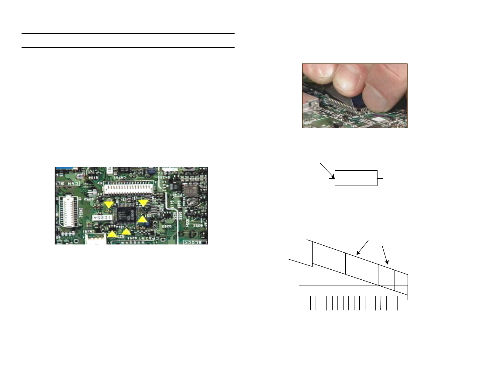
IC Removal - Which method?
Choose one of three methods for removing the ICs based upon the density of parts about the defective IC.
3
Use a sharp knife blade each time you remove an IC because the knife
was not originally intended to cut metal. Break off the old blade segments
of knife before cutting to expose a new sharp blade.
Cutting the IC’s leads in a high-density board is the best method for IC
removal. If there are many small parts about the defective IC the hot air
and Chip Quick removal methods may desolder local components. If you
choose the chip quick method, keep solder to a minimum on the IC pins.
Use the CUT OUT IC removal method when there
are many parts surrounding the IC
IC Removal - Cut Out method
This method requires a minimum of tools to cut the legs off the IC and
clean the board:
• Knife
• cutters
• dental pick
• soldering iron
• solder wick
1. You must place the new blade at the legs where they meet the IC
body. Angle the blade into the body slightly to avoid slipping off the IC
legs.
2. Along the IC legs, hold the knife at a shallow 20 - 30 degree angle.
3. Place your finger above the blade for control as you press down and
rock the blade down.
20-30 degrees
Blade
IC
IC
Page 7
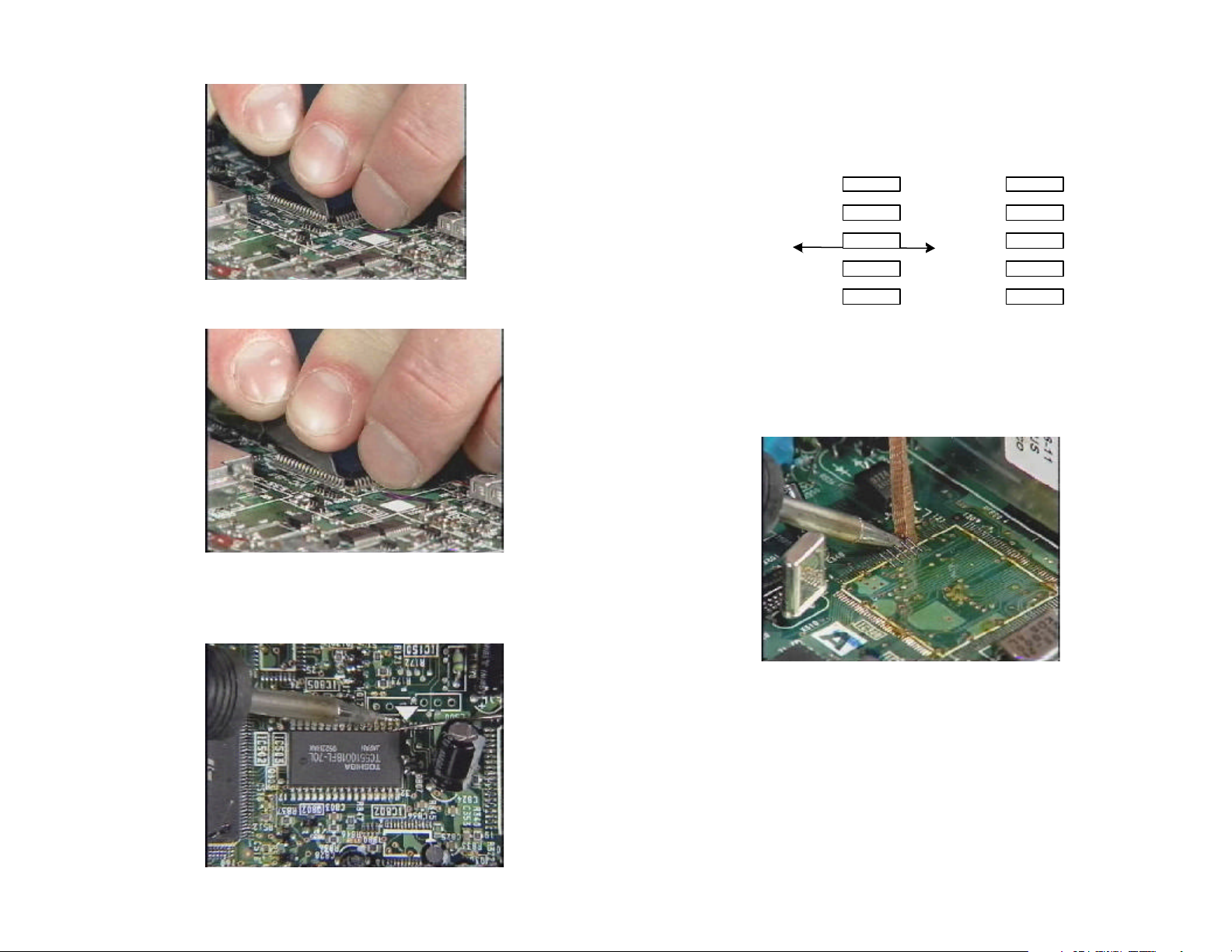
4. You should apply enough pressure to shear off 4-5 legs as you rock
the blade while pressing down. DO NOT let the blade point touch the
board.
6. Use a standard soldering iron to heat and push the legs off the lands.
Push only in the direction of the lands so they are not damaged.
Wipe across
the land
IC Lands
7. Remove the solder on the lands using a solder wick looped about the
soldering iron for better control.
5. Reposition the blade back along the legs and repeat. Do not cut the
last leg off or you will lose control and the blade point will hit the board.
Use cutters to nip these last IC legs or unsolder and lift the leg with a
dental pick. Remove the IC body.
4
Page 8
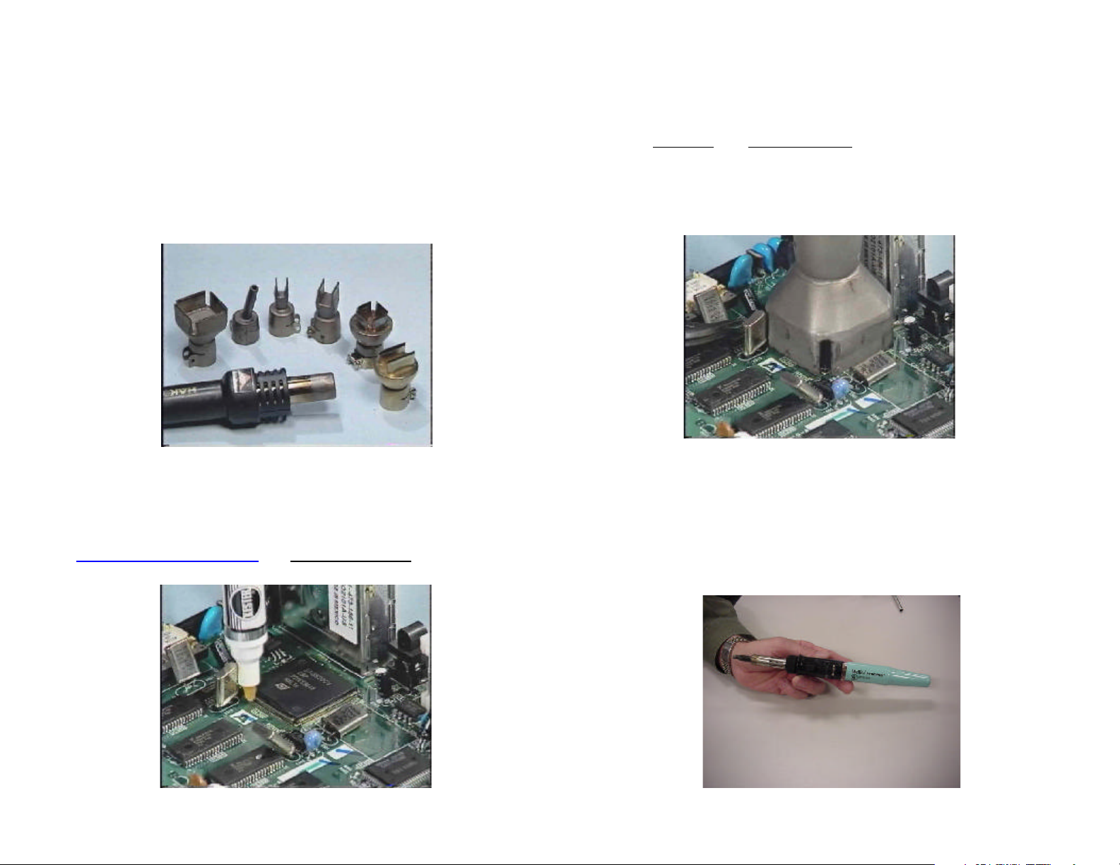
IC Removal - Hot Air method
This method requires the following:
• Hot Air Controller
• Desoldering Tips
• Flux Pen
• Tweezers
In the following steps you will use the Hot Air Controller to heat up all the
pins while you lift the IC off the board with tweezers.
5
2. If you cannot find a hot air tip that will cover the IC, attach a single
1/8” (0.125”) diameter tip that will heat all the pins if you move the tip
around the IC pins.
3. Start at 0 air flow and maximum heat so the tip will warm up fast.
4. After warm up increase the air flow slightly (to #1 of 10) and position
the hot air tip over the pins of the IC. Do not touch the IC with the tip.
Count the nearby components and make sure they do not move away
by controlling the airflow. Insert tweezers at the corner of the IC.
1. Apply flux from a pen to remove the oxide layer from the IC pins during heating. Removing the oxide establishes a uniform temperature
on all the IC pins for removal and prevents an IC leg from still being
attached to the land when lifting the IC. These low residue pens are
made by Kester and distributed by companies such as
www.mcmelectronics.com and www.newark.com.
5. Gently lift the IC with the tweezers.
6. Remove the solder on the lands using a solder wick looped about the
soldering iron for better control.
IC Removal - Hot Air method using butane torch
The hot air controller is effective, but expensive. The butane torch is
similar in performance and inexpensive (about $100). In Weller’s PyroPen,
hot air comes from a controlled flame.
Page 9
Put safety goggles on before using the butane torch. Circle the IC leads
with the torch flame and flip the IC over when the IC is loose.
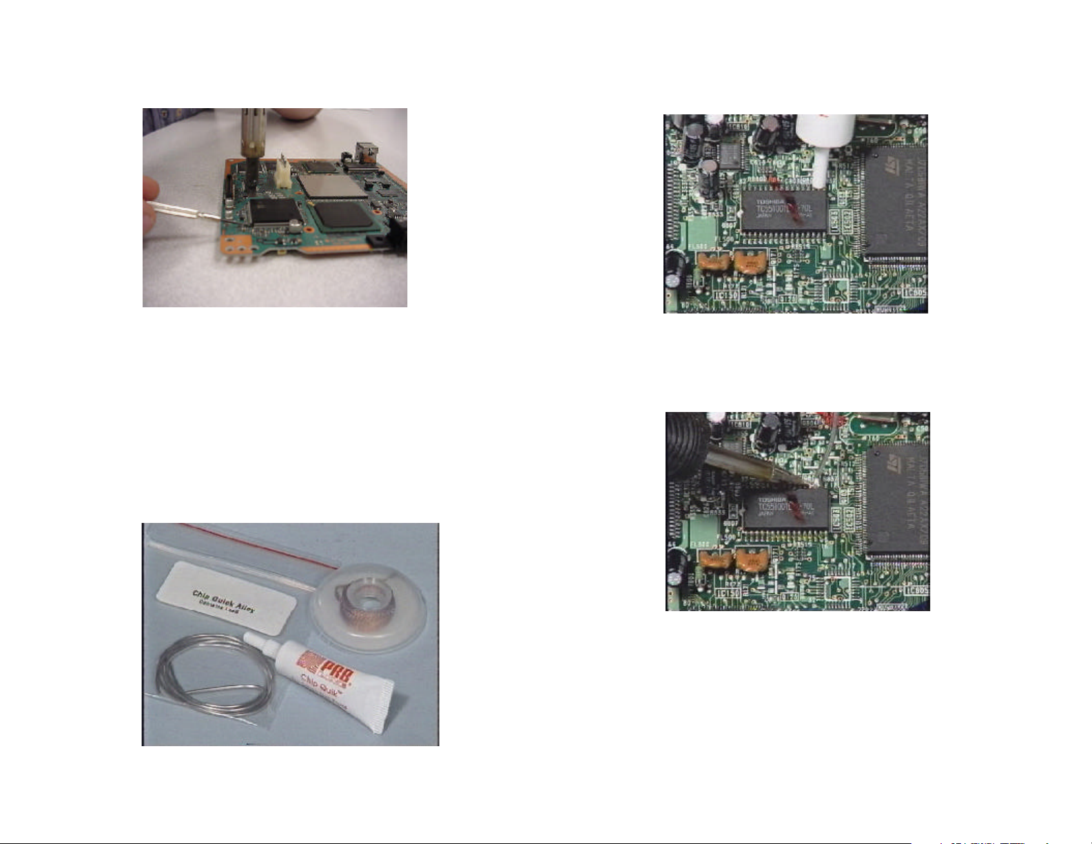
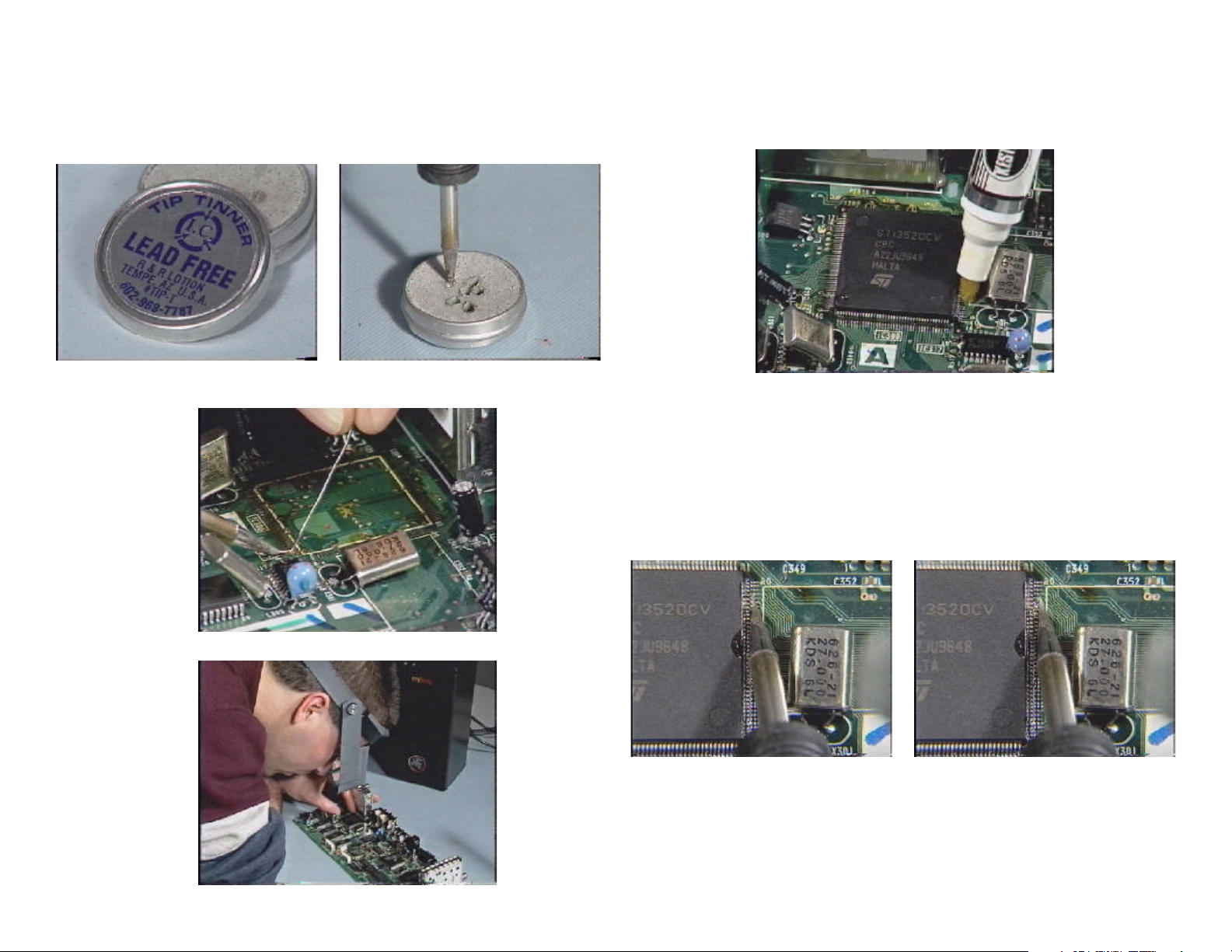
IC Removal - Chip Quick Method
Chip Quick is a low temperature solder that remains molten longer than
ordinary solder, giving you time to unsolder the IC. Chip Quick is best for
removing medium to large scale ICs when there are few parts about the
IC. This method takes about the same time as the hot air method and
requires about the same level of skill.
The Chip Quick package (P/N = T99856421) contains:
• Low Temperature Solder
• Flux
• Wick
1. Apply the Chip Quick flux to all the leads of the IC. (Medium size IC
shown for removal).
2. Melt the Chip Quick solder along the IC leads. Keep the solder molten
by running your iron along the IC leads.
3. Insert tweezers and lift the IC up.
6
Page 10
4. Remove the blobs of Chip Quick by heating and removing with a solder
sucker.
7
IC Installation
Once the solder and bridges are cleaned off with a solder wick, the new
IC can be installed. You must prevent static charges from damaging the
new IC by using a grounded wrist strap. The amount of static electric you
generate depends upon the humidity level and the clothing worn that day.
Some days you will not generate enough static electricity to damage the
new IC.
To solder all the IC leads without creating bridges, you need a constant tip
temperature soldering iron.
5. The remaining Chip Quick is removed with a solder wick. Move the
wick in the same direction as the lands of foil.
The constant tip temperature makes soldering uniform and increases the
speed of the soldering so you don’t have to resolder missed leads. Since
these constant tip temperature irons have a 5-10 second warm-up time
there is no reason to leave these irons on when in use.
Page 11
1. Whichever iron you use, clean the tip by dipping it into a cleaner or
tinner. Kester and Multicore manufacture these. A dirty tip will cause
you to mis-solder some IC leads as you drag the solder across the IC
pins.
2. Tin one land on the board, then position the IC over the lands.
3. With the IC in place solder the lead to the tined land.
5. Apply flux from a pen to all the IC leads to stop solder bridges.
6. Using the magnifying glass, place the iron’s tip furthest away from you
on the IC pins and apply enough solder for 10 lands. Using the flat
part of the iron, drag the solder blob down the pins in a side by side
motion (zigzag pattern) allowing the solder blob to touch (heat) each
IC lead and land. Only a small amount of solder resides at each land.
At first it looks at though the lead was not soldered.
4. Check the IC position and solder another lead to hold the IC in place.
8
Page 12
7. After soldering all the pins, run a dental pick across the pins to see if
movement reveals an unsoldered one.
8. Most technicians forget to inspect for bridges after installing the IC.
When power is turned ON, a bridge will take out the new IC or damage another related parts. Therefore it is important to inspect the pins
for bridges before approving your own work.
9
10. Remove the excess flux by spraying the area lightly with flux remover.
9. Using a low flux solder means you do not have to clean the board of
flux with a flux remover…
11. Place a towel over the work and dab the flux off with the stiff bristles of
the brush. This leaves the work clean without the cotton fibers leftover
had you used a cotton swab.
Sony is a registered trademark of Sony.
Chip Quick is a registered trademark of Chip Quick Inc; Mashpee, Mass.
Page 13

NOTES
10
Page 14

First Generation DVD
The first generation Sony DVD player consisted of two models, the DVPS3000 and the DVP-S7000. They housed separate laser assemblies to
play DVDs and CDs. Much of the video processing was done by discrete
medium size ICs. Failures across the country have been very low so
there is not much feedback history.
Symptom 1: Intermittent loss of brightness in the picture during PB
Cause: 1. Broken Video jack solder connection
2. A/V Decoder IC281 broke solder connection
3. A/V Decoder IC281 defective.
11
Repair Procedure
1. Check both video jacks for broken solder connections.
2. Press down on IC281 when the intermittent occurs. Resolder all the
pins if the condition responds to movement. Use flux on the pins to
prevent solder bridges and inspect the pins before powering the unit
on.
3. If the problem appears thermal, cool off the IC to see if the brightness
returns. Replace IC281.
Page 15
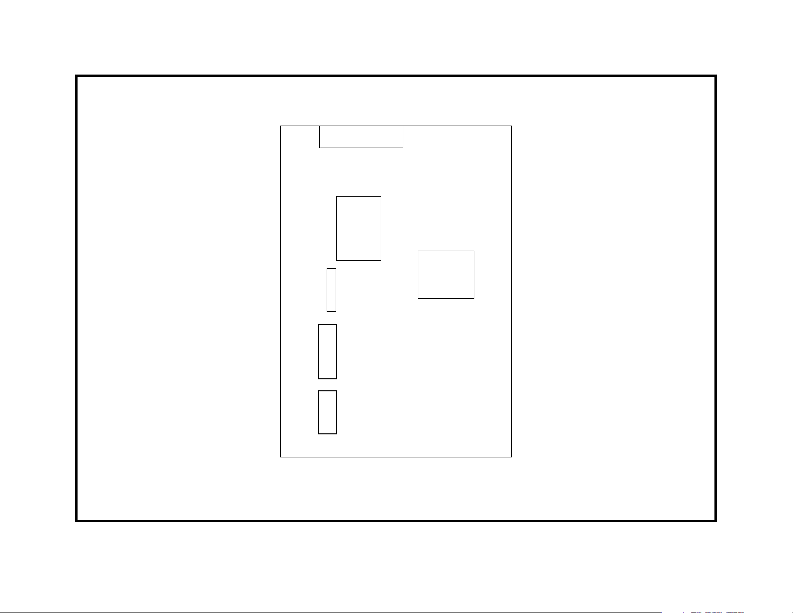
MB - 75 Board
Shield
X001
X002
IC002
X003
X280
R213
A/V
Decoder
IC281
1ST GENERATION - A/V DECODER / XTAL LOCATION SYMPTOM 1, 2
12
12/7/00
Page 16

First Generation DVD
The first generation Sony DVD player consisted of two models, the DVPS3000 and the DVP-S7000.
Symptom 2: No color or colors changing in the picture.
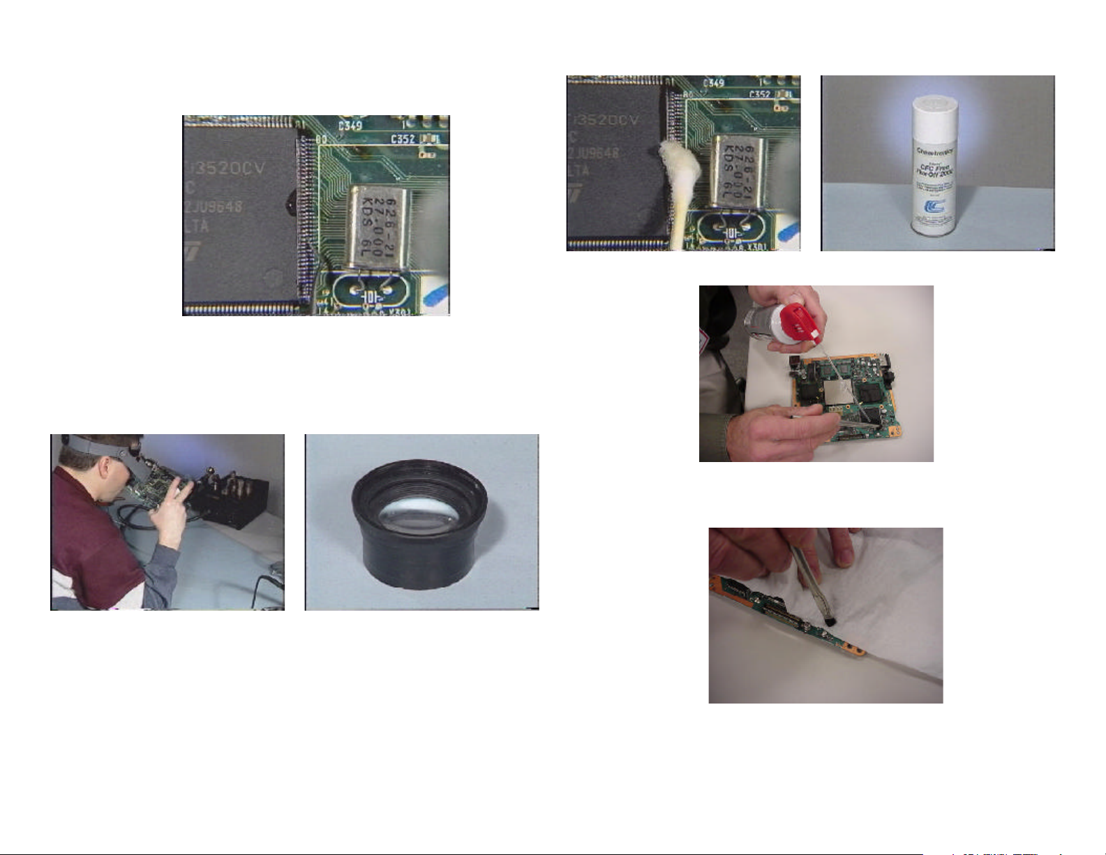
Cause: 1. X280 (66MHz) crystal near IC281 on the main board.
2. X003 (27MHz) crystal in the “can” on the main board.
Repair procedure
1. Turn the unit ON. The Xtals will start immediately. Check the 66MHz.
crystal by placing a scope and frequency counter (using a X10 probe)
on the crystal (corner nearest IC281) or on either side of R213 that is
in series with the Xtal. If the signal is off frequency or below 0.9Vp-p,
replace the crystal.
2. Perform the 27MHz free run adjustment by grounding TP025 and setting RV001 for 27MHz
+100Hz at TP018.
13
Page 17
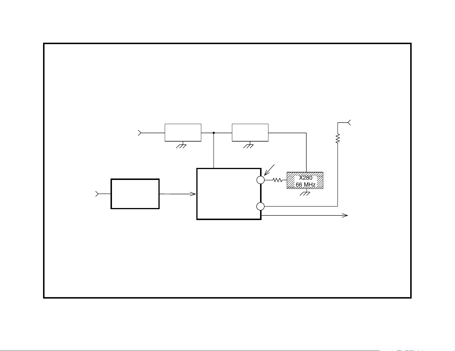
DECRYPT
IC184
3.3V
BUFFER
CONTROL
IC217
FL281 FL282
MPEG
VIDEO
DECODER
IC281
117
87
1V p-p
1.8Vdc
R213
220
X280
66 MHz
27 MHz
PLL IC002/16
R216
22
LETTERBOX
IC310
1ST GENERATION - 66 MHz XTAL SYMPTOM 2
14
12/28/0021DVD03
Page 18

15
D001
-5V
LPF
IC006
X003
27 MHz
27 MHz
FREE RUN
R027
100K
RV001
18
19
21
PLL
IC002
42
TP025
SHIELD ON
MB-78 BOARD
X003
16
4.7Vdc
MB-78 BOARD
R022
22
27 MHz
BUFF
IC012
RV001
27MHz
IC002
FL012
FL036
FL037
TP025
TP018
27MHz
TP018
MPEG AUDIO DEC IC381/27
VIDEO DECODER IC281/87
VIDEO ENCODER IC475/8
LETTER BOX IC310/91
SUB PIX IC312/123
VIDEO EQ IC317/89
DATA PROCESS IC181/3
DECRYPT IC184/21, 43
BUFF CONTROL IC217/24
27MHZ ADJ
1) GND TP025
2) ADJ. RV001
FOR 27MHz + 100HZ
AT TP018
1ST GENERATION - 27 MHz DISTRIBUTION SYMPTOM 2
22DVD03
1/8/01
Page 19

NOTES
16
Page 20

First Generation DVD
The first generation Sony DVD player consisted of two models, the DVPS3000 and the DVP-S7000.
Symptom 3: No DVD disc detected at start up. CDs
may PB OK.
Cause: Laser assembly or Spindle motor is at end of its life.
Repair procedure
You will check the DVD RF level and use that to determine if the laser
output is sufficient to play back DVDs.
1. Check the DVD laser output at CN760/pin 1 on the MB board. Although there may not be an eye pattern because the DVD only starts
to play, you should see RF at CN760/pin 1. Normally there is a 1.6Vpp eye pattern at CN760/pin 1. The minimum operating RF level is
0.9Vp-p. The CD RF test point is at a different location.
17
2. If the DVD RF level is above 0.9Vp-p, suspect the spindle motor. Even
though the DVD disc spins, replace the spindle motor (P/N = 1-698944-11). Often when the spindle motor is bad, the RF eye pattern is
not clear or the waveform squeezes and expands like a musical accordion before shutting down.
Page 21
CN980
MB-78 BOARDTT-701 BOARD
CN760
21
BOARD
LAYOUT
DVD
RF
2
22
27 mVp-p
CN980
12
34
MB-78 BOARD
12
34
5
TP891
CN886
IC765
AMP
CN760
2
1
IC770
RF
1.6Vp-p
RF PROCESS
IC770
1ST GENERATION - RF CHECK POINTS SYMPTOM 3/5
18
23DVD03
1/3/01
Page 22

First Generation DVD
The first generation Sony DVD player consisted of two models, the DVPS3000 and the DVP-S7000.
Symptom 4: Intermittent or distorted sound when playing DVD movies only (not CDs).
Cause: Audio Control IC380 is defective.
Repair Procedure
1. Replace IC380 CXD8603BR (P/N = 8-759-490-29).
19
Page 23

RF
TT-701
BD
RF
PROCESS
IC770
DATA
PROCESS
IC181
DECRYPT
IC184
BUFFER
CONT
IC217
AUDIO
AUDIO
CONTROL
CONTROL
IC380
IC380
DECODER
MPEG
AUDIO
DECODER
IC381
MPEG
VIDEO
LETTER
BOX
IC310
DIG
FILTER
IC801
IC312
D/A
CONV
IC802
SUB
PIX
NTSC
VID
ENCODER
IC475
AUDIO
OUT
VIDEO
OUT
1ST GENERATION - A/V PROCESS SYMPTOM 4
20
24DVD03
12/28/00
Page 24

First Generation DVD
The first generation Sony DVD player consisted of two models, the DVPS3000 and the DVP-S7000.
Symptom 5: No PB or Picture freezes when playing
parts on some dual layer (gold) discs.
Cause: 1. Laser getting weak.
2. ROM IC093 cannot PB marginal spec gold discs.
Repair procedure
You will measure the DVD RF level going to the servo (not video) stages
and use that level for making the laser performance judgement.
1. See service bulletin 47 to locate TP891 (same as CN886/pin 5). Less
than 0.95Vp-p means you should replace the optical assembly. Align
the unit for all three disc types (CD, DVD single and dual layer).
2. If the RF level is normal at approximately 1.5Vp-p, replace ROM IC093
as in service bulletin 43R2 depending upon the model.
21
Alignment after laser replacement
The Tilt, focus, and Tracking adjustments are performed automatically
from the test mode using the remote and test discs. After the test mode is
accessed and “drive automatic adjustment” is entered, you are prompted
to load the first DVD disc for alignment. Afterwards the screen prompts
you to replace the disc with a dual layer DVD and then finally with a CD to
complete the alignment. The procedure is as follows:
• Access the Test Mode by pressing the following buttons on the remote: Time, Clear, then Power.
• From the Test Mode Menu, select 1. Drive Auto Adjustment.
• From the Auto submenu, select 0. All (discs – one at a time).
• The screen will prompt you as to what disc to place on the tray and
what buttons to press to complete the alignment.
Page 25

NOTES
22
Page 26

Second Generation DVD
The second generation DVD players consist of models DVP-S300, DVPS500d, DVP-C600d, and DVP-S7700.
Symptom 1: No response to the Power ON button.
23
your unit from responding to the Power ON button. This is because
the front panel must be removed to reseat the encoder cable and it is
more important that you locate the problem. Either use your ohm
meter to locate a short at the power supply connector CN201 or repeatedly press the power button while monitoring the output voltages
to see which one is missing:
CN201/pin 1 = +5.2Vdc
Cause: There are three common causes for this symptom.
1. A damaged power supply;
2. A short on another board that causes no power supply output voltage;
or
3. A defective front panel encoder (ref #165 in the DVP-S500d service
manual) preventing IC604 from reading the power ON button by locking up its program so the unit may not turn ON (intermittent turn ON).
Repair Procedure:
The power supply runs all the time when 120VAC is input, producing E
+5V. The +3.3V, +5V and
turned ON. You first need to determine if the basic power supply is defective.
1. Unplug the cable from the only connector on the power supply, CN201.
Look for E+5Vdc at CN201/pin 6 (alternate test point is at PS312)
from the power supply board. If there is no voltage, the power supply
is inoperative. The most common cause is a shorted main oscillator
MOSFET transistor, Q103, which has taken out the main fuse. Q103
P/N = 9-880-437-01 which is a 2SK2798 for the USA models.
If the new Q103 fails or there is still no output voltage, replace the
associated control parts Q101, Q102 and D104.
+12V outputs are switched ON when the unit is
CN201/pin 2 = +5.2Vdc
CN201/pin 3 = Ground
CN201/pin 4 = +3.3Vdc
CN201/pin 5 = Ground
CN201/pin 6 = E5.Vdc
CN201/pin 7 = Ground
CN201/pin 8 = P Cont (input)
CN201/pin 9 = AU +12Vdc
CN201/pin 10 = AU Ground
CN201/pin 11 = AU –12Vdc
CN201/pin 12 = -12Vdc
CN201/pin 13 = Ground
CN201/pin 14 = Motor +12Vdc
CN201/pin 12 = Motor Ground
Use the +3.3V and 5V distribution diagrams in this book (symptom 2) to
locate the shorted IC.
2. If the power supply does produce the E+5, the front panel rotary encoder or a short in another board is suspected. The encoder is attached to a ribbon cable that plugs into CN103 of the front panel board.
Unplug the encoder, plug in the power supply cable and press the
power ON button to verify the defect.
3. If the unit still did not power up, you may leave the rotary encoder
cable detached while you look for the short circuit that is preventing
Page 27
Q103 OSC.
2SK2178
T101
D211
D211
Q211 SW.
2SJ488
P211
P312
CN201
14
MTR+12V
11
AV+12V
6
E+5V
Q101
2SK2798
HS-930 SU
BOARD
2ND GENERATION - POWER SUPPLY SYMPTOM 1
D104
2.4V
Q102
2SC2377
D611
Q312
INV.
IC611
3.3V REG.
Q311 SW.
2SA1679
P311
Q511,
Q512
SWITCH
P CONT.
P511
2
1
+5.2V
8
P CONT.
4
3.3V
11
AV-12V
12
-12V
4DVD03 1294
1/8/01
24
Page 28
25
FL88 BD.
POWER
ROTARY
ENCODER
JOG WHEEL
ENTER
BUTTON
P/N 1-475-685-11
CN103
MB78 BD.
IC604
IF MICON
HS930 SW BD.
POWER SUPPLY
P CONT.
IC611,Q311,
Q211
EVER
5V
2ND GENERATION - POWER ON SYMPTOM 1
18DVD03 1307
1/16/01
Page 29

NOTES
26
Page 30
Second Generation DVD
The second generation DVD players consist of models DVP-S300, DVPS500d, DVP-C600d and DVP-S7700.
Symptom 2: Powers OFF two seconds after turn ON
Cause: There are two causes for this symptom –
1. An internal IC short will load down a power supply voltage. This removes the voltages to the other ICs and communications end. Once
IC communications end, Syscon shuts down the DVD player because
it senses a defect.
2. At power ON the laser must be detected at home position or the unit
will detect a malfunction and shut down. If the sled motor is frozen,
the laser will not return to home.
Repair Procedure:
If the power supply board makes a chirping noise when you press the
power button, an output is being loaded down. Measure the output voltages to find out which one. The most common shorted ICs are:
27
If the power supply is OK, the sled may be defective on these older units.
Remove the lid that houses the mechanism and slide the laser away from
home at the spindle motor. At power ON, the laser should travel to the
spindle motor (home) then move outward. If home is not detected, the
laser assembly will incorrectly remain where it is and the unit will shut
down. The sled motor assembly is P/N = X-394-713-71.
2nd Generation Players - Shorted ICs
Function IC # Ref # in DVP-S500d
Large Gate Array (LGA) CX8728Q IC804
Audio DSP CX8730R IC506
Page 31

FL201
IC201, IC202
+3.3V
INTO
FL202
FL006
IC203
CN001/5
FL805
FL101
IC806, IC810
IC104, IC105, IC101
2ND GENERATION - MB-78 BD. -3.3V DISTRIBUTION (DVP-S500D)
7DVD03 1297
11/30/00
28
Page 32

29
+5.2V
INTO
CN001/7,8
F005
1.6A
F006
1.6A
FL003
FL007
FL007
FL005
FL001
FL008
D 5V
S 5V
A 5V
AU 5V
DP 5V
FL801
FL802
FL803
FL807
FL804
FL501
FL502
FL808
FL254
FL208
IC804
IC807
IC811
IC805, IC803
IC806
CN601/2 (FL-88 BD.)
OP AMPS: IC452, IC502,IC507
IC506, CN501 (CHECK)
IC506
IC806
CN252/9 (AU197 BD.)
IC252
CN252/25 (AU197 BD.)
OP AMP IC205
FL211
FL212
FL251
FL252
PLL IC209
OSD IC207
IC251
IC252
CN203/10, CN252/4 (AU-197 BD.)
2ND GENERATION - MB-78 BD. +5V DISTRIBUTION (DVP-S500d)
5DVD03 1295
12/28/00
Page 33

IC207 IC202IC201
CN252
F808
FL502
FL202
IC811
IC363
FL807
FL001
FL007
FL006
FL803
IC807
FL005
FL003
FL008
CN001 CN002
FL201
IC203
FL802
FL251
IC252
FL212
FL254
IC251 IC252
MB-78
BOARD
FL805
CN101
IC802
IC803
IC810
FL801
FL208
IC209
FL211
IC608
IC105IC101
FL101
CN251
TOP BOTTOM
2ND GENERATION - "FL" FILTER LOCATIONS
IC805
IC804
IC604
CN702
IC506
CN701
IC806
IC104
CN601
6DVD03 1296
1/8/01
30
Page 34

Second Generation DVD
The second generation DVD players consist of models DVP-S300, DVPS500d, DVP-C600d and DVP-S7700.
Symptom 3: Plays CD but not DVD discs
Cause: There are three common reasons that the player will only PB CDs:
1. The laser beam must be perpendicular to the disc. This is critical
when reading fine pitched DVD discs, but not for CDs. Therefore if
the tilt servo is not working, CDs will still play but not DVDs. Inspect
the Laser base unit for a crack in the plastic preventing tilt.
2. The laser assembly may have low output. As the laser output decreases with use, the RF eye pattern decreases in amplitude causing
skipping, and finally no DVD playback.
3. The spindle motor must turn faster when playing a DVD. As the motor
brushes wear down, the torque at the high speed cannot be maintained and the DVD does not reach the normal operating speed.
4. Corrupt EEProm data.
Repair procedure
1. Inspect the plastic base unit holder (DVP-S500d ref. #263) for cracks
that prevent the laser assembly from tilting.
You can also operate the tilt mechanism from the test mode under
section “Manual Adjust 2” for inspection. With the player OFF, press
the remote control TITLE, CLEAR, and then the POWER button to
enter the test mode. Using the number buttons, select
Operation, 5 Manual Adjust, then 2 Tilt Offset. After remembering the
original offset number, use the arrow buttons to change the offset
number and drive the tilt motor. As the motor turns, the laser assembly should be mechanically tilting. Return to the original offset number
before exiting (exit by pressing the power off button).
2 Drive Manual
31
detected when the RF level drops lower than 0.9Vp-p. Even when no
disc is detected at slightly below 0.9Vp-p, a DVD may still play in the
test mode, producing only a low amplitude eye pattern. No picture
appears when the servos are individually (manually) turned on for PB
in the test mode. See the Test Mode section of this book for further
information.
3. If the laser assembly tilts and the RF starts at 1Vp-p (minimum) before shutdown, the spindle motor could be worn. Replace the spindle
motor if the RF signal is above 1Vp-p (laser is OK). Sometimes a
defective spindle motor shows up in the test mode when the unit incorrectly identifies a 12cm DVD as an 8cm disc when attempting to do
the DVD drive adjustments. Enter the test mode and select
Manual Operation, 0 Disc Type, and 5 Disc Type Check.
4. The EEProm data may be defective but can be reset to default user
and service values from the Test Mode. After the default values are
entered, the player must be aligned. The procedure for resetting the
EEProm is as follows:
• Access the Test Mode by pressing Title, Clear, then Power buttons.
• From the Test Mode Menu, press 2. Drive Manual Operation
• From this sub menu select 7. Check for the memory access.
• Select 1. EEProm Default Set
• Press RETURN several times to go back to the initial Test Mode Menu
to begin automatic alignment.
• Select 1. Drive Auto Adjustment and follow the directions to adjust tilt,
focus and tracking sections.
: 2 Drive
2. On the MB-78 board monitor, check connector CN303/pin 1 for a RF
(eye pattern) signal when trying to play a DVD. The normal signal
level here is 1.2Vp-p. As the laser ages, this level decreases. Skipping occurs when the level drops to approximately 0.9Vp-p. No disc is
Page 35

2ND GENERATION - OPTICAL ASSEMBLY SYMPTOM 3
32
1/3/0119DVD03
Page 36

Second Generation DVD
The second generation DVD players consist of models DVP-S300, DVPS500d, DVP-C600d and DVP-S7700.
Symptom 4: No playback -
• Disc stops spinning, DVD logo on screen; or
• Disc stops spinning, Dark screen (no video), no
initial DVD picture logo, no sound.
Cause: There are two common causes for this no PB symptom -
1. ARP (IC806 in DVP-S500d) CXD1865R defective or
2. A/V Decoder (IC203 in DVP-S500d) L64020-D-QC-27 defective.
33
Repair procedure
1. Insert DVD and monitor the RF test point on the MB board (CN303/
pin 1). If there is a clear eye pattern at start up, the ARP IC806 must
be OK to support the servo system that produces this eye pattern.
The A/V decoder must be causing the dark screen. Replace the A/V
decoder IC203.
2. If RF is present but NO eye pattern is obtained at the CN303/pin 1 test
point, the servos are not functioning. If the RF is at least 1Vp-p, suspect the ARP IC806.
Page 37

PATTERN
RF FROM
OPTICAL
ASSEMBLY
SLED FOCUS
TRACKING
SPINDLE
LOADING
DRIVERS
EYE
IC806
ARP
IC502
SERVO
DSP
IC811
DECRYPT
IC203
A/V
DECODER
IC252
VIDEO
DECODER
VIDEO
OUTPUT
2ND GENERATION - VIDEO PROCESS SYMPTOM 4/5
34
20DVD03 1302
1/8/01
Page 38

Second Generation DVD
The second generation DVD players consist of models DVP-S300, DVPS500d, DVP-C600d, and DVP-S7700.
Symptom 5: Multiple Symptoms -
1. Color / Picture distortion (after warm up):
• only yellow color;
• large digital blocks during playback
2. Dark screen - no DVD logo at power ON.
Cause: A/V decoder (IC203 in DVP-S500d) L64020-D-QC-27 defective.
Repair procedure
1. Replace A/V decoder (8-759-564-38).
35
Page 39

NOTES
36
Page 40

Third Generation DVD
The third generation DVD players consist of models DVP-S330, DVPS530, DVP-S550 and DVP-C650d.
37
one end and bringing it around to unsolder the remaining connections. Chip Quick
Although any IC can short, the more commonly shorted IC is IC701,
fed by B+ filter FL701.
does this best. Lift the hot filter off with tweezers.
Symptom 1: Green power light does not stay on.
Cause: There are three common causes for the unit returning to the
standby (power OFF) state. Follow the repair procedure to determine
which one is the cause.
1. A defect in the power supply causes a loss of power to one or more
ICs, resulting in no communications. When there are no communications, Syscon shuts down the player.
2. Similarly, if an IC in the unit shorts the power supply, there will also be
no communications and the unit will shut OFF.
3. Incomplete communications between an IC and Syscon is considered
a defect and shutdown is the protection.
Repair Procedure:
Either a short circuit or a communications failure in an IC is what is causing the problem.
Short Circuit
1. Check all the output voltages from the power supply. If all the voltages are present, go to “Communications Failure”.
2. If any voltages are 0V, unplug the MB-85 board to see if you can
isolate the short. The power supply will regulate unloaded.
3. A short on the +12 volt line means either IC801 or IC802 is defective
since they are the only ICs (on the MB85 board) that use +12V. Remove IC802 and if it is shorted, check the sled motor by applying a
3Vdc from an external power supply to see if it will run.
4. A short on the 3.3 volt line means any one of a number of ICs on the
MB-85 board is bad. 3.3 volts feeds each IC through a three connection inductive “FL” filter chip component. This is shown on the 3.3V
Distribution Diagram. Not all the ICs listed are used in every DVD
player. The FL filter can be removed by applying excessive solder to
Communications Failure
There is an initial communications between IC201, IC202 and IC205/6 at
power ON. Once these three ICs have talked, Syscon IC202 communicates with the remaining ICs on the serial and parallel bus. Syscon uses
chip select pulses to select an IC, communicate with it and repeats this
pattern with the next IC. Since the pattern is the same, we can use the
chip select signal to determine which IC is not communicating.
1. Resolder IC205/6 and recheck the unit for operation.
2. If the unit works when ON but doesn’t turn ON consistently when the
power button is pressed, perform S/B 62R1 to insure reliable reset of
three ICs on the MB board.
3. IC202 sends chip select pulses to ICs on the MB-82/85 board in the
order listed in the chart. If IC202 gets no acknowledgement from an
IC, the
down. Therefore if a chip select pulse is missing at power ON, the IC
before it on the chain is not acknowledging. Check each chip select
source at DVD power ON with a scope and determine which signal is
missing. Suspect the previous IC on the list. For example, if chip
select XCS (#6) was missing, the A/V decoder IC401 may be defective. Replace IC401.
1. CS 1 - IC202/pin 10 SRAM IC204 / HGA IC601
2. CE IC202/pin 11 Flash ROM IC205/6
3. CS 3 IC202/pin 8 AV Decoder IC401
4. CS 4 IC202/pin 7 HGA IC601
5. CS 2 IC202/pin 9 AV Decoder IC401
6. XCS IC601/pin 111 ARP2 IC303
7. HCS - IC601/pin 118 Servo IC701
next chip select pulse will not output and the unit will shut
Power ON IC check sequence
Chip Select Source Destination IC
Page 41

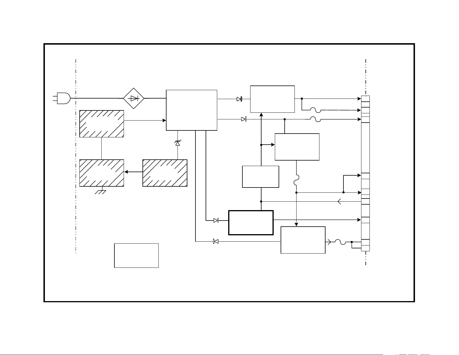
MECHANISM
OPTICAL
DEVICE
FOCUS
COIL
TRACK
COIL
TILT
M
SPINDLE CONTROL
IC802
RF
LD
IC001
AMP
TK-51 BD.
IC801
FOCUS
&
TRACKING
COIL TILT
MOTOR
FE
TE
PI
DRIVER
RF
RF
S.
DATA
CLK
IC304
DRAM
IC303
ARP2
DVD
DATA
CD
DATA,
CLK
IC401
AV
DECODER
PARALLEL BUS
Y,C
Y,P ,P
Y
SPDIF
ACHI-6,
CLK
IC403
IC403
SDRAM
b
r
IC501
AUDIO
DPS
AU212 BD.
S VIDEO
OUT
VIDEO
BUFFERS
COMPONENT
V OUT
COMPOSITE
V OUT
DIGITAL AUDIO OUT
IC902
DAC
IC905-7
DAC
5.1 CH
AC-3OUT
ANALOG
AUDIO
OUT
SPINDLE
M
SLED
M
LOADING
M
IC802
SPINDLE,
SLED &
LOADING
MOTOR
DRIVER
IC701
SERVO
SPINDLE
CONTROL
IC303
IC601
HGA
3.3V
POWER
BLOCK
FR150 BD.
BLOCK DIAGRAM
38
SYSTEM
CONTROL
MB-85 BD.
5V
12V
-12V
IC202
REC
IR
FLASH
P CONT.
IC205/
IC206
MEM.
IC201
INTERFACE
MICRO
IC204
SRAM
FL101 BD.
SERIAL BUS
IC201
EEPROM
DISPLAY
SWITCHES
13DVD03 1306
PANEL
12/28/00
Page 42

4. Sometimes when a chip select signal is missing, the IC it points to is
actually not defective. Usually a communications failure between IC202
and the remaining ICs on the serial or parallel bus is within the MB-82/
85 board. This could be caused by lack of power to non-communicating IC or it could just be defective.
Another possibility is that one of the programs in that IC cannot finish
because of a mechanical defect, so there is no acknowledgement
signal to complete the communications. For example, if IC701 is sending a sled drive move signal but the IC fails to receive a sled home
indication after a fixed time (“time out”), IC701 will not acknowledge
IC202.
39
Syscon IC202 will tell IC201 to shut down. In this failure example sled
driver IC802 is defective so the sled cannot move. Since IC701 is the
last chip in the chain, all the chip select signals are present. If the unit
shuts down with all the chip select pulses present, IC701 is not sending the final acknowledgment signal so the problem is at IC701 or its
slave ICs (IC801 or IC802). In this case, use the test mode to manually drive the focus, tracking and sled, tilt motors.
5. Inspect IC205/6 and check to see if this IC is one of the few units that
needs to be upgraded in the service bulletin # 61 for a 0.5-second lip
sync delay. This upgrade has no relation to the green to red power
light symptom.
Page 43

Green Power
Light Does Not
Stay On
Check All
Voltages
from Power
Supply
NG
Unplug Power
Supply Output
Cables
Measuring
Voltage at
P.S. Board
NG
Troubleshoot
P.S. Board
OK
OK
Communications
Failure
Short Circuit
on MB Board
Is Short on
+12V Line?
Is Short on
+5V or +3V
Line?
Yes
Yes
Did the Blue
Dolby Light
Come On?
Problem is
around
IC201, IC202,
IC205/6
IC801 or IC802
is Defective
Use +5V or
+3.3V
Distribution
Chart to Locate
Short
No
Yes
Support Remaining ICs on MB
Board. Follow Procedure to Locate
Missing chip Select Pulse.
Troubleshoot
Short on Other
Boards
3RD GENERATION - SYMPTOM 1 FLOW CHART
40
25DVD03
12/5/00
Page 44

SRV902
POWER
SUPPLY
BOARD
CN201
CN202
CN203
+3.3V
+5V +/-12V
EVER 5V
B301
3.3V,+5V,+12V
EVER 5V
-12V,
P CONT
41
AU208/212
AV010 BOARD
FR146/148/150
CONV BD.
FL97/99/101
DISPLAY BD.
CN001
MB-82/85
DIG PROC
BOARD
3RD GENERATION - POWER DISTRIBUTION
3DVD03 1293
11/30/00
Page 45

+12V
1 2 5 6 7
+5V
+3.3V
POWER
SUPPLY
CN202
FL501
FL503
7
1
CN001
FL301
18
1
CN003
IC401
(3.3V)
IC303
(3.3V)
IC701
(3.3V)
FL601
FL701
IC904
IC601
(3.3V)
IC202
(3.3V)
IC902
FL602
IC602
FL202
FL502
IC901
FL403
FL402
IC403
(3.3V)
IC402
(3.3V)
IC801
(+12V)
IC502
(3.3V)
FL404
FL014
FL002
FL401
FL303
FL005
IC304
(3.3V)
IC205/IC206
(3.3V)
FRONT
3RD GENERATION - 3.3V FILTER LOCATION
42
IC204
(3.3V)
FL204
FL205
BACK
IC802
(+12V)
2DVD03 1292
1/8/01
Page 46

43
+3.3V
INTO
CN001/6,7
GND
FL----
GND
FL104 FL404
FL104
OUTIN
FL401
FL403
FL402
FL701
FL005
FL202
FL204
FL205
FL301
FL303
FL601
IC401
IC401/161
IC403
IC402
IC701
CN003/9 TO TK-54 RF BD.
IC202
IC204
IC205/IC206
IC303
IC304
IC601
FL602
FL501
FL503
FL502
IC602
IC502
IC502
IC501
3RD GENERATION -3.3V DISTRIBUTION (MB-85 BOARD)
1DVD03 1291
11/30/00
Page 47

DOLBY
R285
EVER
5V
30 76
IC201
IF CON
POWER
71
CN201/
CN002
CN202/
CN006
SI
SO
POWER SUPPLY BD.
5
2
EVER 5V
CN001/
3.3V
CN202/
CN001
97
77
76
CN203
6 7
IC202
SYSCON
FR BD.
3
4
572
XIFCS
SO
SI
IC205/6
16 M FLASH
ROM
FL BD.
MB BD.
PARALLEL
BUS TO MEMORY
IM SRAM IC204
3RD GENERATION - INITIAL DATA COMMUNICATIONS SYMPTOM 1
44
9DVD03 1299
12/28/00
Page 48

45
CHIP
SELECTS
IC201
INTERFACE
CONTROL
CS
IC202
SYSTEM
CONTROL
SERIAL BUS
CS FROM
IC601
IC201
4k
EEPROM
CS FROM
IC202
IC205
FLASH
CS FROM
IC202
IC501
AUDIO
DSP
CS FROM
IC202
IC204
SRAM
CS FROM
IC202
IC902
AUDIO
2 CH
DAC
CS FROM
IC202
IC601
HGA
CS FROM
IC202
IC905
DAC
FRONT
CHIP
SELECTS
IC701
SERVO
CS FROM
IC601
IC906-7
DAC
REAR,
CENTER
CS FROM
IC601
PARALLEL BUS
TWO
CS FROM
IC202
PARALLEL BUS
IC401
AV
DECODE
IC303
ARP2
3RD GENERATION - SYMPTOM 1 - POWER OFF
CS FROM
IC601
12DVD 1301
12/1/00
Page 49

Power ON IC check sequence
IC401
IC601
IC202
81
120
1
35
Third Gen
MB board
Chip Select Source Destination IC
1. CS 1 - IC202/pin 10 SRAM IC204 / HGA IC601
2. CE IC202/pin 11 Flash ROM IC205/6
3. CS 3 IC202/pin 8 A/V Decoder IC401
4. CS 4 IC202/pin 7 HGA IC601
5. CS 2 IC202/pin 9 A/V Decoder IC401
6. XCS IC601/pin 111 ARP2 IC303
7. HCS - IC601/pin 118 Servo IC701
3rd Gen - Power ON Chip Select Sequence
46
Page 50

Chip Select Waveforms
All these chip select signals appear at power ON. The first five chip select signals also appear as long as the unit is ON. The last two only
appear at power ON and during the PB of a disc (or when the disc is
paused).
All waveforms are 3.3Vp-p taken at 10usec/div. time base.
CS 1 - IC202/pin 10 to SRAM IC204 / HGA IC601
47
CS 4 – IC202/pin 7 to HGA IC601
T
1
CH1!2.00 V= MTB10.0us- 1.16dv ch1-
CS 2 – IC202/pin 9 to A/V Decoder IC401
T
1
STOP
CH1!2.00 V= MTB10.0us- 1.16dv ch1-
CE – IC202/pin 11 to Flash ROM IC205/6
T
1
STOP
CH1!2.00 V= MTB10.0us- 1.16dv ch1-
CS 3 – IC202/pin 8 to A/V Decoder IC401
T
1
T
1
CH1!2.00 V= MTB10.0us- 1.16dv ch1-
These last two chip select signals only appear at power ON and during
disc PB.
T
1
CH1!2.00 V= MTB10.0us- 1.16dv ch1-
XCS – IC601/pin 111 to ARP2 IC303
HCS - IC601/pin 118 to Servo IC701
T
1
CH1!2.00 V= MTB10.0us- 1.16dv ch1-
CH1!2.00 V= MTB10.0us- 1.16dv ch1-
Page 51

3.3V
FL202
IC202
SYSCON
4 15 43 70 93
3.3V
14
5 4
IC207
POWER ON
RESET
# 2
# 2
R226
10k OPEN
*
R212 220 OHMS 0 OHMS
X3VRST
# 3
CN006
XFRRST
1
R257
100
3.3V
FRRST
1k 33 OHMS
8
IC201
IF CON
# 2
R252
*
77
P
CHECK
# 2 R251
1k 120 OHMS
*
FL601
XSDR
RST
IC601
HGA
114
R755
5.6k - 10k
X3VRST
MB BD. FL BD.
102
26
IC401
A/V
DECODER
IC701
SERVO
DSP
AS PER S/B 62
#2 = STEP 2
#3 = STEP 3
71
# 2
D701
*
2 3
# 3
R412
100 OHMS
OPEN
*
3RD GENERATION - SERVICE BULLETIN 62 (SYMPTOM 1)
48
*
CHANGE
8DVD03 1298
1/8/01
Page 52

Third Generation DVD
The third generation DVD players consist of models DVP-S330, DVPS530, DVP-S550 and DVP-C650d.
Symptom 2: Audio Distortion after warm up
Cause: 1. Failure in A/V Decoder IC401; or
2. Failure in Audio DSP IC501
Repair Procedure
Often the audio distortion occurs after the unit gets warm, appearing in
both front L & R channels but less in both rear AC-3 channels.
1. To determine which IC is defective, freeze the heat sink above IC401
on the MB board when the problem appears. If the problem does not
go away, IC501 on the bottom of the board is defective.
49
Page 53

VIDEO
OUTPUT
IC303
ARP2
SERVO
IC401
A/V DECODER
DVP-S330 ONLY
IC501
AUDIO DSP
IC902
D/A CONV
IC903-7
D/A CONV
AUDIO OUT
L/R FRONT
AUDIO
OUT
L/R REAR
CENTER
3RD GENERATION - AUDIO DISTORTION SYMPTOM 2
50
10DVD03 1300
12/28/00
Page 54

Third Generation DVD
The third generation DVD players consist of models DVP-S330, DVPS530, DVP-S550 and DVP-C650d.
Symptom 3: Multiple Symptoms
1. The spindle motor rotates immediately at power ON
instead of 5 seconds later.
2. The tray may not come out (displays “EJECT”).
3. There also may be a dark screen (no video
output, no initial DVD logo).
Cause: Spindle / tray / sled driver IC802 is defective. Video was muted
because communications were locked up by IC401.
Repair Procedure
IC802 will feel cooler than the similar IC801 next to it. IC802 may also
short the +12V line, producing symptom 1.
1. Remove the MB board, turn it over and replace IC802 (P/N = 8-759567-26).
51
Page 55

TK51 BD. MB BD.
IC001
RF AMP
IC401
A/V DECODE
IC303
ARP2
IC701
SERVO
DSP
IC202
SYSCON
IC601
HGA
+12V
IC802
SPINDLE
DRIVER
SLED
DRIVER
LOADING
DRIVER
M
M
M
3RD GENERATION - SERVO SYMPTOM 3
52
11DVD03 1300
12/28/00
Page 56

Third Generation DVD
The third generation DVD players consist of models DVP-S330, DVPS530, DVP-S550 and DVP-C650d.
Symptom 4: Unit goes back to standby mode during
playback or after being left ON in the stop mode.
Pressing the MB board makes the unit remain on
longer.
Cause: Broken solder connection at a major IC stops the communications chain and the unit goes into protection by powering OFF (standby).
Repair Procedure
1. Remove the capacitors around IC401 for clearance and resolder all
the pins. If you created solder bridges, you have not applied liquid
flux (Kester flux pen) at the foot of the IC legs or you touched the legs
close to the IC body with the iron. Remove the bridges with thin brad
solder wick. Inspect each pin carefully, then remount the electrolytic
capacitors.
53
Heat only the
feet and lands
2. While you have the MB board out, resolder the pins on IC206; and
3. Resolder the pins on IC202.
IC Body
Do NOT apply
heat here
Page 57

IC401
Electrolytic
Capacitors
around
IC401
MB
board
3RD GENERATION - RESOLDER IC401 SYMPTOM 4
54
1/8/01
Page 58

Third Generation DVD
The third generation DVD players consist of models DVP-S330, DVPS530, DVP-S550 and DVP-C650d.
Symptom 5: Picture freezes or shuts down when trying to play dual layer (gold) DVD movies.
Causes:
• User may have changed disc DVD PB settings
• ROM IC205 needs to be upgraded or the
• A/V decoder is defective.
Repair Procedure
1. Enter the Test Mode and reset the user and service EEProm data.
• Enter the Test Mode by pressing Title, Clear, Power.
• In the Test mode, select 2. Drive Manual Operation
• From this menu, select 6. Memory Check
• When the EEProm Data menu appears, follow the bottom directions
to return to default values by pressing the Clear button.
After you return the data to default levels you need to perform the
automatic adjustments* with test discs. See Automatic Adjustments.
55
* Automatic Adjustments
After replacing the Laser assembly, EEProm IC201 or Flash ROM IC205/
IC206, enter the test mode using the remote control and perform the “Drive
Auto Adjustment”. This alignment method uses three standard test discs
one at a time to adjust the following:
• DVD laser tilt angle for maximum RF level
• Focus gain and offset voltages to insure reliable RF data
• Tracking gain and offset voltages to locate data quickly
See the Test Mode section of this book for more details.
2. See service bulletin 58R1 to see if the DVD player has the older ROM
IC205 on the MB board. If it does, replace it with the larger IC206 (P/
N 8-759-594-81). To avoid cold solder connections when installing
the new IC, clean the unused foil pads with an eraser and apply flux
before soldering the new IC206 on the board. Afterwards perform the
automatic adjustments with all discs (CD, DVD - SL single and DVD –
DL dual layer). *
3. If the new IC206 ROM is already on the board according to service
bulletin 58R1 (MR27v1602d-xx, 2XX-1.95 version or greater), a defective A/V Decoder IC401 must be causing the picture problem.
Replace IC401.
Page 59

IC401
Electrolytic
Capacitors
around
IC401
MB
board
MR27V1602D-53
210B - 2.3
IC206 version
Flash ROM
IC206 or IC205
3RD GENERATION - FLASH ROM LOCATION SYMPTOM 5
56
1/8/01
Page 60

Third Generation DVD
This only applies only to multi DVD changer model
DVP-C650 –
Symptom 6: Unit powers ON but no buttons work.
Displays error code E27.
Cause: Ripped flex cable, reference # 180.
Repair Procedure
1. Replace the flex cable (P/N 1-791-200-11) and secure the new flex
cable so the rotating tray table does not shear it. See service bulletin
# 64.
Flex
Cable
57
Page 61

DVP-C650
Flex
Cable
58
Page 62

Third Generation DVD
This only applies only to multi DVD changer model
DVP-C650 –
Symptom 7: Tray does not rotate.
Cause: Tray Driver IC652 defective.
Repair Procedure
1. Replace IC652 (P/N = 8-759-522-08).
59
Page 63

Third Generation DVD
The third generation DVD players consist of models DVP-S330, DVPS530, DVP-S550 and DVP-C650d.
Symptom 8: Tray does not Eject.
Displays :”LOCKED”.
Cause: Nothing wrong with the unit. Tray is locked out in the display unit.
Use a SONY DVD remote to lock or unlock the tray.
Repair Procedure
Lock
1. With the unit OFF (red light), press the following buttons on the remote: 1, 4, 1, 1, power.
2. The unit will come ON. Once a disc is detected, the tray will no longer
respond to the eject button. The display will show LOCKED each
time the eject button is pressed.
Unlock
1. With the unit OFF (red light), press the following buttons on the remote: 1, 4, 1, 0, power.
2. The locked display will no longer appear and the tray open button will
work normally.
60
Page 64

Fourth Generation DVD
The fourth generation DVD players consist of models DVP-S350, DVPS560, DVP-S560, DVP-S570, DVP-C660d and DVP-C670d.
Symptom 1: No CD or DVD PB. No Disc or C:13:00
customer error code.
Cause: Tracking coil fuse F402 open.
Repair Procedure
1. Refer to service bulletin 68 to change resistor values that will lower
the tracking gain.
61
Page 65

IC404
SERVO
DSP
CXD 9569R
R425
100k
5
7
R460
100k
12
13
150k 82k
1.7V REF
IC403/14
*R418
150k 82k
-
+
*R416
11
IC401 1/4
FOCUS/TRACK
TILT DRIVER
4
5
CHANGE PER S/B 68
*
F402
CN201
21
TRACKING
COIL
22
4TH GENERATION - TRACKING DRIVE SYMPTOM 1
62
14DVD03 1304
1/8/01
Page 66

63
Fourth Generation DVD
The fourth generation DVD players consist of models DVP-S350, DVPS560, DVP-S560, DVP-S570, DVP-C660d and DVP-C670d.
Symptom 2:
1. Goes to Standby (red light) after powering ON.
2. Goes to Standby (red light) while playing a disc.
Cause: Syscon IC102 failure or there is nothing wrong.
Repair Procedure
1. First press the front panel power button. The power light should change
from red (standby) to green (ON), then back to red. (No light
⇒green light ⇒ red light). While the red light (standby) is ON,
light
press either the PLAY or TRAY OPEN/CLOSE button. If the unit powers ON again there is nothing wrong with the unit. This is normal. The
unit entered the standby state after pressing the latching front panel
power switch. Think of the front panel ON switch as a master power
switch. The DVD player will not respond to the remote unless this
master switch is ON (depressed).
2. If pressing the PLAY or TRAY button does not power the unit back up,
check for B+ by looking for Xtal activity (X101 = 2.4Vp-p, 1.6Vdc) at
IC102. Xtal activity means there is B+ but does not mean the entire
IC102 is OK. Replace IC102.
⇒ red
Fourth Generation DVD
The fourth generation DVD players consist of models DVP-S350, DVPS560, DVP-S560, DVP-S570, DVP-C660d and DVP-C670d.
Symptom 3: Pressing the tray open button does not
cause the tray to open.
Cause: Syscon IC102 failure.
Repair Procedure
If the display showed “STANDBY” after pressing the front panel power
button, the power supply was not loaded down by a short circuit and it is
OK.
Tray driver IC402, its controller, IC404 or SYSCON IC102 must be causing no tray movement. Replace IC102 first.
Page 67

3.3V
PLAY
X401
2MHz
IC404
IF CON.
POWER
SUPPLY
BOARD
P CON.
AI-17 BD.
X IF BUSY
X IFCS
SO
SI
9 24 55 76
1.6VDC
12.5MHz
IC102
SYSCON
53 54
X101
IC404
SERVO
DSP
110
C SOX
2.4V p-p
1.6VDC
IC104
FLASH
ROM
PARALLEL
BUS
PARALLEL
BUS
IC402 1/3
LOADING
DRIVER
M001
TRAY
MOTOR
M
4TH GENERATION - INITIAL COMMUNICATIONS SYMPTOM 2/3
64
15DVD03 1305
1/8/01
Page 68

Fourth Generation DVD
The fourth generation DVD players consist of models DVP-S350, DVPS560, DVP-S560, DVP-S570, DVP-C660d and DVP-C670d.
Symptom 4: Multiple Symptoms -
1. No chroma from the S video output jack; or
65
If these input signals are present at the test points of the extender board
but not at the rear panel jacks, replace buffer IC101 on the bottom of the
AI board.
Alternate Test Procedure
You can also check for chroma leaving the MB board at IC502/pin 77
without disassembly. IC502 is located to the right of the tray/laser assembly and accessible while the player is fully assembled.
2. No component video (Y, B-Y, R-Y) output. The composite video output is OK in both cases.
Cause: Output Video Buffer IC101 failure
Repair Procedure
In the following steps you will remove the MB board from under the mechanism deck and use the jig to operate the board and the mechanism outside the unit. This way you can check the video signal entering the video
buffer and verify IC101’s defect.
1. You can damage the laser when unplugging the laser assembly. To
prevent this, either short out the laser diode with a solder blob on the
ribbon cable or use an anti static mat with a wrist strap.
2. Set up the jig (P/N J-6090-100A) to operate the MB board outside the
unit (you have to take out the MB board anyway to replace IC101 so it
will take an extra two seconds to check the signal and prove IC101 is
the cause of this symptom).
3. Press power ON, insert a disc and press the play button to keep the
unit powered ON.
4. Check IC101’s input signals at the extender board’s CN103 pins:
Signal Level * Test point name CN103/pin
Composite video 1Vp-p JL103 25
S Video - Chroma 0.6Vp-p JL104 21
S Video - Luminance 0.9Vp-p JL105 17
Component Y 0.9Vp-p JL107 4
* Typical level taken from four sample movies +0.1V.
R506
IC502
77
61
60
1
Tray/laser assembly
1. Turn the DVD player ON by pressing the power button. The player
will enter Standby (red light). Press tray open or play to power the unit
ON. The power supply will remain ON and the front panel display will
light.
2. Within two seconds after a communications check is completed, the
color DVD logo will appear on the TV screen. The logo is shortly
replaced by an “Insert Disc” message on a blue stripe. If the message
is in B&W, place your scope probe at the left side of R506 behind
IC502. If there is signal (chroma) present, Video Buffer IC101 on the
bottom of the AI-17 board is defective. IC502/pin 77 = 0.6Vp-p, 10usec/
div.
T
Chroma
H sync pulses
1
PKD
CH1 200mV= MTB10.0us- 0.88dv ch1-
IC502/pin 77 = 0.6Vp-p, 10usec/div.
Page 69

MB BD. AI-17 BD.
VIDEO
OUTPUT
RF
FROM
OPTICAL
ASSEMBLY
IC302
ARP
VIDEO V
VIDEO Y
IC101
IC502
A/V DECODER
VIDEO C
77
IC101
VIDEO
VIDEO
BUFFER
BUFFER
Y, R-Y,
B-Y
4TH GENERATION - SYMPTOM 4/5
Y
C
COMPOSITE
VIDEO
S VIDEO
Y
R-Y
B-Y
16DVD03 1303
1/8/01
66
Page 70

67
Extender Jig
P/N J-6090-100A
MECHANISM DECK
4TH GENERATION - SERVICE POSITION SYMPTOM 4
1/8/0117DVD03
Page 71

NOTES
68
Page 72

Fourth Generation DVD
The fourth generation DVD players consist of models DVP-S350, DVPS560, DVP-S560, DVP-S570, DVP-C660d and DVP-C670d.
Symptom 5:
Picture is distorted or there are Digital blocks that
appear during the movie.
Cause: A/V Decoder IC502
Repair procedure
In older DVD players this symptom is characteristic of a weak laser. In
this newer DVD player model, this picture-related symptom is caused by
the A/V Decoder defect. Much MPEG unscrambling now takes place in
one very complex A/V decoder instead of discrete parts, making it easier
to relate a picture problem to one part. Replace IC502.
69
Page 73

Fourth Generation DVD
The fourth generation DVD players consist of models DVP-S350, DVPS560, DVP-S560, DVP-S570.
Symptom 6: Tray does not Eject. Displays :”LOCKED”.
Cause: Nothing wrong with the unit. Tray is locked out in the display unit.
Use a SONY DVD remote to lock or unlock the tray.
Repair Procedure
Lock and unlock are the same procedures. Each time the code is entered, the unit alternates between lock and unlock.
Lock
1. Press the front panel power switch and wait two seconds for the unit
to enter standby (red light). With the unit in standby (red light), press
the following five buttons on the remote in this order:
• 1,
• Angle Change,
• Sub-Title Change,
• 9,
• Power.
Unlock
1. With the unit in standby (red light), press the following five buttons on
the remote in this order:
• 1,
• Angle Change,
• Sub-Title Change,
• 9,
• Power.
2. The locked display will no longer appear and the tray open button will
work normally.
2. The unit will come on. The tray will respond to the eject button. However, once a disc is detected, the tray will no longer respond to the
eject button. The display will show LOCKED each time the eject button is pressed.
70
Page 74

Test Mode - Third Generation
71
In checking the A/V Decoder (CDX1930 IC401), the OSD words
“CHG_COLCON” mean this part of the IC is OK.
The test mode allows you to diagnosis problems and make adjustments
using the remote commander and TV monitor. The instructions and results are given on the TV screen (OSD).
Test Mode Access
1. Plug in the DVD player,
2. Select DVD on the remote,
3. Aim the remote at the DVD player; and
4. Press the TITLE, CLEAR and POWER buttons one after another.
The red standby light changes to green and the blue Dolby Digital light will
come on. The display will momentarily flash DIAG START as IC202 retrieves the program from the flash ROM IC205.
Exit
To leave the test mode, turn the power off.
Tests
The initial test mode menu shows seven options. Selecting a number
enters that option level. You can navigate through each menu of that
level using the remote’s PREV or NEXT keys. The RETURN key brings
you to the previous level.
0. Syscon Diagnosis
This is a communications test between IC202 and IC on the parallel bus
and is similar to the quicker checks that occur during power ON. If the unit
powers on, it will usually pass this check.
Writing information in and reading the same information checks most ICs.
When the two match, the IC is deemed good. This testing occurs when
the TV screen changes to a blue background. The IC is good if the original menu reappears.
In this check, the remainder of the video IC401 is tested by producing a
video patterns to confirm operation. The audio IC501 is instructed to
produce individual audio tones to each channel.
1. Drive Auto Adjustment
Automatically plays the disc and reloads new data into EEProm IC201.
This is used when memory IC201 or the optical assembly is replaced.
Test discs are required for these adjustments. The Super Audio CD
(SACD) procedure is in this generic test program, but this DVD player
cannot play SACDs.
2. Drive Manual Adjustment
Servo adjustments stored in EEProm IC201 can be altered manually. This
operation is useful if you want to determine if the player can identify the
disc type as the first step in playing the disc.
Servo Usage - Automatic Disc Identification
Servos used Servos NOT used
Sled moves laser
outward slightly
Laser Tilt motor resets platform to mid position at
Focus Tracking
Spindle motor kick Spindle motor servo (lock)
Within the Manual Adjustment is a Servo Control subsection that permits
you to turn on each servo separately for observation. You can also play
the disc and observe an eye pattern when all servos are on (sled does not
come on in PB).
Sled moves laser assembly to home position
at Manual Adj. entry (pressing the # 2 button)
Manual Adj. entry (pressing the # 2 button)
3. Mechanical Aging
This mode cycles the tray in, and then momentary plays the disc for identification. The number of cycles and the disc type found is displayed on
the TV screen.
4. Emergency History
This is the most valuable diagnostic information in the test mode. The
last failure is recorded in EEProm IC201 and displayed on the TV. Ten
codes may all pertain to one failure that affects various parts of the DVD
circuitry that is monitored. An emergency code list is found in the service
manual.
Page 75

### Syscon Diagnosis ###
Check Menu
TEST MODE (3RD GEN)
### Mecha Aging ###
0. Quit
1. All
0
2. Version
3. Peripheral
4. Servo
5. Supply
6. AV Decoder
7. Video
8. Audio
## Drive Auto Adjustment ##
0. ALL
1. DVD-SL
1
2. CD
3. DVD-DL
4. SACD
## Drive Manual Operation ##
1. Disc Type
2. Servo Control
3. Track/Layer Jump
2
4. Manual Adjustment
5. Auto Adjustment
6. Memory Check
0. Disc Check Memory
Adjustment Menu
Exit: RETURN
Operation Menu
Exit: RETURN
TEST MODE ACCESS
With the unit in standby, press
these 3 buttons on the remote at
the same time:
• TITLE
• CLEAR
• POWER
Test Mode Menu
0. Syscon Diagnosis
1. Drive Audo Adjustment
2. Drive Manual Operation
3. Mecha Aging
4. Emergency History
5. Version Information
6. Video Level Adjustment
Exit: Power Key
_
Model: DPX1230UC
Revision: 1.500
On Screen Display
Press OPEN key
Abort: STOP key
### EMG. History ###
Laser Hours CD 0h
DVD 2h
1. 82 05 01 06 00 61 00 00
00 00 00 00 00 00 00 00
2. 63 68 01 04 04 00 03 3F
68 00 03 00 00 FE FF 00
Select: 1 - 9 Scroll: UP/Down
(1: Last EMG.) Exit: Return
## Version Information ##
IF con. Ver. 1.000 (D6FD)
Group 02
SYScon. Ver. 1.500 (DOB5)
Model 20
Region 01
Servo DSP Ver. 1.000
Exit: RETURN
3
4
5
72
Page 76

APPENDIX
Page 77

i
y
Sony DVD Service Bulletin List - page 1/2
Applicable Models DVP -
Number Title S300 S330 S350/S360 S500d S530d S550d S560d S570d
43R2 No PB or PB stops
44 Intermittant sound
45 Intermittant color lock
46 Intermittant DVD PB
47 No Dual layer disc PB
48 Replacement TT-40 Bd
49 No test mode adjust
50 Background noise X X
51 Intermittant No Power On X X
52 No Dual layer disc PB
53 Button clicking noise in spks X X
54R1 Misc Video problems X X
No karaoke sound
55 Stops/pauses when X X
playing dual layer discs
57 Powers off after 2 secs X
58R1 Freezes at language change X
59 New test disc P/N X X X X X X X X
60 Pwr ON with E:07:00 X X
61 Lip sync / no subtitles X X X
62R1 Powers off after 2 secs X X
63R1 Powers off after spindle rotates X X X
No eject or loading
64 Tray doesn’t open (E:27 code)
65 Can’t plug in new optical pickup X X
66 Installing+B72 table loading part 102
68 "No disc" displa
or C:13:00 X X X
Page 78

y
Sony DVD Service Bulletin List - page 2/2
Applicable Models DVP Number Title C600d C650d C660 C670d S3000 S7000 S7700
43R2 No PB or PB stops X X
44 Intermittant sound X
45 Intermittant color lock X
46 Intermittant DVD PB X
47 No Dual layer disc PB X
48 Replacement TT-40 Bd X X
49 No test mode adjust X X
50 Background noise
51 Intermittant No Power On X
52 No Dual layer disc PB X X
53 Button clicking noise in spks
54R1 Misc Video problems X X
No karaoke sound
55 Stops/pauses when
playing dual layer discs
57 Powers off after 2 secs
58R1 Freezes at language change
59 New test disc P/N X X X X X X X
60 Pwr ON with E:07:00 X
61 Lip sync / no subtitles X
62R1 Powers off after 2 secs X
63R1 Powers off after spindle rotates X
No eject or loading
64 Tray doesn’t open (E:27 code) X
65 Can’t plug in new optical pickup
66 Installing table loading part 102 X X
68 "No disc" displa
or C:13:00 X X
ii
Page 79

y
S
Sony Service Company
National Technical Services
A Division of Sony Electronics Inc.
Park Ridge, New Jersey 07656
CONFIDENTIAL
Service Bulletin
Multi-Disc Pla
ers
csv-5
Model: DVP-S3000, DVP-S7000
Subject: NO PLAY OR PICTURE MAY STOP DURING
No.
Date:
October 26, 1999
PLAYBACK OF CERTAIN DVD TITLES.
Symptom:
(111A)
DVD disc-title Signal
AMERICAN The
Land of Nature
(IBMP-60002)
This symptom occurs when the DVD has played more than 7 minutes and before 27
Note:
minutes and 57 seconds. This countermeasure may apply to other titles not listed.
On occasion, Playback may stop, or No Play occurs, when a particular DVD
title is used. For example,
SYSCON ROM should be upgraded to
another DVD title that has this problem.
Version 1.8. If units require the SYSCON upgrade , then upgrade is done as
in warranty, regardless of warranty status.
Format
NTSC 42
The Man Who Fell To Earth", "The Matrix".
Version 1.8.
Autoflagg
Play time Region code
ALL
minutes
The description below is
the Sycon Rom if it is not
43R2
The
iii
Solution:
Model Part
DVP-S3000 8-759-526-
DVP-S7000 8-759-526-
Applicable Range: Dvps7000 ,
Replace IC 093 on the MB-80 or MB-75 board depending on model.
number
93
59
Description Version
IC
MX23C4100MC
-10-D7
ICMX23C8100MC
-10-D6
up to 826494,above 826494 should have 1.8
Ver 1.80
Ver 1.80
Page 80

y
S
Sony Service Company
National Technical Services
A Division of Sony Electronics Inc.
Park Ridge, New Jersey 07656
CONFIDENTIAL
Service Bulletin
Multi-Disc Pla
ers
csv-5
Model: DVP-S7000
Subject: INTERMITTENT SOUND
Symptom:
When DVD or Video CD playback is selected, line audio output and
CASE 2
Replace IC 380 with CXD8603BR on the MB-75 board.
REF DESCRIPTION PART
IC380 ICCXD8603BR 8-759-490-29
iv
(257)
Solution:
CASE 1:
digital audio output may have intermittent sound. When in CD mode there is
no problem.
playback, the digital audio output may have intermittent sound. The line audio
output in this case will be normal.
CASE 1:
No.
Date:
: When using a Kenwood Amp in DVD, Video CD, or CD
NUMBER
44
January 5, 1998
CASE 2
problem. If the cable is good, and the DVP-S7000 is good, the problem could
be the Kenwood Amp.
NOTE
Please make sure that the digital audio cable does not have a
: Ask the customer the manufacturer of the amplifier.
Applicable Serial No’s 80001 to 815644
Page 81

y
S
Sony Service Company
National Technical Services
A Division of Sony Electronics Inc.
Park Ridge, New Jersey 07656
CONFIDENTIAL
Service Bulletin
Multi-Disc Pla
ers
csv-5
Model: DVP-S7000
Subject: COLOR NOT LOCKING
Symptom:
(247)
Solution:
The color lock may become intermittent. After a few minutes of DVD play, the
colors may start to change. If the symptom is appearing, check the following.
1. Connect an Oscilloscope probe to TP021. If the waveform is not phaselocked, X003 is defective.
2. If the symptom is not appearing, you still should check 27MHz free run
frequency adjustment (Refer to SM page 7-2)
If you do have this color lock problem, replace the crystal X003 on the MB-75.
The part number is
free run frequency of 27MHz.
(1-767-401-11)
No.
Date:
. Next, refer to SM page 7-2 and adjust
45
January 5, 1998
v
Page 82

y
S
Sony Service Company
National Technical Services
A Division of Sony Electronics Inc.
Park Ridge, New Jersey 07656
CONFIDENTIAL
Service Bulletin
Multi-Disc Pla
ers
csv-5
Model: DVP-S3000
Subject: IC SOLDER CONNECTIONS
Symptom:
(**)
Solution:
vi
The MB-80 board may be using the new soldering technique as illustrated in
the picture below. This is actually an improvement to prevent solder bridges
between the fine-pitched IC leads. Please note that intermittent solder
connections can happen, particularly on IC312.
If you are experiencing no DVD play, it may be caused by intermittent solder
connections on IC312. Please resolder the IC carefully then retest the unit.
No.
Date:
46
February 5, 1998
Page 83

y
S
Sony Service Company
National Technical Services
A Division of Sony Electronics Inc.
Park Ridge, New Jersey 07656
CONFIDENTIAL
Service Bulletin
Multi-Disc Pla
ers
csv-5
Model: DVP-S7000
Subject: DVD DISC WILL NOT PLAY
Symptom:
(112)
Solution:
When the DVD dual layer disc does not want to play.
Confirm the following:
No damage or fingerprints are on the DVD disc.
1.
Check the RF Level of the optical pick-up using the reference DISC HLX-
2.
503.Be in playback mode, and then check the RF Level. The RF Level
can be probed at test point TP891 on the MB-75 Board. See the
illustration for specifications. If the output of the optical is not within
specs,replace it.
No.
Date:
47
February 5, 1998
vii
REF DESCRIPTION PART
NUMBER
HLX-
503
207 OPTICAL PICK-UP
DVD REFERENCE DISC
(SINGLE LAYER)
( KHS-180A/J1RP)
J-6090-069-A
8-820-005-02
Page 84

y
S
Sony Service Company
National Technical Services
A Division of Sony Electronics Inc.
Park Ridge, New Jersey 07656
Model: DVP-S3000, DVP-S7000
CONFIDENTIAL
Service Bulletin
Multi-Disc Pla
ers
No.
csv-5
48
Subject: BOARD CHANGE (TT-40)
Symptom:
(xxxx)
Solution:
viii
The DVP-S7000 TT-701 board is being changed to a TT-40 board. The TT-40
board is already used in the DVP-S3000. Some resistors need to be changed
to make the new TT-40 board compatible with a DVPS-3000 or a DVPS-
7000.
Order the TT-40 below the 0-Ohm resistor is also shown below.
REF FORMER NEW
To make the TT-40 board compatible for the DVPS-3000, or DVPS7000, check the
following and modify if necessary. Use the chart below for the A-6065-062-A TT-40
Board.
Resistors
R045 0 OHMS OPEN
DESCRIPTION PART
NUMBER
TT-701
BOARD
DVP-S3000 DVPS7000
A-6065-030-A TT-40 A-6065-062-A
Date:
DESCRIPTION PART
March 4, 1998
NUMBER
R128 0 OHMS OPEN
R129 OPEN 0 OHMS
R130 OPEN 0 OHMS
PART NUMBER PART DESCRIPTION
1-216-864-11 FILM CHIP CONDUCTOR 0 Ohms
1/10w
Page 85

y
S
Sony Service Company
National Technical Services
A Division of Sony Electronics Inc.
Park Ridge, New Jersey 07656
CONFIDENTIAL
Service Bulletin
Multi-Disc Pla
ers
csv-5
Model: DVP-S3000, DVP-S7000
Subject: DRIVE AUTO ADJUSTMENT MAY SHOW
ERRORS
Symptom:
(7771)
Solution:
When in service test mode, the drive auto adjustment may report errors. This
may happen when you select
you may see an error when the test is running.
1 .Run the adjustment again and select each type of disc individually.
2. Select
adjustment.
SL, CD, and DL
0: ALL
one at a time ,and proceed with drive auto
. When the unit asks for the DL test disk
No.
Date:
49
March 31, 1998
ix
Page 86

y
S
Sony Service Company
National Technical Services
A Division of Sony Electronics Inc.
Park Ridge, New Jersey 07656
CONFIDENTIAL
Service Bulletin
Multi-Disc Pla
ers
csv-5
Model: DVP-S300, DVP-S500D
Subject: SYSCON VERSION UPGRADE
Symptom:
(2340)
Solution:
x
Occasionally distorted noise may be present at the start and throughout DVD
playback. This distortion may be present on 5.1 output as well as analog
audio output. Also block error noise can be seen if you hit pause, then
playback. If Video CD is played, the menu may not be displayed.
Replace the ROM of the system control micro IC803 with new version V 1.8.
The ROM is on the MB-78 board.
REF DESCRIPTION PART
IC803 IC MSM38022E-25GS-
KDR1(VERSION 1.8)
No.
Date:
NUMBER
8-759-562-56
50
August 24, 1998
Applicable S/N all DVPS300 and DVPS500D may experience this symptom.
Page 87

y
S
Sony Service Company
National Technical Services
A Division of Sony Electronics Inc.
Park Ridge, New Jersey 07656
CONFIDENTIAL
Service Bulletin
Multi-Disc Pla
ers
csv-5
Model: DVP-S300, DVP-S500D, DVP-C600D
Subject: NO POWER ON, NO OPERATION
Symptom:
(2110)
Solution:
Operating the DVD player and Power on may work intermittently. This may be
caused by a short circuit between the FPC terminals of the rotary encoder.
This encoder is located on the front panel.
Replace the rotary encoder with a new one listed in the table below
DESCRIPTION PART
NUMBER
ROTARY ENCODER 1-475-685-21
No.
Date:
51
November 2, 1998
xi
Applicable S/N Range:
DVPS300
DVPS500D
DVPC600D
: 800001 to 875013
: 800001 to 862600
: 800001 to 825296
Page 88

y
S
Sony Service Company
National Technical Services
A Division of Sony Electronics Inc.
Park Ridge, New Jersey 07656
CONFIDENTIAL
Service Bulletin
Multi-Disc Pla
ers
csv-5
Model: DVP-S3000, DVP-S7000
Subject: UNIT MAY NOT PLAY DUAL LAYER DVD.
Symptom:
(1312)
Solution:
xii
The unit may not be able to play some dual layer DVD’s.
Please verify following IC140 versions, using Diagnostics Test Mode Menu
(Other Checks). If the
IC140 as per the table below. Be sure to do the auto drive alignments after
the IC140 is replaced. If the units are being repaired for the dual layer
issue only, then service is done as
testing unit with a commercial Dual Layer DVD.
REF DESCRIPTION PART
IC140 VERSION 1.2 (DVP-S3000) 8-759-540-72
DRVCon
is
updated to latest version, replace
not
in warranty
No.
Date:
status. Verify the repair by
NUMBER
52
November 25, 1998
IC140 VERSION 1.3(DVP-S7000) 8-759-540-73
NOTE:
DVP-S7000: R926, R927
DVP-S3000:
Applicable Serial Number Range:
DVP-S7000 up to 845295
DVP-S3000 all units
Only IC140 need to be replaced.
should be zero ohms,
R140
should be open.
Page 89

y
S
Sony Service Company
National Technical Services
A Division of Sony Electronics Inc.
Park Ridge, New Jersey 07656
CONFIDENTIAL
Service Bulletin
Multi-Disc Pla
ers
csv-5
Model: DVP-S300, DVP-S500D
Subject: CLICK NOISE MAY PRESENT WITH AUDIO-
DIGITAL CONNECTION.
Symptom:
(2544)
Solution:
When playing a DVD disc,noise may present when pressing function buttons,
for example
connection is made to the AC-3 Decoder. If the symptom appears then do the
following.
Replace the SYSCON ROM IC803 and the A/V DECODER (IC203) new
version. These IC are located on the MB-78 board.
REF DESCRIPTION PART
IC803 IC MSM5380022E-37GS-KDR1(VER.
NEXT/PREV.
This noise may be heard when an Optical/Coaxial
2.3)
No.
Date:
January 11, 1999
NUMBER
8-759-582-42
53
xiii
IC203 IC L64021-C-QC-27 8-759-564-38
Note: For IC803, ICMSM27C802CZ-P02GS-KDR1 (8-759-579-58) (Ver 2.3)
can also be used.
Page 90

y
S
Sony Service Company
National Technical Services
A Division of Sony Electronics Inc.
Park Ridge, New Jersey 07656
CONFIDENTIAL
Service Bulletin
Multi-Disc Pla
ers
csv-5
Model: DVP-S300, DVP-S500D
Subject: SYSCON ROM VERSION (2.3) AVAILABLE FOR
LISTED SYMPTOMS.
Symptom:
(2351)
xiv
The following symptoms may appear on the DVD player.
1.
Loss A/V Synchronization.
GATE", "OLIVER", A/V Sync loses lock. Picture may disappear intermittently.
2. Closed Caption Display appears with the same character when the unit is
in
SLOW
3. Current sound status appears in which front panel displays
second, after
4. When DVD player is placed in
The unit will play a
display.
FWD playback mode. The characters should be changing.
Power on
or
(TITLE
Sometimes with certain DVD like "STAR
Power down
STOP
) that is not the correct (
No.
Date:
, the dimmer setting is at
, and then Chapter search is done,
TITLE)
as indicated on
54R1
February 8, 1999
for about 1
2/R
OFF.
Solution:
5. If CD or Video CD is stopped during play, and PLAY is pressed again. The
unit may not playback. (Note: CD and Video-CD show this problem if they
have short-recorded time. (About 5minutes)
6. When using the DVD Pioneer Karaoke Library Disc (Region 1) no vocal
sound comes from the speaker, even if
change the sound.
If these symptoms occur replace
REF DESCRIPTION PART
IC803 IC MSM538022E-37GS-KDR1(VER
p
-
-
-
SYSCON ROM IC803
2.3)
Audio Change
-
button is pressed to
on the MB-78 Board
NUMBER
8-759-582-42
-
Page 91

y
S
Sony Service Company
National Technical Services
A Division of Sony Electronics Inc.
Park Ridge, New Jersey 07656
CONFIDENTIAL
Service Bulletin
Multi-Disc Pla
ers
csv-5
Model: DVP-S300, DVP-S500D, DVP-S7700, DVP-C600D
Subject: WHEN PLAYING DUAL LAYER DVD, UNIT MAY
PAUSE OR STOP PLAY
Symptom:
(235A)
Solution:
When playing DUAL LAYER DVD’s, the unit may pause, or stop playing the
disc. This may happen when DVD playback is switching from Layer 0 to Layer
1. An error code of C13:92, may also be displayed.
Please verify the following IC803 version numbers depending on models. If
the SYSCON IC803 is not current version , replace regardless. If
Warranty
then service is done as
units are being serviced for the DUAL LAYER SWITCHING only,
in-warranty status.
MODELS REF DESCRIPTION PART
DVPS300 IC803 MSM538022E-42GS-KDR1
VERSION 2.4
No.
Date:
55
April 26, 1999
Out of
NUMBER
8-759-594-28
xv
DVPS500D IC803 MSM538022E-42GS-KDR1
VERSION 2.4
DVPS7700 IC803 MSM53022E-40GS-KDR1 8-759-594-26
DVPC600D IC803 MSM538022E-43GS-KDR1 8-759-598-60
8-759-594-28
Page 92

y
S
Sony Service Company
National Technical Services
A Division of Sony Electronics Inc.
Park Ridge, New Jersey 07656
CONFIDENTIAL
Service Bulletin
Multi-Disc Pla
ers
csv-5
xvi
Model: DVP-S330
Subject: UNIT MAY POWER OFF OR FREEZE, WHEN
LANGUAGE (OSD) IS CHANGED
Symptom:
(111*)
Solution:
When unit is set-up (OSD) in language French, Spanish, etc., and Bit Rate
History is displayed; the unit may power off. Bit rate history can be selected
in advanced menu.
English, Dutch, or Danish.
Replace SYSCON IC205 with improved version IC206. Version 1.95. The IC
package type is different for IC206, so remove IC205 and use the PC mounts
for IC206. Check Sum of IC206 is FB00 , which can be checked in TEST
MODE of SYSCON DIAGNOSIS.
REF DESCRIPTION PART
NOTE:
This is not a problem if language is setup in
No.
Date:
NUMBER
58R1
July 2, 1999
IC206 IC MR27V1602D-02MAZ060 8-759-594-81
Page 93

y
S
Sony Service Company
National Technical Services
A Division of Sony Electronics Inc.
Park Ridge, New Jersey 07656
CONFIDENTIAL
Service Bulletin
Multi-Disc Pla
ers
csv-5
Model:DVP-S300, DVP-S500D, DVP-C600D, DVP-S330, DVP-S530D, DVPS550D, DVP-S3000, DVP-S7000, DVP-S7700
Subject: INTRODUCTION OF NEW SERVO
ADJUSTMENT TEST DISC
Symptom:
(1181)
Solution:
New DVD servo adjustment discs are available.
Order the DVD below. The former disc is still useable but, only new disc will
be stocked when former disc is gone
REF FORMER NEW
DVD
DISC
DUAL
LAYER
DISC
DESCRIPTION PART
NUMBER
HLX-501 J-6090-071-A HLX-505 J-6090-089-A
DESCRIPTION PART
No.
Date:
59
June 18, 1999
NUMBER
xvii
SINGL
E
LAYER
DISC
HLX-503 J-6090-069-A HLX-504 J-6090-088-A
Page 94

y
S
Sony Service Company
National Technical Services
A Division of Sony Electronics Inc.
Park Ridge, New Jersey 07656
CONFIDENTIAL
Service Bulletin
Multi-Disc Pla
ers
csv-5
Model: DVP-S300, DVP-S500D, DVP-S7700
Subject: ERROR CODE "E:07:00" WHEN UNIT
POWERS ON
Symptom:
(1730)
Solution:
xviii
Sometimes the DVD player displays Error Code "E:07:00" when the player is
turned on from a stand-by mode. If this error code appears, the player will not
do any functions. You must remove the power plug from AC outlet for a few
seconds and connect into the outlet again. Do the following procedure if
symptom occurs.
Connect
both sides of the wire, attach SONY BOND (SC608LV)
pin95 of IC252 to GND
No.
Date:
with wire on the MB-Board. After soldering
part# 7-432-912-52
60
July 26, 1999
.
Page 95

y
S
Sony Service Company
National Technical Services
A Division of Sony Electronics Inc.
Park Ridge, New Jersey 07656
CONFIDENTIAL
Service Bulletin
Multi-Disc Pla
ers
csv-5
Model: DVP-S330, DVP-S530D, DVP-S550D, DVPC-650D
Subject: A/V LIP SYNCHRONIZATION / NO SUBTITLE
DISPLAY
Symptom:
(2550)
Solution:
DVD Play may experience a loss of Audio/Video sync. The lip-sync offset may
have 0.1 to 0.5 second duration. Also, the units may not display Sub Titles.
The above symptoms may occur with some DVD titles.
Confirm the serial number of the target units. Replace the SYSCON ROM. to
Version 2.2 or Ver 1.6 (
IC206 (depending on the IC package type). Each model has a different part
number for SYSCON ROM. Order the specific ROM from the table below.
This replacement should be done to models below regardless.
Warranty units
service is done as In-
Target Serial Numbers:
are being serviced for only symptoms listed above, then
depending on Model). Remove and replace IC205 or
Warranty Status.
No.
Date:
61
September 20, 1999
If Out of
xix
DVPS330
DVPS530D
DVPS550D
DVPC650D
MODEL Ref # Part Number Part Description
DVPS330 IC206 Check
DVPS530D IC206 Check
DVPS550D IC206 Check
DVPC650D IC206 Check
100001 to 267125 and 800001 to 849100
100001 to 119840 and 800001 to 953000
800001 to 875000
800001 to 822000
8-759-652-92 IC M27V1602D-41MAZ060
SUM=F30C
8-759-652-99 IC M27V1602D-48MAZ060
Sum =F31C
8-759-652-96 ICMR27V1602D-45MAZ060
Sum =D038
8-759-594-89 ICMR27V1602D-10MAZ060
Sum=6DAD
Page 96

Check these Serial Numbers also
Note:
on the main board, as well as the SYSCOM ROM. After resistors are changed, perform the Drive Auto Adjustment. If unit is not in
range,confirm version of SYSCON, replace if necessary, and do
. If your serial number falls within the following range, You must
the Drive Adjustment.
the following resistors
change
DVPS330
DVPS530D
DVPS550D
DVPC650D
RESISTORS Remove and Replace with new part
100001 to 135300 and 800001 to 836000
800001 to 840000
800001 to 843000
Not Applicable
R305 (NEW PART )
Part Number 1-216-837-11
R307 (NEW PART
Part Number 1-216-839-11
Change from 10K Ω to 22K
Change from 15KΩ to 33K
Ω
Ω
xx
Page 97

5
y
S
Sony Service Company
National Technical Services
A Division of Sony Electronics Inc.
Park Ridge, New Jersey 07656
CONFIDENTIAL
Service Bulletin
Multi-Disc Pla
ers
csv-5
Model: DVP-C650D, DVP-CX850D, DVP-S330, DVP-S530D, DVP-S
Symptom: Unit intermittently powers off two seconds after powering ON.
In this bulletin you will Resolder IC206 and change parts on the MB and front panel Fl boards depending upon the
serial number of the unit to insure a reliable power ON reset of key ICs. If your model falls outside of the serial
numbers listed below
perform all the parts of the step.
Model Serial numbers for
DVP-S330 800,001 840,985,
DVP-S530d 800,001 947,390,
DVP-S550d 800,001 865,740 800,001 976,400
DVP-C650 800,001 809,400 800,001 829,500
DVP-CX850d 100,001 104,010 100,001 107,822
Some units require steps 1, 2, and 3 to be performed.
Step 1
• On the MB board, locate Flash ROM IC206.
• Resolder the row of pins 23-44 at the bottom of the board.
• Inspect for bridges before powering the unit.
or if the problem persists after the changes, perform the countermeasure in step 3. You must
Upgrade for Various DVD Models
Serial numbers for
step 1
100,001 282,515
100,001 107,530
step 2
800,001 849,100,
100,001 232,415
800,001 962,400,
100,001 112,940
No.
All serial numbers Perform step 3
Perform step 3 if steps
1 & 2 do not work or
do not apply.
62R1
xxi
Page 98

Step 2
Changes must be made to both the MB and FL boards:
MB Board
On the back of the MB board replace the following resistors:
• R212 from 220 ohms to 0 ohms (1-216-864-11)
• R226 remove 10k ohms resistor (open circuit)
• R755 from 5.6k to 10k ohms (1-216-833-11)
These last three changes increase the reset level from IC207 to the front panel micro IC201, and Servo
DSP IC701. No parts have to be ordered to make these three changes.
FL Board:
Change two resistors on the back of the board:
• R251 - change from 1k to 120 ohms (1-216-027-91)
xxii
• R252 - change from 1k to 33 ohms (1-216-013-91)
These two resistors are located in different places depending upon the model.
For models DVP-S330, DVP-S530d and DVP-550d:
Page 99

For models DVP-C650d and DVP-CX850d:
Step 3
On the MB board make the following changes:
• Remove R412 (open circuit)
• If the last two digits on the board are –11 to – 13 or –21 to –23, add a wire between one side of R412 and
CN006/pin 1 (if the board ends with –14 or –24 do not add the wire).
Step 3 resets the A/V decoder IC401 sooner by taking the reset from an earlier location in the reset chain (directly
from reset IC207/pin 4).
xxiii
Page 100

5
No.
63R1
Subject: NO EJECTING OR LOADING, UNIT MAY
POWER DOWN AFTER SPINDLE MOTOR
ROTATES
Date:
February 11, 2000
Symptoms:
The Following symptoms may occur:
(1619) 1.
When the player is turned on, the Spindle Motor starts revolving by itself,
and the player will turn off automatically.
2. When the player is turned on, the Tray does not come out. Also,
the tray keeps ejecting and does not load into the player.
3. The button on Remote/Front Panel:
OPEN/CLOSE does not work when the player is in .
Drive Manual
Operation
when using
TEST MODE MENU
. (Refer to the Service Manual).
4. When the
player goes to Drive Manual Operation from TEST MODE MENU, and goes
to
Servo Control
in
Operation Menu
- SP(SPINDLE) ON/OFF , SP
(SPINDLE) ON/OFF does not work.
If any above symptoms occur, then IC802 may be defected on MB board.
Solution:
Replace IC802 to improved one on MB Board (side B) then checks the
following:
REF DESCRIPTION PART
NUMBER
IC802 IC BA5983FP 8-759-567-26
csv-5
Sony Service Company
National Technical Services
A Division of Sony Electronics Inc.
Park Ridge, New Jersey 07656
CONFIDENTIAL
Service Bulletin
S
Multi-Disc Players
Model: DVP-C650D, DVP-CX850D, DVP-S330, DVP-S530D, DVP-S
xxv
After exchanging IC802, please measure the value of resistor of SPINDLE MOTOR and LOADING MOTOR on MB
board with CABLE FLEXIBLE FLAT connected. Measure the value of resistance of each motor by spinning motor
by your hand. SPINDLE MOTOR: has to be 8-12 ohm at CN003 between Pin 5 & Pin 6 on
 Loading...