

Sony DVCAM DSR-PD150, DVCAM DSR-PD150P Service Manual

SERVICE MANUALSERVICE MANUAL
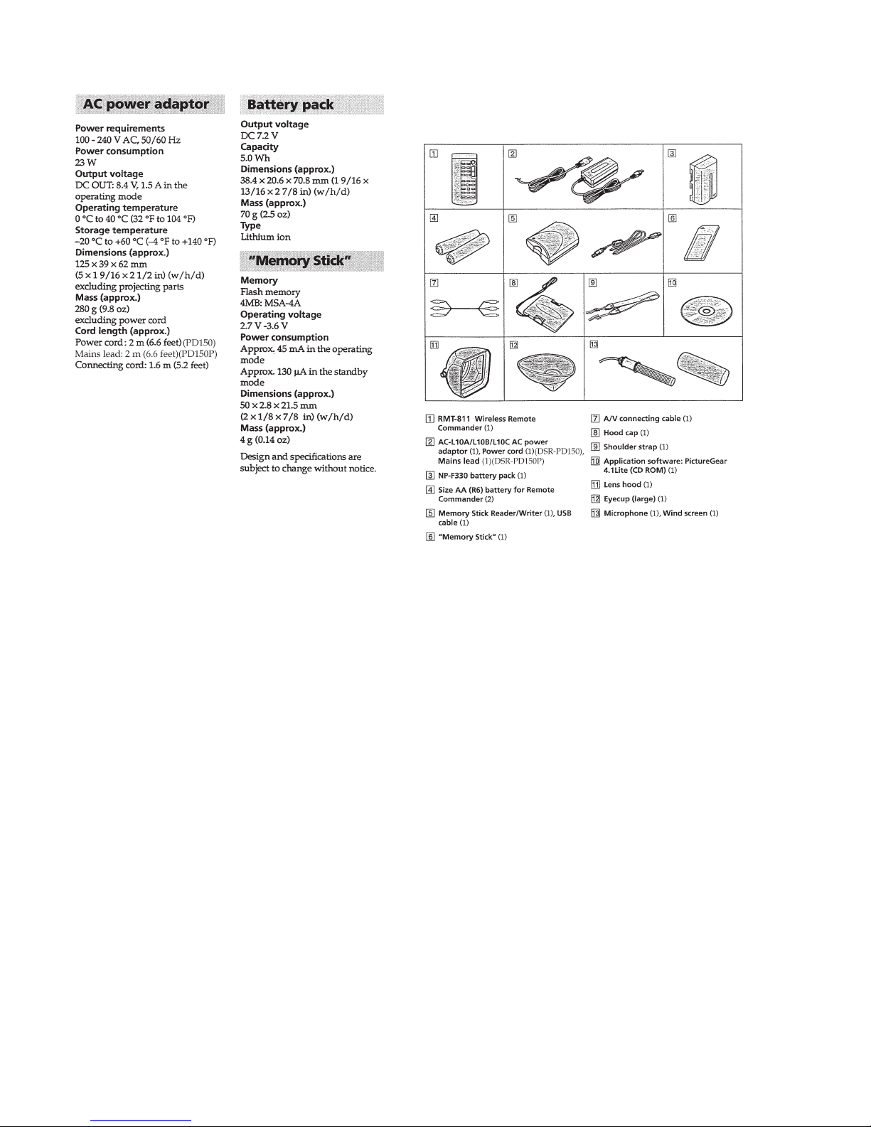
C MECHANISM
— Continued on next page —
Photo : DSR-PD150
US Model
Canadian Model
DSR-PD150
AEP Model
DSR-PD150P
DIGITAL CAMCORDER
SPECIFICATIONS
NTSC model : DSR-PD150
PAL model : DSR-PD150P
DSR-PD150/PD150P
RMT-811
Ver 1.0 2000. 05
— 2 —
1. Check the area of your repair for unsoldered or poorly-soldered
connections. Check the entire board surface for solder splashes
and bridges.
2. Check the interboard wiring to ensure that no wires are
"pinched" or contact high-wattage resistors.
3. Look for unauthorized replacement parts, particularly
transistors, that were installed during a previous repair . Point
them out to the customer and recommend their replacement.
4. Look for parts which, through functioning, show obvious signs
of deterioration. Point them out to the customer and
recommend their replacement.
5. Check the B+ voltage to see it is at the values specified.
6. Flexible Circuit Board Repairing
• Keep the temperatur e of the soldering iron around 270˚C
during repairing.
• Do not touch the soldering iron on the same conductor of the
circuit board (within 3 times).
• Be careful not to apply force on the conductor when soldering
or unsoldering.
SAFETY CHECK-OUT
After correcting the original service problem, perform the following
safety checks before releasing the set to the customer.
SAFETY-RELATED COMPONENT WARNING!!
COMPONENTS IDENTIFIED BY MARK 0 OR DOTTED LINE WITH
MARK 0 ON THE SCHEMATIC DIAGRAMS AND IN THE PARTS
LIST ARE CRITICAL TO SAFE OPERATION. REPLACE THESE
COMPONENTS WITH SONY PARTS WHOSE PART NUMBERS
APPEAR AS SHOWN IN THIS MANUAL OR IN SUPPLEMENTS
PUBLISHED BY SONY .
ATTENTION AU COMPOSANT AYANT RAPPORT
À LA SÉCURITÉ!
LES COMPOSANTS IDENTIFÉS P AR UNE MARQUE 0 SUR LES
DIAGRAMMES SCHÉMA TIQUES ET LA LISTE DES PIÈCES SONT
CRITIQUES POUR LA SÉCURITÉ DE FONCTIONNEMENT. NE
REMPLACER CES COMPOSANTS QUE PAR DES PIÈSES SONY
DONT LES NUMÉROS SONT DONNÉS DANS CE MANUEL OU
DANS LES SUPPÉMENTS PUBLIÉS PAR SONY.
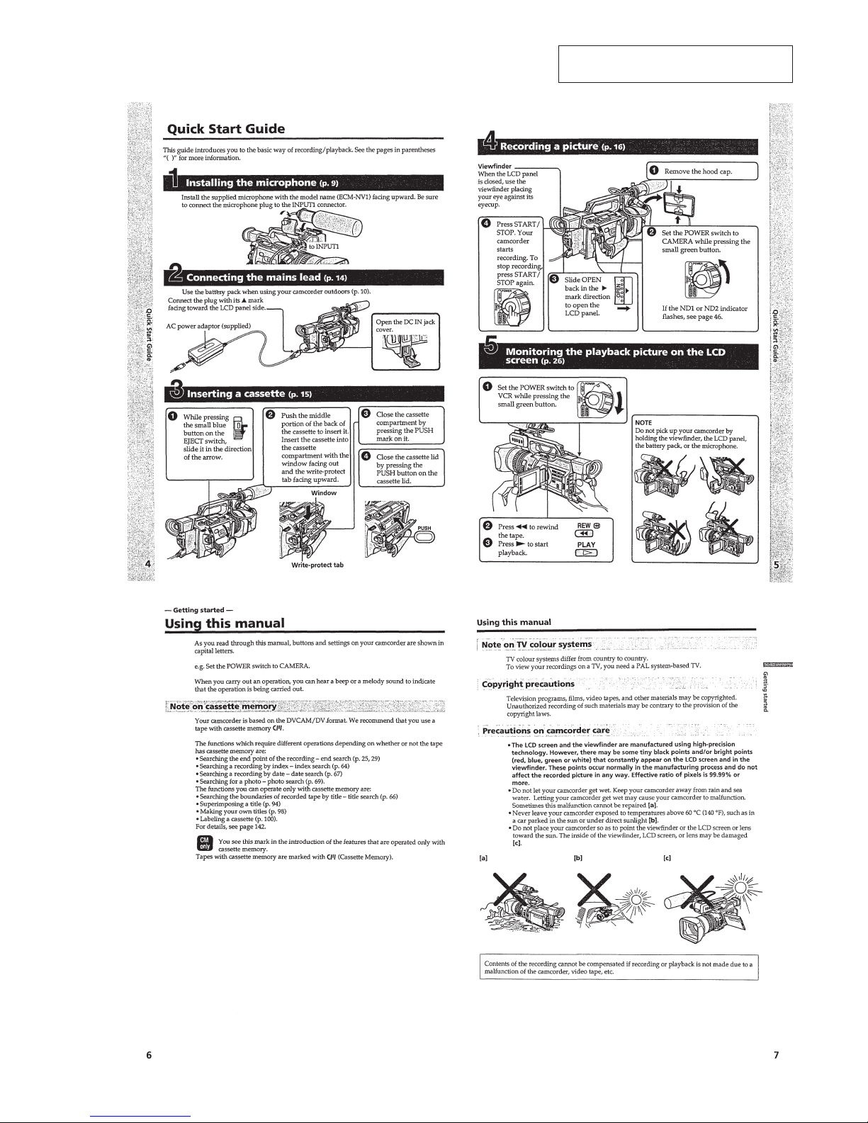
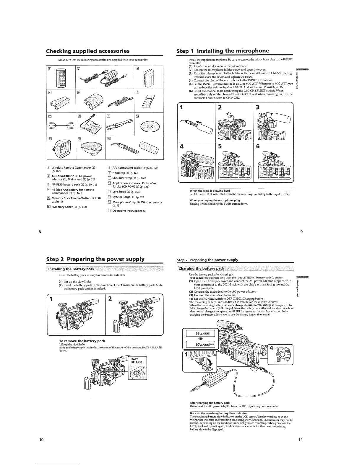
• SUPPLIED ACCESSORIES
Check that the following accessories are supplied with your
camcorder.

— 6 —
3-1-2.Precautions on Adjusting···············································5-58
3-1-3.HOW TO ENTER RECORD MODE WITHOUT
CASSETTE ···································································5-58
3-1-4.HOW TO ENTER PLAYBACK MODE WITHOUT
CASSETTE ···································································5-58
3-1-5.Adjusting Connectors ···················································· 5-59
3-1-6.Connecting the Equipment ············································5-59
3-1-7.Alignment Tapes····························································5-60
3-1-8.Input/Output Level and Impedance ·······························5-60
3-2. SYSTEM CONTROL SYSTEM ADJUSTMENT ········5-61
1. Initialization of A, B, C, D, E, F, 8 Page Data···············5-61
2. Serial No. Input ·····························································5-61
2-1. Company ID Input·························································5-61
2-2. Serial No. Input ·····························································5-61
3. Battery End Adjustment ················································5-63
3-3. SERVO AND RF SYSTEM ADJUSTMENT ···············5-64
1. Cap FG Duty Adjustment (VC-242D board) ················5-64
2. T reel FG Duty Adjustment (VC-242D board) ·············5-64
3. PLL f0 & LPF f0 Adjustment (VC-242D board)············ 5-64
4. Switching Position Adjustment (VC-242D board)········5-65
5. AGC Center Level and APC & AEQ Adjustment ·········5-65
5-1. Preparations before adjustments····································5-65
5-2. AGC Center Level Adjustment (VC-242D board) ········5-65
5-3. APC & AEQ Adjustment (VC-242D Board) ················5-66
5-4. Processing after Completing Adjustments ····················5-66
6. PLL f0 & LPF f0 Final Adjustment (VC-242D board)···5-66
3-4. VIDEO SYSTEM ADJUSTMENTS·····························5-67
3-4-1.Base Band Block Adjustments ······································5-67
1. Chroma BPF f0 Adjustment (VC-242D board) ·············5-67
2. S VIDEO OUT Y Level Adjustment (VC-242D board) ·· 5-67
3. S VIDEO OUT Chroma Level Adjustment
(VC-242D board) ··························································5-68
4.
VIDEO OUT Y, Chroma Level Check (VC-242D board)··
5-68
3-4-2. BIST Check ··································································5-69
1. Playback System Check ················································5-69
1-1. Preparations for Playback··············································5-69
1-2. IC301 TRX (RF) PB BIST Check·································5-69
1-3. IC301 AUD (ABUS) PB BIST Check ···························5-69
1-4. IC301 VFD PB BIST Check ·········································5-69
1-5. IC301 ENCODER BIST Check ····································5-70
1-6. Processing after Completing Playback System Check··5-70
3-5. AUDIO SYSTEM ADJUSTMENTS ····························5-71
1. Playback Level Check ···················································5-72
2. Overall Level Characteristics Check ·····························5-72
3. Overall Distortion Check···············································5-72
4. Overall Noise Level Check············································ 5-72
5. Overall Separation Check·············································· 5-72
5-4. SERVICE MODE ··························································5-73
4-1. ADJUSTMENT REMOTE COMMANDER ················5-73
1. Using the adjustment remote commander ·····················5-73
2. Precautions upon using the adjustment remote
commander ····································································5-73
4-2. DATA PROCESS···························································5-74
4-3. SERVICE MODE ··························································5-75
1. Setting the Test Mode ····················································5-75
2. Emergence Memory Address ········································5-75
2-1. EMG Code (Emergency Code) ·····································5-75
2-2. MSW Code ····································································5-76
3. Bit value discrimination ················································5-77
4. Switch check (1) ····························································5-77
5. Switch check (2) ····························································5-78
6. Record of Use check······················································5-78
7. Record of Self-diagnosis check ·····································5-79
8. HRS METER (Hours meter) ·········································5-80
6. REPAIR PARTS LIST
6-1. EXPLODED VIEWS ······················································6-1
6-1-1.OVERALL SECTION-1 ·················································6-1
6-1-2.OVERALL SECTION-2 ·················································6-2
6-1-3.CABINET (L) SECTION················································6-3
6-1-4.CABINET (R) SECTION-1 ············································6-4
6-1-5.CABINET (R) SECTION-2 ············································6-5
6-1-6.UPPER HANDLE SECTION ·········································6-6
6-1-7.BATTERY PANEL SECTION ········································6-7
6-1-8.EVF SECTION································································6-8
6-1-9.CENTER FRAME SECTION ·········································6-9
6-1-10. LENS BLOCK SECTION ··········································6-10
6-1-11. CASSETTE COMPARTMENT, DRUM AND
REEL TABLE ASSEMBLY ········································ 6-11
6-1-12. TAPE GUIDE, PINCH SLIDER ASSEMBLY AND
BRAKE SLIDER ASSEMBLY···································6-12
6-1-13. EACH GEARS AND LOADING/CAPSTAN MOTOR
ASSEMBLY ································································6-13
6-2. ELECTRICAL PARTS LIST ········································6-14
* Color reproduction frame is shown on page 329.
— 7 —
SERVICE NOTE
1. POWER SUPPLY DURING REPAIRS
In this unit, about 10 seconds after power is supplied to the battery terminal using the regulated power supply (8.4V), the po wer is shut of f so
that the unit cannot operate.
These following two methods are available to prevent this. Take note of which to use during repairs.
Method 1.
Connect the servicing remote commander RM-95 (J-6082-053-B) to the LANC jack, and set the commander switch to the “ADJ” side.
Method 2.
Use the DC IN terminal. (Use the AC power adaptor. (AC-L10, AC-VQ800 etc. ))
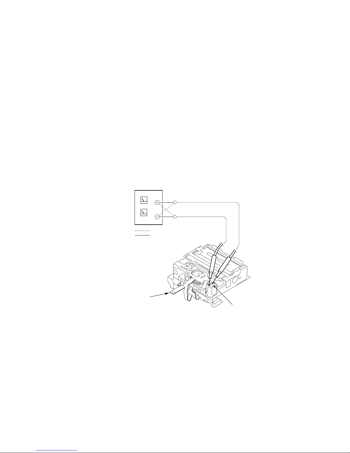
2. TO TAKE OUT A CASSETTE WHEN NOT EJECT (FORCE EJECT)
1 Refer to 2-3. to remove the upper handle block assembly.
2 Refer to 2-5. to remove the cabinet (L) assembly.
3 Refer to 2-5. to remove the mechanism deck (Including VC-242D board and DD-138D board).
4 Remove DD-138D board from the mechanism deck (Including VC-242D board).
5 Remove the CN022 (27P 0.3 mm) of VC-242D board.
6 Supply +4.5V from the DC power supply to the loading motor and unload with a pressing the cassette compartment.
Loading motor
DC power supply (+4.5V)
Disconnect from CN022 (27P)
of VC-242D board.
: loading
: unloading
What to do when a user forgets a password
This camcorder has the forced log insertion function. A passw ord is inputted, and this function is set up. When this function was set up, this
camcorder doesn’t move if the memory stick which memorize a correct logo isn’t inserted. To release the for ced logo function, the correct
password must be input.
This password is memorized in the IC1105 (EEPROM) on VC-242D board. Therefore, when a user for gets the password, replace the IC1105.
This IC1105 memorizes the HRS METER data (Hour meter data: page A, address 00 to 13), too. Therefor e, replace the IC1105 in the
following order to copy the HRS METER data.
Replacing procedure:
1) Note down the data of page A, address 00 to 13.
2) Replace IC1105 (EEPROM) on VC-242D board.
3) To page A, address 00 to 13, input the data noted down.
(Refer to “HRS METER (Hours meter)” of “5-4. SERVICE MODE”)
— 8 —
SELF-DIAGNOSIS FUNCTION
1. SELF-DIAGNOSIS FUNCTION
When problems occur while the unit is operating, the self-diagnosis
function starts working, and displays on the viewfinder , LCD screen
or LCD window what to do. This function consists of two display;
self-diagnosis display and service mode display.
Details of the self-diagnosis functions are provided in the Instruction
manual.
Note: The “self-diagnosis display” data will be backed up by the coin-type lithium battery of CK-093 board BT250. When CK-093 board is removed,
the “self-diagnosis display” data will be lost by initialization.
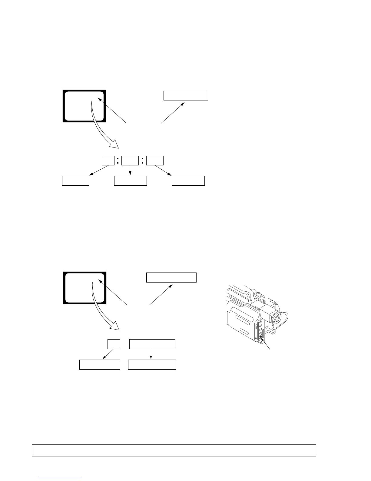
2. SELF-DIAGNOSIS DISPLAY
When problems occur while the unit is operating, the counter of the
viewfinder, LCD screen or LCD window consists of an alphabet
and 4-digit numbers, which blinks at 3.2 Hz. This 5-character display
indicates the “repaired by:”, “block” in which the problem occurred,
and “detailed code” of the problem.
3. SERVICE MODE DISPLAY
The service mode display shows up to six self-diagnosis codes shown in the past.
3-1. Display Method
While pressing the “STOP” key, set the switch from OFF to “VCR or PLAYER”, and continue pressing the “STOP” key for 5 seconds
continuously. The service mode will be displayed, and the counter will show the backup No. and the 5-character self-diagnosis codes.
3-2. Switching of Backup No.
By rotating the control dial, past self-diagnosis codes will be shown in order. The backup No. in the [] indicates the order in which the
problem occurred. (If the number of problems which occurred is less than 6, only the number of problems which occurred will be shown.)
[1] : Occurred first time [4] : Occurred fourth time
[2] : Occurred second time [5] : Occurred fifth time
[3] : Occurred third time [6] : Occurred the last time
3-3. End of Display
Turning OFF the power supply will end the service mode display.
Order of previous errors
Backup No.
Self-diagnosis Codes
C : 3 1 : 1 1
[3]
Lights up
Viewfinder or LCD screen
[3] C : 3 1 : 1 1
3 C : 3 1 : 11
LCD window
1 1
3 1
C : 3 1 : 11
C
Repaired by:
Refer to page 9.
Self-diagnosis Code Table.
Indicates the appropriate
step to be taken.
E.g.
31 ....Reload the tape.
32 ....Tu r n o n power again.
Block
Detailed Code
Blinks at 3.2Hz
C : Corrected by customer
H : Corrected by dealer
E : Corrected by service
engineer
Viewfinder or LCD screen LCD window
C : 3 1 : 1 1
Control dial
— 9 —
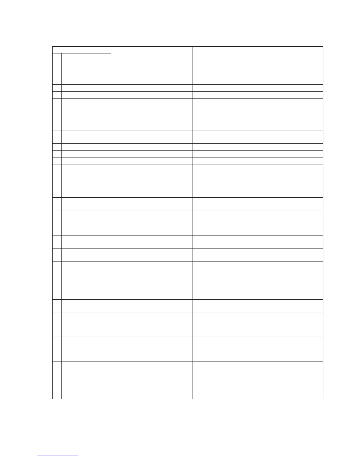
4. SELF-DIAGNOSIS CODE TABLE
C
C
C
C
C
C
C
C
C
C
C
C
C
C
C
C
C
C
C
C
C
C
C
E
E
E
E
Block
Function
04
21
22
31
31
31
31
31
31
31
31
31
31
31
31
32
32
32
32
32
32
32
32
61
61
62
62
Detailed
Code
00
00
00
10
11
20
21
22
23
24
30
40
42
10
11
20
21
22
23
24
30
40
42
00
10
00
01
Symptom/State
Non-standard battery is used.
Condensation.
Video head is dirty.
LOAD direction. Loading does not
complete within specified time
UNLOAD direction. Loading does not
complete within specified time
T reel side tape slacking when unloading
.
Winding S reel fault when counting the
rest of tape.
T reel fault.
S reel fault.
T reel fault.
FG fault when starting capstan.
FG fault when starting drum.
FG fault during normal drum operations.
LOAD direction loading motor time-
out.
UNLOAD direction loading motor
time-out.
T reel side tape slacking when
unloading.
Winding S reel fault when counting the
rest of tape.
T reel fault.
S reel fault.
T reel fault.
FG fault when starting capstan.
FG fault when starting drum
FG fault during normal drum
operations
Difficult to adjust focus
(Cannot initialize focus.)
Zoom operations fault
(Cannot initialize zoom lens.)
Steadyshot function does not work well.
(With pitch angular velocity sensor output
stopped.)
Steadyshot function does not work well.
(With yaw angular velocity sensor output
stopped.)
Self-diagnosis Code
Repaired by:
Correction
Use the info LITHIUM battery.
Remove the cassette, and insert it again after one hour.
Clean with the optional cleaning cassette.
Load the tape again, and perform operations from the beginning.
Load the tape again, and perform operations from the beginning.
Load the tape again, and perform operations from the beginning.
Load the tape again, and perform operations from the beginning.
Load the tape again, and perform operations from the beginning.
Load the tape again, and perform operations from the beginning.
Load the tape again, and perform operations from the beginning.
Load the tape again, and perform operations from the beginning.
Load the tape again, and perform operations from the beginning.
Load the tape again, and perform operations from the beginning.
Remove the battery or power cable, connect, and perform
operations from the beginning.
Remove the battery or power cable, connect, and perform
operations from the beginning.
Remove the battery or power cable, connect, and perform
operations from the beginning.
Remove the battery or power cable, connect, and perform
operations from the beginning.
Remove the battery or power cable, connect, and perform
operations from the beginning.
Remove the battery or power cable, connect, and perform
operations from the beginning.
Remove the battery or power cable, connect, and perform
operations from the beginning.
Remove the battery or power cable, connect, and perform
operations from the beginning.
Remove the battery or power cable, connect, and perform
operations from the beginning.
Remove the battery or power cable, connect, and perform
operations from the beginning.
Inspect the lens block focus reset sensor (Pin wg of LA-026 board)
when focusing is performed when the control dial is rotated in the
focus manual mode, and the focus motor drive circuit (IC140 of
LA-026 board) when the focusing is not performed.
Inspect the lens block zoom reset sensor (
Pin ws of LA-026 board
)
when zooming is performed when the zoom lens is operated and
the zoom motor drive circuit (IC140 of LA-026 board) when
zooming is not performed.
Inspect pitch angular velocity sensor (SE601 or SE602 of SE-108
board) peripheral circuits.
Inspect yaw angular velocity sensor (SE600 or SE603 of SE-108
board) peripheral circuits.
1-1
SECTION 1
GENERAL
DSR-PD150/PD150P
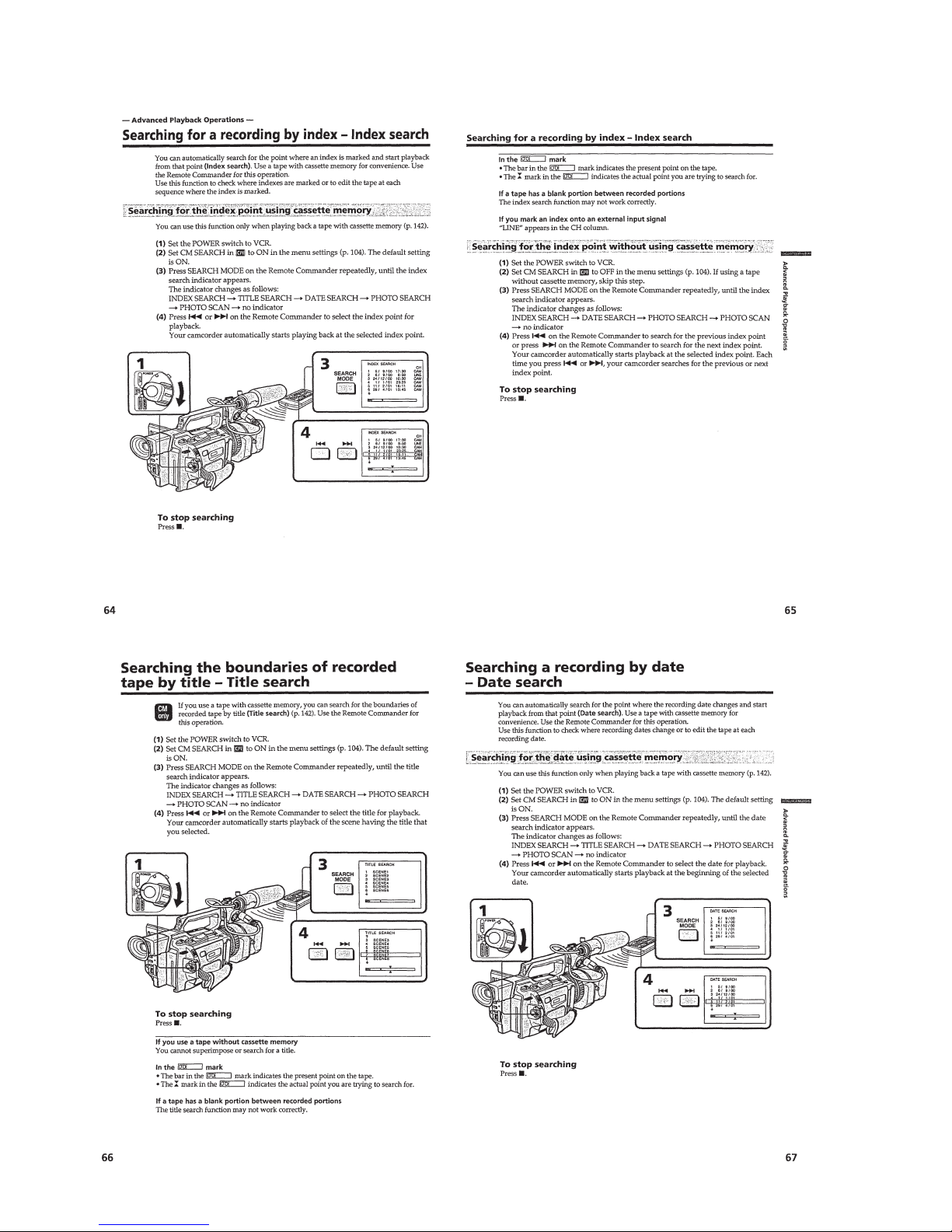
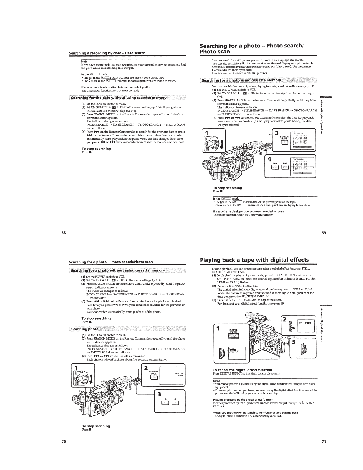
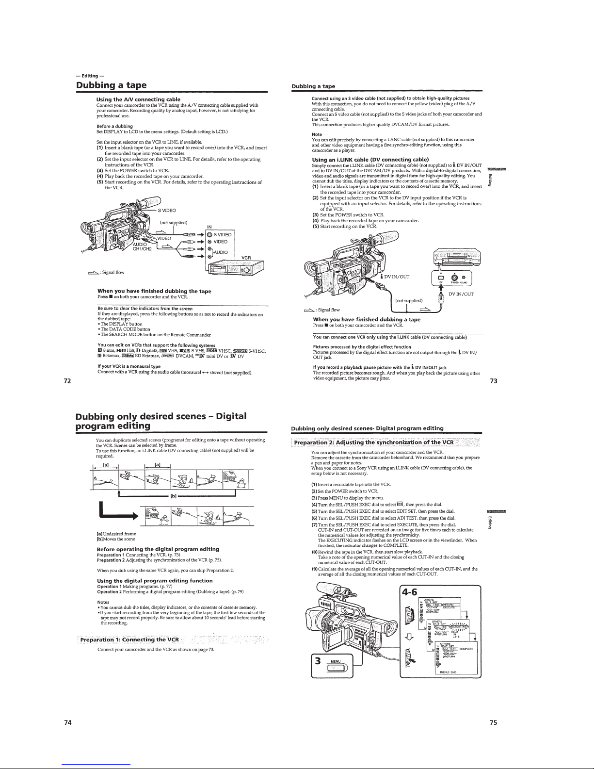
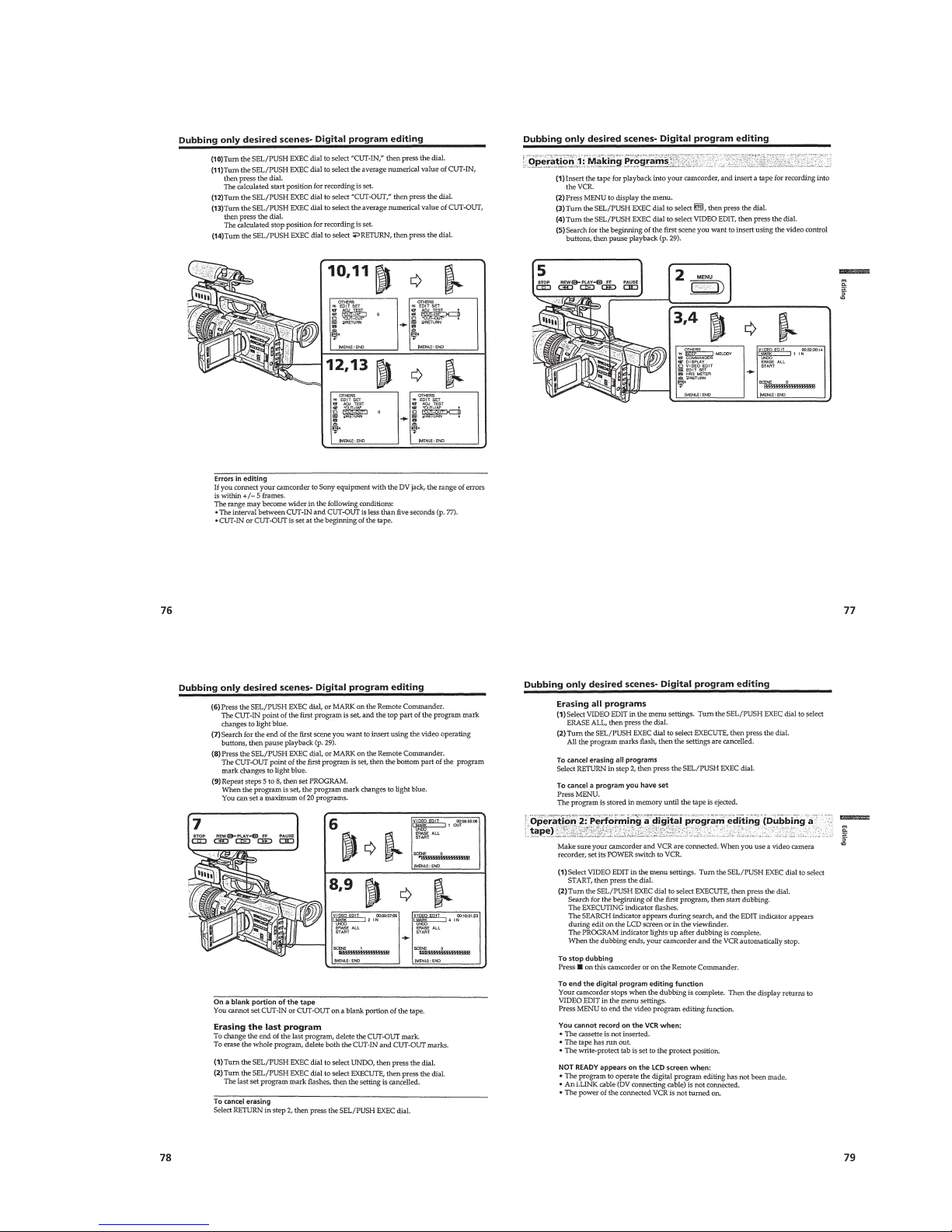
This section is extracted from instruction
manual. (DSR-PD150P)
1-2
1-6

1-7
1-8
1-9

1-10

1-11
1-12
1-13
1-14

1-15
1-16
1-17
1-18
1-19
1-20
1-22
1-21
1-23
1-24
1-25
1-26
1-27
 Loading...