

Sony DVCAM DSR-80, DVCAM DSR-80P Operating Instructions Manual

1997 by Sony Corporation
3-860-358-13(2)
Digital
Videocassette
Recor der
Operating Instructions
Before operating the unit, please read this manual
thoroughly and retain it for future reference.
DSR-80/80P
Owner’s Record
The model and serial numbers are located at the rear.
Record the serial number in the space provided below.
Refer to these numbers whenever you call upon your Sony
dealer regarding this product.
Model No. DSR-80 Serial No.
WARNING
To prevent fire or shock hazard, do not
expose the unit to rain or moisture.
This symbol is intended to alert the user to the
presence of uninsulated “dangerous voltage”
within the product’s enclosure that may be of
sufficient magnitude to constitute a risk of
electric shock to persons.
This symbol is intended to alert the user to the
presence of important operating and
maintenance (servicing) instructions in the
literature accompanying the appliance.
For the customers in the USA
This equipment has been tested and found to comply with the
limits for a Class A digital device, pursuant to Part 15 of the
FCC Rules. These limits are designed to provide reasonable
protection against harmful interference when the equipment
is operated in a commercial environment. This equipment
generates, uses, and can radiate radio frequency energy
and, if not installed and used in accordance with the
instruction manual, may cause harmful interference to radio
communications. Operation of this equipment in a residential
area is likely to cause harmful interference in which case the
user will be required to correct the interference at his own
expense.
You are cautioned that any changes or modifications not
expressly approved in this manual could void your authority
to operate this equipment.
This device requires shielded interface cables to comply with
FCC emission limits.
Caution
Television programs, films, video tapes and other materials
may be copyrighted.
Unauthorized recording of such material may be contrary to
the provisions of the copyright laws.
Voor de klanten in Nederland
Bij dit produkt zijn batterijen geleverd.
Wanneer deze leeg zijn, moet u ze niet
weggooien maar inleveren als KCA.
2

Table of Contents 3
Chapter 3
Convenient
Functions for
Editing Operation
Chapter 1
Overview
Table of Contents
Features .............................................................................5
Location and Function of Parts .......................................8
Front Panel .......................................................................... 8
Rear Panel ......................................................................... 14
Recording ........................................................................19
Settings for Recording....................................................... 19
Usable Cassettes................................................................ 22
Recording Procedure ......................................................... 24
Playback...........................................................................28
Settings for Playback......................................................... 28
Playback Procedure ........................................................... 29
Setting the Time Data......................................................31
Displaying Time Data and Operation Mode Indications... 31
Using the Internal Time Code Generator .......................... 33
Synchronizing Internal and External Time Codes............. 34
Rerecording the Time Code — TC Insert Function .......... 35
High-Speed and Low-Speed Search: Quickly and
Accurately Determining Editing Points ................37
Search Operations via External Equipment ...................... 37
Search Operations on This Unit ........................................ 37
Dubbing Signals in QSDI Format — QSDI Dubbing
Function...................................................................38
Chapter 2
Recording and
Playback

4 Table of Contents
Table of Contents
Chapter 5
Connections and
Settings
Chapter 6
Maintenance and
Troubleshooting
Appendix
Chapter 4
Menu Settings
Menu Organization..........................................................41
Menu Contents ................................................................42
SETUP menu..................................................................... 42
Changing Menu Settings ................................................51
Buttons Used to Change Settings ...................................... 51
Changing the Settings of Basic Items ............................... 51
Displaying Enhanced Items............................................... 53
Changing the Settings of Enhanced Items......................... 53
Returning Menu Settings to Their Factory
Defaults ........................................................................ 54
Displaying Supplementary Status Information ............55
Connections for a Digital Non-Linear Editing
System .....................................................................57
Connections for a Cut Editing System..........................58
Connections for an A/B Roll Editing System ...............59
Connections for QSDI Dubbing .....................................64
Connections for Analog Recording...............................65
Adjusting the Sync and Subcarrier Phases..................66
Maintenance ....................................................................69
Condensation ..................................................................... 69
Regular Checks ................................................................. 69
Head Cleaning ................................................................... 70
Troubleshooting ..............................................................71
Error Messages .................................................................. 73
Alarm Messages ................................................................ 73
Notes on Use ...................................................................77
Specifications..................................................................78
Glossary...........................................................................81
Index.................................................................................83

Chapter 1 Overview
Chapter 1 Overview 5
Features
The DSR-80/80P is a 1/4-inch digital video cassette
recorder that uses the DVCAM digital recording
format. This system achieves stable, superb picture
quality by digitally processing video signals that are
separated into color difference signals and luminance
signals (component method).
The DSR-80/80P unit is equipped with the variety of
functions that are needed for videocassette recorders
and players used in professional digital video editing
systems. It supports the ClipLink™ function
developed by Sony Corporation for highly efficient
video editing. When connected to a Sony
EditStation™, the unit serves as part of a powerful
non-linear editing system
1)
.
The unit is also equipped with a full-fledged analog
interface to support hybrid systems that combine
conventional analog equipment with digital equipment.
The DSR-80/80P’s main features are described below.
DVCAM Format
DVCAM is based on the consumer DV format, which
uses the 4:1:1 component digital format, and provides
a
1
/4-inch digital recording format for professional use.
High picture quality, high stability
Video signals are separated into color difference
signals and luminance signals, which are encoded and
compressed to one-fifth size before being recorded to
ensure stable and superb picture quality.
Because the recording is digital, multi-generation
dubbing can be performed with virtually no
deterioration of quality.
Wide track pitch
The recording track pitch is 15 µm, fully 50 percent
wider than the DV format’s 10-µm track pitch. Thanks
to this feature, the DVCAM format sufficiently meets
the reliability and precision requirements of
professional editing.
High-quality PCM digital audio
PCM recording makes for a wide dynamic range and a
high signal-to-noise ratio, thereby enhancing sound
quality.
There are two recording modes: 2-channel mode (48kHz sampling and 16-bit quantization), which offers
sound quality equivalent to the DAT (Digital Audio
Tape) format, or 4-channel mode (32-kHz sampling
and 12-bit quantization).
Playback compatibility with DV format
A DV cassette recorded on a DV-format VCR can be
played back on this unit. (Cassettes recorded in LP
mode cannot be played back.)
Choice of two cassette sizes
The unit can use both standard-size and mini-size
DVCAM cassettes.
•According to cassette size, it automatically changes
the position of the reel drive plate.
•The maximum recording/playback times are 184
minutes for standard size cassettes and 40 minutes for
mini-size cassettes.
Chapter 1 Overview
........................................................................................................................................................................................................
1) Non-linear editing
This is an editing method that uses video and audio
signals that have been digitally encoded and recorded on
a hard disk as digital data. When compared with
conventional (linear) editing methods, non-linear editing
offers vastly improved efficiency in editing operations,
such as by eliminating tape transport time.

Features
Chapter 1 Overview
6 Chapter 1 Overview
A Wealth of Interfaces
Digital interfaces
The unit provides the following two digital interfaces.
•SDTI (QSDI)
1)
: This interface enables SDTI (QSDI)format video, audio and time code signals to be
transferred between this unit and the Sony EditStation
at normal speed.
•AES/EBU interface : This interface enables AES/
EBU-format digital audio signals to be input and
output.
As an option, you can also use the SDI (Serial Digital
Interface) as an interface for D1 (component) format
digital video and audio signals.
Analog interfaces
The unit also comes with analog interfaces enabling it
to be connected to analog video and audio equipment.
•Analog video : These interfaces include a component
interface (can be switched to RGB), composite
interface, and S-video interface.
•Analog audio : 4-channel input and 4-channel output
are both provided.
Facilities for High-efficiency
Editing
The unit provides an abundance of functions that
enhance editing efficiency and precision.
Supports ClipLink function
In response to commands sent from the EditStation,
index pictures that are recorded on tape or ClipLink
log data that is recorded in the cassette memory can be
transferred to the EditStation. The EditStation
operator can then efficiently use these pictures and
data in a preliminary editing session.
For more information about the ClipLink function, refer to
the “ClipLink Guide” also supplied with this unit.
Internal time code generator/reader
The unit contains a time code generator/reader which
can generate and read longitudinal time code (LTC) in
the SMPTE format (DSR-80) or EBU format (DSR80P), to ensure frame-accurate editing.
When the unit is equipped with an optional DSBK130/130P Time Code Input/Output Board, it can
output the time code read from tape as analog (LTC)
signal, and receive externally generated time code
(LTC).
Remote control
The unit can be operated by remote control from an
editing controller that supports the RS-422A interface
or from on optional SIRCS
2)
-system remote controller
such as the DSRM-10 or SVRM-100A.
High-speed search function
The unit has a picture search function that allows you
to view color picture at playback speeds up to 32 times
normal speed in forward and reverse directions.
When remote-controlling this unit in shuttle mode
from an editing controller or a remote controller, you
can search at any speed in the range 0 (still) to 32
times normal in both directions. You can also search
frame-by-frame in jog mode.
At search speeds up to 5 times normal, you can also
hear playback audio.
........................................................................................................................................................................................................
1) QSDI is a type of SDTI.
SDTI is the name of a standard interface established as
SMPTE 305M.
This unit uses SDTI to transmit DV data, and the input/
output connectors are labeled “SDTI(QSDI)”.
In indicator and menu indications, however, the
“SDTI(QSDI)” name is shortened to “QSDI”.
In the remainder of this manual, the short form (“QSDI”)
is used.
2) SIRCS (Sony Integrated Remote Control System)
A command protocol to remote control Sony
professional videocassette recorders/players.

Chapter 1 Overview
Chapter 1 Overview 7
Digital slow-motion playback
Using the frame memory function, the unit can show
noise-free slow-motion playback at speeds ranging
from 0 to
1
/5 normal in both directions. Frame-byframe or field-by-field playback of still pictures is also
possible.
Jog audio function
When in jog mode, audio can be monitored at
playback speeds ranging from normal to
1
/30 normal in
both directions. The audio signals are once stored in
memory and then played back at the same rate as the
search speed. This allows you to use audio playback
to find the desired edit points.
Built-in TBC (Time Base Corrector)
A digital TBC is built in to ensure jitter-free video
output during analog editing.
Other Features
Menu system for functionality and
operation settings
The unit provides a menu system to make its various
functions easier to use and set up its operation
conditions.
Superimposition function
Time code numbers, operation mode indications,
menus, error messages, and other text data can be
superimposed and output in analog composite video
signals.
Easy maintenance functions
•Self-diagnostic/alarm function : This function
automatically detects setup and connection errors,
operation faults, and other problems. It also displays
a description of the problem, its cause, and the
recommended response on the video monitor screen
or time counter display.
•Digital hours meter : The unit’s digital hours meter
functions include four kinds of tally operations for
operating hours, head drum usage hours, tape
transport hours, and tape threading/unthreading times.
The tally results can be viewed on the video monitor
or the time counter display.
Rack mountable
When you use the optional RMM-130 Rack Mount
Kit, you can mount this unit onto an EIA-standard 19inch rack (height = 4 units).
Optional Accessories
DSBK-120/120P SDI (Serial Digital
Interface) Input/Output Board
When installed in the DSR-80/80P, this board enables
digital video and audio signals in the D1 format to be
input to and output from the unit.
DSBK-130/130P Time Code Input/Output
Board
When installed in the DSR-80/80P, this board enables
SMPTE or EBU-format time code (LTC) to be input to
and output from the unit.
RMM-130 Rack Mount Kit
This kit can be used to mount the DSR-80/80P onto an
EIA-standard 19-inch rack.
Features
Chapter 1 Overview
8 Chapter 1 Overview
)
0
6
r
p
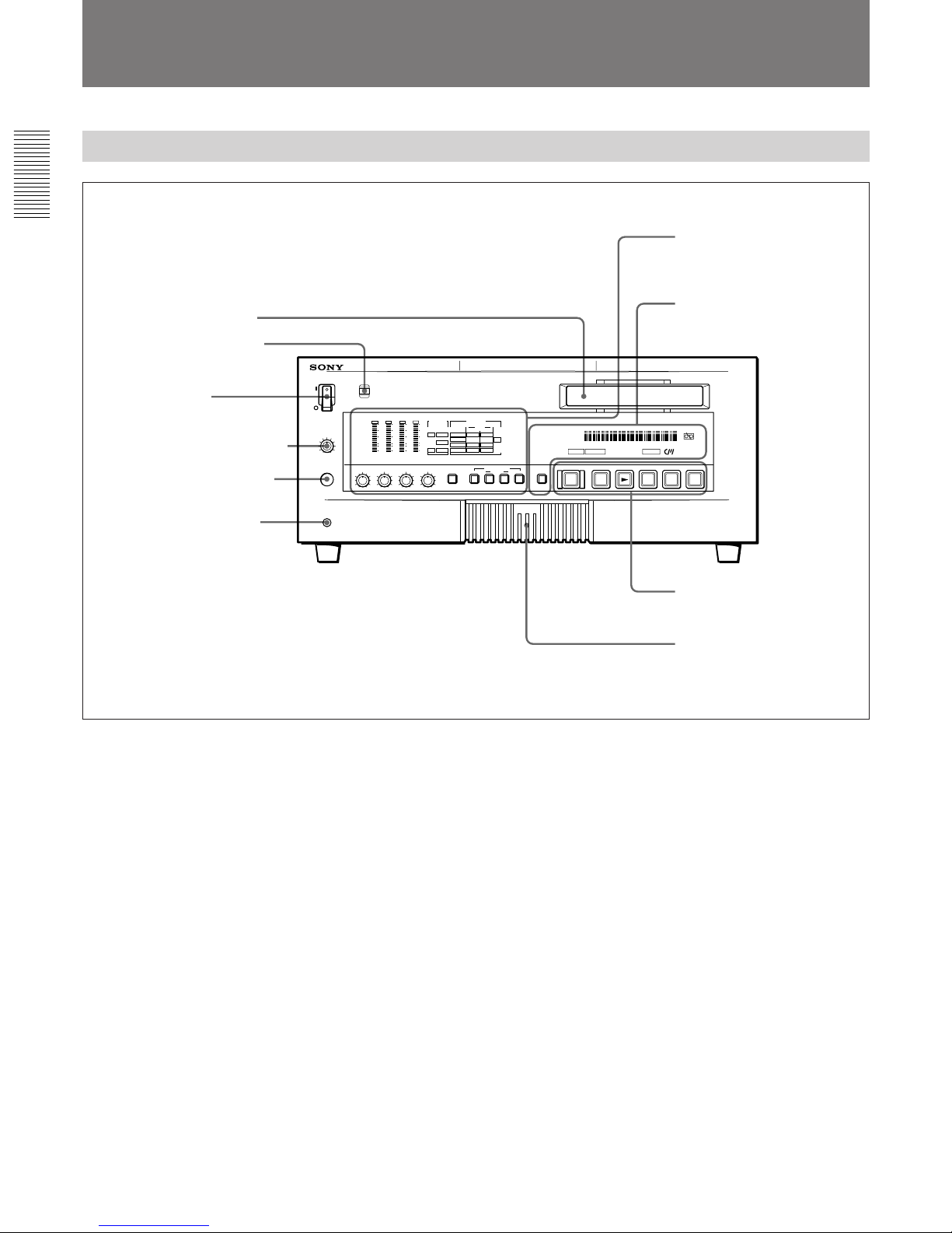
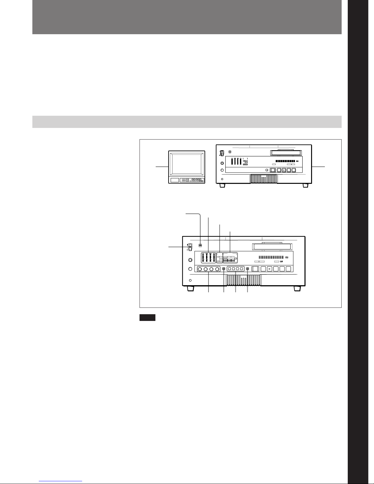
Front Panel
3 POWER switch
Press on the “1” side to power on the unit. This causes
the audio level meter and time counter display to light.
Press on the “¬” side to power off the unit.
4 HEADPHONES control knob
Controls the volume of the headphones connected to
the HEADPHONES connector.
5 HEADPHONES connector (stereo phone jack)
Connect a stereo headphones for headphone
monitoring during recording or playback.
The audio signal you want to monitor can be selected
with the MONITOR SELECT switches on the menu
control panel 4.
6 CONTROL S connector (stereo minijack)
Connect a SIRCS-system remote controller such as the
DSRM-10 or SVRM-100A.
Location and Function of Parts
1 Cassette compartment
Accepts standard-size or mini-size DVCAM digital
videocassettes. When using a mini-size cassette, insert
it into the middle of the compartment.
For details of usable cassettes, see page 22.
2 REMOTE/LOCAL switch
Selects whether the unit is operated from its front
panel or from external (remote) equipment.
REMOTE : The unit is operated from an editing
controller connected to the REMOTE connector
on the rear panel.
LOCAL : The unit is operated from its front panel or
from a SIRCS-system remote controller connected
to the CONTROL S connector on the front panel.
1 Display section (A) and
video/audio input setting
section (see page 9)
2 Display section (B) and
COUNTER SELECT button
(see page 11)
3 Tape transport control
section (see page 12)
4 Menu control panel
(inside of the door)
(see page 13)
1 Cassette compartment
4 HEADPHONES control knob
2 REMOTE/LOCAL switch
5 HEADPHONES connector
6 CONTROL S connector
3 POWER switch
Chapter 1 Overview
Chapter 1 Overview 9
AUDIO INPUT LEVEL AUDIO REC
SELECT
2CH/4CH
INPUT SELECT
VIDEO AUDIO
QSDI
CH-1
CH-1/2
CH-2
CH-3/4
dB
0
-12
-20
-30
-40
-60
CH-1
AUDIO MODE INPUT MODE
VIDEO
AUDIO
CH-1,1/2 CH-2,3/4
COMPOSITE
ANALOG ANALOG
S VIDEO
COMPONENT
SDI
AES/EBU
SDI
AES/EBU
SDI
2CH
4CH
Fs44.1k
Fs48k
Fs32k
QSDI
CH-2 CH-3 CH-4
CH-1 CH-2 CH-3 CH-4
0
2
46
8
10
0
2
46
8
10
0
2
46
8
10
0
2
46
8
10
OVER
dB
0
-12
-20
-30
-40
-60
OVER
dB
0
-12
-20
-30
-40
-60
OVER
dB
0
-12
-20
-30
-40
-60
OVER
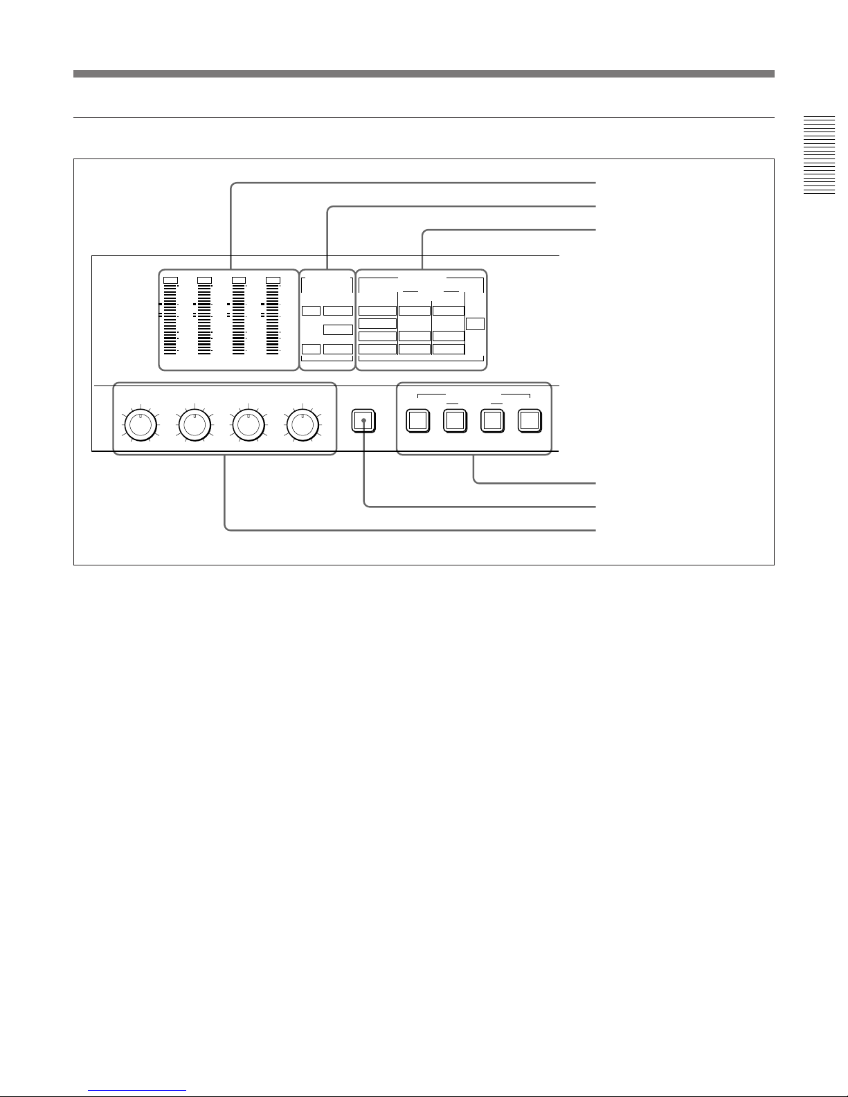
1 Display section (A) and video/audio input setting section
[2CH] and [Fs48k] indicators : Light during
playback of a tape recorded in two-channel mode
(48 kHz), or during two-channel mode (48 kHz)
recording.
[2CH] and [Fs44.1k] indicators : Light during
playback of a tape recorded in two-channel mode
(44.1 kHz).
[4CH] and [Fs32k] indicators : Light during
playback of a tape recorded in four-channel mode
(32 kHz), or during four-channel mode (32 kHz)
recording.
1 Audio level meter
2 AUDIO MODE display
3 INPUT MODE display
4 INPUT SELECT buttons
5 AUDIO REC SELECT button
6 AUDIO INPUT LEVEL control
knobs
1 Audio level meter
Indicates the recording level during recording or EE
mode
1)
and the playback level during playback. When
the audio level exceeds 0 dB, the OVER indicator
lights.
The short bars to the left of some level indication bars
indicate that those levels are reference audio recording
levels.
2 AUDIO MODE display
Indicates the audio mode during playback or recording
or while in EE mode.
•During playback it indicates the audio mode in which
the tape was recorded.
•During recording or while in EE mode, it indicates
the currently selected audio recording mode. The
AUDIO REC SELECT button is used for audio
recording mode selection.
........................................................................................................................................................................................................
1) EE mode
“EE” stands for “Electric to Electric”. When in this
mode, the video and audio signals that are input to the
VCR’s recording circuitry do not pass through any
magnetic conversion circuits but instead are output via
electric circuits only. This mode is used to check input
signals and adjust input levels.

Features
Chapter 1 Overview
10 Chapter 1 Overview
3 INPUT MODE display
Indicates the format of the currently selected video and
audio input signals.
VIDEO indicators : The corresponding indicator
lights when the selected video input signal is in
the composite analog, S-video, component analog,
or SDI (serial digital interface) format.
AUDIO CH-1, 1/2 indicators : The ANALOG,
AES/EBU or SDI indicator lights for the
corresponding format of the selected audio signal
being input to channel 1 (when in 2-channel
mode) or to channels 1 and 2 (when in 4-channel
mode).
AUDIO CH-2, 3/4 indicators: The ANALOG,
AES/EBU, or SDI indicator lights for the
corresponding format of the selected audio signal
being input to channel 2 (when in 2-channel
mode) or to channels 3 and 4 (when in 4-channel
mode).
QSDI : Lights when QSDI-format video and audio
input signals have been selected. When QSDI is
selected, all of the indicators in the VIDEO and
AUDIO groups go off.
4 INPUT SELECT buttons
Select video input signals and audio input signals.
VIDEO button : Each press of this button cycles
through four video signal selection options:
composite analog, S-video, component analog,
and SDI. When you select one of these options,
the corresponding VIDEO indicator in the INPUT
MODE display lights up.
AUDIO CH-1, CH-1/2 button : Each press of this
button cycles through three audio signal selection
options for audio channel 1 (when in 2-channel
mode) or channels 1 and 2 (when in 4-channel
mode): analog, AES/EBU, and SDI. When you
select one of these options, the corresponding
AUDIO indicator in the INPUT MODE display
lights up.
AUDIO CH-2, CH-3/4 button : Each press of this
button cycles through three audio signal selection
options for audio channel 2 (when in 2-channel
mode) or channels 3 and 4 (when in 4-channel
mode): analog, AES/EBU, and SDI. When you
select one of these options, the corresponding
AUDIO indicator in the INPUT MODE display
lights up.
QSDI : Press this button to select QSDI signals.
If the selected signal (except for analog audio) is not
supplied to the appropriate connector, the
corresponding indicator flashes in the INPUT MODE
display.
If the unit is not equipped with an optional DSBK-120/
120P SDI Input/Output Board, no SDI indicators light
in the INPUT MODE display no matter how many
times you press the INPUT SELECT buttons.
5 AUDIO REC (recording mode) SELECT button
Selects the audio mode for recording. Each press
toggles between 2-channel mode and 4-channel mode,
and the indicator corresponding to the selected option
lights in the AUDIO MODE display.
Note
This button works only when the unit is in EE mode.
6 AUDIO INPUT LEVEL control knobs
When recording, you can use these knobs to set audio
input levels for CH-1 (channel 1), CH-2, CH-3 and
CH-4, respectively.
You can make these knobs inoperative for an AES/
EBU, SDI or QSDI format digital audio input by
setting “DIGITAL INPUT” under the AUDIO
CONTROL menu item to “BYPASS”.
On how to use the menu, see Chapter 4 “Menu Settings”.
Location and Function of Parts
Chapter 1 Overview
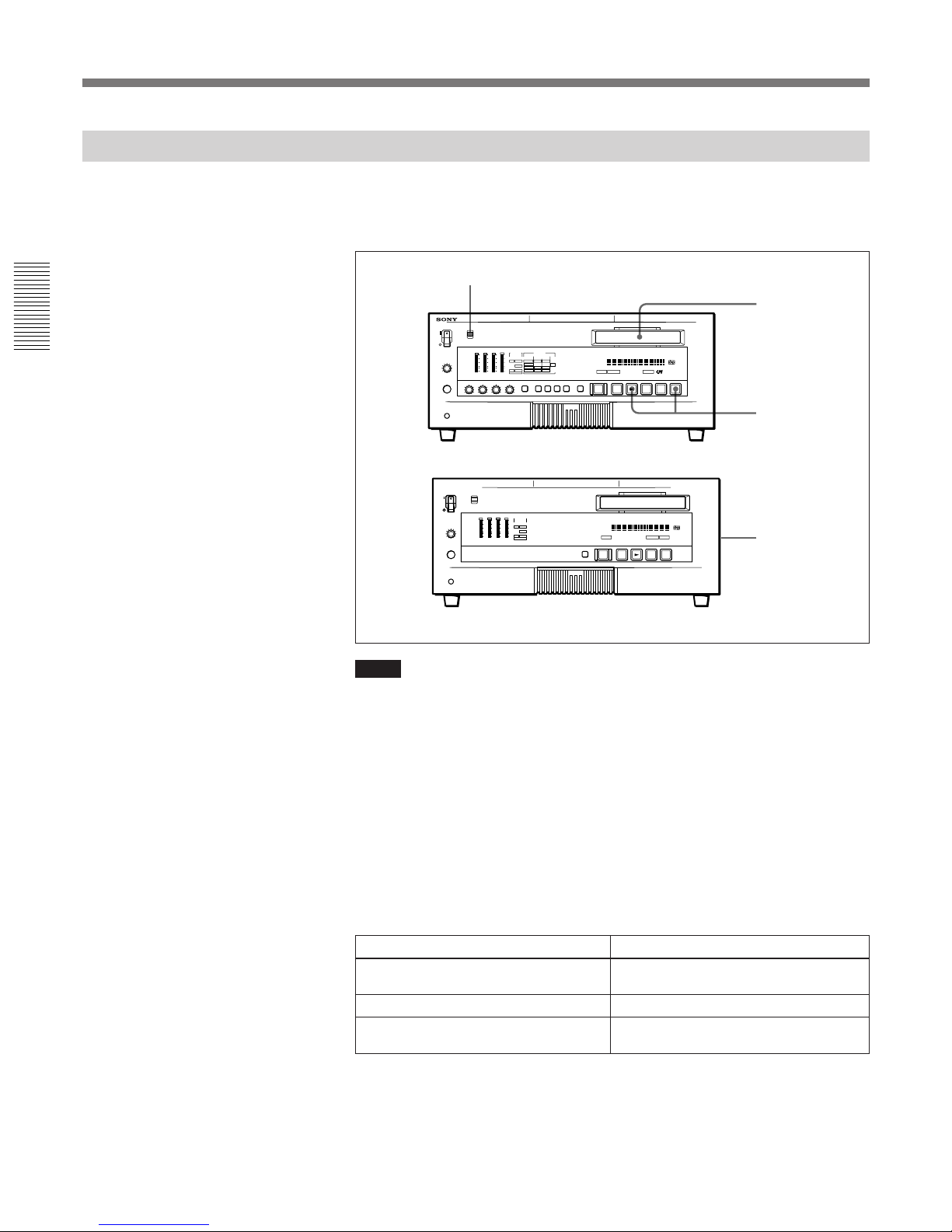
Chapter 1 Overview 11
COUNTER SELECT
EJECT REW PLAY F FWD STOP REC
COUNTER
TC
U-BIT
HOURS MINUTES SECONDS FRAMES
REC INHIBIT
NOT
EDITABLE
REMOTE EDIT MODE
CIip Link
)
0
6
r
p
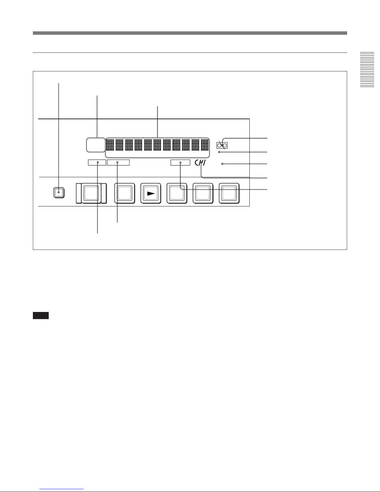
2 Display section (B) and COUNTER SELECT button
3 Time counter display
Indicates the following:
•Time data : CNT (count value of the time counter),
time code, or user bit data
•Digital hours meter’s count value : time total for
unit’s operating hours, drum usage hours, etc.,
(selectable via the digital hours meter display menu).
•Error messages and alarm messages (see page 73)
4 Tape end alarm indicator L
Starts flashing when the tape’s remaining capacity is
for about 2 minutes.
5 REC INHIBIT indicator
Lights when the REC/SAVE switch on the loaded
cassette is in the SAVE position.
6 NOT EDITABLE indicator
Lights during playback of a tape that contains a DVformat recording. DV-format recordings can be used
as source material for editing, but editing functions
such as setting IN/OUT points cannot be used.
This indicator also lights when the audio recording
mode selected on this unit does not coincides with that
of the loaded tape.
1 COUNTER SELECT button
Selects the type of time data to be shown in the time
counter display. Each press of this button cycles
through three indicator display options: COUNTER
(CNT: count value of the time counter), TC (time
code), and U-BIT (user bits).
Note
If the REMOTE/LOCAL switch is set to REMOTE,
the COUNTER SELECT button does not operate
while the tape is moving. In this case, make the time
data selection via the remote equipment that is
connected to the REMOTE connector on the rear
panel.
2 Time data type indicators
One of the three indicators (COUNTER, TC, and UBIT) lights to indicate the type of time data currently
shown in the time counter display.
COUNTER : CNT (count value of the time counter)
TC : SMPTE time code (DSR-80) or EBU time code
(DSR-80P)
U-BIT : User bit data
1 COUNTER SELECT button
2 Time data type indicators
3 Time counter display
9 EDIT MODE indicator
0 REMOTE indicator
8 ClipLink indicator
7 Cassette memory indicator
4 Tape end alarm indicator
5 REC INHIBIT indicator
6 NOT EDITABLE indicator
Features
Chapter 1 Overview
12 Chapter 1 Overview
7 Cassette memory indicator
Lights when a cassette provided with a memory chip
(“cassette memory”) is loaded.
8 ClipLink indicator
Lights when a cassette is loaded on which ClipLink
log data is stored in the cassette memory.
For details of ClipLink log data, refer to the “ClipLink
Guide” also supplied with this unit.
9 EDIT MODE indicator
Lights when this unit is selected as the recorder VCR
under the control of an editing controller connected to
the REMOTE connector on the rear panel of the unit.
0 REMOTE indicator
Lights when the REMOTE/LOCAL switch on the
front panel has been set to REMOTE.
Location and Function of Parts
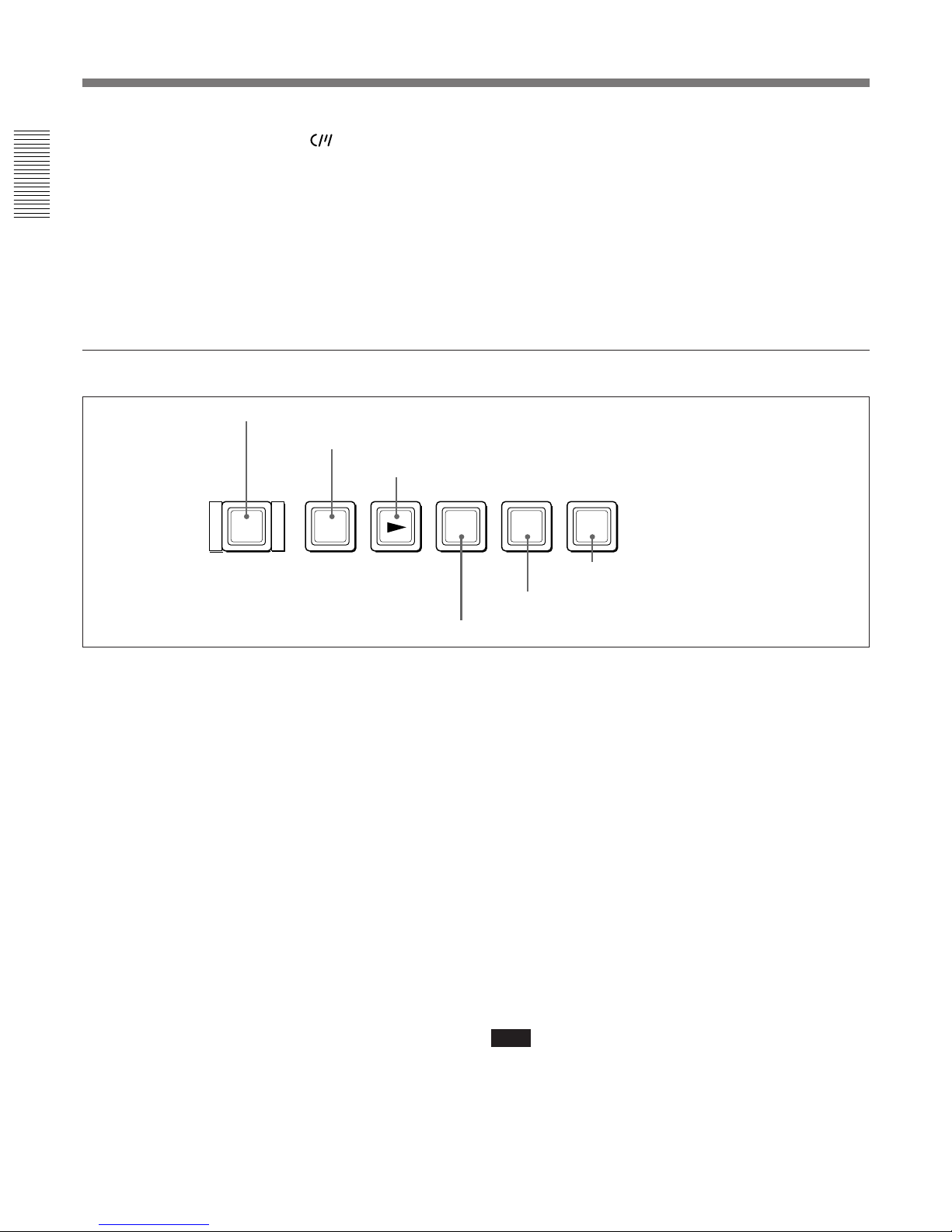
3 Tape transport control section
1 EJECT button
When you press this button, it lights and the cassette is
automatically ejected after a few seconds.
2 REW (rewind) button
When you press this button, it lights and the tape starts
rewinding. During rewind, the picture does not appear
on the monitor.
However, if “F. FWD/REW” under the AUTO EE
SELECT menu item is set to “PB”, holding down the
REW button provides a picture search function at 32
times normal speed in reverse direction.
3 PLAY button
When you press this button, it lights and playback
begins. If you press this button during recording or
editing, the recording or editing operation is stopped
and this unit enters playback mode.
4 F FWD (fast forward) button
When you press this button, it lights and the tape is
fast forwarded. During fast forward, the picture does
not appear on the monitor.
However, if “F. FWD/REW” under the AUTO EE
SELECT menu item is set to “PB”, holding down the F
FWD button provides a picture search function at 32
times normal speed in forward direction.
5 STOP button
Press this button to stop the current tape transport
operation.
6 REC (record) button
When you press this button while holding down the
PLAY button, it lights and recording begins.
Note
A menu setting has been selected at the factory so that
no tape transport control buttons other than EJECT 1
and STOP 5 will work while the REMOTE indicator
is lit on the front panel.
For details on changing menu settings, see “Changing
Menu Settings” (page 51).
EJECT REW PLAY F FWD STOP REC
)
0
6
r
p
1 EJECT button
4 F FWD button
2 REW button
3 PLAY button
5 STOP button
6 REC button
Chapter 1 Overview
Chapter 1 Overview 13
SYNC PHASE SC PHASE MENU
TC PRESET
MONITOR SELECT
RESET(NO)
SET(YES)
CH1/2
CH3/4
CH-
1/3
CH2/4
MIX
PUSH OPEN
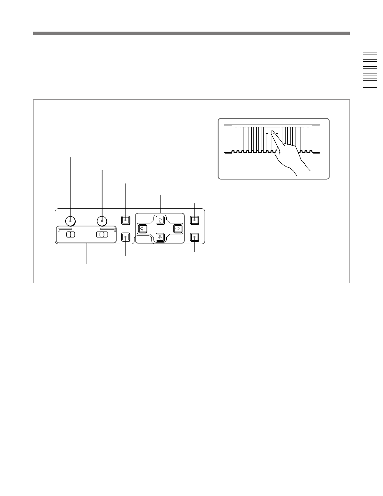
4 Menu control panel
The menu control panel is located on the inside of the
door at the lower front of the unit. Press on the top of
the door to open it.
For details on setting time code and user bit data, see
“Using the Internal Time Code Generator” (page 33).
5 RESET (NO) button
Press this button to:
•reset menu settings,
•reset the time data shown in the time counter display
to zero, or
•send a negative response to the unit’s prompts.
6 SET (YES) button
Press this button to:
•save new settings, such as selected menu items and
time code settings, to the unit’s memory, or
•send a positive response to the unit’s prompts.
7 TC (time code) PRESET button
Use this button when setting time code’s initial values
and user bit data.
For details on setting time code and user bit data, see
“Using the Internal Time Code Generator” (page 33).
1 SYNC (synchronization) PHASE control
Turn this control to accurately adjust the
synchronization phase of the output video signal of the
unit with respect to the reference video signal. Use a
cross-point (Phillips) screwdriver to turn it.
2 SC (subcarrier) PHASE control
Turn this control to accurately adjust the subcarrier
phase of the composite video output signal of the unit
with respect to the reference video signal. Use a crosspoint (Phillips) screwdriver to turn it.
3 MENU button
Press this button to display the menu on the monitor
screen and the time counter display. Press it again to
return from the menu display to the usual display.
On how to use the menu, see chapter 4 “Menu Settings”.
4 Arrow (˘ ≥ ¿ ÷) buttons
Use these buttons to move around the menu items, and
also for setting time code and user bit data.
2 SC PHASE control
3 MENU button
4 Arrow buttons
5 RESET (NO) button
7 TC PRESET button
6 SET (YES) button
1 SYNC PHASE control
To expose the menu control panel
Press on the
top of the door.
8 MONITOR SELECT switches
Features
Chapter 1 Overview
14 Chapter 1 Overview
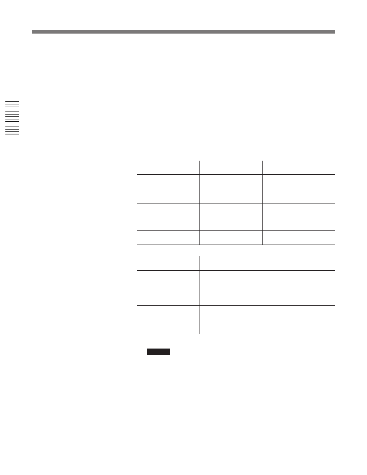
8 MONITOR SELECT switches
Use these switches to select the channels for audio
output via the MONITOR AUDIO connector on the
rear panel and the HEADPHONES connector on the
front panel.
Use the left switch to select the basic channel setting,
then use the right switch to select the output format
(monaural, stereo, or mix).
The table at right lists the correspondence of left/right
switch settings and channel/output format selections.
Switch setting Selected channel and output format
Left
switch
Right
switch
HEADPHONES
connector
MONITOR AUDIO
connector
Channel 1 only
(monaural)
Channel 1 only
(monaural)
Channels 1 and 2
(stereo)
Channels 1 and 2
(mix)
Channel 2 only
(monaural)
Channel 2 only
(monaural)
Channel 3 only
(monaural)
Channel 3 only
(monaural)
Channels 3 and 4
(stereo)
Channels 3 and 4
(mix)
Channel 4 only
(monaural)
Channel 4 only
(monaural)
CH-
1/2
CH3/4
CH1/2
CH-
3/4
CH-
1/3
CH2/4
MIX
CH-
1/3
CH2/4
MIX
CH-
1/3
CH2/4
MIX
CH-
1/3
CH2/4
MIX
CH-
1/3
CH2/4
MIX
CH-
1/3
CH2/4
MIX
Location and Function of Parts
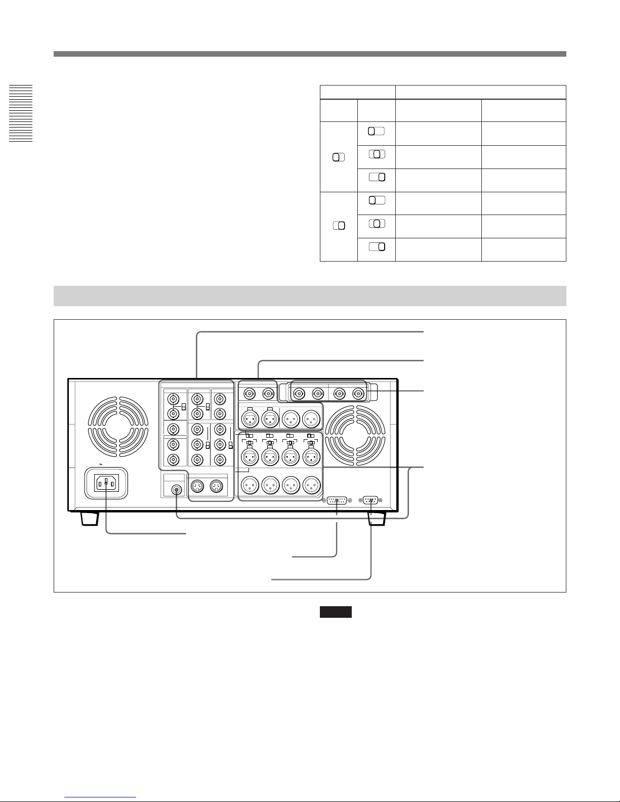
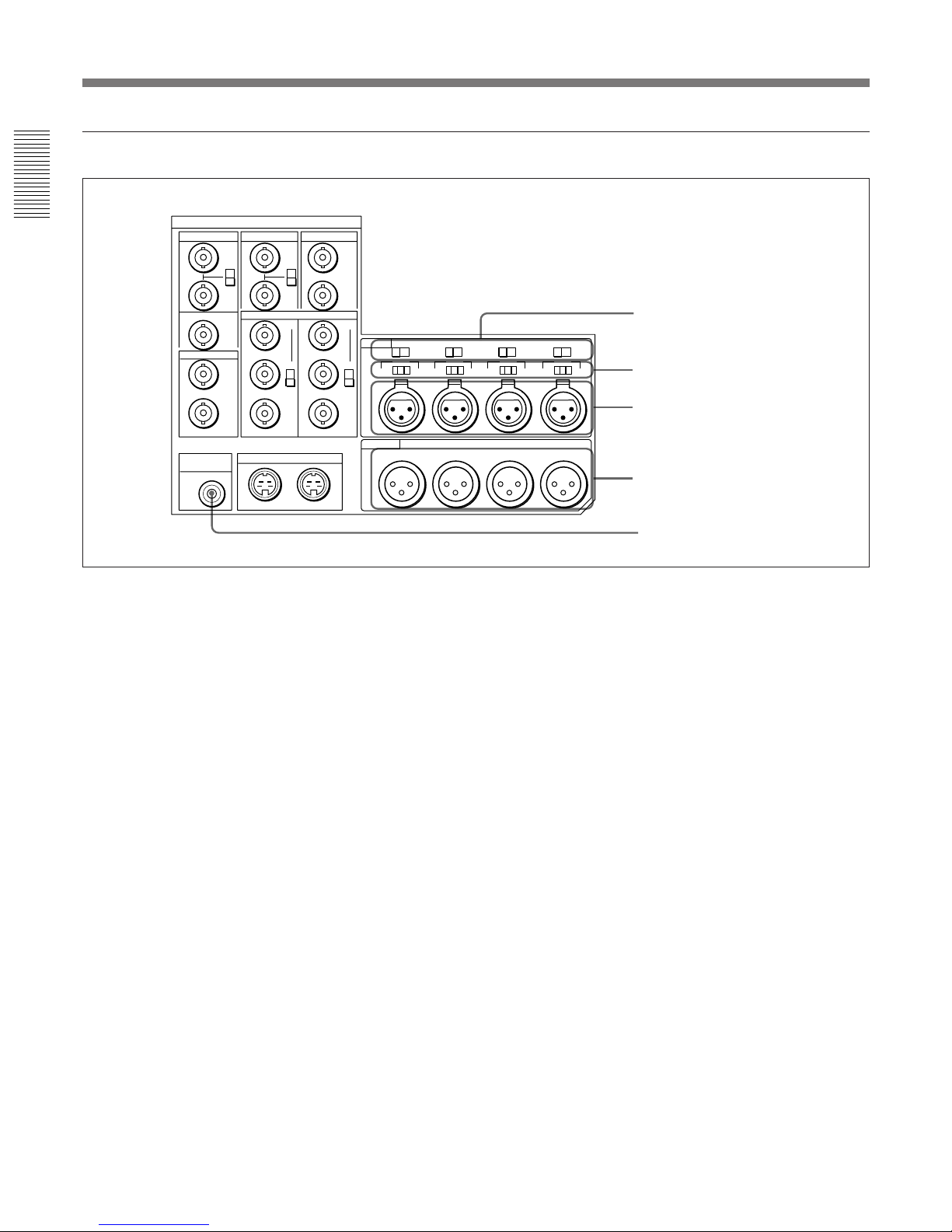
REMOTE
AC IN
ANALOG I/O
REF.VIDEO
TIME CODE
VIDEO IN VIDEO OUT
MONITOR
AUDIO
S VIDEO
QSDI
DIGITAL AUDIO (AES/EBU)
COMPONENT VIDEO
TBC REMOTE
SDI INPUT SDI OUTPUT
Rear Panel
1 AC IN connector
Connect to an AC power outlet using the supplied
power cord.
2 TBC (time base corrector) REMOTE connector
(15-pin)
To remote-control the built-in time base corrector,
connect an optional TBC remote controller such as the
UVR-60/60P, BK-2006/2007 or BVR-50/50P.
1 AC IN connector
2 TBC REMOTE connector
3 REMOTE connector
Notes
•Be sure to power off this unit before connecting the
TBC remote controller to the TBC REMOTE
connector.
•TBC remote control can be applied only to the analog
video outputs from the VIDEO OUT 1 and 2
(SUPER) connectors 6, COMPONENT VIDEO Y,
R–Y, and B–Y/RGB OUT connectors 8, and S
VIDEO OUT connector 0 in the analog video signal
input/output section
1 on the next page.
1 Analog video signal input/
output section (see page 15)
2 Digital signal input/output
section (see page 16)
3 SDI signal input/output
section (with the optional
DSBK-120/120P installed)
(see page 17)
4 Analog audio signal input/
output section (see page 18)

Chapter 1 Overview
Chapter 1 Overview 15
1 Analog video signal input/output section
1 REF. (reference) VIDEO IN (input) connectors
(BNC type) and 75 Ω termination switch
Input a reference video signal to one of these
connectors. The two connectors can be used for a
loop-through connection. When making a loopthrough connection, set the 75 Ω termination switch to
OFF and when not, set the switch to ON.
When using the COMPONENT VIDEO Y, R–Y, and
B–Y/RGB IN connectors 7 in four-wire mode (with
no sync signal included in the green signal), input a
sync signal to this connector.
2 REF. (reference) VIDEO OUT (output)
connector (BNC type)
Outputs a reference video signal.
When using the COMPONENT VIDEO Y, R–Y, and
B–Y/RGB OUT connectors 8 in four-wire mode
(with no sync signal included in the green signal), this
connector outputs a sync signal.
3 TIME CODE IN connector (BNC type)
Input SMPTE time code (DSR-80) or EBU time code
(DSR-80P) externally generated.
4 TIME CODE OUT connector (BNC type)
When the unit is in normal-speed playback mode, this
connector outputs the time code read from the tape as
an analog (LTC) signal. When the unit is in any other
mode, the connector outputs no signal.
Note
The TIME CODE IN connector 3 and TIME CODE
OUT connector 4 can only be used when an optional
DSBK-130/130P Time Code Input/Output Board is
installed in this unit.
5 VIDEO IN connectors (BNC type) and 75 Ω
termination switch
Input a composite video signal to one of these
connectors. The two connectors can be used for a
loop-through connection. When making a loopthrough connection, set the 75 Ω termination switch to
OFF and when not, set the switch to ON.
ANALOG I/O
REF.VIDEO
IN
75Ω
ON
OFF
OUT
IN
OUT
TIME CODE
VIDEO IN
75Ω
ON
OFF
Y-R,B
RGB
Y-R,B
RGB
VIDEO OUT
1
2
(SUPER)
YIN
G
R-Y
R
B-Y
B
Y
G
R-Y
R
B-Y
B
MONITOR
AUDIO
OUTIN
S VIDEO
COMPONENT VIDEO R.G.B.
OUT
5 VIDEO IN connectors and 75 Ω termination
switch
6 VIDEO OUT 1 and 2 (SUPER) connectors
7 COMPONENT VIDEO Y, R–Y, B–Y/RGB IN
connectors
8 COMPONENT VIDEO Y, R–Y, B–Y/RGB
OUT connectors
9 S VIDEO IN connector
0 S VIDEO OUT connector
1 REF. VIDEO IN connectors
and 75 Ω termination switch
3 TIME CODE IN connector
4 TIME CODE OUT connector
2 REF. VIDEO OUT connector
3 REMOTE connector (9-pin)
When controlling this unit from an editing controller
such as the ES-7, PVE-500, BVE-600/800/910, or
RM-450/450CE, connect the unit to the editing
controller via this connector using the supplied 9-pin
remote control cable.
Features
Chapter 1 Overview
16 Chapter 1 Overview
QSDI
INPUT OUTPUT
DIGITAL AUDIO (AES/EBU)
CH-1/2 CH-3/4
INPUT OUTPUT
CH-1/2 CH-3/4
2 Digital signal input/output section
6 VIDEO OUT 1 and 2 (SUPER) connectors (BNC
type)
Output a composite video signal. When “CHARA.
DISPLAY” under the DISPLAY CONTROL menu
item has been set to “ON” (factory default setting), a
character signal is superimposed on the video signal
that is output from the VIDEO OUT 2 (SUPER)
connector.
7 COMPONENT VIDEO Y, R–Y, B–Y/RGB IN
connectors (BNC type)
Input a component video (Y, R–Y, B–Y) signal or
RGB signal, according to the setting of the selector
switch.
Y : Luminance signal
R–Y and B–Y : Color difference signals
8 COMPONENT VIDEO Y, R–Y, B–Y/RGB OUT
connectors (BNC type)
Output a component video (Y, R–Y, B–Y) signal or
RGB signal, according to the setting of the selector
switch. The RGB signal may also have a sync signal
included in the green signal, according to a menu
setting.
Y : Luminance signal
R–Y and B–Y : Color difference signals
For details, see the menu item VIDEO CONTROL, setting
“SYNC ON GREEN”. (Page 47)
9 S VIDEO IN connector (4-pin)
Input an S-video signal with separated Y (luminance)
and C (chroma: 3.58 MHz for DSR-80 and 4.43 MHz
for DSR-80P) components.
0 S VIDEO OUT connector (4-pin)
Outputs an S-video signal with separated Y
(luminance) and C (chroma: 3.58 MHz with DSR-80
and 4.43 MHz with DSR-80P) components.
Location and Function of Parts
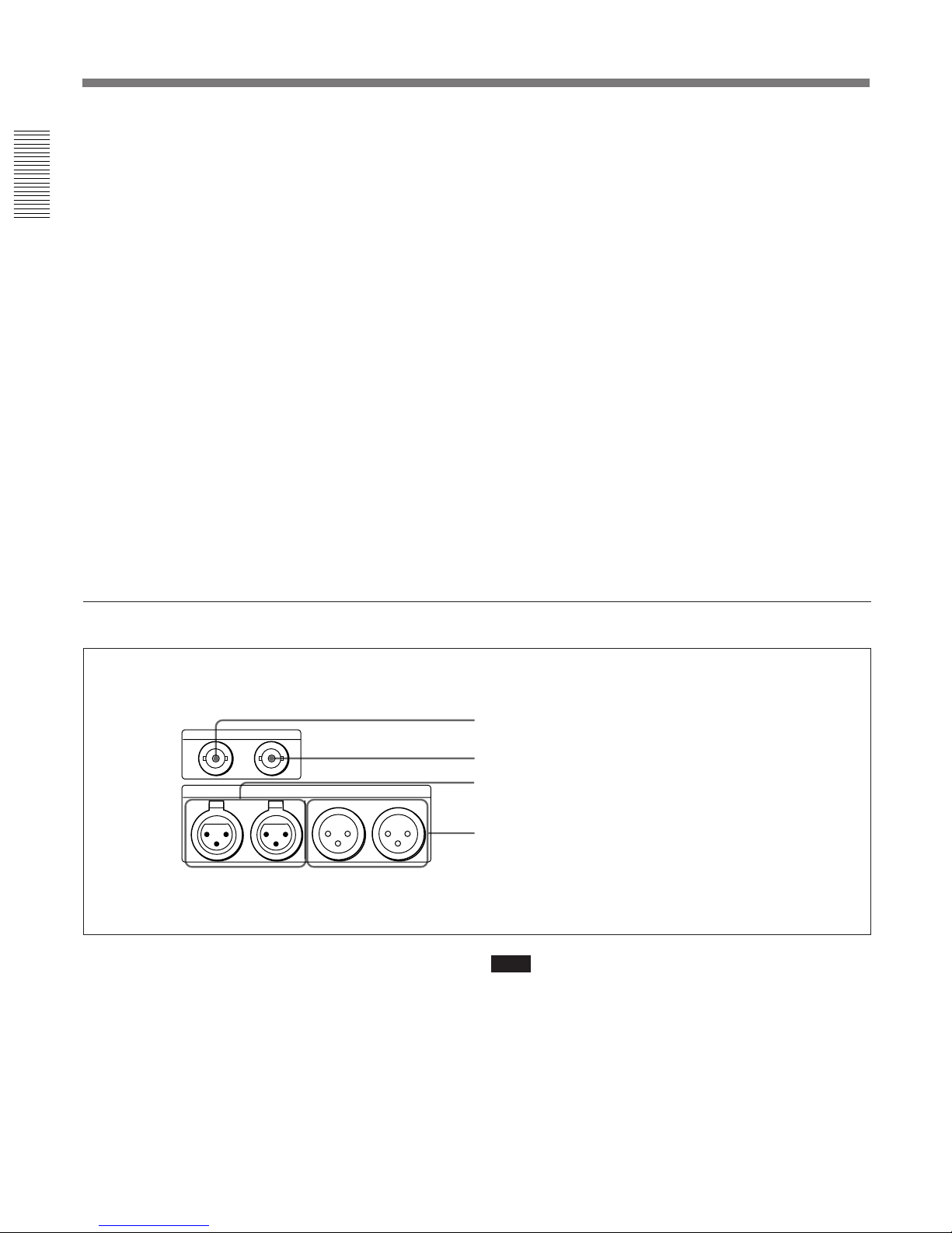
1 QSDI INPUT connector (BNC type)
Input video, audio and time code signals in the QSDI
format.
2 QSDI OUTPUT connector (BNC type)
Outputs video, audio and time code signals in the
QSDI format when the unit is in playback mode, but
outputs no EE signals.
1 QSDI INPUT connector
2 QSDI OUTPUT connector
3 DIGITAL AUDIO (AES/EBU) INPUT connectors
4 DIGITAL AUDIO (AES/EBU) OUTPUT connectors
Note
In search mode, this connector outputs unprocessed
audio signals. If you are monitoring this audio signal
on another device, the sound may be different from the
playback output of this unit.
3 DIGITAL AUDIO (AES/EBU) INPUT
connectors (XLR 3-pin, female)
Input digital audio signals in the AES/EBU format.

Chapter 1 Overview
Chapter 1 Overview 17
3 SDI (Serial Digital Interface) signal input/output section (with the optional DSBK-120/
120P installed)
When an optional DSBK-120/120P SDI Input/Output
Board is installed in the unit, this section can be used
for inputting and outputting SDI signals.
SDI INPUT SDI OUTPUT
1 SDI INPUT connector and active through output connector
2 SDI OUTPUT connectors
1 SDI (Serial Digital Interface signal) INPUT
connector and active through output connector
(BNC type)
The left connector is for input of SDI-format digital
video and audio signals. The right connector can be
used as an active through output connector.
2 SDI (Serial Digital Interface signal) OUTPUT
connectors (BNC type)
Output SDI-format digital video and audio signals.
The same signals are output from both connectors.
4 DIGITAL AUDIO (AES/EBU) OUTPUT
connectors (XLR 3-pin, male)
Output digital audio signals in the AES/EBU format.
Features
Chapter 1 Overview
18 Chapter 1 Overview
CH-1
AUDIO IN
600Ω
OFF ON
0dBm
-8dBm +4dBm
CH-2
600Ω
0dBm
-8dBm +4dBm
CH-3
600Ω
0dBm
-8dBm +4dBm
CH-4
600Ω
0dBm
-8dBm +4dBm
AUDIO OUT
CH-1 CH-2 CH-3 CH-4
OFF ON OFF ON OFF ON
ANALOG I/O
REF.VIDEO
IN
75Ω
ON
OFF
OUT
IN
OUT
TIME CODE
VIDEO IN
75Ω
ON
OFF
Y-R,B
RGB
Y-R,B
RGB
VIDEO OUT
1
2
(SUPER)
YIN
G
R-Y
R
B-Y
B
Y
G
R-Y
R
B-Y
B
MONITOR
AUDIO
OUTIN
S VIDEO
COMPONENT VIDEO R.G.B.
OUT
4 Analog audio signal input/output section
Location and Function of Parts
1 AUDIO IN 600 Ω ON/OFF switches
Use these switches to select either 600 Ω impedance
(the ON setting) or 10-kΩ impedance (the OFF setting)
for the AUDIO IN CH-1 to CH-4 connectors.
2 AUDIO IN –6 dBm/0 dBm/+4 dBm switches
Set these switches according to the levels of the signals
input to the AUDIO IN CH-1 to CH-4 connectors.
3 AUDIO IN CH-1 (channel 1) to CH-4 connectors
(XLR 3-pin, female)
Use these connectors to connect separate channels of
audio input from a player VCR or other external audio
equipment.
4 AUDIO OUT CH-1 (channel 1) to CH-4
connectors (XLR 3-pin, male)
Output channel-1 to channel-4 audio signals,
respectively.
5 MONITOR AUDIO connector (RCA phono
jack)
Outputs audio signals for monitoring. The audio
signals to be output from this connector can be
selected with the MONITOR SELECT switches on the
menu control panel 4 (see page 13).
1 AUDIO IN 600 Ω ON/OFF switches
2 AUDIO IN –6 dBm/0 dBm/+4 dBm
switches
3 AUDIO IN CH-1 to CH-4 connectors
4 AUDIO OUT CH-1 to CH-4
connectors
5 MONITOR AUDIO connector
Chapter 2 Recording and Playback
Chapter 2 Recording and Playback 19
Recording
This section describes the necessary settings and operations to perform
recording on this unit. The same settings and operations apply whether
you are using the unit as part of an editing system, for dubbing
1)
, or as a
stand-alone recorder. For the necessary connections for recording and the
settings not covered in this section, see Chapter 5 “Connections and
Settings”.
Settings for Recording
Note
When controlling this unit from an editing controller, set the REMOTE/
LOCAL switch to “REMOTE”. When not, set the switch to “LOCAL”.
1 Power on the video monitor, then set the monitor’s input switches
according to the input signals from this unit.
2 Set up the player to play back a tape.
For details, refer to your player’s operating instructions.
3 Power on this unit by pressing on the “1” side of the POWER switch.
Chapter 2 Recording and Playback
)
0
6
r
p
3
7 654
12
)
0
6
p
INPUT MODE display
AUDIO MODE display
Audio level meter
Video monitor Player (DSR-60/60P, etc.)
Recorder (DSR-80/80P)
REMOTE/LOCAL
switch
(Continued)
........................................................................................................................................................................................................
1) For dubbing of QSDI format signals, use the auto mode
(AUTO FUNCTION) execution menu item QSDI
DUBBING.
For details, see the section “Dubbing Signals in QSDI
Format” on page 38.
Recording
Chapter 2 Recording and Playback
20 Chapter 2 Recording and Playback
4 When the REMOTE/LOCAL switch is set to “LOCAL”, use the
COUNTER SELECT button to select the type of time data to be used.
Each press of this button cycles through three options : COUNTER
(CNT value), TC (time code), and U-BIT (user bit data). The time
data type indicator for each option lights as it is selected.
When the REMOTE/LOCAL switch is set to “REMOTE”, selection of
the time data type is carried out at the editing controller.
5 Select the formats of video and audio input signal to be recorded.
Press INPUT SELECT buttons to select the desired signal formats.
Each selection is shown by a lit indicator in the INPUT MODE
display.
Caution
Once you have started recording, you cannot change the input signal
selection.
QSDI
Video input signal
(input connector)
Corresponding INPUT
SELECT button
Lit indicator in INPUT
MODE display
VIDEO COMPOSITE in VIDEO
group
Separated Y/C signal
(S VIDEO IN)
VIDEO S VIDEO in VIDEO group
Composite signal
(VIDEO IN)
Component signal
(COMPONENT VIDEO
IN)
VIDEO COMPONENT in VIDEO
group
SDI signal (SDI INPUT) VIDEO SDI in VIDEO group
QSDI signal (QSDI
INPUT)
QSDI QSDI
Audio input signal
(input connector)
AUDIO CH-1 CH-1/2,
AUDIO CH-2 CH-3/4
QSDI signal (QSDI
INPUT)
Corresponding INPUT
SELECT button
Lit indicator in INPUT
MODE display
Analog signal (AUDIO
IN CH-1 to CH-4)
ANALOG in AUDIO group
AES/EBU signal
(DIGITAL AUDIO
(AES/EBU) INPUT)
AUDIO CH-1 CH-1/2,
AUDIO CH-2 CH-3/4
AES/EBU in AUDIO group
SDI signal (SDI INPUT) AUDIO CH-1 CH-1/2,
AUDIO CH-2 CH-3/4
SDI in AUDIO group
QSDI

Chapter 2 Recording and Playback
Chapter 2 Recording and Playback 21
6 Select the audio mode.
Press the AUDIO REC SELECT button to select the desired mode.
Each selection is shown by lit indicators in the AUDIO MODE
display.
Cautions
•In the DVCAM format, there are two audio recording modes, with
either two channels at 48 kHz or four channels at 32 kHz. It is not
possible to select other modes (for example with four channels at 48
kHz).
•During editing, if a signal used in assemble or insert editing is in a
different mode from the base tape, the signals will be discontinuous at
the edit points, and correct editing will not be obtained. For this
reason, audio editing between different modes is inhibited on this
unit.
For smooth editing operations, check the audio recording mode of the
base tape beforehand.
•The audio mode selecting operation is only possible when the unit is
in EE mode.
•Once you have started recording, you cannot change the audio mode
selection.
•If on a tape there is a point where the audio mode is switched, you
cannot perform an insert editing on that tape.
7 Use the AUDIO INPUT LEVEL control knobs to adjust audio input
levels.
Watching the audio level meter, adjust the level so that the meter does
not indicate higher values than 0 dB when the audio signal is at its
maximum.
When the level exceeds 0 dB, the OVER indicator lights.
The factory-preset audio recording level is –20 dB (DSR-80) or
–18 dB (DSR-80P). This setting can be changed to –12 dB using the
AUDIO CONTROL menu item.
On how to use the menu, see Chapter 4 “Menu Settings”.
Audio mode Lit indicator in AUDIO MODE display
2-channel mode 2CH and Fs48k
4-channel mode 4CH and Fs32k

Recording
Chapter 2 Recording and Playback
22 Chapter 2 Recording and Playback
Usable Cassettes
This unit can use standard-size and mini-size DVCAM cassettes listed
below.
The numbers in each model name indicate the maximum recording/
playback time (in minutes) for each model. For example, the PDV-184ME
has a maximum recording/playback time of 184 minutes.
Notes
•If you insert an incorrect type of cassette, it will be automatically ejected.
•When operating this unit as a player, you can also use DV cassettes on
the unit. However, it is the best choice to always use DVCAM cassettes
because they are more reliable than DV cassettes whatever your purpose
may be: playback, editing, or long-period storage of recordings.
•Cassettes that have been recorded by a DV-format recorder can be played
back on this unit but cannot be used for recording at editing operation
such as the setting of edit points. When you insert such a cassette into
this unit, the NOT EDITABLE indicator lights up on the front panel of
the unit.
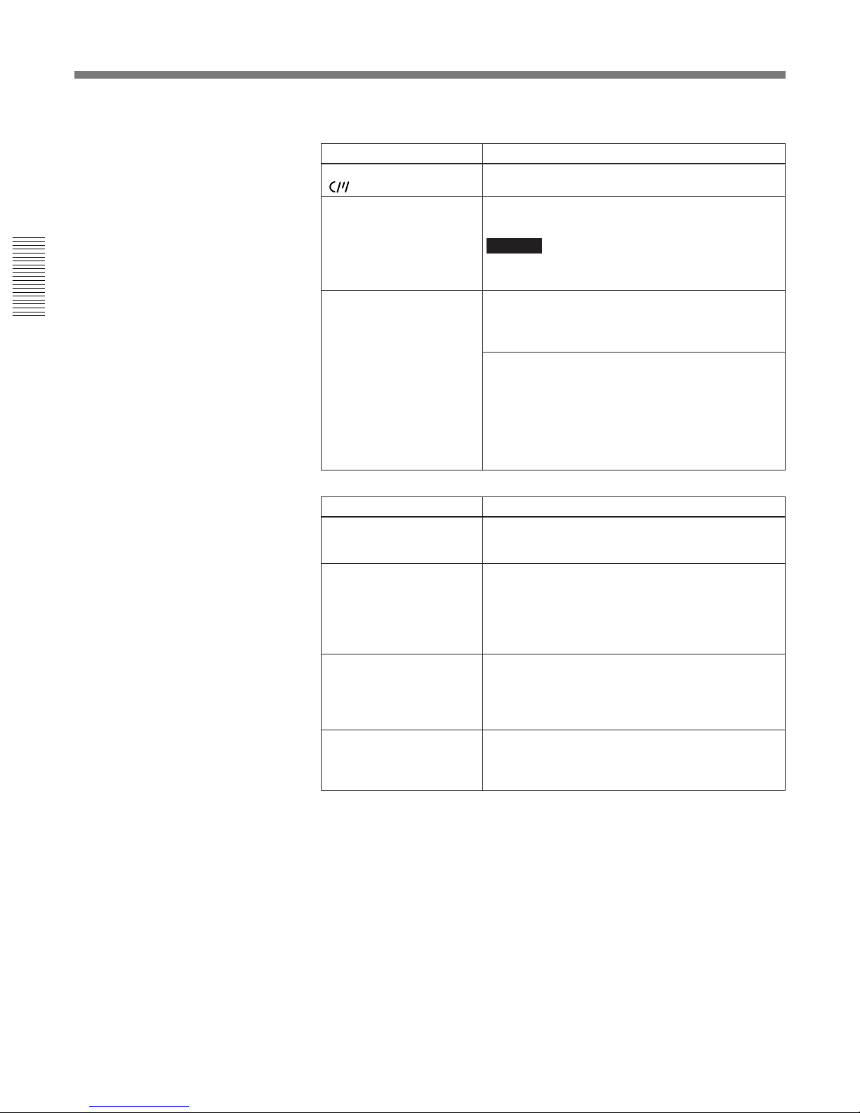
DVCAM cassettes
The following figure illustrates the DVCAM cassette’s appearance.
Model name Size
PDV-64ME/94ME/124ME/184ME Standard size
PDVM-12ME/22ME/32ME/40ME Mini size
Mini size
Cassette memory
This memory is used to store ClipLink
log data. For details of ClipLink log data,
refer to “ClipLink Guide” supplied with
this unit.
REC/SAVE switch
For details of this switch, see
“Preventing accidental erasure”
(page 27).
Standard size

Chapter 2 Recording and Playback
Chapter 2 Recording and Playback 23
Notes on using cassettes
•Before storing the cassette, rewind the tape to the beginning and be sure
to put the cassette in its storage case, preferably on end instead of flat on
its side. The storage case of a DVCAM cassette is specially designed to
ensure a long-period storage of the tape.
Storing a cassette in any other condition (not rewound, out of its case,
etc.) may cause the video and audio contents to become damaged over
time.
•If the cassette memory connector (contact point) becomes dirty,
connection problems may occur and cause a loss of functions. Remove
away any dust or dirt from this area before using the cassette.
•If the cassette is dropped on the floor or otherwise receives a hard impact,
the tape may become slackened and may not record and/or play back
correctly.
For instructions on removing tape slack, see page 27.
Recording
Chapter 2 Recording and Playback
24 Chapter 2 Recording and Playback
Recording Procedure
This section describes the procedure to perform a recording on this unit,
showing an example session in which playback signals coming from a
player VCR will be recorded on the tape loaded in the unit.
Notes
•When controlling this unit from an editing controller, set the REMOTE/
LOCAL switch to “REMOTE”. When not, set the switch to “LOCAL”.
•If you intend to use a tape recorded on this unit in a system comprising a
DSR-85/85P and an ES-7 EditStation, it is recommended to record color
bars on at least the first 40 seconds of the tape.
When transferring digital signals from the DSR-85/85P to the ES-7
EditStation at quadruple speed, there must be recording for
approximately 40 seconds before the IN point.
1 After checking the following items, hold the cassette so that the tape
window is facing upward, then insert it into the recorder (this unit) as
illustrated on the next page.
)
0
6
r
p
1
2
3
)
0
6
p
Recorder (DSR-80/80P)
REMOTE/LOCAL switch
Player (DSR-60/60P, etc.)
Item to check
See section
Make sure that the cassette’s “REC/
SAVE” switch is set to “REC”.
“Preventing accidental erasure” (page
27).
Check for tape slack.
“Checking the tape for slack” (page 27).
“Condensation” (page 69)Make sure that the “HUMID!” alarm is
not shown in the display window.

Chapter 2 Recording and Playback
Chapter 2 Recording and Playback 25
The cassette is automatically drawn into the unit and the tape is wound
round the head drum. The tape is stationary while the head drum
rotates, and the STOP button lights.
If the REC INHIBIT indicator lights:
It indicates that the loaded cassette’s REC/SAVE switch has been set
to SAVE. Press the EJECT button in the tape transport control section
to remove the cassette, then set the cassette’s REC/SAVE switch to
REC and reload the cassette.
Note
Make sure that the unit’s power is on when ejecting and loading
cassettes.
2 Press and hold the REC button, and press the PLAY button.
This puts the unit into recording mode, and the tape starts moving.
3 Press the PLAY button on the player.
This starts the player’s playback operation, at which point this unit
starts recording the input playback signals.
Cautions
•Once you have started recording, you cannot change the audio mode
selection.
•If on a tape there is a point where the audio mode is switched, you cannot
perform an insert editing on that tape.
Standard size
Tape window facing upward
Mini size
Insert the mini-size cassette into
the middle of the cassette
compartment.
Recording
Chapter 2 Recording and Playback
26 Chapter 2 Recording and Playback
If the following indicators light when a cassette is loaded
The loaded cassette contains a cassette memory.
Indicator It means:
Cassette memory indicator
ClipLink indicator There is ClipLink log data stored in the cassette
memory on the loaded cassette.
Caution
With such a cassette, execution of recording may
destroy the ClipLink log data.
NOT EDITABLE indicator The recording format of the tape is “DV”.
Replace the tape with one that has been recorded in
“DVCAM” format when the unit is a recorder for
editing.
The audio recording mode selected on this unit does
not coincides with that of the tape.
• When your current purpose is recording, you can
use the tape as it is.
• When your current purpose is editing, set the unit
for the same audio recording mode as with the
tape.
(For more details, see “Troubleshooting”
(page 71.)
For this purpose:
Do this:
Stop recording Press the STOP button.
The unit enters stop mode, and will automatically
switch to standby off mode after 8 minutes.
Remove the cassette Press the EJECT button.
After a few seconds, the tape is unwound from the
head drum and the cassette is automatically ejected.
If a CNT value is shown on the time counter display
(assuming the time data type indicator “COUNTER”
is lit), the CNT value is reset.
Inhibit the unit from
outputting text information
(time data, operation mode
indications, etc.) to the
video monitor.
Change the menu settings.
See “CHARA. DISPLAY” (page 43) in Chapter 4
“Menu Settings”.
Change the time period
before the unit switches to
standby off mode from stop
mode
Change the menu settings.
See “TAPE PROTECTION” (page 46) in Chapter 4
“Menu Settings”.
Chapter 2 Recording and Playback
Chapter 2 Recording and Playback 27
Preventing accidental erasure
Set the REC/SAVE switch on the cassette to SAVE to prevent accidental
erasure of recorded contents.
To enable re-recording
Set the cassette’s REC/SAVE switch to REC.
If you insert a cassette into the unit when this switch is set to SAVE, the
unit will not record when you press the PLAY button while holding down
the REC button.
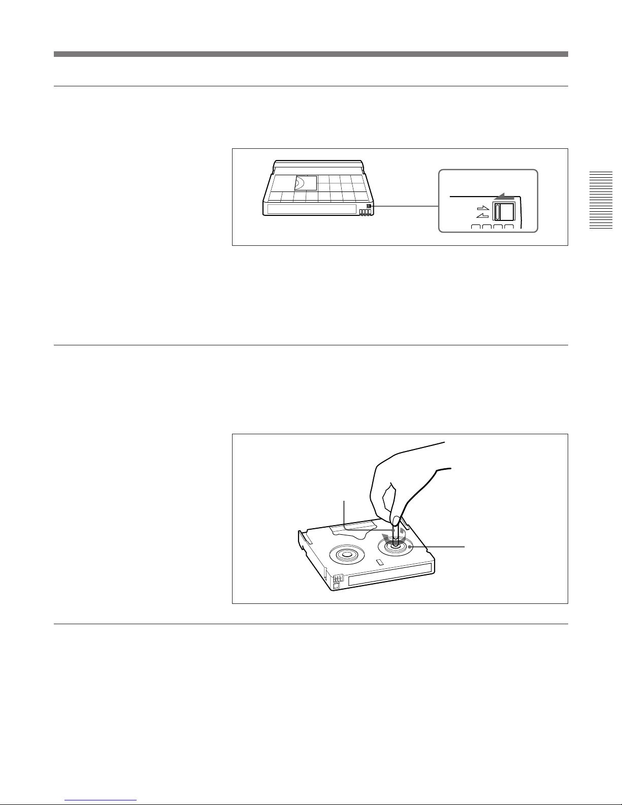
Checking the tape for slack
Using a paper clip or a similar object, turn the reel gently in the direction
shown by the arrow. If the reel does not move, there is no slack. Insert the
cassette into the cassette compartment, and after about 10 seconds take it
out.
No double insertion of cassettes
When you insert a cassette, the orange lock-out plate appears in the
cassette compartment to prevent double insertion.
Reel
Paper clip, etc.
REC
SAVE
Set to SAVE
REC/SAVE switch
 Loading...