

Sony DVCAM DSR-300AK, DVCAM DSR-300AL, DVCAM DSR-300APK, DVCAM DSR-300APL Operating Instructions Manual
3-203-818-12(1)
Digital Camcor der
Operating Instructions
Before operating the unit, please read this manual
thoroughly and retain it for future reference.
DSR-300AK/300APK
DSR-300AL/300APL
2000 by Sony Corporation

WARNING
To prevent fire or shock hazard, do not
expose the unit to rain or moisture.
VARNING
Explosionsfara vid felaktigt batteribyte.
Använd samma batterityp eller en likvärdig typ som
rekommenderas av apparattillverkaren.
Kassera använt batteri enligt gällande föreskrifter.
To avoid electrical shock, do not open
the cabinet. Refer servicing to qualified
personnel only.
Owner’s Record
The model and serial numbers are located on the top.
Record these numbers in the spaces provided below. Refer
to them whenever you call upon your Sony dealer regarding
this product.
Model No.
LITHIUM BATTERY
Replace the battery with a Sony CR2032 lithium battery.
Use of another battery may present a risk of fire or
explosion.
WARNING
Battery may explode if mistreated.
Do not recharge, disassemble or dispose of in fire.
Note
Keep the lithium battery out of the reach of children.
Should the battery be swallowed, consult a doctor
immediately.
Lithiumbatteri - Eksplosionsfare ved fejlagtig håndtering.
Udskiftning må kun ske med batteri af samme fabrikat og
Serial No.
ADVARSEL!
type.
Levér det brugte batteri tilbage til laverandøren.
ADVARSEL
Lithiumbatteri - Eksplosjonsfare.
Ved utskifting benyttes kun batteri som anbefalt av
apparatfabrikanten.
Brukt batteri returneres apparatleverandøren.
VAROITUS
Paristo voi räjähtää jos se on virheellisesti asennettu.
Vaihda paristo ainoastaan laitevalmistajan
suosittelemaan tyyppiin.
Hävitä käytetty paristo valmistajan ohjeiden mukaisesti.
For customers in the USA
This equipment has been tested and found to comply with
the limits for a Class A digital device, pursuant to Part 15
of the FCC Rules. These limits are designed to provide
reasonable protection against harmful interference when
the equipment is operated in a commercial environment.
This equipment generates, uses, and can radiate radio
frequency energy and, if not installed and used in
accordance with the instruction manual, may cause
harmful interference to radio communications. Operation
of this equipment in a residential area is likely to cause
harmful interference in which case the user will be
required to correct the interference at his own expense.
You are cautioned that any changes or modifications not
expressly approved in this manual could void your
authority to operate this equipment.
The shielded interface cable recommended in this manual
must be used with this equipment in order to comply with
the limits for a digital device pursuant to Subpart B of Part
15 of FCC Rules.
For the customers in Europe
This product with the CE marking complies with the EMC
Directive (89/336/EEC) issued by the Commission of the
European Community.
Compliance with this directive implies conformity to the
following European standards:
• EN55103-1: Electromagnetic Interference (Emission)
• EN55103-2: Electromagnetic Susceptibility (Immunity)
This product is intended for use in the following
Electromagnetic Environment(s):
E1 (residential), E2 (commercial and light industrial), E3
(urban outdoors) and E4 (controlled EMC environment,
ex. TV studio).

Table of Contents
Chapter 1
Overview
Chapter 2
Fitting and
Connections
Product Configurations ....................................................7
Features .............................................................................8
Features on Camera Section ................................................ 8
Features on VCR Section .................................................... 9
Location and Function of Parts ..................................... 12
Front Vie w ......................................................................... 12
Right Side View................................................................. 13
Left and Upper View ......................................................... 23
Rear and Bottom................................................................ 25
VCL-718BX Zoom Lens................................................... 27
DXF-801/801CE Vie wfinder............................................. 29
IInserting and Replacing the Lithium Battery ..............31
Fitting the Lens ...............................................................33
Using Accessories ..........................................................35
Using the Viewfinder......................................................... 35
Fitting the 4-inch/5-inch Electronic Viewfinder................ 36
Fitting to a Tripod.............................................................. 36
Using an Optional Microphone ......................................... 37
Using a Video Light........................................................... 38
Fitting the Shoulder Strap ................................................. 39
Connecting to Audio System............................................. 40
Using the RM-LG1 Remote Control Unit......................... 42
Using the Optional RM-VJ1 Remote Control Unit
(Equipped With Microphone And Monitor)................. 43
Using the Optional LC-DS500 Carrying Case .................. 44
Using the Optional LC-DS300SFT Soft Carrying Case ... 44
Connections ....................................................................45
Connecting a Number of Camcorders ............................... 45
Connecting the DSR-70/70P Digital Videocassette
Recorder ....................................................................... 46
Connecting an External VCR ............................................ 46
(Continued)
Table of Contents 3

Table of Contents
Chapter 2
Fitting and
Connections
(Continued)
Chapter 3
Shooting
Power Supply...................................................................47
Using a BP-L40/L40A/L60/L60A/L90/L90A Battery
Pack .............................................................................. 47
Using an AC Adaptor ........................................................ 49
Using the Anton Bauer Intelligent Battery System ........... 49
Basic Procedure for Shooting........................................51
Using DynaLatitude Function ........................................... 52
Recording ........................................................................53
Cassettes for the DSR-300A/300AP ................................. 53
Recording on the Internal VCR......................................... 54
Recording External Video Signals..................................... 58
Recording on an External VCR using the VTR
Connector (26-pin) ....................................................... 58
Recording on an External VCR Using the DV OUT
Connector ..................................................................... 59
Back Space Editing.........................................................60
Starting Back Space Editing at Any Tape Position ........... 60
Using the Edit Search Function While Back Space
Editing .......................................................................... 61
Using the Freeze Mix Function......................................... 62
Playback — Checking Recorded Contents ...................63
Checking the Recorded Contents Immediately After
Shooting — Recording Review.................................... 63
Viewing Monochrome Playback in the Viewfinder........... 63
Viewing Color Playback.................................................... 63
Setting Time Values.........................................................64
Setting the User Bit Value ................................................. 65
Setting the Time Code Value ............................................. 66
Synchronization With External Time Code Signals
— Gen-Lock................................................................. 68
ClipLink Shooting ...........................................................70
Setting Editing Points While Shooting.............................. 72
4 Table of Contents
Resuming Recording in ClipLink Mode ........................... 74

Chapter 4
Viewfinder Screen
Indications and
Menus
Chapter 5
Adjustments and
Settings
Viewfinder Screen Indications .......................................77
Changing the Viewfinder Display ..................................... 77
Viewfinder Normal Indications.......................................79
Status Indications .............................................................. 82
Viewfinder Basic Menu ...................................................83
Basic Menu Operations ..................................................... 83
Contents and Settings of Each Page.................................. 83
Viewfinder Advanced Menu............................................88
Advanced Menu Operations.............................................. 88
Contents and Settings of Each Page.................................. 89
Using SetupLog...............................................................95
Setting on the VCR Section — VCR Menu.....................97
VCR Menu Operation ......................................................98
Basic Operation ................................................................. 98
Menu 101 Setting the Real Time Clock and Calendar..... 99
Menu 201 Checking the Total Operating (Power-On)
Hours ............................................................................ 99
Menu 204 Selecting Frame Mode (DF/NDF) for
Time Code (for DSR-300A only)................................. 99
Menu 206 Selecting Battery Capacity Indication .......... 100
Menu 207 Setting Standby-On Period ........................... 100
Menu 210 Using Auto-Check Function .......................... 101
Menu 211 Selecting ClipLink Function ......................... 103
Menu 212 Selecting Audio Recording Mode................. 103
Menu 213 Selecting Audio Reference Level.................. 104
Menu 214 Setting Fade-In/Fade-Out for the Audio
Recording Start and Stop Points ................................ 104
Menu 220 Using Setup Add (for DSR-300A Only)....... 105
Menu 221 Using Setup Remove
(for DSR-300A Only) ................................................ 105
(Continued)
Table of Contents 5

Table of Contents
Chapter 5
Adjustments and
Settings (Continued)
White Balance Adjustment...........................................106
Saving an Appropriate White Balance Value
in Memory.................................................................. 106
Using the Preset White Balance Settings ........................ 107
Light Sources and Color Temperature............................. 108
Using the ATW (Auto Tracing White Balance)
Function...................................................................... 108
Black Balance Adjustment ...........................................109
Shutter Settings ............................................................110
Viewfinder Screen Adjustments ..................................112
Adjusting the Lens........................................................113
Flange Focal Length Adjustment .................................... 113
Iris Adjustments............................................................... 114
Adjusting the Iris Sensitivity........................................... 115
Macrophotography .......................................................... 115
Settings for Special Cases ...........................................116
Skin Detail Correction..................................................... 117
Appendix
Adjusting Color in the Specified Area ............................ 117
Important Notes on Operation ..................................... 119
Characteristics of CCD Sensors ...................................... 120
Cleaning the Video Heads ............................................121
Warning System ............................................................122
Condensation................................................................... 123
Troubleshooting ............................................................124
Specifications................................................................126
Related Products.............................................................. 128
Chart of Optional Components and Accessories ......129
What Is ClipLink? ..........................................................130
How ClipLink Changes Video Production Techniques... 130
ClipLink Operation Flow...............................................131
Example System Configuration ....................................... 131
6 Table of Contents
Data Generated When Shooting...................................... 132
Glossary.........................................................................135
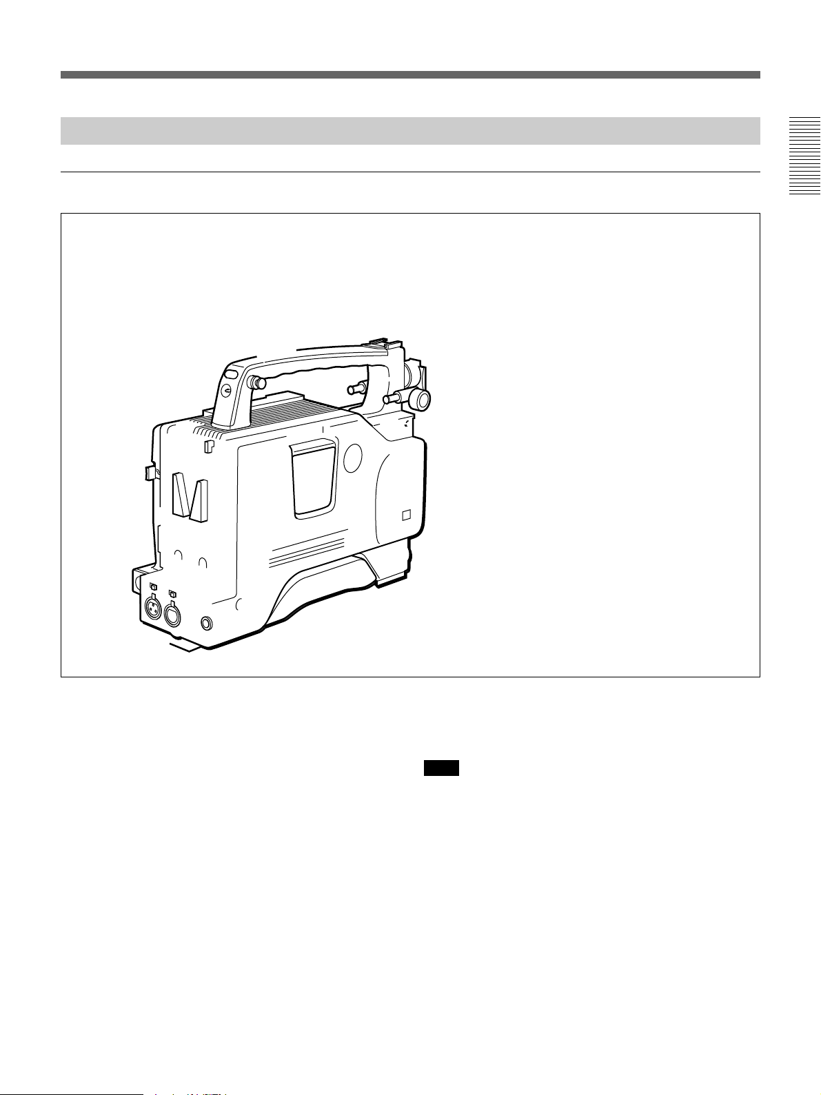
Overview
Product Configurations
Chapter1
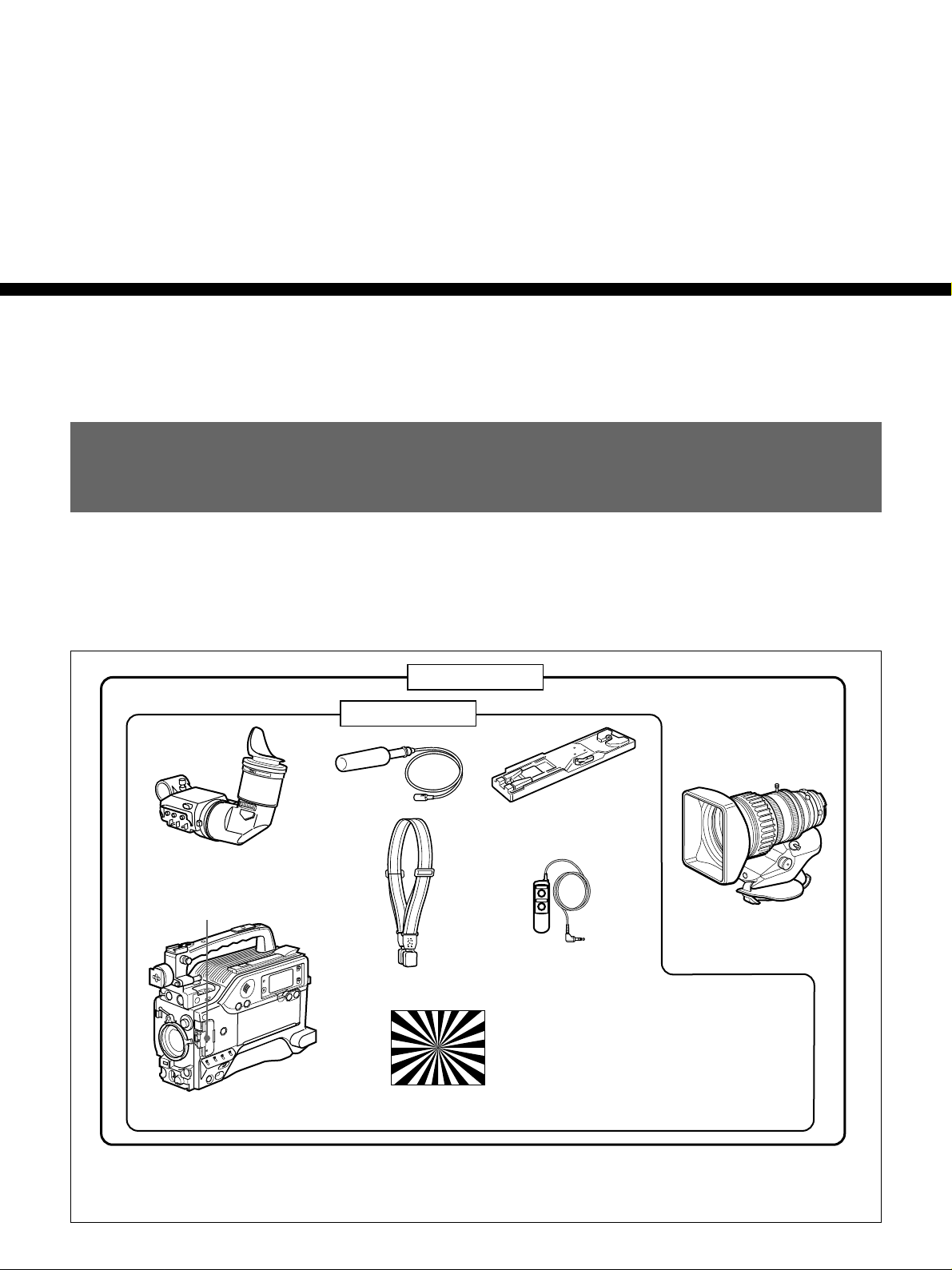
The four models, DSR-300AK, DSR-300AL, DSR300APK and DSR-300APL, comprise both NTSC and
PAL versions and the components as shown in the
figure below.
DSR-300AK/300APK
DSR-300AL/300APL
Microphone
DXF-801/801CE Viewfinder
Switch guard
b)
a)
Shoulder strap
The operation of the basic camcorder is the same in all
cases.
VCT-U14 Tripod
Adaptor
VCL-718BX
Zoom Lens
RM-LG1 Remote
Control Unit
DSR-300A/300AP Camcorder
a)Part No. A-8279-329-A (for DSR-300A)
Part No. A-8326-150-A (for DSR-300AP)
b)The switch guard can be removed. (see page 12)
Test chart for flange focal
length adjustment
• Lens mount cap
• Binding tie
• Operating instructions
Chapter 1 Overview 7

Features
Features on Camera Section
1
/2-inch IT type Power HAD CCD
Chapter 1 Overview
The DSR-300A/300AP Digital Camcorder uses 1/2inch IT type Power HAD CCDs. It excels in reduction
of smear, sensitivity and picture quality.
•Smear: –110 dB
•Sensitivity: F11.0 (at 3200 K, 2000 lux)
•S/N: 62 dB (DSR-300A) or 60 dB (DSR-300AP)
Sophisticated image processing
TruEye™ processing makes the following
performance features possible. This digital signal
processing has brought reproduction of natural colors
to the level achieved by the human eye.
DynaLatitude™
Enables detailed adjustment of contrast control in each
pixel in accordance with a histogram of luminance
signal levels (See page 52).
DCC+ (dynamic contrast control plus)
Prevents white breakup when shooting a high intensity
subject, and also prevents color faults in high intensity
subject.
New Functions boost operability
Controlling with the RM-VJ1 Remote Control
Unit
You can connect the optional RM-VJ1 Remote Control
Unit (equipped with microphone and monitor) to
control DSR-300A/300AP while watching the video
being shot. (See page 43.)
EZ (easy) mode function
When there isn’t time to check the camcorder settings,
simply press the EZ mode button to start the auto
adjustment function using standard settings. There is
no need to lose a shot for lack of setup time.
EZ (easy) focus
Press the EZ focus button before shooting to ensure a
quick and accurate focus.
1)
Dual pixel readout (DPR
When the gain is set to either 18 dB or 24 dB, the gain
setting can be doubled (6 dB up) without increasing
the noise level.
Programmable gain
The amount of gain relative to the GAIN switch setting
(H, M, or L) can be programmed as –3 dB, 0 dB, 3
dB, 6 dB, 9 dB, 12 dB, 18 dB, 18 dB+DPR, 24 dB,
24 dB+DPR and hyper gain.
)
Black stretch and compress
Enables control of luminance signal levels in black
areas without changing the hue.
Variety of detail corrections
•Skin detail function: this function gives a slightly
softer appearance to the subject’s face. The target
skin color can be automatically set.
•Black halo correction
•Red/green vertical detail correction: this function
performs vertical detail compensation for both red
and green signals.
•Horizontal detail frequency control
..........................................................................................................................................................................................................
1) DPR = Dual Pixel Readout
Hyper gain
Hyper gain (36 dB (=30 dB+DPR), or about 60 times
greater than 0 dB) can be easily set via one switch
setting. This can also be done from remote equipment.
Auto tracing white balance (ATW)
This function automatically traces the white balance,
which constantly changes as lighting conditions
change. Auto tracing white balance is especially
useful when there is no time to manually adjust the
white balance or when shooting moves between indoor
and outdoor locations.
Total level control system (TLCS)
Even if the incoming light exceeds the range in which
the standard auto iris can control exposure, the auto
gain control (AGC) or auto exposure (AE) backs up to
ensure proper exposure.
8 Chapter 1 Overview

Recording time (REC TIME) display
Recording time can be displayed in either of the
following modes.
1)
•Total recording time for all cuts (TTL
•Total recording time for current cut (DUR
)
2)
)
Viewfinder super detail
Video signals for the viewfinder are mixed with DTL
signals to make focusing easier.
Dual zebra pattern display
Two types of zebra patterns, zebra 1 and zebra 2 can
be displayed simultaneously or independently. The
zebra 1 can be set to the levels ranging from 70 to 90
IRE on the DSR-300A (or from 70 to 90% on the
DSR-300AP) and the zebra 2 indicates the levels of
100 IRE or more for the DSR-300A (or the levels of
100% or more for the DSR-300AP).
Color temperature display
When reading the white balance, the color temperature
is displayed on the viewfinder screen.
Switching the color temperatures for the
preset white balance
You can select the preset white balance at 3200 K or
5600 K by setting the FILTER control. The preset
white balance can be switched to other value when the
menu setting is changed (See page 84).
TM
SetupLog
function
Settings at shooting are recorded onto the tape in real
time. This recorded data can then be used to reproduce
the same shooting conditions in subsequent shots. It
also makes it easier to identify the cause of problems
in previous shots.
Video light control
A video light connector and control switch are
equipped. You can turn the light on and off
automatically as you start and stop the VCR operation.
High-performance viewfinder (DXF-801/
801CE)
•High resolution (600 TV lines of horizontal
resolution)
•DISPLAY switch that can turn the character display
on and off
•Light that can light the lens control elements
•Large-diameter eye cup for easier viewing and
focusing
•PEAKING potentiometer for vertical and horizontal
detail control
•Two indicators can be used as TALLY indicators
•Tough die-cast aluminum body
Chapter 1 Overview
Video monitor output with text
Features on VCR Section
The video signal with text superimposed that is shown
in the viewfinder can also be output to an external
video monitor.
The DSR-300A/300AP uses the DVCAM recording
format. The internal signal processing is digitalized to
provide more stable output signals and higher
1-kHz reference signal output
reliability.
Along with a color bar, a 1-kHz reference signal can
also be output.
Freeze mix function
The freeze mix function superimposes any previously
recorded still picture on the viewfinder screen to
facilitate framing the subject when reshooting the
Compatible with consumer DV
A DV cassette recorded on a DV-format VCR can be
played back on the DSR-300A/300AP. (Cassettes
recorded in LP mode cannot be played back.)
scene.
Edit Search Function
Pressing the EDIT SEARCH buttons allows the tape to
play back in search mode. Set either of two playback
speeds.
..........................................................................................................................................................................................................
1) TTL = Total 2) DUR = Duration
Chapter 1 Overview 9

Features
DVCAM cassettes
•The DSR-300A/300AP can use both standard-size
and mini-size DVCAM cassettes. According to
Chapter 1 Overview
cassette size, the DSR-300A/300AP automatically
corrects reel position.
•The maximum recording/playback times are 184
minutes for standard size cassettes and 40 minutes for
mini cassettes.
•DVCAM cassettes include a cassette memory.
Information about the editing points (ClipLink™ log
data) that is specified while shooting is recorded into
this cassette memory.
Recordable the external video signals
Fitting the optional DSBK-501/501P Analog
Composite Input Board enables the camcorder to
record external analog video signals. (See pages 24, 58
and 84.)
ClipLink™ function
PCM digital audio
Recording/playback can be set to audio lock mode.
You are able to select between two-channel recording
(with a sampling frequency of 48 kHz) mode or fourchannel recording (with a sampling frequency of 32
kHz) mode (CH-1 and CH-2 only).
Equipped with audio output connectors
During recording or playback, audio output can be
monitored via a built-in speaker, a connected earphone
or via (two-channel) audio output connectors.
Color playback
Connect an external video monitor for color playback
(playback adaptor not required). The DSR-300A/
300AP is equipped with two video monitor connectors:
one for composite video output and the other for Svideo output.
The ClipLink function links all stages from shooting to
editing. Once editing points have been set with this
function during shooting, they can be used to boost the
efficiency of editing work.
Creation of clips
Using the ClipLink function, the camcorder operator
can create clips to be used during editing.
The images captured at the Mark IN points are
recorded in a compressed format onto the tape as
“Index Pictures”
data (scene number, time code for Mark IN/OUT
points, etc.) is recorded in the cassette memory.
ClipLink mode
To use the ClipLink function, select the menu setting
to set the DSR-300A/300AP into ClipLink mode.
There is also a ClipLink continue function that enables
clips to be continued even after a break in recording.
1)
. In addition, editing point-related
VCR data display
The DSR-300A/300AP is able to display the following
data on the viewfinder screen.
•Time values (counter, time code, or user bit values)
•Audio recording levels
•Remaining tape time
•Operation mode of the VCR section
•Remaining battery capacity
•ClipLink information
Recording on external VCRs
Betacam or S-VHS VCRs can be connected to the
VTR connector (26-pin) on the rear panel.
..........................................................................................................................................................................................................
1) It is necessary to fit the optional DSBK-301A Index
Picture Board.
10 Chapter 1 Overview

Equipped with DV OUT connector
The DV OUT connector is i.LINK
1)
compatible. You
can connect Sony equipment with DV input
connectors.
You can do cut editing and digital dubbing if you
connect the DSR-70/70P Digital Videocassette
Recorder (with the DSBK-140 i.LINK/DV Input/
Output Board fitted) to the DV OUT connector on the
camcorder, using an i.LINK cable (DV connecting
cable). (See pages 26, 46, and 59.)
Chapter 1 Overview
..........................................................................................................................................................................................................
1) is a trademark of Sony Corporation and indicates that
this product is in agreement with IEEE 1394-1995
specifications and their revisions.
Chapter 1 Overview 11
Location and Function of Parts
Location and Function of Parts
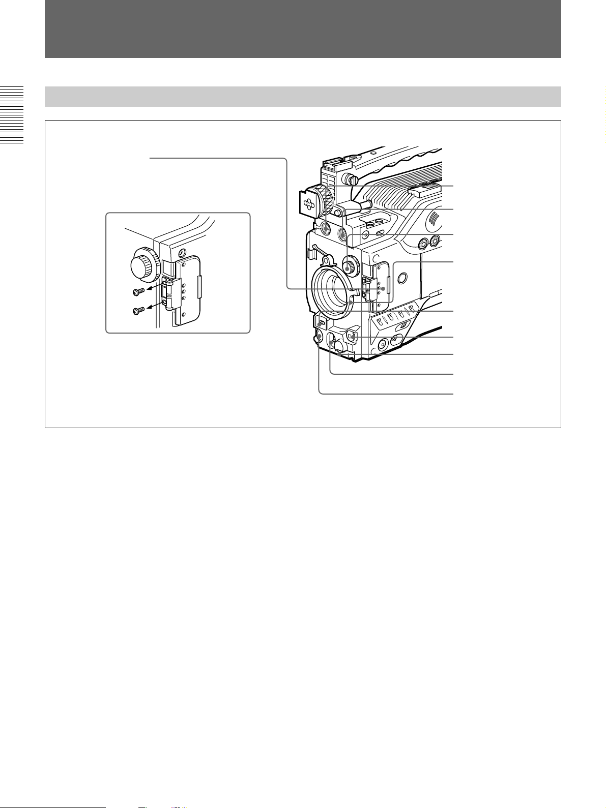
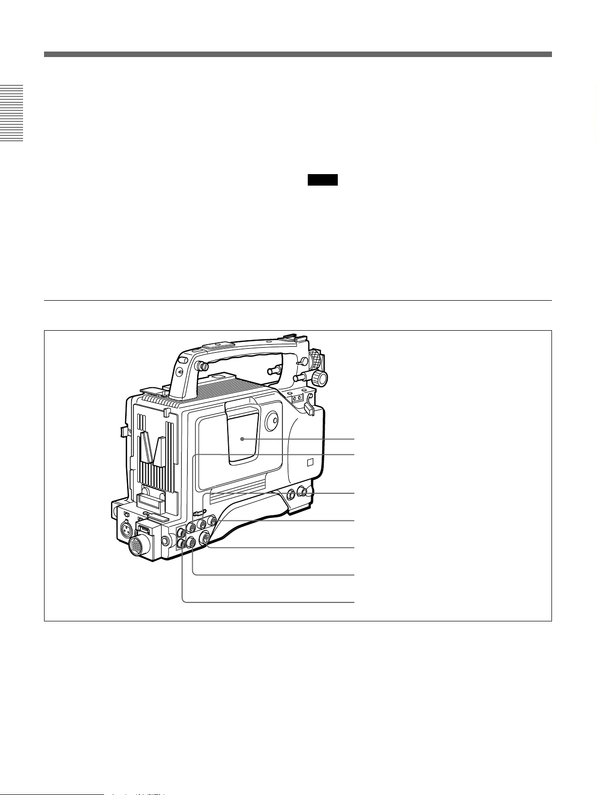
Front View
Chapter 1 Overview
0 Switch guard
How to remove the switch guard
1. Detach the two screws (M3).
2. Remove the switch guard, and replace
the screws detached in step 1.
1 MIC IN +48 V connector
2 VF connector
3 FILTER control
4 Lens mount
5 SHUTTER switch
6 TAKE button
7 AUDIO LEVEL knob
8 WHT/BLK switch
9 VTR button
1 MIC (microphone) IN +48 V connector (XLR 3-
pin, female)
Connect the supplied microphone or an optional
microphone (operable with a 48 V supply).
2 VF (viewfinder) connector (20-pin)
This is the connector for the DXF-801/801CE
viewfinder.
3 FILTER control
Select the color temperature conversion filter
appropriate to the lighting conditions. (See page 52.)
4 Lens mount
Attach the zoom lens here.
5 SHUTTER switch
Use this switch to set the shutter speed, CLS (clear
scan), or EVS setting (see page 110). Usually, set this
switch to OFF.
6 TAKE button
Press this button to specify an editing point (Mark IN/
OUT or Cue point) at the current tape position during
shooting. (See page 72.)
7 AUDIO LEVEL knob
You can use this knob to manually adjust the channel 1
audio recording level.
8 WHT/BLK (white/black) switch
This switch is used for automatic adjustment of the
white balance and black balance. (See pages 106 to
109.)
9 VTR button
Press this button to start and stop recording on the
VCR.
0 Switch guard
Prevents mis-operation of the EZ MODE button (4
on page 14), A.IRIS MODE switch (6 on page 14),
and ATW button (qf on page 14). When using these
buttons and switch, open the guard.
12 Chapter 1 Overview
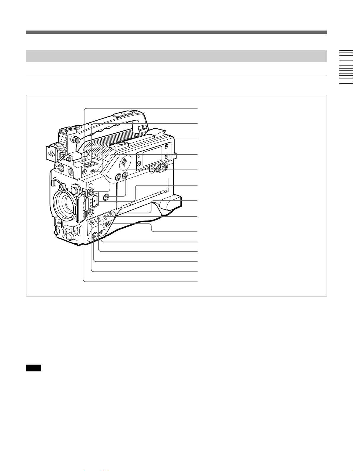
Right Side View
Front section
Chapter 1 Overview
1 EZ FOCUS button
2 EDIT SEARCH buttons
3 LIGHT switch
4 EZ MODE button and indicator
5 ZEBRA button and indicator
6 A.IRIS MODE switch and indicator
7 MENU switch
8 W.BAL switch
1 EZ FOCUS button
Press this button to turn the “easy focus” function on.
This opens the iris, to make it easier to focus before
shooting. The indication “EZ FOCUS” appears in the
viewfinder while the function is on; to turn it off, press
the EZ FOCUS button again. If left on, the function
automatically turns off after about ten seconds.
Note
If the “easy focus” function is still on when you press
the VTR button, it turns off automatically and
recording starts about one second later.
9 MENU dial
0 POWER switch
qa OUTPUT/DL/DCC+ switch
qs NG button
qd GAIN switch
qf ATW button and indicator
2 EDIT SEARCH buttons
You can see the search playback while pressing either
of these buttons at recording pause mode to quickly
find the next recording start point. Two playback
speeds are available. Press either of the buttons to the
inner position to increase the speed.
3 LIGHT (video light) switch
Controls the video light connected as follows.
AUTO: turns on the video light during recording if
the power switch on the light is set to on.
MAN (manual): allows the power switch on the
video light to turn the light on and off.
Chapter 1 Overview 13

Location and Function of Parts
4 EZ (“easy”) MODE button and indicator
Press this button (EZ mode on) when you want to
shoot immediately, with automatic adjustment of the
camcorder settings to standard values. (See page 93 for
EZ mode setting.) When this function is used, the iris
Chapter 1 Overview
and the white balance are adjusted automatically. (The
total level control system functions.) Press this button
again to return the camcorder to the previous settings
(EZ mode off).
Note
When the RM-M7G Remote Control Unit is
connected, the “EZ mode” function is disabled.
5 ZEBRA button and indicator
Depress this button to display a zebra pattern (diagonal
stripes) in the viewfinder.
Depending on the zebra setting in advanced menu page
4 (see page 91), the zebra 1 for video levels between
70 to 90 IRE (or 70 to 90%) and the zebra 2 for video
levels 100 IRE or more (or 100% or more) can be
displayed independently or simultaneously.
6 A.IRIS (auto iris) MODE switch and indicator
When you use the auto iris function (by setting the iris
selector on the lens to A), set this switch to suit the
shooting conditions. Selecting BACK L gives more
light to back-lit subjects, and selecting SPOT L adjusts
for high contrast in spot-lit subjects. For normal
shooting, set this switch to STD.
7 MENU switch
When you press this switch to the ON position, the
basic menu is displayed. Keep pressing it to the ON
position to cycle through the various menu displays.
When you press the switch to the STATUS position,
the camcorder’s status (of current settings) is
displayed.
8 W. BAL (white balance) switch
This selects the white balance setting from the preset
value, the value in memory A or the value in memory
B. (See page 107.) You can select the preset white
balance at 3200 K or 5600 K using the FILTER
control (3 on page 12). You can change the preset
color temperature on basic menu page 2. (See page
84.)
0 POWER switch
Powers the camcorder on or off.
qa OUTPUT/DL/DCC+ (DynaLatitude/dynamic
contrast control plus) switch
Use this switch to select the DCC+ function, the
DynaLatitude function, or color bar output.
Select the CAM/DCC+ position in most cases.
CAM/DCC+: This activates the DCC+ function.
This prevents color faults when shooting highintensity subjects.
CAM/DL: This setting uses the DynaLatitude
function, which finely adjusts the contrast of each
pixel according to a histogram of luminance signal
levels. Access advanced menu page 2 to set the
DynaLatitude function ON or OFF. The
DynaLatitude effect can be set to any of three
levels, Low, STD (standard), and High with basic
menu page 2.
BARS: This setting displays color bars.
For details of menu operation, see Chapter 4 “Viewfinder
Screen Displays and Menus” (See page 77).
qs NG button
When using the ClipLink function during shooting,
you can designate a particular scene as “NG” (No
Good) by pressing this button before shooting the next
scene. Press the button again to cancel the NG setting.
qd GAIN switch
This selects one of the three gain settings, high,
medium or low. You can choose the gain values
assigned to the H, M and L settings from values from
–3 dB to 24 dB + DPR and hyper gain. (See page 90.)
The factory default selections are 18 dB (H), 9 dB (M)
and 0 dB (L).
Note
When the HYPER GAIN switch (7 on page 22) is in
the ON position, the GAIN switch has no effect.
qf ATW (auto tracing white balance) button and
indicator
Press this button, turning the indicator on, when you to
automatically adjust the white balance to follow
changes in the lighting conditions. (See page 108.)
9 MENU dial
Use this dial to change menu pages or settings.
14 Chapter 1 Overview
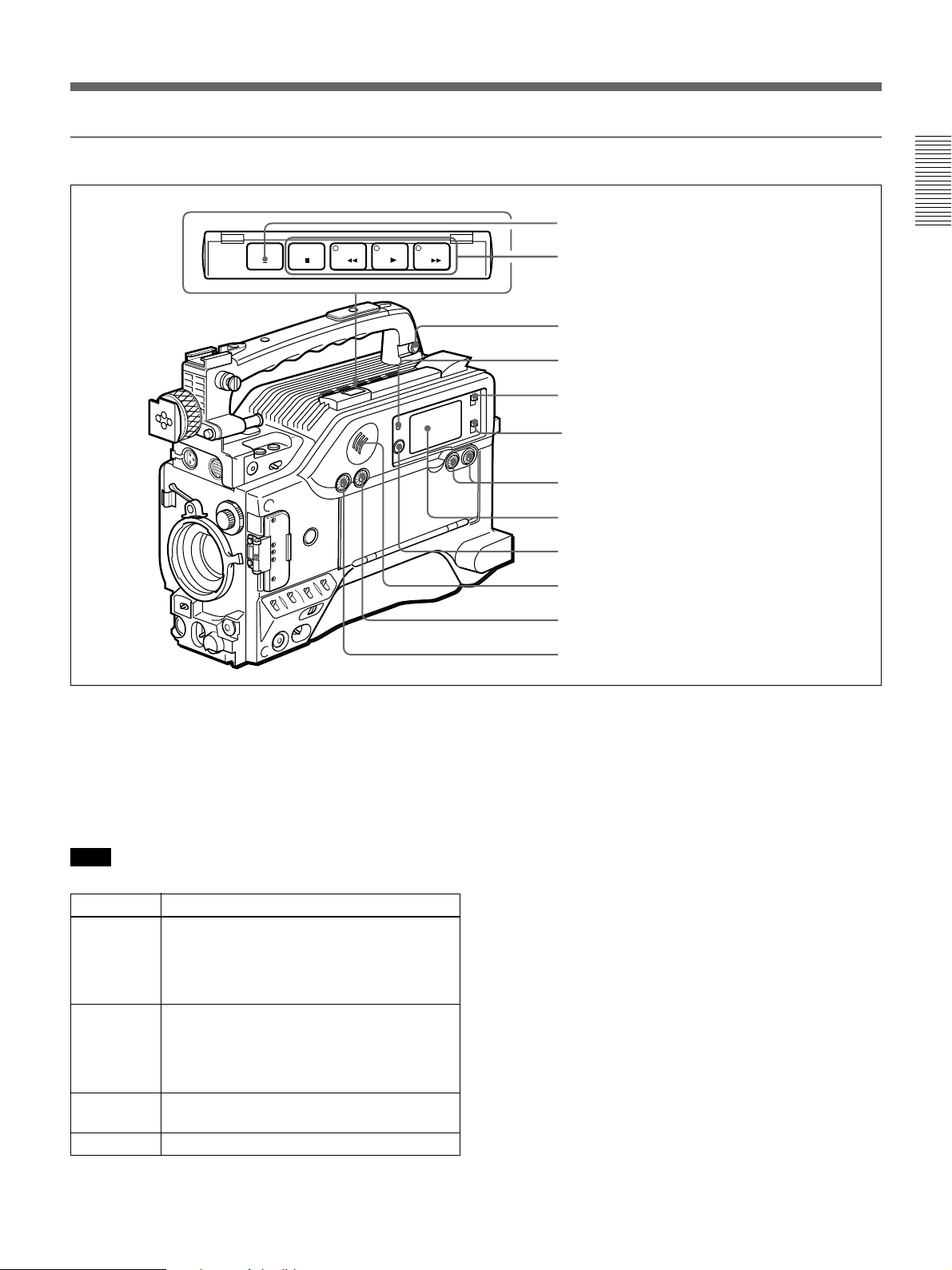
Rear section
EJECT
STOP
1 EJECT button
F FWD
PLAYREW
2 Tape transport buttons and indicators
3 EARPHONE connector
4 WARNING indicator
5 LIGHT switch
6 DISPLAY switch
7 AUDIO LEVEL (CH-1/CH-2) knobs
8 Display window
9 RESET/(MENU SET) button
0 Speaker
qa ALARM knob
qs MONITOR knob
Chapter 1 Overview
1 EJECT Z button
Press to open the cassette holder (1 on page 24) when
the camcorder is powered.
2 Tape transport buttons and indicators
These buttons transport the tape as shown below.
Note
During recording, none of these buttons operates.
Buttons
REW m
F FWD M Fast forwards the tape. The indicator lights
PLAY N Plays back the recorded video. The indicator
STOP x
Operation
Rewinds the tape. The indicator lights while
the tape is being rewound.
Press while the tape is being rewound or
during playback to view reverse search
playback.
while the tape is being fast forwarded.
Press while the tape is being fast forwarded
or during playback to view forward search
playback.
lights during playback.
Stops the tape.
3 EARPHONE connector (mini-jack)
Connect an earphone or headphones. This outputs the
same sound that would be output to the speaker (0 on
page 18), but mutes the speaker.
4 WARNING indicator
This lights or blinks when an abnormality occurs.
For details, see “Warning System” on page 122.
5 LIGHT switch
This switches the display window (8 on page 16)
light on or off.
6 DISPLAY switch
Switches time value indication shown in the display
window (8 on page 16).
COUNTER: Shows the tape transport time in
HH:MM:SS (hours, minutes and seconds).
TC: Shows the time code value.
U-BIT: Shows the user bit data in the time code.
Chapter 1 Overview 15
Location and Function of Parts
7 AUDIO LEVEL (CH-1/CH-2) (audio recording
level adjustments for channels 1 and 2) knobs
When the AUDIO SELECT (CH-1/CH-2) switches
(4 on page 20) are set to MAN, these knobs adjust
the audio levels being recorded on channels 1 and 2.
Chapter 1 Overview
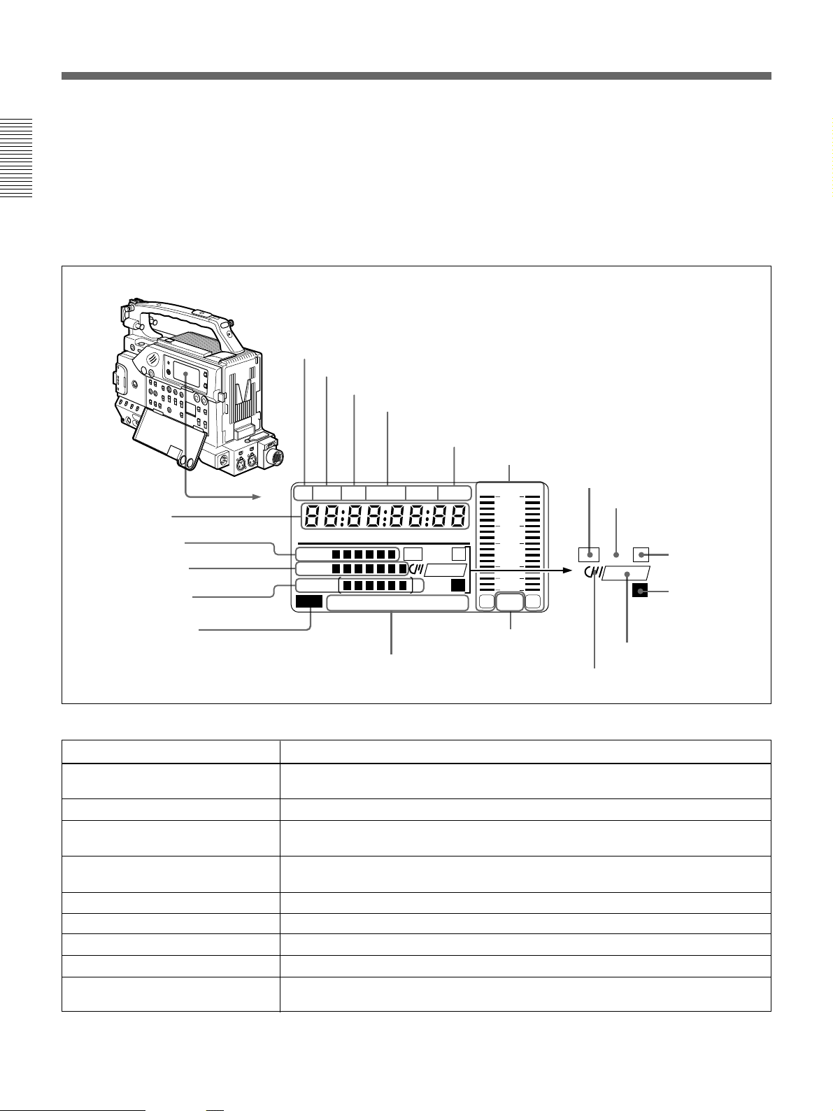
A Playback indication
PB DATE NDF EXT-LK HOLD
S Time value
indication
R Clip remaining
indication
Q Tape remaining
indication
P Battery capacity
indication
O Service indication
a) When the optional DSBK-301A is fitted
CLIP
TAPE
BATT
DIAG
The audio levels are indicated in the display window 8.
For details, see “8 Display window”.
8 Display window
Shows the following items. Use the LIGHT switch (5
on page 15) to light up the display window.
B DATE indication
C Non-drop frame indication (DSR-300A only)
D External synchronization lock indication
E Hold indication
F Audio level indicators
dB
OVER OVER
0
H MIN SEC FRM
CONT
DVCAM
IP
Li
CL
EF
RF SERVO HUMID SLACK
M Audio mode indications
N Warning indications
-12
-20
-30
-40
∞
-
F
8 32k
1
F
8 48k
G ClipLink log data indication
H ClipLink continue
indication
CL
CONT
I IP indication
IP
a)
DVCAM
J Lithium backup
2
L Cassette memory indication
Li
battery warning
K DVCAM indication
Indications in the display window
Indication
Description
A Playback indication Appears during playback, fast forward or rewind with the time data display showing a
time code or user bit value.
B DATE indication Appears when the date or time is displayed in the time value indication area S.
C Non drop-frame indication (DSR-
Appears when non-drop frame mode is selected.
300A only)
D External synchronization
indication
Appears when the internal time code generator is locked to an external signal input to
the TC IN connector (3 on page 24).
E Hold indication Appears when the internal time code generator is stopped.
F Audio level indicators These show the audio recording or playback levels of channel 1 and channel 2.
G ClipLink log data indication
H ClipLink continue indication
Appears when using a cassette with cassette memory containing ClipLink log data.
Appears when back space editing using ClipLink function is possible.
I IP (Index Picture) indication Appears when the ClipLink function is set to on in the VCR menu and Index Picture
recording is allowed. (The optional DSBK-301A is required.)
(Continued)
16 Chapter 1 Overview

Indications in the display window (continued)
Indication Description
J Lithium backup battery warning Appears when the voltage of the internal lithium backup battery (CR2032) is low. If this
indication appears, replace the lithium backup battery immediately.
For further information about replacing lithium battery, see “Inserting and Replacing
the Lithium Battery” (page 31).
K DVCAM indication Disappears when the cassette being played back is not for DVCAM format.
L Cassette memory indication Appears when using a cassette with cassette memory.
M Audio mode indications These show audio recording/playback mode.
Fs32k: 4-channel mode (32kHz sampling frequency)
Fs48k: 2-channel mode (48kHz sampling frequency)
For further information about selecting audio recording mode, see “Selecting Audio
Recording Mode Menu 212” (page 103).
N Warning indications Include the following.
RF: Appears when the video heads are clogged, or when there is a fault in the
recording system.
SERVO: Appears when the servo lock is not functioning.
HUMID: Appears when there is condensation on the drum.
SLACK: Appears when there is a tape winding fault.
Chapter 1 Overview
For measures against warning indications, see “Warning System” (page 122).
O Service indication Appears during maintenance on VCR menu operations (page 97). It does not appear
P Battery capacity indication
during normal operation.
This indicates the battery capacity and voltage as shown below.
Change menu setting for the battery you are using.
For menu settings, see “Selecting Battery Capacity Indication Menu 206” (page
100).
Battery voltage
Indication BP-L40/L40A/L60/L60A/ NP-1B/BP-90A
L90/L90A
BATT E[xxxxxx]F 15.0 V or more 12.5 V or more
BATT E[xxxxx ]F 14.0 to 15.0 V 12.0 to 12.5 V
BATT E[xxxxp]F 13.0 to 14.0 V 11.75 to 12.0 V
BATT E[xxx p]F 12.0 to 13.0 V 11.5 to 11.75 V
BATT E[xxpp]F 11.3 to 12.0 V 11.3 to 11.5 V
1)
BATT E[xxpp]F (blinking)
BATT E[x pp]F (blinking) 11.0 to 11.25 V 11.0 to 11.25 V
BATT E[ppp]F (blinking) 11.0 V or less 11.0 V or less
1)Replace the battery pack when this indication appears.
11.25 to 11.3 V 11.25 to 11.3 V
Chapter 1 Overview 17

Location and Function of Parts
Indications in the display window (continued)
Indication Description
Q Tape remaining indication During recording or pause mode, this indication shows the remaining tape time as
Chapter 1 Overview
R Clip remaining indication
shown below. It is not displayed when no cassette is loaded.
Indication Tape time remaining
TAPExxxxxxx 30 minutes or more
TAPExxxxxx 25 to 30 minutes
TAPExxxxx 20 to 25 minutes
TAPExxxx 15 to 20 minutes
TAPExxx 10 to 15 minutes
TAPExx 5 to 10 minutes
TAPEx 2 to 5 minutes
TAPEx (blinking) 0 to 2 minutes
TAPE (blinking) End of tape
1)
This shows how many clip shots or Cue points can be recorded
Indication Clip shots Cue point
CLIPxxxxxx 51 or more 101 points or more
CLIPxxxxx 41 to 50 81 to 100 points
CLIPxxxx 31 to 40 61 to 80 points
CLIPxxx 21 to 30 41 to 60 points
CLIPxx 11 to 20 21 to 40 points
CLIPx 1 to 10 1 to 20 points
CLIPx (blinking)
CLIP Cannot record
CLIP (blinking)
2)
2)
1 to 3 1 to 6 points
Cannot record
.
1) The optional DSBK-301A is required for Index Picture recording.
2) When back space editing using ClipLink function is possible (when CONT is displayed)
S Time value indication Depending on the DISPLAY switch (6 on page 15) setting, this shows a counter
9 RESET/(MENU SET) (counter reset/VCR
value, time code value or user bit value. Press the MENU button (1 on page 19) to
display the VCR menu.
Also, this button is used to change menu settings.
menu) button
Resets the time value shown in the display window.
This button operates differently depending on settings
For details on the VCR menu, see “Setting on the VCR
Section VCR Menu” (page 97).
of the DISPLAY switch (6 on page 15) and the TC
mode switch 1 (9 on page 20) and 2 (8 on page 20).
0 Speaker
Outputs the recorded or playback audio. When a
Switch setting RESET button operation
DISPLAY: COUNTER Resets counter value to
0:00:00.
DISPLAY: TC
TC mode switch 1: PRESET
TC mode switch 2: SET
DISPLAY: U-BIT
TC mode switch 1: PRESET
TC mode switch 2: SET
Resets time code to
00:00:00:00.
Resets user bit
00 00 00 00.
a)
to
warning indicator appears in the viewfinder or display
window, the speaker sounds a warning tone.
The speaker is muted (does not output a warning tone)
when an earphone is connected to the EARPHONE
connector (3 on page 15).
For details on the warning tone, see “Warning System”
(page 122).
a) Bits of time code recorded on tape, in which users can
record necessary information.
18 Chapter 1 Overview
qa ALARM (alarm tone volume adjustment) knob
Controls the volume of the warning tone that is output
via the speaker (0 on page 18) or earphone (3 on
page 15). Turning this knob to the minimum setting
mutes the alarm tone.
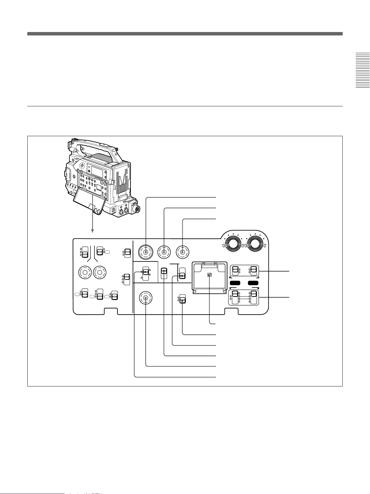
Operation panel under the cover
Right side
qs MONITOR (monitor volume adjustment) knob
Controls the volume of the sound other than the
warning tone that is output via the speaker (0 on page
18) or earphone (3 on page 15). Turning this knob to
the minimum setting mutes the audio output.
1 MENU button
2 ADVANCE button
3 SHIFT button
Chapter 1 Overview
MENU
ClipLink
ADVANCE SHIFT
PRESET
CH-1
REGEN
CH-2
DATE/TIME
REC TIME SKIN DTL EXT VTR
TTL
DUR
OFF
TTL RESET
ON
OFF
HYPER
GAIN
H.SAT
STD
SET
MATRIX
FL
ON
COMPONENT.
OFF
PARALLEL
INT ONLY
EXT ONLY
FRONT MIC
LOW CUT
ON
OFF
OUTPUT
VBS
Y/C
VTR
TRIGGER
MONITOR SELECT
MIX
EXT
CONTINUE
1 MENU button
Press this button to display the VCR menu in the
display window.
For details about the VCR menu, see “Setting on the VCR
Section —VCR Menu” (page 97).
2 ADVANCE button
When setting time code and user bit values, or at menu
AUDIO LEVEL
F-RUN
F-RUN
R-RUN
MONITOR OUT
CHARACTER
ON
OFF
SET
LITHIUM BATT
VJ MIC
WIRELESS
AUTO
MAN
AUDIO SELECT
CH-1
AUDIO IN
FRONT
REAR
CH-2
4 AUDIO SELECT
(CH-1/CH-2)
switches
5 AUDIO IN (CH-1/
CH-2) switches
6 Lithium battery compartment
7 MONITOR OUT CHARACTER switch
8 TC mode switch 2
9 TC mode switch 1
0 ClipLink CONTINUE button
qa MONITOR SELECT switch
setting, press this button to increment the digit that has
been selected with the SHIFT button (3 on page 20).
In other case, keep pressing this button to show the
clip remaining indication instead of time value.
(Example: CLIP 045)
For time code and user bit settings, see page 64.
On how to use the ADVANCE button for menu settings, see
“Setting on the VCR Section —VCR Menu” (page 97).
Chapter 1 Overview 19

Location and Function of Parts
3 SHIFT button
When setting time code and user bit values, or at menu
setting, keep pressing this button to select a digit. The
selected digit will start blinking.
In other case, keep pressing this button to show the
Chapter 1 Overview
date (when the DISPLAY switch (6 on page 15) is
set to U-BIT) and time (when the DISPLAY switch is
set to TC) instead of time value.
For time code and user bit settings, see page 64.
On how to use the SHIFT button for menu settings, see
“Setting on the VCR Section —VCR Menu” (page 97).
4 AUDIO SELECT (CH-1/CH-2) (audio recording
level adjustments manual/auto selection for
channels 1 and 2) switches
These select the audio recording level adjustment
method.
AUTO: Use the AGC (automatic gain control) circuit
to automatically adjust the audio level.
MAN: Enables users to manually adjust the AUDIO
LEVEL (CH-1/CH-2) knobs (7 on page 16) for
each channel. Select AUTO if excess input levels
are likely to occur.
5 AUDIO IN (CH-1/CH-2) (audio input selection
for channels 1 and 2) switches
These select the input signals to channels 1 and 2.
FRONT: Signals from the microphone connected to
the MIC IN +48 V connector.
VJ MIC: Signals from the remote control unit with
microphone connected to the REMOTE connector
2
WIRELESS: Signals from the WRR-855A
synthesized tuner connected to the WRR
connector via the CA-WR855 Camera Adaptor.
REAR: Signals from a microphone or external
equipment connected to the AUDIO IN (CH-1/
CH-2) connectors.
6 Lithium battery compartment
Insert the supplied CR2032 Lithium Battery.
On how to fit the lithium battery, see page 31.
Note
Set this switch ON when using the freeze mix
function.
8 TC (time code) mode switch 2
Sets the mode for advancing time code values when
the TC mode switch 1 9 has been set to PRESET.
F-RUN: The time code advances continuously
whether or not the camcorder is recording. Use
this setting to align the time code value with real
time.
SET: Use this setting to set the time code or user bit
value.
R-RUN: The time code value advances only during
recording. Use this setting to have consecutive
recordings on the tape.
Note for the DSR-300A
There are two time code frame modes: drop-frame
(DF) mode and non drop-frame (NDF) mode. This
product is shipped with drop-frame mode selected.
For details on switching between drop-frame mode and non
drop-frame mode, see “Selecting Frame Mode (DF/NDF)
for Time Code (for DSR-300A only) —Menu 204” (page
99).
For details on drop-frame mode and non drop-frame mode,
see “Drop-frame mode (for DSR-300A only)” on page 67.
9 TC (time code) mode switch 1
Selects between resetting the time code value or
continuing from the time code value at the end of the
previous recording.
PRESET: This starts recording time code values on
the tape from the currently set value.
REGEN: During back space editing, this reads the
tape’s current time code value and sets the time
code to record starting from that value. The time
code value is advanced in R-RUN mode
regardless of the setting on TC mode switch 2 8.
DATE/TIME: This synchronizes the time code to
the real time clock set in the VCR menu (see page
99). In this case the time code of the DSR-300A is
recorded in DF (drop-frame mode).
7 MONITOR OUT (monitor output)
CHARACTER switch
Set ON to superimpose text information on the
monitor output.
20 Chapter 1 Overview
Note
If the ClipLink function is set to on (meaning ClipLink
shooting is allowed) in menu 211 and CONT is
displayed in the display window, regardless of the
setting of this switch, the time code generator
automatically enters the REGEN mode at recording.
(When not performing ClipLink shooting, set the
ClipLink function to oFF (see page 70)).
0 ClipLink CONTINUE button
When restarting ClipLink shooting, press this button to
add the new clip at the end of the recorded clips.
Note
When restart recording without pressing this button,
the pre-recorded ClipLink log data and Index Pictures
are deleted.
For details , see “ClipLink Shooting” (page 70).
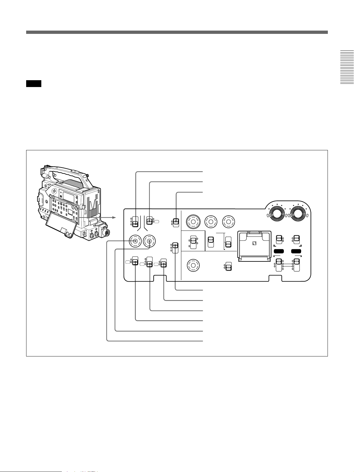
Left side
REC TIME SKIN DTL EXT VTR
TTL
DUR
OFF
TTL RESET
HYPER
GAIN
ON
OFF
H.SAT
STD
FL
SET
MATRIX
ON
COMPONENT.
OFF
PARALLEL
INT ONLY
EXT ONLY
FRONT MIC
LOW CUT
ON
OFF
TRIGGER
qa MONITOR SELECT (audio monitor selection)
switch
Selects audio output via the speaker (0 on page 18) or
earphone.
CH-1: Channel 1 audio
MIX: Mixed audio (channels 1 and 2)
CH-2: Channel 2 audio
EXT: The sound selected by an external VCR
connected to the VTR connector (0 on page 26)
1 REC TIME switch
2 SKIN DTL switch
3 EXT VTR OUTPUT switch
MENU
ClipLink
ADVANCE SHIFT
PRESET
CH-1
REGEN
CH-2
DATE/TIME
F-RUN
F-RUN
R-RUN
MONITOR OUT
CHARACTER
ON
OFF
SET
LITHIUM BATT
VJ MIC
WIRELESS
AUDIO LEVEL
AUTO
MAN
AUDIO SELECT
CH-1
AUDIO IN
FRONT
REAR
OUTPUT
VBS
Y/C
VTR
MONITOR SELECT
MIX
EXT
CONTINUE
Chapter 1 Overview
CH-2
1 REC (recording) TIME switch
Selects the recording time indication in the viewfinder.
TTL (TOTAL): Displays the total recording time.
The total recording time is not reset even when
you stop the VCR and power off the camcorder,
for example, to replace the battery pack.
DUR (DURATION): Displays the recording time of
the current cut.
4 VTR TRIGGER switch
5 FRONT MIC LOW CUT switch
6 MATRIX switch
7 HYPER GAIN switch
8 SKIN DTL SET button
9 TTL RESET button
OFF: Switches off the recording time display.
If, however, in advanced menu 6 you set the time
code display item (TC IND) to ON (see page 92),
then the VCR time data (time code, counter, or
user bit value) is displayed.
Chapter 1 Overview 21

Location and Function of Parts
Note
The recording time displayed when this switch is set to
TTL or DUR is obtained by counting the duration of
the internal reference signal input to the camcorder.
The value may not agree exactly with the value
Chapter 1 Overview
derived from the time code values. Furthermore, the
value displayed may not be correct when another
manufacture’s VCR is connected to the camcorder.
2 SKIN DTL (skin detail) switch
Set this switch to ON to use the skin detail correction
function.
For details, see “Skin Detail Correction” (page 117).
3 EXT VTR OUTPUT switch
Depending on the external VCR connected to the VTR
connector (0 on page 26), this switches the video
signal output to the VCR.
COMPONENT, VBS: Component/composite video
signal
Y/C: S-video signal
4 VTR TRIGGER switch
Sets the function of the VTR button on the camcorder
or lens when a VCR is connected to the VTR
connector (0 on page 26).
PARALLEL: Operates both internal and external
VCRs.
INT ONLY: Operates the internal VCR only.
External VCR operation is performed locally.
EXT ONLY: Operates the external VCR only.
7 HYPER GAIN switch
Setting this switch to ON increases the gain by a factor
of about 60 with respect to 0 dB (a 30 dB increase by
electronic amplification and a 6 dB increase for DPR,
bringing about a total gain increase of 36 dB).
When this switch is in the ON position, the indication
“HYPER” appears in the viewfinder, and the GAIN
UP indicator in the viewfinder also lights.
When finished shooting, return this switch to OFF
position. The “HYPER” indication disappears and the
GAIN UP indicator goes out.
Note
Increasing the gain with this switch reduces the
horizontal resolution by approx. 50%.
8 SKIN DTL (skin detail ) SET button
Press this button with the SKIN DTL switch 2 to
display the area detect cursor on viewfinder screen.
Place the cursor on the target and press this button to
perform skin detail correction.
For details, see “Skin Detail Correction” (page 117).
9 TTL (total) RESET button
Pressing this button resets the total recording time
(TTL selection) to 0.
5 FRONT MIC LOW CUT switch
Set this switch to ON to insert a high-pass filter in the
microphone circuit, reducing wind noise.
Normally leave the switch in the OFF position.
6 MATRIX switch
Selects the color matrix setting to change the picture
color adjustment.
H.SAT: Colors are emphasized.
FL: Colors appear normal even when shooting under
fluorescent lighting.
STD: The color matrix in standard setting is used.
Normally leave the switch in this position.
22 Chapter 1 Overview
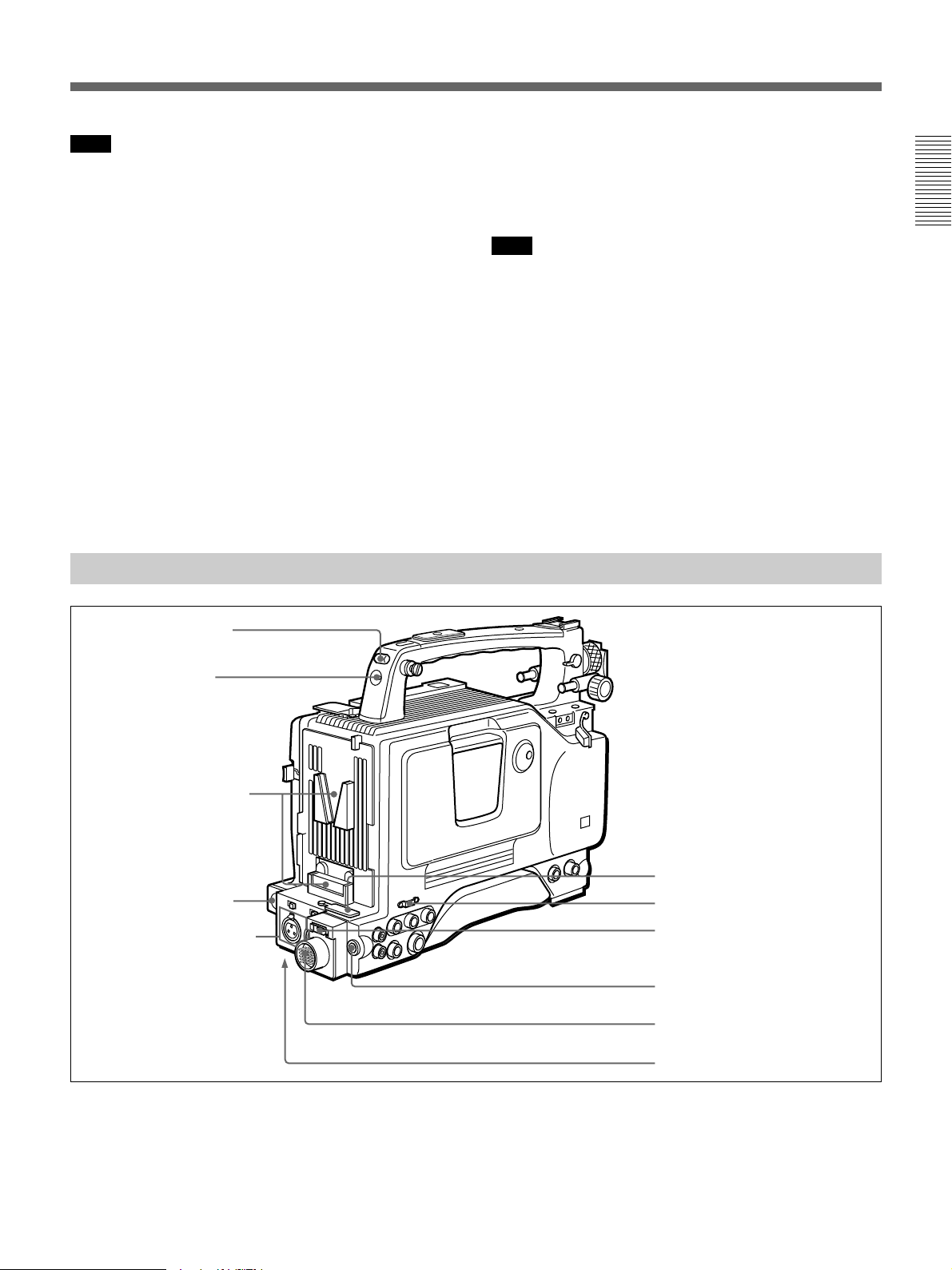
Left and Upper View
Front section
Chapter 1 Overview
1 Shoulder strap fitting
1 Shoulder strap fitting
To use the supplied shoulder strap, fix one end here
and the other end to the right side. (See page 39.)
2 Attachment shoe for large viewfinder
This allows you to attach the optional electronic
viewfinder. (See page 36.)
3 Accessory fitting shoe and screw hole
Attach optional video lights or other accessories.
4 Viewfinder left-to-right positioning ring
Loosen this ring to adjust the left-to-right position of
the viewfinder. (See page 35.)
5 Viewfinder fitting shoe
Fix the DXF-801/801CE Viewfinder.
6 REMOTE connector 1 (mini-jack)
Connect the RM-LG1 Remote Control Unit to enable
remote operation of the ClipLink function.
Note
The RM-81 cannot be connected.
If you connect the optional cable (Sony part number:
1-790-779-11) to this connector, you can control the
zoom using the optional RM-VJ1 Remote Control Unit
(equipped with microphone and monitor), even when
using the conventional lens.
For details, consult your Sony dealer.
7 Viewfinder front-to-back position locking knob
Loosen this knob to adjust the front-to-back position of
the viewfinder. (See page 35.)
Chapter 1 Overview 23
Location and Function of Parts
8 Fitting for optional microphone holder
You can fit an optional CAC-12 Microphone Holder
here. (See page 37.)
9 Video light connector
Chapter 1 Overview
A video light with a maximum power consumption of
30 W such as the Anton Bauer Ultralight 2 or
equivalent can be connected.
0 LENS connector (12-pin)
If you use a lens with cable, connect the lens cable.
qa VIDEO OUT connector (BNC)
This outputs the video signal captured by the
camcorder.
Rear section
qs REMOTE connector 2 (10-pin)
Connect the optional RM-M7G Remote Control Unit
to this connector. Set the CAMERA SELECT switch
on the bottom of RM-M7G to 1.
You can also connect the RM-VJ1 Remote Control
Unit (equipped with microphone and monitor.)
Notes
•EZ mode cannot be used if the RM-M7G is
connected to the camcorder.
•Be sure to turn off the power of the camcorder before
connecting the RM-M7G/VJ1.
•Be sure to turn off the power of the camcorder before
disconnecting the equipment connected to this
connector. Otherwise, the camcorder will not work
properly.
a) When the optional DSBK-501/501P is fitted
1 Cassette holder
Power the camcorder and press the EJECT button to
open the lid. Insert the cassette and close the lid by
pressing the indication “PUSH” .
2 GEN LOCK IN (gen lock video input)/VIDEO
IN (video input) connector (BNC)
GEN LOCK IN: When synchronizing the camcorder
to an external signal, input a reference videos
ignal (VBS or BS). (See page 84.)
24 Chapter 1 Overview
1 Cassette holder
2 GEN LOCK IN/VIDEO IN connector
3 TC IN connector
4 TC OUT connector
5 S VIDEO OUT connector
6 MONITOR OUT connector
7 AUDIO OUT CH-1/CH-2 connectors
a)
VIDEO IN: When the optional DSBK-501/501P
Analog Composite Input Board is fitted to the
camcorder, you can input the analog video signals
(VBS) to this connector.
3 TC IN (time code input) connector (BNC)
Input an external signal for synchronizing the built-in
time code generator. Use an SMPTE (DSR-300A) or
EBU (DSR-300AP) time code signal.
Note
Use a jitterless LTC signal. Using an LTC signal
reproduced by other equipment may cause the
camcorder to malfunction.
4 TC OUT (time code output) connector (BNC)
This outputs time code signals from the built-in time
code generator. When a time code signal is input to
the TC IN connector (3 on page 24), this output
signal is synchronized to it.
6 MONITOR OUT (output) connector
Outputs the image being shot or played back as
composite video signals. Connect to the video input
connector on an external VCR or video monitor.
Note
The output signal from this connector may discontinue
when switching the operation between recording and
playback. Do not use as a reference signal for external
equipment.
Chapter 1 Overview
For details about time code, see “Setting Time Values” on
page 64.
5 S VIDEO OUT (S-video output) connector (DIN
4-pin)
This outputs the image being shot or played back as Svideo signals. Connect to the S-video input connector
on an external VCR or video monitor.
Rear and Bottom
1 TALLY indicator
2 TALLY switch
3 Battery attachment
interface
7 AUDIO OUT CH-1/CH-2 (audio output channel
1 and 2) connectors (phono jacks)
These output the sound being recorded or played back.
Connect to a stereo amplifier or video monitor’s audio
input connectors.
4 DC IN connector
5 AUDIO IN CH-1/CH-2
connectors and input
selection switches
1 TALLY (back tally) indicator (red)
This indicator lights during recording. It will not light
if the TALLY switch 2 is set to OFF. This indicator
also blinks to indicate warnings in the same manner as
the REC/TALLY indicator in the viewfinder.
6 WRR connector
7 Cable clamp
8 DV OUT connector
9 DC OUT connector
0 VTR connector
qa BREAKER button
2 TALLY switch
Set this switch to ON to activate the TALLY indicator
1 function.
For details, see “Warning System” on page 122.
Chapter 1 Overview 25
Location and Function of Parts
3 Battery attachment interface
Attach a battery pack or an AC-DN1 AC Adaptor.
When using the WRR-855A synthesized tuner (for
wireless microphones), attach the CA-WR855 Camera
Adaptor here.
Chapter 1 Overview
For information about fitting a battery pack or an AC
adaptor, see “Power Supply” (page 47). For information
about attaching a synthesized tuner, see “Connecting to
Audio System” (page 40).
4 DC IN (DC power input) connector (XLR 4-pin,
male)
To use the camcorder with an AC power supply
connect an optional AC-550/550CE or CMA-8A/
8ACE AC Adaptor.
i.LINK cable (DV
connectin cable)
Binding tie
8 DV OUT connector (6-pin)
Connect to the DV input connector of an external VCR
via an i.LINK cable.
5 AUDIO IN CH-1/CH-2 (audio input channel 1
and 2) connectors (XLR 3-pin, female) and input
selection switches
Connect a microphone or other external audio
equipment. Set the input selection switches as
shown below according to the microphone or
equipment.
MIC+48V ON (right position): For connecting to a
48-V microphone
Note
If this position is selected for a microphone other than
48-V microphone, the microphone may be damaged.
MIC (center position): For connecting any
microphone other than 48-V microphone
LINE (left position): For connecting an external
audio signal source such as a stereo amplifier.
6 WRR (synthesized tuner) connector (7-pin)
Insert the WRR-855A synthesized tuner into the CAWR855 Camera Adaptor and connect the CA-WR855
here.
For information about attaching a synthesized tuner, see
“Connecting to Audio System” (page 40)
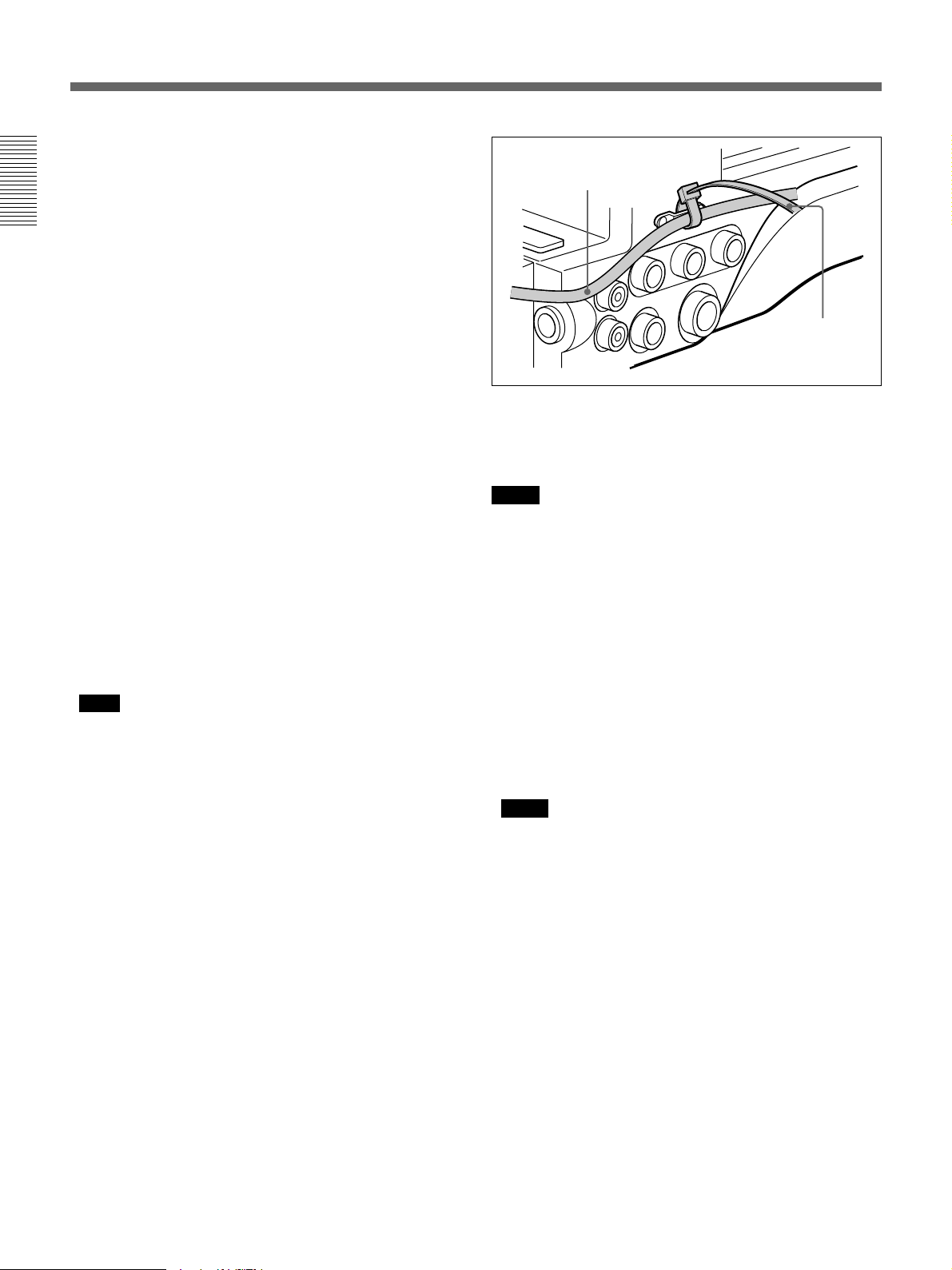
7 Cable clamp
Fasten an i.LINK cable (DV connecting cable) to the
clamp using the supplied binding tie so that the plug is
not pulled out from the DV OUT connector 8.
Notes
• This connector will not work as an input connector.
• When external equipment, such as a VCR, is
connected to this connector, the ClipLink function
and the function for audio fade-in/fade-out during
recording do not work.
9 DC OUT (DC power output) connector (4-pin,
female)
This connector supplies power for a WRR-810A/860A
UHF Portable Tuner.
0 VTR connector (26-pin, male)
Connect an external VCR.
Notes
• This connector always outputs the signals from the
camera. It is impossible to output the playback
video of the internal VCR.
• A camera control unit (CCU) cannot be connected
to this connector.
• The image size on the viewfinder or on the screen of
the RM-VJ1 does not switch automatically, even if
the aspect ratio (16:9/4:3) of the return signal, input
from an external VCR, is switched.
qa BREAKER (breaker reset) button
If an excessive current flows in the internal circuits,
the internal circuit breaker shuts off the power supply.
Push this button after eliminating the cause of the
excessive current.
26 Chapter 1 Overview

VCL-718BX Zoom Lens
When using a lens other than VCL-718X, see page 34 and
page 114 (“Designating the lens”).
Chapter 1 Overview
1 Iris ring
2 Zoom ring
3 Focus ring
Lens hood
9 RET button
0 VTR button
4 M button
5 F.B adjustment ring
and F.B fixing knob
6 MACRO ring
7 ZOOM selector
8 Zoom remote control
connector
qa Instant automatic iris adjustment button
qs IRIS selector
qd Motorized zoom lever
1 Iris ring
For manual iris control, set the IRIS selector qs to the
“M” position, and turn this ring.
2 Zoom ring
For direct manual zoom control, set the ZOOM
selector 7 to the “MANU.” position, and turn this
ring.
3 Focus ring
Turn this ring to focus the lens on the subject.
4 M (close-up) button
For close-up work, turn the MACRO ring 6 while
holding this button down. (See page 115.)
5 F.B (flange focal length) adjustment ring and
F.B (flange focal length) fixing knob
F.B adjustment ring : To adjust the flange focal
length, loosen the F.B fixing knob, then turn the
ring. (See page 113.)
F.B fixing knob: Fixes the F.B adjustment ring.
6 MACRO (close-up) ring
For close-up, turn this ring while holding the M button
down. (See page 115.)
7 ZOOM selector
This selects the mode of zoom operation.
SERVO: power zoom
MANU. (manual): manual zoom
Chapter 1 Overview 27

Location and Function of Parts
8 Zoom remote control connector (8-pin)
Connect the optional LO-26 Lens Remote Control Unit
for remote control of zooming.
9 RET (return) button
Chapter 1 Overview
This allows you to check the video signal.
When the internal VCR is in recording pause mode,
press this button to review the last few seconds of the
recording in the viewfinder (recording review). When
an external VCR is connected, pressing this button
connects the E-E video signal
to the viewfinder while the internal VCR is recording
or no tape is inserted in the internal VCR.
For details, see “Playback — Checking Recorded Contents”
(page 63).
0 VTR button
This button starts and stops recording on the VCR.
Press it once to start recording, and once more to stop.
1)
from the external VCR
qa Instant automatic iris adjustment button
While using manual iris control, press this button to
switch temporarily to automatic iris control setting.
Automatic control is maintained as long as you hold
the button down.
qs IRIS selector
This selects the mode of iris operation. (See page
114.)
A (automatic): automatic iris
M (manual): manual iris
qd Motorized zoom lever
Use this to carry out a power zoom. Pressing the lever
harder increases the zoom speed.
W end: zoom toward wide angle
T end: zoom toward telephoto
..........................................................................................................................................................................................................
1) E-E video signal: “electric-to-electric” video signal.
This is an input video signal which has passed through
internal electrical circuits, but which has not been
converted to a magnetic signal.
28 Chapter 1 Overview
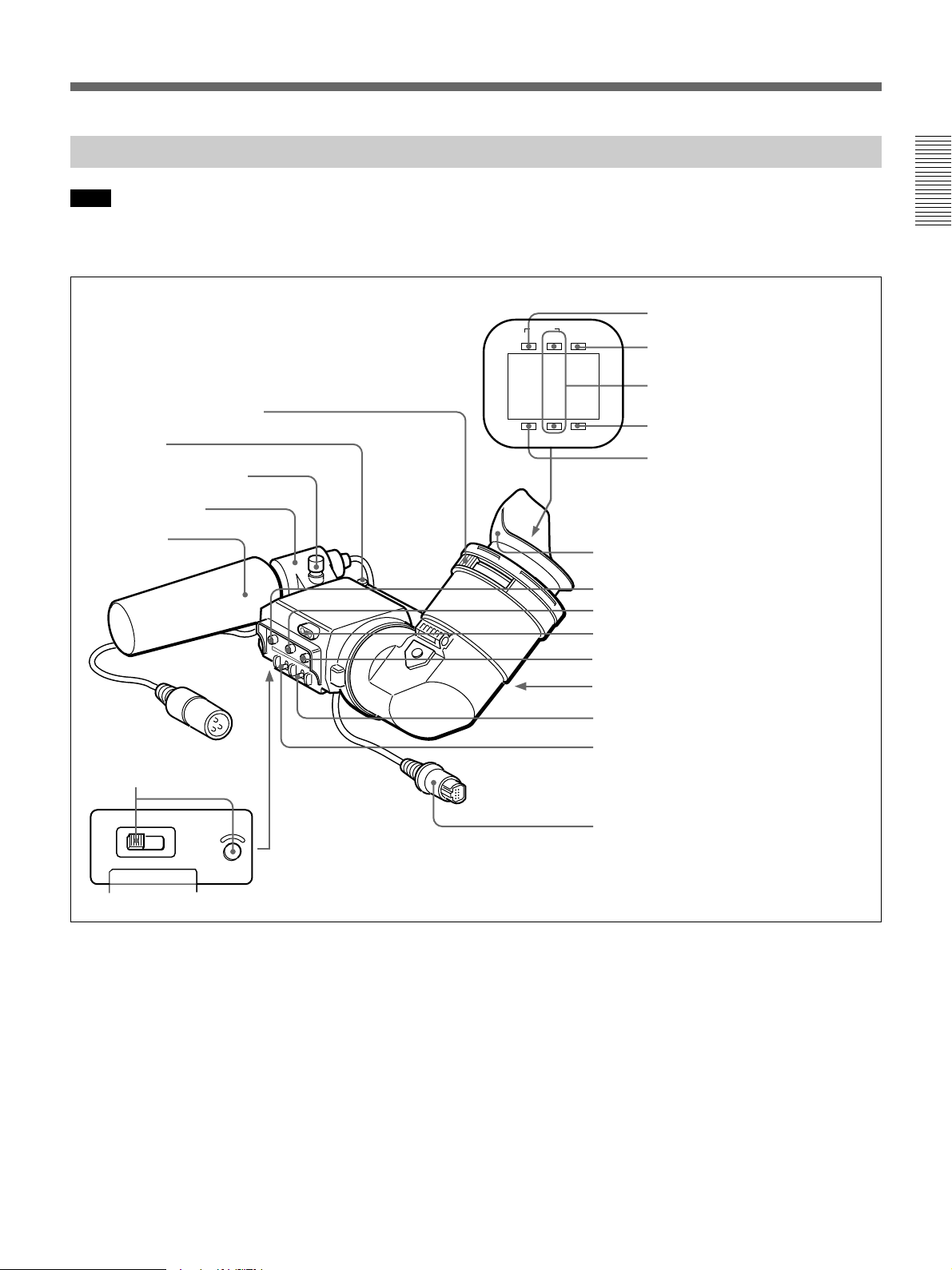
DXF-801/801CE Viewfinder
Note
You can switch the scan size of the DXF-801/801CE
in accordance with the aspect ratio selected on the
1 Eyepiece focusing knob
2 Stopper
Microphone holding screw
Microphone holder
Microphone
camera or camcorder. However, it operates in 4:3
mode when used on the DSR-300A/300AP.
TALLY
TAKE BATTREC
SHUTTER GAIN UP
Eye cup
9 PEAKING control
0 CONTRAST control
qa Tally lamp
qs BRIGHT control
4 TAKE/TALLY indicator
5 BATT indicator
6 REC/TALLY indicators
7 GAIN UP indicator
8 SHUTTER indicator
Chapter 1 Overview
3 LIGHT switch and light
HIGH LOW OFF
LIGHT
1 Eyepiece focusing knob
Turn this to adjust the viewfinder focus to match your
eyesight. (See page 112.)
2 Stopper
Lift up when detaching the viewfinder (See page 35).
3 LIGHT switch and light
The light lights the lens and the switch controls the
light as follows.
HIGH/LOW: Turn the light on and control the
brightness.
OFF: Turns the light off.
qd Eyepiece release catch
qf TALLY switch
qg DISPLAY switch
qh Viewfinder connector
4 TAKE/TALLY indicator (orange)
When using the ClipLink function while shooting, this
indicator lights when the TAKE button (6 on page
12) has been pressed to set a Mark IN point and goes
out when a Mark OUT point is set.
5 BATT (battery) indicator (red)
This lights when the battery capacity is low.
Chapter 1 Overview 29

Location and Function of Parts
6 REC/TALLY (recording/tally) indicators (red)
•This flashes from the time when you press the VTR
button (9 on page 12 and 0 on page 28) on the lens
or camcorder until recording starts, then stays on
Chapter 1 Overview
continuously during recording.
•This is also used to indicate a fault. (See page 122.)
•The lower indicator can be disabled by menu setting.
(See page 91.)
7 GAIN UP indicator (orange)
This lights when the gain is 3 dB or more.
8 SHUTTER indicator (red)
This lights when the SHUTTER switch (5 on page
12) is in the ON position. (If the EVS is selected, the
indicator will not light.)
9 PEAKING control
This adjusts the outline intensity of the viewfinder
image. (See page 112.)
0 CONTRAST control
This adjusts the contrast of the viewfinder image. (See
page 112.)
qa Tally lamp
When the TALLY switch qf is in the ON position, this
operates in the same way as the REC/TALLY
indicators 6.
qs BRIGHT (brightness) control
This adjusts the brightness of the viewfinder image.
(See page 112.)
qd Eyepiece release catch
To view the viewfinder screen directly, press this
catch, and hinge up the eyepiece.
qf TALLY switch
Set this switch to the ON position to use the tally lamp
qa.
qg DISPLAY switch
Set this switch to OFF when you want to remove the
character data from the viewfinder and the monitor
connected to the MONITOR OUT connector.
However, items which are set to OFF in advanced
menu page 5 and page 6 are not displayed even when
this switch is set to ON.
qh Viewfinder connector (20-pin)
Connect this to the VF connector (
30 Chapter 1 Overview
2
on page 12).
 Loading...