

Sony DVCAM DSR-250, DSR-250P Service Manual

General
Peak inrush current (DSR-250P)
(1) Hot switching inrush current,
measured in accordance with
European standard EN55103-1:
6.3 A (230 V)
Power requirements
14.4 V (Lithium-ion battery pack)
12 to 17 V (AC power adaptor)
Average power consumption
(when using the battery pack)
During camera recording using
LCD
12.1 W
Viewfinder
10.5 W
Input/Output connectors
VIDEO IN/OUT
Input/output auto switch
RCA pin-jack, 1 Vp-p, 75 ohms,
unbalanced, sync negative
S VIDEO
Input/output auto switch
4-pin mini DIN
Luminance signal: 1 Vp-p,
75 ohms, unbalanced
Chrominance signal: 0.286 Vp-p
75 ohms, unbalanced
AUDIO IN/OUT CH-1/CH-2
Input/output auto switch
RCA pin-jack, 245 mV, (at output
impedance more than 47 kilohms)
Output impedance with less than
2.2 kilohms
Input impedance more than
47 kilohms
AUDIO IN CH1/CH2
XLR 3-pin, female
–60 dBu: 6.8 kilohms,
+4 dBu: 6.8 kilohms
(0 dBu = 0.775 Vrms)
PHONES
Stereo minijack (ø 3.5 mm)
LANC control jack
Stereo mini-minijack (ø 2.5 mm)
MIC IN +48V
XLR 3-pin, female
VF
20-pin
LIGHT
2-pin
DV IN/OUT
6-pin connector
Speaker
Dynamic speaker (ø 20 mm)
DC IN 12V
XLR 4-pin, female
DC OUT 12V
4-pin, male
LCD screen
Picture
2.5 type measured diagonally
49.9 × 37.3 mm (2 × 1 1/2 in)
Total dot number
200 640 (880 × 228)
Video camera
recorder
System
Video recording system
2 rotary heads
Helical scanning system
Audio recording system
Rotary heads, PCM system
Quantization: Fs32 kHz (12 bits,
channels 1/2, channels 3/4),
Fs48 kHz (16 bits, channels 1/2)
Video signal
PAL colour, CCIR standards
NTSC color, EIA standards (DSR-250),
Usable cassette
DVCAM cassette with the
mark printed
Mini DVCAM cassette with the
mark printed
DV cassette with the
mark
printed
Mini DV cassette with the
mark printed
Tape speed
DVCAM format:
Approx. 28.218 mm/s
DV format SP mode: Approx.
18.812 mm/s
Recording/playback time
DVCAM format: 184 min (using
cassette PDV-184ME)
DV format SP mode: 270 min
(using cassette PDV-184ME)
Fast-forward/rewind time
Approx. 45 s (using cassette
DVM60/PDVM-40ME)
Approx. 2 min 30 s (using cassette
PDV-184ME)
Viewfinder
Electric viewfinder (B&W)
Image device
1/3 type CCD (3 Charge Coupled
Device) Approx. 380 000 pixels
(DSR-250), Approx. 450 000 pixels
(DSR-250P)
(Ef
(Effective: Approx. 340 000 pixels)
fective: Approx. 400 000 pixels)
Lens
Combined power zoom lens
Filter diameter 58 mm (2 3/8 in)
12× (Optical), 48× (Digital)
F1.6 - 2.4
Focal length
6 - 72 mm (1/4 - 2 7/8 in)
When converted to a 35 mm still
camera
43.2 - 518.4 mm (1 3/4 - 20 1/2 in)
Colour temperature
Auto, nIndoor (3 200 K),
Outdoor (5 800 K), (A, B)
Minimum illumination
2 lux (F1.6)
(DSR-250P)
(DSR-250), 0.3 Vp-p (DSR-250P),
Operating temperature
0 °C to 40 °C (32 °F to 104 °F)
Storage temperature
–20 °C to +60 °C (–4 °F to +140 °F)
Dimensions (approx.)
242 × 251 × 509 mm (9 5/8 × 10 ×
20 1/8 in) (w/h/d)
Mass (approx.)
3.5 kg (7 lb 11 oz)
main unit only
4.9 kg (10 lb 13 oz)
including the BP-L40 (A) battery
pack, cassette PDV-184ME,
microphone, viewfinder, and
hood cap
Supplied accessories
See page 2.
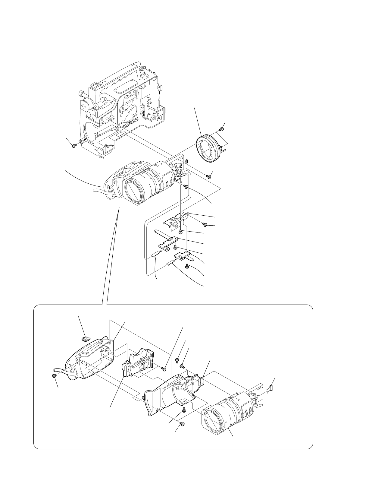
SERVICE MANUALSERVICE MANUAL
R MECHANISM
— Continued on next page —
Photo : DSR-250
RMT-811
US Model
Canadian Model
DSR-250
AEP Model
DSR-250P
DIGITAL CAMCORDER
SPECIFICATIONS
NTSC model : DSR-250
PAL model : DSR-250P
DSR-250/250P
RMT-811
Ver 1.0 2000. 08

2-2
NOTE: Follo w the disassembly procedure in the numerical order given.
2-1. LCD SECTION (PD-126 BOARD, INVERTER TRANSFORMER UNIT)
PD-126
Board
0
LCD unit
LCD unit
qd
PD-126 board,
Inverter
transformer unit
7
Screw
(M1.7 × 2.5),
lock ace, p2
9
P cabinet (M)
assembly
8
Two screws
(M1.7 × 2.5),
lock ace, p2
5
Two screws
(M1.7
×
2.5),
lock ace, p2
qs
Two claws
3
P cabinet (C)
1
LCD unit
(24P)
3
Back light
Cold cathode
fluorescent tube
2
Remove the
three solderings
6
Remove the
six solderings
7
Inverter
transformer unit
8
PD-126 board
5
PCB clip
4
PCB clip
REMOVING THE PD-126 BOARD,
INVERTER TRANSFORMER UNIT
2
Two screws (M2 × 4),
lock ace, p2
1
Two screws (M2 × 4),
lock ace, p2
4
T wo screws
(M2 × 4),
lock ace, p2
A
A
B
B
P
D
-1
2
6
B
o
a
rd
P
D
-12
6
B
o
a
rd
qa
Back light
6
BL retainer
qf
Shoulder pad assembly
Cold cathode fluorescent tube,
BL shield sheet (N)
PD-126 board
LANC
jack
Adjustment remote
commander (RM-95)
[PD-126 BOARD SERVICE POSITION]
Regulated power supply
AC I
N
12V
Inverter transformer unit
Back light
Cold cathode fluorescent tube,
BL shield sheet (N)
How to make the DC cable
(See page 2-1)

2-3
2-2. CARRYING HANDLE SECTION (TH-010, ME-019 BOARDS, VF SHOE BASE)
8
qs
ME-019
ME-019
3
VF slide shoe 3
2
Shoe washer
1
Four screws
(M3 × 25)
4
Lock ring (D),
Lock ring rubber
8
VF shoe base
7
Slide arm
REMOVING VF SHOE BASE
Carrying handle
block assembly
7
Two claws
6
T wo screws
(M3 × 8)
5
T wo screws
(M3 × 8)
9
Carrying handle
block assembly
2
Rear handle
cover assembly
qd
ME-019
board
0
T wo screws
(M2.6 × 5), spring bolt
qa
T wo screws
(M2 × 4), lock ace, p2
REMOVING THE ME-019 BOARD
1
Two screws (M2 × 4),
lock ace, p2
4
TH-010
board
3
Screw
(M2 × 3),
lock ace, p2
6
Two small washers W4
5
Two hexagon sockets
(M4
×
12) bolt
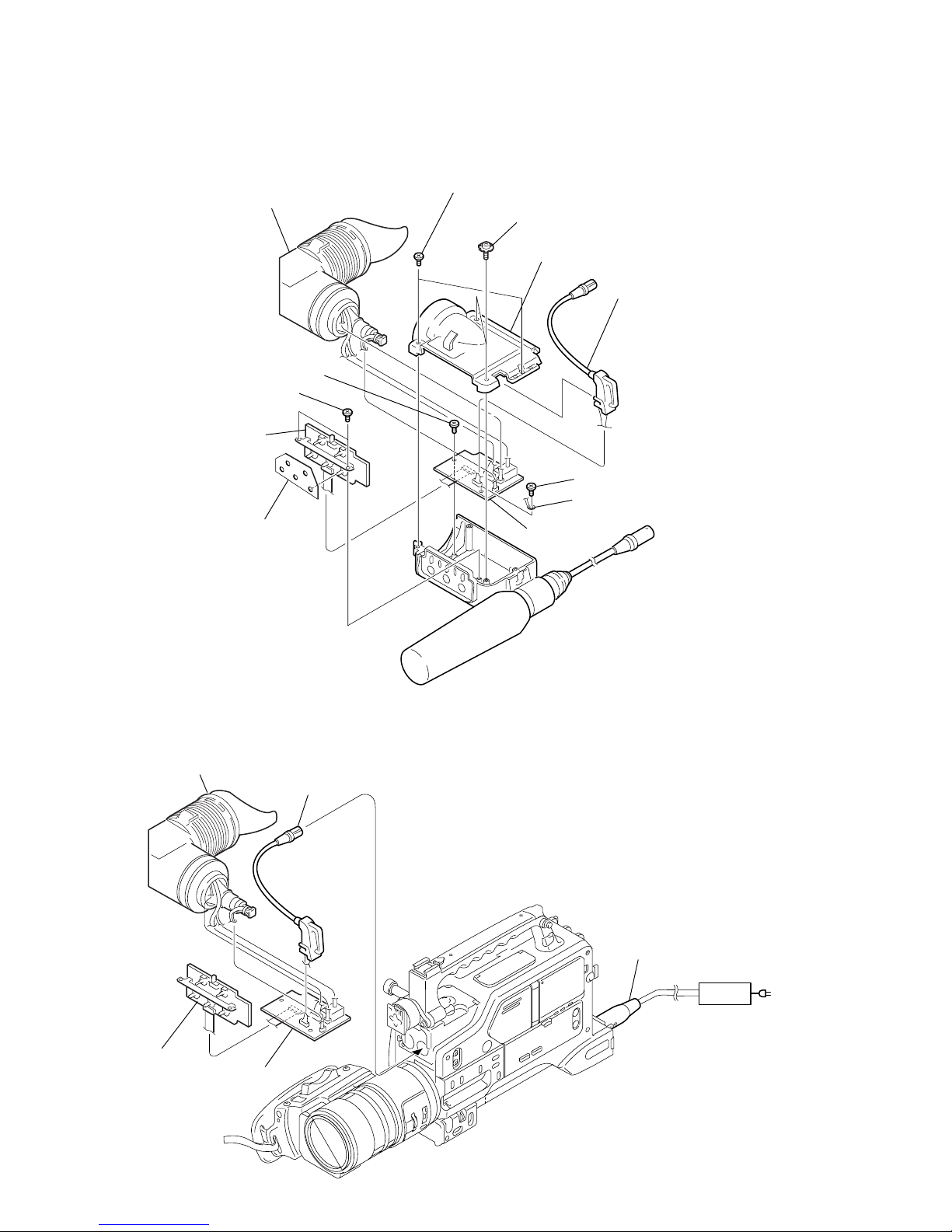
2-4
2-3. VF SECTION (MAIN, SUB BOARDS)
3
Bottom case
7
Lug terminal
4
VF cable
9
MAIN board
0
Two screws
(M2.6 × 4)
qs
SUB board
SUB board
qa
Parting plate
VF cable
MAIN board
VF assembly
DXF-801 (DSR-250),
DXF-801CE (DSR-250P)
5
VF assembly
DXF-801 (DSR-250),
DXF-801CE (DSR-250P)
1
T wo screws
(M3 × 6)
8
Screw
(M2.6 × 4)
6
Screw (M2.6 × 4)
2
T wo screws
(M3 × 8)
[VF SECTION MAIN, SUB BOARDS SERVICE POSITION]
Regulated power supply
AC I
N
12V
How to make the DC cable
(See page 2-1)
Refer to the separate DXF-801/810CE Service Manual (attach to the end of this manual) [ Section 1. Service Information ].

2-5
2-4. CABINET (R) BLOCK ASSEMBLY (SW-343 BOARD)
1
Seven screws (M2 × 3),
lock ace, p2
2
Screw (M2 × 3),
lock ace, p2
4
VR knob
6
SP cabinet
assembly
3
SW protection sheet
5
VR knob
4
Cabinet (R) block assembly
Cabinet (R) block assembly
7
SW-343 board
SP901
SB-036 board
KP-011 board
AE-023 board
PM-040 board
VI-156
Board
VI-156
Board
SW
-343
SB-036
3
FP-245 flexible board (10P)
1
Two screws (M3 × 8)
2
Two screws
(M3 × 8)
REMOVING THE SW-343 BOARD
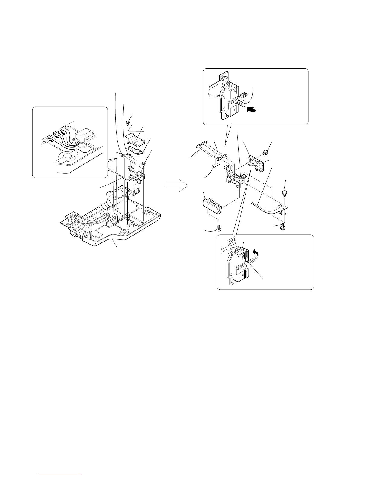
2-6
4
Three screws (M2 × 3),
lock ace, p2
8
Screw
(M1.7 × 2.5)
lock ace, p2
9
Screw
(M1.7
×
2.5)
lock ace, p2
0
FP-241 flexible
board (6P)
1
FP-241 flexible
board (6P)
5
Hinge lid
2
Screws
(M1.7 × 2.5)
lock ace, p2
6
Hinge cover (rear)
1
Two screws
(M1.7 × 2.5)
lock ace, p2
7
Hinge cover
(front)
qs
Harness
fixed tape
qg
Hinge assembly
7
Three screws
(M2 × 4),
lock ace, p2
3
Harness
(PS-111) (14P)
qf
Harness
(PS-111) (14P)
3
Two claws
4
Claws
6
Blind plate
assembly
qd
Harness
(PS-110)
(8P)
5
Remove the hinge cover (rear)
in the direction of the arrow.
2
Harness
(PS-110) (8P)
Cabinet (R) block assembly
SW-343
SB-036
REMOVING HARNESS (PS-111) (14P),
HARNESS (PS-110) (8P)
qa
Remove the harness
(PS-111) (14P),harness
(PS-110) (8P) in the
direction of the arrow.
When removing it, be careful not
to damage the harnesses, etc.
1
2
3
2-5. HINGE SECTION (HINGE ASSEMBLY, FP-241 FLEXIBLE BOARD)
2-7
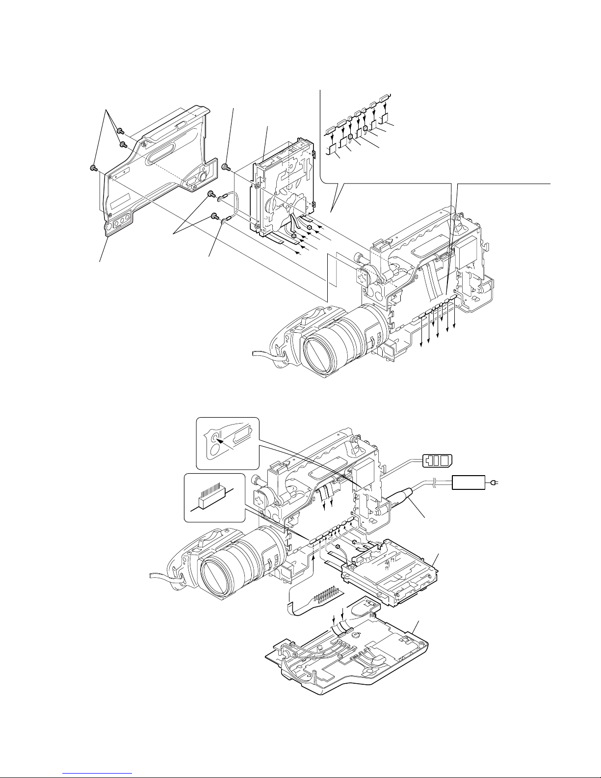
2-6. CABINET (L) ASSEMBLY, MECHANISM DECK
VI-156
Board
VI-156
Board
6
7
8
0
9
qa
qs
VI-156
Board
0
8
9
6
qa
7
qs
A
A
B
B
3
Four screws
(M3) step
qd
Mechanism
deck
2
Cabinet (L) assembly
5
Harness
(JJ-059)
Mechanism deck
qs
qa
0
9
8
7
6
SW-343
SB-036
CN007 20P
20
1
4
Two screws (M2 × 3),
lock ace, p2
LANC
jack
How to make the DC cable
(See page 2-1)
1
Five screws
(M3 × 8)
6
Flexible board (from capstan motor) (18P)
7
Flexible board (from drum motor) (11P)
8
Harness (from loading motor) (2P)
9
Flexible board (from drum motor) (10P)
0
Harness (from cam motor) (2P)
qa
FRV-008 flexible flat cable
(from MD-76 board) (21P)
qs
FRV-008 flexible flat cable
(from MD-76 board) (21P)
[MECHANISM DECK SERVICE POSITION]
Cabinet (R) block assembly
Regulated power supply
AC IN
12V
CPC-13 jig
(J-6082-443-A)
Adjustment remote
commander (RM-95)
2-8
2-7. DD-146, IN-057 BOARDS
VI-156
Board
A
A
D
C
B
C
D
B
2
DD-146 board
4
IN-057 board
VI-156
Board
A
A
D
C
B
C
D
B
DD-146 board
IN-057 board
D
D
-1
4
6
D
D
-1
4
6
S
W
-3
4
3
S
B
-0
3
6
1
Two screws (M2 × 3),
lock ace, p2
3
Two screws (M2 × 3),
lock ace, p2
Cabinet (R) block assembly
How to make the DC cable
(See page 2-1)
Regulated power supply
AC IN
12V
[DD-146, IN-057 BOARDS SERVICE POSITION]

2-9
2-8. VI-156 BOARD
Connection to Check the VTR Section
To check the VTR Section, set the VTR to the "forced VTR power ON" mode.
Operate the VTR functions using the adjustment remote commander (with the HOLD switch set in the OFF position)
(However, connect the cabinet (L) assembly when cassette is going to be ejected only.)
Setting the “Forced VTR Power ON” mode
1) Select page: 0, address: 01, and set data: 01.
2) Select page: D , address: 10, set data: 02, and press
the PAUSE button of the adjustment remote
commander.
Exiting the “Forced VTR Power ON” mode
1) Select page: 0, address: 01, and set data: 01.
2) Select page: D , address: 10, set data: 00, and press
the PAUSE button of the adjustment remote
commander.
3) Select page: 0, address: 01, and set data: 00.
A
B
G
G
H
H
D
C
E
F
B
D
C
E
F
A
qf
VI-156 board
VI-156
Board
qa
Control switch block (EG-1044) (6P)
qd
FP-243 flexible board (27P)
qs
FP-242 flexible board (39P)
0
CD-274 board (50P)
9
Harness (VF-071) (3P)
8
Harness (VG-052) (12P)
7
Harness (VM-068) (12P)
6
Harness (MV-124) (7P)
5
Harness (VL-054) (6P)
V
I-156
B
oard
VI-156 board
VIDEO OUT
VIDEO IN/OUT
TV monitor
Connect the CPC-13 jig (J-6082-443-A)
during tape path check.
CN007 20P
20
1
CN013 (8P)
1
8
[SERVICE POSITION TO CHECK THE VTR SECTION]
3
Harness (VH-050) (12P)
4
FVK-001 flexible flat cable (8P)
2
Two screws (M2 × 3),
lock ace, p2
1
Six screws (M2 × 3),
lock ace, p2
LANC jack
How to make the DC cable
(See page 2-1)
Regulated power supply
AC IN
Adjustment remote
commander (RM-95)
JK-197 board
12V
When you want to eject
a cassette, short-circuit
pin-7 of CN-013 with its
pin-8 (GND) with a jumper
for one second.
2-10
2-9. LENS BLOCK ASSEMBLY
(ON-001, NO-001 BOARDS, CONTROL SWITCH BLOCK (CF-1044))
A
A
qd
Three screws
(M2
×
6) lock ace, p2
qa
Three screws (M2 × 3),
lock ace, p2
8
Screw (M2 × 3),
lock ace, p2
7
ON-001 board,
FP-243 flexible board (27P)
0
NO-001 board,
FP-242 Flexible board (39P)
qs
On bracket
qg
Lens block assembly
3
T wo screws
(M3
×
8)
2
Screw (M3 × 8)
1
Screw
(M3 × 8)
4
Screw (M3 × 8)
5
Screw (M2 × 3),
lock ace, p2
qf
Mi ring assembly, Control switch block
(EG-1044) (6P)
6
Flexible board (27P)
9
Flexible board
(39P)
0
Grip assembly
8
Slide knob assembly
9
Control switch block (CF-1044),
Harness (VG-052) (12P)
5
Screw (M3 × 8)
6
Grip base
4
T wo screws
(M3
×
8)
qa
Lens block assembly
2
Screw (M3 × 6)
EG grip
1
Three screws (M3 × 6) EG grip
3
Screw (M3 × 8)
7
Two screws (M2 × 4),
lock ace, p2
Harness (VG-052)
(12P)
REMOVING CONTROL SWITCH BLOCK (CF-1044)
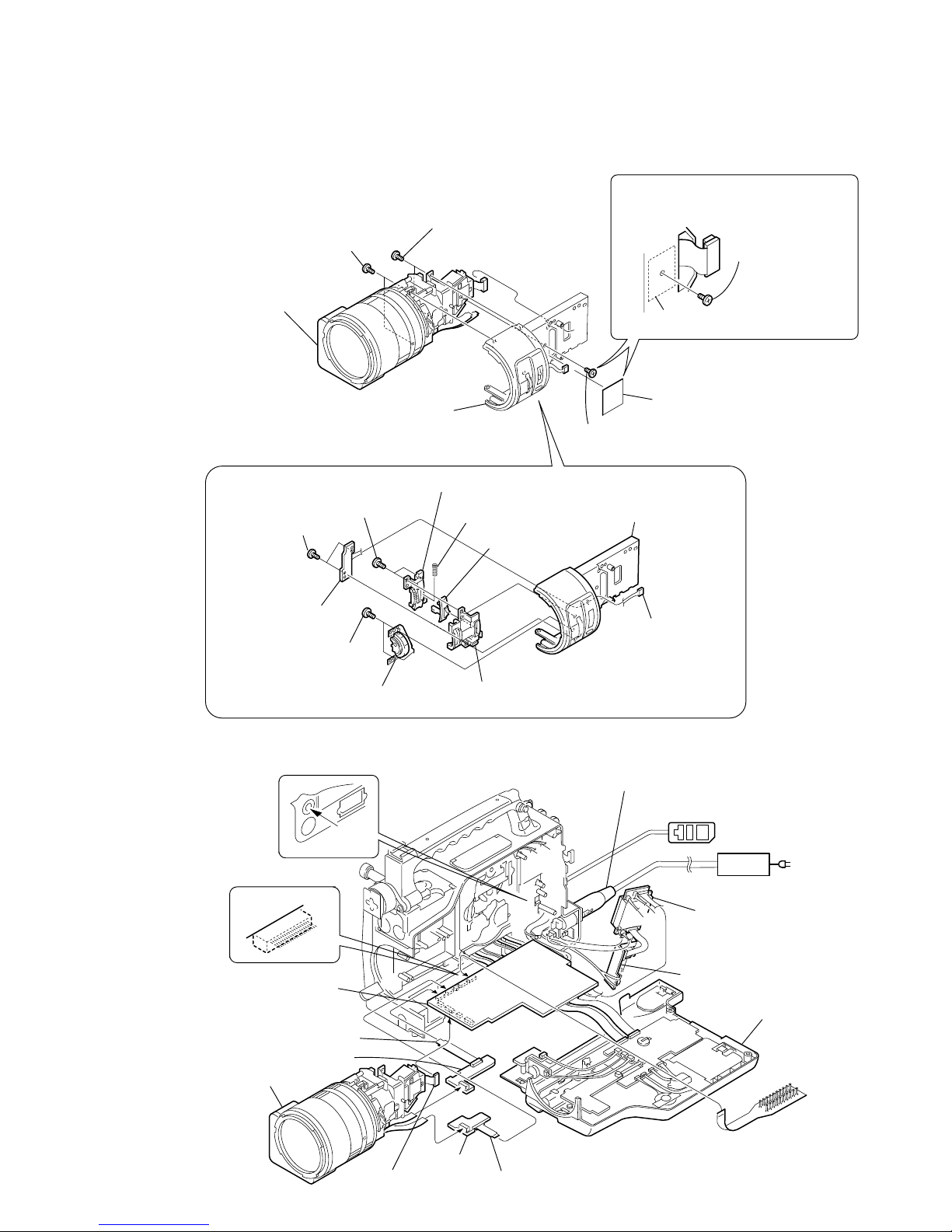
2-11
2-10.LENS BLOCK ASSEMBLY (LENS CABINET (R))
6
Lens block assembly
3
Two screws (M2 × 3),
lock ace, p2
5
Two screws (M2 × 4),
lock ace, p2
1
Two screws (M2 × 4),
lock ace, p2
0
Lens cabinet (R)
4
FC-074 board,
Harness (VF-071) (3P)
2
ND knob assembly
9
MF escutcheon
8
MF knob
7
Compression spping
6
MF knob holder
5
Lens cabinet
(R) assembly
4
Two screws (M2 × 4),
lock ace, p2
3
Two screws (M2 × 4),
lock ace, p2
B
A
B
A
VI-156
Board
AC IN
FP-242 flexible board (39P)
FP-243 flexible board (27P)
SW-343
SB-036
ON-001
NO-001
DD-146
CN007 20P
20
1
2
Screw (M2 × 4),
lock ace, p2
1
Harness fixed tape
Screw (M2
×
4),
lock ace, p2
When you want to remove screws, remove
this screw first. Also remove this screw last
when re-installing the parts.
CAUTION WHEN INSTALLING
AND REMOVING SCREWS
REMOVING LENS CABINET (R)
Harness (VF-071) (3P)
How to make the DC cable
(See page 2-1)
Regulated power supply
LANC
jack
Adjustment remote
commander (RM-95)
Cabinet (R) block assembly
CPC-13 jig
(J-6082-443-A)
[ VI-156 BOARD SERVICE POSITION]
DD-146 board
IN-057 board
VI-156 board
NO-001 board
CD-274 board (50P)
ON-001 board
Lens block assembly
12V
The position where the harness
tieing tape is attached.
Torgue : 1 kg
•
cm
or less
2-12
Connection to Check the CAMERA Section
To check the CAMERA Section, set the CAMERA to the "forced CAMERA power ON" mode.
Setting the “Forced CAMERA Power ON” mode
1) Select page: 0, address: 01, and set data: 01.
2) Select page: D , address: 10, set data: 01, and press
the PAUSE button of the adjustment remote
commander.
Exiting the “Forced CAMERA Power ON” mode
1) Select page: 0, address: 01, and set data: 01.
2) Select page: D , address: 10, set data: 00, and press
the PAUSE button of the adjustment remote
commander.
3) Select page: 0, address: 01, and set data: 00.
B
A
B
A
VI-156
Board
Control switch block (CF-1044)
Lens block assembly
VIDEO IN/OUT
AC IN
FP-242 flexible board (39P)
FP-243 flexible board (27P)
ON-001
NO-001
D
D-146
[SERVICE POSITION TO CHECK THE CAMERA SECTION]
VIDEO OUT
TV monitor
LANC jack
How to make the DC cable
(See page 2-1)
Regulated power supply
Adjustment remote
commander (RM-95)
12V
DD-146 board
IN-057 board
VI-156 board
ON-001 board
NO-001 board
JK-197 board
CD-274 board (50P)
Harness (VG-052) (12P)
2-13
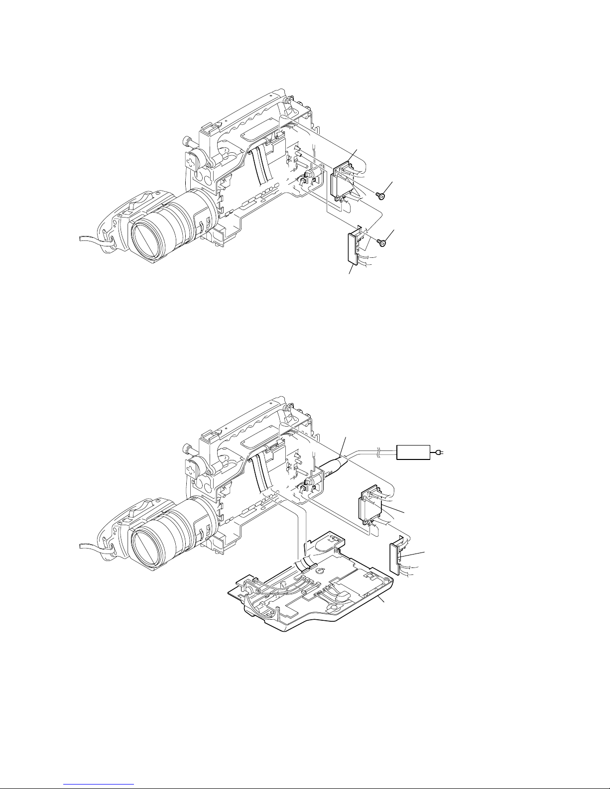
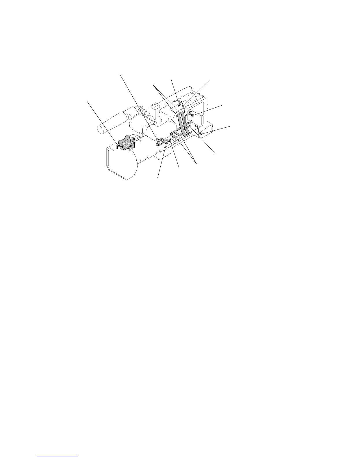
2-11.XL-003, VO-012, DV-031, RL-057 BOARDS
5
Two screws
(M3 × 8)
2
VO-012 board,
DV-031 board
4
RL-057 board,
LANC bracket
6
1
T wo screws
(M2
×
3)
lock ace, p2
3
Screw (M2 × 3)
lock ace, p2
7
XL-003 board, XLR bracket,
AU slide knob
REMOVING XL-003 BOARD
2-12.FS-082 BOARD, 4P CONNECTOR (WITH DC SW)
VI-156
Board
1
Four screws
(M2 × 4) lock ace, p2
3
Four screws
(M2 × 3) lock ace, p2
2
Front lower cabinet assembly
6
Harness (DC-064)
2
Remove the
two solderings
5
Two screws (M2.6 × 5),
spring bolt
4
FS-082 board, Harness
(FV-120) (6P), AUDIO VR knob
1
Screw
(M2 × 8)
4
4P connector
(with DC SW)
3
Micro switch,
Harness (ID-052) (6P)
REMOVING 4P CONNECTOR (WITH DC SW)
2-14
VI-156
Board
VF cable
ME-019 board
TH-010 board
SUB board
NO-001 board
ON-001 board
FS-082 board
CD-274 board (50P)
MAIN
board
XL-003 board
DD-146 board
IN-057 board
SE-343 board
VI-156 board
RL-057 board
LANC terminal
4P connector (with DC SW)
D
D
-1
4
6
M
E-019
S
W
-343
S
B
-036
GF
E
D
A
C
B
AC IN
12V
CPC-13 jig
(J-6082-443-A)
VF assembly
DXF-801 (DSR-250),
DXF-801CE (DSR-250P)
Harness
(MV-124) (7P)
Harness
(VM-068) (12P)
Harness
(VR-128) (5P)
Harness
(DX-050) (3P)
Harness
(VH-050) (12P)
Harness
(VX-050) (8P)
Harness
(DM-141) (4P)
Harness
(ID-052) (6P)
Harness
(FV-120) (6P)
Regulated power
supply
Adjustment remote
commander (RM-95)
Mechanism deck
Cabinet (R) block assembly
Lens block
assembly
FP-242 flexible
board (39P)
FP-243 flexible
board (27P)
A
Flexible board (from capstan motor) (18P)
B
Flexible board (from drum motor) (11P)
C
Harness (from loading motor) (2P)
D
Flexible board (from drum motor) (10P)
E
Harness (from cam motor) (2P)
F
FRV-008 flexible flat cable
(from MD-76 board) (21P)
G
FRV-008 flexible flat cable
(from MD-76 board) (21P)
[CONNECTION DIAGRAM FOR SERVICE POSITION (Mainly for voltage measurement and check)]
(TH-010, ME-19, MAIN, SUB, SW-343, DD-146, IN-057, VI-156, ON-001, NO-001, CD-274, XL-003, RL-057,
FS-082 boards, Mechanism deck)
How to make the DC cable
(See page 2-1)
2-15
The circuit boards contained in the mechanism deck and that in the zoom lens are not shown.
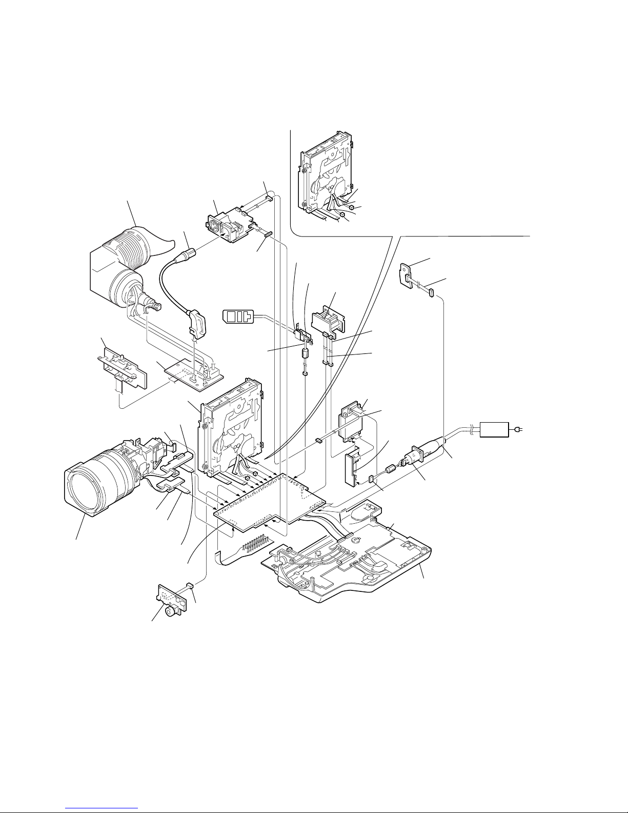
2-13.CIRCUIT BOARDS LOCATION
PD-126
(RGB DRIVE, TIMING GEN)
HP-129
(HEADPHONE OUT)
TH-010
(SIRCS (REAR))
KY-049
(VCR FUNCTION)
LL-010
(USER FUNCTION)
EJ-034
(EJECT)
INVERTER TRANSFORMER
UNIT
DC-095
(DC OUT)
XL-003
(CH1/CH2 MIC AMP)
RL-057
(LANC)
VO-012
(VIDEO OUT)
DV-031
(DV IN/OUT)
DD-146
(DC-DC CONVERTER)
IN-057
(DC IN)
MS-058
(MS CONNECTOR)
VI-156
CAMERA, DV/MS INTERFACE,
SERVO, REC/PB HEAD AMP,
AUDIO, DD CONV.
KP-011
(MENU SELECT)
AE-023
(USER FUNCTION)
SB-036
(USER FUNCTION)
ME-019
(MIC AMP, EVF OUT)
SW-343
(USER FUNCTION)
NO-001
(RELAY)
ON-001
(RELAY)
FS-082
(USER FUNCTION)
FC-074
(USER FUNCTION)
JK-197
(VIDEO/AUDIO IN/OUT)
SUB
MAIN
VL-034
(LIGHT)
PM-040
(MODE SELECT)
LED (A)
LED (B)
2-16E
2-14.FLEXIBLE BOARDS LOCATION
FVK-001
FSS-004
FRV-008
FP-243
FP-242
FP-245
FP-241
FKE-001
FVS-001
CONTROL SWITCH BLOCK
(EG-1044)
CONTROL SWITCH BLOCK
(CF-1044)
The flexible boards contained in the mechanism deck and that in the zoom lens are not shown.
5-33
6. V-COM Adjustment (PD-126 board)
Set the DC bias of the common electrode drive signal of LCD to the
specified value.
If deviated, the LCD display will move, producing flicker and
conspicuous vertical lines.
Mode VTR stop
Signal No signal
Measurement Point Check on LCD display
Measuring Instrument
Adjustment Page D
Adjustment Address A4
Specified Value The brightness difference between the
section A and section B is minimum.
Note: Perform “Bright Adjustment”, “Black Limit Adjustment”, “Contrast
Adjustment” and “Center Level Adjustment” before this adjustment.
Adjusting method:
Order Page
Address
Data Procedure
1 0 01 01 Set the data.
2 D B0 Write down the data.
3 D B0 CA Set the data, and press PAUSE
button.
4 D A4 Change the data so that the
brightness of the section A and
that of the section B is equal.
(The data should be “80” to
“BF”.)
5 D A4 Subtract 2 from the data.
6 D A4 Press PAUSE button.
7 D B0 Write the data that was written
down in the step 2.
8 D B0 Press PAUSE button.
9 0 01 00 Set the data.
7. White Balance Adjustment (PD-126 board)
Correct the white balance.
If deviated, the reproduction of the LCD screen may degenerate.
Mode VTR stop
Signal No signal
Measurement Point Check on LCD screen
Measuring Instrument
Adjustment Page D
Adjustment Address A8, A9
Specified Value The LCD screen should not be
colored.
Note1: Check the white balance only when replacing the following parts.
If necessary, adjust them.
1. LCD panel
2. Light induction plate
3. IC2101
Note2: Use the AC power adaptor.
Adjusting method:
Order Page
Address
Data Procedure
1 0 01 01 Set the data.
2 D A8 85 Set the data, and press PAUSE
button.
3 D A9 75 Set the data, and press PAUSE
button.
4 D A9 Check that the LCD screen is
not colored. If not colored,
proceed to step 10.
5 D A8 Change the data so that the LCD
screen is not colored.
6 D A8 Press PAUSE button.
7 D A9 Change the data so that the LCD
screen is not colored.
8 D A9 Press PAUSE button.
9 D A9 If the LCD screen is colored,
repeat steps 5 to 9.
10 0 01 00 Set the data.
A
A
A
A
B
B
B
B
Fig. 5-1-22.
5-34
Find the replacement parts in Section 5, “Repair parts list (exploded
views)” and attach or remove the parts in the follo wing order . When
replacing and re-attaching the parts, adjustments are sometimes
required. Follow the instructions of each item.
Note: Drawing numbers in each box of the chart refer to the numbers
assigned to each part in the exploded views of Section 5, “Repair
parts list”.
INFORMATION
Tape guide 1
(Drawing numbers: 710 to 714)
Cassette
compartment
(Drawing numbers:
722, 851)
FL motor block
(Drawing numbers: M905, 853 to 856)
GL arm S/T block
(Drawing numbers: 810 to 817)
Coaster S/T Block
(Drawing numbers: 801 to 802)
MIC base guide
(Drawing numbers: 702)
MIC base assembly
(Drawing numbers: 701, 703, 723, 724, CN004, S004)
Drum cap
(Drawing numbers: 721)
Drum assembly
(Drawing numbers: M901)
Tape support
(Drawing numbers: 717)
Pinch arm assembly
(Drawing numbers: 718 to 720)
Capstan cover
(Drawing numbers: 819)
Capstan motor
(Drawing numbers: M903)
Tape guide 8
(Drawing numbers: 710 to 714)
Tape guide 2
(Drawing numbers: 776 to 780)
Tape guide 7
(Drawing numbers: 776 to 781)
Guide guard
(Drawing numbers: 715)
Capstan cover
(Drawing numbers: 819)
Reel motor
(Drawing numbers:
M904)
Pendulum retainer
(Drawing numbers: 705)
Pendulum
retainer
(Drawing
numbers: 705)
Pendulum arm assembly
(Drawing numbers: 706)
Brake arm S/Ratchet brake T
(Drawing numbers: 707, 708, 709)
SBR slider
(Drawing numbers: 757)
Cam motor
(Drawing numbers: M902)
Idler gear A/B
(Drawing numbers: 751, 752)
Motor holder block
(Drawing numbers: 763, 764, M902)
TG2 arm/TG2 band block
(Drawing numbers: 766, 768, 771 to 775)
TG7 arm/TG7 band block
(Drawing numbers: 767, 769, 770, 775)
Sub-slider arm
(Drawing numbers: 761)
Sub-slider
(Drawing numbers: 758)
Main cam gear
(Drawing numbers: 755)
Coupling gear
(Drawing numbers: 762)
Sub-cam gear
(Drawing numbers: 756)
Pinch slider
(Drawing numbers: 760)
Loading drive lever
(Drawing numbers: 759)
Main slider
(Drawing numbers: 820)
Brake arm S
(Drawing numbers: 708)
Main slider arm
(Drawing numbers: 803)
Encoder cover
(Drawing numbers: 818)
MD-76 board
(Drawing numbers: 824, etc.)
Pendulum stopper assembly
(Drawing numbers: 805)
Encoder gear
(Drawing numbers: 754)
Reel table S/T
(Drawing numbers: 753)
Reel base retainer
(Drawing numbers: 829)
Reel base S/T block
(Drawing numbers: 822, 823, 827, 828)
FP-248 flexible board (condensation sensor)
(Drawing numbers: 821)
Page 5-35
Page 5-39
Page 5-40
Page 5-41
Page 5-41
Page 5-42
Page 5-43
Page 5-43 Page 5-43
Page 5-41
Page 5-42
Page 5-42
Page 5-43
Page 5-44
Page 5-45 Page 5-46
Page 5-46 Page 5-46
Page 5-46
Page 5-43
Page 5-48 Page 5-48
Page 5-49 Page 5-49
Page 5-48
Page 5-46
Page 5-46
Page 5-46 Page 5-46
Page 5-45
Page 5-42
Page 5-44
Page 5-38
Page 5-38
Page 5-38
Page 5-38
Page 5-43
Page 5-44 Page 5-44
Page 5-39 Page 5-42
Page 5-41
Page 5-50
Page 5-40
Page 5-38
Page 5-39
Page 5-39
Note: When removing the MD-76 board, all the parts in the shaded
boxes ( ) of the chart need to be removed.
5-2. MECHANICAL SECTION ADJUSTMENT
START

5-35
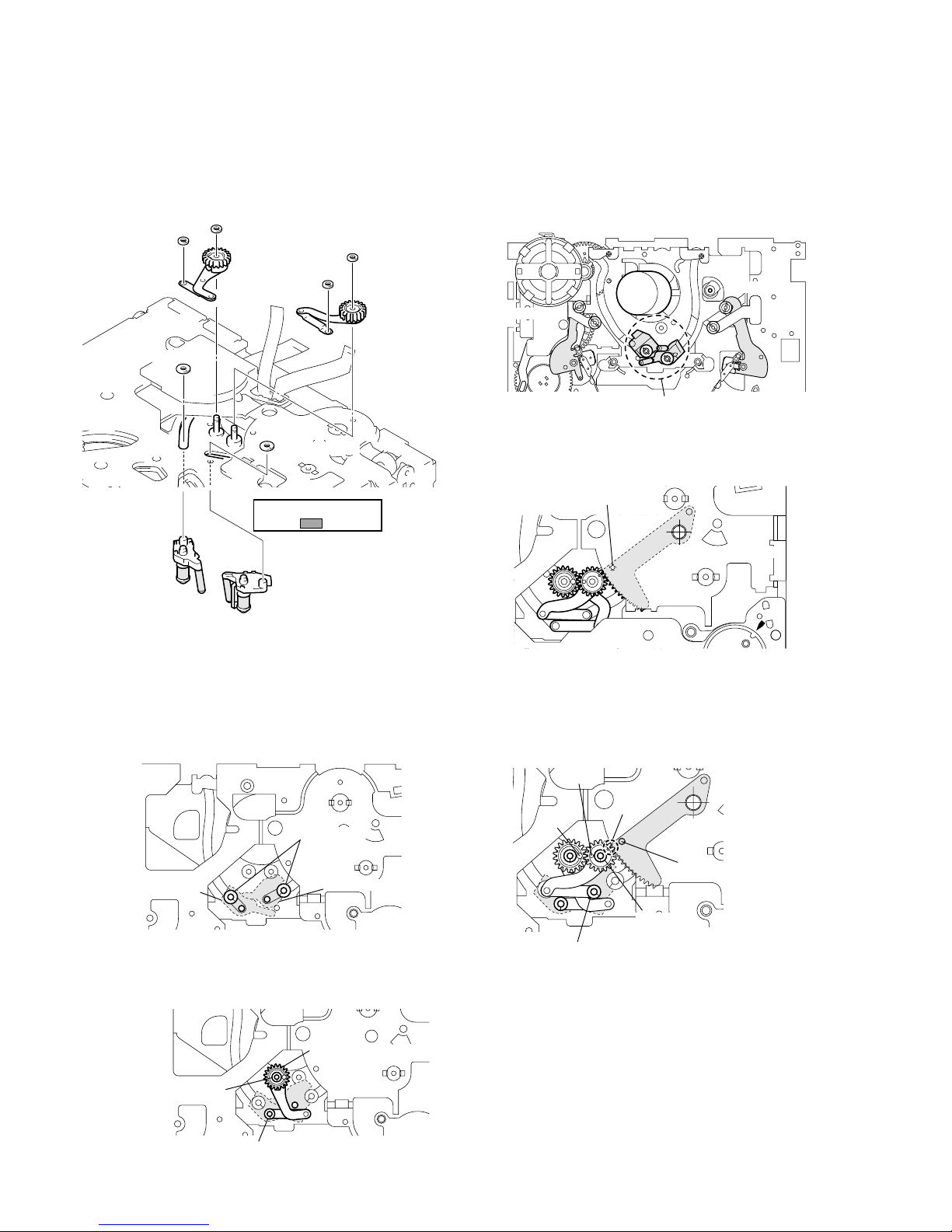
2-1-1. ASSEMBLY/DISASSEMBLY OF CASSETTE COMPARTMENT
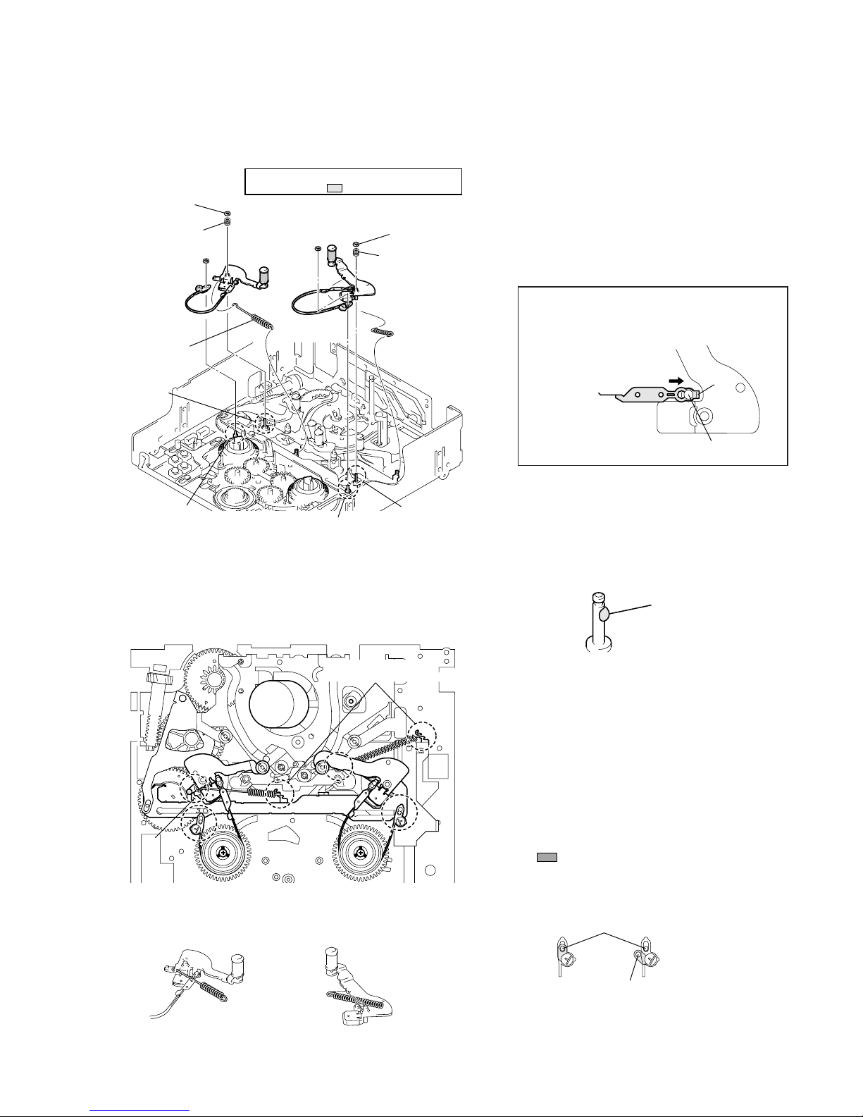
For details on disassembling the mechanism deck (R mechanism), refer to the Service Manual of the main unit in which the R mechanism is
mounted.
Before attaching or removing the cassette compartment, check the position of “L cassette”.
2-1-2. HO W TO LOAD/UNLOAD
[Using the regulated power supply]
Note: Make sure to remov e the connector of the cam motor from the board
of the main unit and apply +5V current.
[Manual: No cam motor]
Note: Remove the cam motor from the motor holder while referring to
“Information” on page 5-34.
5-2-1. PARTS REPLACEMENT AND PREPARATION FOR ADJUSTMENT
When attaching the cassette compartment,
move the reel selector slider in the direction of
arrow
B
to check the position of “L cassette”.
Bent portion
C
Positioning pin
Bent portion
C
SL shifter
Screw
Screw
Positioning pin
Cassette compartment
(Remove in the direction of arrow
A
.)
SL shifter
Bent portion
C
of the reel
selector slider should be
securely hooked on the
bent portion of the SL
shifter.
A
B
Tightening torque of cassette compartment
0.3432
±
0.0196N • m (3.5 ± 0.2 kg • cm)
Select the desired cassette position by pressing
the claw position.
Reel select slider
Do not touch the slider drive shaft.
When selecting a cassette position, be careful not to
touch the slider drive shaft because it can be easily
bent or broken.
Cam motor
Gray
White
Apply current from
the inlets of the connector.
Loading : Apply positive polarity (+) of power supply to the gray wire
and negative polarity (–) of power supply to the white wire.
Unloading: Apply negative polarity (–) of power supply to the gray wire
and positive polarity (+) of power supply to the white wire.
[Rear side of chassis]
Unloading
Loading
Coupling gear
Rotate the coupling gear by hand to load or unload.

5-36
2-1-3. About Mode Selector II
• About Mode Selector II
3-1. OUTLINE
This unit is a mechanism drive tool which supplements the
maintenance of each mechanism deck. Its functions are described
below.
1. Manual test
A mode which drives the motor only while the switch is ON. It
enables the operator to control the motor as desired.
2. Step test
A mode which drives the motor until the current condition detected
by the sensor changes to another condition. It enables the movements
made by the motor in each operation to be controlled while being
detected.
3. Auto test
A mode that checks if the mechanism operates normally according
to the condition shift table recorded in the unit for each mechanism
deck. All the conditions of the decks are checked through a series
of operations.
An error message is displayed and operations are stopped if incorrect
shifts and conditions are detected.
3-3. MODE SELECTOR II CONNECTION
3-2. MECHANISM CONDITION (POSITION)
SHIFTING ORDER LIST
After selecting the mechanism deck, select one of the two test modes
other than the auto test, and press the RVS or FF button to specify
the mechanism state (position).
R mechanism
CN2
Connector (white) 6P
Mode selector II
Alligator clip
Battery of NP-55, 77, etc. (power supply)
Connector (black) 6P
Relay boards
Mode selector conversion board (R)
Connector from the cam motor
A
Code
1
1
1
1
1
0
0
D
MD name
R mechanism
1
0
0
1
1
1
1
FWD / RVS
STOP
FF
REW
LE
DEW
ULE
7
6
5
4
3
2
1
C
0
1
1
0
1
1
1
B
1
1
0
0
0
0
1
5-37
5-2-2. PERIODIC CHECK
• Carry out the following maintenance and periodic checks not only to fully display the functions and performance of the set, but also for the
equipment and tape. After replacing, service the set as follows, regardless of the length of use.
2-2-1. CLEANING OF ROTARY DRUM ASSEMBLY
1. Press a wiping cloth (J-12) moistened with cleaning fluid (J-
11) against the rotary drum assembly gently , and clean it while
rotating the rotary drum assembly slowly with your finger in
the counterclockwise direction.
Note: Do not rotate the motor on power or rotate the rotary drum assembly
in the clockwise direction with your finger. The head tip will also be
damaged if the wiping cloth is moved perpendicularly against it.
Therefore, be sure to follow the above instructions when cleaning
the rotary drum assembly.
Note: When ov erhauling, refer to the checks above and replace parts.
Note: Greasing
Always use the specified grease. If the viscosity differs, various
problems may occur.
(Use SG-941 for all parts of the R mechanism.)
Check the quantity of grease when installing the parts which is
needed to apply the grease. When replacing these parts, make sure
to apply the specified amount of grease.
• FOIL (SG-941): Part No. 7-662-601-39
2-2-3. PERIODIC CHECKS
2-2-2. CLEANING OF TAPE PATH SYSTEM
1. Clean the tape pa th systems (TG1 to TG8 and capstan) and the
lower drum using a super fine applicator (J-13) moistened with
cleaning fluid.
Note: Make sure that no oil or grease of the link mechanisms sticks to the
super file applicator (J-13).
Note: Do not use a applicator moistened with alcohol to the other guide
cleaning. But clean the pinch roller using alcohol.
Cleaning cloth
Rotary
drum assembly
TG 3 Pinch roller
Capstan
TG 8
TG 7
TG 6TG 5TG 4
TG 2
TG 1
Cleaning of tape path surface
Capstan (Bearing)
Cam motor (worm block)
Abnormal noise
Back tension measurement
Brake system
FWD/RVS torque measurement
Gear
–
Cleaning and degaussing
of rotary drum assembly
Make sure that no oil gets
on the tape path surface.
Be careful of the oil.
X-3946-702-1 (M902)
Be careful of the oil.
a
500
–
–
–
–
–
a
a
5000
a
–
a
4500
–
–
–
–
–
a
a
4000
a
–
a
3500
–
–
–
–
–
a
a
3000
a
–
a
2500
Hours of Use (H)
Location of Maintenance
and Check
Remarks
–
–
–
–
–
a
a
2000
a
–
a
1500
–
–
–
–
–
a
a
1000
a
Performance
Confirmation
Driving
System
a
: Cleaning : Appling grease : Confirmation
5-38
5-2-3. PAR TS REPLACEMENT
• Precaution
For details on disassembling the cabinets, boards and other parts, refer to “Disassembly” of the Service Manual of each model. For details on
replacing parts (disassembly, assembl y) of the mechanism deck, refer to “Information” on page 5-34.
2-3-2. TAPE GUIDE 2/7
Disassembly/Assembly
When the tape guide 2/7 is replaced or attached, perform each
adjustment from Adjustment Start -3 of the flo wchart on page 5-52.
To attach or remove the tape guide, use the
screwdriver for the tape path (J-15). When
attaching the TG rollers, check the upward and
downward directions and that the TG roller to be
attached to the TG7 side is exclusiv ely for the TG7
side. Then attach the TG rollers to the chassis
shaft.
2-3-1. TAPE GUIDE 1/8 AND GUIDE GUARD
Disassembly/Assembly
When the tape guide 1/8 is replaced or attached, perform each
adjustment from Adjustment Start -2 of the flo wchart on page 5-52.
To attach or remove the tape guide, use the
screwdriver for the tape path (J-15). When
attaching the TG rollers, check the upward and
downward directions and attach them to the
chassis shaft.
The guide guard is fixed at each slit of the cassette
positioning shaft. To attach the guide guard, only
insert it into the right and left holes. To remov e it,
use a pair of tweezers as shown in the figure
below.
[TG2 side]
TG upper flange
TG roller
TG sleeve
TG sleeve
TG ring
TG ring
Compression coil
spring (TG)
Compression coil spring (TG)
TG2 arm block
[TG7 side]
TG upper flange
TG7 roller (Note that the shape is
different from that of the other rollers.)
Be careful not to touch the
tape guide ( part).
TG7 arm block
Face the side of the deepest
hole downward and insert the
roller into the shaft.
The lower flange of the TG7
roller is thicker than those of
the TG1, 2, and 8 rollers.
TG7 roller
[TG1 side]
(The components are the
same as on the TG8 side.)
Be careful not to touch the
tape guide ( part).
[TG8 side]
TG upper flange
TG roller
TG sleeve
TG ring
Compression coil
spring (TG)
Guide guard
Cassette positioning shafts
TG roller
Face the side of the
deepest hole downward
and insert the roller into
the shaft.
Insert a pair of tweezers into the
clearance of the chassis to release
the lock of the slit.
Lock of slit
5-39
2-3-4. REEL MOTOR
Disassembly/Assembly
Remove the claws of the FL motor assembly from hole A and hole
B
and remove the FL motor assembly. Then, remov e each gear , etc.
T o attach them, after attaching the gears, etc. to the FL motor assembly
and hook the positioning bosses of the FL motor block on holes
C
and D then fit the two claws in each hole A and B.
The worm gears are attached inside the
FL motor assembly . When attaching the FL
motor assembly, apply grease there.
2-3-5. FL MOTOR ASSEMBLY, GEAR A, GEAR B AND GEAR CD ASSEMBLY
Disassembly/Assembly
2-3-3. CAPSTAN COVER
Disassembly/Assembly
Gear A
Gear B
Positioning bosses
FL motor assembly
Hole
D
Hole
A
Hole
C
Hole
B
Gear CD assembly
Apply grease
(half size of one grain of rice).
Do not fasten
this screw.
CN 3
Screw
2
Fasten the screws
in order of 1, 2, 3.
Reel motor
Screw
1
Screw
3
Tightening torque of reel motor
0.0686 ± 0.0098 N • m (0.7 ± 0.1 kg • cm)
After inserting the flexible board
of the reel motor into CN3, attach
the reel motor and lock CN3.
Tightening torque of capstan cover
0.3432
±
0.0196 N • m (3.5 ± 0.2 kg • cm)
Capstan cover
Screw
Claw
1
2
Pass the two flexible boards
of the drum assembly through
the hole.
Insert the claw into the long hole
of the chassis and fix the cover
with the screw.
5-40
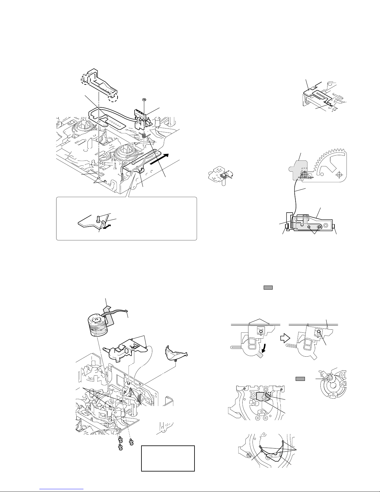
1 Attach the coaster S/T assembly to the chassis with a new
coaster stopper while being careful not to touch the tape guide.
Do the work while holding the drum side of each coaster.
2 Attach the GL arm T assembly. Fix the stop washers in the
correct position, using new stop washers.
3 Attach the GL arm S assembly while checking the phase of
each part. Fix the stop washers at the correct position, using
new stop washers.
Check each phase adjustment while referring to the above
figure.
Hole A of the GL gear T and hole B of the GL gear S must
face each other. Hole D of the loading arm assy must be aligned
with the hole of the chassis, and the endmost gear tooth of the
loading arm assy must face toward hole C of the GL gear S.
Assembly
With consideration for future assembly, check from the rear of the
chassis that the phase of the loading arm assy is aligned.
Move the TG2/7 arms to the loading position with the regulated power
supply or by hand while referring to page 5-35. Each coaster assembly
must be in the unloading position.
For the disassembling and assembling procedures of the GL gear,
GL helical torsion spring, etc., refer to page 5-50.
2-3-6. GL ARM S ASSEMBLY, GL ARM T ASSEMBLY, COASTER S ASSEMBLY AND COASTER T ASSEMBLY
Disassembly: Remove the parts in order of 1,2,3,4,5,6,7,8,9,0
1
4
3
7
8
0
9
6
2
5
Stop washer
Stop washer
Coater stop
washer
Coater stop
washer
GL arm S
assembly
Coaster stopper
Coaster S assembly
Coaster T
assembly
GL arm T
assembly
Do not touch the tape
guide ( part).
Coaster stopper
Unloading position
TG7 arm
TG2 arm
Loading arm assy
The phase must be aligned
with the hole of the chassis.
Coaster T assembly
Coaster stoppers
Coaster S assembly
Coaster stop washer
(The stop hole is larger.)
Stop washer
(The stop hole is smaller.)
GL arm T assembly
Stop washer
(The stop hole is smaller.
)
Coaster stop washer
(The stop hole is larger.)
Hole
A
Hole
B
Hole
C
Hole
D
Loading arm assy
5-41
Disassembly: Remove them in order of 1,2,3
For the disassembly and assembly procedures of the components of
the drum assembly, refer to page 5-51.
Assembly: Attach the parts while referring to the
disassembly procedure and the figure below.
(After assembling, adjust the tape path while referring to page 5-52
and thereafter.)
Disassembly/Assembly
For the disassembling and assembling procedures of the components
of the MIC base assembly, refer to page 5-50.
2-3-7. MIC BASE GUIDE, MIC BASE ASSEMBLY AND MIC BASE SPRING
Remove the six solders on the FP-104 flexible board from
the rear of the chassis. P ass the flexib le board through hole
A
and pull it out of the front side of the chassis while being
careful not to damage it. T o attach the fle xible board, perform
the steps of disassembly in reverse order.
Move the reel selector slider in the direction of arrow
B
and attach the MIC base assembly at the position of “S
cassette”. For the assembly of the MIC base spring, refer
to the figure.
Insert the side of the
shorter spring into the
hole of the holder and
hook the side of the
longer spring.
When attaching the MIC base guide,
lock the positioning pins, claw C,
and claw D in this order. Route the
flexible board into the clearance of
the MIC base guide.
2-3-8. DRUM CAP, DRUM ASSEMBLY AND TAPE SUPPORT
Assembly and disassembly of the drum assembly
When pulling the part in the direction of the arrow, the
claw is removed from the center shaft, then the right pin
and the drum cap are removed as shown in the figure on
the right. To attach the drum assembly, perform the
disassembly steps in reverse order.
Assembly and disassembly of the drum assembly
Assembly and disassembly of the tape support
3
2
1
4
Flexible board (7P)
Flexible board (10P)
Drum
assembly
Drum cap
Positioning pins
Tape suppor
t
Drum fixing screw assembly
(Fasten the screws in order
1, 2, 3
.)
Be careful not to remove
this together with the drum
cap.
1
2
3
Tightening torque of
drum assembly
0.02941
±
0.0049 N • m
(0.3
±
0.05 kg • cm)
Drum reference pins
Pins
Pin
Center shaft
Insertion hole of
flexible board (7P)
Insertion hole of
flexible board (10P)
The claw is hooked
on the sub-chassis.
The claws are
hooked under
the sub-chassis.
Positioning pin
Be careful that the 7P flexible board
does not interfere with the part.
MIC base guide
Claw
Claw
FP-104 flexible
board
(Remove the
six solders.)
Reel selector slider
MIC base spring
Positioning pins
Hole
A
MIC base
assembly
Stop washer
(Do not reuse.)
B
Select the desired cassette position by pressing the claw position.
Reel select slider
Do not touch the slider drive shaft.
When selecting a cassette position, be careful not to touch the
slider drive shaft because it can be easily bent or broken.
MD-76 board
Six solders
Temperature of tip
of soldering iron : 350
±
20 °C
Hold time : one second or shorter
Hole
A
MIC base guide
FP-104
flexible board
Clearance
Claw
D
Pins
Claw
C
MIC base assembly
Note: Do not hold the shaft when
selecting the reels.

5-42
2-3-10. CAPSTAN MOTOR
Disassembly/Assembly
(After assembling, adjust the tape path from page 5-52.)
2-3-9. PINCH ARM ASSEMBLY
Disassembly/Assembly
For the disassembling and assembling procedures of the tape retainer
and compression coil spring (tape retainer), refer to page 5-51.
Push roller A into the
groove as shown in the
figure. Insert roller B into
the claw. To remove the
pinch arm assembly, pull
out the pinch arm upward
while pushing the claw.
2-3-11. PENDULUM RETAINER AND PENDULUM ARM ASSEMBLY
Disassembly: Remove them in order of 1,2,3
(To attach them, perform the disassembly steps in reverse order.)
Notes during assembly
When assembling or disassembling the pendulum arm assembly,
be careful of the following.
Attach the pendulum retainer to shaft B. Be careful of the positions
of the pendulum stopper at the rear of the chassis and shaft A of the
pendulum arm.
1
2
3
Screw
Tightening torque of pendulum retainer
0.3432
±
0.0196 N • m (3.5 ± 0.2 kg • cm)
Pendulum retainer
(Remove in the direction
of the arrow.)
Pendulum arm
assembly
Shaft
Positioning boss
Shaft
B
Shaft
A
Shaft
B
Hole
E
D
F
[Rear side of pendulum retainer]
Insert tip
D
of the pendulum
arm into hole
E
of the pendulum
retainer and insert the pendulum
into shaft
C
.
Shaft
C
Shaft
C
Slide the pendulum arm in
the direction of arrow
F
an
d
attach it to the chassis.
Shafts
B
Shafts
B
Cannot be removed.
Can be removed.
Pendulum stopper
Shaft
A
of the pendulum
must be in this position.
Capstan motor
Screw
Tightening torque of capstan motor
0.1961
±
0.0196 N • m (2.0 ± 0.2 kg • cm)
Be careful not to touch the
motor shaft ( part).
Roller
B
Roller
A
Pinch arm assembl
y
Claw
Roller
B
Roller
A
Claw
5-43
Disassembly/Assembly
(Do not touch the TG band block.)
When the reel table assembly is replaced or attached, perform each
adjustment from Adjustment Start -1 of the flo wchart on page 5-52.
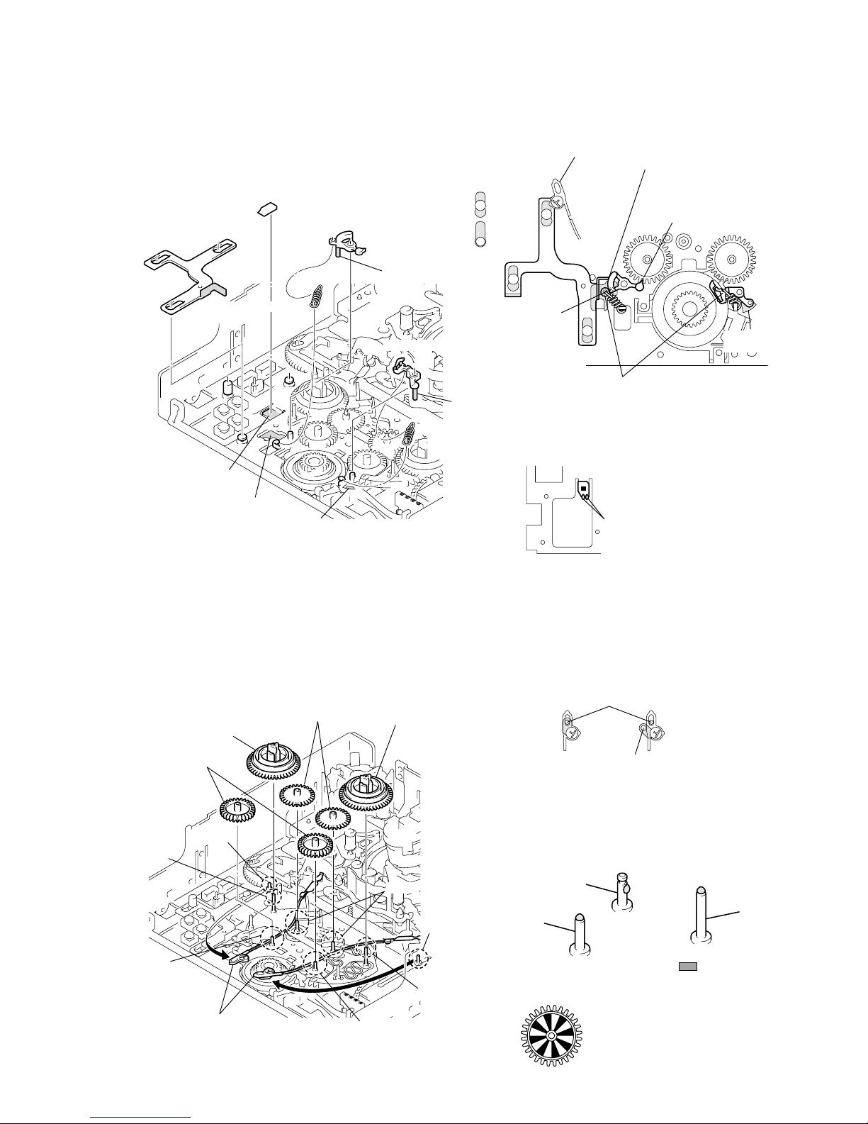
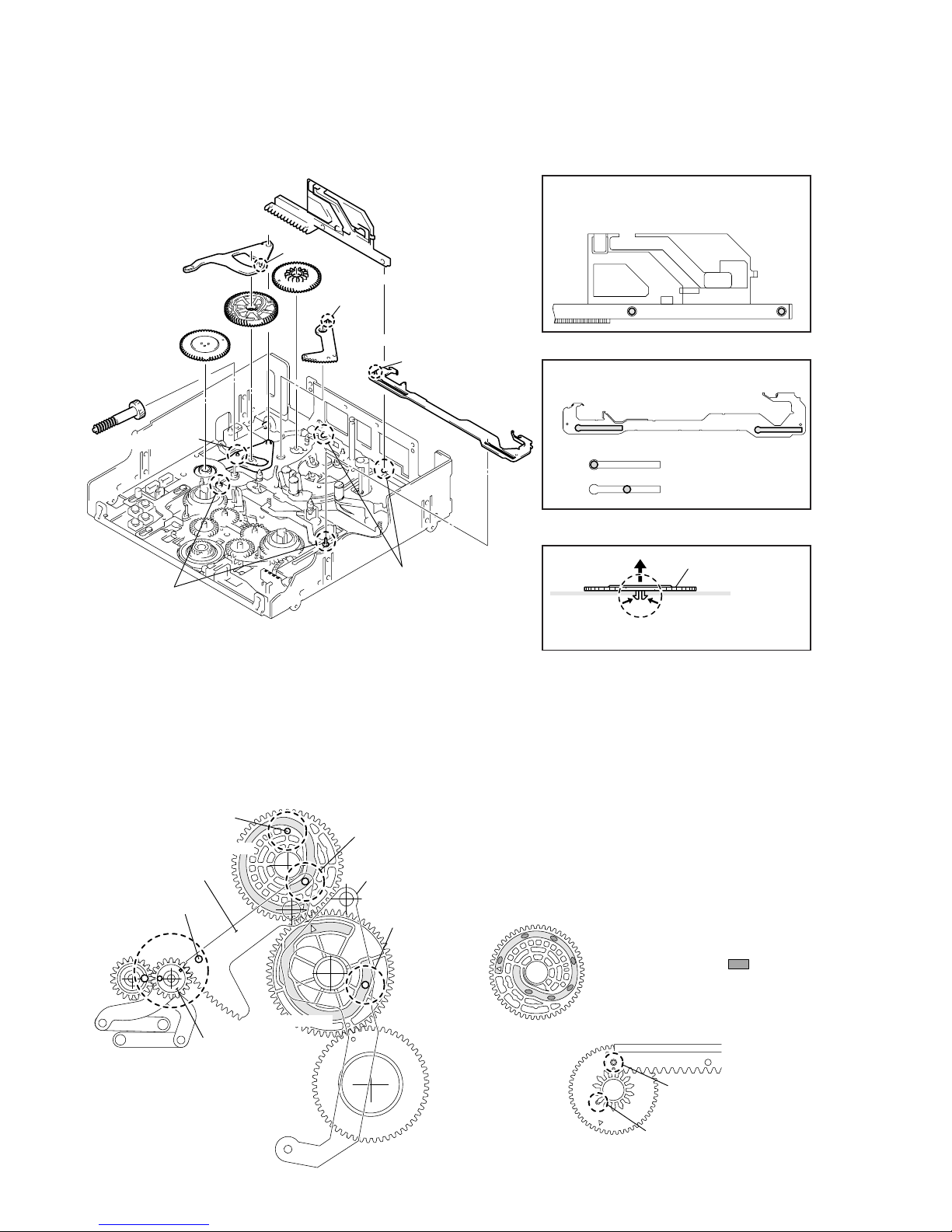
2-3-13. REEL TABLE ASSEMBLY, IDLER GEAR A ASSEMBLY AND IDLER GEAR B
Disassembly: Remove them in order of 1,2,3,4
(To attach them, perform the disassembly steps in reverse order.)
2-3-12. BRAKE ARM S, RATCHET BRAKE T, TENSION COIL SPRING (BRAKE), SBR SLIDER AND FP-248 FLEXIBLE
BOARD (CONDENSATION SENSOR)
Checks before work
The TG band winds around the slit of the reel table assembly. Before
removing the reel table assembly, clear off the TG band while
referring to the left figure. When attaching the TG band, be sure to
use new stop washers.
When attaching each gear, apply grease to each fixing shaft. Apply
grease of half the size of one rice grain to the top side of shaft C.
When attaching the idler gear A assembly, be careful not to apply
grease to the reflection panel.
Shaft
E
Shaft
A
Shaft
B
Shaft
B
Shaft
A
Shaft
D
Shaft
C
Clear off the stop washers of
the adjuster side of the TG
band in advance as shown
in the figure.
Idler gear A
assemblies
IReel table assembly
Idler gears B
Reel table assembly
Apply grease to part.
(half size of one grain of rice)
Shaft
B
Shaft
A
Shaft
C
Good Not good
Shaft D or
E
When attaching the TG band, the part also
must be inserted into shaft
D
or E.
When attaching the idler gear
A assembly, be careful not to
apply grease to the reflection panel.
1
2
1
4
3
2
Shaft
B
Hole
A
C
Shaft
A
Hole
B
FP-248 flexible board
(Condensation sensor)
SBR slider
Brake arm S
Tension coil spring
(brake)
Ratchet brake T
Tension coil
spring (brake)
Clean here
with alcohol.
Remove the SBR slider
while being careful not
to touch the adjuster.
Portion
C
of the SBR slider
and brake arm S must run
close to each other.
The idler gear
A
assembly
must be engaged with the
gear teeth.
Cannot be
removed.
Can be
removed.
Insert shaft
A
into hole A.
Insert shaft
B
into hole B.
Hook the hook of the spring on
the brake side from underneath.
When attaching the FP-248 flexible
board, scrape the contact surface
with a swab to stick the flexible
board to the chassis.
Do not touch the sensor block
(black area).
Two solders
Temperature of tip of soldering iron:
350
±
20
°C
Hold time:
one second or shorter
5-44
1 Move the reel selector slider in the direction of arrow A to
check that the reel selector lever is “L cassette”. At this position,
attach the reel base T assembly . The gear teeth must be engaged
as shown in the figure.
2 Move the reel selector slider in the direction of arrow B and
switch the reel selector lever to “S cassette”. At this position,
attach the reel base S assembly. The gear teeth (circled by a)
must be engaged as shown in the figure.
3 Attach the reel base retainer.
2-3-14. REEL BASE RETAINER, REEL BASE T ASSEMBLY AND REEL BASE S ASSEMBLY
(REEL LOCK RELEASE BLOCK AND REEL LOCK RELEASE SPRING)
Disassembly: Remove them in order of 1,2,3
(Refer to Assembly, too.)
2-3-15. CAM MOTOR, MOTOR HOLDER
Assembly: Attach them in order of 1,2,3
Disassembly/Assembly
[Rear side of motor holder]
The motor holder is fixed by the two
screws and claw B at the rear. To
remove it, push claw B in the direction
of the arrow from the rear of the
chassis. Note that positioning pins
D
are easy to break when attaching the
motor holder. Apply grease (half size
of one grain of rice) to the two
parts shown in the right figure.
[Front side of motor holder]
While spreading claws A in the
direction of the arrow, pull out the cam
motor upward. To attach it, push the
cam motor into the motor holder and
route the two wires of the cam motor
into claw C.
When attaching the TG2 control arm,
claw E must be inserted into the hole
of the TG2 control arm.
Checks before disassembly and assembly
The cam motor is fixed on the motor holder by the four
claws. Releasing the four claws enables the cam motor to
be removed without removing the motor holder from the
chassis. When attaching the cam motor, be careful of the
assembling direction (the label must face toward the front).
If the phase of the gear, etc. moves when removing the
motor holder, refer to page 5-40.
Cam motor
Label
Screw
Motor holder
(Release claw
B
at the rear.)
Apply grease to
the three parts
and tip.
(half size of one
grain of rice for
each part)
Positioning holes of pin
D
Tightening torque of motor holder
0.1961
±
0.0196 N • m
(2.0
±
0.2 kg • cm)
120
°
Screw
120
°
120
°
Claws
C
Claws
A
Claw
E
Pins
D
Claws
A
Pins
D
Claws
A
Claws
A
Claw
C
Claw
B
Pins
D
Pins
D
1
2
3
Reel base retainer
(Remove in reverse
order of assembly.)
Reel base
T assembly
Reel base S assembly
Reek lock release block
Reel lock release spring
This shaft hinders removing or
attaching the reel base S assembly.
Do the work while being careful not
to touch it.
Stop
washer
Not goodGood
A
Reel base T assembly
Reel selector slide
r
Reel selector lever
B
Reel base S assembly
The gear teeth circled
by aare engaged.
Attach in order of
1, 2
.
(Attach to the slits.)
1
2
Fixing state
Note: Do not hold the shaft when selecting the reels.
5-45
2-3-16. TG2/7 ARM BLOCK, TG2/7 BAND BLOCK AND TENSION COIL SPRING (TG2)/(TG7)
Disassembly: Remove them in order of 1,2,3,4
For the disassembling and assembling procedures of the assembly
components of the TG2/TG7 arm, refer to page 5-51.
Disassembly of the band TG2/TG7 assembly
When pulling portion E of the TG2 or TG7 band in the
direction of the arrow, a clic k sound is heard as the band
is removed. To attach the bands, pull out the opposite
side to portion E to lock.
Notes during work
Be careful when handling the TG arm and the peripheral parts.
• T wisting and bending of the band block and tension coil spring
• Dirt and scratches of the tape guide
• Loss of the compression coil spring (TG)
Do not reuse removed stop washers.
Assembly: Attach them while referring to figure above
or below and the descriptions.
When these parts are replaced or attached, perform each adjustment
from Adjustment Start -3 of the flowchart on page 5-52.
1 Apply grease to the top side of the fixing shaft (A or B) of
the TG arm. (Fig. 1)
1
1
4
2
3
3
2
4
Stop washer
Compression
coil spring (TG)
TG2 arm
assembly
TG7 arm bloc
k
Tension coil
spring (TG7)
Shaft
B
Tension coil
spring (TG2)
Stop washer
Stop washer
Compression coil
spring (TG)
Shaft
A
Shaft
C
Shaft
D
Stop washer
Be careful not to touch
the tape guide ( part) and TG band block.
Band TG2/TG7 assembly
Shaft
E
H
C
F
G
D
Sub-slider
Hook each spring on
the second hook from above
Half size of one grain of rice
[TG2 side] [TG7 side]
Hook the spring from the inside
and put it under the TG band.
Hook the spring from the outside
and put it under the arm.
Good
This part also must be
inserted into the shaft.
Not good
Fixing shaft C or D
2 Attach the TG band assembly to the TG arm assembly . (Fig. 2)
Be sure that the felt sides of the TG band face toward the reel
tables so that they surround the respective reel tables.
3 Attach the tension coil spring to the TG arm assembly . (Fig. 3,
4)
• Hook the spring of the tension coil spring (TG2) from the
inside and put it under the TG band. (Fig. 3-F, 4)
• Hook the spring of the tension coil spring (TG7) from the
outside and put it under the TG7 band. (Fig. 3-G, 4)
4 Attach the TG arm block to the shaft (A or B) and attach the
tension coil spring to the second hook. When attaching the TG2
arm, the part must be at the left of portion H of the slider .
(Fig. 3)
5 Attach the adjuster of the TG band to shafts C and D.
6 Fix the TG band and TG arm with new stop washers. When
attaching the TG arm, do not forget to attach the compression
coil spring (TG). (Fig. 1)
Fig. 1
Fig. 2
Fig. 3
Fig. 4
5-46
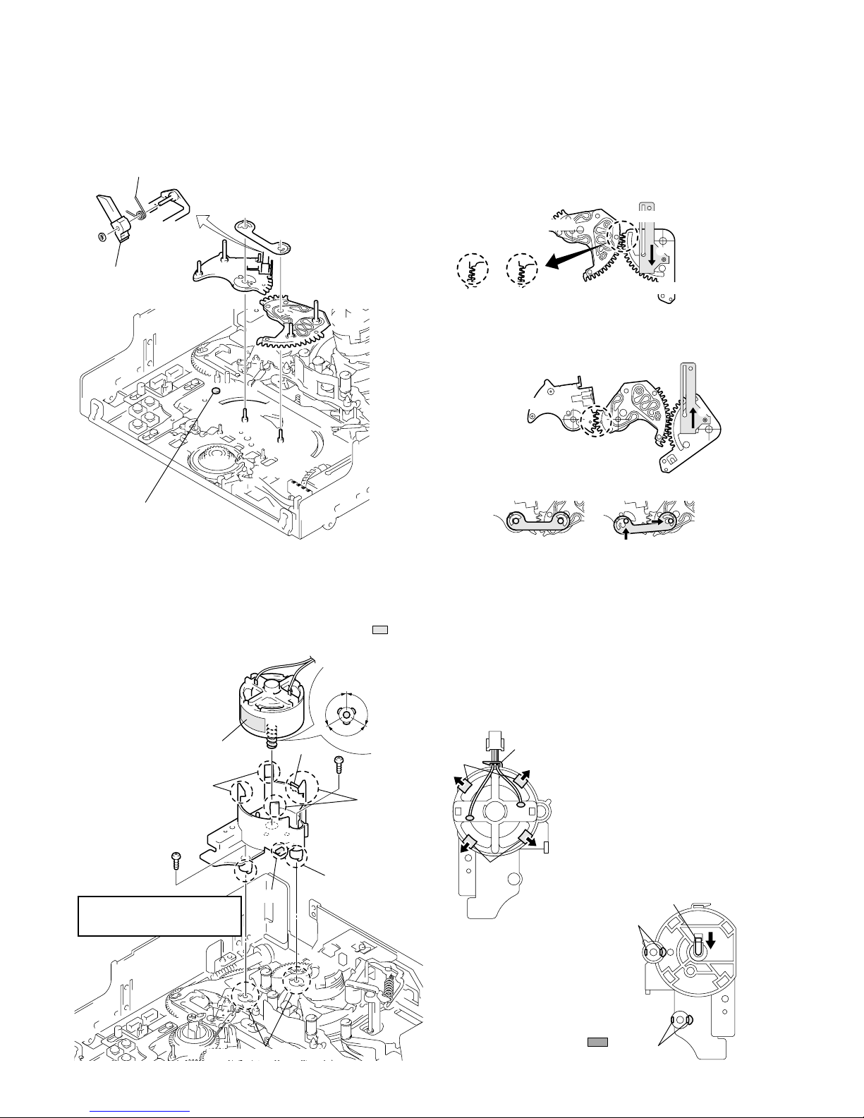
Disassembly of the pinch slider
Check before work
When attaching the parts described in this section, various phase
adjustments are required. Before work, refer to page 5-48 and check
the reference phases.
Assembly: Attach them while referring to the figure above or below and the descriptions.
Move the pinch slider to the leftmost end, and slide
it upward and remove it when two shafts A are
superimposed on the holes of the pinch slider.
Move the sub-slider to the rightmost and remove
it from two shafts B.
Disassembly: Remove them in order of 1,2,3,4,5,6,7,8
2-3-17. SUB-SLIDER ARM, SUB-SLIDER, ENCODER GEAR, MAIN CAM GEAR, COUPLING GEAR, SUB-CAM GEAR,
PINCH SLIDER AND LOADING ARM ASSY
1 Attach the loading arm assy. (Refer to the figure above.)
The phases of the GLS gear and GL T gear must match and the
positioning hole G of the loading arm assy must be
superimposed on the hole of the chassis. (Fig. 5)
2 Attach the pinch slider. (Fig. 1, 2)
3 Apply grease to the groove at the rear of the sub-cam gear.
(Fig. 6)
After applying, adjust the phase of the sub-cam gear to that of
the pinch slider. (Fig. 7)
Phase pin D of the loading arm assy must be inserted into the
groove at the rear of the sub-cam gear. (Fig. 5, 7)
Disassembly of the encoder gear
Disassembly of the sub-slider
2
4
6
1
3
7
8
Pinch slider
Sub-cam gear
5
Phase pin
D
Loading arm assy
Phase pin
F
Sub-slider
Shafts
A
Shafts
B
Phase
pin
E
Encoder gear
(A claw is hooked.)
Main cam gear
Sub-slider arm
Coupling gear
This can be removed.
This cannot be removed.
Pull out the encoder gear
upward while pushing into
the claw.
Encoder gear
1
Phase adjustment hole
H
Sub-cam gear
Loading arm assy
Positioning hole
G
GL T gear
GL S gear
Main cam gear
Phase pin
M
Main slider arm
Phase pin
D
[Rear side of chassis]
Sub-cam gear (rear side)
Apply grease to the seven parts.
(half size of one grain of rice for each part)
Sub-cam gear
(front side)
Phase adjustment hole
H
matches the hole of the
chassis.
Check phase pin
D
through this hole
Pinch slider
Fig. 1
Fig. 2
Fig. 3
Fig. 4
Fig. 5
Fig. 6
Fig. 7
 Loading...