

Sony DVCAM DSR-11, RMT-DS11 Service Manual
SERVICE MANUAL
Ver 1.0 2000. 11
US Model
Canadian Model
AEP Model
UK Model
Australian Model
New Zealand Model
DIGITAL VIDEO CASSETTE RECORDER
SPECIFICATIONS
– Continued on next page –
R MECHANISM
DSR-11
RMT-DS11
System
Recording format DVCAM/DV (SP) format, rotating
2-head helical scan, digital
component recording
Video signal EIA STANDARD, NTSC color
system
CCIR STANDARD, PAL colour
system
Video
Quantification 8-bit
Standardization
frequency NTSC:
13.5 MHz (4:1:1 Component)
PAL:
13.5 MHz (4:2:0 Component)
Audio
Quantification 12-bit (non-linear) or 16-bit (linear)
Standardization
frequency 32 kHz (12-bit recording) or
48 kHz (16-bit recording)
Usable cassettes Standard-DVCAM cassettes and
Mini-DVCAM cassettes
Recording time Standard cassette
DVCAM:
184 minutes (PDV184)
180 minutes (DV270)
DV: 270 minutes (PDV184/
DV270)
Mini cassette
DVCAM: 40 minutes (PDVM40/
DVM60)
DV: 60 minutes (PDVM40/
DVM60)
(We recommend that you use the
DVCAM cassettes.)
Clock
Quartz locked
Power back-up Back-up duration: up to one month
(after a 10-hour charge)
Inputs and outputs
Video input Phono jack
Input signal: 1 Vp-p
(75 ohms unbalanced)
Video output Phono jack
Output signal: 1 Vp-p
(75 ohms unbalanced)
S video input Mini DIN 4-pin
Luminance signal: 1 Vp-p
(75 ohms unbalanced)
Chrominance signal:
0.286 Vp-p (NTSC)
0.3 Vp-p (PAL)
(75 ohms unbalanced)
S video output Mini DIN 4-pin
Luminance signal: 1 Vp-p
(75 ohms unbalanced)
Chrominance signal:
0.286 Vp-p (NTSC)
0.3 Vp-p (PAL)
(75 ohms unbalanced)
Audio input Phono jack (L, R)
Input level: 2 Vrms (full bit)
Input impedance: more than
47 kohms
Audio output Phono jack (L, R)
Output level: 2 Vrms (full bit)
Output impedance: less than
10 kohms
Control S input Minijack
LANC input/output
Stereo mini-mini jack
DV input/output 4-pin jack
General
Power consumption
15 W (during playback)
Peak inrush current
Hot switching inrush current,
measured in accordance with
European standard EN55103-1:
6 A (230V)
Operating temperature
5 °C to 40 °C (41 °F to 104 °F)
Storage temperature
–20 °C to +60 °C (–4 °
F to +140
°F)
– 2 –
1. Check the area of your repair for unsoldered or poorly-soldered connections. Check the entire board surface for solder
splashes and bridges.
2. Check the interboard wiring to ensure that no wires are
“pinched” or contact high-wattage resistors.
3. Look for unauthorized replacement parts, particularly transistors, that were installed during a previous repair. Point them
out to the customer and recommend their replacement.
4. Look for parts which, though functioning, show obvious signs
of deterioration. Point them out to the customer and recommend their replacement.
SAFETY CHECK-OUT
After correcting the original service problem, perform the following
safety checks before releasing the set to the customer.
5. Check the B+ voltage to see it is at the values specified.
6. Flexible Circuit Board Repairing
• Keep the temperature of the soldering iron around 270 ˚C
during repairing.
• Do not touch the soldering iron on the same conductor of
the circuit board (within 3 times).
• Be careful not to apply force on the conductor when soldering or unsoldering.
ATTENTION AU COMPOSANT AYANT RAPPORT
À LA SÉCURITÉ!
LES COMPOSANTS IDENTIFIÉS P AR UNE MARQUE 0
SUR LES DIAGRAMMES SCHÉMA TIQUES ET LA LISTE
DES PIÈCES SONT CRITIQUES POUR LA SÉCURITÉ
DE FONCTIONNEMENT. NE REMPLACER CES COMPOSANTS QUE PAR DES PIÈCES SONY DONT LES
NUMÉROS SONT DONNÉS DANS CE MANUEL OU
DANS LES SUPPLÉMENTS PUBLIÉS PAR SONY.
SAFETY-RELATED COMPONENT WARNING!!
COMPONENTS IDENTIFIED BY MARK 0 OR DOTTED
LINE WITH MARK 0 ON THE SCHEMA TIC DIAGRAMS
AND IN THE PARTS LIST ARE CRITICAL TO SAFE
OPERATION. REPLACE THESE COMPONENTS WITH
SONY PARTS WHOSE PART NUMBERS APPEAR AS
SHOWN IN THIS MANUAL OR IN SUPPLEMENTS PUBLISHED BY SONY.
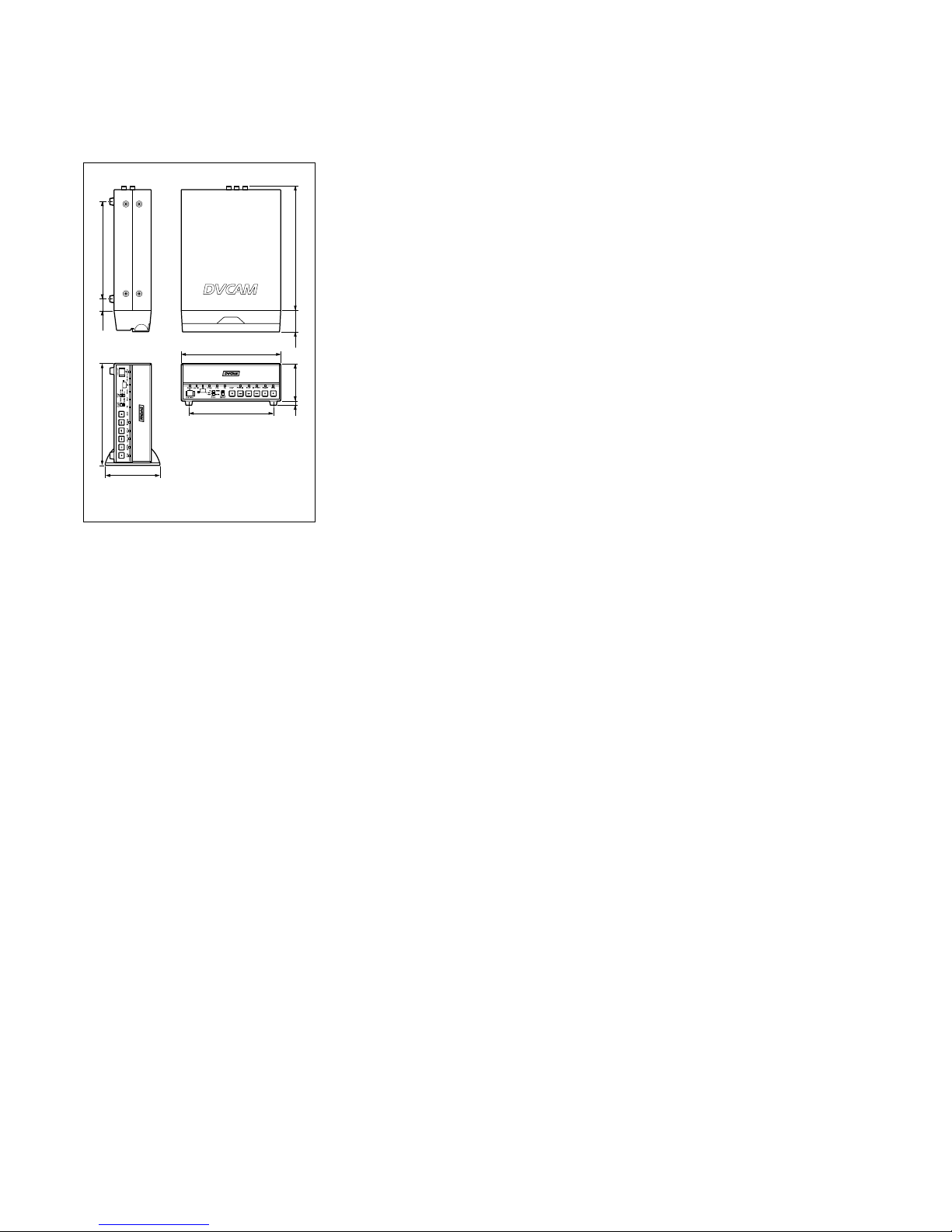
Dimensions Approx. 180 × 73 × 265 mm
(7
1
⁄8 × 2 7⁄8 × 10 1⁄2 inches)
(w/h/d, including projecting parts
and controls)
Mass Approx. 2.7 kg (5 lb 15 oz)
Supplied accessories
Remote Commander (1)
Size AA (R6) batteries (2)
AC power adaptor (1)
Power cord (1)
Rack (1)
Cleaning cassette (1)
Operating instructions
Design and specifications are subject to change
without notice.
Unit: mm (inches)
184 (7
1
/
4
)
18.5 (
3
/
4
)185 (7
3
/
8
)
226.1 (9)
180 (7 1/8)
151 (6)
38.4 (1
9
/
16
)
4 (
3
/
16
)
69 (2
3
/
4
)
110 (4
3
/8)

– 3 –
TABLE OF CONTENTS
Section Title Page Section Title Page
SERVICE NOTE ............................................................... 5
1. Note for Repair ............................................................ 5
SELF-DIAGNOSIS FUNCTION ..................................... 6
1. Self-diagnosis Function............................................... 6
2. Self-diagnosis Display................................................. 6
3. Service Mode Display ................................................. 6
4. Self-diagnosis Code Table .......................................... 7
1. GENERAL
Features ................................................................................ 1-1
Location and Function of Parts ............................................. 1-1
Notes on Video Cassettes ..................................................... 1-3
Preparations .......................................................................... 1-3
Playback ................................................................................ 1-4
Recording .............................................................................. 1-8
Installing the Unit Vertically ................................................... 1-9
Operating the Menus............................................................. 1-9
Troubleshooting ..................................................................... 1-12
Alarm Messages.................................................................... 1-12
Notes on Use ......................................................................... 1-12
Compatibility of DVCAM and DV Format.............................. 1-13
2. DISASSEMBLY
2-1. Upper Case ................................................................. 2-1
2-2. Front Panel Assembly ................................................. 2-1
2-3. VD-031 Board.............................................................. 2-1
2-4. DC/DC Converter Unit................................................. 2-1
2-5. HD-024 Board ............................................................. 2-2
2-6. Mechanism Deck......................................................... 2-2
2-7. JC-20 Board ................................................................ 2-2
2-8. RP-234 Board.............................................................. 2-2
2-9. Circuit Boards Location............................................... 2-3
3. BLOCK DIAGRAMS
3-1. Overall Block Diagram 1 ............................................. 3-1
3-2. Overall Block Diagram 2 ............................................. 3-3
3-3. Overall Block Diagram 3 ............................................. 3-5
3-4. Overall Block Diagram 4 ............................................. 3-7
3-5. Power Block Diagram 1............................................... 3-9
3-6. Power Block Diagram 2............................................... 3-11
3-7. Power Block Diagram 3............................................... 3-13
3-8. Power Block Diagram 4............................................... 3-15
4. PRINTED WIRING BOARDS AND
SCHEMATIC DIAGRAMS..................................... 4-1
4-1. Frame Schematic Diagram (1/2)................................. 4-3
Frame Schematic Diagram (2/2)................................. 4-5
4-2. Printed Wiring Boards and Schematic Diagrams ....... 4-7
• RP-234 Printed Wiring Board ................................ 4-7
• RP-234 (REC/PB AMP 1) Schematic Diagram ..... 4-11
• RP-234 (REC/PB AMP 2) Schematic Diagram ..... 4-13
• JC-20 Printed Wiring Board ................................... 4-15
• JC-20 (VIDEO PB AMP) Schematic Diagram ....... 4-19
• JC-20 (VIDEO A/D CONVERTER)
Schematic Diagram................................................ 4-21
• JC-20 (CHROMA MIX) Schematic Diagram .......... 4-23
• JC-20 (AFC) Schematic Diagram .......................... 4-25
• JC-20 (VFD (VIDEO DSP, D/A CONVERTER))
Schematic Diagram................................................ 4-27
• JC-20 (SFD) Schematic Diagram .......................... 4-29
• JC-20 (TFD) Schematic Diagram .......................... 4-31
• JC-20 (DV INTERFACE) Schematic Diagram....... 4-33
• JC-20 (MECHANISM CONTROL 1)
Schematic Diagram................................................ 4-35
• JC-20 (MECHANISM CONTROL 2)
Schematic Diagram................................................ 4-37
• JC-20 (MODE CONTROL) Schematic Diagram.... 4-39
• JC-20 (AUDIO 1) Schematic Diagram................... 4-41
• JC-20 (AUDIO 2) Schematic Diagram................... 4-43
• JC-20 (POWER SUPPLY) Schematic Diagram .... 4-45
• VD-031 Printed Wiring Board ................................ 4-47
• VD-031 (INTERFACE) Schematic Diagram .......... 4-51
• VD-031 (VIDEO DECODER)
Schematic Diagram................................................ 4-53
• VD-031 (VIDEO OUTPUT) Schematic Diagram ... 4-55
• VD-031 (AUDIO) Schematic Diagram ................... 4-57
• VD-031 (Y/C SEPARATION)
Schematic Diagram................................................ 4-59
• HD-024 (HI CONTROL) Schematic Diagram ........ 4-61
• HD-024 (MATRIX KEY CONTROL, LED DRIVE)
Schematic Diagram................................................ 4-63
• HD-024 (UVIC) Schematic Diagram...................... 4-65
• HD-024 (DC/DC CONVERTER, CAPSTAN MOTOR
DRIVE, CAM MOTOR DRIVE)
Schematic Diagram................................................ 4-67
• HD-024 (DRUM MOTOR DRIVE, FL MOTOR DRIVE,
REEL MOTOR DRIVE) Schematic Diagram ......... 4-69
• HD-024 Printed Wiring Board ................................ 4-71
• MD-76 Printed Wiring Board.................................. 4-75
• MD-76 Schematic Diagram.................................... 4-77
• FR-175 Printed Wiring Board................................. 4-79
• FR-175 Schematic Diagram ................................... 4-81
• JA-006 Printed Wiring Board ................................. 4-83
• JA-006 Schematic Diagram ................................... 4-85
• JD-002 Printed Wiring Board and
Schematic Diagram................................................ 4-87
• DC-1492 Schematic Diagram ................................ 4-89
• DC-1492 Printed Wiring Board .............................. 4-91
4-3. Waveforms .................................................................. 4-95
4-4. Parts Location ............................................................. 4-99
5. ADJUSTMENTS
1. Bef ore Starting Adjustment ......................................... 5-1
1-1. Adjusting Items when Replacing Main Parts
and Boards .................................................................. 5-2
1-2. Information (Mechanical Section) ............................... 5-4
5-1. MECHANICAL SECTION ADJUSTMENTS ................ 5-5
5-1-1. Parts Replacement and Preparation
for Adjustment ........................................................ 5-5
1-1. Assembly/disassembly of Cassette Compartment ..... 5-5
1-2. How To Load/unload ................................................... 5-5
1-3. List of Service Tools .................................................... 5-6
1-4. About Mode Selector II ............................................... 5-7
5-1-2. Periodic Check ....................................................... 5-8
2-1. Cleaning of Rotary Drum Assembly....................... 5-8
2-2. Cleaning of Tape Path System .............................. 5-8
2-3. Periodic Checks ..................................................... 5-8
5-1-3. Parts Replacement................................................. 5-9
3-1. Tape Guide 1/8 and Guide Guard.......................... 5-9
3-2. Tape Guide 2/7....................................................... 5-9
3-3. Capstan Cover ....................................................... 5-10
3-4. Reel Motor .............................................................. 5-10
3-5. FL Motor Assembly , Gear A, Gear B and
Gear CD Assembly................................................. 5-10
3-6. GL Arm S Assembly, GL Arm T Assemb ly,
Coaster S Assembly and Coaster T Assembly ...... 5-11
3-7. MIC Base Guide, MIC Base Assembly and
MIC Base Spring .................................................... 5-12
3-8. Drum Cap, Drum Assembly and Tape Support ..... 5-12
3-9. Pinch Arm Assembly .............................................. 5-13
3-10. Capstan Motor........................................................ 5-13
3-11. Pendulum Retainer and
Pendulum Arm Assembly ....................................... 5-13

– 4 –
Section Title Page Section Title Page
3-12. Brake Arm S, Ratchet Brake T,
Tension Coil Spring (Brake), SBR Slider and FP-248
Flexible Board (Condensation Sensor) ................. 5-14
3-13. Reel Table Assembly, Idler Gear A Assembly
and Idler Gear B..................................................... 5-14
3-14. Reel Base Retainer, Reel Base T Assembly and
Reel Base S Assembly (Reel Lock Release Block
and Reel Lock Release Spring) ............................. 5-15
3-15. Cam Motor, Motor Holder....................................... 5-15
3-16. TG2/7 Arm Block, TG2/7 Band Block and
Tension Coil Spring (TG2)/(TG7) ........................... 5-16
3-17. Sub-slider Arm, Sub-slider, Encoder Gear ,
Main Cam Gear, Coupling Gear, Sub-cam Gear,
Pinch Slider and Loading Arm Assembly............... 5-17
3-18. Main Slider, Main Slider Arm and Pendulum
Stopper Assembly .................................................. 5-19
3-19. MD-76 Board and Encoder Retainer ..................... 5-20
3-20. Components of GL Arm S/T Assembly
(GL Arm Assembly , GL Helical Torsion Spring,
GL Gear)................................................................. 5-21
3-21. Components of MIC Base Assembly
(FP-104 Flexible Board, MIC Base)....................... 5-21
3-22. Components of Drum Assembly
(Motor FPC Assembly, Elastic Connector) ............ 5-22
3-23. Components of Pinch Arm Assembly (Tape Retainer,
Compression Coil Spring) ...................................... 5-22
3-24. Components of TG2/7 Arm Assembly (ET Magnet,
Magnet Holder) ...................................................... 5-22
5-1-4. Check and Adjustment ........................................... 5-23
4-1. Reel Table Height Check and Adjustment ............. 5-24
4-2. TG1/8 Height Check and Adjustment .................... 5-24
4-3. TG2/7 Height Check and Adjustment .................... 5-25
4-4. FWD/RVS Position Check and Adjustment ........... 5-25
4-5. Electric Tension Regulator Check and Adjustment
of TG2/7 Arm .......................................................... 5-26
4-6. FWD/RVS Back Tension Check and Adjustment .. 5-27
4-7. Preparation for Adjustment and
Tape Path Check .................................................... 5-28
4-8. Track Adjustment and Check
(Checking the RF Waveform) ................................ 5-29
4-9. Track Check ........................................................... 5-29
4-10. CUE/REV Check .................................................... 5-30
4-11. Curl Check and Adjustment ................................... 5-30
4-12. Rising Check .......................................................... 5-31
5-2. SERVICE MODE......................................................... 5-32
5-2-1. Adjusting Remote Commander.............................. 5-32
1. Used Adjustment Remote Commander ................. 5-32
2. Precautions Upon Using the Adjusting Remote
Commander............................................................ 5-32
5-2-2. Data Processing..................................................... 5-33
5-2-3. Service Mode ......................................................... 5-34
1. Setting the Test Mode ............................................ 5-34
2. Emergence Memory Address................................. 5-34
3. EMG Code (Emergency Code) .............................. 5-35
4. MSW Code ............................................................. 5-35
5. Bit Value Discriminatiion ........................................ 5-36
6. Record of Use Check ............................................. 5-37
5-3. VIDEO SECTION ADJUSTMENTS ............................ 5-38
3-1. Preparations Before Adjustment............................ 5-38
3-1-1. Equipment Used..................................................... 5-38
3-1-2. Connection of Equipment....................................... 5-39
3-1-3. Checking the Input Signals .................................... 5-40
1. S VIDEO Input ........................................................ 5-40
2. VIDEO Input ........................................................... 5-40
3-1-4. Adjustment Tapes................................................... 5-41
3-1-5. Input/output Level and Impedance ........................ 5-42
3-2. System Control System Adjustments .................... 5-43
1. Initializing the C, D, E Page Data .......................... 5-43
2. Input of C Page Initial Data .................................... 5-43
3. Input of D Page Initial Data .................................... 5-43
4. Input of E Page Initial Data .................................... 5-43
5. Modification of C, D, E, Page Data ........................ 5-43
6. C Page Table .......................................................... 5-44
7. D Page Table .......................................................... 5-45
8. E Page Table .......................................................... 5-45
9. Node Unique ID No. Input ...................................... 5-46
3-3. Servo and RF System Adjustments ....................... 5-48
1. Capstan FG Adjustment (HD-024 Board) .............. 5-48
2. PLL f0 Pre-adjustment (RP-234 Board) ................. 5-48
3. Switching Position Adjustment (HD-024 Board) .... 5-48
4. RF-AGC Adjustment (RP-234 Board) .................... 5-48
5. CLK DELAY and AEQ Adjustment
(RP-234 Board) ...................................................... 5-49
6. PLL f0 Final Adjustment (RP-234 Board) ............... 5-49
3-4. Video System Adjustments .................................... 5-49
3-4-1. JC-20 Board Adjustment ........................................ 5-49
1. VFD SPCK Adjustment (JC-20 Board) .................. 5-49
2. A/D Converter Reference Voltage
Adjustment (1) (JC-20 Board)................................ 5-49
3. A/D Converter Reference Voltage
Adjustment (2) (JC-20 Board)................................ 5-49
4. Y Signal Clamp Reference Voltage Adjustment
(JC-20 Board)......................................................... 5-50
5. CR Signal Clamp Reference Voltage Adjustment
(JC-20 Board)......................................................... 5-50
6. CB Signal Clamp Reference Voltage Adjustment
(JC-20 Board)......................................................... 5-50
7. AFC Preliminary Adjustment (JC-20 Board).......... 5-50
8. AFC Picture Frame Adjustment (JC-20 Board) ..... 5-50
9. AFC Adjustment (JC-20 Board) ............................. 5-50
10. Playback Y Level Adjustment (JC-20 Board) ........ 5-51
11. Playback C Level Adjustment (JC-20 Board) ........ 5-51
3-4-2. VD-031 Board Adjustment ..................................... 5-52
1. Decoder Free Run Adjustment (NTSC)
(VD-031Board) ....................................................... 5-52
2. Decoder Free Run Adjustment (PAL)
(VD-031Board) ....................................................... 5-52
3. Y/C Separation Adjustment (VD-031 Board) ......... 5-52
4. Recording Signal Level Adjustment
(VD-031 Board) ...................................................... 5-54
3-4-3. General Adjustment................................................ 5-56
1. HUE Adjustment (NTSC) ....................................... 5-56
2. HUE Adjustment (PAL)........................................... 5-56
3-5. AUDIO System Adjustments.................................. 5-57
1. Playing Level Check............................................... 5-57
2. E-E S/N Check ....................................................... 5-57
3. E-E Distortion Check .............................................. 5-58
3-6. Arrangement Diagram for Adjustment Parts .......... 5-60
6. REPAIR PARTS LIST
6-1. EXPLPODED VIEWS.................................................. 6-1
6-1-1. Overall Assembly ................................................... 6-1
6-1-2. Chassis Assembly-1............................................... 6-2
6-1-3. Chassis Assembly-2............................................... 6-3
6-1-4. Mechanism Deck Assembly (Drum Assembly)...... 6-4
6-1-5. Mechanism Deck Assembly (Gear, Arm) ............... 6-5
6-1-6. Mechanism Deck Assembly (Motor, MD Board).... 6-6
6-1-7. Mechanism Deck Assembly
(Cassette Compartment)........................................ 6-7
6-2. ELECTRICAL PARTS LIST......................................... 6-8
Hardware List ........................................................................ 6-29
Accessories & Packing Materials.......................................... 6-30
– 5 –
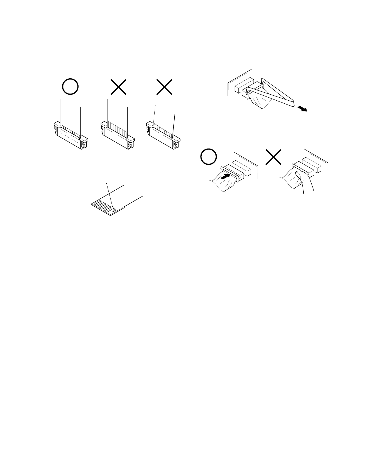
1. NOTE FOR REPAIR
Make sure that the flat cable and flexible board are not cracked of
bent at the terminal.
Do not insert the cable insufficiently nor crookedly.
When remove a connector, don’t pull at wire of connector.
It is possible that a wire is snapped.
Cut and remove the part of gilt
which comes off at the point.
(Be careful or some pieces of
gilt may be left inside)
When installing a connector, don’t press down at wire of connector.
It is possible that a wire is snapped.
SERVICE NOTE

– 6 –
SELF-DIAGNOSIS FUNCTION
1. Self-diagnosis Function
When problems occur while the unit is operating, the self-diagnosis function starts working, and displays on the monitor screen
what to do. This function consists of two display; self-diagnosis
display and service mode display.
Details of the self-diagnosis functions are provided in the Instruction manual.
Note: The “self-diagnosis display” data will be backed up by the coin-type lithium battery (HD-024 board BT701). When this
coin-type lithium battery is disconnected, the “self-diagnosis display” data will be lost by initialization.
2. Self-diagnosis Display
When problems occur while the unit is operating, the time code of
the monitor screen shows a 4-digit display consisting of an alphabet and numbers, which blinks at 3.2 Hz. This 5-character display
indicates the “repaired by:”, “block” in which the problem occurred, and “detailed code” of the problem.
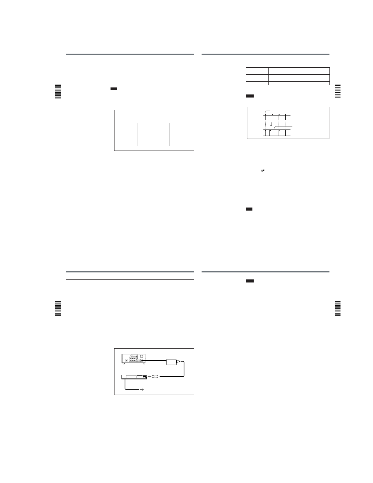
3. Service Mode Display
The service mode display shows up to six self-diagnosis codes shown in the past.
3-1. Display Method
With the unit set in STANDBY mode, while pressing the “STOP” button, press the “ON/STANDBY” button, and continue pressing the
“STOP” button for 5 seconds continuously. The service mode will be displayed, and the time code will show the backup No. and the 5-
character self-diagnosis codes.
3-2. Switching of Backup No.
By press the “F”, “f” button of supplied remote commander (RMT-DS11), past self-diagnosis codes will be shown in order. The backup
No. in the [] indicates the order in which the problem occurred. (If the number of problems which occurred is less than 6, only the number
of problems which occurred will be shown.)
[1] : Occurred first time [4] : Occurred fourth time
[2] : Occurred second time [5] : Occurred fifth time
[3] : Occurred third time [6] : Occurred the last time
3-3. End of Display
Turning OFF the power supply will end the service mode display.
Order of previous errors
Backup No.
Self-diagnosis Codes
C : 3 1 : 1 1
[3]
Lights up
monitor screen
[3] C : 3 1 : 1 1
1 1
3 1C
Repaired by:
Refer to page 7.
Self-diagnosis Code Table.
Indicates the appropriate
step to be taken.
E.g.
31 ....Reload the tape.
32 ....Turn on power again.
Block
Detailed Code
Blinks at 3.2Hz
C : Corrected by customer
H : Corrected by dealer
E : Corrected by service
engineer
monitor screen
C : 3 1 : 1 1
TC RESET
SERCH SELECT
DISPLAY
DATA CODE
MENU
SET
F, f button

– 7 –
4. Self-diagnosis Code Table
C
C
C
C
C
C
C
C
C
C
C
C
C
C
C
C
Block
Function
21
22
31
31
31
31
31
31
31
32
32
32
32
32
32
32
Detailed
Code
00
00
10
11
22
23
30
40
42
10
11
22
23
30
40
42
Symptom/State
Condensation.
Video head is dirty.
LOAD direction. Loading does not
complete within specified time
UNLOAD direction. Loading does not
complete within specified time
T reel fault.
S reel fault.
FG fault when starting capstan.
FG fault when starting drum.
FG fault during normal drum operations.
LOAD direction loading motor time-
out.
UNLOAD direction loading motor
time-out.
T reel fault.
S reel fault.
FG fault when starting capstan.
FG fault when starting drum.
FG fault during normal drum
operations.
Self-diagnosis Code
Repaired by:
Correction
Remove the cassette, and insert it again after one hour.
Clean with the optional cleaning cassette.
Load the tape again, and perform operations from the beginning.
Load the tape again, and perform operations from the beginning.
Load the tape again, and perform operations from the beginning.
Load the tape again, and perform operations from the beginning.
Load the tape again, and perform operations from the beginning.
Load the tape again, and perform operations from the beginning.
Load the tape again, and perform operations from the beginning.
Remove the power cable, connect, and perform operations from
the beginning.
Remove the power cable, connect, and perform operations from
the beginning.
Remove the power cable, connect, and perform operations from
the beginning.
Remove the power cable, connect, and perform operations from
the beginning.
Remove the power cable, connect, and perform operations from
the beginning.
Remove the power cable, connect, and perform operations from
the beginning.
Remove the power cable, connect, and perform operations from
the beginning.
1-1
SECTION 1
GENERAL
DSR-11
This section is extracted from DSR-11
instruction manual.
Features
Chapter
1 Overview
6
(GB) Chapter 1 Overview
Chapter
1
Overview
Features
The DSR-11 is a 1/4-inch digital video cassette recorder
that uses the DVCAM
TM
digital recording format. This
system achieves stable, superb picture quality by
digitally processing video signals that are separated
into color difference signals and luminance signals
(component video).
With a compact, lightweight and space-saving case,
the unit can be installed vertically and is equipped with
an analog interface as well as a digital interface
enabling connection to a digital device such as a
computer.
The DSR-11’s main features are described below.
DVCAM Format
DVCAM is based on the consumer DV format, which
uses the 4:1:1 component digital format (NTSC) or the
4:2:0 format (PAL), and provides a
1
/4-inch digital
recording format for professional use.
High picture quality, high stability
Video signals are separated into color difference
signals and luminance signals, which are encoded and
compressed to one-fifth size before being recorded to
ensure stable and superb picture quality.
Because the recording is digital, multi-generation
digital dubbing can be performed with virtually no
deterioration of quality.
Wide track pitch
The recording track pitch is 15 µm, fully 50 percent
wider than the DV format’s 10-µm track pitch. Thanks
to this feature, the DVCAM format sufficiently meets
the reliability and precision requirements of
professional editing.
High-quality PCM digital audio
PCM recording makes for a wide dynamic range and a
high signal-to-noise ratio, thereby enhancing sound
quality.
There are two recording modes: 2-channel mode (48kHz sampling and 16-bit linear code), which offers
sound quality equivalent to the DAT (Digital Audio
Tape) format, or 4-channel mode (32-kHz sampling
and 12-bit nonlinear code).
DV format compatibility
A DV cassette recorded on a DV-format VCR can be
played back on the unit (SP mode only). The unit can
also record in DV format (SP mode only). (Recording/
playing back an image in LP mode is not available.)
Chapter 1
Overview
Chapter 1 Overview7 (GB)
NTSC/PAL systems compatible
The unit is compatible with NTSC and PAL systems.
When inputting the signals to the DV IN/OUT
connector or playing back a tape, the color system of
signals is detected automatically. The color system
select switch on the unit allows input of analog video
signals in either color system. This compatibility
allows you to record (download) or play back (upload)
both NTSC and PAL formatted signals with your
VCR, computer, or other equipment.
However, the unit cannot convert the color system of
the signals.
Choice of two cassette sizes
The unit can use both standard-size and mini-size
DVCAM or DV cassettes.
•According to cassette size, the position of the reel
drive plate changes automatically.
•The maximum recording/playback times are 184
minutes for standard size cassettes and 40 minutes for
mini-size cassettes (DVCAM format).
Remote control
The unit can be operated by remote control from a
CONTROL-S system remote control unit, the DSRM20 (not supplied).
High-speed search function
When you use an editing controller or the optional
remote control unit (DSRM-20), the unit has a picture
search function that allows you to view color picture at
playback speeds up to 14 times (NTSC) or up to 17
times (PAL) normal speed in forward and reverse
directions. You can also search frame-by-frame in jog
mode.
You can also hear playback audio.
Digital slow playback
The unit has a frame memory function that allows
smooth, slow playback. This is available only at +
1
/3-
time speed and –
1
/3-time speed.
Jog audio function
If you use the optional remote control unit DSRM-20,
audio can be monitored at various playback speeds
when in jog mode.
Other Features
Compact and can be installed vertically
The unit is compact and can be installed vertically.
With non-linear editing system, you can save space by
installing it vertically beside your computer.
Menu system for functionality and
operation settings
The unit provides a menu system to make its various
functions easier to use and set up.
Superimposition function
Time code, operation mode indications, menus, error
messages, and other text data can be superimposed and
output in analog video signals.
Easy maintenance functions
• Self-diagnostics/alarm functions: The system
automatically detects an invalid operation, an invalid
connection or a malfunction, and outputs a
description, a cause and a recovery method as a
message superimposed on analog video signals.
• Digital hours meter: A digital hours meter counts
four types of time data—operating time, drum
rotation time, tape running time, and tape threading/
unthreading. The digital hours data is displayed in the
menu.
, , and
are trademarks of Sony
Corporation.
........................................................................................
Location and Function of Parts
Chapter
1 Overview
8
(GB) Chapter 1 Overview
Front Panel
Location and Function of Parts
1 Cassette lid
To insert/eject a cassette, open the lid.
For details of usable cassettes, see “Notes on Video
Cassettes” on page 15 (GB).
2 REMOTE CONTROL switch
Selects whether the unit is operated from the Remote
Commander or from an optional remote control unit.
WIRELESS: The unit is operated from the Remote
Commander.
CONTROL S: The unit is operated from a remote
control unit (the DSRM-20, not supplied),
connected to the CONTROL S jack on the rear
panel.
Note
You can operate this unit from its front panel
regardless of this switch setting.
3 INPUT SELECT selector
You can select DV, S VIDEO, or VIDEO to input the
signals.
DV: Signal input from the DV IN/OUT connector
S VIDEO: Signal input from the S VIDEO connector
on INPUT jacks
VIDEO: Signal input from the VIDEO jack on
INPUT jacks
Note
Do not change the selector setting during recording.
Otherwise, noise is output to the picture and sound and
that portion will not be recorded properly.
4 Remote sensor
5 ON/STANDBY switch
2 REMOTE CONTROL switch
5 ON/STANDBY
switch
2 Indicators
(see page 10 (GB))
4 Remote sensor
3 INPUT SELECT selector
1 Cassette lid
1 Tape transport
control section
(see page 9 (GB))
Chapter 1
Overview
Chapter 1 Overview9 (GB)
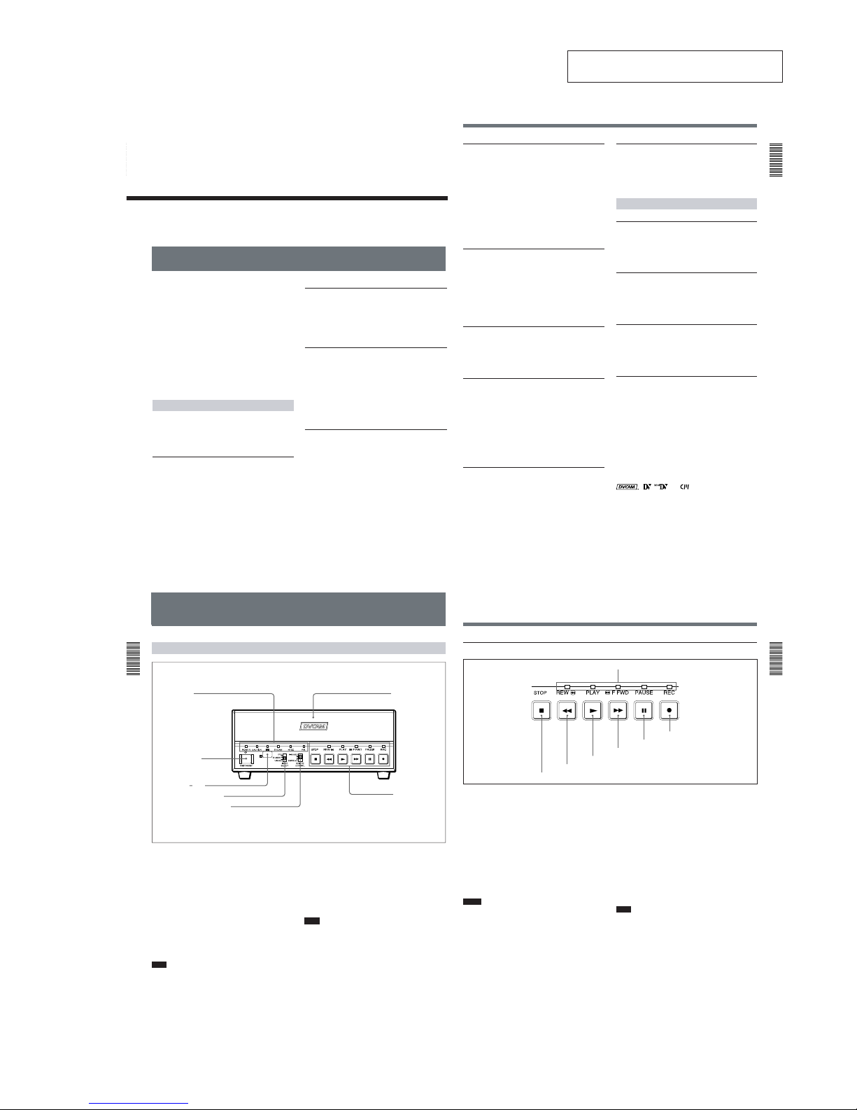
1 Tape transport control section
1 Tape transport indicators
2 REC (record) button
When you press the PLAY button while holding down
this button, the indicator lights and recording begins.
To set the unit to recording pause mode, press the
PAUSE and PLAY buttons while holding down this
button. If you press only this button when the unit is in
the stop mode and the DV IN TC on the OTHERS
menu is set to EXTERNAL, the REC indicator lights
and you can also check the EE signals for time code.
After checking them, press the STOP button.
For details on the OTHERS menu, see “OTHERS menu” on
page 49 (GB).
Notes
•The unit cannot record in the LP mode of the
consumer DV format. Only recording in the SP mode
is available.
•To set the unit to recording pause mode with the
remote control unit (DSRM-20, not supplied), press
the PAUSE button while holding down the PLAY
button to set the unit to the playback pause mode,
then press the REC button on the DSRM-20.
3 PAUSE button
Press this button to set the unit to pause mode while
recording or playing. Pressing this button again
resumes the operation. The indicator lights when the
unit is in pause mode.
4 F FWD (fast forward) button
When you press this button, the indicator lights and the
tape is fast forwarded. During fast forward, the picture
does not appear on the monitor (you can see the picture
as it is seen in the EE mode
1)
during fast forward).
To locate a scene while monitoring the picture, keep
pressing this button during fast forward, playback or in
playback pause mode (picture search).
You can change the tape transport mode in FF/REW
SPD on the VTR SET menu.
For details on the VTR SET menu, see “VTR SET menu” on
page 43 (GB).
Note
If you set the FF/REW SPD on the VTR SET menu to
SHUTTLEMAX, you can display the picture while
fast-forwarding the tape.
5 PLAY button
When you press this button, the indicator lights and
playback begins.
If you press this button while holding down the REW
button during stop, the tape is rewound to its beginning
and starts playing automatically (during rewind, the
REW indicator lights and the PLAY indicator flashes).
1) EE mode
“EE” stands for “Electric to Electric”. In this EE mode, the
video and audio signals that are input to the VCR’s
recording circuitry do not pass through any magnetic
........................................................................................................................................................................................................
conversion circuits but instead are output via electric circuits
only. This mode is used to check the input signals and adjust
input levels. The pictures output in EE mode are referred to
as EE pictures.
1 Tape transport indicators
2 REC button
3 PAUSE button
4 F FWD button
5 PLAY button
6 REW button
7
STOP button

1-2
Location and Function of Parts
Chapter
1 Overview
10
(GB) Chapter 1 Overview
Notes
•When the unit is playing back a part of the tape where
the recording format has been changed between the
DVCAM format and the DV format, the picture and
sound may be distorted.
•The unit cannot play back a tape recorded in the LP
mode of the consumer DV format.
6 REW (rewind) button
When you press this button, the indicator lights and the
tape starts rewinding. During rewind, the picture does
not appear on the monitor (you can see the picture as it
is seen in the EE mode during rewind).
To locate a scene while monitoring the picture, keep
pressing this button during rewind, playback or in
playback pause mode (picture search).
If you press the PLAY button while holding down this
button during stop, the tape is rewound to its beginning
and starts playing automatically (during rewind, the
REW indicator lights and the PLAY indicator flashes).
You can change the tape transport mode in FF/REW
SPD on the VTR SET menu.
For details on the VTR SET menu, see “VTR SET menu” on
page 43 (GB).
Note
If you set the FF/REW SPD on the VTR SET menu to
SHUTTLEMAX, you can display the picture while
rewinding the tape.
7 STOP button
Press this button to stop the current tape transport
operation.
2 Indicators
1 POWER indicator
Lights in green when the power of this unit is on and
lights in red when the unit is in the standby mode.
2 CAUTION indicator
Flashes when an error occurs.
For details on cautions, see “Alarm Messages” on page
51 (GB).
3 q (cassette) indicator
Lights when a digital video cassette is loaded. Even
if the unit is in the standby mode, the indicator lights
as long as the cassette is inside of the unit. While the
cassette is being ejected, the indicator flashes.
4 DVCAM indicator
Lights when the unit is playing back a tape recorded
in DVCAM format.
When the REC MODE on the VTR SET menu is set
to DVCAM, this indicator also lights during
recording or in the EE mode.
For details on the VTR SET menu, see “VTR SET menu” on
page 43 (GB).
5 NTSC indicator
Lights when:
•the unit is in the EE mode, analog video signals are
input and the NTSC/PAL select switch is set to
NTSC.
•the unit is in the EE mode and NTSC formatted
video signals are input from the DV IN/OUT
connector.
•a tape that has NTSC formatted video signals is
being played back.
6 PAL indicator
Lights when:
•the unit is in the EE mode, analog video signals are
input and the NTSC/PAL select switch is set to PAL.
•the unit is in the EE mode and PAL formatted video
signals are input from the DV IN/OUT connector.
•a tape that has PAL formatted video signals is being
played back.
1 POWER indicator
2 CAUTION indicator
3 q indicator
4 DVCAM indicator
5 NTSC indicator
6
PAL indicator
Chapter 1
Overview
Chapter 1 Overview11 (GB)
Rear Panel
1 LANC jack
Connects to other video devices that have a LANC
jack. You can operate the unit from other video
devices.
Notes
•You cannot operate the ejection of a cassette from a
device connected to the LANC jack.
•The LANC jack on the unit has only LANC-S
functions. The unit has no LANC-M functions.
2 DV IN/OUT connector (4-pin)
Used to input/output a digital signal that complies with
the i.LINK standard (Recommended cable: VMCIL4415(A),VMC-IL4615(A)). Use when an external
device which you want to connect to the unit has a DV
jack. If you connect the unit and the other device using
DV jacks, you can minimize deterioration of picture
quality during recording, dubbing or capturing still
pictures into a personal computer by digital
processing. For details, refer to the instruction manual
of the equipment you use.
Note
i.LINK and the i.LINK logo “ ” are trademarks and
indicate that this product is in agreement with IEEE
1394-1995 specifications and their revisions.
3 INPUT jacks
Used to input analog video and audio signals. To
connect a VCR equipped with S-video output, use the
S VIDEO connector on the unit.
4 DC IN 12V connector
Connects to an AC power outlet using the supplied AC
power adaptor and power cord.
5 AUTO REPEAT switch
Used to repeat the playback of all or a part of the tape.
For details on the auto repeat function, see “Auto Repeat”
on page 32 (GB).
1 LANC jack
2 DV IN/OUT
connector
3 INPUT jacks
4 DC IN 12V
connector
5 AUTO REPEAT
switch
6 OUTPUT jacks
7 NTSC/PAL
select switch
8 RESET button
9
CONTROL S
jack
Location and Function of Parts
Chapter
1 Overview
12
(GB) Chapter 1 Overview
6 OUTPUT jacks
Used to output analog video and audio signals. To
connect a VCR equipped with S-video input, use the S
VIDEO connector on the unit.
Notes
•Various text data are superimposed and output from
the VIDEO jack or the S VIDEO connector on the
OUTPUT jacks. If you want to output video signals
without text data, carry out the following operations.
– Set TITLE DISP and LABEL DISP on the CM SET
menu to OFF.
– Depending on the displayed items, press the
MENU, DATA CODE, DISPLAY or SEARCH
SELECT button on the Remote Commander to
clear the text data on the monitor screen.
For details on text data, see “Displaying data recorded on a
tape” on page 25 (GB) and “Displaying various data” on
page 26 (GB).
For details on the CM SET menu, see “CM SET menu” on
page 46 (GB).
•When the unit is in the EE mode (when the input
signal is output as an analog signal), the subcarrier of
the color signal is not synchronized with the
horizontal sync signal. The color of the picture or the
horizontal sync signal may be distorted depending on
the type of monitor connected to the unit.
7 NTSC/PAL select switch
Used to switch the color system of signals that will be
recorded on the unit when you use analog input.
To change the switch setting, turn off the power of the
unit first, then use the tip of a ball-point pen or similar
tool to slide this switch.
Before inputting NTSC or PAL formatted analog video
signals, set this switch to appropriate position
according to the color system of it.
Notes
•If the color system of the input signals is different
from that of the switch setting, both picture and sound
will be muted.
•When inputting signals to the DV IN/OUT connector
or during playback, this switch setting is invalid. The
unit detects the color system of the signals
automatically.
•When the switch is set to PAL, the unit works as a
PAL model. Therefore the time code generated by the
unit while recording in the DVCAM format turns to
the non-drop frame mode. Even if an NTSC
formatted signal is input from the DV IN/OUT
connector, the time code generated by the unit is nondrop frame mode as long as the switch is set to PAL,
regardless of the TC FORMAT setting on the
OTHERS menu. If you intend to set the unit to
generate the time code in the drop frame mode, set
the switch to NTSC.
•The color system of the signals output from the unit
is the one recorded on the tape being played back.
The unit cannot convert the color system of signals of
one system into that of the other. (For example:
converting NTSC formatted signals into PAL
formatted signals is not possible) Therefore, to view
or record the signal output from the unit, you need a
device compatible with the color system of the
signals output from the unit.
•When the color system of playback signals is
different from the one last used on the unit, playback
picture and sound will be distorted and time code will
be discontinuous for a short time at the beginning of
the playback.
•If you play back a tape with both NTSC and PAL
color system recordings, the following limitations
apply.
– At the point where the recorded signals format
changes, the picture may be distorted or the audio
noise may be output.
– The tape transport control buttons may be disabled
until the tape running is stabilized.
•Do not change the switch setting during recording.
8 RESET button
Press this button to initialize the internal clock and all
menu items. Press this button with the tip of a ballpoint pen or similar tool.
9 CONTROL S jack
Connects to a remote control unit (DSRM-20, not
supplied) for controlling this unit.
Note
When using a CONTROL S-device, set the REMOTE
CONTROL switch on the front panel to CONTROL S.
Otherwise, you cannot operate the unit with
CONTROL S-devices.
Chapter 1
Overview
Chapter 1 Overview13 (GB)
1 TC RESET button
Press this button to reset the time code to 00:00:00:00
during recording or in the recording pause mode.
Note
When the command mode of a Sony device / remote
commander is set to VTR 4;
•if you press this button while pointing the Remote
Commander toward a Sony device other than this
unit, the HMS counter on that machine will be reset
to zero.
•if you press a counter reset button on a Sony remote
commander while pointing it toward this unit during
recording or in the recording pause mode, the time
code will be reset to zero.
Supplied Remote Commander
2 SEARCH SELECT buttons
Press these buttons to search for scenes using the
search function.
For details on the search function, see “Searching using the
search function” on page 29 (GB).
3 Buttons for playing at various speeds
You can play back a tape at normal speed or at a speed
other than normal with these buttons.
For details, see “Playing at various speeds” on page 28
(GB).
4 PAUSE button
5 PLAY button
PAUSE RE C
FRAME
x1/10 x1/3 x1 x2
SET
MENU
SEARCH SELECT
DATA CODE
DISPLAY
REW
PLAY
FF
STOP
TC RESET
5 PLAY button
6 REW button
7 On/standby switch
8 DISPLAY button
9 DATA CODE button
0 Buttons for menu operation
qa REC buttons
qs FF button
qd STOP button
2 SEARCH SELECT
buttons
3 Buttons for
playing at various
speeds
4 PAUSE button
1
TC RESET button
1-3
Location and Function of Parts
Chapter
1 Overview
14
(GB) Chapter 1 Overview
6 REW button
7 On/standby switch
8 DISPLAY button
Press this button to see indications, such as time code
and tape remaining time, on the monitor screen.
For details on displayed data, see “Displaying various
data” on page 26 (GB).
9 DATA CODE button
Press this button to see the data codes (recording date/
time, camera data) on the monitor screen.
For details on data codes, see “Displaying data recorded
on a tape” on page 25 (GB).
0 Buttons for menu operation
Press these buttons to operate the menu.
qa REC buttons
When you press these buttons at the same time, the
REC and PLAY indicators light and recording begins.
qs FF button
qd STOP button
Note
When using the Remote Commander, set the
REMOTE CONTROL switch on the front panel to
WIRELESS. Otherwise, you cannot operate this unit
with the Remote Commander.
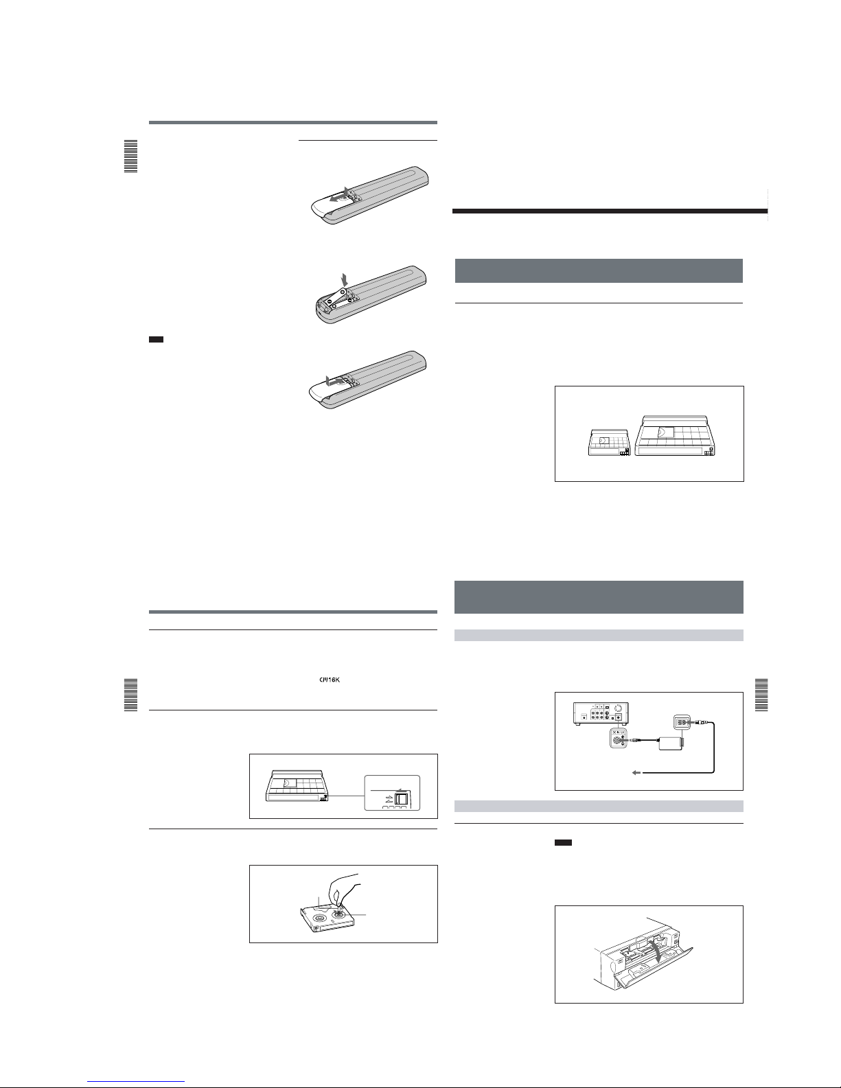
Battery installation
1
Push and slide the lid to open.
2
Install the two size AA (R6) batteries (supplied)
with the correct polarity.
3
Replace the lid.
Notes on batteries
•Make sure that the battery orientation is correct when
inserting batteries.
•Do not mix an old battery with a new one, or mix
different types of batteries.
•If you will not use the Remote Commander for a long
time, remove the batteries to avoid damage from
battery leakage. If batteries have leaked, remove
them, wipe the battery compartment dry and replace
the batteries with new ones.
Be sure to install the
battery from the #
side.
Chapter 2
Playback
and Recording
Chapter 2 Playback and Recording15 (GB)
Chapter
2
Playback and
Recording
Notes on Video Cassettes
Usable cassettes
Use Standard-DVCAM cassettes or Mini-DVCAM cassettes with this unit.
The PDV-184 can record programs for 184 minutes (DVCAM format) /
270 minutes (DV format) and the PDVM-40 can record for 40 minutes
(DVCAM format) / 60 minutes (DV format).
You can get the highest quality pictures with this digital videocassette
recorder using DVCAM cassettes. You may not be able to get as good
quality with other cassettes. We recommend using DVCAM cassettes so
that you can record your one-time events in the highest quality.
DVCAM cassette
Mini DVCAM cassette
Notes on Video Cassettes
Chapter
2 Playback
and Recording
16
(GB) Chapter 2 Playback and Recording
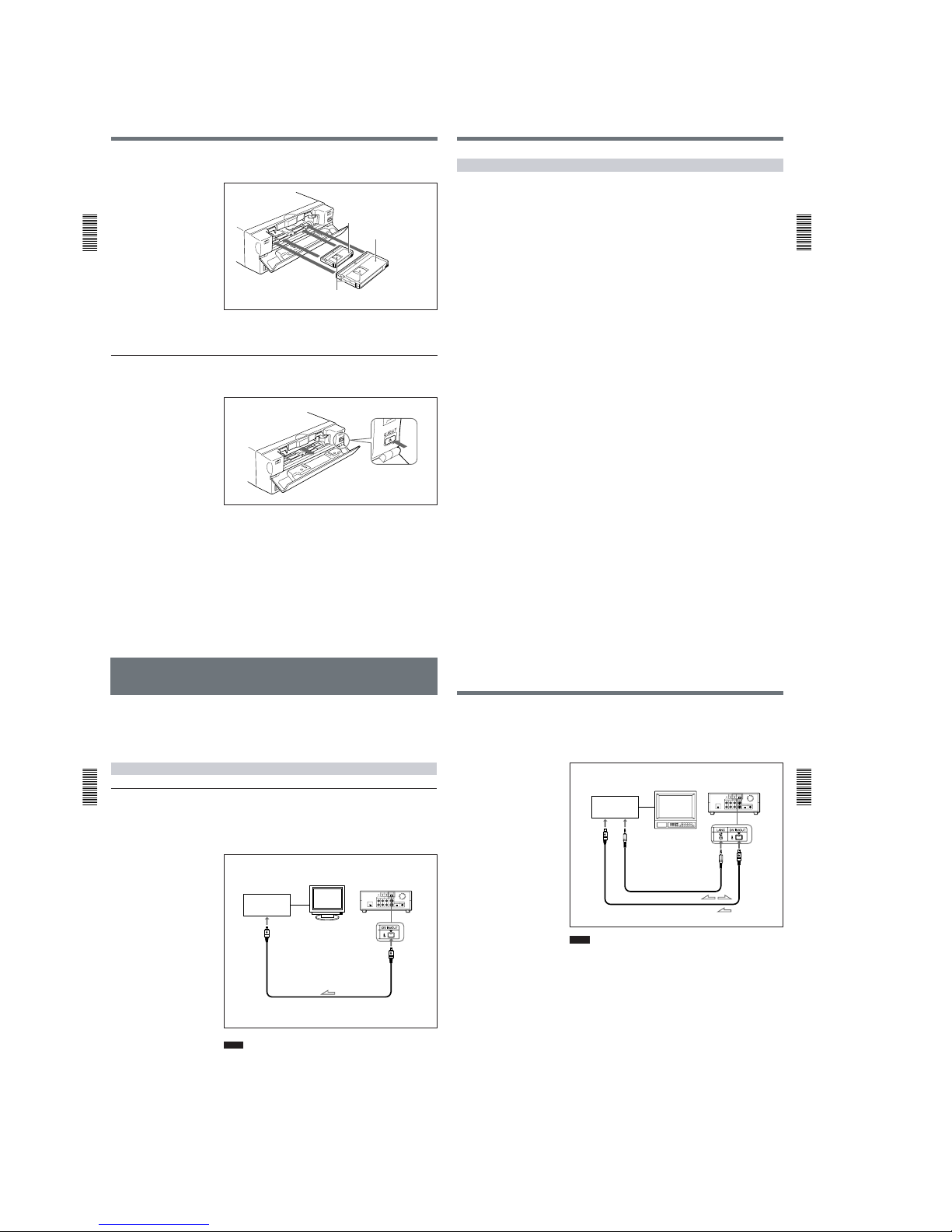
Cassette memory
Cassette memory is an optional feature that is mounted on some Standard
DVCAM/DV cassettes and Mini DVCAM/Mini DV cassettes. When you
record a program, the recording date and time, and the programs’ position
on the tape are stored in the cassette memory so that you can quickly
locate the program later on.
indicates that you can use the
cassettes to store up to 16 kbits of data. On this unit, you can use cassettes
on which up to 16 kbits of data can be stored.
To save a recording
To prevent accidental erasure of a recording, slide the REC/SAVE switch
on the cassette so that the red portion becomes visible. To record on a tape,
slide the switch so that the red portion is hidden.
Checking the tape for slack
Using a paper clip or a similar object, turn the reel gently in the direction
shown by the arrow. If the reel does not move, there is no slack.
REC/SAVE switch
REC
SAVE
Set to SAVE.
Paper clip, etc.
Reel
Chapter 2
Playback
and Recording
Chapter 2 Playback and Recording17 (GB)
Power Preparations
Connect the power cord (supplied) to the AC adaptor (AC-SU1, supplied)
and connect the AC adaptor to the DC IN 12V connector on the unit. Then,
connect the power plug to the wall outlet.
When you undo these connections, be sure to disconnect the power cord
from the wall outlet first.
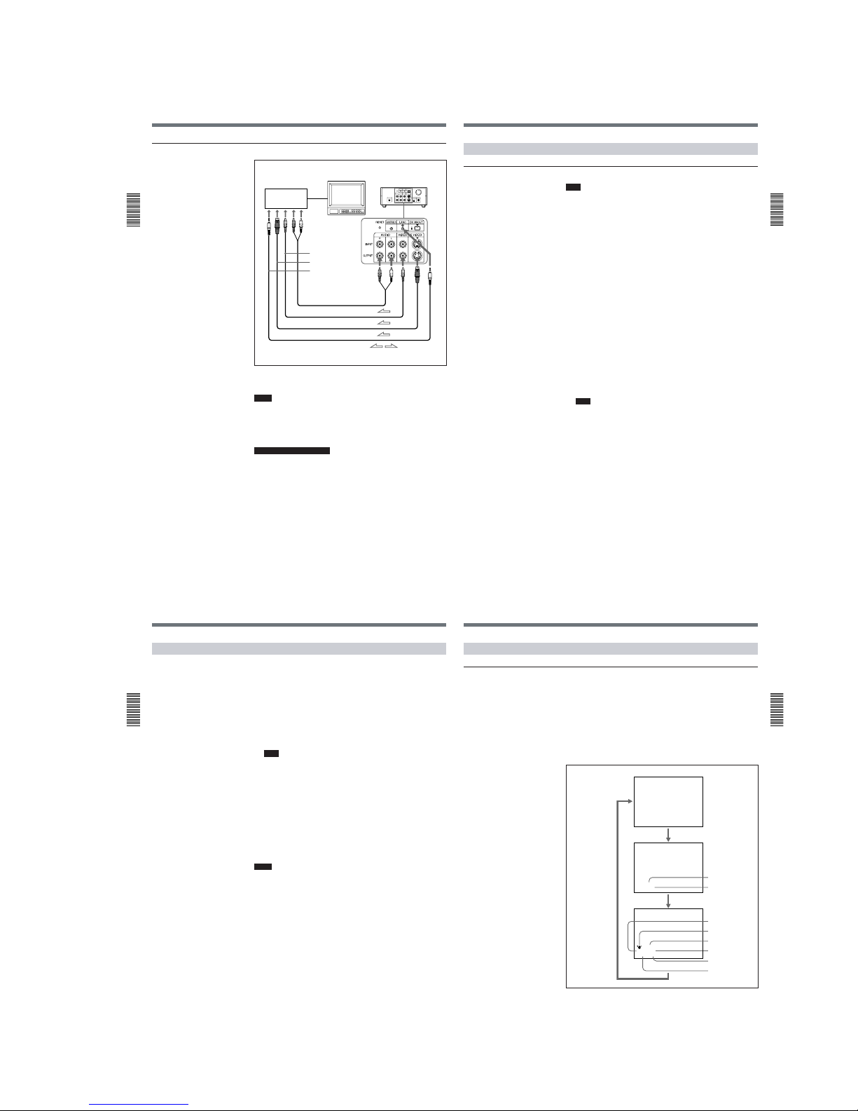
Inserting/Ejecting Cassettes
To insert a cassette
Notes
•Do not insert the cassette forcibly. The unit may be damaged.
•Do not eject/load the cassette in a place subject to light. Make sure to
close the cassette lid when using the unit. The internal sensor of the unit
may operate incorrectly if too much light finds its way into the unit.
1
With the unit powered on, confirm that the q indicator is off, then
open the cassette lid.
Preparations
(Continued)
DSR-11
to wall outlet
AC adaptor
AC-SU1 (supplied)
to DC IN 12V
connector
P
ower cord (supplied)
1-4
Preparations
Chapter
2 Playback
and Recording
18
(GB) Chapter 2 Playback and Recording
2
After checking the tape for slack, hold the cassette so that the tape
window is facing upward, then insert it into the unit.
The cassette is automatically loaded into the unit.
3
Close the cassette lid.
To eject the cassette
1
With the unit powered on, open the cassette lid. Press the EJECT
button located at the right side of the cassette compartment.
The cassette is unloaded and ejected.
2
Remove the cassette from the unit. Close the cassette lid.
Mini cassette
Insert the mini cassette into the
center of the cassette compartment.
Standard cassette
Tape window facing upward
Chapter 2
Playback
and Recording
Chapter 2 Playback and Recording19 (GB)
Notes on Recording/Playback
No compensation for contents of the recording
Contents of the recording cannot be compensated for if recording or
playback is not successful due to a malfunction of the unit, video tape, etc.
Copyright precautions
On recording
You cannot record any software having copyright protection signals on
this unit. If you start recording protected video and audio signals, a
warning appears on the monitor screen and the unit stops recording.
On playback
If you play back a software having copyright protection signals on this
unit, you may not be able to copy it onto other equipment.
Limitations caused by the difference in format
The unit can record and play back tapes recorded in DVCAM format. It
can also record and play back tapes recorded in DV format (SP mode).
However, due to the difference in format, you may not be able to record or
edit some tapes affected by recording conditions of the tape.
For details, see “Compatibility of DVCAM and DV Format ” on page 55 (GB).
Playback
Chapter
2 Playback
and Recording
20
(GB) Chapter 2 Playback and Recording
Playback
This section describes the necessary connections, settings, and operations
to perform playback on this unit. The same settings and operations apply
whether you are using the unit for dubbing or as a stand-alone
videocassette player.
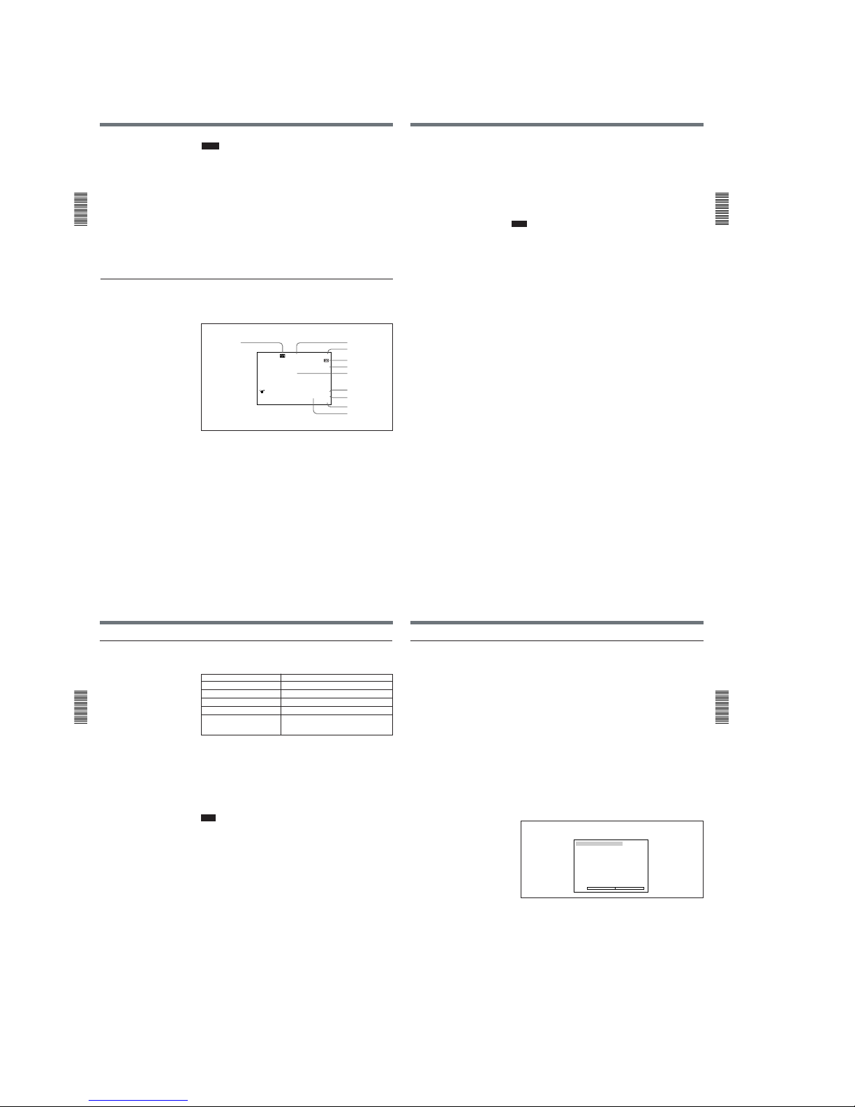
Connections for Playback
To equipment with a DV jack
Connecting to a computer
The video and audio signals are sent to a computer with virtually no
deterioration in quality, enabling high-quality uploading. The signal flow
is automatically detected so you do not need to make separate connections
for input and output.
Notes
•Set DV EE OUT on the VTR SET menu to OFF.
For details on the VTR SET menu, see “VTR SET menu” on page 43 (GB).
•With the DV connection, data codes (recording date/time, camera data)
recorded on the source tape are transmitted from this unit (player).
Recorder
Player
Computer
Monitor
DSR-11
to the
DV jack
i.LINK cable (DV cable) (not supplied)
l
: Signal flow
Chapter 2
Playback
and Recording
Chapter 2 Playback and Recording21 (GB)
Connecting to another VCR
The video and audio signals are sent to another VCR with virtually no
deterioration in quality, enabling high-quality recording. The signal flow is
automatically detected so you do not need to make separate connections
for input and output.
Notes
•Set DV EE OUT on the VTR SET menu to OFF.
For details on the VTR SET menu, see “VTR SET menu” on page 43 (GB).
•With the DV connection, the sound is recorded in the same audio
recording mode as that of the source tape. To record in a different audio
recording mode from the source tape, use the analog connection instead.
•With the DV connection, data codes (recording date/time, camera data)
recorded on the source tape are transmitted from this unit (player). As a
result, when you play back a recorded tape on this unit and press the
DATA CODE button on the Remote Commander, the same data codes
recorded on the source tape are displayed on the monitor screen.
•As for the LANC connection, see “Notes for a LANC connection” on the
next page.
Recorder
Player
Other VCR
Monitor
DSR-11
to the
DV jack
to the
LANC jack
LANC cable (not supplied)
i.LINK cable (DV cable) (not supplied)
l
: Signal flow
1-5
Playback
Chapter
2 Playback
and Recording
22
(GB) Chapter 2 Playback and Recording
To video equipment without a DV jack
Connect either an S-video cable or a video cable as the cable for video
signals.
Notes
•When you connect the output jacks of the recorder to the input jacks of
this unit, select the input correctly with an input select switch on the
recorder to prevent a humming noise or distortion of the picture.
•Distorted signals (e.g., when played back at a speed other than normal)
will not be recorded properly.
Notes for a LANC connection
•The LANC connection transmits signals such as control signals, time
code, time counter data, and status data.
•Jacks labeled CONTROL L have the same function as LANC jacks.
Jacks labeled REMOTE may also have the same function.
•Set the LANC switch on the recorder to M. A device which does not have
M / S switch cannot be used to control this unit.
Recorder
Player
Other VCR
Monitor
DSR-11
to the S-video
input connector
to the video input jack
to the audio input
jacks
to the LANC jack
Audio cable (not supplied)
Video cable (not supplied)
S-video cable (not supplied)
LANC cable (not supplied)
l
: Signal flow
Chapter 2
Playback
and Recording
Chapter 2 Playback and Recording23 (GB)
Settings for Playback
Preparation on the player (this unit)
Note
Various text data are superimposed and output from the VIDEO jack or
the S VIDEO connector on the OUTPUT jacks. If you want to record
video signals without text data, carry out the following operations.
•Set TITLE DISP and LABEL DISP on the CM SET menu to OFF.
•Depending on the displayed items, press the MENU, DATA CODE,
DISPLAY or SEARCH SELECT button on the Remote Commander to
clear the text data on the monitor screen.
For details on text data, see “Displaying data recorded on a tape” on page 25
(GB) and “Displaying various data” on page 26 (GB).
For details on the CM SET menu, see “CM SET menu” on page 46 (GB).
1
Power on the video monitor, then set the monitor’s input switch
according to the signals input from the recorder.
2
Set up the recorder.
For details, refer to the instruction manual of the recorder.
3
Power on this unit by pressing the ON/STANDBY switch on this unit.
4
When you play back a tape recorded in 4-channel mode (Fs32k),
adjust the balance between channel 1/2 and channel 3/4 with AUDIO
MIX on the AUDIO SET menu.
For details on the AUDIO SET menu, see “AUDIO SET menu” on page 44
(GB).
Note
The AUDIO MIX on the AUDIO SET menu (audio balance
adjustment) does not function on the source audio output through the
DV IN/OUT connector.
Playback
Chapter
2 Playback
and Recording
24
(GB) Chapter 2 Playback and Recording
Playback Procedure
This section describes the procedures used to play back a tape and send
signals to another VCR. For details on the procedures required when using
a computer as a recorder, refer to the instruction manual of your computer
or the user’s manuals of the software installed in it.
1
After checking the tape for slack and confirming that the q indicator
is off, hold the cassette so that the tape window is facing upward, then
insert it into this unit.
For details on checking the tape for slack, see “Notes on Video Cassettes” on
page 15 (GB).
Note
Do not insert the cassette forcibly. The unit may be damaged.
The cassette is automatically loaded into the unit.
2
Press the PLAY button.
This unit starts playback.
To stop playback
Press the STOP button on the unit.
To pause playback
Press the PAUSE button on the unit.
Notes
•When this unit is playing back a part of the tape where the recording
format has been changed between the DVCAM format and the DV
format, the picture and sound may be distorted.
•This unit cannot play back a tape recorded in the LP mode of the
consumer DV format.
Chapter 2
Playback
and Recording
Chapter 2 Playback and Recording25 (GB)
Playback Functions
Displaying data recorded on a tape
If you record on a tape using a Sony digital camcorder (DSR-200/200P,
200A/200AP, PD100/PD100P, PD100A/PD100AP, PD150/PD150P, 250/
250P, etc.), data codes (the shutter speed, SteadyShot, program AE mode,
white balance, iris, gain, date and time) can be recorded on the tape. You
can check these data items during playback on this unit.
Press the DATA CODE button on the Remote Commander during
playback.
Each time you press the DATA CODE button, the display changes as
follows.
2000 12 25
19 : 20 : 30
MANUAL
10000 ATW
F 1.6 0 dB
Shutter speed
SteadyShot
Program AE
White balance
Gain
Iris
No indicator
Recording
date/time
Camera data
Date
Time
(Continued)
1-6
Playback
Chapter
2 Playback
and Recording
26
(GB) Chapter 2 Playback and Recording
Notes
•The data codes are also displayed by setting DATA CODE on the
DISPLAY SET menu. You can change the displayed item in the same
way as described above.
Example
Menu setting : CAMERA
Display :
camera data t no indicator t recording date/time t camera data
For details on the DISPLAY SET menu, see “DISPLAY SET menu” on page 45
(GB).
•Camera data items show the settings of a tape recorded by a digital
camcorder (DSR-200/200P, 200A/200AP, PD100/PD100P, PD100A/
PD100AP, PD150/PD150P, 250/250P, etc.). This unit cannot record
camera data.
•When the data codes were not recorded, “- - -” appears instead.
•Some of the camera data items displayed on the monitor screen by this
unit are different from those shown by the digital camcorder.
Displaying various data
You can check various data items such as the time code, tape remaining
time, etc. on the monitor screen. These data items are useful for normal
recording/playback operation.
An item with * is displayed when you press the DISPLAY button on the Remote
Commander.
You can hide the item by pressing the DISPLAY button again.
1 Cassette memory indicator*
This is shown when a cassette with cassette memory has been loaded.
2 Tape transport mode indicator*
Displays the tape transport mode.
MANUAL
10000 ATW
F1. 6 12
dB
N
00:12:34:12
122min
PHOTO –10
SEARCH
DVCAM
NS 48K
DV I
N
%
1
2
3
4
5, 6
7
8
9
0
qa
Chapter 2
Playback
and Recording
Chapter 2 Playback and Recording27 (GB)
3 Time code indicator*
•Displays the time code. In the drop frame mode (only for NTSC), a
period is displayed between the minute and second. (Example:
00:12.58:00)
•Displays the diagnostics code numbers if the self-diagnostic function is
enabled.
4 Tape remaining time indicator*
If qREMAIN on the DISPLAY SET menu has been set to ON, the
remaining tape time is displayed.
Note
If the tape has been rewound to the beginning, this indicator will not show
the tape time remaining when the tape is inserted into the unit. The
remaining tape time is displayed after the tape runs for a while.
5 Search indicator
Displays the search mode when you search for scenes with the Remote
Commander or the DSRM-20 (not supplied).
For details on the search function, see “Searching using the search function” on
page 29 (GB).
6 Index indicator*
Displays the INDEX MARK when an index has been marked.
7 Caution indicators*
Displays a caution.
For details on cautions, see “Alarm Messages” on page 51 (GB).
8 DVCAM/DV indicator*
In the EE and recording modes, displays the recording format selected in
REC MODE on the VTR SET menu. During playback, displays the
recording format recorded on the tape.
9 Audio mode indicator*
In the EE and recording modes, displays the audio mode selected in
AUDIO MODE on the AUDIO SET menu. During playback, displays the
audio mode recorded on the tape. When inputting signals from the DV IN/
OUT connector, displays the audio mode of signals input from the DV IN/
OUT connector.
0 Input signal indicator*
Displays the INPUT SELECT selector setting.
qa NS (Non Standard) audio mode indicator*
This is shown when you play back a tape in the unlock audio mode or
when the unlock mode signal has been input from the DV IN/OUT
connector. Always this is shown when the REC MODE on the VTR SET
menu has been set to DV SP and the unit is in the EE mode.
For details on the unlock mode, see “Compatibility of DVCAM and DV Format”
on page 55 (GB).
Playback
Chapter
2 Playback
and Recording
28
(GB) Chapter 2 Playback and Recording
Playing at various speeds
You can enjoy playback functions using the Remote Commander.
Playback options Operation
Play at 1/10 of normal speed Press × 1/10 during playback.
Play at 1/3 of normal speed Press × 1/3 during playback.
Play at normal speed Press × 1 during playback.
Play at twice the normal speed Press × 2 during playback.
Play frame by frame Press FRAME c/C during pause.
If you keep pressing one of these buttons,
playback continues, frame by frame.
To change playback direction
Press the FRAME c/C buttons during playback at various speeds.
To play back in the forward direction, press the C button; in the
backward direction, press the c button.
To hear the sound when playing at various speeds
If you want to hear the sound when playing at various speeds, set JOG
AUDIO on the AUDIO SET menu to ON.
For details on the AUDIO SET menu, see “AUDIO SET menu” on page 44 (GB).
Note
When the command mode of a Sony device / remote commander is set to
VTR 4;
•if you press the ×1/3 button while pointing the Remote Commander
toward a Sony device other than this unit, the playback speed may turn to
1/5 of normal speed.
•if you press the ×1/5 button on a remote commander while pointing it
toward this unit,
the playback speed will turn to 1/3 of normal speed.
Chapter 2
Playback
and Recording
Chapter 2 Playback and Recording29 (GB)
Searching using the search function
There are four kinds of search available on this unit:
– Searching for the beginnings of recordings: Index search
– Searching for the boundaries of recorded tape by title: Title search*
– Searching for a point on the tape where the recorded date changes: Date
search
– Searching for scenes recorded in the photo mode with a digital
camcorder: Photo search
*:A function available only on a cassette with cassette memory
Searching with the cassette memory
If you set the CM SEARCH on the CM SET menu to ON and the tape has
cassette memory, the recordings are listed in the chronological order in
which they were made. You can search using this chronological list.
If the tape does not have cassette memory, you cannot search for scenes in
chronological order.
For details on the CM SET menu, see “CM SET menu” on page 46 (GB).
1
Press the SEARCH SELECT button on the Remote Commander to
select the search type: INDEX, TITLE, DATE or PHOTO SEARCH.
A chronological list appears on the monitor screen.
The date and time display can be changed by setting DATE DISP and TIME
DISP on the DISPLAY SET menu.
For PAL model, “PROG” is displayed instead of “CH.”
For details on the DISPLAY SET menu, see “DISPLAY SET menu” on page
45 (GB).
2
Press the . or > button to select a recording.
The unit starts searching and when it locates the recording, begins
playback. During Photo search, the unit turns to the playback pause
mode.
INDEX SEARCH
CH
1 0 0 / 2 / 2 8 1 : 0 0 LINE
2 0 0 / 3 / 7 1 2 : 5 9 LINE
3 0 0 / 3 / 1 1 3 : 0 5 LINE
4 0 0 / 5 / 5 1 9 : 0 0 LINE
5 0 0 / 7 / 3 1 0 : 1 5 LINE
6 0 0 / 1 0 / 2 8 1 2 : 2 0 LINE
v
q
When selecting INDEX SEARCH
1-7
Playback
Chapter
2 Playback
and Recording
30
(GB) Chapter 2 Playback and Recording
Searching without cassette memory
When you use a tape without cassette memory, the unit searches in the
order of the actual positions of the recordings, regardless of the setting of
CM SEARCH on the CM SET menu.
When you use a tape with cassette memory, set CM SEARCH on the CM
SET menu to OFF.
For details on the CM SET menu, see “CM SET menu” on page 46 (GB).
Note
The title search is not available in searching without cassette memory.
1
Press the SEARCH SELECT button on the Remote Commander to
select the search type.
2
Press the . or > button repeatedly to locate the recording you
want.
Each time you press the . or > button, the unit searches for the
previous or next search point. When an search point is located, its
number is indicated on the monitor screen.
The unit starts searching backwards or forwards until the number
comes to zero, then plays back the recording. During Photo search, the
unit turns to the playback pause mode.
How signals are recorded
There are four different signal types, one for each search method; index,
title, date and photo signals. They are recorded by the digital camcorder
(DSR-200/200P, 200A/200AP, PD100/PD100P, PD100A/PD100AP,
PD150/PD150P, 250/250P, etc.). However, the type of signal recorded and
where it is recorded (on the tape or in the cassette memory) depends on
whether the cassette has cassette memory or which type of video
equipment is used for recording. Please note that if the signals for a certain
search type are not recorded, you cannot do that type of search. For details
on the signals used for a particular type of search, refer to the instruction
manual of the recorder.
INDEX 00
SEARCH
When selecting INDEX SEARCH
Chapter 2
Playback
and Recording
Chapter 2 Playback and Recording31 (GB)
When you record on this unit
Signals for In cassette memory On tape
Index search* Yes Yes
Title search No No
Date search No Yes
Photo search No No
* The signals for Index search are recorded when you start recording in stop mode.
Notes
•If you record another program over the beginning of the search signals,
you will not be able to locate the original program.
•You cannot add search signals after recording.
To add signals only for Auto Repeat, start recording from the point you
want to add them.
•When recording on this unit, signals for index search do not have
information on the day of the week.
•Searching may not be done correctly if the signals were not recorded on a
piece of Sony-brand digital video equipment.
About the cassette memory
•A tape with
mark has cassette memory. When using the 16 kbits
cassette memory, you can store up to 135 search signals. (The number
changes depending on the memory capacity of various tapes. It also
changes depending on the data size combination of index, title, date,
photo, and tape label data stored on a tape.) This unit is capable of storing
and retrieving up to 16 kbits of information in cassette memory.
•To locate recordings that did not fit in the cassette memory, or to locate
recordings in order of their position on the tape, set CM SEARCH on the
CM SET menu to OFF. You can use the same procedure to search for a
recording on a tape without cassette memory.
For details on the CM SET menu, see “CM SET menu” on page 46 (GB).
Note
The number of search signals that you can record is limited by the cassette
memory space available when you start recording. When you use a
previously recorded tape for repeated recordings, make more memory
space available by erasing unwanted items using ITEM ERASE or ERASE
ALL on the CM SET menu before you start recording.
Search signal
B cannot be
searched for
If D is recorded
over the beginning of B...
ABC
CADB
Playback
Chapter
2 Playback
and Recording
32
(GB) Chapter 2 Playback and Recording
Auto Repeat
This unit can repeat the playback of all or a part of the tape.
1
Set the AUTO REPEAT switch on the rear panel to ON.
2
Press the REW button. (If the tape is already rewound, press the PLAY
button.)
The unit rewinds the tape to its beginning, and starts playback
automatically. The unit repeats the playback from the beginning to the
first index (if there is no signal for index search on the tape, to the next
unrecorded portion; if there is no unrecorded portion, to the end of the
tape).
Auto Repeat using an external AC timer
If you connect an external AC timer (not supplied) to this unit, you can
repeat playback automatically at the preset time.
1
Connect an external AC timer (not supplied) to this unit.
2
Set the AUTO REPEAT switch on the rear panel to ON.
3
Set the starting time on the external AC timer.
At the preset time, the power of this unit turns on, and after a few
seconds (no more than 30), Auto Repeat playback starts automatically.
The unit repeats the playback from the beginning to the first index (if
there is no signal for index search on the tape, to the next unrecorded
portion; if there is no unrecorded portion, to the end of the tape).
DSR-11
AC adaptor
AC timer
to a wall outlet
Chapter 2
Playback
and Recording
Chapter 2 Playback and Recording33 (GB)
Notes
•The unit cannot search for a signal for index search or an unrecorded
portion within 20 seconds of the beginning of the playback.
•While a tape is running, be sure not to turn off the power by using an AC
timer. The unit and the tape may be damaged. When turning off the
power of the unit, make sure to press the STOP button on this unit first to
stop the tape transport, then turn off the power.
To stop Auto Repeat
Press the STOP button on this unit.
To release the Auto Repeat mode
Set the AUTO REPEAT switch on the rear panel to OFF.
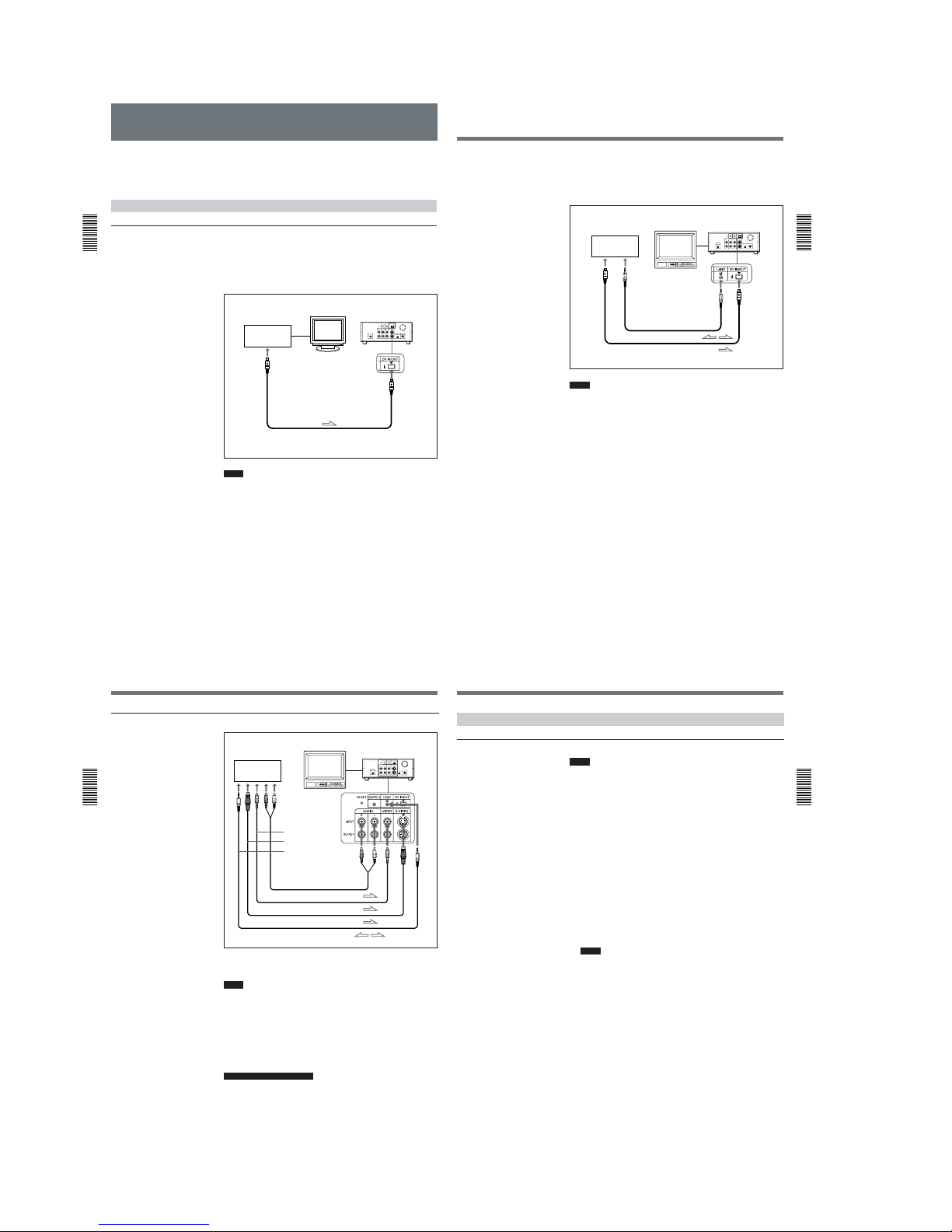
1-8
Recording
Chapter
2 Playback
and Recording
34
(GB) Chapter 2 Playback and Recording
Recording
This section describes the necessary connections, settings and operations
to perform recording on this unit. The same settings and operations apply
whether you are using the unit for dubbing or as a stand-alone recorder.
Connections for Recording
To equipment with a DV jack
Connecting to a computer
The video and audio signals are sent from a computer with virtually no
deterioration in quality, enabling high-quality downloading. The signal
flow is automatically detected so you do not need to make separate
connections for input and output.
Notes
•With the DV connection, data codes (recording date/time, camera data)
are transmitted from the computer (player). However, the contents of the
cassette memory are not transmitted.
•If no picture appears via the DV jack, disconnect, then reconnect the
i.LINK cable (DV cable).
Player
Recorder
Computer
Monitor
DSR-11
to the
DV jack
i.LINK cable (DV cable) (not supplied)
l
: Signal flow
Chapter 2
Playback
and Recording
Chapter 2 Playback and Recording35 (GB)
Connecting to another VCR
The video and audio signals are sent from another VCR with virtually no
deterioration in quality, enabling high-quality recording. The signal flow is
automatically detected so you do not need to make separate connections for
input and output.
Notes
•With the DV connection, the sound is recorded in the same audio
recording mode as that of the source tape. To record in a different audio
recording mode from the source tape, use the analog connection instead.
•With the DV connection, data codes (recording date/time, camera data)
recorded on the source tape are transmitted from the other VCR (player).
As a result, when you play back a recorded tape on this unit and press the
DATA CODE button on the Remote Commander, the same data codes
recorded on the source tape are displayed on the monitor screen.
However, the contents of the cassette memory are not transmitted.
•If no picture appears via the DV jack, disconnect, then reconnect the
i.LINK cable (DV cable).
•As for the LANC connection, see “Notes for the LANC connection” on
the next page.
Player
Recorder
Other VCR
Monitor
DSR-11
to the
DV jack
to the
LANC jack
LANC cable (not supplied)
i.LINK cable (DV cable) (not supplied)
l
: Signal flow
Recording
Chapter
2 Playback
and Recording
36
(GB) Chapter 2 Playback and Recording
To video equipment without a DV jack
Connect either an S-video cable or a video cable as the cable for video
signals.
Notes
•When recording analog input signals, this unit can digitally output the
signals from the DV IN/OUT connector for backup. Set DV EE OUT on
the VTR SET menu to ON.
For details on the VTR SET menu, see “VTR SET menu” on page 43 (GB).
•When you connect the output jacks of this unit to the input jacks of the
player, select the input correctly with the INPUT SELECT selector on this
unit to prevent a humming noise or distortion of the picture.
•Distorted signals (e.g., when played back at a speed other than normal)
will not be recorded properly.
Notes for the LANC connection
•The LANC connection transmits signals such as control signals, time
code, time counter data, and status data.
•Jacks labeled CONTROL L have the same function as LANC jacks. Jacks
labeled REMOTE may also have the same function.
Player Recorder
Other VCR
Monitor
DSR-11
to the S-video
output connector
to the video output
jack
to the audio
output jacks
to the LANC jack
Audio cable (not supplied)
Video cable (not supplied)
S-video cable (not supplied)
LANC cable (not supplied)
l
: Signal flow
Chapter 2
Playback
and Recording
Chapter 2 Playback and Recording37 (GB)
Settings for Recording
Preparation on the recorder (this unit)
Notes
•Before recording, set the date and time on the unit so that the recording
time can be written into the search signal. You can set the date and time
by setting CLOCK SET on the OTHERS menu.
For details on the OTHERS menu, see “OTHERS menu” on page 49 (GB).
•Editing is not possible with a tape that is copyright protected.
1
Power on the video monitor, then set the monitor’s input switch
according to the signals input from this unit.
2
Set up the player to play back a tape.
For details, refer to the instruction manual of the player.
3
When the player is connected to the INPUT jacks on this unit, set the
NTSC/PAL select switch on this unit to the appropriate position
according to the input signals.
For NTSC formatted signals, set the switch to NTSC and for PAL
formatted signals, set it to PAL.
For details on the NTSC/PAL select switch setting, see “Rear Panel” on page
12 (GB).
Notes
•Do not change the NTSC/PAL select switch setting during recording.
•If the color system of the input signals is different from that of the
switch setting, both picture and sound will be muted.
•You do not need to set the NTSC/PAL select switch when inputting
the signals to the DV IN/OUT connector. The unit detects the color
system of the input signal automatically. However when the NTSC/
PAL select switch is set to PAL, the time code generated by the unit
while recording in DVCAM format turns to the non-drop frame mode.
Even if an NTSC formatted signal is input from the DV IN/OUT
connector, the time code generated by the unit is non-drop frame
mode regardless of the TC FORMAT setting on the OTHERS menu.
If you intend to set the unit to generate the time code in the drop
frame mode, set the switch to NTSC.
4
Power on this unit by pressing the ON/STANDBY switch on this unit.
(Continued)
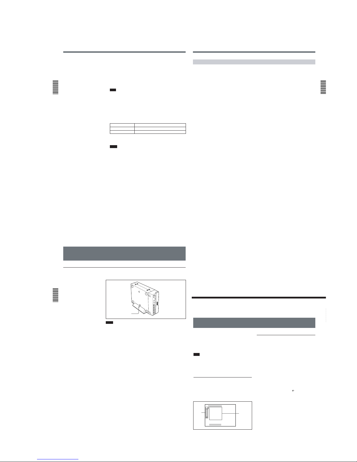
1-9
Recording
Chapter
2 Playback
and Recording
38
(GB) Chapter 2 Playback and Recording
5
Select an input signal by switching the INPUT SELECT selector on
this unit.
DV: to record input signals from the DV IN/OUT connector
S VIDEO: to record input signals from the S VIDEO connector on the
INPUT jacks
VIDEO: to record input signals from the VIDEO jack on the INPUT
jacks
Note
Do not change the selector setting during recording. Otherwise, noise
is output to the picture and sound and that portion will not be recorded
properly.
6
When the player is connected to the INPUT jacks on this unit, select
the audio mode.
Select the desired mode by setting AUDIO MODE on the AUDIO SET
menu.
Audio mode Set the menu to
4-channel mode FS32K
2-channel mode FS48K
For details on the AUDIO SET menu, see “AUDIO SET menu” on page 44
(GB).
Notes
•In the DVCAM format, there are two audio modes, with either two
channels at 48 kHz or four channels at 32 kHz. It is not possible to
select other modes (for example with two channels at 32 kHz).
•When recording in 4-channel mode on this unit, audio signals are
recorded only in channels 1/2. When you are going to dub sounds
onto the tape, set AUDIO MODE to FS32K. (To dub a sound onto a
tape (audio dubbing), you need another VCR that has audio dubbing
capabilities. This unit does not have this function.)
•
During recording, you cannot change the audio mode selection.
Chapter 2
Playback
and Recording
Chapter 2 Playback and Recording39 (GB)
Recording Procedure
This section describes the procedures used to record signals sent from
another VCR to this unit. For details on the procedures required when
using a computer as a player, refer to the instruction manual of your
computer or the user’s manuals of the software installed in it.
1
After checking that the REC/SAVE switch is set to REC, checking the
tape for slack and confirming that the q indicator is off, hold the
cassette so that the tape window is facing upward, then insert it into
this unit.
For details on the REC/SAVE switch and checking the tape for slack, see
“Notes on Video Cassettes” on page 15 (GB).
The cassette is automatically loaded into the unit and the tape will stop.
2
Press the playback button on the player.
The player starts playback.
3
Press the PLAY button while holding down the REC button.
The unit starts recording and the index is marked.
To stop recording
Press the STOP button on the unit.
To pause recording
Press the PAUSE button on the unit.
To display useful data for recording on the monitor screen
Press the DISPLAY button on the Remote Commander.
For details on displayed data, see “Displaying various data”
on page 26 (GB).
Recording
Chapter
2 Playback
and Recording
40
(GB) Chapter 2 Playback and Recording
Installing the Unit Vertically
To install the unit
Put the unit into the supplied rack as illustrated below. You can install it
either standing on its left side or on its right side.
Notes
•Be sure to use the supplied rack. Without the rack, the unit may topple
over and may be damaged or may cause injury.
•Install the unit on a flat place.
•When inserting a cassette, especially a mini cassette, hold it until it is
loaded into the unit. Otherwise the cassette may fall out and the tape may
be damaged.
For details on inserting a cassette, see “Notes on Video Cassettes” on page 15
(GB).
Align the F on the unit
with the f
on the rack.
Chapter 3
Adjusting
and Setting
Through
Menus
Chapter 3 Adjusting and Setting Through Menus41 (GB)
Chapter
3
Adjusting and Setting
Through Menus
Operating the Menus
VTR SET
REC MODE
FF/ REW SPD
STI LL T IME
FROM STI LL
FROM REC P
DV EE OUT
STI LL P ICT
[MENU] : END
VTR
A
DISP
CM
ETC
The unit allows you to set various parameters in the
menus. Before you start using the unit, set the internal
clock in CLOCK SET on the OTHERS menu. Except
for clock setting, you can use all other factory-set
default parameters but change them as needed.
Note
If the internal backup battery is exhausted, the menu
settings will be initialized. The internal backup battery
is fully charged if you connect the power to the unit
for about 10 hours. The menu settings will be kept for
about one month.
Displaying the menu
Press the MENU button on the Remote Commander.
The menu is superimposed on the analog video output.
Changing the menu settings
1
Pressing the M/m buttons on the Remote
Commander, select the menu icon you want to
change, then press the SET button on the Remote
Commander.
2
Pressing the M/m buttons, select the submenu you
want to change, then press the SET button.
3
Pressing the M/m buttons, change the setting.
4
Press the SET button to return to the submenu.
5
Repeat steps 2 to 4, as needed.
To return to step 1
Pressing the M/m buttons, select
RETURN, then
press the SET button.
To exit from the menu
Press the MENU button again.
Icons
Submenus
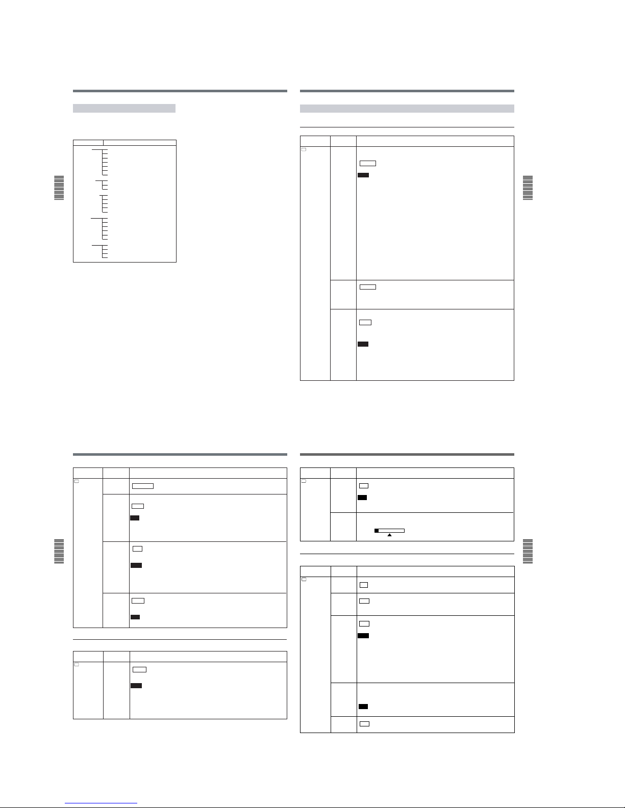
1-10
Operating the Menus
Chapter
3 Adjusting
and Setting Through
Menus
42
(GB) Chapter 3 Adjusting and Setting Through Menus
Menu Organization
The menu of this unit consists of the following menus
and submenus.
Menu
Submenu (page)
DISPLAY SET qREMAIN
(page 45 (GB))
DATA CODE
(page 45 (GB))
COLOR BAR
(page 45 (GB))
a)
DATE DISP
(page 45 (GB))
TIME DISP
(page 45 (GB))
AUDIO SET AUDIO MODE
(page 44 (GB))
JOG AUDIO
(page 45 (GB))
AUDIO MIX
(page 45 (GB))
CM SET CM SEARCH
(page 46 (GB))
TITLE DISP
(page 46 (GB))
LABEL DISP
(page 46 (GB))
TAPE LABEL
(page 46 (GB))
ITEM ERASE
(page 47 (GB))
ERASE ALL
(page 48 (GB))
VTR SET REC MODE
(page 43 (GB))
FF/REW SPD
(page 43 (GB))
STILL TIME
(page 43 (GB))
FROM STILL
(page 44 (GB))
FROM REC P
(page 44 (GB))
DV EE OUT
(page 44 (GB))
STILL PICT
(page 44 (GB))
OTHERS DV IN TC
(page 49 (GB))
TC FORMAT
(page 49 (GB))
b)
CLOCK SET
(page 49 (GB))
HRS METER
(page 49 (GB))
a) COLOUR BAR for PAL model
b)
available only when you use an NTSC formatted signal
Chapter 3
Adjusting
and Setting
Through
Menus
Chapter 3 Adjusting and Setting Through Menus43 (GB)
Icon/Menu
Submenu
Setting
(page)
VTR
VTR SET
REC MODE
Switches the recording mode between DVCAM and DV (SP mode only). When you play
back a tape, the DVCAM/DV setting will be automatically switched; you do not need to use
this item.
DVCAM : Records in DVCAM format.
DV SP: Records in DV format (SP mode).
Notes
• This unit is not compatible with playing or recording in LP mode of the consumer DV format.
• You cannot change the setting while recording.
• It is recommended that you record in the DVCAM format. There are some limitations with
respect to DV recording depending on machine specifications and the consumer DV
format as follows:
– The head system is optimized for DVCAM recording. A DV recording overwrites the last
track just before the beginning of the recording. As a result, at the border of these two
recorded portions, picture and sound may be distorted.
– The sound will be recorded unsynchronized. (unlock mode)
– The time code is fixed to the drop frame mode. (only for NTSC)
– The DV IN TC setting on the OTHERS menu turns invalid. The unit records internal time
code.
• If you dub a consumer DV tape from the DV IN/OUT connector on this unit, keep the
following in mind:
– Set the REC MODE to DV SP. If the REC MODE has been set to DVCAM, a tape with
an invalid format (recording speed: DVCAM, sound: unsynchronized, unlock mode) will
be made. (The unit cannot convert unlock mode sound to lock mode sound.)
– If you edit a tape with an invalid format in the DSR-70/70P, DSR-80/80P, DSR-85/85P,
DSR-2000/2000P, etc., there may be some restrictions.
For details on DVCAM/DV format compatibility, see “Compatibility of DVCAM and DV
Format” on page 55 (GB).
FF/REW SPD
Selects the tape transport mode in fast-forward and rewind.
FF/REW : Fast-forwards or rewinds the tape at maximum speed without displaying the
picture.
SHUTTLEMAX: Fast-forwards or rewinds the tape at maximum speed (about 14 times
normal speed for NTSC; about 17 times normal speed for PAL) while displaying the
picture.
STILL TIME Selects the time to switch to the tape protection mode from the still mode.
30 SEC: 30 seconds
1 MIN : 1 minute
2 MIN: 2 minutes
3 MIN: 3 minutes
5 MIN: 5 minutes
Notes
• If the unit is left in playback pause mode for a long time, the tape or the video heads may
be damaged or the video heads may become clogged. Select the shortest time possible
—particularly when using a Mini-DV cassette that is longer than 60 minutes, select 30
SEC or 1 MIN.
• When the setting is changed, the first tape protection mode change uses the time setting
from before the settings were changed. From the second tape protection mode change,
the new time setting is used.
Menu Contents
Initial settings are indicated with rectangles.
VTR SET menu
(Continued)
Operating the Menus
Chapter
3 Adjusting
and Setting Through
Menus
44
(GB) Chapter 3 Adjusting and Setting Through Menus
Icon/Menu
Submenu
Setting
(page)
VTR
VTR SET
FROM REC
P
Selects the tape protection mode that the system changes to after the recording has been
paused for more than five minutes.
STOP : Stops the tape.
REC PAUSE: Maintains the recording pause mode.
Note
When the recording pause mode continues for a long time after you select REC PAUSE, the
tape may be damaged or the video heads may be damaged or clogged. If there is no other
reason to do this, select STOP. Particularly when you use a Mini-DV cassette that is longer
than 60 minutes, select STOP.
DV EE OUT
(page 36 (GB))
Selects the output from the DV IN/OUT connector in the EE mode.
OFF : Does not output DV signals converted from analog input signals.
ON: Outputs DV signals from the DV IN/OUT connector that were converted from selected
analog input signals.
Notes
• During playback, the unit outputs DV signals from the DV IN/OUT connector regardless of
this setting.
• When you connect a computer to the DV IN/OUT connector, depending on your computer
software, the selected analog input signals may be output to the computer even if this item
is set to OFF.
STILL PICT
FROM STILL Selects the tape protection mode which to change the mode from the still mode.
STEP FWD : Forwards one frame.
STOP: Stops the tape.
AUDIO SET menu
A
AUDIO SET
Icon/Menu
Submenu
Setting
(page)
AUDIO
MODE
(page 38 (GB))
Selects the audio mode.
FS32K : Switches the audio mode to the four channel mode (12-bit mode).
FS48K: Switches the audio mode to the two channel stereo mode (16-bit mode). (This
setting records the sound in all audio ranges, providing a high-quality sound recording.)
Notes
• This item is disabled when inputting signals from the DV IN/OUT connector.
• You cannot display the selection screen while in the recording mode.
• Noise may occur at the moment you switch the audio mode.
• When you are going to dub sounds onto the tape, set this item to FS32K. (To dub a sound
onto a tape, you need another VCR which has audio dubbing capabilities. This unit does
not have this function.)
Selects the image displayed in the still mode.
AUTO : Displays an optimized image according to the movement in the image.
FRAME: Displays a frame image.
FIELD: Displays a field image.
Note
If you select FIELD, the image of field 2 is displayed.
Chapter 3
Adjusting
and Setting
Through
Menus
Chapter 3 Adjusting and Setting Through Menus45 (GB)
DISPLAY SET menu
Icon/Menu
Submenu
Setting
(page)
DISP
DISPLAY
SET
qREMAIN
(page 27 (GB))
Selects whether or not to display the tape remaining time on the analog video output.
ON : Displays the tape remaining time.
OFF: Does not display the tape remaining time.
DATA CODE
(page 25 (GB))
Selects whether or not to display the data codes on the analog video output.
OFF : Does not display the data codes.
DATE: Displays the date and time when recorded.
CAMERA: Displays the camera data.
COLOR BAR
(for NTSC model) /
COLOUR BAR
(for PAL model)
Selects whether or not to display the color bars.
OFF : Does not display the color bars.
ON: Displays the color bars.
Notes
• You cannot display the color bars while the unit is playing the tape or when the INPUT
SELECT selector is set to DV.
• The color bars are displayed only on the analog video output.
• If you record when the color bars are displayed, the color bars will also be recorded on
the tape.
• Do not use the color bars output from the OUTPUT jacks as a reference signal.
• The reference sound signals are not output even if this item is set to ON.
• This item will be automatically set to OFF if you set the INPUT SELECT selector to DV or
you operate the tape transport control that display the pictures recorded on the tape.
DATE DISP
Selects the date display in the search screen, the data code display and so on.
Y/M/D: Displays YY/MM/DD (year/month/day).
M/D/Y: Displays MM/DD/YY (month/day/year).
D/M/Y: Displays DD/MM/YY (day/month/year).
Note
The default is M/D/Y for the NTSC model; D/M/Y for the PAL model.
TIME DISP
Selects the time display in the search screen, the data code display and so on.
24H : Displays 24-hour time.
12H: Displays 12-hour time.
A
AUDIO SET
Icon/Menu
Submenu
Setting
(page)
AUDIO MIX
(page 23 (GB))
Adjust the balance of the analog audio output level between channels 1/2 and channels 3/4
during playback.
Press the M/m buttons to move the bar, then press the SET button.
CH12CH3
4
JOG AUDIO Turns sound output on/off when the tape is played at a speed other than normal.
OFF : Does not output the sound when playing a tape at a speed other than normal.
ON: Outputs the sound when playing a tape at a speed other than normal.
Note
Even if you have set this item to ON, the sound may not be output or may be interrupted
depending on the recording format or tape conditions.
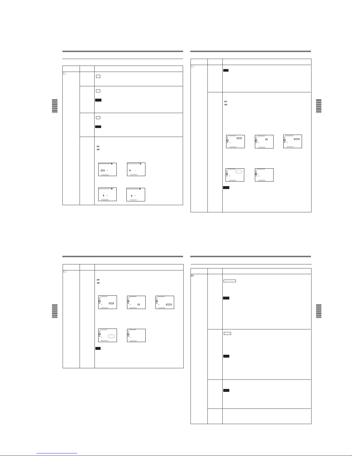
1-11
Operating the Menus
Chapter
3 Adjusting
and Setting Through
Menus
46
(GB) Chapter 3 Adjusting and Setting Through Menus
Selects whether or not to display the tape label.
ON : Displays the tape label for about five seconds when a cassette that has a tape label
is inserted.
OFF: Does not display the tape label.
Notes
• The tape label is displayed only on the analog video output.
• If the tape label has been made with an other VCR or camcorder, this unit cannot display
a tape label that includes a font that the unit does not have.
LABEL DISP
Icon/Menu
Submenu
Setting
(page)
CM SET menu
CM
CM SET
CM SEARCH
(page 29 (GB))
Selects the mode which searches recordings.
ON : Searches recordings using the cassette memory. (If the tape does not have cassette
memory, the beginning of recording is searched for using the search signals on the
tape.)
OFF: Always searches recordings using the search signals on the tape.
TITLE DISP Selects whether or not to display the title.
ON : Displays the superimposed title for about five seconds when the unit plays back the
point where the title is recorded.
OFF: Does not display the title.
Notes
• The title that has been made with the camera or an external device is displayed. You
cannot make a title with this unit.
• The unit cannot display a font that the unit does not have.
• The title is displayed only on the analog video output.
TAPE LABEL Makes a tape label. (You can enter up to 10 characters on a tape label.)
If you select this item, one of the following symbols appears. If no cassette is loaded,
nothing is displayed.
: Tape with cassette memory
: Tape without cassette memory
You can make a tape label as follows:
1 On the TAPE LABEL screen, select the line that has the alphabet character you want by
pressing the M/m and SET buttons. (The cursor moves to the first character of the line.)
2 Select a character by pressing the M/m and SET buttons. (The selected character is
entered. To erase a character, select [ P ]; the last character is erased.)
TAPE LABEL
__________
A
F
K
P
U
Z
B
G
L
Q
V
&
C
H
M
R
W
D
I
N
S
X
?
E
J
O
T
Y
!
1
6
'
[
[
2
7
.
S
3
8
,
E
4
9
/
T
5
0
–
]
]
[MENU] : END
TAPE LABEL
__________
A
F
K
P
U
Z
B
G
L
Q
V
&
C
H
M
R
W
D
I
N
S
X
?
E
J
O
T
Y
!
1
6
'
[
[
2
7
.
S
3
8
,
E
4
9
/
T
5
0
–
]
]
[MENU] : END
,
TAPE LABEL
__________
A
F
K
P
U
Z
B
G
L
Q
V
&
C
H
M
R
W
D
I
N
S
X
?
E
J
O
T
Y
!
1
6
'
[
[
2
7
.
S
3
8
,
E
4
9
/
T
5
0
–
]
]
[MENU] : END
TAPE LABEL
S
_________
A
F
K
P
U
Z
B
G
L
Q
V
&
C
H
M
R
W
D
I
N
S
X
?
E
J
O
T
Y
!
1
6
'
[
[
2
7
.
S
3
8
,
E
4
9
/
T
5
0
–
]
]
[MENU] : END
,
Operating the Menus
Chapter
3 Adjusting
and Setting Through
Menus
48
(GB) Chapter 3 Adjusting and Setting Through Menus
Icon/Menu
Submenu
Setting
(page)
CM
CM SET
CM SET
CM SEARCH
TI TLE DISP
LABEL DI SP
TAPE LABEL
ITEM ERASE
ERASE ALL
RETURN
[MENU] : END
RETURN
OK
VTR
A
DISP
CM
ETC
CM SET
CM SEARCH
TI TLE DISP
LABEL DI SP
TAPE LABEL
ITEM ERASE
ERASE ALL
RETURN
[MENU] : END
VTR
A
DISP
CM
ETC
RETURN
OK
,
CM SET
CM SEARCH
TI TLE DISP
LABEL DI SP
TAPE LABEL
ITEM ERASE
ERASE ALL
RETURN
[MENU] : END
RETURN
EXECUTE
VTR
A
DISP
CM
ETC
,
CM SET
CM SEARCH
TI TLE DISP
LABEL DI SP
TAPE LABEL
ITEM ERASE
ERASE ALL
RETURN
[MENU] : END
ERASING
VTR
A
DISP
CM
ETC
CM SET
CM SEARCH
TI TLE DISP
LABEL DI SP
TAPE LABEL
ITEM ERASE
ERASE ALL
RETURN
[MENU] : END
COMPLETE
VTR
A
DISP
CM
ETC
,
ERASE ALL
Erases all items in the cassette memory.
If you select this item, one of the following symbols appears. If no cassette is loaded,
nothing is displayed.
: Tape with cassette memory
: Tape without cassette memory
Erase all items in the cassette memory as follows:
1 To erase all items, select OK, otherwise select RETURN. (If you select OK, the unit will
check again to see if you really want to erase all items.)
2 To erase all items, select EXECUTE, otherwise select RETURN. (If you select
EXECUTE, the ERASING message will flash, and the unit starts erasing all items in the
cassette memory. While the ERASING message is flashing, you cannot use the M/m or
SET buttons. After all items have been erased, the COMPLETE message appears.
Press the M/m button to erase the COMPLETE message.)
Note
You cannot erase all items in the cassette memory in the following cases:
• The unit does not have a tape inserted or the tape is being unloaded.
• The tape does not have cassette memory.
• The tape is write-protected.
• The tape is being recorded.
•
The cassette memory is being used.
Chapter 3
Adjusting
and Setting
Through
Menus
Chapter 3 Adjusting and Setting Through Menus49 (GB)
OTHERS menu
Icon/Menu
Submenu
Setting
(page)
OTHERS
DV IN TC
Selects whether to record internal time code or external time code while the unit records the
signals input from the DV IN/OUT connector in DVCAM format.
INTERNAL : Records the time code generated by the internal time code generator. (If no
time code is recorded on the tape, the unit records time code from 00:00:00:00. If there
is time code already recorded on the tape, the unit records continuous time code from
this point.)
EXTERNAL: Records the time code with video and audio signals input from the DV IN/
OUT connector.
Notes
• When you set the REC MODE on the VTR SET menu to DV SP, this item cannot be used.
Even if it is once set to EXTERNAL, the setting turns invalid and the unit records the
internal time code when you set REC MODE on the VTR SET menu to DV SP.
• When this item is set to EXTERNAL, the INPUT SELECT selector on the front panel is set
to DV, and no signal is input from the DV IN/OUT connector, if you start recording, bars (—
:—:—:—) are recorded as time code. At the point that inputting of a signal begins, the time
code of that signal will be recorded.
• If you set this item to EXTERNAL and the external time code input is discontinuous or
does not advance correctly, recording or displaying the time code on this unit may not be
done correctly. If there is a discontinuous time code on your recorded tape, you may not
be able to edit or search correctly, depending on the device used to edit.
CLOCK SET
(page 37 (GB))
Sets the internal clock of the unit.
Pressing the M/m and SET buttons, sets the time (year, month, day, hour and minute).
(When you set the minute, the second count will start from 00.)
Notes
• This item cannot be set during recording.
•
Regardless of the DATE DISP setting on the DISPLAY SET menu, the date for CLOCK
SET is displayed in the Y/M/D order.
• The internal backup battery will be fully charged in about 10 hours when power is provided
to the unit. A fully charged internal backup battery can run the internal clock for about one
month without the power provided through the AC adaptor.
HRS METER
(page 53 (GB))
Displays the accumulated time counts (by the digital hours meter) in units of 10 hours or 10 counts.
OPERATION: Power on duration
DRUM RUN: Drum rotation duration
TAPE RUN: Tape run duration
THREADING: Tape unthreading count
TC FORMAT Selects the frame mode.
AUTO : Automatically sets the frame mode in accordance with the inserted cassette. (If
nothing is recorded on the tape, the mode is set to the non-drop frame mode. If the unit
cannot read the frame mode correctly in the tape, the unit will use the frame mode that
was set in the last position it was able to read correctly on the tape. If you turn the
power on/off or remove the tape, the mode of the last position it was able to read
correctly is cleared and the mode is set to the non-drop frame mode.)
DF: Selects the drop frame mode.
NDF: Selects the non-drop frame mode.
Notes
• When the NTSC/PAL select switch is set to PAL, the unit works as a PAL model.
Therefore while recording in the DVCAM format, the time code generated by the unit turns
to the non-drop frame mode. Even if an NTSC formatted signal is input from the DV IN/
OUT connector, the time code generated by the unit is non-drop frame mode as long as
the switch is set to PAL, regardless of this item setting. If you intend to set the unit to
generate the time code in the drop frame mode, set the NTSC/PAL select switch to NTSC.
• Regardless of this setting, the frame mode is set to drop frame when you record in DV
format (Only for NTSC).
Chapter 3
Adjusting
and Setting
Through
Menus
Chapter 3 Adjusting and Setting Through Menus47 (GB)
Icon/Menu
Submenu
Setting
(page)
CM
CM SET
TAPE LABEL 3 Repeat steps 1 and 2. After entering all characters for the tape label, select [SET].
Note
The unit cannot display the TAPE LABEL screen in the following cases:
• The unit does not have a tape inserted or the tape is being unloaded.
• The tape does not have cassette memory.
• The cassette memory is full of data other than the tape label data.
• The tape is write-protected.
• The tape is being recorded.
• The cassette memory is being used.
ITEM ERASE Erases a cassette memory item.
If you select this item, one of the following symbols appears. If no cassette is loaded,
nothing is displayed.
: Tape with cassette memory
: Tape without cassette memory
The available items are as follows:
INDEX ALL: Erases the index data.
TITLE ALL: Erases the title data.
DATE ALL: Erases the date data.
PHOTO ALL: Erases the photo data.
You can erase an item as follows:
1 Select an item to erase by pressing the M/m and SET buttons.
2 To erase the item, select OK, otherwise select RETURN. (If you select OK, the unit will
check again to see if you really want to erase the item.)
3 To erase the item, select EXECUTE, otherwise select RETURN. (If you select
EXECUTE, the ERASING message will flash, and the unit will start erasing the item in
the cassette memory. While the ERASING message is flashing, you cannot use the M/m
or SET buttons. After the item has been erased, the COMPLETE message appears.
Press the M/m button to erase the COMPLETE message.)
Notes
• You cannot make a title, mark the date for date search, or record in the photo mode with
this unit.
• You cannot erase an item in the cassette memory in the following cases:
– The unit does not have a tape inserted or the tape is being unloaded.
– The tape does not have cassette memory.
– The tape is write-protected.
– The tape is being recorded.
– The cassette memory is being used.
CM SET
ITEM ERASE
INDEX ALL
TI TLE ALL
DATE ALL
PHOTO ALL
RETURN
[MENU] : END
RETURN
OK
VTR
A
DISP
CM
ETC
CM SET
ITEM ERASE
INDEX ALL
TI TLE ALL
DATE ALL
PHOTO ALL
RETURN
[MENU] : END
RETURN
OK
VTR
A
DISP
CM
ETC
,
CM SET
ITEM ERASE
INDEX ALL
TI TLE ALL
DATE ALL
PHOTO ALL
RETURN
[MENU] : END
ERASING
VTR
A
DISP
CM
ETC
,
CM SET
ITEM ERASE
INDEX ALL
TI TLE ALL
DATE ALL
PHOTO ALL
RETURN
[MENU] : END
RETURN
EXECUTE
VTR
A
DISP
CM
ETC
CM SET
ITEM ERASE
INDEX ALL
TI TLE ALL
DATE ALL
PHOTO ALL
RETURN
[MENU] : END
COMPLETE
VTR
A
DISP
CM
ETC
,
(Continued)

1-12
Troubleshooting
Chapter
4 Maintenance
50
(GB) Chapter 4 Maintenance
Chapter
4
Maintenance
Troubleshooting
Symptom Cause/Remedy
The power cannot be turned on. The AC adaptor is disconnected. t Connect the AC adaptor.
The unit will not operate even if the power
has been turned on.
• Moisture condensation has occurred. t Turn off the power and disconnect the
AC adaptor. Connect the AC adaptor after about one minute and turn on the
power. Then, if there is a cassette in the unit, remove the cassette and keep the
cassette lid open, power on the unit and leave it on for more than one hour.
• The cassette is not inserted straight. t Insert it straight.
The cassette cannot be inserted.
• There is moisture condensation on the head drum. t Keep the cassette lid
open and turn the power on. Then, wait more than one hour.
• The cassette is not inserted straight. t Insert it straight.
• Another cassette has been loaded already. t Remove the cassette and insert
the one you want to load.
It takes time to eject the cassette.
This is not a malfunction. t This unit ejects the cassette slowly to protect the tape.
No picture.
The video heads are dirty. t Clean the video heads using the supplied cleaning cassette.
Noise appears on the screen.
• A damaged cassette is inserted. t Insert another cassette.
• The video heads are dirty. t Clean the video heads using the supplied
cleaning cassette.
No picture via the DV jack.
• Reconnect the i.LINK cable (DV cable) (not supplied).
• The INPUT SELECT selector is set to other than DV. t Set it to DV.
The audio is noisy.
A damaged cassette is inserted. t Insert another cassette.
Pause is released automatically. Pause mode is automatically released to protect the tape.
Please check the following before contacting your Sony dealer.
The picture and sound are muted in the
EE or recording mode.
The NTSC/PAL select switch setting is not appropriate. t Set it to a suitable
position for the color system of the input signals.
The Remote Commander or remote
control unit does not work.
The REMOTE CONTROL switch setting is not appropriate. t Set it to a suitable
position for the device you use.
Though DV IN TC on the OTHERS menu
was set to EXTERNAL, the time code of
the signals input from the DV IN/OUT
connector cannot be recorded.
The REC MODE on the VTR SET menu is set to DV SP. t Set the REC MODE
to DVCAM.
When the unit is recording an NTSC
formatted signal input from the DV IN/OUT
connector in DVCAM format, even if the
TC FORMAT on the OTHERS menu is set
to DF, the time code is recorded in nondrop frame mode.
The NTSC/PAL select switch is set to PAL. t Set it to NTSC.
Chapter
4 Maintenance
Chapter 4 Maintenance51 (GB)
Alarm Messages
If an error occurs, a caution appears on the analog video outputs when you set the unit to output signals with data
items. Check them with the following list.
For details on data items, see “Displaying various data” on page 26 (GB).
Monitor
Indicator lamp (flash)
a)
Description/Recovery
%
Moisture condensation (without a cassette) t Keep the cassette lid
open and turn the power on, then wait more than one hour.
%Z
Moisture condensation (with a cassette) t Remove the cassette and
keep the cassette lid open and turn the power on, then wait more than
one hour.
Q
NO TAPE
You tried to record without a cassette inserted. t Insert a cassette.
Q
The tape is reaching the end during recording. t Provide a new
cassette.
QZ
TAPE END
The tape reached the end and still tried to record. t Rewind the tape or
replace the tape with a new one.
QZ
The cassette is write-protected (The REC/SAVE switch is set to SAVE) and
you tried to record. t Set the REC/SAVE switch to REC or use another
cassette
(See page 16 (GB))
.
CLOCK SET
You did not set the clock when you turned on the unit.
t
Set the clock
with the menu
(See page 49 (GB))
.
COPY
INHIBIT
Slow flashing
You tried to record a copyright-protected source.
t You cannot record a copyright-protected source
(See page 19 (GB))
.
Rapid flashing
The video heads are clogged. t Clean the video heads with the supplied
cleaning cassette. (The unit detects if the video heads are clean only
before recording. If the video heads get clogged during recording, the unit
cannot detect it.)
x
Y
Displayed
alternately
CLEANING
CASSETTE
Z
Rapid flashing
The unit is running the self-diagnostics
(See page 54 (GB))
. This caution
display ceases when you turn on/off the power of the unit.
a) The indicator flashes 3.2 times per second in the rapid flashing mode and flashes 0.8 time per second in the slow flashing
mode.
Rapid flashing
Rapid flashing
Slow flashing
Slow flashing
Slow flashing
CAUTION
Slow flashing
Notes on Use
Chapter
4 Maintenance
52
(GB) Chapter 4 Maintenance
Notes on Use
Notes on the video cassette recorder
Do not install the unit in a place subject to
direct sunlight or heat sources
If you do, its cabinet, mechanical parts, etc., may be
damaged.
Do not install the unit in an extremely hot
place
If the unit is left in a car parked with its windows
closed (especially in summer), its cabinet may be
damaged or it may not work correctly.
If the unit is brought directly from a cold to a
warm location
Moisture may condense inside the unit and cause
damage to the video head and tape. If you use the unit
in a place subject to direct cold currents from an air
conditioner, moisture may also condense inside the
unit.
Do not place a heavy object on the unit
The cabinet may be damaged, or the unit may not work
correctly.
Do not handle the unit roughly
Avoid rough handling or mechanical shock.
To avoid damaging the cabinet finish
Plastic is often used for the surface finishing of the
unit. Do not spray a volatile solvent such as an
insecticide toward the cabinet or place rubber or vinyl
products on the cabinet for a long time. If you do, the
finish of the cabinet may be damaged or the coating
may come off.
Do not clean the cabinet with thinner or
benzine
The cabinet may be damaged or its coating may come
off. When you use a chemical-impregnated cloth, use
it according to its directions.
Clean the cabinet with soft dry cloth
When the cabinet is very dirty, clean it with a soft dry
cloth lightly moistened with a mild detergent solution
and finish it with a dry cloth.
Do not put magnetic objects close to the unit
Magnetic fields may damage the recording.
To prevent electromagnetic interference
caused by radio communication equipment
such as cellular phones, transceivers, etc.
The use of the radio communication equipment such as
cellular phones or transceivers near the unit may cause
a malfunction and can affect the audio/video signals.
The cellular phones or transceivers near the unit should
be switched off.
Do not use the unit in an area exposed to
radiation
A malfunction may occur.
Checking the video heads every 1000 hours
A VCR is a high-precision piece of equipment that
records and plays back the picture on a magnetic tape.
In particular, the video heads and other mechanical
parts become dirty or worn. To maintain a clean
picture, we recommend maintenance every 1000 hours,
though the conditions of use may differ depending on
temperature, humidity, dust, etc.
Cleaning of the video heads
If the video heads are contaminated, the pictures
cannot be recorded properly or the playback pictures
become noisy. If the following phenomena occur, use
the cleaning cassette (supplied) to clean the heads.
•Square-shaped noise appears on the playback picture.
•A part of the playback picture does not move.
•The playback picture does not appear on the screen.
To use the cleaning cassette
Refer to your cleaning cassette’s operating instructions.
After prolonged use, the video heads may become
worn out. If optimum picture quality is not restored
even after you have cleaned the video heads with the
cleaning cassette, the video heads may have worn out.
In that case, you have to replace the video heads with
new ones. Please consult your Sony dealer.
Symptoms caused by contaminated video heads
Normal picture
If these images appear on the
screen, use the cleaning cassette.
Chapter
4 Maintenance
Chapter 4 Maintenance53 (GB)
Notes on the video cassettes
If the cassette memory function does not work
Reinsert the cassette a few times. The terminal portion
of the cassette may be dusty or dirty.
Cleaning the terminal
If the terminal of the cassette gets dirty, or dust sticks
to the terminal, the unit may not work correctly.
Clean the terminal with a swab once every ten times
you eject a cassette.
When affixing a label on the cassette
Be sure to affix a label only on the correct location so
as not to cause malfunction of the unit.
After using a cassette
After use, please be sure to rewind the tape completely
(to prevent picture and sound distortion). Return it to
its case and store it in an upright position.
About moisture condensation
If the unit or tape is brought directly from a cold to a
warm location, moisture may condense inside or
outside the unit or tape. If you use the tape or video
heads in this condition, the tape may adhere to the
head drum, and the video heads or the tape may be
damaged, or a malfunction may occur.
Moisture condensation is likely to occur under the
following conditions:
•The unit or tape is brought from the cold outdoors to
a warm indoor location.
•The unit or tape is brought from the air-conditioned
indoors to the hot outdoors.
•The unit is used in a place subject to cold currents
from an air conditioner.
When bringing the unit or tape from a cold place to a
warm place or vice versa, put it in a plastic bag and
seal the bag tightly. After bringing it into the new
place, leave the bag on for more than one hour, and
remove the bag when the air temperature inside it has
reached the temperature surrounding it.
If moisture condensation occurred
You cannot operate the unit except to press the EJECT
button, and the cassette cannot be inserted. If this
occurs, turn on the power to remove the cassette, then
keep opening the cassette lid, and finally wait more
than one hour for the moisture to evaporate.
Digital hours meter
The digital hours meter keeps cumulative counts of the
total operation time, the head drum rotation time, the
tape running time and the number of unthreading
operations. These counts can be displayed on the
monitor screen. Use them as guidelines for scheduling
maintenance.
In general, consult your Sony dealer about necessary
periodic maintenance checks.
The digital hours meter has the following four display
modes and you can check them in HRS METER of the
OTHERS menu (See page 49 (GB)).
•OPERATION mode
The cumulative total hours of operating time is
displayed in 10-hour increments.
•DRUM ROTATION mode
The cumulative total hours of drum rotation with tape
threaded is displayed in 10-hour increments.
•TAPE RUN mode
The cumulative total hours of tape running time is
displayed in 10-hour increments.
•THREADING mode
The cumulative number of tape unthreading
operations is displayed in 10-operation increments.
Terminal
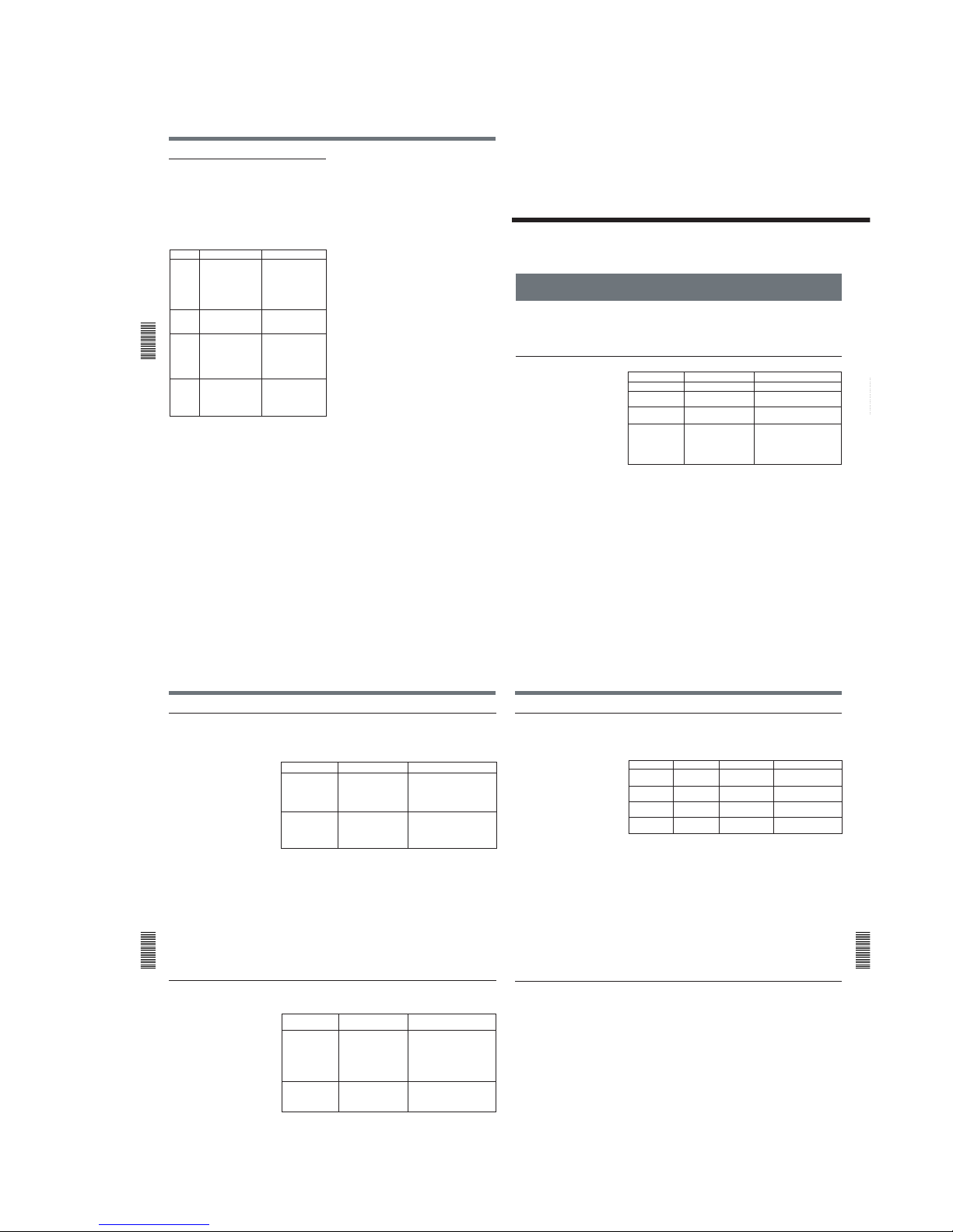
1-13
Notes on Use
Chapter
4 Maintenance
54
(GB) Chapter 4 Maintenance
Self-diagnostics function
The unit has a self-diagnostics display function.
This function displays the current condition of the unit
as a five-digit code (a combination of a letter and
numbers) on the analog video output. If a five-digit
code is displayed, check the following code chart. The
last two digits (indicated by ss) will differ depending
on the state of your unit.
If you are unable to resolve the problem, or a code
other than those in the above chart appears, contact
your Sony dealer or local authorized Sony service
facility and inform them of the number.
Code
C:21:ss
C:22:ss
C:31:ss
C:32:ss
Symptom
Moisture
condensation has
occurred.
The video heads are
dirty.
To prevent the unit
from malfunctioning,
the self-diagnostics
function has taken
over.
To prevent the unit
from malfunctioning,
the self-diagnostics
function has taken
over.
Remedy
Remove the cassette
and keep the cassette
lid open and turn the
power on. After waiting
more than one hour,
insert the cassette
again.
Clean the heads using
the cleaning cassette
(supplied).
• Remove the cassette,
or turn on/off the unit.
• Disconnect the AC
adaptor. After
reconnecting it,
operate the unit.
• Turn on/off the unit.
• Disconnect the AC
adaptor. After
reconnecting it,
operate the unit.
Appendix
Appendix55 (GB)
Appendix
Compatibility of DVCAM and DV Format
The DVCAM format was developed as a more reliable and higher end
format than the consumer DV format. Here we explain the DVCAM and
DV formats: the differences, compatibility and limitations on editing.
Differences between DVCAM and DV format
1) There are two modes for audio recording; Lock mode and Unlock mode. In
Lock mode, the sampling frequencies of audio and video are synchronized. In
Unlock mode, which the consumer DV format adopts, the two sampling
frequencies are independent. The lock mode maintains high compatibility with
the higher formats and is more effective than unlock mode in digital processing
and smooth transition during audio editing.
2) This unit cannot record in DV format with 16 bit – 32 kHz or 44.1 kHz.
3) The user bits cannot be set on this unit.
Item
Track pitch
Audio sampling
frequency
Audio recording
mode
1)
Time code system
DVCAM
15 µm
12 bit: 32 kHz
16 bit: 48 kHz
Lock mode
NTSC; SMPTE time
code (DF/NDF/including
user bits)
3)
PAL; EBU time code
(including user bits)
3)
DV
10 µm
12 bit: 32 kHz
16 bit: 32 kHz, 44.1 kHz, 48 kHz
2)
Unlock mode
Drop frame mode (NTSC)
without user bits
Compatibility of DVCAM and DV Format
Appendix
56
(GB) Appendix
DVCAM and DV cassettes
Both DVCAM and DV cassettes can be used on DVCAM or DV video
equipment. The recording format is defined according to recorder format
as described below.
•This unit can record in DV format. (SP mode only)
•This digital videocassette recorder complies with the DVCAM format.
Though DV cassettes can be used for recording, we recommend that you
use DVCAM cassettes. Particularly when you use a Mini-DV cassette
that is longer than 60 minutes, do not play back the tape repeatedly (i.e.,
when editing). Set STILL TIME to 1 MIN or 30 SEC (See page 43 (GB)),
and FROM REC P to STOP (See page 44 (GB)).
•If you use a DV cassette to record images in the DVCAM format, the
recording time will be reduced to 2/3 of the time indicated on the DV
cassette.
•If you use a DVCAM cassette to record images in the DV format (SP
mode), the recording time will be extended to 1.5 times the time indicated
on the DVCAM cassette.
Compatibility on playback
Some tapes cannot be played on DVCAM or DV video equipment.
Recorder format
DVCAM
(If the REC MODE
on the VTR SET
menu is set to
DVCAM on this unit.)
DV
(If the REC MODE
on the VTR SET
menu is set to DV SP
on this unit.)
Cassette format
DVCAM
DV
DVCAM
DV
Recording format
DVCAM
DV
Tape
DV-formatted
DVCAM-formatted
On DV video equipment
(Consumer VCR)
Can be played back.
(A tape recorded in the
LP mode cannot be
played by some
equipment.)
Can be played back.
On DVCAM video equipment
(This unit)
Some DV video
equipment may be able
to play back a DVCAMformatted tape.
Can be played back only when
recorded in the SP mode.
A tape recorded in the LP mode
can be played by some
equipment. (This unit can play
back a DV-formatted tape only in
the SP mode.)
Appendix
Appendix57 (GB)
Compatibility on editing using a DV connection
When this unit is connected to other DVCAM or DV video equipment
using DV connectors, the recording format of an edited tape is defined
according to the recorder format as described below.
1) On this unit, only DV-formatted tapes recorded in the SP mode can be used as
source tapes.
2) This unit will be restricted according to the REC MODE setting on the VTR
SET menu.
3) When you copy a DV-formatted tape using DVCAM video equipment, the
recorded format of the copied tape is the following DVCAM format.
• The audio recording mode of the copied tape is unlock mode.
• The time code of the copied tape is partly inaccurate.
4) If you use a DVCAM-formatted tape as described in 3) above, the audio
recording mode of the recorded tape is unlock mode and the time code is partly
inaccurate.
5) Some DV video equipment may be able to play back a DVCAM-formatted
tape. Even if the tape is played back, the contents of the playback cannot be
guaranteed.
6) The audio recording mode of the edited tape is lock mode.
7) Depending on the signal conditions of the source tape, you may not be able to
edit the tape using the DV connection.
Limitations on editing
You will find the following limitations when editing.
•Due to differences of track pitch, you cannot record or edit DV-formatted
tapes using DVCAM video equipment.
•Depending on signal conditions, you may not be able to record or edit
DVCAM-formatted tapes. In these cases, copy the tape again using
analog audio/video jacks.
Source tape
Player format
DV-formatted
1)
DV-formatted
DVCAMformatted
4)
DVCAMformatted
4)
DVCAM
DV
DVCAM
DV
5)
Recorder format
2)
DVCAM
DV
DVCAM
DV
DVCAM
DV
DVCAM
DV
Recorded format
DVCAM
3)
DV
DVCAM
3)
DV
DVCAM
DV
6)
DVCAM
7)
DV
6)
1-13 E
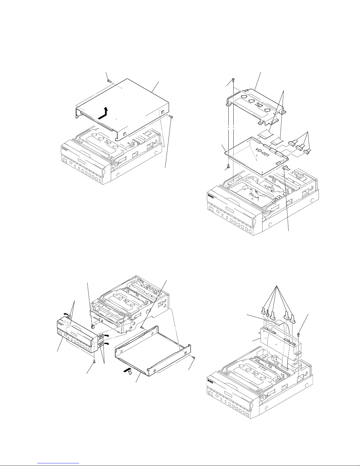
2-1
Note: Follow the disassembly procedure in the numerical order given.
2-1. UPPER CASE 2-3. VD-031 BOARD
2-2. FRONT PANEL ASSEMBLY 2-4. DC/DC CONVERTER UNIT
SECTION 2
DISASSEMBLY
DSR-11
2 Two screws
3 Upper case
1 Two screws
4 Two screws
(PTT2.6 × 5)
6 Five screws
(PTT2.6 × 5)
7 VD bracket
5 VD-031 board
3 Two flat cables
(CN002, 003)
1 Three connectors
(CN501, 602, 603)
2 Connector
(CN004)
1 Two screws
8 Two slide knobs
6 Two claws
5 Two claws
2 Two screws
3 Upper case
4 Two screws
(PTT2.6 × 5)
7 Front panel
assembly
2 Five connectors
(CN1-5)
3 Two screws
(PTT2.6 × 5)
1 Flat cable
(CN003)
4 DC/DC converter
unit
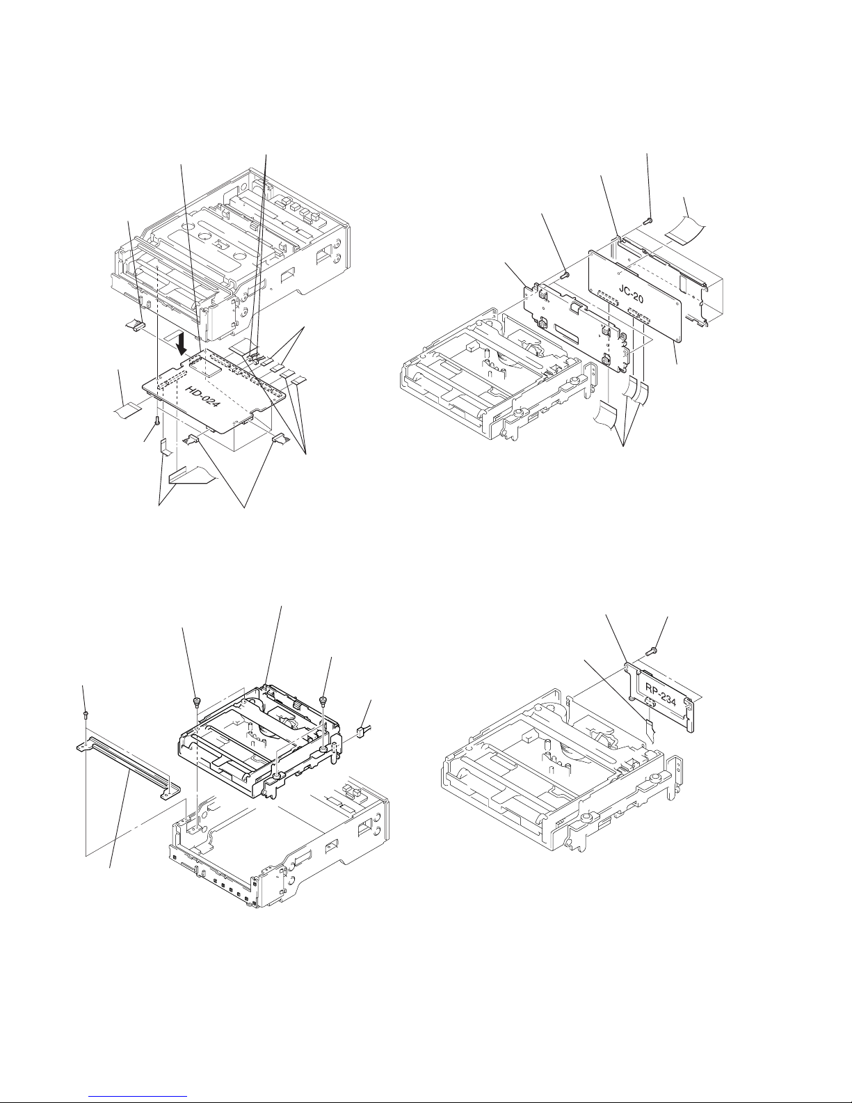
2-2
2-6. MECHANISM DECK 2-8. RP-234 BOARD
2-7. JC-20 BOARD2-5. HD-024 BOARD
2 Front stay
1 Two screws
(PTT2.6 × 5)
3 Two step screws
(M3)
4 Two step screws
(M3)
6 Connector
(CN4400)
5 Mechanism deck
2 Two screws
(T2 × 4.5)
3 RP-234 board
1 Flexible board
(CN101)
8 Four screws
(T2 × 4.5)
3 Two flat cables
(CN703, 705)
2 Flat cable
(CN602)
5 Three flat cables
(CN001, 200, 201)
6 Two flexible boards
(CN400, 500 )
4 Two connectors
(CN601, 704)
7 Two connectors
(CN300, 501)
1 Connector
(CN100)
9 HD-024 board
4 Four screws
(T2 × 4.5)
3 Two screws
(B2 × 4)
5 JC shield case
6 JC shield case
7 JC-20 board
1 Flat cable
(CN5005)
2 Three flat cables
(CN4401, 4402, 6001)
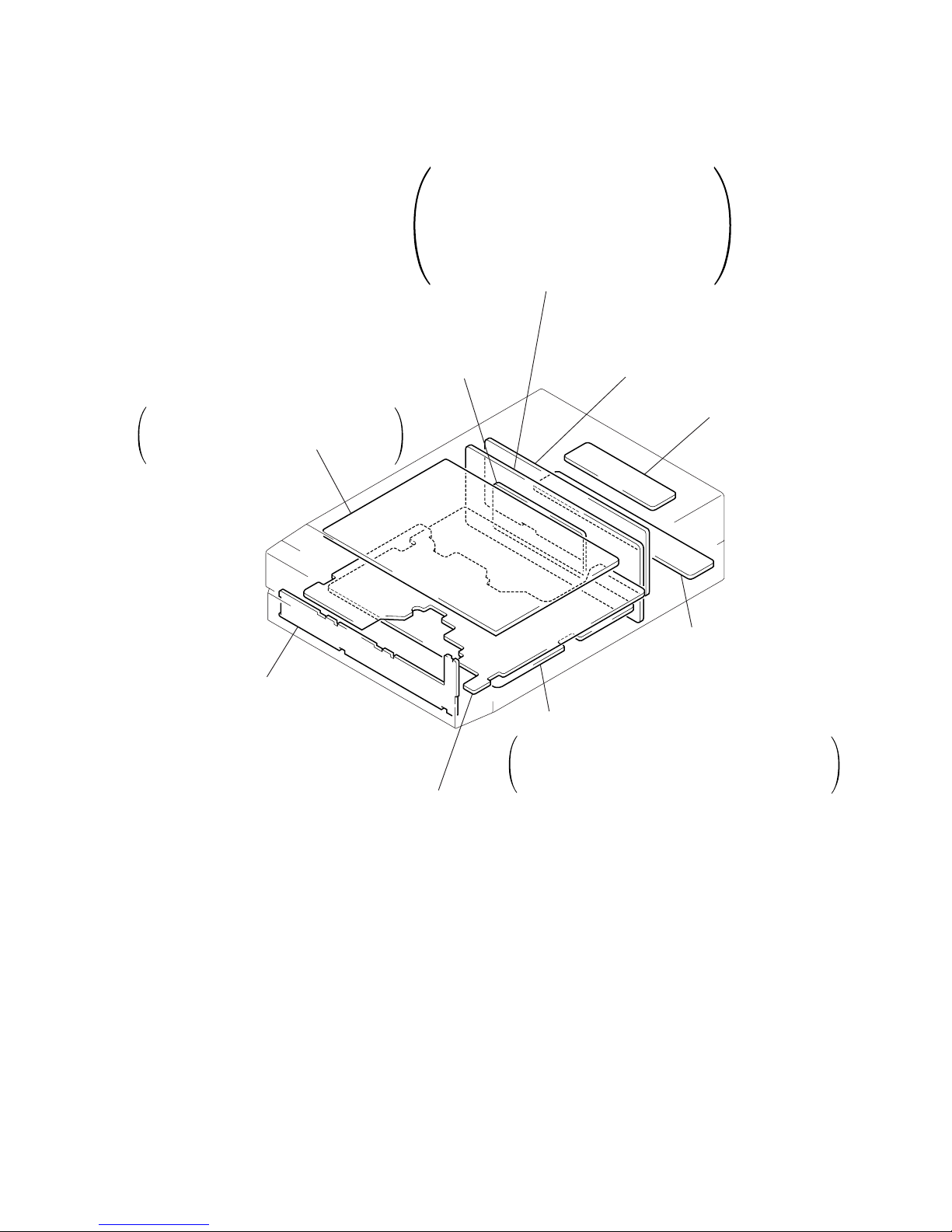
2-3
2-9. CIRCUIT BOARDS LOCATION
2-3 E
JC-20
VIDEO A/D CONVERTER,
CHROMA MIX, AFC, VIDEO DISP,
D/A CONVERTER, SFD, TFD,
DV INTERFACE, AUDIO,
MECHANISM CONTROL,
MODE CONTROL, POWER SUPPLY
RP-234
(REC/PB AMP)
DC-1492
(DC/DC CONVERTER)
JD-002
DV CONVERTER,
CONTROL JACK
JA-006
(AV IN/OUT, DC IN)
MD-76
(TAPE SENSOR)
FR-175
(USER CONTROL)
VD-031
INTERF A CE, VIDEO DECODER,
VIDEO OUTPUT, AUDIO,
Y/C SEPARATION
(
(
HD-024
HI CONTROL, MATRIX KEY CONTROL,
LED DRIVE, DC/DC CONVERTER,
MOTOR DRIVE
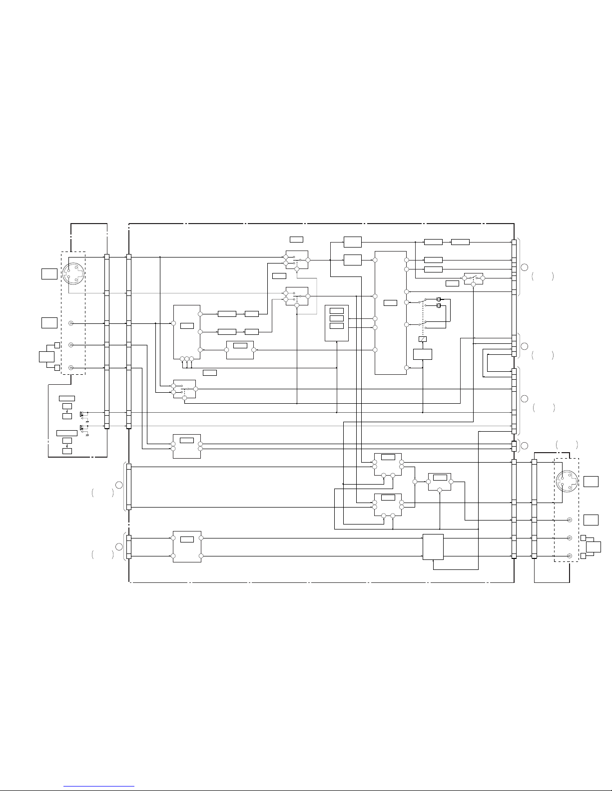
DSR-11
IC700
OSC
(SEE PAGE 4-59)
IC107
S-Y/V
SWITCH
(SEE PAGE 4-53)
IC701
Y/C
SEP.
(SEE PAGE 4-59)
IC110
IC101
IC100
SYNC SEP.
(SEE PAGE 4-54)
4 1
IC304
Y OUT
DRIVER
(SEE PAGE4-56)
IC502
NTSC/PAL
NTSC
PAL
AUDIO INPUT
AMP
5 7
3 1
IC501
AUDIO OUTPUT
AMP
(SEE PAGE 4-57)
3 1
5 7
2
4
13
16
6 14
IC300
VIDEO OUT
DRIVER
14
2 13
IC301
C OUT
DRIVER
(SEE PAGE 4-56)
2
4
13
16
6 14
(SEE PAGE 4-58)
(SEE PAGE 4-56)
IC106
C DECODE
(SEE PAGE 4-54)
IC002
(SEE PAGE 4-51)
25
5
28
24
18
20
19
11
10
17
Q119
BUFFER
Q117
BUFFER
FL104
FL103
FL105
DL101
7
3
1
2
IC102
S-Y/Y SWITCH
7
3
1
2
(SEE PAGE 4-53)
IC103
S-C/C SWITCH
(SEE PAGE 4-53)
7
3
1
2
12
X101
14.31818MHz
X102
17.734475MHz
–1
–2
RELAY
DRIVE
Q114, 123,
129, 130
RY101
11
69 70 74
39
31
25
FL102 B. P. F
B. P. FFL101
+
Q500 – 502,
504
MUTING
CN101
(2/2)
R
L
S VIDEO
OUTPUT
VIDEO
OUTPUT
AUDIO
OUTPUT
10
8
14
6
4
5
3
2
12
5
7
16
20
6
8
12
7
3
17
15
11
J101 (2/2)
3
4
1
6
7
5
CN002 (1/2)
CN004
CN501 (1/2)
CN003 (2/2)
Y IN
CR IN
CB IN
AFC Y
HUE ADJ
S/XV
PB/XEE
VD FROM HI
VD TO HI
VD TO HI
VD FROM HI
UVIC Y
NT/XPAL
AUTO REPEAT
XVA MUTE
A REC L
A REC R
Y OUT
C OUT
V OUT
A. L OUT
A. R OUT
Y OUT
C OUT
V OUT
A. L OUT
A. R OUT
R
L
S VIDEO
INPUT
VIDEO
INPUT
AUDIO
INPUT
J101 (1/2)
CN101
(1/2)
S101
AUTO REPEAT
ON
OFF
S102
16
18
3
1
13
9
5
1
20
21
19
10
14
18
22
3
2
4
C IN
V IN
A. L IN
A. R IN
NT/XPAL
AUTO
REPEAT
Y IN
MONITOR C
MONITOR Y
CN002 (2/2)
CN003 (1/2)
CN501 (2/2)
A PB R
A PB L
JA-006 BOARD
(1/2)
(SEE PAGE 4-85)
VD-031 BOARD
JA-006 BOARD
(2/2)
(SEE PAGE 4-85)
A
JC-20 BOARD (1/2)
CN1101 (1/3)
OVERALL 2
SEE PAGE 3-3
B
JC-20 BOARD (2/2)
CN1101 (3/3)
OVERALL 3
SEE PAGE 3-5
D
JC-20 BOARD (1/2)
CN7001 (1/2)
C
HD-024 BOARD (2/2)
CN704
OVERALL 4
SEE PAGE 3-7
OVERALL 2
SEE PAGE 3-3
E
JC-20 BOARD (1/2)
CN1101 (2/3)
OVERALL 2
SEE PAGE 3-4
F
JC-20 BOARD (1/2)
CN7001 (2/2)
OVERALL 2
SEE PAGE 3-4
05
21
4
Y
C
Y
C
SECTION 3
BLOCK DIAGRAMS
3-1 3-2
3-1. OVERALL BLOCK DIAGRAM 1
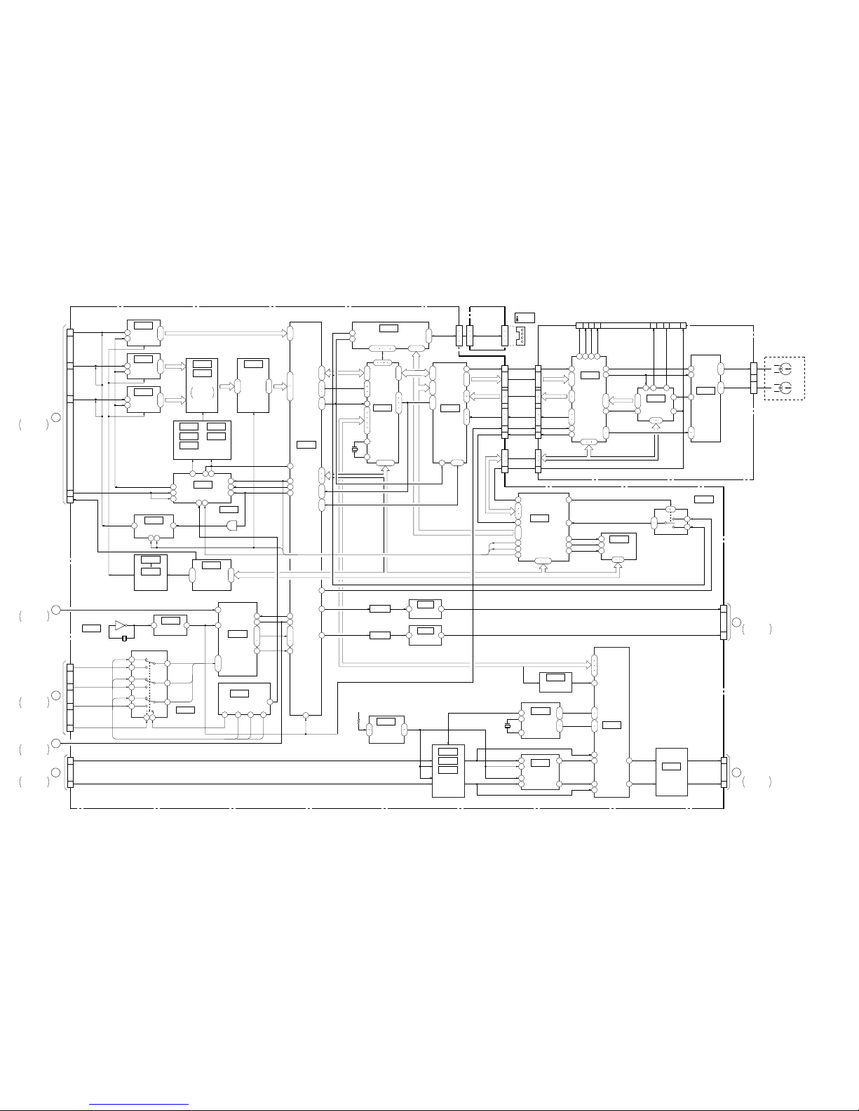
DSR-11
3-3 3-4
3-2. OVERALL BLOCK DIAGRAM 2
5 2
IC1108
1
ı
3
19
ı
21
2
ı
9
18
ı
11
1
ı
8
17
ı
8
90
ı
83
53
ı
61
71
ı
80
5
ı
12
JC-20 BOARD (1/2)
43
24
52 60
3 11
8
4
11
11 45 46 44
96
23 41
7
3
22
55
28
104
105
21
12
A/D
CONVERTER
(SEE PAGE 4-22)
IC2214
IC2209
IC2208
IC2211
1 5
IC1101
IC5002
IC1107
IC2202
IC2203
IC2204
IC2212
IC2210 IC2213
CHROMA
MIX
SEE PAGE
4-23, 24
IC2215
BUFFER
(SEE PAGE 4-24)
IC3300
VFD
(SEE PAGE 4-27)
IC4400
SFD
IC4401
TFD
IC301
TRX
(SEE PAGE 4-12)
IC201
TRF
(SEE PAGE 4-13)
IC101
TRW
IC4402
LIP
(SEE PAGE 4-33)
IC1109
1
ı
8
21
12
A/D
CONVERTER
(SEE PAGE 4-22)
IC1110
1
ı
8
21
12
A/D
CONVERTER
(SEE PAGE 4-22)
TIMING GEN.
(SEE PAGE 4-23, 24)
CLOCK GENERATOR
(SEE PAGE 4-26)
REF DC
GEN.
(SEE PAGE 4-21)
D/A
CONVERTER
(SEE PAGE 4-36)
IC3303
CHARACTER
GENERATOR
(SEE PAGE 4-28)
XSYS RST
IC3302
IC3301
IC6003
SWITCH
(SEE PAGE 4-40)
IC6001
MODE CONTROL
(SEE PAGE 4-40)
18
ı
16
14
35
26
ı
28
33
4
2
3
7
5
6
9
11
10
1 15
1
2
3
(1/2)
BUFFER
(SEE PAGE 4-28
7
ı
4
109
ı
106
100
101
201936
37
82
81
80
82
81
80
21
22
20
32
31
21
96
97
26
41
61
14
14
13
61
99
12
47
84 – 86
111
ı
114
115
116
117
22
23
FL1101
IC1112
BUFFER
(SEE PAGE 4-20)
3 4
68
FL1102
A. +5V
IC1111
BUFFER
(SEE PAGE 4-20)
3 4
50
TBUS 0 – 7
50 52 39 49 40
5 6 7 8 9
37 – 27
9
ı
6
99
100
17
18
44
45
36
37
39
95
ı
100
38
ı
48
15
ı
19
26
ı
22
6
ı
1
15
ı
20
X4400
24.576MHz
MS BUSMS BUS
VSP SI, VSP SO, XVSP SCK
31 32
23
24
30
29
19
18
34
37
6
5
3
2
6
5
3
2
1
2
3
4
6
14
1
4
12
ı
8
17
16
20
19
6
14
1
4
12
ı
8
17
16
20
19
6
10
9
8
6
10
9
8
63
65
64
51
118
95
8
91
90 7
89
111
112
6
88 1
60
78
79
80
26
ı
37
74 75 76
2 3 4
IC5003
MECHANISM
CONTROL
(SEE PAGE 4-37)
IC5006
EEPROM
(SEE PAGE 4-38)
(1/2)
MS BUS
JD-002 (1/2)
BOARD
CN4400
CN253
DV
IN/OUT
CN252
27 13
46
11
7
40
42
45 44 43
345 41
13 31
42 27
21
23
25
17
19
26
28
30
29
47 50 51
22 24
7
6
2
1
12 3 17 8 12 6
RP-234 BOARD
CN1101 (2/3)
15
13
E
VD-031 BOARD
CN002 (2/2)
3
2
A
VD-031 BOARD
CN002 (1/2)
G
HD-024 BOARD (2/2)
CN703 (1/2)
1
JC-20 BOARD
(2/2)
CN1101 (1/3)
Y IN
CR IN
CB IN
AFC Y
HUE ADJ
CN6001 (1/2)
X3300
13.5MHz
OSD SO HI
OSD SCK HI
XCS OSD HI
OSD SW
OSD VD
05
CR (8)
Y (8)
VBUS
0 – 7
CB (8)
CR/CB
(8)
CR/CB
(8)
VRT, VRB
MONITOR Y
MONITOR C
M045
M046
M044
M045
M046
M044
6
5
CN101
M901 (1/2)
DRUM HEAD
YODD, XODD
YEVEN, XEVEN
MSI, XSCK
ADDT0 – 5
CN201
JIG PIN
(FOR CHECK)
CN202CN4402
CN203CN4401
TMS
TCK
TDI
TDO
RF MONITOR
RF IN
JSWP
TXDT0 – 4
XTDT0,
XTDT1
TXDT0 – 4
XTDT0,
XTDT1
CRCKCRCK CRCK
TXDT0 – 4
CLK135
ATF
CLK135
ATF
CLK135
ATF
SWP
XTDT0, 1
HPCK,
XTSY,
TXST
HPCK,
XTSY,
TXST
HPCK, XTSY,
TXST
NTPB,
TPB,
NTPA,
TPA
MSI, MSO, XSCK
DRP SI,
DRPSO,
MSCK
CLAMP
(SEE PAGE 4-25)
(SEE PAGE 4-25)
(SEE PAGE 4-28)
LVD
PB/XREC
WEVN
SOA,
SIC,
SFD, SCK,
SFD, LRCK,
SF BCK
(SEE PAGE 4-32)
(SEE PAGE 4-29)
(SEE PAGE 4-88)
(SEE PAGE 4-14)
OVERALL 1
SEE PAGE 3-2
OVERALL 4
SEE PAGE 3-7
OVERALL 3
SEE PAGE 3-5
2
JC-20 BOARD
(2/2)
OVERALL 3
SEE PAGE 3-5
OVERALL 1
SEE PAGE 3-1
LVD
PB/XREC
WEVN
VSP SI, VSP SO, XVSP SCK
IC7008
INVERTER
(SEE PAGE 4-42)
IC5007
(SEE PAGE 4-35)
5
7
CN7001 (1/2)
CN7001
(2/2)
A. REC L
A. REC R
D
VD-031 BOARD
CN501 (1/2)
OVERALL 1
SEE PAGE 3-2
1
3
F
VD-031 BOARD
CN501 (2/2)
OVERALL 1
SEE PAGE 3-1
IC7001
IC7002
IC7004
AMP,
EMPHANSIS
SWITCH
(SEE PAGE 4-41)
IC7005
AMP
(SEE PAGE 4-41)
60
7
8
38
36
43
42
X7001
6MHz
IC707
AUDIO DSP
(SEE PAGE 4-44)
26
27
13
SDI
SIC
14
15
11
12
23
24
16
17
IC7006
A/D, D/A
CONVERTER
(SEE PAGE 4-42)
IC7009
L. P. F
(SEE PAGE 4-42)
L
R
A. PB L
A. PB R
SOA, SIC, SFD SCK,
SFD LRCK, SFD BCK
IC7003
REF. VOLTAGE
AMP
(SEE PAGE 4-41)
3
5
1
7
5
6
3
2
7
1
5
3
4
6
51
2
5
1 7
3
6
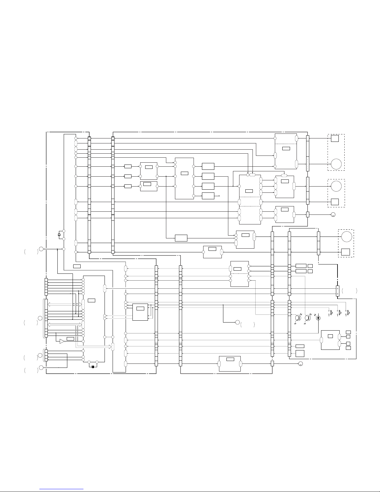
DSR-11
JC-20 BOARD
(2/2)
HD-024 BOARD (1/2)
115
63
36
31
34
33
27
26
30
29
43
44
45
46
15
20
17
18
24
25
21
22
8
7
6
5
46
45
48
47
117
116
49
50
51
52
6.25V
14
15
55 53
5 20
25
22
26
23
27
24
4
1
21
24
6
19
1
63
4
60
42
41
39
40
30
31
32
33
8
12
17
13
9
11
23
22
24
54
17
3
5
7
9
2
23
18
2
1
16
17
14
13
8
7
10
9
11
10
5
6
3
4
1
2
CN5005 (1/2)
CAP FWD, CAP ON
CAP FG
DRUM MASTER CLK
DRUM FWD,
DRUM ON
IC5003
IC500
IC400
IC501
(1/2)
CAPSTAN
MOTOR
DRIVE
CAPSTAN
FG AMP
IC501
(2/2)
C MOTOR
DRIVE
(2/2)
MECHANISM
CONTROL
IC6001
IC6004
(2/2)
MODE
CONTROL
DRUM PG, DRUM FG
CM (+), CM (–)
CM LIMIT ON,
CM LIMIT DET
05
(SEE PAGE 4-70)
(SEE PAGE 4-68)
(SEE PAGE 4-70)
(SEE PAGE 4-70)
C MOTOR
DRIVE
DRUM PG/FG
DRIVE
DRUM
PREDRIVE
CM LIMIT ON, CM LIMIT DET
CM+, CM–
DRUM PG, DRUM FG
DRUM CLK
CAPSTAN
REEL
DRUM
DRUM FWD, DRUM ON
CAP FG
CAP FWD, CAP ON
CN001 (1/2)
(SEE PAGE 4-37)
(SEE PAGE 4-40)
(SEE PAGE 4-40)
DRUM MOTOR
DRIVE
MM
DRUM
PG
CAP
FG
DRUM
MOTOR
CAPSTAN
MOTOR
M905
FL MOTOR
CN400
CN500
CN501
M904
M903
M901 (2/2)
68
69
71
9
28
35
40
50
23
16
11
1
8
6
7
Q103
SWICHING
Q100
SWICHING
Q102
SWICHING
Q101
SWICHING
16
7
9
25
6
7
30
44
39
46
40
IC300
IC100
DC CONTROL
HI C/R SW
REEL PWM
CAP PWM
DRUM PWM
L. P. F.
L. P. F.
L. P. F.
L. P. F.
L. P. F.
(1/3)
IC500
(SEE PAGE 4-70)
(SEE PAGE 4-68)
(SEE PAGE 4-67)
IC200
REEL
MOTOR
DRIVE
(SEE PAGE 4-69)
IC202
REEL FG AMP
(SEE PAGE 4-69)
44
43
41
39
38
119
26
6
1
4
10
12
13
21
22
23
Q200
BUFFER
2
3
REEL
FG
1
ı
6
8
10
REEL
MOTOR
REEL FWD,
REEL ON
REEL M FG
REEL FWD, REEL ON
REEL M FG
CN3
V, U, W
U, V, W
PG, FG
CM LOAD, CM UNLOAD
U, V, W
FG2, FG1
FG1, FG2
REEL V/U/W
MR FG1, MR FG2
15
25
24
2
29
1
2
LM (+), LM (–)LM (+), LM (–)
IC300
(3/3)
LOADING MOTOR
DRIVER
(SEE PAGE 4-68)
LM+, LM– LM+, LM–
MM
M902
CAM MOTOR
CN300
MD-76 BOARD
IC300
(SEE PAGE 4-68)
(2/3)
REEL FG AMP
TAPE TOP/END
DETECT
113
114
7
8
13
14
6
12
10
11
18
19
53
54
20
23
14
17
13
16
19
22
85
96
55
97
22
18
68
98
99
17
16
42
ı
39
4
ı
1
20
IC5008
LEVEL SHIFT
(SEE PAGE 4-38)
71
72
73
22
23
24
44
43
38
37
45
39
41
40
33
32
29
28
27
47
ı
50
34
35
13
21
15
14
1
18
17
16
13
21
15
14
18
17
16
7
ı
4
15
12
14
3
2
8
9
1
7
ı
4
15
12
14
3
2
8
9
IC5
IC4
S REEL FG
T REEL FG
1
7
2
3
6
7
ELETEN
ERROR AMP
(SEE PAGE 4-117)
IC1
IC2
IC3
H
H
MODE
SW
DEW
CN5005 (2/2) CN001 (2/2)
SREEL FG, TREEL FG
TAPE ON
TAPE END
CHIME SCK, CHIME SDA,
CHIME VDD
REC PROOF
S REEL ERR,
T REEL ERR
MODE SW D-A
DW DET
TAPE LED ON
L CASSETTE
SREEL FG,
TREEL FG
TAPE TOP
TAPE END
CHIME SCK,
CHIME SDA,
CHIME VDD
REC PROOF
S ELTN ERR,
T ELTN ERR
MODE SW D-A
DEW DET
TAPE LED ON
L CASSETTE
XC IN
XCC DOWN
S REEL FG, T REEL FG
TAPE TOP
TAPE END
CHIME SCK, CHIME SDA, CHIME VDD
REC PROOF
DEW
MODE D-A
TAPE LED
L CASSETTE
C IN
CC DOWN
REEL ERROR
CN201
CN1
SFG IN
TFG IN
TOP SENS
CN200 CN2
END SENS
S ELETEN, T ELETEN
MODE D-A
DEW
TAPE LED
L CASSETTE
C IN
XC IN
CC DOWN
MODE D-A
DEW
TAPE LED
L CASSETTE
C IN
CC DOWN
S REEL FG
T REEL FG
TAPE TOP
REC PROOF
TAPE END
S ELETEN
T ELETEN
CHIME2 (SCK)
CHIME3 (SDA)
CHIME4 (VDD)
Q2
(TAPE TOP)
Q1
(TAPE END)
FOR CASSETTE
MEMORY
D1
(TAPE LED)
S1
(L/S CASSETTE)
S2
(C IN)
S3
(CC DOWN)
1
2
7
X5001
20MHz
XSYS RST
1
2
21
17
27
30
61
38
58
65
67
72
22
64
62
9
34
33
35
32
50
49
48
81
82
83
40 41
X6001
20MHz
15
17
3
1
5
28
29
19
22
14
4
2
3
23
24
16
18
20
10
8
6
12
CN6002
CN6001 (2/2)
LANC IN
LANC OUT
XLANC PWR ON
EJECT
PARSLEY MODE
XRESET
XSLEEP
XIC RST
MO XWAKEUP
XSYS RST
XCS UVIC
UVIC BUSY
VD FROM HI
VD TO HI
S/XV
PB/XEE
OSD VD
JC-20 BOARD
(1/2)
VD-31 BOARD
CN002 (1/2)
HD-024 BOARD
(2/2)
CN703 (2/2)
UVIC SWIN
MO SCK, MO SO, MO SI
HI SI, HI SO,
HI SCK, XCS MO
CN1101 (3/3)
JIG PIN
(FOR CHECK)
H
B
1
104
105
48
49
3
2
1
ı
6
9
12
1
ı
6
9
12
OVERALL 4
SEE PAGE 3-8
OVERALL 1
SEE PAGE 3-2
OVERALL 2
SEE PAGE 3-3
JC-20 BOARD
(1/2)
2
OVERALL 2
SEE PAGE 3-3
HD-024 BOARD
(2/2)
3
OVERALL 4
SEE PAGE 3-8
27
26
25
26
66
(1/2)
(2/2)
3-5 3-6
3-3. OVERALL BLOCK DIAGRAM 3
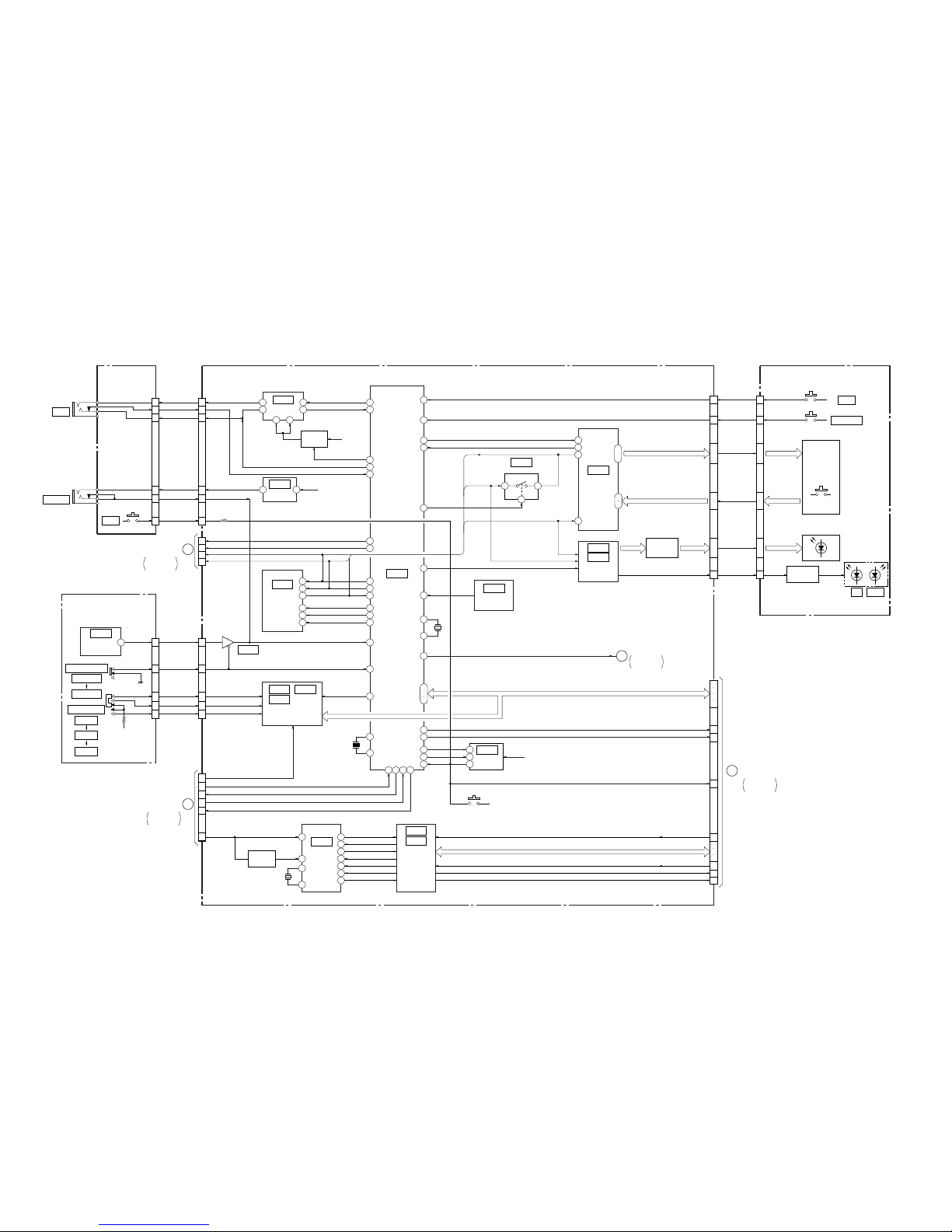
DSR-11
LANC
J201
RESET
S203
CONTROL S
J252
2
17
14
58
100
24
19
65
15
5
6
61
38
32
52
53
1
12
30
21
45
44
46
28
26
4
20
16
40
41
18 78 64 7
8
43
10
14
11
12
10
4 8
IC706
LANC
DRIVER
(SEE PAGE 4-61)
(SEE PAGE 4-63)
Q701
B+ SW
EVER +3V
23
IC602
+5V
REG
(SEE PAGE 4-61)
(SEE PAGE 4-62)
IC705
EEPROM
IC707
HI
CONTROL
IC603
(SEE PAGE 4-63)
IC601
MATRIX KEY
CONTROL
(SEE PAGE 4-63)
IC606
IC605
SERIAL/PARALLEL
CONVERTER
(SEE PAGE 4-63)
IC703
BATT DET
(SEE PAGE 4-61)
(SEE PAGE 4-65)
IC501
REMOTE CONTROL
WIRELESS
CONTROL S
S503
INPUT SELECT
VIDEO
S VIDEO
DV
S504
REMOTE
CONTROL
RECEIVER
IC610
(SEE PAGE 4-64)
(SEE PAGE 4-82)
INST/XVTR4
3
4
2
6
1
7
PARALLEL/SERIAL
CONVERTER
(SEE PAGE 4-64)
IC607
IC608
IC609
1
18 3
10
11
1217
13
28
29
X701
20MHz
31
32
X551
3.579545MHz
IC551
UVIC
CONTROL
(SEE PAGE 4-61)
Q557
SYNC SEP.
IC553
IC552
INVERTER/
AND GATE
(SEE PAGE 4-66)
4
5
2
(RESET)
S701
IC704
REG,RESET
B+
33
34
35
X702
32.768kHz
2 1
4
9
6
8
7
2
3
25
ı
28
Q601 – 609,
Q611
LED DRIVE
KEY MATRIX
S505 – 510
33
10
XEJECT
XPOWER SW
KS1 – 4
KEY1, 2
KS1 – 4
KEY1, 2
REC, PAUSE,
FF, PLAY,
REW, PAL,
NTSC, TAPE,
STREAM, DVCAM
POWER LED
XEJECT
XPOWER SW
POWER LED
XSLEEP
MO XWAKEUP
XIC RST
XSYS RST
XCS UVIC
UVIC BUSY
UVIC SWIN
XC IN
HI SI, HI SO, HI SCK, XCS MO
MO SCK, MO SO, MO SI
34
2
3
5
ı
8
11
ı
20
2
25
1
33
32
30
ı
27
24
ı
15
D513, 514, 516, 519
D525, 527, 529, 532
Q510, 512
LED DRIVE
GREENRED
D510
28
27
29
17
9
8
7
21
23
25
19
15
13
11
1
5
2
3
2
3
6
9
7
1
9
8
5
2
4
10
7
8
9
10
5
28
27
26
25
30
7
6
5
4
3
1
JD-002 BOARD
(2/2)
(SEE PAGE4-88)
FR-175 BOARD (1/2)
HD-024 BOARD (2/2) FR-175 BOARD (2/2)
(SEE PAGE 4-81)
CN201 CN705
CN501
(1/2)
CN602 (1/2)
CN704
CN703 (1/2)
LANC JK IN
LANC JK IN
LANS SIG
SIRCS VCC
XREST XREST
SIRCS DATA
INST/XVTR4
V INPUT SEL
S INPUT SEL
DV INPUT SEL
SIRCS DATA
SIRCS VCC
SIRCS DATA
OSD SW
XCS OSD HI
OSD SO HI
OSD SCK HI
V INPUT SEL
S INPUT SEL
DV INPUT SEL
NT/XPAL
AUTO REPEAT
VD TO HI
VD FROM HI
XVA MUTE
UVIC Y
LANC VCC LANC VCC
SW 3V
G
JC-20 BOARD (1/2)
CN6001 (1/2)
OVERALL 2
SEE PAGE 3-3
C
VD-031 BOARD
CN004
OVERALL 1
SEE PAGE 3-2
UNSW +6V
CN602
(2/2)
CN703 (2/2)
CN501
(2/2)
3
HD-024 BOARD
(1/2)
OVERALL 3
SEE PAGE 3-6
H
JC-20 BOARD (2/2)
CN6001 (2/2)
OVERALL 3
SEE PAGE 3-5
05
EJECT
S501
ON/STANDBY
S502
3-7 3-8
3-4. OVERALL BLOCK DIAGRAM 4

DSR-11
3-9 3-10
3-5. POWER BLOCK DIAGRAM 1
DC IN
J102
F101
F103
F102
2
1
3
2
1
3
UNREG 12V (2)
UNREG 12V (1)
UNREG 12V (3)
GND
CN1CN102
IC301
DC/DC
CONVERTER
(SEE PAGE 4-90)
11
12 5
6
Q302
SWITCHING
Q301
OSC SW
Q402
SWITCHING
Q401
OSC SW
IC401
DC/DC
CONVERTER
(SEE PAGE 4-90)
11
12 5
6
D401
Q702
B–
SWITCHING
Q704 (1/2)
B+
SWITCHING
D302
ZD302
D402
ZD402
ZD702
Q202
SWITCHING
Q201
OSC SW
IC201
DC/DC
CONVERTER
(SEE PAGE 4-90)
11
12 5
6
D202
D102
ZD202
ZD102
Q102
SWITCHING
Q101
OSC SW
IC101
DC/DC
CONVERTER
(SEE PAGE 4-90)
11
12 5
6
Q704 (2/2)
B+
SWITCHING
Q701
EMERGENCY
DETECT
Q703
B+
SWITCHING
Q706, 707,
Q709
POWER
CONTROL
L302L401
L101
L604
L203
L303
L601
L603
L103
L205
L405
L306
JA-006 BOARD
(SEE PAGE 4-85)
DC-1492 BOARD
1
3
4
5
7
1
2
3
4
6
8
1
3
4
5
6
1
2
A
M906
FAN MOTOR
HD-024BOARD
CN100
POWER 2
SEE PAGE 3-11
B
VD-031 BOARD
CN602
POWER 3
SEE PAGE 3-13
C
HD-024 BOARD
CN601
POWER 2
SEE PAGE 3-11
CN3
CN2
CN4
CN5
3V
5V
UNREG 12V
UNSW 6V
UNSW 3.1V
SW 3.1V
VIDEO –5V
AUDIO –5V
UNSW 6V
UNSW 3V
SW 5V
SW 3V
UNSW 12V
P/CONT
SW 12V
05
4
5
4
5
IC801
REF. VOLTAGE GENERATOR
(SEE PAGE 4-89)
R
K
A
FB301
L202FB201
L102FB101
FB401
L305
L204
L602
L307
L304
L403
L404
Q705, 708
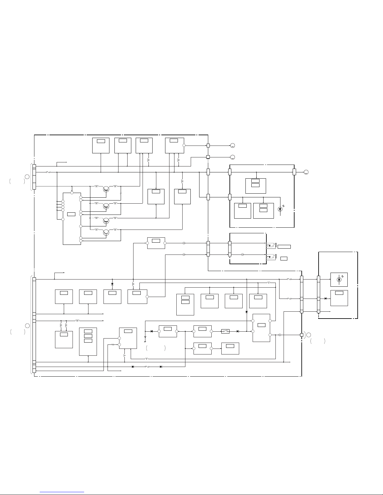
DSR-11
3-11 3-12
3-6. POWER BLOCK DIAGRAM 2
HD-024 BOARD
MD-76 BOARD
IC300
LOADING
MOTOR
DRIVE
(SEE PAGE 4-68)
IC400
CAPSTAN
MOTOR
DRIVE
(SEE PAGE 4-68)
IC500
DRUM/C
MOTOR
DRIVE
(SEE PAGE 4-70)
IC202
REEL FG
AMP
(SEE PAGE 4-69)
IC100
DC
CONTROL
(SEE PAGE 4-67)
IC200
REEL
MOTOR
DRIVE
(SEE PAGE 4-69)
IC1
ELETEN
ERROR AMP
(SEE PAGE 4-117)
IC2
IC3
IC4
IC5
DRUM/C
MOTOR
DRIVER
(SEE PAGE 4-70)
IC501
20
22
24
8
45
46
7
44
13
29
40
39
MM
MM
MM
3
4
1
5
6
A
DC-1492 BOARD
CN3
CN100
5V
3V
UNREG 12V
CAPSTAN
6.25V DC
DRUM
REEL
9
9
18
10
11
10
11
10
11
10
11
M901
DRUM
MOTOR
M903
CAPSTAN
MOTOR
M904
REEL
MOTOR
CN500
SENSOR VCC
CN400
FG VCC
CN201 CN3CN1
MR VCC, HE VCC
CN200 CN2
D1
(TAPE LED)
18
HOLE ELEMENT
(SEE PAGE 117, 118)
T/S REEL FG
(SEE PAGE 117, 118)
POWER 1
SEE PAGE 3-10
JD-002 BOARD
(SEE PAGE 4-88)
FR-175 BOARD
6
110
5
CN705 CN201
CONTROL S
J252
LANC
J201
2 3
IC602
+5V REG
(SEE PAGE 4-63)
IC610
BUFFER
(SEE PAGE 4-64)
IC551
UVIC
CONTROL
(SEE PAGE 4-65)
IC552
INVERTER
(SEE PAGE 4-66)
IC609
IC608
IC607
PARALLEL/
SERIAL
CONVERTER
(SEE PAGE 4-64)
IC707
HI
CONTROL
(SEE PAGE 4-62)
IC553
AND GATE
(SEE PAGE 4-66)
IC706
LANC
DRIVER
(SEE PAGE 4-61)
IC606
IC605
SERIAL/
PARALLEL
CONVERTER
(SEE PAGE 4-63)
IC603
SWITCH
(SEE PAGE 4-63)
IC601
MATRIX KEY
CONTROL
(SEE PAGE 4-63)
IC705
EEPROM
(SEE PAGE4-61)
3
29
2
IC702
+3.6V REG
(SEE PAGE 4-61)
2 3
IC604
+5V REG
(SEE PAGE 4-63)
2 3
IC701
+5V REG
(SEE PAGE 4-61)
IC703
BATT DET
(SEE PAGE 4-61)
IC704
REG, RESET
(SEE PAGE 4-61)
IC501
REMOTE
CONTROL
RECEIVER
(SEE PAGE 4-82)
7
3
6
8
UNSW +6V
UNSW 3V
SW +5V
BATT SENSE UNREG
SW 3V
BT701
BATTERY,
V/L RECHARGEABLE
D701
D608 F601
D603 – 607
F100
D703
D704
D511
F603
F602
SW 3V
D510, 513, 514
D516, 519, 521,
D525, 527, 529
D532, 535
30
4
6
12
11
31
29
23
24
CN501CN602
CN703
UNSW+6V
UNSW 6V
SW 3VSW 3V
BACK UP 3V
D
JC-20 BOARD
CN6001
POWER 4
SEE PAGE 3-15
3
4
5
7
1
2
C
DC-1492 BOARD
CN4
POWER 1
SEE PAGE 3-10
CN601
UNSW 6V
UNSW 3V
SW 5V
SW 3V
UNSW 12V
P/CONT
D551 L705
05
18
+3V
64
L400
L500
L200
Q100
SWITCHING
Q101
SWITCHING
Q103
SWITCHING
Q102
SWITCHING
L100 L104
L101 L105
L103 L107
L102
L552
L706
L551 L553
L106
14
FB201
FB709
FB701
FB601
91
L708
L707
5V
5V
SIRCS VCC
LANC VCC
Q703
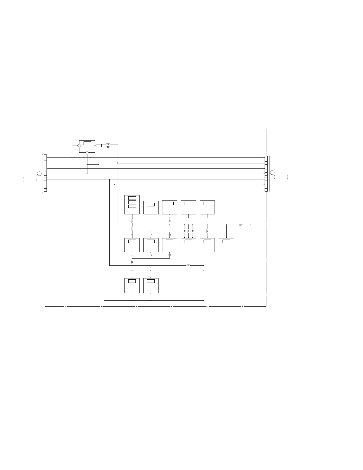
DSR-11
IC001
+5V REG
(SEE PAGE 4-52)
1
6
3
IC110
IC101
IC100
SYNC SEP.
(SEE PAGE 4-54)
IC106
C DECODE
(SEE PAGE 4-54)
IC102
S-Y/Y
SWITCH
(SEE PAGE 4-53)
IC301
C OUT
DRIVER
(SEE PAGE 4-56)
IC103
S-C/C
SWITCH
(SEE PAGE 4-53)
IC107
S-Y/V
SWITCH
(SEE PAGE 4-53)
IC304
Y OUT
DRIVER
(SEE PAGE 4-56)
IC300
VIDEO OUT
DRIVER
(SEE PAGE 4-56)
IC701
Y/C SEP.
(SEE PAGE 4-59)
IC700
OSC
(SEE PAGE 4-59)
IC501
AUDIO
OUTPUT
AMP
(SEE PAGE 4-57)
IC502
AUDIO
INPUT
AMP
(SEE PAGE 4-58)
L001
L002
2
UNSW 6V
SW 3.1V
VIDEO 5V
VIDEO –5V
AUDIO –5V
AUDIO 5V
L108
L300
L302
FB300
FB303
FB304 FB305
L105
L701 L708 L702
IC002
SWITCH
(SEE PAGE 4-51)
L707
L102, 103, 109,
111, 710
L110, 112
FB302
FB301
VD-031 BOARD
05
6
4
3
8
1
2
CN602 CN603
B
DC-1492 BOARD
CN2
POWER 1
SEE PAGE 3-10
UNSW 6V
UNSW 3.1V
SW 3.1V
VIDEO –5V
AUDIO –5V
E
3
1
9
7
6
4
2
JC-20 BOARD
CN1100
POWER 4
SEE PAGE 3-15
VIDEO 5V
UNSW 6V
AUDIO –5V
AUDIO 5V
VIDEO –5V
SW 3.1V
UNSW 3.1V
3-13 3-14
3-7. POWER BLOCK DIAGRAM 3
 Loading...