

Page 1
5-006-640-11(1)
FM/AM
Bluetooth® Car Audio
Owner’s Record
The model and serial numbers are locat
bottom of the unit.
Record these numbers in the spaces provided below.
Refer to these numbers whenever you call upon your
Sony dealer regarding this product.
Model No. DSX-GS80
Serial No.
ed on the
Operating Instructions
Mode d’emploi
GB
FR
To cancel the demonstration (DEMO) display,
see page 8.
For the connection/installation, see page 13.
Pour annuler l’affichage de démonstration
(DEMO), reportez-vous à la page XX.
Pour le raccordement/l’installation, reportez-vous à
la page XX.
DSX-GS80
Page 2
For safety, be sure to install this unit in
the dashboard of the car as the left side
of the unit becomes hot during use.
For details, see “Connection/
Installation” (page 13).
The nameplate indicating operating voltage,
etc., is located on the bottom of the chassis.
The validity of the CE marking is restricted to
only those countries where it is legally
enforced, mainly in the countries EEA
(European Economic Area) and Switzerland.
Warning
FOR THE CUSTOMERS IN THE USA.
NOT APPLICABLE IN CANADA,
INCLUDING IN THE PROVINCE OF
QUEBEC.
POUR LES CLIENTS AUX ÉTATS-UNIS.
NON APPLICABLE AU CANADA, Y
COMPRIS LA PROVINCE DE QUÉBEC.
This equipment has been tested and
found to comply with the limits for a Class
B digital device, pursuant to Part 15 of the
FCC Rules.
These limits are designed to provide
reasonable protection against harmful
interference in a residential installation.
This equipment generates, uses, and can
radiate radio frequency energy and, if not
installed and used in accordance with the
instructions, may cause harmful
interference to radio communications.
However, there is no guarantee that
interference will not occur in a particular
installation. If this equipment does cause
harmful interference to radio or television
reception, which can be determined by
turning the equipment off and on, the
user is encouraged to try to correct the
interference by one or more of the
following measures:
– Reorient or relocate the receiving
antenna.
– Increase the separation between the
equipment and receiver.
– Connect the equipment into an outlet
on a circuit different from that to which
the receiver is connected.
– Consult the dealer or an experienced
radio/TV technician for help.
You are cautioned that any changes or
modifications not expressly approved in
this manual could void your authority to
operate this equipment.
2GB
Page 3
This device complies with part 15 of FCC
Rules and Innovation, Science and Economic
Development Canada’s licence-exempt
RSS(s). Operation is subject to the following
two conditions:
(1) this device may not cause harmful
interference, and
(2) this device must accept any interference
received, including interference that may
cause undesired operation.
This transmitter must not be co-located or
operated in conjunction with any other
antenna or
This equipment complies with FCC/ISED
radiation exposure limits set forth for an
uncontrolled environment and meets the
FCC radio frequency (RF) Exposure
Guidelines and RSS-102 of the ISED radio
frequency (RF) Exposure rules as this
equipment has very low levels of RF energy.
transmitter.
If you have any questions about this
product:
Visit: https://www.sony.com/electronics/
support
Contact: Sony Customer Information Service
Center at 1-800-222-7669
Write: Sony Customer Information Service
Center 12451 Gateway Blvd., Fort Myers, FL
33913
Supplier’s Declaration of Conformity
Trade Name: SONY
Model: DSX-GS80
Responsible Party: Sony Electronics Inc.
Address: 16535 Via Esprillo, San Diego, CA
92127 U.S.A.
Telephone Number: 858-942-2230
This device complies with part 15 of the FCC
rules. Operation is subject to the following
two conditions:
(1) This device may not cause harmful
interference, and
(2) this device must accept any interference
received, including interference that may
cause undesired operation.
For the State of California, USA only
Perchlorate Material – special handling may
See
apply,
www.dtsc.ca.gov/hazardouswaste/
perchlorate
WARNING: Do not ingest
battery, Chemical Burn Hazard.
The remote commander contains a
coin/button cell battery. If the coin/button
cell battery is swallowed, it can cause severe
internal burns in just 2 hours and can lead to
death.
Keep new and used batteries away from
children. If the battery compartment does
not close securely, stop using the product
and keep it away from children.
If you think batteries might have been
swallowed or placed inside any part of the
body, seek immediate medical attention.
Note on the lithium battery
Do not expose the battery to excessive heat
such as direct sunlight, fire or the like.
Warning if your car’s ignition has no
ACC position
Be sure to set the AUTO OFF function.
The unit will shut off
automatically in the set time after the
unit is turned off and the clock is
displayed (i.e. press and hold OFF for 1
second), which prevents battery drain. If
you do not set the AUTO OFF function,
press and hold OFF until the display
disappears each time you turn the
ignition off.
completely and
3GB
Page 4
Disclaimer regarding services offered
by third parties
Services offered by third parties may be
changed, suspended, or terminated without
prior notice. Sony does not bear any
responsibility in these sorts of situations.
Important notice
Caution
IN NO EVENT SHALL SONY BE LIABLE FOR
ANY INCIDENTAL, INDIRECT OR
CONSEQUENTIAL DAMAGES OR OTHER
DAMAGES INCLUDING, WITHOUT
LIMITATION, LOSS OF PROFITS, LOSS OF
REVENUE, LOSS OF DATA, LOSS OF USE OF
THE PRODUCT OR ANY ASSOCIATED
EQUIPMENT, DOWNTIME, AND PURCHASE R’S
ME RELATED TO OR ARISING OUT OF THE
TI
USE OF THIS PRODUCT, ITS HARDWARE
AND/OR ITS SOFTWARE.
Dear customer, this product includes a radio
transmitter.
Please check your vehicle operation manual
or contact the manufacturer of your vehicle
or your vehicle dealer, before you install this
product into your vehicle.
Emergency calls
This BLUETOOTH car handsfree and the
electronic device connected to the
handsfree operate using radio signals,
cellular, and landline networks as well as
user-programmed function, which cannot
guarantee connection under all conditions.
Therefore do not rely solely upon any
electronic device for essential
communications (such as medical
emergencies).
On BLUETOOTH communication
Microwaves emitting from a BLUETOOTH
device may affect the operation of
electronic medical devices. Turn off this
unit and other BLUETOOTH devices in the
following locations, as it may cause an
accident.
– where inflammable gas is present, in a
hospital, train, airplane, or petrol station
– near automatic doors or a fire alarm
This unit supports security capabilities that
comply with the BLUETOOTH standard to
provide a secure connection when the
BLUETOOTH wireless technology is used,
but security may not be enough
depending on the setting. Be careful when
communicating using BLUETOOTH wirel ess
technology.
We do not take any responsibility for the
leakage of information during BLUETOOTH
communication.
If you have any questions or problems
concerning your unit that are not covered in
this manual, consult your nearest Sony
dealer.
4GB
Page 5
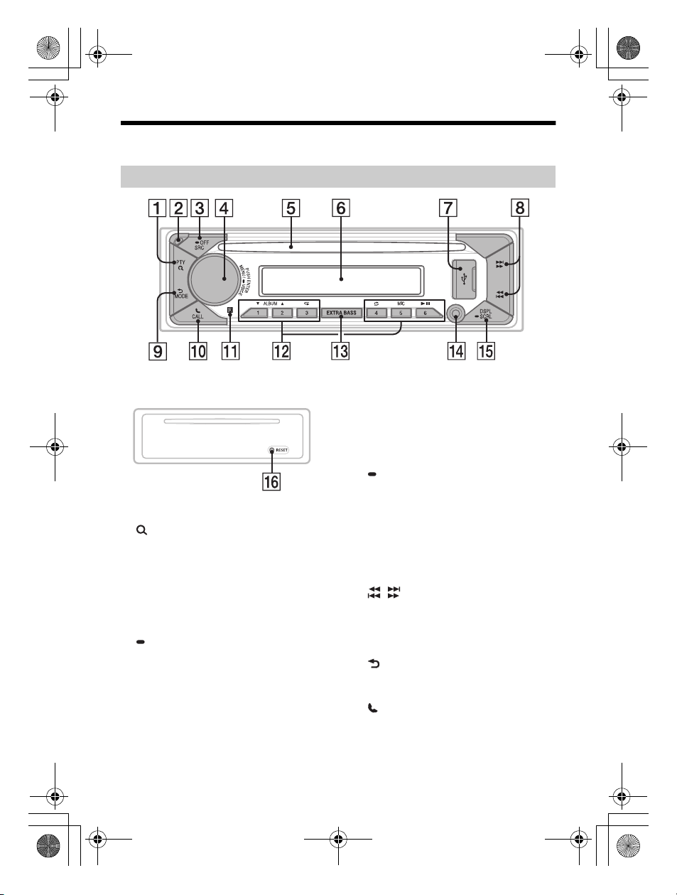
Guide to Parts and Controls
Main unit
Front panel removed (inner panel)
PTY (program type)
Select PTY in RDS.
(browse)
Enter the browse mode during playback.
(Not available when a USB device in
AndroidTM mode or iPod is connected.)
Front panel release button
SRC (source)
Turn on t he po wer.
Change the source.
OFF
Press and hold for 1 second to turn the
source off and display the clock.
Press and hold for more than 2 seconds
to turn off the power and the display.
If the unit is turned off and the display
disappears, operation by the remote
commander is not available.
Control dial
Rotate to adjust the volume.
PUSH ENTER
Enter the selected item.
Press SRC, rotate then press to change
the source (timeout in 2 seconds).
MENU
Open the setup menu.
VOICE
Press and hold for more than 2
seconds to activate voice dial, voice
recognition (Android smartphone
only), or the Siri function (iPhone only).
Disc slot
Display window
USB port
/ (SEEK –/+)
Tune in radio stations automatically.
Press and hold to tune manually.
/ (prev/next)
/ (fast-reverse/fast-forward)
(back)
Return to the previous display.
MODE
CALL
Enter the call menu. Receive/end a call.
Press and hold for more than 2 seconds
to switch the BLUETOOTH signal.
Receptor for the remote commander
5GB
Page 6
Number buttons (1 to 6)
Receive stored radio stations. Press and
hold to store stations.
ALBUM /
Skip an album for audio device. Press and
hold to skip albums continuously.
(Not available when a USB device in
Android mode or iPod is connected.)
Press to thumbs up, or to thumbs
down in Pandora®.
(repeat)
(Not available when a USB device in
Android mode is connected.)
le)
(shuff
(Not available when a USB device in
Android mode is connected.)
MIC
(play/pause)
EXTRA BASS
Reinforces bass sound in synchronization
with the volume level. Press to change
the EXTRA BASS setting: [1], [2], [OFF].
AUX input jack
DSPL (display)
Press to change display items.
SCRL (scroll)
Press and hold to scroll a display item.
RESET (inner panel)
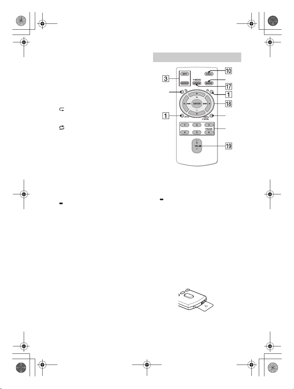
RM-X231 Remote commander
The VOL (volume) + button has a tactile dot.
SOUND
Open the SOUND menu directly.
MENU
Press and hold to open the setup menu.
///
Select a setup item, etc.
ENTER
Enter the selected item.
Press and hold for more than 2 seconds
to establish or terminate the “Sony |
Music Center” function.
/ (prev/next)
+/– (album +/–)
VOL (volume) +/–
6GB
Remove the insulation film before use.
Page 7

Getting Started
Detaching the Front Panel
You can detach the front panel of this unit to
prevent theft.
1 Press and hold OFF until the unit
turns off, press the front panel
release button , then pull the panel
towards you to remove.
Caution alarm
If you turn the ignition switch to the OFF
position without detaching the front panel,
the caution
seconds. The alarm will only sound if the
built-in amplifier is used.
alarm will sound for a few
Attaching the front panel
Resetting the Unit
Before operating the unit for the first time,
or after replacing the car battery or
changing connections, you must reset the
unit.
Press RESET on the inner panel with a ballpoint pen, etc., after detaching the front
panel.
Note
Resetting the unit will erase the clock setting and
some stored contents.
Pairing with a Bluetooth®
Device
When connecting
the first time, mutual registration (called
“pairing”) is required. Pairing enables this
unit and other devices to recognize each
other. This unit can connect two
BLUETOOTH devices (two mobile phones,
or a mobile phone and an audio device).
1 Press MENU, then rotate and press
the control dial to select [BLUETOOTH]
[PAIRING] [DEVICE 1]/[DEVICE 2]*.
flashes while the unit is in pairing
standby
mode.
* [DEVICE 1] or [DEVICE 2] will be changed to
the paired device name after pairing is
complete.
2 Perform pairing on the BLUETOOTH
device so it detects this unit.
3 Select your model name shown in
the
display of the BLUETOOTH device*.
When pairing is made, stays lit.
* If passkey input is required on the
BLUETOOTH
a BLUETOOTH device for
device, input [0000].
GB
7
Page 8

Canceling the Demonstration
Mode
You can cancel the demonstration display
which
appears when the source is off and the
clock is displayed.
1 Press MENU, rotate the control dial to
select [GENERAL], then press it.
2 Rotate the control dial to select [DEMO],
then press it.
3 Rotate the control dial to select
[DEMO-OFF], then press it.
ng is complete.
The setti
4 Press (back) twice.
The display returns to normal reception/
play mode.
Updating the Firmware
To update the firmware, visit the support site on
th
e back cover, then follow the online
instructions.
Notes
Using a USB device (not supplied) is required for
updating the firmware. Store the updater in the USB
device, and connect the device to the USB port, then
perform the update operation.
Updating the firmware takes a few minutes to
complete. During the update, do not turn the
ignition to th
device.
e OFF position, nor remove the USB
About Help Guide
For details on the functions and operations that are
not covered in this manual, refer to Help Guide.
http://xxxxxxxxx
GB
8
Page 9

Additional Information
Precautions
• Do not leave the front panel or audio
devices on the dashboard.
• When the unit is turned on, the power
antenna (aerial) extends automatically.
• Do not splash liquid onto the unit.
Playback order of audio files
Folde r (alb um)
Audio file (track)
About iPod
• You can connect to the following iPod
models. Update your iPod devices to the
latest
software before use.
Compatible iPhone/iPod models
Compatible Model Bluetooth® USB
iPhone XR
iPhone Xs max
iPhone Xs
iPhone X
iPhone 8
iPhone 8 Plus
iPhone 7
iPhone 7 Plus
iPhone SE
iPhone 6s
iPhone 6s Plus
iPhone 6
iPhone 6 Plus
iPhone 5s
iPhone 5c
iPhone 5
iPhone 4s
iPod touch
(6th generation)
iPod touch
(5th generation)
iPod nano
(7th generation)
• Use of the Made for Apple badge means
that an accessory has been designed to
connect specifically to the Apple product(s)
identified in the badge, and has been
certified by the developer to meet Apple
performance standards. Apple is not
responsible for the operation of this device
or its compliance with safety and
regulatory standards.
Please note that the use of this accessory
with an Apple product may affect wireless
performance.
If you have any questions or problems
concerning your unit that are not covered in
this manual, consult your nearest Sony
dealer.
GB
9
Page 10

Maintenance
+ side up
Lithium battery (CR202 5)
Specifications
Replacing the lithium battery (CR2025)
of the remote commander
When the battery becomes weak, the range
of the remote commander becomes shorter.
CAUTION
Danger of explosion if battery is incorrectly
replaced. Replace only with the same or
equivalent type.
Note on the lithium battery
Keep the lithium battery out of the
children. Should the battery be swallowed,
immediately consult a doctor.
reach of
Cleaning the connectors
Avoid touching the connectors directly. The
unit may not function properly if the
connectors between the unit and the front
panel are not clean. In order to prevent
this, detach the front panel (page 7) and
clean the connectors with a cotton swab.
Do not apply too much force. Otherwise, the
connectors may be damaged.
Note
For safety, do not remove the front panel while
driving.
FOR THE CUSTOMERS IN THE USA. NOT
APPLICABLE IN CANADA, INCLUDING IN
THE PROVINCE OF QUEBEC.
POUR LES CLIENTS AUX ÉTATS-UNIS.
NON APPLICABLE AU CANADA, Y
COMPRIS LA PROVINCE DE QUÉBEC.
AUDIO POWER SPECIFICATIONS
CTA2006 Standard
Power Output: 45 Watts RMS ×
4 at 4 Ohms < 1% THD+N
SN Ratio: 80 dBA
(reference: 1 Watt into 4 Ohms)
Tuner section
FM
Tuning range: 87.5 MHz – 107.9 MHz
Usable sensitivity: 8 dBf
l-to-noise ratio: 73 dB
Signa
Separation: 50 dB at 1 kHz
AM
Tuning range: 530 kHz – 1,710 kHz
Sensitivity: 26 μV
USB Player section
Interface: US
Maximum current:
Front: 1 A
Rear: 1.5 A
Maximum number of recognizable files
(tracks): 10,000
Compatible Android Open Accessory
protocol (AOA): 2.0
Corresponding codec:
MP3 (.mp3)
Bit rate: 8 kbps – 320 kbps (Supports
Sampling rate: 16 kHz – 48 kHz
WMA (.wma)
Bit rate: 32 kbps – 192 kbps (Supports
Sampling rate: 32 kHz, 44.1 kHz,
AAC (.m4a, .mp4)
Bit rate: 8 kbps – 320 kbps
Sampling rate: 11.025 kHz – 48 kHz
WAV (
Bit depth: 16 bit
Sampling rate: 44.1 kHz, 48 kHz
B (High-speed)
VBR (Variable Bit Rate))
VBR (Variable Bit Rate))
48 kHz
.wav)
10GB
Page 11

FLAC (.flac)
Bit depth: 16 bit, 24 bit
Sampling rate: 44.1 kHz, 48 kHz
Wireless
Communication
Communication System:
BLUETOOTH Standard version 3.0
Output:
BLUETOOTH Standard Power Class 2
(Max. Conducted +1 dBm)
Maximum communication range*
1
:
Line of sight approx. 10 m (33 ft)
Frequency band:
2.4 GHz band
(2.4000 GHz – 2.4835 GHz)
Modulation method: FHSS
Compatible BLUETOOTH Profiles*
2
:
A2DP (Advanced Audio Distribution
Profile) 1.3
AVRCP (Audio Video Remote Control
Profile) 1.5
H
FP (Handsfree Profile) 1.6
PBAP (Phone Book Access Profile)
SPP (Serial Port Profile)
Corresponding codec:
SBC (.sbc), AAC (.m4a)
*1 The actual range will vary depending on factors
such as obstacles between devices, magnetic
fields around a microwave oven, static electricity,
reception sensitivity, antenna (aerial)’s
performance, operating system, software
application, etc.
*2 BLUETOOTH standard profiles indicate the
purpose of BLUETOOTH communication between
devices.
Power amplifier section
Output:
Speaker outputs
Speaker impedance: 2 Ω/4 Ω – 8 Ω
Maximum power output: 100 W × 4 (at 2 Ω/
4 Ω)
General
Power requirements: 12 V DC car battery
(negative ground (earth))
Rated current consumption: 10 A
Dimensions:
Approx. 178 mm × 50 mm × 177 mm
(7 1/8 in × 2 in × 7 in) (w/h/d)
Mounting dimensions:
Approx. 182 mm × 53 mm × 160 mm
(7 1/4 in × 2 1/8 in × 6 3/8 in) (w/h/d) Mass:
Approx. 1.0 kg (2 lb 11 oz)
Package contents:
Main unit (1)
Remote commander (1): RM-X231
Parts for installation and connections
(1 set)
Optional accessories/equipment:
SiriusXM Connect Vehicle Tuner: SXV100,
SXV200,
Cable for steering wheel remote input:
Ask the dealer for detailed information.
Design and specifications are subject to
change without notice.
SXV300
RC-SR1
11
GB
Page 12

Copyrights
sXM Connect Vehicle Tuner and Subscription
Siriu
sold separately.
www.siriusxm.com
Sirius, XM and all related marks and logos are
trademarks of Sirius XM Radio Inc. All rights
reserved.
The Bluetooth® word mark and logos are registered
trademarks owned by the Bluetooth SIG, Inc. and
any use of such marks by Sony Corporation is
under license. Other trademarks and trade names
are those of their respective owners.
Windows Media is either a registered trademark or
trademark of Microsoft Corporation in the United
States and/or other countries.
This product is protected by certain intellectual
property rights of Microsoft Corporation. Use or
distribution of such technology outside of this
product is prohibited without a license from
Microsoft or an authorized Microsoft subsidiary.
Apple, iPhone, iPod, iPod nano, iPod touch, and
Siri are trademarks of Apple Inc., registered in the
U.S. and other countries.
PANDORA, the PANDORA logo, and the Pandora
trade dress are trademarks or registered
trademarks of Pandora Media, LLC. Used with
permission.
Android is a trademark of Google LLC.
libFLAC
Copyright (C) 2000-2009 Josh Coalson
Copyright (C) 2011-2013 Xiph.Org Foundation
Redistribution and use in source and binary forms,
with or without modification, are permitted
provided that the following conditions are met:
– Redistributions of source code must retain the
above copyright notice, this list of conditions and
the following disclaimer.
– Redistributions in binary form must reproduce the
above copyright notice, this list of conditions and
the following disclaimer in the documentation
and/or other materials provided with the
distribution.
– Neither the name of the Xiph.org Foundation nor
the names of its contributors may be used to
endorse or promote products derived from this
software without specific prior written
permission.
THIS SOFTWARE IS PROVIDED BY THE COPYRIGHT
HOLDERS AND CONTRIBUTORS “AS IS” AND ANY
EXPRESS OR IMPLIED WARRANTIES, INCLUDING, BUT
NOT LIMITED TO, THE IMPLIED WARRANTIES OF
MERCHANTABILITY AND FITNESS FOR A PARTICULAR
PURPOSE ARE DISCLAIMED. IN NO EVENT SHALL THE
FOUNDATION OR CONTRIBUTORS BE LIABLE FOR
ANY DIRECT, INDIRECT, INCIDENTAL, SPECIAL,
EXEMPLARY, OR CONSEQUENTIAL DAMAGES
(INCLUDING, BUT NOT LIMITED TO, PROCUREMENT
OF SUBSTITUTE GOODS OR SERVICES; LOSS OF USE,
DATA, OR PROFITS; OR BUSINESS INTERRUPTION)
HOWEVER CAUSED AND ON ANY THEORY OF
LIABILITY, WHETHER IN CONTRACT, STRICT
LIABILITY, OR TORT (INCLUDING NEGLIGENCE OR
OTHERWISE) ARISING IN ANY WAY OUT OF THE USE
OF THIS SOFTWARE, EVEN IF ADVISED OF THE
POSSIBILITY OF SUCH DAMAGE.
12GB
Page 13

Connection/Installation
5 × max. 8 mm
Cautions
•Run all ground (earth) leads to a
common ground (earth) point.
•Do not get the leads trapped under a
screw, or caught in moving parts (e.g., seat
railing).
•Before making connections, turn the car
ignition off to avoid short circuits.
•Connect the yellow and red power supply
leads only after all other leads have been
connected.
•Be sure to insulate any loose unconnected
leads with electrical tape for safety.
• Choose the installation location carefully so
that the unit will not interfere with normal
driving operations.
• Avoid installing the unit in areas s
dust, dirt, excessive vibration, or high
temperature, such as in direct sunlight or
near heater ducts.
• Use only the supplied mounting hardware
for a safe and secure installation.
Note on the power supply lead (yellow)
When connecting this unit in combination with
other stereo components, the amperage rating of
the car circuit to which the unit is connected must
be higher than the sum of each component’s fuse
amperage rating.
Note on installing in cars with a start-stop
system
The unit may restart when starting the engine from
start-stop. In this case, turn off the start-stop system
of your car.
Mounting angle adjustment
Adjust the mounting angle to less than 30°.
ubject to
Parts List for Installation
Mounting sleeve(1)
Trim ring(1)
Power supply leads (1)
Double-sided tape (1)
• This parts list does not include all the
package contents.
• The mounting sleeve and the trim ring
are attached to the unit before shipping.
Before mounting the unit, use the release
keys to remove the mounting sleeve
from the unit. For details, see “Removing
the mounting sleeve”.
• Keep the release keys for future use as
they are also necessary if you remove the
unit from your car.
Release keys (2)
Mounting screws
(7/32 × max. 5/16 in) (4)
Microphone (1)
Flat-mount base (1)
13
GB
Page 14

Connection
White
White/black striped
Gray
Gray/black strip ed
Green
Green/black striped
Purple
Purple/black striped
Red
Blue/white striped
Orange/white striped
Black
Yel lo w
Black
Yel lo w
3
*
3
*
3
*
10
*
When connecting to the battery directly*12*13
Power amplifier*
Satellite radio tuner
(SiriusXM)*
Smartphone*8, iPod/
9
, USB device
iPhone*
Front speaker*1*2*
Rear speaker*1*2*
For details, see “Making
nnections” (page 15).
co
Subwoofer*
1
1
*5*
1
6
1
*
11
11
14GB
from a wi red remote con trol
(not supplied)*
4
from a car antenna (aerial)*
7
Page 15

*1 Not supplied
*2 Speaker impedance: 4 Ω – 8 Ω × 4
*3 RCA pin cord (not supplied)
*4 Depending on the type of car, use an adaptor
for a wired remote control (not supplied). For
details on using the wired remote c
“Using the wired remote control” (page 17).
*5 Whether in use or not, route the microphone
input cord such that it does not interfere with
driving operations. Secure the cord with a
clamp, etc., if it is installed around your feet.
*6 For details on ins
“Installing the microphone” (page 16).
*7 Depending on the type of car, use an adaptor
(not supplied) if the antenna (aerial) connector
does not fit.
*8 To connect a smartphone to the main unit, an
appropriate cable (not supplied) is required.
*9 To connect an iPod/iPhone, use the USB
connection cable for iPod (not supplied).
*10 Ferrite sleeve
*11 Use speakers with 50W RMS or higher power
input capacity. Using Sony XB series full range
speakers is recommended.
*12 When the amperage rating of the fuse used on
your car is 10 A, make the power connection to
the battery directly to avoid short circuits.
*13 Before connection, arranging the yellow and
black leads of the power connector is required.
talling the microphone, see
ontrol, see
Making connections
To the +12 V power terminal which is
energized when the ignition switch is
set to the accessory position
If there is no accessory position, connect
to the +12 V power (battery) terminal
which is energized at all times.
Be sure to first connect the black ground
(earth) lead to a common ground (earth)
point.
To the power antenna (aerial) control
lead or the power supply lead of the
antenna (aerial) booster
It is not necessary to connect this lead if
there is no power antenna (aerial) or
antenna (aerial) booster, or with a
manually-operated telescopic antenna
(aerial).
To AMP REMOTE IN of an optional
power amplifier
This connection is only for amplifiers and
a power antenna (aerial). Connecting any
other system may damage the unit.
To a car’s illumination signal
Be sure to first connect the black ground
(earth) lead to a common ground (earth)
point.
To a common ground (earth) point
First connect the black ground (earth)
lead, then connect the yellow and red
power supply leads.
To the +12 V power terminal which is
energized at all times
Be sure to first connect the black ground
(earth) lead to a common ground (earth)
point.
When connecting to the battery directly
When the amperage rating of the fuse used
on your car is 10 A, make the power
connection to the battery directly to avoid
short circuits.
to a metal point of car
to the positive battery terminal
Notes
• Despite connecting to the power supply lead of
the car, the unit may not fully provide its
performance due to insufficient power. In this
case, make the pow er connection to the battery
directly.
• All power wires connected to the positive battery
post should be fused within 450 mm (18 in) of the
battery post, and before they pass through any
metal.
• Make sure that the car’s battery wires connected
to the car (ground (earth) to chassis)* are of a wire
gauge at least equal to that of the main power
wire connected from the battery to the head unit.
• During full-power operation, a current of more
than 15 A will run through the system. Therefore,
make sure that the wires to be connected to the
+12 V and GND terminals of this unit are at least
14-Gauge (AWG14) or have a sectional area of
more than 2mm² (3/
When making the speaker parallel connection,
use wires with more than 12-Gauge (AWG12) or
wire that have a sectional area of more than 3.5
mm² (5/32 in).
32 in).
Less than 450 mm (18 in)
Fuse (15 A)
+12 V car battery
*
If you have any questions or problems
concerning the connection, consult the
dealer for details.
15GB
Page 16

Subwoofer Easy Connection
You can use a subwoofer without a power
amplifier when it is connected to a rear
speaker lead.
Front speaker
Subwoofer
Note
Use a subwoofer with an impedance of 4 Ω to 8 Ω,
and with adequate power handling capacities to
avoid damage.
Memory hold connection
When the yellow power supply lead is
connected, power will always be supplied to
the memory circuit even when the ignition
switch is turned off.
Speaker connection
• Before connecting the speakers, turn the
unit off.
• Use speake
rs with a 2 Ω impedance or 4 Ω
to 8 Ω impedance, and with adequate
power handling capacities to avoid
damage.
Speaker Parallel Connection
When making the speaker parallel
connection for a
sure to:
– Make the power connection to the battery
directly.
– Set [SPEAKER
Ohm].
high volume playback, be
LOAD] in [GENERAL] to [2
Front speaker
(4 Ω to 8 Ω)
FL
FR
RR
RL
Rear speaker
(4 Ω to 8 Ω)
Subwoofer
(4 Ω to 8 Ω, dual voice
coil type)
Installing the microphone
To capture your voice during handsfree
calling, you need to install the microphone
.
Clip (non fourni)
Cautions
•It is extremely dangerous if the cord
becomes wound around the steering
column or gearstick. Be sure to keep it and
other parts from interfering with your
driving operations.
•If airbags or any other shock-absorbing
equipment is in your car, contact the store
where you purchased this unit, or the car
dealer, before installation.
Note
Before attaching the double-sided tape , clean
the surface of the dashboard with a dry cloth.
Note
When using a subwoofer with dual vo
subwoofer by connecting the right and left rear speaker
leads, be sure to set [SPEAKER LOAD] in [GENERAL] to
[2 Ohm].
B
16G
ice coil, or using a
Page 17

Using the wired remote control
When using the steering wheel remote
control
Installation of the connection cable RC-SR1
(not supplied) is required before use.
1 To enable the steering wheel remote
control, select [STEERING] [EDIT CUSTOM]
to make the registration. When the
registration completes, the steering wheel
remote control becomes available.
Notes on installing the connection cable
RC-SR1 (not supplied)
• Refer to the support sites on the back cover for
details, then connect each lead properly to the
appropriate l
may damage the unit.
• Depending on the type of car, be sure to insulate
the unused leads with electrical tape for safety.
• Do not connect this cable when the steering wheel
remote control is not used.
• Consulting the dealer or an experienced
technician for help is recommended.
When using the wired remote control
1 To enable the wired r
[STRG
eads. Making an improper connection
CONTROL] in [STEERING] to [PRESET] .
emote control, set
Installation
Removing the mounting
sleeve
Before installing the unit, remove the trim
ring and the mounting sleeve from
the unit.
1 Pinch both edges of the trim ring
, then pull it o
2 Insert both release keys until they
click, and pull down the mounting
sleeve , then pull
separate.
ut.
up the unit to
Face the hook inwards.
Mounting the unit in the
dashboard
• Before installing, make sure the catches on
both sides of the mounting sleeve are
bent inwards 2 mm (3/32 in).
• For Japanese cars, see “Mounting the unit
in a Japanese car”.
CAUTION
Do not touch the left side of the unit when
removing from
o
n the left side of the unit remains ho
a
fter use.
the dashboard. The heatsink
t right
17GB
Page 18

1 Position
inside the dashboard, then bend the
claws outward for a tight fit.
the mounting sleeve
182 mm (7
1
/8 in)
53 mm (2
1
/4 in)
NISSAN
to dashboard/center console
Bracket
Bracket
Catch
2 Mount the unit onto the mounting
sleeve , then attach the trim ring .
Notes
• If the catches are straight or bent outwards, the
unit will not be installed securely and may
spring out.
• Make sure the 4 catches on the trim ring are
properly engaged in the slots of the unit.
Mounting the unit in a Japanese car
You may not be ab
some makes of Japanese cars. In such a
case, consult your Sony dealer.
TOYOTA
le to install this unit in
to dashboard/center console
Existing parts supplied
with you r car
Note
To prevent malfunction, install only with
the mounting screws .
Detaching and attaching the front
panel
For details, see “Detaching the Front
Panel”(Page 7).
Resetting the unit
For details, see “Resetting the Unit”(Page 7).
Fuse replacement
When replacing the fuse,
be sure to use one
matching the amperage
rating stated on the
original fuse. If the fuse
blows, check the power
connection and replace the
fuse. If the fuse blows again after
replacement, there may be an internal
malfunction. In such a case, consult your
nearest Sony dealer.
Fuse (15 A)
Bracket
Existing parts supplied
with you r car
18GB
Bracket
Page 19

Page 20

Support site
If you have any questions or for the latest support
information on this product, please visit
the web site below:
https://www.sony.com/am/support
If you have any questions/problems regarding
this product, try the following:
1
Read Troubleshooting in
Help Guide (online manual).
2
Please contact (U.S.A. only);
Call 1-800-222-7669
URL https://www.SONY.com
Site d’assistance
Si vous avez des questions ou si vous souhaitez consulter
les toutes dernières informations techniques sur ce
produit, rendez-vous sur le site Web suivant :
Help Guide (online manual)
For details on the functions and operations that
are not covered in this manual, please visit the
web site below:
Guide d'aide (manuel en ligne)
Pour plus de détails sur les fonctions et opérations qui
ne sont pas abordées dans ce mode d'emploi, veuillez
visiter le site Web ci-dessous :
https://rd1.sony.net/help/ev/xxx-xxxx/h_zz/
©2019 Sony Corporation Printed in Thailand https://www.sony.net/
 Loading...