

Page 1
SERVICE MODE
SERVICE MODE
APPLICATION FOR ADJUSTMENT (SEUS)
SERVICE MODE
APPLICATION FOR ADJUSTMENT (SEUS)
SERVICE MODE
DSC-T1
Ver 1.2 2004. 04
Revision History
Revision History
How to use
How to use
Acrobat Reader
Acrobat Reader
Link
Link
Before starting adjustment
Before starting adjustment
Adjusting items when replacing main parts and boards
Adjusting items when replacing main parts and boards
ADJUSTMENT
ADJUSTMENT
PREPARATIONS BEFORE ADJUSTMENT
PREPARATIONS BEFORE ADJUSTMENT
INITIALIZATION OF DATA
INITIALIZATION OF DATA
VIDEO SYSTEM ADJUSTMENTS
VIDEO SYSTEM ADJUSTMENTS
SECTION 6
ADJUSTMENTS
ADJ
CAMERA SYSTEM ADJUSTMENTS
CAMERA SYSTEM ADJUSTMENTS
LCD SYSTEM ADJUSTMENT
LCD SYSTEM ADJUSTMENT
Note : Be sure to carry out “Data Save”.
Contents of LEVEL 2 and LEVEL 3 Service Manual
CONTENTS
1. SERVICE NOTE
2. DISASSEMBLY
3. BLOCK DIAGRAMS
4. PRINTED WIRING BOARDS AND
SCHEMATIC DIAGRAMS
5. REPAIR PARTS LIST
OVERALL, POWER
CD-463, CN-198, ST-86
BOARD,
CONTROL SWITCH BLOCK
EXPLODED VIEWS
ELECTRICAL PARTS
LEVEL 2
a
a
LEVEL 3
✕
✕
✕
LD-140, MS-148, SY-95
BOARD,
FP-694, FP-695 FLEXIBLE
✕
a
(LD-140, MS-148, SY-95
BOARD, FP-695 FLEXIBLE)
9-876-280-52
Sony EMCS Co.
2004D1600-1
©2004.4
Published by DI CS Strategy Div.
Page 2

DSC-T1
TABLE OF CONTENTS
6. ADJUSTMENT
1. Before starting adjustment···············································6-1
1-1.
Adjusting items when replacing main parts and boards. ····
6-1. ADJUSTMENT·······························································6-3
1-1. PREPARATIONS BEFORE ADJUSTMENT·················6-3
1-1-1.List of Service Tools························································ 6-3
1-1-2.Preparations ·····································································6-4
1-1-3.Discharging of the flashlight power supply·····················6-4
1-1-4.Precaution ········································································ 6-6
1. Setting the Switch····························································6-6
2. Order of Adjustments ······················································6-6
3. Subjects ···········································································6-6
4. Preparing the Flash Adjustment Box·······························6-7
1-2. INITIALIZATION OF DATA ········································· 6-8
1-2-1.INITIALIZATION OF DATA ·········································6-8
1. Initializing All Pages Data ···············································6-8
2. Initializing Single Page Data ···········································6-8
3. 2F Page Adjustment Address···········································6-9
4. 4F Page Adjustment Address···········································6-9
5. 6E Page Adjustment Address ··········································6-9
6. 6F Page Adjustment Address·········································6-10
7. 8E Page Adjustment Address ········································6-11
8. 8F Page Adjustment Address·········································6-11
1-3. VIDEO SYSTEM ADJUSTMENTS····························· 6-12
1. Video Output Level Adjustment (SY-95 board) ············6-12
1-4. CAMERA SYSTEM ADJUSTMENTS························6-13
1. Data Setting during Camera System Adjustments ········ 6-13
2. Wide Limit Adjustment ·················································6-14
2-1. Adjusting method when the lens device is replaced:·····6-14
2-2.
Adjusting method when it is not necessary to replace
the lens device and when the SY-95 board is replaced: ····
3. Flange Back Adjustment ··············································· 6-15
4. Flange Back Check························································6-16
5. Picture Frame Setting ····················································6-17
6. F No. Compensation······················································6-18
7. Mechanical Shutter Adjustment ····································6-18
8. Light V alue Adjustment·················································6-19
9. Auto White Balance 3200K Standard Data Input ········· 6-20
10. Auto White Balance 5800K Standard Data Input ········· 6-20
11. Auto White Balance 5800K Check ·······························6-21
12. Auto White Balance 3200K Check ·······························6-21
13. CCD Linearity Check ····················································6-22
14. Color Reproduction Adjustment····································6-24
15. CCD White Defect Compensation Check ·····················6-25
16. CCD Black Defect Compensation Check ·····················6-26
17. Strobe Adjustment ·························································6-27
18. Auto Focus Illumination Check ····································6-28
1-5. LCD SYSTEM ADJUSTMENT ···································6-29
1. Data Setting during LCD System Adjustments·············6-29
2. LCD Initial Data Input (1)·············································6-29
3. VCO Adjustment (SY-95 board) ···································6-30
4. Bright Adjustment (SY-95 board)··································6-30
5. Contrast Adjustment (SY-95 board) ······························6-31
6. V COM Adjustment (SY-95 board)·······························6-31
7. White Balance Adjustment (1) (SY-95 board) ··············6-32
8. White Balance Adjustment (2) (SY-95 board) ·············6-32
6-2. SERVICE MODE··························································6-33
2-1. APPLICATION FOR ADJUSTMENT (SEUS) ············6-33
2-1-1.Using Method of SEUS ················································· 6-33
1. Connection·····································································6-33
2. Operation ·······································································6-33
2-1-2.Precaution on Use of SEUS···········································6-33
6-2
6-14
2-2. SERVICE MODE ··························································6-34
1. Setting the Test Mode ····················································6-34
2. Bit value discrimination ················································6-34
3. Switch check (1) ····························································6-35
4. Switch check (2) ····························································6-35
5. Switch check (3) ····························································6-35
6. LED check ·····································································6-36
7. Record of Use check······················································6-36
8. Self Diagnostics Log check ···········································6-36
* Color reproduction frame and AF illumination frame are
shown on page 6-38.
— 2 —
Page 3
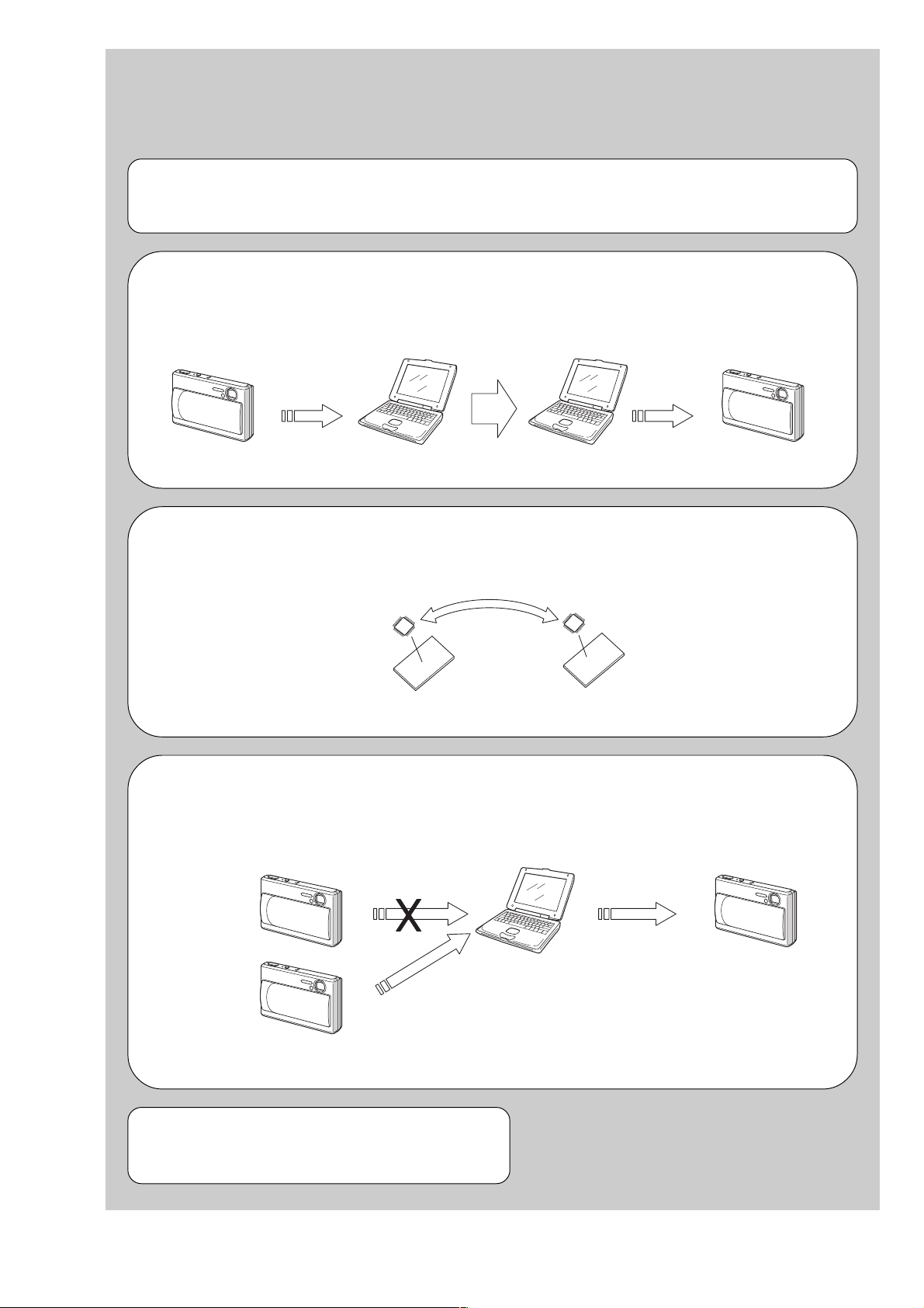
1. Before starting adjustment EVR Data Re-writing Procedure When Replacing Board
The data that is stored in the repair board, is not necessarily correct.
Perform either procedure 1 or procedure 2 or procedure 3 when replacing board.
Procedure 1
Save the EVR data of the machine in which a board is going to be replaced. Do wnload the saved data after a board
is replaced.
(Machine before starting repair)
SECTION 6
ADJUSTMENTS
PC PC
DSC-T1
(Machine after a board is replaced)
Save the EVR data
to a personal computer.
Download the saved
data to a machine.
Procedure 2
Remove the EEPR OM from the board of the machine that is going to be repaired. Install the removed EEPR OM
to the replaced board.
Remove the EEPROM and install it.
(Former board)
(New board)
Procedure 3
When the data cannot be saved due to defective EEPROM, or when the EEPROM cannot be removed or
installed, save the data from the same model of the same destination, and do wnload it.
(Machine to be repaired) (Machine to be repaired)
PC
Save the data.
(The same model of the same destination)
After the EVR data is saved and downloaded, check the
respective items of the EVR data.
(Refer to page 6-2 for the items to be checked.)
Download the data.
6-1
Page 4
DSC-T1
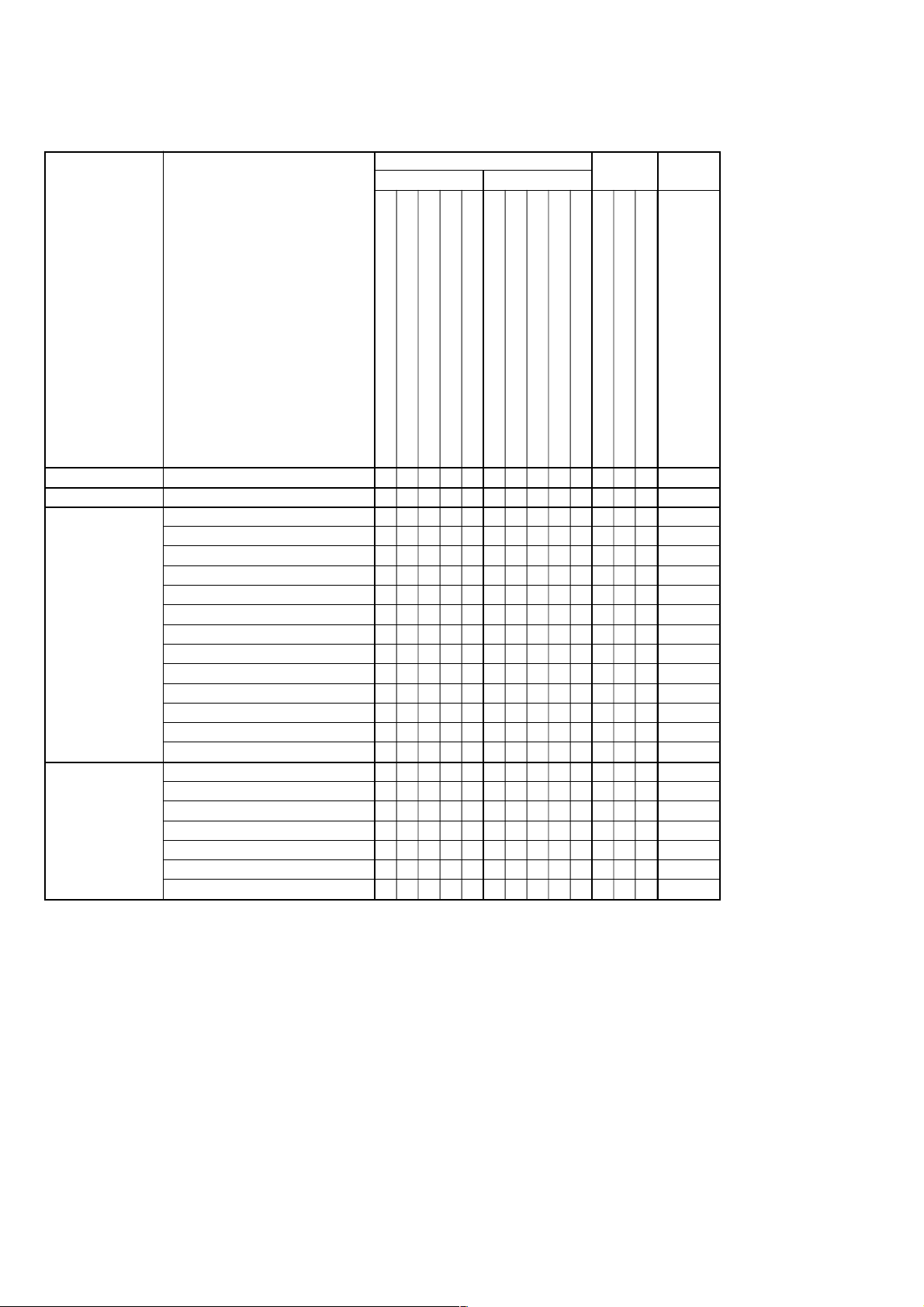
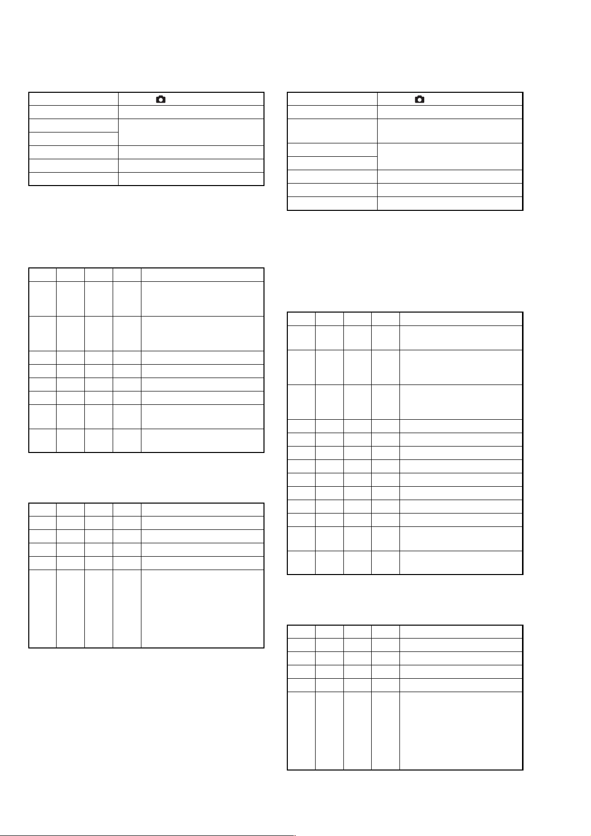
1-1. Adjusting items when replacing main parts and boards.
When replacing main parts and boards, adjust the items indicated by z in the following table.
Replaced parts Board
Block replacement
Parts replacement
replacement
EEPROM
replacement
Adjustment
Section
Initialization of data
Video
Camera
LCD
Adjustment
Initialization of data
Video output level adj.
Wide limit Adj.
Flange back adj.
F No. compensation
Mechanical shutter adj.
Light value adj.
AWB 3200K standard data input
AWB 5800K standard data input
CCD linearity check
Color reproduction adj.
CCD white defect compensation check
CCD black defect compensation check
Strobe adj.
Auto focus illumination check
LCD initial data input
VCO adj.
Bright adj.
Contrast adj.
V COM adj.
White balance adj. (1)
White balance adj. (2)
Table. 6-1-1.
IC803 (RGB drive, Timing.gen.) (LCD)
IC151 (Timing gen. S/H, AGC A/D conv.)
CCD block
Lens device
Xenon tube
LCD block LCD unit (LCD901)
LCD block Back light unit
MS-148 board
ST-86 board D003 (AF Illumination LED)
SY-95 board
SY-95 board IC301 (Camera DSP)
SY-95 board IC302 (Video amp.)
MS-148 board (COMPLETE)
ST-86 board (COMPLETE)
SY-95 board (COMPLETE)
SY-95 board IC501 (Camera system control)
(With built-in flash memory)
zz
zz z z
zzz
zz z z
zz z z z
zz z z z
zz z z z
zz z z z
zz z z z
zz z z z
zz z z z
zz z z z
zz z z z
zzz z z z
zzzzzz
zz
zzzz
zzzz
zzzzz
zz zzz
zzz z z z
zzz z z z
6-2
Page 5

6-1. ADJUSTMENT
1-1. PREPARATIONS BEFORE ADJUSTMENT
1-1-1. List of Service Tools
• Oscilloscope • Color monitor • Vectorscope • AC power adapter
• Calculator which can hexadecimal calculation.
DSC-T1
J-1 J-2 J-3
Filter for color
temperature correction
(C14)
J-6080-058-A
J-4
J-7 J-8
Clear chart for
pattern box
For PTB-450:
J-6080-621-A
For PTB-1450:
J-6020-560-A
Cradle
1-817-742-11
J-5
Pattern box PTB-450
J-6082-200-A
or
Pattern box PTB-1450
J-6082-557-A
J-6
Siemens star chart
J-6080-875-A
J-9
Personal computer
with Windows98/
98SE/ME/2000/XP
installed and with
two USB ports
Clear chart for
pattern box
For PTB-450:
J-6020-250-A
For PTB-1450:
J-6020-559-A
Mini pattern box
J-6082-353-B
USB cable
1-823-073-11
J-10
Application for
adjustment (SEUS)
and HASP key
(Note)
Note : Contact our service headquarter of each area how to get the application for adjustment (SEUS) and HASP key.
J-11
Backgorund
paper
J-2501-130-A
Fig. 6-1-1.
6-3
Page 6
DSC-T1
1-1-2. Preparations
1) Connect the equipment for adjustments according to Fig. 6-1-4.
2) Start up the application for adjustment (SEUS).
Note1: Setting the “Forced Power ON Mode (Forced STILL Mode)”
1) Select page: 00, address: 01, and set data: 01.
2) Select page: 2F, address: 23, and write data: 01.
3) Save the data.
4) Wait for 3 sec.
The above procedure will enable the power (STILL mode) to
be turned on with POWER switch (Control switch block)
disconnected. After completing adjustments, be sure to exit the
“Forced Power ON Mode”.
Note2: Setting the “Forced Power ON Mode (Forced PLAY Mode)”
1) Select page: 00, address: 01, and set data: 01.
2) Select page: 2F, address: 23, and write data: 02.
3) Save the data.
4) Wait for 3 sec.
The above procedure will enable the power (PAL Y mode) to be
turned on with POWER switch (Control switch block)
disconnected. After completing adjustments, be sure to exit the
“Forced Power ON Mode”.
Note3: Exiting the “Forced Power ON Mode”
1) Select page: 00, address: 01, and set data: 01.
2) Select page: 2F, address: 23, and write data: 80.
3) Save the data.
4) Wait for 3 sec.
5) Select page: 00, address: 01, and set data: 00.
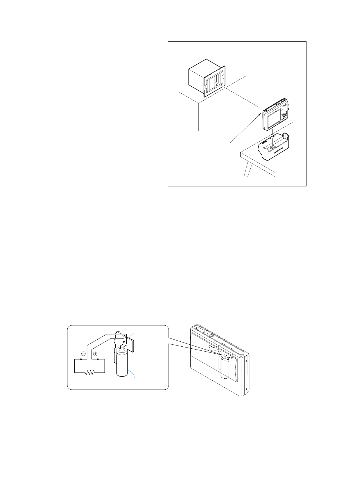
1-1-3. Discharging of the flashlight power supply
The capacitor which is used as power supply of flashlight is charged
with 200V to 300V voltage. When disassembling the unit, dischar ge
this voltage in order to protect service engineers from electric shock.
Pattern box
About 12cm (PTB-1450)
About 30cm (PTB-450)
Front of the lens
Fig. 6-1-2.
Discharge procedure
1. Remove the power supply (AC power adaptor or battery).
2. Fabricate the discharging jig as sho wn in Fig. 6-1-3 locall y by
yourself. Connect the discharging jig to the positive (+) and
negative (-) terminal of the flash v oltage charge capacitor . Allo w
ten seconds to discharge the voltage.
ST-86 BOARD
Shorting jig
(1kΩ / 1w)
Capacitor
Fig. 6-1-3.
6-4
Page 7
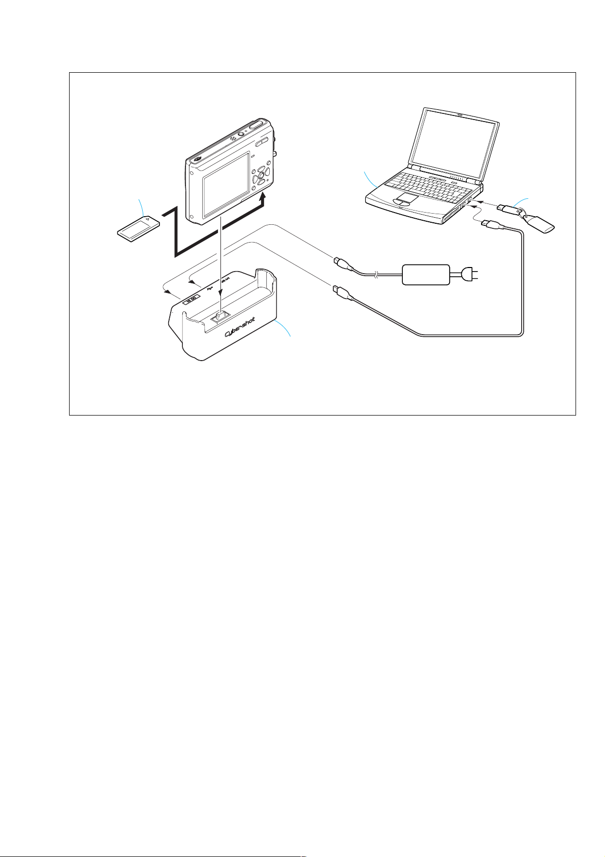
Memory stick DUO
Cradle
Personal computer
(with two USB ports)
AC IN
DC IN
USB
USB1
USB2
HASP key
AC power
adaptor
[CONNECTION OF EQUIPMENT]
DSC-T1
Note: When performing “Flange Back Adjustment”, connect the cables after
disassembling the cradle. Unless the cradle is disassembled, the USB
cable and the power cable will interfere with the flange back adjustment
jig or mini pattern box, and thus the subject cannot be set correctly.
Fig. 6-1-4
6-5
Page 8

DSC-T1
e
1-1-4. Precaution
1. Setting the Switch
Unless otherwise specified, set the switches as follows and perform
adjustments.
Switch settings
1. Mode switch....................................................... STILL (
2. Lens cover...................................................................... Open
3. ZOOM....................................................................WIDE end
2. Order of Adjustments
Basically carry out adjustments in the order given.
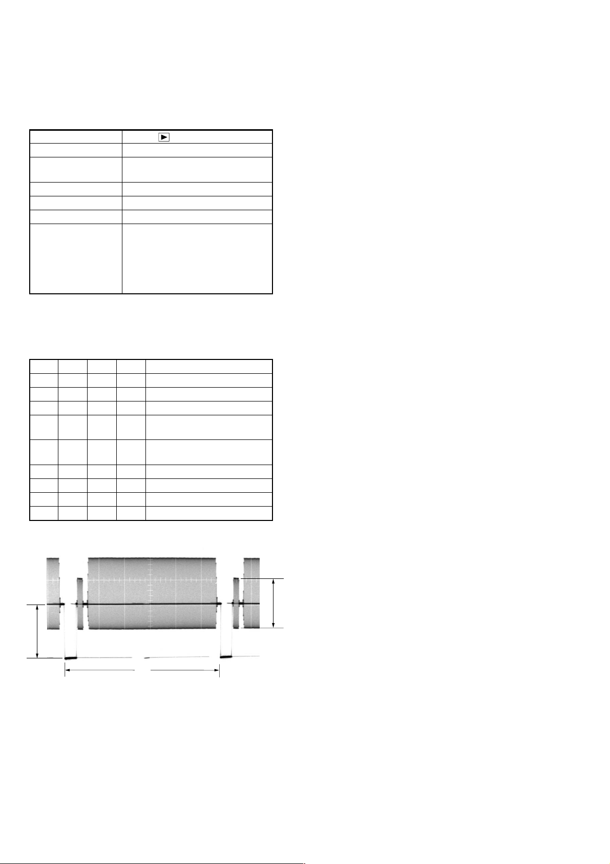
Color bar chart (Standard picture frame)
H
)
3. MACRO (
) .................................................................. ON
4. SCENE (Menu)............................................................... Auto
5. VIDEO OUT (SET UP of Menu) ................................. NTSC
Yellow
AAB
Video terminal
output waveform
Cyan
A=
Fig. a
White
Green
B
2
Magenta
Red
Blue
CD
Enlargement
A
3. Subjects
1) Color bar chart (Standard picture frame)
When performing adjustments using the color bar chart, adjust
the picture frame as shown in Fig. 6-1-5. (Standard picture
frame)
2) Clear chart (Color reproduction adjustment frame)
Remove the color bar chart from the pattern box and insert a
clear chart in its place. (Do not perform zoom operations during
this time.)
C=D
V
Difference in level
Fig.6-1-5.
Cyan
White
Green
Yellow
LCD screen or under scan
Fig. b
monitor TV picture
Adjust the camera position and direction to
obtain the output wavef orm shown in Fig. a
and the LCD screen or the monitor TV
display shown in Fig. b.
Red
Blue
Magenta
Picture fram
6-6
Page 9

4. Preparing the Flash Adjustment Box
m
A
A dark room is required to provide an accurate strobe adjustment.
If it is not available, prepare the flash adjustment box as gi ven below;
1) Provide woody board A, B and C of 15 mm thickness.
DSC-T1
woody board A (2 sheets)
400 mm
513 mm 513 mm 700 m
woody board B (2 sheets)
370 mm
700 mm730 mm
Fig. 6-1-6.
2) Apply black mat paint to one side of woody board A and B.
3) Attach background paper (J-2501-130-A) to woody board C.
4) Assemble so that the black sides and the background paper side
of woody board A, B and C are internal. (Fig. 6-1-7.)
woody board C (1 sheet)
700 mm
woody board A
woody board B
woody board
woody board B
woody board C
Fig. 6-1-7.
6-7
Page 10

DSC-T1
1-2. INITIALIZATION OF DATA
1-2-1. INITIALIZATION OF DATA
1. Initializing All Pages Data
By performing the following procedure, data of all the pages will
be initialized.
Initializing Method:
1) Select page: 00, address: 01, and set data: 01.
2) Click [Sector Write] on the SEUS screen to display the SEUS
SECTOR WRITE screen.
3) Check that the SET ID is “04”.
4) Click [All] of the ALL SELECT buttons to select all pages.
(Fig. 6-1-8. A)
5) Click [Write] to write the initializing data to the EEPROM of
the camera.
6) Wait for 3 sec.
7) Click [Close] to close the SEUS PAGE EDIT screen.
Modification of 4F, 8E Page Data
If all page data have been initialized, change the data of the “Fixed
data-2” address shown in the following tables by manual input.
1) Select page: 00, address: 01, and set data: 01.
2) Click [Page] on the SEUS screen, and input “4F” or “8E”.
3) Click [Address], and input the “Fixed data-2” address.
4) Click [Set], and input the new data.
Note: New data for changing are not shown in the table because they
are different in destination. When changing the data, copy the
data built in the same model. If copy the data built in the different
model, the camera may not operate.
5) Repeat steps 2 to 4 until all data of the “Fixed data-2” addresses
are changed.
6) Click [Save] to write the changed data to the EEPROM of the
camera.
7) Wait for 3 sec.
2. Initializing Single Page Data
By performing the following procedure, data of the page that you
want to initialize will be initialized.
Initializing Method:
1) Select page: 00, address: 01, and set data: 01.
2) Click [Sector Write] on the SEUS screen to display the SEUS
SECTOR WRITE screen.
3) Check that the SET ID is “04”.
4)
Click [All] of the option buttons of the target page. (Fig. 6-1-8. B)
5) Click [Write] to write the initializing data to the EEPROM of
the camera.
6) Wait for 3 sec.
7) Click [Close] to close the SEUS PAGE EDIT screen.
Note: When 4F page or 8E page is initialized, perform “Modification of
4F, 8E Page Data”. (Refer to “1. Initializing All Pages Data”.)
Processing after Completing Initializing of data
Order Page
Address
Data Procedure
1 20 00 29 Set the data.
2 20 01 29 Set the data.
3 Check “Receive Paket Error” is
displayed on the SEUS screen.
4 Turn on the po wer of the camera.
5 Click [Connect] on the SEUS
screen.
B
Processing after Completing Initializing of data
Order Page
Address
Data Procedure
1 20 00 29 Set the data.
2 20 01 29 Set the data.
3 Check “Receive Paket Error” is
displayed on the SEUS screen.
4 Turn on the po wer of the camera.
5 Click [Connect] on the SEUS
screen.
A
Fig. 6-1-8.
6-8
Page 11
DSC-T1
3. 2F Page Adjustment Address
Address Remark
Initial value
23 80 Test mode
Table. 6-1-2.
4. 4F Page Adjustment Address
Address Remark
46
47
88
94
95
96
97
A1
Initial value
00
00
00
00
Fixed data-2
Fixed data-2
Fixed data-2
Recording counter
(Refer to “Record of Use check” of
“SERVICE MODE”.)
Fixed data-2
Table. 6-1-3.
5. 6E Page Adjustment Address
Address Remark
00
01
02
03
04
05
06
07
08
09
0A
0B
0C
0D
0E
0F
10
11
12
13
14
15
16
17
18
19
1A
1B
1C
1D
1E
1F
20
21
Initial value
00
00
00
00
21
00
0C
00
20
00
0D
00
21
00
0C
00
20
00
0D
00
21
00
0C
00
20
00
0D
00
00
00
00
00
00
00
AWB 5800K standard data input
AWB 3200K standard data input
Address Remark
24
25
26
27
28
29
2A
2B
2C
2D
2E
2F
30
31
32
33
34
35
36
37
38
39
3A
3B
3C
3D
3E
3F
40
41
60
61
62
63
64
65
66
67
72
73
74
75
Initial value
13
00
13
00
13
00
15
00
13
00
13
00
13
00
15
00
13
00
13
00
13
00
15
00
00
00
00
00
00
00
F1
FB
5E
65
F8
06
69
5C
12
00
18
00
AWB 5800K standard data input
Color reproduction adj.
Strobe adj.
Table. 6-1-4.
6-9
Page 12
DSC-T1
6. 6F Page Adjustment Address
Address Remark
10
11
12
13
14
15
16
17
18
19
1A
1B
1C
1D
1E
1F
20
21
22
23
24
25
26
27
28
29
2A
2B
2C
2D
2E
2F
30
31
32
33
34
35
36
37
38
39
3A
3B
3C
3D
3E
3F
40
41
42
43
44
45
46
Initial value
FF
FF
FF
FF
FF
FF
FF
FF
1C
E8
20
A8
1D
88
00
00
00
00
00
00
20
20
80
46
0A
00
00
00
00
00
00
00
00
00
00
00
00
00
00
00
00
00
00
00
00
00
FF
FF
00
00
00
00
00
00
00
AF illumination check
Wide limit adj./Flange back adj.
Flange back adj.
Wide limit adj/
Flange back adj
Flange back adj.
Address Remark
47
48
49
4A
4B
4C
4D
4E
4F
50
51
52
53
60
61
62
63
64
65
66
67
6B
6C
6D
B8
B9
BA
BB
BC
BD
BE
BF
C0
C1
C2
C3
C4
C5
C6
C7
C8
C9
CA
CB
CC
CD
CE
CF
D0
D1
D2
D3
D4
D5
D6
D7
Initial value
00
00
00
00
00
00
00
00
00
00
00
00
00
00
00
00
00
00
30
FE
6D
FF
00
00
10
6B
0F
F6
0F
F7
0F
F2
0F
F7
00
00
00
00
00
30
1B
12
0D
08
80
88
98
90
88
00
00
00
00
00
00
14
Flange back adj.
F No. standard data input
Light value adj.
F No. standard data input/
Mechanical shutter adj.
Mechanical shutter adj.
6-10
Page 13
6F page
Address Remark
DD
DE
EA
ED
D8
D9
DA
DB
DC
DF
E0
E1
E2
E3
E4
E5
E6
E7
E8
E9
EB
EC
EE
EF
Initial value
FF
FF
FF
00
00
00
00
00
00
00
00
00
00
00
00
00
00
00
00
00
00
00
00
00
Strobe adj.
7. 8E Page Adjustment Address
Address Remark
C8 Fixed data-2
Table. 6-1-6.
8. 8F Page Adjustment Address
Address Remark
23
24
25
28
29
2A
2B
2C
D0
Initial value
80
A2
91
80
80
80
80
45
80
VCO adj. (LCD)
V COM adj. (LCD)
Bright adj. (LCD)
White balance adj.(1) (LCD)
White balance adj.(2) (LCD)
White balance adj.(1) (LCD)
White balance adj.(2) (LCD)
Contrast adj. (LCD)
Video output level adj.
Table. 6-1-7.
DSC-T1
Table. 6-1-5.
6-11
Page 14
DSC-T1
1-3. VIDEO SYSTEM ADJUSTMENTS
1. Video Output Level Adjustment (SY-95 board)
Adjust the sync level of the composite video signal output.
Mode PLAY ( )
Signal No signal
Measurement Point Video terminal of AV OUT jack
of the cradle (75Ω terminated)
Measuring Instrument Oscilloscope
Adjustment Page 8F
Adjustment Address D0
Specified Value Sync level:
A=286 ± 5mV (NTSC mode)
A=300 ± 5mV (PAL mode)
Burst level:
B=286 ± 30mV (NTSC mode)
B=300 ± 30mV (PAL mode)
Switch setting:
VIDEO OUT (SETUP 2)......................................... (NTSC mode)
............................................ (PAL mode)
Adjusting method:
Order Page
1 00 01 01 Set the data.
260C1
3 80 70 01 Set the data.
4 8F D0 Change the data and set the sync
5 Check that the burst level (B)
6 80 70 00 Write the data.
7 Save the data.
8 Wait for 3 sec.
9 00 01 00 Set the data.
A
Address
Data Procedure
Read the data, and check it is “01”.
level (A) to the specified value.
satisfies the specified value.
B
H
Fig. 6-1-8.
6-12
Page 15
1-4. CAMERA SYSTEM ADJUSTMENTS
Before perform the camera system adjustments, check that the
specified values of “VIDEO SYSTEM ADJUSTMENT” are
satisfied.
1. Data Setting during Camera System Adjustments
Perform the following data setting before the camera system
adjustments.
Note: When the power is turned off, some data settings will be released.
So perform this data setting again when the power is turned off.
Order Page
1 00 01 01 Set the data.
2 4F B7 01 Set the data.
3 2F 23 01 Set the data.
4 60 C1 Read the data, and check it is “02”.
5 80 70 01 Set the data.
6 60 6C 01 Set the data.
7 60 2C 01 Set the data.
Address
Data Procedure
DSC-T1
After completing the camera system adjustments, release the
data setting.
Order Page
1 00 01 01 Set the data.
2 4F B7 00 Set the data.
3 2F 23 80 Set the data.
4 Save the data.
5 Wait for 3 sec.
6 00 01 00 Set the data.
Address
Data Procedure
6-13
Page 16

DSC-T1
2. Wide Limit Adjustment
Adjusted the dispersion of the wide-end of the inner focus lens.
Adjustment Page 6F
Adjustment Address 18, 19
2-1. Adjusting method when the lens device is replaced:
Adjusting method:
Order Page
Address
Data Procedure
1 00 01 01 Set the data.
2 6F 18 Set the data. (Note)
3 6F 19 Set the data. (Note)
4 7C 16 00 Set the data.
5 Save the data.
6 Wait for 3 sec.
7 Perform “Flange Back
Adjustment”.
Note: The data of the addresses 18 and 19, which must be set at Steps 2
and 3, are written on the lens device for service replacement. Four
digits hexadecimal number is written on the lens. Please set the upper
2 digits of the number to the address 18, and set the lower 2 digits to
the address 19.
2-2. Adjusting method when it is not necessary to
replace the lens device and when the SY-95 board
is replaced:
When the data of page: 6F, address: 18 and 19 can be
read from the defective board before replacing it. And
when both of the data are not “00”.
Processing after Completing Adjustments:
Order Page
Address
Data Procedure
1 00 01 01 Set the data.
2 6F 18 Set the read data.
3 6F 19 Set the read data.
4 7C 16 00 Set the data.
5 Save the data.
6 Wait for 3 sec.
7 Perform “Flange Back
Adjustment”.
When the data of page: 6F, address: 18 and 19 can be
read from the defective board before replacing it. And
when both of the data are “00”.
1) Replace the lens device and perform “2-1. Adjusting method when
the lens device is replaced.”
When the data of page: 6F, address: 18 and 19 cannot be
read from the defective board.
1) Replace the lens device and perform “2-1. Adjusting method
when the lens device is replaced.”
Fig.6-1-10.
Note: The data of address 16 of page 7C, set at Step 4 of the adjustment
method of 2-1 and 2-2, is “01” in the state of shipment of the factory.
However, it is “00” when it is adjusted according to the service
manual.
6-14
Page 17
DSC-T1
3. Flange Back Adjustment
The inner focus lens flange back adjustment is carried out
automatically. In whiche v er case, the focus will be de viated during
auto focusing/manual focusing.
Mode STILL ( )
Subject Flange back adjustment jig or
minipattern box (Siemens star chart
with ND filter (Note1))
Measurement Point Data of page: 6F, address: 24, 3E, 3F
Measuring Instrument
Adjustment Page 6F
Adjustment Address 18 to 53
Specified value1 00
Specified value2 0A to 40
Note1: Dark siemens star chart.
Note2: If the data of page: 60, address: 02 is “01”, select page: 60, address:
01, and set data: 00.
Note3: When performing “Flange Back Adjustment”, connect the cables
after disassembling the cradle. Unless the cradle is disassembled,
the USB cable and the power cable will interfere with the flange
back adjustment jig or mini pattern box, and thus the subject cannot
be set correctly.
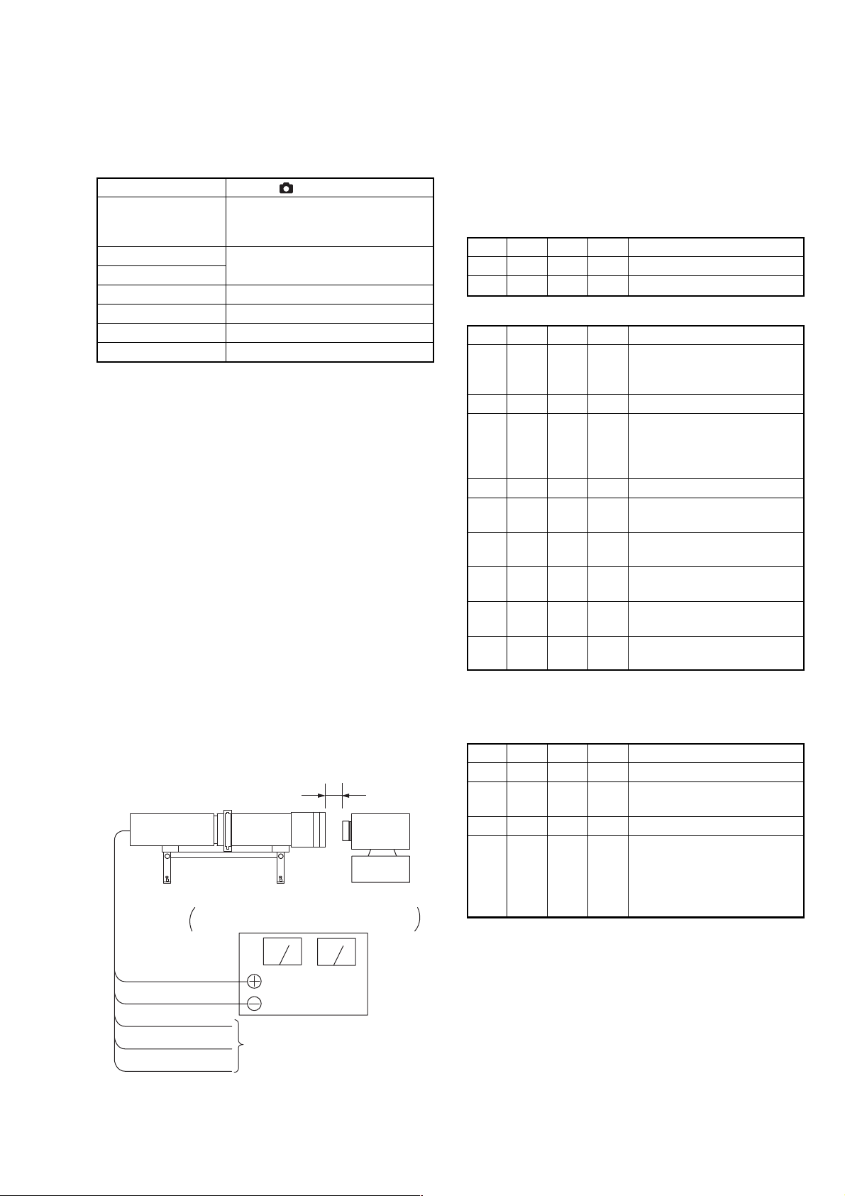
Preparations for the minipattern box:
1) The minipattern box is installed as shown in the following
figure.
Note: The attachment lenses are not used.
2) Install the minipattern box so that the distance between it and
the front of the lens of the camera is less than 3cm.
3) Make the height of the minipattern box and the camera equal.
4) Check that the output voltage of the regulated power supply is
the specified voltage.
5) Check that at both the zoom lens TELE end and WIDE end,
the center of the siemens star chart and center of the exposure
screen coincide.
Specified voltage:
The specified voltage varies according to the minipattern box, so
adjust the power supply output voltage to the specified voltage
written on the sheet which is supplied with the minipattern box.
Below 3 cm
Minipattern box
Camera
Regulated power supply
Output voltage : Specified voltage ±0.01Vdc
Output current : more than 3.5A
Preparations for the flange back adjustment jig:
1) Install the flange back adjustment jig so that the distance
between it and the front of the lens of the camera is less than
3cm.
2) Adjust the illumination intensity to the chart of the flange back
adjustment jig. (300 to 400 lux)
Data setting when the lens device is replaced:
Note4: Perform this data setting only when the lens device is replaced.
Order Page
Address
Data Procedure
1 00 01 01 Set the data.
2 6F 3E FF Set the data.
Adjusting method:
Order Page
Address
Data Procedure
1 Check that “1. Data Setting
during Camera System
Adjustments” is performed.
2 60 01 13 Set the data.
3 Wait for 1sec.
When the flange back
adjustment jig is used, check
that optimum image is obtained.
4 60 01 27 Set the data.
5 Wait until the movement of the
lens stops.
6 60 02 Read the data, and check it is “01”.
(Note5)
7 6F 3E Read the data, and check it
satisfies the specified value 1.
8 6F 3F Read the data, and check it
satisfies the specified value 1.
9 6F 24 Read the data, and check it
satisfies the specified value 2.
Note5: The adjustment data will be automatically input to page: 6F,
address: 18 to 53
Processing after Completing Adjustments:
Order Page
Address
Data Procedure
1 60 01 00 Set the data.
2 Turn off the power and turn on
again.
3 Perform “Flange Back Check”.
4 If finish the camera system
adjustments, release the data
setting.
(See “1. Data Setting during
Camera System Adjustments”.)
Red (+)
Black (–)
Yellow (SENS +)
White (SENS –)
Black (GND)
Need not connected
Fig.6-1-11.
6-15
Page 18

DSC-T1
4. Flange Back Check
Mode STILL ( )
Subject Siemens star
(1.0 m from the front of the lens)
(Luminance : 200 to 400 lux)
Measurement Point Check operation on TV monitor
(under scan mode)
Measuring Instrument
Specified Value The lens is focused.
Switch setting:
ZOOM ........................................................................... TELE end
MACRO ( ).........................................................................OFF
Checking method:
Order Page
1 Turn off the power and turn on
2 Place the siemens star 1.0 m from
3 Shoot the siemens star with the
4 60 8C 30 Set the data.
5 Observe the TV monitor and
6 60 2C 01 Set the data.
7 Press the ZOOM WIDE button
8 Shoot the Siemens star with the
9 Observe the TV monitor and
Address
Data Procedure
again
the front of the lens.
zoom TELE end.
check that the lens is focused.
and check that zoom operation is
normal.
zoom WIDE end.
check that the lens is focused.
Processing after Completing Adjustments:
Order Page
1 60 8C 00 Set the data.
Address
Data Procedure
6-16
Page 19

5. Picture Frame Setting
E=F
V
EF
Color bar chart picture frame
Effective picture frame
ABC
Mode STILL ( )
Subject Color bar chart and clear chart
(Standard picture frame)
About 30cm (PTB-450) or 12cm
(PTB-1450) from the front of the lens
Measurement Point Video terminal of A/V OUT jack of
the cradle
Measuring Instrument Oscilloscope and TV monitor
Specified Value A=C=B/2, E=F
Switch setting:
ZOOM ...........................................................................WIDE end
MACRO ( ).......................................................................... ON
SCENE (Menu setting)........................................................ AUTO
Setting method:
Order Page
Address
Data Procedure
1 Turn off the power and turn on
again
2 Shoot the color bar chart with
the zoom WIDE end.
3 Adjust the direction and distance
between the pattern box and
camera, and set the picture frame
to the specified position.
4 Perform “1. Data Setting during
Camera System Adjustments”.
5 Remove the color bar chart and
set the clear chart.
6 Check that the whole of the screen
is white. If not, adjust the direction
and distance slightly.
7 10 44 Read the data, and this data named
YH.
8 10 45 Read the data, and this data named
YL.
9 Perform the following
adjustments.
How to reset the zoom and focus when they deviated:
If the zoom and focus deviated due to some reason reset them in the
following method.
Order Page
Address
Data Procedure
1 60 90 00 Set the data.
2 60 91 00 Set the data.
3 60 92 YL Set the data. Note
4 60 93 YH Set the data. Note
5 60 01 79 Set the data.
6 Wait until the movement of the
lens stops.
7 60 07 Read the data, and check it is “01”.
8 60 01 00 Set the data.
Check on an oscilloscope
1. Horizontal period
A
A = C =
B
2
B
C
Fig. 6-1-12.
2. V ertical period
Fig. 6-1-13.
Check on the monitor TV (Underscanned mode)
DSC-T1
Note: YH and YL are the data read in the “Setting method”.
Fig. 6-1-14.
6-17
Page 20
DSC-T1
6. F No. Compensation
Adjusted the dispersion of the iris to every to every F number, and
compensate the exposure.
Mode STILL ( )
Subject Clear chart (Standard picture frame)
Measurement Point Data of page: 6F, address: 6B
Measuring Instrument
Adjustment Page 6F
Adjustment Address 60 to 64, 6B to 6D
Specified value 00
Note1:If the data of page: 60, address: 02 is “01”, select page: 60, address:
01, and set data: 00.
Switch setting:
ZOOM ...........................................................................WIDE end
Adjusting method:
Order Page
Address
Data Procedure
1 Check that “1. Data Setting during
Camera System Adjustments” is
performed.
2 Check the picture frame. If
deviated, perform “5. Picture
Frame Setting”.
3 60 01 BB Set the data.
4 Wait for 15 sec.
5 60 02 Read the data, and check it is “01”.
(Note2)
6 6F 6B Read the data, and check it
satisfies the specified value.
Note2: The adjustment data will be automatically input to page: 6F,
address: 60 to 64, 6B to 6D.
Processing after Completing Adjustments:
Order Page
Address
Data Procedure
1 60 01 00 Set the data.
2 If finish the camera system
adjustments, release the data
setting.
(See “1. Data Setting during
Camera System Adjustments”.)
7. Mechanical Shutter Adjustment
Adjust the dispersion of the opening/closing time and the closing
loss rate of the mechanical shutter. and compensate the exposure.
Mode STILL ( )
Subject Clear chart (Standard picture frame)
Measurement Point Data of page: 6F, address: 6B
Measuring Instrument
Adjustment Page 6F
Adjustment Address 6B to 6D, B8 to D7
Specified value 00
Note1: If the data of page: 60, address: 02 is “01”, select page: 60, address:
01, and set data: 00.
Switch setting:
ZOOM ...........................................................................WIDE end
Adjusting method:
Order Page
Address
Data Procedure
1 Check that “1. Data Setting during
Camera System Adjustments” is
performed.
2 Check the picture frame. If
deviated, perform “5. Picture
Frame Setting”.
3 60 01 AD Set the data.
4 Wait until the movement of the
shutter stops.
5 60 02 Read the data, and check it is “01”.
(Note2)
6 6F 6B Read the data, and check it
satisfies the specified value.
Note2: The adjustment data will be automatically input to page: 6F,
address: 6B to 6D, B8 to D7.
Processing after Completing Adjustments:
Order Page
Address
Data Procedure
1 60 01 00 Set the data.
2 If finish the camera system
adjustments, release the data
setting.
(See “1. Data Setting during
Camera System Adjustments”.)
6-18
Page 21

DSC-T1
8. Light Value Adjustment
Adjust the standard LV value.
Mode STILL ( )
Subject Clear chart (Standard picture frame)
Measurement Point Data of page: 10, address: 0C, 0D
Measuring Instrument Data of page: 6F, address: 65
Adjustment Page 6F
Adjustment Address 65 to 67
Specified value1 0FE0 to 1020
Specified value2 30 to 60
Specified value3 00 to 26
Note1: If the data of page: 60, address: 02 is “01”, select page: 60, address:
Switch setting:
ZOOM ...........................................................................WIDE end
Adjusting method:
01, and set data: 00.
Order Page
1 Check that “1. Data Setting during
2 Check the picture frame. If
3 60 01 0D Set the data.
4 Wait for 2 sec.
5 60 02 Read the data, and check it is “01”.
6 10 0C Read the data, and this data is
7 10 0D Read the data, and this data is
8 Calculate DLV using the
9 Check that DLV satisfies the
10 6F 65 Read the data, and check it
11 60 01 00 Set the data.
12 Wait for 1 sec.
13 60 12 A2 Set the data.
14 60 13 A8 Set the data.
15 60 14 8A Set the data.
16 Wait for 1 sec.
17 10 0C Read the data, and this data is
18 10 0D Read the data, and this data is
19 Calculate DAE using the
20 77 5E 00 Set the data.
21 Wait for 1 sec.
22 10 0C Read the data, and this data is
Address
Data Procedure
Camera System Adjustments” is
performed.
deviated, perform “5. Picture
Frame Setting”.
(Note2)
named D0C.
named D0D.
following equation
(Hexadecimal calculation)
DLV = D0C × 100 + D0D
specified value1.
satisfies the specified value2.
named D0C.
named D0D.
following equation
(Hexadecimal calculation)
DAE = D0C × 100 + D0D
named D0C.
Order Page
23 10 0D Read the data, and this data is
24 Calculate DAE100 using the
25 Check that the difference of DAE
Note2: The adjustment data will be automatically input to page: 6F,
Processing after Completing Adjustments:
Order Page
1 60 01 00 Set the data.
2 60 12 00 Set the data.
3 60 13 00 Set the data.
4 60 14 00 Set the data.
5 77 5E 1E Set the data.
6 Save the data.
7 Wait for 3 sec.
8 Perform next adjustment. If finish
Address
address: 65 to 67.
Address
Data Procedure
named D0D.
following equation
(Hexadecimal calculation)
DAE100 = D0C × 100 + D0D
and DAE100 satisfies the specified
value3. (Hexadecimal).
Data Procedure
the camera system adjustments,
release the data setting. (See “1.
Data Setting during Camera
System Adjustments”.)
6-19
Page 22
DSC-T1
9. Auto White Balance 3200K Standard Data Input
Adjust the white balance standard data at 3200K.
Mode STILL ( )
Subject Clear chart (Standard picture frame)
Measurement Point Data of page: 6E, address: 4F
Measuring Instrument
Adjustment Page 6E
Adjustment Address 04 to 21
Specified value 00
Note1: If the data of page: 60, address: 02 is “01”, select page: 60, address:
01, and set data: 00.
Switch setting:
ZOOM ...........................................................................WIDE end
Adjusting method:
Order Page
Address
Data Procedure
1 Check that “1. Data Setting
during Camera System
Adjustments” is performed.
2 Check the picture frame. If
deviated, perform “5. Picture
Frame Setting”.
3 6E 4F FF Set the data.
4 60 36 01 Set the data.
5 60 01 0B Set the data.
6 Wait for 5 sec.
7 60 02 Read the data, and check it is “01”.
(Note2)
8 6E 4F Read the data, and check it
satisfies the specified value.
Note2: The adjustment data will be automatically input to page: 6E,
address: 04 to 21.
Processing after Completing Adjustments:
Order Page
Address
Data Procedure
1 60 01 00 Set the data.
2 60 36 00 Set the data.
3 Wait for 1 sec.
4 60 37 Read the data, and check it is “00”.
5 Perform “Auto White Balance
5800K Standard Data Input”.
If finish the camera system
adjustments, release the data
setting. (See “1. Data Setting
during Camera System
Adjustments”.)
10.Auto White Balance 5800K Standar d Data Input
Adjust the white balance standard data at 5800K.
Mode STILL ( )
Subject Clear chart (Standard picture frame)
Filter Filter C14 for color temperature
correction
Measurement Point Data of page: 6E, address: 4F
Measuring Instrument
Adjustment Page 6E
Adjustment Address 00 to 03, 24 to 41
Specified value 00
Note1: Before perform this adjustment, perform “Auto White Balance
Note2: If the data of page: 60, address: 02 is “01”, select page: 60, address:
3200K Standard Data Input”.
01, and set data: 00.
Switch setting:
ZOOM ...........................................................................WIDE end
Adjusting method:
Order Page
Address
Data Procedure
1 Place the C14 filter for color
temperature correction on the lens.
2 Check that “1. Data Setting during
Camera System Adjustments” is
performed.
3 Check the picture frame. If
deviated, perform “5. Picture
Frame Setting”.
4 6E 00 00 Set the data.
5 6E 01 00 Set the data.
6 6E 02 00 Set the data.
7 6E 03 00 Set the data.
8 6E 4F FF Set the data.
9 60 36 02 Set the data.
10 60 01 A5 Set the data.
11 Wait for 5 sec.
12 60 02 Read the data, and check it is
“01”. (Note3)
13 6E 4F Read the data, and check it
satisfies the specified value.
Note3: The adjustment data will be automatically input to page: 6E,
address: 24 to 41.
Processing after Completing Adjustments:
Order Page
Address
Data Procedure
1 60 01 00 Set the data.
2 60 36 00 Set the data.
3 Wait for 1 sec.
4 60 37 Read the data, and check it is “00”.
5 Perform “Auto White Balance
5800K Check”.
If finish the camera system
adjustments, release the data
setting.
(See “1. Data Setting during
Camera System Adjustments”.)
6-20
Page 23

DSC-T1
11.Auto White Balance 5800K Check
Check that the white balance standard data at 5800K are inputted
properly.
Mode STILL ( )
Subject Clear chart (Standard picture frame)
Filter Filter C14 for color temperature
correction
Measurement Point Data of page: 6E, address: 4F
Measuring Instrument
Specified value 00
Note1: Before perform this adjustment, perform “Auto White Balance
Note2: If the data of page: 60, address: 02 is “01”, select page: 60, address:
5800K Standard Data Input”.
01, and set data: 00.
Switch setting:
ZOOM ...........................................................................WIDE end
Adjusting method:
Order Page
Address
Data Procedure
1 Place the C14 filter for color
temperature correction on the lens.
2 Check that “1. Data Setting during
Camera System Adjustments” is
performed.
3 Check the picture frame. If
deviated, perform “5. Picture
Frame Setting”.
4 6E 4F FF Set the data.
5 60 36 04 Set the data.
6 60 01 3F Set the data.
7 Wait for 10 sec.
8 60 02 Read the data, and check it is “01”.
9 6E 4F Read the data, and check it
satisfies the specified value.
Processing after Completing Adjustments:
Order Page
Address
Data Procedure
1 60 01 00 Set the data.
2 60 36 00 Set the data.
3 Wait for 1 sec.
4 60 37 Read the data, and check it is “00”.
5 Remove the C14 filter.
6 Perform next adjustments.
If finish the camera system
adjustments, release the data
setting.
(See “1. Data Setting during
Camera System Adjustments”.)
12.Auto White Balance 3200K Check
Check that the white balance standard data at 3200K are inputted
properly.
Mode STILL ( )
Subject Clear chart (Standard picture frame)
Measurement Point Data of page: 6E, address: 4F
Measuring Instrument
Specified value 00
Note1: Before perform this adjustment, perform “Auto White Balance
Note2: If the data of page: 60, address: 02 is “01”, select page: 60, address:
3200K Standard Data Input”.
01, and set data: 00.
Switch setting:
ZOOM ...........................................................................WIDE end
Adjusting method:
Order Page
Address
Data Procedure
1 Check that “1. Data Setting during
Camera System Adjustments” is
performed.
2 Check the picture frame. If
deviated, perform “5. Picture
Frame Setting”.
3 6E 4F FF Set the data.
4 60 36 03 Set the data.
5 60 01 0F Set the data.
6 Wait for 10 sec.
7 60 02 Read the data, and check it is “01”.
8 6E 4F Read the data, and check it
satisfies the specified value.
Processing after Completing Adjustments:
Order Page
Address
Data Procedure
1 60 01 00 Set the data.
2 60 36 00 Set the data.
3 Wait for 1 sec.
4 60 37 Check the data, and check it is
“00”.
5 Perform next adjustments.
If finish the camera system
adjustments, release the data
setting.
(See “1. Data Setting during
Camera System Adjustments”.)
6-21
Page 24

DSC-T1
13.CCD Linearity Check
Data picking is done to keep output linearity of the CCD imager,
even if the input level of CCD imager changes.
Mode STILL ( )
Subject Clear chart (Standard picture frame)
Measurement Point
Measuring Instrument
Specified value1 97 to 103 (Note1)
Specified value2 94 to 106 (Note1)
Specified value3 92 to 108 (Note1)
Note1: Decimal number.
Note2: If the data of page: 60, address: 02 is “01”, select page: 60, address:
Note3: For the bit values, refer to “6-2. SERVICE MODE”, “2-2. 2. Bit
Switch setting:
ZOOM ...........................................................................WIDE end
Preparation:
01, and set data: 00.
value discrimination”.
Order Page
1 Check that “1. Data Setting during
2 Check the picture frame. If
3 75 09 Read the data, and memorize it.
4 75 09 04 Set the data.
5 77 F6 Read the data, and memorize it.
6 77 F6 Set Bit2 of the data to “0”. (Note3)
7 77 F7 Read the data, and memorize it.
8 77 F7 Set Bit6 of the data to “1”. (Note3)
9 77 F2 Read the data, and memorize it.
10 77 F2 Set Bit6 of the data to “0”. (Note3)
11 77 F2 Set Bit0 of the data to “0”. (Note3)
12 77 72 Read the data, and memorize it.
13 60 14 90 Set the data.
14 60 12 9F Set the data.
15 60 05 16 Set the data.
16 75 17 Read the data, and memorize it.
17 75 17 50 Set the data.
18 75 18 Read the data, and memorize it.
19 75 18 00 Set the data.
20 75 19 Read the data, and memorize it.
21 75 19 EC Set the data.
22 75 1A Read the data, and memorize it.
23 75 1A 27 Set the data.
24 75 1B Read the data, and memorize it.
25 75 1B 53 Set the data.
26 Wait for 2 sec.
Address
Data of page: 10, address: 80, 81, 82, 83
Data Procedure
Camera System Adjustments” is
performed.
deviated, perform “5. Picture
Frame Setting”.
Checking method:
Order Page
1 Perform “Preparation” before this
2 60 01 F9 Set the data.
3 Wait for 3 sec.
4 60 E1 Read the data, and check it is “08”.
5 10 80 Read the data, and this data is
6 10 81 Read the data, and this data is
7 Calculate DRG0 using the
8 10 82 Read the data, and this data is
9 10 83 Read the data, and this data is
10 Calculate DBG0 using the
11 60 01 00 Set the data.
12 60 E1 00 Set the data.
13 77 72 54 Set the data.
14 Wait for 2 sec.
15 60 01 F9 Set the data.
16 Wait for 3 sec.
17 60 E1 Read the data, and check it is “08”.
18 10 80 Read the data, and this data is
19 10 81 Read the data, and this data is
20 Calculate DRG1 using the
21 10 82 Read the data, and this data is
22 10 83 Read the data, and this data is
23 Calculate DBG1 using the
24 60 01 00 Set the data.
25 60 E1 00 Set the data.
26 77 72 0A Set the data.
27 60 12 A2 Set the data.
28 Wait for 2 sec.
29 60 01 F9 Set the data.
30 Wait for 3 sec.
31 60 E1 Read the data, and check it is “08”.
32 10 80 Read the data, and this data is
33 10 81 Read the data, and this data is
Address
Data Procedure
adjustment.
named D80.
named D81.
following equation
(Hexadecimal calculation)
DRG0 = D80 × 100 + D81
named D82.
named D83.
following equation
(Hexadecimal calculation)
DBG0 = D82 × 100 + D83
named D80.
named D81.
following equation
(Hexadecimal calculation)
DRG1 = D80 × 100 + D81
named D82.
named D83.
following equation
(Hexadecimal calculation)
DBG1 = D82 × 100 + D83
named D80.
named D81.
6-22
Page 25

DSC-T1
Order Page
34 Calculate DRG2 using the
35 10 82 Read the data, and this data is
36 10 83 Read the data, and this data is
37 Calculate DBG2 using the
38 60 01 00 Set the data.
39 60 E1 00 Set the data.
40 77 72 0A Set the data.
41 Wait for 2 sec.
42 60 01 F9 Set the data.
43 Wait for 3 sec.
44 60 E1 Read the data, and check it is “08”.
45 10 80 Read the data, and this data is
46 10 81 Read the data, and this data is
47 Calculate DRG3 using the
48 10 82 Read the data, and this data is
49 10 83 Read the data, and this data is
50 Calculate DBG3 using the
51 Convert DRG0, DBG0, DRG1, DBG1,
52
53 Check that R/G ratio (1) satisfies
54 Check that B/G ratio (1) satisfies
Address
Data Procedure
following equation
(Hexadecimal calculation)
DRG2 = D80 × 100 + D81
named D82.
named D83.
following equation
(Hexadecimal calculation)
DBG2 = D82 × 100 + D83
named D80.
named D81.
following equation
(Hexadecimal calculation)
DRG3 = D80 × 100 + D81
named D82.
named D83.
following equation
(Hexadecimal calculation)
DBG3 = D82 × 100 + D83
DRG2, DBG2, DRG3 and DBG3 to
decimal number, and obtain
DRG0’, DBG0’, DRG1’, DBG1’, DRG2’,
DBG2’, DRG3’ and DBG3’.
Calculate R/G ratio (1), B/G ratio
(1),
R/G ratio (2), B/G ratio (2),
R/G ratio (3) and B/G ratio (3),
using the following equations
(Decimal calculation)
R/G ratio (1) = (DRG1’ / DRG0’) × 100
B/G ratio (1) = (DBG1’ / DBG0’) × 100
R/G ratio (2) = (DRG2’ / DRG0’) × 100
B/G ratio (2) = (DBG2’ / DBG0’) × 100
R/G ratio (3) = (DRG3’ / DRG0’) × 100
B/G ratio (3) = (DBG3’ / DBG0’) × 100
the specified value 1.
(Decimal number)
the specified value 1.
(Decimal number)
Order Page
55 Check that R/G ratio (2) satisfies
56 Check that B/G ratio (2) satisfies
57 Check that R/G ratio (3) satisfies
58 Check that B/G ratio (3) satisfies
Processing after Completing Adjustments:
Order Page
1 60 01 00 Set the data.
2 60 E1 00 Set the data.
3 60 12 00 Set the data.
4 60 14 00 Set the data.
5 75 09 Set the data memorized at
6 77 F6 Set the data memorized at
7 77 F7 Set the data memorized at
8 77 F2 Set the data memorized at
9 77 72 Set the data memorized at
10 60 05 00 Set the data.
11 75 17 Set the data memorized at
12 75 18 Set the data memorized at
13 75 19 Set the data memorized at
14 75 1A Set the data memorized at
15 75 1B Set the data memorized at
16 Save the data.
17 Wait for 3 sec.
18 Perform next adjustments.
Address
Address
Data Procedure
Linearity check of low
luminance
the specified value 2.
(Decimal number)
the specified value 2.
(Decimal number)
Linearity check of very low
luminance
the specified value 3.
(Decimal number)
the specified value 3.
(Decimal number)
Data Procedure
“Preparation”.
“Preparation”.
“Preparation”.
“Preparation”.
“Preparation”.
“Preparation”.
“Preparation”.
“Preparation”.
“Preparation”.
“Preparation”.
If finish the camera system
adjustments, release the data
setting.
(See “1. Data Setting during
Camera System Adjustments”.)
6-23
Page 26

DSC-T1
14.Color Reproduction Adjustment
Adjust the color reproduction of yellow, red, blue and cyan so that
proper color reproduction is produced.
Mode STILL ( )
Subject Color bar chart
(Standard picture frame)
Measurement Point Video terminal of A/V OUT jack of
the cradle
Measuring Instrument NTSC vectorscope
Adjustment Page 6E
Adjustment Address 60 to 67
Specified value 1 Data of page: 6E, address: 4F is “00”
Specified value 2 Each center of all color luminance
points should settle within each color
reproduction frame.
Note1: If the data of page: 60, address: 02 is “01”, select page: 60, address:
Switch setting:
Adjusting method:
01, and set data: 00.
ZOOM.................................................................... WIDE end
VIDEO OUT (SET UP of Menu) .................................NTSC
Order Page
1 Install the color bar chart.
2 Check that “1. Data Setting during
3 Check the picture frame. If
4 7A 00 Read the data, and this data is
5 7A 00 00 Set the data.
6 6E 4F FF Set the data.
7 60 01 AB Set the data.
8 Wait for 1 sec.
9 60 01 A9 Set the data.
10 Wait until the color of the screen
11 60 02 Read the data, and check it is “01”.
12 6E 4F Read the data, and check it
13 Adjust the GAIN and PHASE of
14 Check that each center of all color
Address
Data Procedure
Camera System Adjustments” is
performed.
deviated, perform “5. Picture
Frame Setting”.
named D00.
stops changing.
(Note2)
satisfies the specified value 1.
the vectorscope so that the burst
luminance point is set at the
specified position.
luminance points is set in each
color reproduction frame.
Processing after Completing Adjustments:
Order Page
1 60 01 00 Set the data.
2 7A 00 Set the data memorized at
3 Save the data.
4 Wait for 3 sec.
5 Perform “Color Reproduction
Burst position
Address
Data Procedure
“Adjusting method”.
Check”. If finish the camera
system adjustments, release the
data setting.
(See “1. Data Setting during
Camera System Adjustments”.)
Fig. 6-1-15.
Note2: The adjustment data will be automatically input to page: 6E,
address: 60 to 67.
6-24
Page 27

DSC-T1
15.CCD White Defect Compensation Check
The positions of the white defective pixel are detected, and check
that the pixels can be corrected.
Mode STILL ( )
Subject Clear chart (Standard picture frame)
Measurement Point Data of page: 60, address: 55
Measuring Instrument
Specified value 1 00 to 40
Specified value 2 00
Note: If the data of page: 60, address: 02 is “01”, select page: 60, address:
01, and set data: 00.
Switch setting:
ZOOM ...........................................................................WIDE end
Adjusting method:
Order Page
1 Install the clear chart.
2 Check that “1. Data Setting during
3 Check the picture frame. If
4 7D 64 Read the data, and memorize the
5 7D 64 1E Set the data.
6 7D 69 Read the data, and memorize the
7 7D 69 28 Set the data.
8 60 01 8B Set the data.
9 Wait for 30sec.
10 60 02 Read the data, and check it is “01”.
11 60 55 Read the data, and check it
12 60 01 00 Set the data.
13 Wait for 1sec.
14 7D 64 0F Set the data.
15 7D 69 C0 Set the data.
16 60 01 87 Set the data.
17 Wait for 30sec.
18 60 02 Read the data, and check it is “01”.
19 60 55 Read the data, and check it
Address
Data Procedure
Camera System Adjustments” is
performed.
deviated, perform “5. Picture
Frame Setting”.
data.
data.
satisfies the specified value 1.
satisfies the specified value 2.
Processing after Completing Adjustments:
Order Page
1 60 01 00 Set the data.
2 7D 64 Set the data memorized at
3 7D 69 Set the data memorized at
4 Save the data.
5 Wait for 3 sec.
6 Perform next adjustments.
Address
Data Procedure
“Adjusting method”.
“Adjusting method”.
If finish the camera system
adjustments, release the data
setting.
(See “1. Data Setting during
Camera System Adjustments”.)
6-25
Page 28

DSC-T1
16.CCD Black Defect Compensation Check
The positions of the black defective pixel are detected, and check
that the pixels can be corrected. And conf irms that there is no trash
in the surface of the CCD imager, the optical f ilter and the inside of
the lens.
Mode STILL ( )
Subject Clear chart (Standard picture frame)
Measurement Point Data of page: 60, address: 55
Measuring Instrument
Specified value 1 00 to 30
Specified value 2 00
Note1: Check that there are no dust, no dirt and no reflection on the clear
Note2: If the data of page: 60, address: 02 is “01”, select page: 60, address:
Adjusting method:
chart.
01, and set data: 00.
Order Page
1 Check that “1. Data Setting during
2 Check the picture frame. If
3 7D 65 Read the data, and memorize the
4 7D 65 0A Set the data.
5 60 90 00 Set the data.
6 60 91 03 Set the data.
7 60 92 00 Set the data.
8 60 93 00 Set the data.
9 60 01 79 Set the data.
10 60 30 08 Set the data.
11 60 07 Read the data, and check it is “01”.
12 Check that the whole of the screen
13 60 01 8D Set the data.
14 Wait for 30 sec.
15 60 02 Read the data, and check it is “01”.
16 60 55 Read the data, and check it
17 60 01 00 Set the data.
18 Wait for 1 sec.
19 7D 65 0E Set the data.
20 60 01 89 Set the data.
21 Wait for 30 sec.
22 60 02 Read the data, and check it is “01”.
23 60 55 Read the data, and check it
Address
Data Procedure
Camera System Adjustments” is
performed.
deviated, perform “5. Picture
Frame Setting”.
data.
is white.
satisfies the specified value 1.
If the data is “00”, proceed to
“Processing after Completing
Adjustments”
satisfies the specified value 2.
Processing after Completing Adjustments:
Order Page
1 60 01 00 Set the data.
2 Wait for 1 sec.
3 60 2C 00 Set the data.
4 60 30 00 Set the data.
5 60 91 00 Set the data.
6 7D 65 Set the data memorized at
7 Save the data.
8 Wait for 3 sec.
9 Perform next adjustments.
Address
Data Procedure
“Adjusting method”.
If finish the camera system
adjustments, release the data
setting.
(See “1. Data Setting during
Camera System Adjustments”.)
6-26
Page 29

DSC-T1
17.Strobe Adjustment
Adjust the light level and white balance when the strobe light flashes.
Mode STILL ( )
Subject Background paper (J-2501-130-A)
(50cm from the front of the lens)
Measurement Point
Data of page 6F, address: DC
Measuring Instrument Data of page 6E, address: 4F
Adjustment Page 6F 6E
Adjustment Address D8 to EF 72 to 75
Specified Value1 03 to 09
Specified Value2 00
Note1: Perform this adjustment in the dark room or use the flash
Note2: Any light other than the strobe light should not light up the plate.
Note3: After the power is turned on, this adjustment can be done only
Note4: If the data of page: 60, address: 02 is “01”, select page: 60, address:
adjustment box.
once.
01, and set data: 00.
Switch setting:
ZOOM ...........................................................................WIDE end
Adjusting method:
Order Page
Address
Data Procedure
1 Check that “1. Data Setting
during Camera System
Adjustments” is performed.
2 60 2C 01 Set the data.
3 60 90 00 Set the data.
4 60 91 00 Set the data.
5 60 92 FF Set the data.
6 60 93 FF Set the data.
7 60 6C 01 Set the data.
8 60 01 79 Set the data.
9 Wait for 5 sec.
10 60 07 Read the data, and check it is “01”.
11 6E 4F FF Set the data.
12 60 01 B9 Set the data.
13 Check the flashing.
14 60 02 Read the data, and check it is “01”.
(Note5)
15 6F D8 Read the data, and check it is “00”.
16 60 01 00 Set the data.
17 Wait for 5 sec.
18 60 ED Read the data, and check it is “02”.
19 Wait for 1 sec.
20 60 01 E7 Set the data.
21 Check the flashing.
22 60 02 Read the data, and check it is “01”.
23 6F D8 Read the data, and check it is “00”.
24 6F DC Read the data, and check it
satisfies the specified value 1.
25 6E 4F Read the data, and check it
satisfies the specified value 2.
Processing after Completing Adjustments:
Order Page
Address
Data Procedure
1 60 01 00 Set the data.
2 60 2C 00 Set the data.
3 60 6C 00 Set the data.
4 60 90 00 Set the data.
5 60 91 00 Set the data.
6 60 92 00 Set the data.
7 60 93 00 Set the data.
8 If finish the camera system
adjustments, release the data
setting.
(See “1. Data Setting during
Camera System Adjustments”.)
Note5: The adjustment data will be automatically input to page: 6F,
address: D8 to EF and to page: 6E, address: 72 to 75.
6-27
Page 30

DSC-T1
18.Auto Focus Illumination Check
Check the auto focus illumination optical axis.
Mode STILL ( )
Subject Background paper (J-2501-130-A).
(50cm from the front of the lens)
Measurement Point Monitor TV (under scan mode)
Measuring Instrument
Adjustment Page 6F
Adjustment Address 10 to 17
Specified Value 1 Center of luminance point should
settle within the specified frame.
Specified Value 2 Data of page: 6F, address: 10 is “00”.
Note1: Perform this adjustment in the dark room or use the flash
Note2: Any light other than the strobe light should not light up the plate.
Note3: If the data of page: 60, address: 02 is “01”, select page: 60, address:
adjustment box.
01, and write data: 00.
Switch setting:
SCENE (Menu) ................................................................... AUTO
Preparations:
1) Take a copy of the AF illumination axis frame with a clear
sheet. (Enlarge the frame in same size as the effective picture
frame of the monitor TV.)
Adjusting method:
Order Page
Address
Data Procedure
1 Turn off the power and turn on
again
2 00 01 01 Set the data.
3 AF 90 Read the data, and memorize it.
4 AF 90 Decrease the data from “5F”, and
stop it when the black frame just
appears on the monitor TV screen.
5 Attach the copied AF illumination
axis frame (transparent) on the
monitor TV screen. (The frame of
the AF illumination axis frame
and the gray frame of the monitor
TV screen must be agree.)
6 7B A9 06 Set the data.
7 60 01 EF Set the data.
8 Check that the AF illumination is
lit.
9 60 02 Read the data, and check it is “01”.
(Note4)
10 Check that center of the luminance
spot is set in the specified frame
of the AF illumination axis frame.
11 6F 10 Read the data, and check it
satisfies the specified value 2.
Fig. 6-1-16.
Processing after Completing Adjustments:
Order Page
Address
Data Procedure
1 60 01 00 Set the data.
2 AF 90 Set the data memorized at
“Adjusting method”.
3 Save the data.
4 Wait for 3 sec.
5 If finish the camera system
adjustments, release the data
setting.
(See “1. Data Setting during
Camera System Adjustments”.)
Note4: The adjustment data will be automatically input to page: 6F,
address: 10 to 17.
6-28
Page 31

DSC-T1
1-5. LCD SYSTEM ADJUSTMENT
Note: When replacing the LCD unit, be careful to pre vent damages caused
by static electricity.
Switch setting:
LCD ON/OFF ........................................................................... ON
1. Data Setting during LCD System Adjustments
Perform the following data setting before the LCD system
adjustments.
Note: When the power is turned off, some data settings will be released.
So perform this data setting again when the power is turned off.
Order Page
1 00 01 01 Set the data.
2 80 70 01 Set the data.
After completing the LCD system adjustments, release the data
setting.
Order Page
1 80 70 00 Set the data.
2 Save the data.
3 Wait for 3 sec.
4 00 01 00 Set the data.
Address
Address
Data Procedure
Data Procedure
2. LCD Initial Data Input (1)
Mode PLAY ( )
Signal Arbitrary
Adjustment Page 8F
Adjustment Address 20, 21, 23 to 2C
Adjusting method:
1) Select page: 00, address: 01, and set data: 01.
2) Select page: 8F, and set the data in the following table.
3) Save the data.
4) Wait for 3 sec.
5) Select page: 00, address: 01, and set data: 00.
Address
20
21
23
24
25
26
27
28
29
2A
2B
2C
Data
89
B8
B0
A2
91
3F
41
80
95
80
95
60
Remark
Fixed data
Fixed data
VCO adj.
Fixed data
Bright adj.
Fixed data
Fixed data
White balance adj. (1)
White balance adj. (2)
White balance adj. (1)
White balance adj. (2)
Contrast adj.
6-29
Page 32

DSC-T1
3. VCO Adjustment (SY-95 board)
Set the VCO free-run frequency. If deviated, the LCD screen will
be blurred.
Mode PLAY ( )
Subject Arbitrary
Measurement Point Data of page: 80, address: 02
Measuring Instrument
Adjustment Page 8F
Adjustment Address 23
Specified Value 01
Note1: A memory stick DUO must be inserted.
Adjusting method:
Order Page
Address
Data Procedure
1 Check that “1. Data Setting during
LCD System Adjustments” is
performed.
2 8F 34 32 Set the data.
3 80 00 00 Set the data.
4 80 01 00 Set the data.
5 80 00 01 Set the data.
6 Wait for 1 sec.
7 80 02 Read the data, and check it is “01”.
(Note2)
8 Wait for 1 sec.
9 If finish the LCD system
adjustments, release the data
setting.
(See “1. Data Setting during
LCD System Adjustments”.)
Note2: If the data is other than “01”, adjustment has errors. See the
following table.
Data of page: 80, Contents of adjustment error
address: 02
01 Normally finished
10 Reached an upper limit
20 Reached a lower limit
30 Time out
40 Out of adjustment range
50 Adjustment is impossible
4. Bright Adjustment (SY-95 board)
Set the level of the VIDEO signal for driving the LCD to the specified
value. If deviated, the screen image will be blackish or saturated
(whitish).
Mode PLAY ( )
Subject Arbitrary
Measurement Point Data of page: 80, address: 02
Measuring Instrument
Adjustment Page 8F
Adjustment Address 25
Specified Value 01
Note1: A memory stick DUO must be inserted.
Adjusting method:
Order Page
Address
Data Procedure
1 Check that “1. Data Setting during
LCD System Adjustments” is
performed.
2 8F 38 A8 Set the data.
3 80 00 00 Set the data.
4 80 01 00 Set the data.
5 80 00 03 Set the data.
6 Wait for 1 sec.
7 80 02 Read the data, and check it is “01”.
(Note2)
8 Wait for 1 sec.
9 If finish the LCD system
adjustments, release the data
setting.
(See “1. Data Setting during
LCD System Adjustments”.)
Note2: If the data is other than “01”, adjustment has errors. See the
following table.
Data of page: 80, Contents of adjustment error
address: 02
01 Normally finished
10 Reached an upper limit
20 Reached a lower limit
30 Time out
40 Out of adjustment range
50 Adjustment is impossible
6-30
Page 33

DSC-T1
5. Contrast Adjustment (SY-95 board)
Set the level of the VIDEO signal for driving the LCD to the specified
value. If deviated, the screen image will be blackish or saturated
(whitish).
Mode PLAY ( )
Subject Arbitrary
Measurement Point Data of page: 80, address: 02
Measuring Instrument
Adjustment Page 8F
Adjustment Address 2C
Specified Value 01
Note1: A memory stick DUO must be inserted.
Adjusting method:
Order Page
Address
Data Procedure
1 Check that “1. Data Setting during
LCD System Adjustments” is
performed.
2 8F 39 28 Set the data.
3 80 00 00 Set the data.
4 80 01 00 Set the data.
5 80 00 05 Set the data.
6 Wait for 1 sec.
7 80 02 Read the data, and check it is “01”.
(Note2)
8 Wait for 1 sec.
9 If finish the LCD system
adjustments, release the data
setting.
(See “1. Data Setting during
LCD System Adjustments”.)
Note2: If the data is other than “01”, adjustment has errors. See the
following table.
6. V COM Adjustment (SY-95 board)
Set the DC bias of the common electrode drive signal of LCD to the
specified value.
If deviated, the LCD display will move, producing flicker and
conspicuous vertical lines.
Mode PLAY ( )
Subject Arbitrary
Measurement Point Check on LCD display
Measuring Instrument
Adjustment Page 8F
Adjustment Address 24
Specified Value The brightness difference between the
section A and section B is minimum.
Note: A memory stick DUO must be inserted.
Adjusting method:
Order Page
Address
Data Procedure
1 Check that “1. Data Setting during
LCD System Adjustments” is
performed.
2 80 71 76 Set the data.
3 8F 41 23 Set the data.
4 8F 24 Change the data so that the
brightness of the section A and
that of the section B is equal.
5 80 71 FF Set the data.
6 8F 41 21 Set the data.
7 Save the data.
8 Wait for 3 sec.
9 If finish the LCD system
adjustments, release the data
setting.
(See “1. Data Setting during
LCD System Adjustments”.)
Data of page: 80, Contents of adjustment error
address: 02
01 Normally finished
10 Reached an upper limit
20 Reached a lower limit
30 Time out
40 Out of adjustment range
50 Adjustment is impossible
B
A
B
A
Fig. 6-1-17.
A
B
A
B
6-31
Page 34

DSC-T1
7. White Balance Adjustment (1) (SY-95 board)
Correct the white balance of the transmissive mode.
If deviated, the LCD screen color cannot be reproduced.
Mode PLAY ( )
Subject Arbitrary
Measurement Point Check on LCD display
Measuring Instrument
Adjustment Page 8F
Adjustment Address 28, 2A
Specified Value The LCD screen should not be colored.
Note1: A memory stick DUO must be inserted.
Note2: Check the white balance only when replacing the following parts.
If necessary, adjust them.
1. LCD panel
2. Light induction plate
3. IC803 of MS-148 board.
Adjusting method:
Order Page
Address
Data Procedure
1 Check that “1. Data Setting during
LCD System Adjustments” is
performed.
2 80 71 52 Set the data.
3 80 84 02 Set the data.
4 8F 28 80 Set the data.
5 8F 2A 80 Set the data.
6 8F 28 Check that the LCD screen is not
colored. If not colored, proceed to
step 10.
7 8F 28 Change the data so that the LCD
screen is not colored.
8 8F 2A Change the data so that the LCD
screen is not colored.
9 8F 2A If the LCD screen is colored,
repeat steps 7 to 9.
10 80 71 FF Set the data.
11 Save the data.
12 Wait for 3 sec.
13 If finish the LCD system
adjustments, release the data
setting.
(See “1. Data Setting during
LCD System Adjustments”.)
8. White Balance Adjustment (2) (SY-95 board)
Correct the white balance of the reflective mode.
If deviated, the LCD screen color cannot be reproduced.
Mode PLAY ( )
Subject Arbitrary
Measurement Point Data of page: 80, address: 02
Measuring Instrument
Adjustment Page 8F
Adjustment Address 29, 2B
Specified Value 01
Note1: A memory stick DUO must be inserted.
Adjusting method:
Order Page
Address
Data Procedure
1 Check that “1. Data Setting during
LCD System Adjustments” is
performed.
2 80 83 00 Set the data.
3 80 71 43 Set the data.
4 8F 3A 6C Set the data.
5 80 00 00 Set the data.
6 80 01 00 Set the data.
7 80 00 09 Set the data.
8 Wait for 1 sec.
9 80 02 Read the data, and check it is “01”.
(Note2)
10 Wait for 1 sec.
11 8F 3B 71 Set the data.
12 80 00 00 Set the data.
13 80 01 01 Set the data.
14 80 00 09 Set the data.
15 Wait for 1 sec.
16 80 02 Read the data, and check it is “01”.
(Note2)
17 Wait for 1 sec.
18 80 83 01 Set the data.
19 80 71 FF Set the data.
20 If finish the LCD system
adjustments, release the data
setting.
(See “1. Data Setting during
LCD System Adjustments”.)
Note2: If the data is other than “01”, adjustment has errors. See the
following table.
Data of page: 80, Contents of adjustment error
address: 02
01 Normally finished
10 Reached an upper limit
20 Reached a lower limit
30 Time out
40 Out of adjustment range
50 Adjustment is impossible
6-32
Page 35

DSC-T1
6-2. SERVICE MODE
2-1. APPLICATION FOR ADJUSTMENT (SEUS)
The application for adjustment (SEUS) is used for changing the
calculation coefficient in signal processing, EVR data, etc. The SEUS
performs bi-directional communication between the personal
computer (PC) and the unit using the USB signal. The resultant
data of this bi-directional communication is written in the nonvolatile memory.
2-1-1. Using Method of SEUS
1. Connection
1) Connect the HASP key to the USB port of the PC.
2) Connect the camera to another USB port of the PC.
3) Insert a memory stick DUO to the camera.
4) Confirm that the camera starts in the USB mode.
5) Start the SEUS on the PC.
6) Click [Connect] on the SEUS screen. If the connection is
normal, the SEUS screen will be as shown in Fig. 6-2-1,
indicating the “connected” state.
Note: The SEUS will go in “disconnect” state, if the camera is turned
off (for instance, by resetting the unit). In such a case, click
[Connect] on the SEUS screen to restore the “connected” state.
2. Operation
• Page change
To change the page, click [Page] on the SEUS screen and enter
the page to be changed. The page is displayed in hexadecimal
notation.
• Address change
T o change the address, click [Address] on the SEUS screen and
enter the address to be changed. Or click [ B ] to increase the
address, click [ b ] to decrease the address. The address is
displayed in hexadecimal notation.
• Data change
T o change the data, click [Set] on the SEUS screen and enter the
data. Or click [ v ] to increase the data, click [ V ] to decrease
the data. The data is displayed in hexadecimal notation.
This operation does not write the data to the nonvolatile memory .
If you want to write the changed data, click [Save] to write it.
• Data saving
T o write the all changed data to the nonvolatile memory ,
click [Save] on the SEUS screen and wait for 3 sec.
• Data reading
The data displayed on the SEUS screen are the data values at the
time when the pages and addresses were set, and they are not
updated automatically. To check the data change, click [Read]
on the SEUS screen and update the displayed data.
Fig. 6-2-1.
2-1-2. Precaution on Use of SEUS
Mishandling of the SEUS may erase the correct adjustment data at
times. To prevent this, it is recommended that all adjustment data
be saved before beginning adjustments.
1) Click [Page Edit] on the SEUS screen.
2) Click [Page], and enter the page number to be saved.
3) Click [Read] to read the data to be saved from the camera.
4) Click [File] and save the data to the PC.
6-33
Page 36

DSC-T1
2-2. SERVICE MODE
1. Setting the Test Mode
Page 2F Address 23
Data Function
80 Normal
01 Forced STILL mode power ON
02 Forced PLAY mode power ON
00 Forced MOVIE mode power ON
• Before setting the data, select page: 00, address: 01, and set data:
01.
• For page 2F, the data set is recorded in the non-v olatile memory
by saving data. In this case, take note that the test mode will not
be exited even when the main power is turned off.
• After completing adjustments/repairs, release the data setting .
1) Select page: 00, address: 01, and set data: 01.
2) Select page: 2F, address: 23, and set data: 80.
3) Save the data.
4) Wait for 3 sec.
5) Select page: 00, address: 01, and set data: 00.
2. Bit value discrimination
Bit values must be discriminated using the hexadecimal data for
following items. Use the table below to discriminate if the bit v alue
is “1” or “0”.
Hexadecimal data
bit3 to bit0 discrimination
bit7 to bit4 discrimination
Display on the
adjustment
remote
commander
A
A (A)
B (b)
C (c)
D (d)
E (E)
B
F (F)
bit3
or
bit7
0
1
2
3
4
5
6
7
8
9
0
0
0
0
0
0
0
0
1
1
1
1
1
1
1
1
Bit values
bit2
or
bit6
0
0
0
0
1
1
1
1
0
0
0
0
1
1
1
1
bit1
or
bit5
0
0
1
1
0
0
1
1
0
0
1
1
0
0
1
1
bit0
or
bit4
0
1
0
1
0
1
0
1
0
1
0
1
0
1
0
1
Examples: If the hexadecimal data is “8E”, the bit values for bit7 to bit4
are shown in the A column, and the bit values for bit3 to bit0
are shown in the B column.
6-34
Page 37

3. Switch check (1)
Page 20 Address 80
DSC-T1
Bit
POWER switch (XPWER ON)
0
(Control switch block S001)
Lens cover open switch (XLENS CAP ON)
2
(SY-95 board S401)
Function
When bit value=1
OFF
Closed
When bit value=0
ON
Open
Using method:
1) Select page: 20, address: 80.
2) Read the data. By discriminating the bit value of the data, the state of the switches can be discriminated.
4. Switch check (2)
Page 20 Address 90 to 92, 95
Using method:
1) Select page: 20, address: 90 to 92, 95.
2) Read the data. By discriminating the data, the pressed key can be discriminated.
Address
90
(MODE AD0)
(IC491 J6 )
91
(KEY AD1)
(IC491
H6
)
92
(KEY AD2)
(IC491
G6
)
95
(MODE DIAL0)
(IC491
J8
)
00 to 0B
MENU
(Control switch block)
(S007)
Control button UP
(Control switch block)
(S006)
WIDE
(Control switch block)
(S003)
Mode switch MOVIE
(MS-148 board)
(S101)
0C to 26
Control button LEFT
(Control switch block)
(S005)
IMAGE SIZE/DELETE
(Control switch block)
(S009)
TELE
(Control switch block)
(S004)
Mode switch STILL
(MS-148 board)
(S101)
Data
27 to 47
DISPLAY/LCD BACK LIGHT
(Control switch block)
(S013)
Control button RIGHT
(Control switch block)
(S010)
Mode switch PLAY
(MS-148 board)
(S101)
48 to 72
Control button DOWN
(Control switch block)
(S011)
Control button SET
(Control switch block)
(S008)
73 to FF
No key input
No key input
No key input
5. Switch check (3)
Page 80 Address 13
Function
Shutter button (XAE LOCK SW)
When data = 00
Off
When data = 01
On
When data = 02
On
(Control switch block S002)
Shutter button (XSHTR ON SW)
Off
Off
On
(Control switch block S002)
Using method:
1) Select page: 80, address: 13.
2) Read the data. By discriminating the data, the state of the switches can be discriminated.
6-35
Page 38

DSC-T1
6. LED check
Page 20 Address 04
Page 80 Address 12
Page 8E Address FE
Using method:
1) Select page: 00, address: 01, set data: 01.
2) Select page: 8E, address: FE, set data: 20.
3) Select page: 80, address: 12, set data: 01.
4) Select page: 20, address: 04, set data: 02.
5) Check that all LED (Power, Flash/Charge, MS access, AF illmination) are lit.
6) Select page: 20, address: 04, set data: 00.
7) Select page: 80, address: 12, set data: 00.
8) Select page: 8E, address: FE, set data: 00.
9) Select page: 00, address: 01, set data: 00.
7. Record of Use check
Page 4F Address 94 to 97
Address
94
95
96
97
Using method:
1) The recording counter data is displayed at page: 4F, addresses: 94 to 97. These data are named D94, D95, D96 and D97 respectively.
2) Calculate the recording counter (N) using following equation. (Hexadecimal calculation)
N = D97 + D96 × 100 + D95 × 10000 + D94 × 1000000
8. Self Diagnostics Log check
Page 20 Address B0 to B8
Address
B0
B1
B2
B3
B4
B5
B6
B7
B8
Function
Recording counter
(Hexadecimal)
Initial value
00
00
00
00
00
00
00
00
00
“Repaired by” code (Occurred 1st time) *1
“Block function” code (Occurred 1st time)
“Detailed” code (Occurred 1st time)
“Repaired by” code (Occurred 2nd time) *1
“Block function” code (Occurred 2nd time)
“Detailed” code (Occurred 2nd time)
“Repaired by” code (Occurred 3rd time) *1
“Block function” code (Occurred 3rd time)
“Detailed” code (Occurred 3rd time)
Remarks
1000000-digit and 1000000-digit
1000000-digit and 10000-digit
1000-digit and 100-digit
10-digit and 1-digit
Function
*1: “C” t “01”, “E” t “03”
Using method:
1) The self diagnostics log is displayed at page: 20, addresses: B0 to B5.
Note: These data will be erased when the lithium battery (CN-198 board) is removed.
6-36
Page 39

DSC-T1
〈FOR CAMERA COLOR REPRODUCTION ADJUSTMENT〉
〈AF ILLUMINATION FRAME〉
T ake a copy of CAMERA COLOR
REPRODUCTION FRAME with
a clear sheet for use.
✂
6-38E
✂
Page 40

SERVICE MANUAL
Ver 1.1 2004.03
SUPPLEMENT-1
DSC-T1
Auto-ADJ
File this supplement with the service manual
(PV03-015)
• Addition of Automatic Adjustment Program
• Use This Service Manual together with the Automatic Adjustment Program (DSC-T1 Auto-Adj Ver_1.[]r
Note:[] (numeric value) of the file name varies depending on the version of Automatic Adjustment Program.
[][]
.exe).
Page 41

DSC-T1
TABLE OF CONTENTS
Section Title Page
6. ADJUSTMENTS
1. Before Starting Adjustment·············································6-1
1-1. Adjusting Items When Replacing
Main Parts and Boards ····················································6-2
6-1. Adjustment ······································································6-3
1-1. Preparations Before Adjustment······································6-3
1-1-1.List of Service Tools ························································ 6-3
1-1-2.Preparations ·····································································6-4
1-1-3.Precautions ······································································6-5
1. Setting the Switch····························································6-5
2. Subjects ···········································································6-5
3. Preparing the Flash Adjustment Box·······························6-6
1-1-4.Using Method of SEUS··················································· 6-7
1. Connection·······································································6-7
2. Operation ·········································································6-7
1-1-5.Precaution on Use of SEUS·············································6-7
1-2. Automatic Adjustment·····················································6-8
1-2-1.Precautions When Using Automatic Adjustment
Program ··········································································· 6-8
1-2-2.Start of Automatic Adjustment Program ·························6-8
1-2-3.Function of Each Button on Main Menu Screen ············· 6-8
1-3. Video System Adjustments··············································6-9
1-3-1.Function of Each Button on Video System
Adjustment Screen ··························································6-9
1-3-2.Adjustment Items of Video System Adjustment·············· 6-9
1-3-3.Adjusting Method··························································6-10
1-4. Camera System Adjustments·········································6-11
1-4-1.Function of Each Button on Camera System
Adjustment Screen ························································6-11
1-4-2.Adjustment Items of Camera System Adjustment ········6-12
1-4-3.Adjusting Method··························································6-13
1. Wide Limit Adjustment ·················································6-13
1-1. Adjusting method when the lens is replaced: ················6-13
1-2. Adjusting method when replacement of lens is not
required and the SY-95 board is replaced:·····················6-13
2. Camera Adjustment 1 ····················································6-14
3. Camera Adjustment 2 ····················································6-15
4. Camera Adjustment 3 ····················································6-16
5. Camera Adjustment 4 ····················································6-18
1-5. LCD System Adjustments ·············································6-19
1-5-1.Function of Each Button on LCD System
Adjustment Screen ························································6-19
1-5-2.Adjustment Items of LCD System Adjustment ·············6-19
1-5-3.Adjusting Method··························································6-20
1-6. Error···············································································6-21
1-6-1.Error Message ································································6-21
1. Connect Error ································································ 6-21
2. Reset the Camera and Try Again ···································6-21
3. Adjustment Time Out ····················································6-21
4. Adjustment NG······························································6-21
5. Data Save Error ····························································· 6-22
1-6-2.Precautions When an Error Occurred····························6-22
1-7. Initialization of Data······················································6-23
1-7-1.Initialization of Data······················································6-23
1. Initializing All Pages Data ·············································6-23
2. Initializing Single Page Data ········································· 6-23
Section Title Page
6-2. Service Mode·································································6-24
1. Setting the Test Mode ····················································6-24
2. Bit Value Discrimination ···············································6-24
3. Switch Check (1) ···························································6-25
4. Switch Check (2) ···························································6-25
5. Switch Check (3) ···························································6-25
6. LED Check ····································································6-26
7. Record of Use Check·····················································6-26
8. Self Diagnostics Log Check ··········································6-26
* The color reproduction frame is shown on page 6-27.
* The AF illumination frame is shown on page 6-27.
— 2 —
Page 42

1. Before starting adjustment EVR Data Re-writing Procedure When Replacing Board
The data that is stored in the repair board, is not necessarily correct.
Perform either procedure 1 or procedure 2 or procedure 3 when replacing board.
Procedure 1
Save the EVR data of the machine in which a board is going to be replaced. Download the saved data after a
board is replaced.
(Machine before starting repair)
SECTION 6
ADJUSTMENTS
PC PC
DSC-T1
(Machine after a board is replaced)
Save the EVR data
to a personal computer.
Download the saved
data to a machine.
Procedure 2
Remove the flash memory from the board of the machine that is going to be repaired. Install the removed
flash memory to the replaced board.
Remove the flash memory and install it.
(Former board)
(New board)
Procedure 3
When the data cannot be saved due to defectiv e flash memory , or when the flash memory cannot be r emoved
or installed, save the data from the same model of the same destination, and download it.
(Machine to be repaired) (Machine to be repaired)
PC
Save the data.
(The same model of the same destination)
After the EVR data is saved and downloaded, check the
respective items of the EVR data.
(Refer to page 6-2 for the items to be checked.)
Download the data.
6-1
Page 43

DSC-T1
1-1. Adjusting items when replacing main parts and boards
When replacing main parts and boards, adjust the items indicated by z in the following table.
Note: The automatic Adjustment Program does not support the “Initialization of data” and “Wide Limit Adjustment”. Perform them
manually.
Replaced parts
Block Mounted parts Board
replacement replacement replacement
Flash memory
replacement
Adjusting item Adjustment
(Note) Initialization of data
VIDEO adjustment Video output level adj.
(Note) Wide limit adj.
CAMERA adjustment 1 Flange back adj.
CAMERA adjustment 2 Flange back check
F No. compensation
Mechanical shutter adj.
Light value adj.
AWB 3200K standard data input
AWB 5800K standard data input
CAMERA adjustment 3
CAMERA adjustment 4
LCD adjustment
AWB 5800K check
AWB 3200K check
CCD linearity check
Color reproduction adj.
CCD white defect compensation check
CCD black defect compensation check
Strobe adj.
Auto focus illumination check
LCD initial data input
VCO adj.
Bright adj.
Contrast adj.
V-COM adj.
White Balance adj. (1)
White Balance adj. (2)
CCD block
Lens device
LCD unit
LCD901
Xenon tube
LCD block
(RGB drive, Timing gen.) (LCD)
(AF illmination LED)
(Timing gen., S/H, AGC, A/D conv.)
(Camera DSP)
(Video amp.)
Back light unit
IC803
D003
IC151
IC301
IC302
LCD block
MS-148 board
ST-86 board
SY-95 board
SY-95 board
SY-95 board
(COMPLETE)
(COMPLETE)
(COMPLETE)
MS-148 board
ST-86 board
SY-95 board
(Camera system control)
(With built-in flash memory)
IC501
SY-95 board
zz
zz z z
zzz
zz z z
zz z z
zz
zzz
zzz z zz zz
zzz zzz z
Table 6-1-1
6-2
Page 44

6-1. ADJUSTMENT
Personal computer
OS: Windows98/98SE/
Me/2000/
XP Home/XP Pro
USB connector × 2
J-1
J-9
J-10
J-8
J-7
HASP key and application
for adjustment (SEUS)
Contact our service headquater of each area
how to get the application for adjustment
(SEUS) and HASP key.
J-2
USB cable
1-828-073-11
J-3
Pattern box PTB-450
J-6082-200-A
or
Small pattern box
PTB-1450
J-6082-557-A
J-4
Color bar chart
For PTB-450:
J-6020-250-A
For PTB-1450:
J-6082-559-A
J-5
Clear chart
For PTB-450:
J-6080-621-A
For PTB-1450:
J-6082-560-A
J-6
Minipattern box
J-6082-353-B
Siemens star chart
J-6080-875-A
Filter for color
temperature correction
(C14)
J-6080-058-A
Back ground paper
J-2501-130-A
Cradle
1-817-742-11
J-11
1-1. PREPARATIONS BEFORE ADJUSTMENT
1-1-1. List of Service Tools
• Oscilloscope • Color monitor • Vectorscope • AC power adapter
• Calculator which can hexadecimal calculation.
DSC-T1
Fig. 6-1-1
6-3
Page 45

DSC-T1
1-1-2. Preparations
1) Connect the equipment for adjustments according to Fig. 6-1-3.
2) Start up the application for adjustment (SEUS).
[CONNECTION OF EQUIPMENT]
Pattern box
About 30cm (PTB-450)
About 13cm (PTB-1450)
Front of the lens
Fig. 6-1-2
Personal computer
(with two USB ports)
Memory stick DUO
AC power
adaptor
USB
DC IN
Cradle (Note)
USB2
USB1
AC IN
Note: When performing “CAMERA Adjustment 1”, connect the cables after disassembling the cradle.
Unless the cradle is disassembled, the USB cable and the power cable will interfere with the mini pattern box, and thus the
subject cannot be set correctly.
Fig. 6-1-3
HASP key
6-4
Page 46

e
1-1-3. Precaution
1. Setting the Switch
Unless otherwise specified, set the switches as follows and perform adjustments.
Switch settings
1. Mode switch....................................................... STILL (
2. Lens cover...................................................................... Open
3. ZOOM....................................................................WIDE end
Color bar chart (Standard picture frame)
H
)
3. MACRO (
) .................................................................. ON
4. SCENE (Menu)............................................................... Auto
5. VIDEO OUT (SET UP of Menu) ................................. NTSC
DSC-T1
Yellow
AAB
Video terminal
output waveform
Cyan
A=
Fig. a
White
Green
B
2
Magenta
Red
Blue
CD
Enlargement
A
2. Subjects
1) Color bar chart (Standard picture frame)
When performing adjustments using the color bar chart, adjust
the picture frame as shown in Fig. 6-1-4. (Standard picture
frame)
2) Clear chart (Color reproduction adjustment frame)
Remove the color bar chart from the pattern box and insert a
clear chart in its place. (Do not perform zoom operations during
this time.)
C=D
V
Difference in level
Fig.6-1-4
Cyan
White
Green
Yellow
LCD screen or under scan
Fig. b
monitor TV picture
Adjust the camera position and direction
to obtain the output wavefor m shown in
Fig. a and the LCD screen or the monitor
TV display shown in Fig. b.
Red
Blue
Magenta
Picture fram
6-5
Page 47

DSC-T1
m
A
3. Preparing the Flash Adjustment Box
A dark room is required to provide an accurate strobe adjustment.
If it is not available, prepare the flash adjustment box as given
below;
1) Provide woody board A, B and C of 15 mm thickness.
woody board A (2 sheets)
400 mm
513 mm 513 mm 700 m
woody board B (2 sheets)
370 mm
700 mm730 mm
Fig. 6-1-5
2) Apply black mat paint to one side of woody board A and B.
3) Attach background paper (J-2501-130-A) to woody board C.
4) Assemble so that the black sides and the background paper
side of woody board A, B and C are internal. (Fig. 6-1-6)
woody board C (1 sheet)
700 mm
woody board A
woody board B
woody board
woody board B
woody board C
Fig. 6-1-6
6-6
Page 48

DSC-T1
1-1-4. Using Method of SEUS
The application for adjustment (SEUS) is used to change the coefficient for calculating the signal processing or EVR data. The SEUS
performs two-way communication between PC and set through
the USB terminal. The two-way communication result data can be
written to the nonvolatile memory.
1. Connection
1) Connect the HASP key to the USB terminal of the PC.
2) Connect the PC and set with the USB cable.
3) Confirm that the set starts in the USB mode.
4) Start the SEUS on the PC.
5) Click [Connect] on the SEUS screen. If the connection is normal, the SEUS screen will be as shown in Fig. 6-1-7, indicating the
“connected” state.
Note: The SEUS will go in
turned off (for instance, by resetting the set). In such a
case, click [Connect] on the SEUS screen to restore
the
“connected” state.
“disconnect" state, if the set is
2. Operation
• Page change
To change the page, click [Page] on the SEUS screen and enter
the page to be changed. The page is displayed in hexadecimal
notation.
• Address change
To change the address, click [Address] on the SEUS screen and
enter the address to be changed. The address is displayed in
hexadecimal notation.
• Data change
To change the data, click [Set] on the SEUS screen and enter
the data. The data is displayed in hexadecimal notation.
This operation does not write the data to the nonvolatile memory .
• Data saving
To write the all changed data to the nonvolatile memory, click
[Save] on the SEUS screen and wait for 3 sec.
• Data reading
The data displayed on the SEUS screen are the data values at
the time when the pages and addresses were set, and they are
not updated automatically. To check the data change, click
[Read] on the SEUS screen and update the displayed data.
1-1-5. Precaution on Use of SEUS
Wrong SEUS operation could clear correct adjustment data. To
prevent the data clear by mistake, it is recommended to save all
adjustment data by clicking [Page Edit] on the SEUS screen before starting the adjustment.
Fig. 6-1-7
Saving Method:
1) Click [Page Edit] on the SEUS screen to display the SEUS
PAGE EDIT screen.
2) Click [Page], and enter the page number to be saved.
3) Click [Page] to read the data to be saved from the camera.
4) Click [File] and save the data to PC.
Loading Method:
1) Select page: 00, address: 01 and set data: 01.
2) Click [Page Edit] on the SEUS screen to display the SEUS
PAGE EDIT screen.
3) Click [File] and load the data from PC.
4) Click [Write] on the SEUS PAGE EDIT screen.
5) Click [Close] to close the SEUS PAGE EDIT screen.
6) Click [Save] on the SEUS screen.
7) Wait for 3 sec.
8) Select page: 00, address: 01 and set data: 00.
6-7
Page 49

DSC-T1
1-2. AUTOMATIC ADJUSTMENT
The DSC-T1 is adjusted with the Automatic Adjustment Program.
The Automatic Adjustment Program controls automatically the adjustment operations that conventionally were entered manually on
the operation screen (however , partially some adjustments will require manual operation on the SEUS operation screen).
1-2-1. Precautions When Using Automatic Adjust-
ment Program
1) The Automatic Adjustment Program writes the adjustment results such as EVR data to the set through two-way communication with the camera via the SEUS. Accordingly, the Automatic Adjustment Program must be used in the environment
where the SEUS operates.
2) The program run time may vary depending on the environment of the personal computer used.
3) Even if the Automatic Adjustment Program is used without
starting the SEUS, the SEUS will start automatically when the
adjustment is executed. Howe ver, it may tak e time for the SEUS
to start, and therefore the Automatic Adjustment Program
should be used with the SEUS started in order to reduce the
program run time.
1-2-2. Start of Automatic Adjustment Program
Double-click the application file (DSC-T1 Auto-Adj
Ver_1.[]r
Note:[] (numeric value) of the file name var ies depending on the
[][]
.exe), and the Automatic Adjustment Program will start.
version of Automatic Adjustment Program.
1-2-3. Function of Each Button on Main Menu Screen
When the Automatic Adjustment Program started, the Main Menu
screen in Fig. 6-1-8 will appear. On this screen, select each adjustment section.
1
2
3
4
Fig. 6-1-8
1 [VIDEO SYSTEM ADJUSTMENT] button
The “VIDEO SYSTEM ADJUSTMENT” screen appears.
2 [CAMERA SYSTEM ADJUSTMENT] button
The “CAMERA SYSTEM ADJUSTMENT” screen appears.
3 [LCD SYSTEM ADJUSTMENT] button
The “LCD SYSTEM ADJUSTMENT” screen appears.
4 [END] button
The Automatic Adjustment Program finishes.
6-8
Page 50

DSC-T1
1-3. VIDEO SYSTEM ADJUSTMENTS
1-3-1. Function of Each Button on Video System
Adjustment Screen
Click the
Menu screen, and the “VIDEO SYSTEM ADJUSTMENT” screen
in Fig. 6-1-9 will appear.
1 [To Menu] button
2 [VIDEO Adjustment Start] button
[VIDEO SYSTEM ADJUSTMENT] button on the Main
1
2
43
Fig. 6-1-9
The Main Menu screen comes back.
“Video Adjustment” starts.
1-3-2. Adjustment Items of VIDEO System
Adjustment
The adjustment items of video system adjustment are as listed in
Table 6-1-2. The Automatic Adjustment Program executes the adjustment items if the VIDEO Adjustment Start button is clicked.
Button
Name
VIDEO VIDEO Output
Adjustment Level Adj.
Adjustment Signal Page Address
Arbitrary 8F D0
Table 6-1-2
3 [Reset] button
This button functions same as the Reset button of the camera.
4 [Release Data Setting] button
The data setting at the adjustment is cancelled.
During the data setting, the button color changes from “white”
to “red”. When the data setting is cancelled, the button color
returns to “white”.
(Use this button when an error occurred in the video adjustment. If the adjustment completed successfully, the data setting is automatically cancelled and the button color returns to
“white”.)
6-9
Page 51

DSC-T1
1-3-3. Adjusting Method
[Automatic Adjustment Program execution items and
sequence]
1. Data Setting during Video Adj.
2. Video Output Level Adj.
3. Release of Data Setting during Video Adj.
[Specified value of video output level adj.]
Measurement Point Video terminal of AV OUT jack of
the cradle (75Ω terminated)
Measuring Instrument Oscilloscope
Specified Value Sync level:
A = 286 ± 5 mV (NTSC mode)
A = 300 ± 5 mV (PAL mode)
Burst level:
B = 286 ± 30 mV (NTSC mode)
B = 300 ± 30 mV (PAL mode)
[Adjusting method]
1) Click the [VIDEO Adjustment Start] button.
2) The Automatic Adjustment Program executes the “1. Data Setting during Video Adj.”.
3) If “1. Data Setting during V ideo Adj. ” completed successfully,
the next message is displayed during the execution of “2. V ideo
Output Level Adj.”. Using the UP/DOWN key on the SEUS
Operation screen, adjust so that the sync level of the video
signals satisfies the specified value. After the adjustment, check
that the burst level of the video signals satisfies the specified
value, and click the [OK] button in the message.
SEUS operation screen
UP/DOWN key
Fig. 6-1-12
Check on the osilloscope
B
A
Fig. 6-1-10
4) If the [OK] button button is clicked, “3. Release of Data Setting during Video Adj.” will be executed.
5) Upon successful completion of all items of the VIDEO adjustment, the following message is displayed. Click the [OK] but-
ton.
Fig. 6-1-11
H
Fig. 6-1-13
6-10
Page 52

1-4. CAMERA SYSTEM ADJUSTMENTS
1-4-1. Function of Each Button on Camera System
Adjustment Screen
Click the [CAMERA SYSTEM ADJUSTMENT] button on the Main
Menu screen, and the “CAMERA SYSTEM ADJUSTMENT”
screen in Fig. 6-1-14 will appear.
1
2
4
DSC-T1
Fig. 6-1-14
1 [To Menu] button
The Main Menu screen comes back.
2 Adjustment start buttons
• [CAMERA Adjustment 1 Start] button
“Camera Adjustment 1” starts.
• [CAMERA Adjustment 2 Start] button
“Camera Adjustment 2” starts.
• [CAMERA Adjustment 3 Start] button
“Camera Adjustment 3” starts.
• [CAMERA Adjustment 4 Start] button
“Camera Adjustment 4” starts.
3 [Reset] button
This button functions same as the Reset button of the camera.
4 [Release Data Setting] button
The data setting at the adjustment is cancelled.
During the data setting, the button color changes from “white”
to “red”. When the data setting is cancelled, the button color
returns to “white”.
(Use this button when an error occurred in the camera adjustment 1-4. If the adjustment completed successfully, the data
setting is automatically cancelled and the button color returns
to “white”.)
3
6-11
Page 53

DSC-T1
1-4-2. Adjustment Items of Camera System Adjust-
ment
The adjustment items of camera system adjustment are as listed in
Table 6-1-3. The Automatic Adjustment Program divides the adjustment items into four, camera adjustment 1-4. Clicking either
CAMERA Adjustment Start button allows the adjustment item
which corresponds to that button to be executed.
The adjustment conditions of the subject and filter vary depending on which item is adjusted. The Adjustment Program displays
an instruction for the subject and filter as a message during the
adjustment.
Button Name Adjustment Subject
(Note 1) Wide Limit Adj. Not required 6F 18, 19
CAMERA Adjustment 1 Flange Back Adj.
CAMERA Adjustment 2 Flange Back Check. (1.0m from front the lens)
F No. Compensation 6F 60 to 64, 6B to 6D
Mechanical Shutter Adj.
Light Value Adj. 6F 65 to 67
AWB 3200K Data Input 6E 04 to 21
AWB 5800K Data Input
CAMERA Adjustment 3
CAMERA Adjustment 4 Flash adjustment box 6F D8 to EF
Note 1: The Automatic Adjustment Program does not support
“Wide Limit Adjustment”.
Note 2: Dark Siemens star chart.
AWB 5800K Check
AWB 3200K Check
CCD Linearity Check
Color Reproduction Adj.
CCD White Defect
Compensation Check
CCD Black Defect
Compensation Check
Strobe Adj.
Auto Focus Illumination Check 6F 10 to 17
Siemens star chart with ND filter
for minipattern box (Note 2)
Siemens star chart with ND filter
(Luminance: 200 to 400 lux)
Clear chart (Standard picture frame)
Clear chart (Standard picture frame)
Filter C14 for color temperature
correction
Clear chart (Standard picture frame)
Color ber chart
(Standard picture frame)
Clear chart (Standard picture frame)
Adjustment Adjustment
Page Address
6F 18 to 53
6F 6B to 6D, B8 to D7
6E 00 to 03, 24 to 41
6E 60 to 67
6E 72 to 75
Table 6-1-3
6-12
Page 54

1-4-3. Adjusting Method
1. Wide Limit Adjustment
Adjustment to remove variations at the wide end of the inner focus lens.
Adjustment Page 6F
Adjustment Address 18, 19
DSC-T1
1-1.Adjusting method when the lens is replaced:
Adjusting method:
Order Page
1 00 01 01 Set the data.
2 6F 18 Set the data. (Note)
3 6F 19 Set the data. (Note)
4 7C 16 01 t 00 Change the data.
5 Save the data.
6 Wait for 2 sec.
7 Perform “Flange Back
Note: The data of page: 6F, address: 18 and 19, that are set in the
Address
Orders 2 and 3 as described above, are shown on the data
sheet supplied with the replacement lens for repair.
Set the upper single byte of the 2-byte data shown on the
sheet to address: 18, and the lower byte of the data to the
address: 19.
Data Procedure
(The data is OK if it is “00”.)
Adjustment”.
1-2.Adjusting method when replacement of lens
is not required and the SY-95 board is replaced:
When the data of page: 6F, address: 18 and 19 can be
read from the defective SY-95 board before replacement, and both of the data are not “00”:
Adjusting method:
Order Page
1 00 01 01 Set the data.
2 6F 18 Set the previous data
3 6F 19 Set the previous data
4 7C 16 01 t 00 Change the data.
5 Save the data.
6 Wait for 2 sec.
7 Perform “Flange Back
When the data of the page: 6F, address: 18 and 19 can
be read out from the defective SY-95 board before
replacing it, and both of the data are “00”:
1) Replace the lens with the replacement lens and perform “1-1.
Adjusting method when the lens is replaced”.
Address
Data Procedure
(The data is OK if it is “00”.)
Adjustment”.
Data for
Page: 6F,
Address: 18
Fig. 6-1-15
When the data of page: 6F, address: 18 and 19 cannot
be read from the defective SY-95 board:
1) Replace the lens with the replacement lens and perform “1-1.
Adjusting method when the lens is replaced”.
Note: The data of page: 7C, address: 16, that is set in the Order 4
of the adjusting method of 1-1 or 1-2, is “01” when shipped
from the factory. Let the data remain “00” after comple-
tion of the service adjustment.
Data for
Page: 6F,
Address: 19
6-13
Page 55

DSC-T1
2. CAMERA Adjustment 1
Note: When performing “CAMERA Adjustment 1”, connect the
cables after disassembling the cradle.
Unless the cradle is disassembled, the USB cable and the
power cable will interfere with the mini pattern box, and
thus the subject cannot be set correctly.
[Automatic Adjustment Program execution items and
sequence]
1. Data Setting during Camera Adj.
2. Flange Back Adj.
3. Release of Data Setting during Camera Adj.
[Adjusting method]
1) If the [CAMERA Adjustment 1 Start] button is clicked, the
following message is displayed.
If “Wide Limit Adjustment” is necessary, click the [Cancel]
button to interrupt the Adjustment Program, and perform “1.
Wide Limit Adjustment”.
Fig. 6-1-16
Preparation of Flange Back Adj.
1) The minipattern box is installed as shown in the following figure.
Note: The attachment lenses are not used.
2) Install the minipattern box so that the distance between it and
the front of lens of camera is less than 3 cm.
3) Make the height of minipattern box and the camera equal.
4) Check the output voltage of the regulated power supply is the
specified voltage ± 0.01 Vdc.
5) Check that the center of Siemens star chart meets the center of
shot image screen with the zoom lens at TELE end and WIDE
end respectively.
Specified voltage:The specified voltage varies according to the
minipattern box, so adjustment the power supply output voltage to the specified voltage written on the sheet which is supplied with the minipattern box.
Below 3 cm
Minipattern box
Camera
Regulated power supply
Output voltage : Specified voltage ± 0.01 Vdc
Output current : more than 3.5 A
2) If the [OK] button is clicked, the Automatic Adjustment Program executes “1. Data Setting during Camera Adj.”.
3) Upon successful completion of the “1. Data Setting during
Camera Adj.”, the follo wing message is displayed. Set the subject by referring to “Preparation of Flange Back Adj.”.
Fig. 6-1-17
4) If the [OK] button is clicked, “2. Flange Back Adj.” and “3.
Release of Data Setting during Camera Adj. ” will be ex ecuted.
5) Upon successful completion of all items of the CAMERA
Adjustment 1, the following message is displayed. Click the
[OK] button.
Red (+)
Black (–)
Yellow (SENS +)
White (SENS –)
Black (GND)
Need not connected
Fig. 6-1-19
Fig. 6-1-18
6-14
Page 56

DSC-T1
3. CAMERA Adjustment 2
[Automatic Adjustment Program execution items and
sequence]
1. Data Setting during Camera Adj.
2. Flange Back Check
3. Release of Data Setting during Camera Adj.
[Adjusting method]
1) Click the [CAMERA Adjustment 2 Start] button.
2) The Automatic Adjustment Program executes “1. Data Setting
during Camera Adj.”.
3) Upon successful completion of the “1. Data Setting during
Camera Adj. ”, the following message is displayed. Set the subject in accordance with the message.
Fig. 6-1-20
4) Click the [OK] button is clicked, “2. Flange Back Check” is
executed. The follo wing messages are displayed, and then operate the cameral to make a check in accordance with the messages.
6) Upon successful completion of all items of the CAMERA
Adjustment 2, the following message is displayed. Click the
[OK] button.
Fig. 6-1-22
Fig. 6-1-21
5) Upon completion of “2. Flange Back Check”, “3. Release of
Data Setting during Camera Adj.” is executed.
6-15
Page 57

DSC-T1
B
A
C
A = C =
B
2
E = F
V
EF
4. CAMERA Adjustment 3
[Automatic Adjustment Program execution items and
sequence]
1. Data Setting during Camera Adj.
2. Picture Frame Setting
3. F No. Compensation
4. Mechanical Shutter Adj.
5. Light Value Adj.
6. AWB 3200K Standard Data Input
7. AWB 5800K Standard Data Input
8. AWB 5800K Check
9. AWB 3200K Check
10. CCD Linearity Check
11. Color Reproduction Adj.
12. CCD White Defect Compensation Check
13. CCD Black Defect Compensation Check
14. Release of Data Setting during Camera Adj.
[Adjusting method]
1) Click the [CAMERA Adjustment 3 Start] button.
2) The Automatic Adjustment Program executes the “1. Data Setting during Camera Adj.”.
3) Upon successful completion of “1. Data Setting during Camera Adj.”, “2. Picture Frame Setting” is executed. The follow-
ing message is displayed, and then referring to Fig. 6-1-25 to
Fig. 6-1-27, set the subject and click the [OK] button.
Check on the oscilloscope
Measurement Point:Video terminal of A/V OUT jack
(75Ω terminated)
1. Horizontal period
Fig. 6-1-23
After that, the next message is displayed. Then, change the chart
in accordance with the message.
Fig. 6-1-24
4) Click the [OK] button, and the items from “3. F No. Compensation” to “6. AWB 3200K Standard Data Input” will be executed.
Fig. 6-1-25
2. Vertical period
Fig. 6-1-26
Check on the monitor TV
A = C =
ABC
B
2
E
E = F
F
Color bar chart picture frame
Effective picture frame
Fig. 6-1-27
6-16
Page 58

DSC-T1
Burst position
5) Upon successful completion of the “AWB 3200K Check”, the
following message is displayed. Set the filter in accordance
with the message.
Fig. 6-1-28
6) Click the [OK] button, and the “7. AWB 5800K Standard Data
Input” and “8. AWB 5800K Check” will be executed.
7) Upon successful completion of the “AWB 5800K Check”, the
following message is displayed. Set the filter in accordance
with the message.
Fig. 6-1-29
8) Click the [OK] button, and the “9. AWB 3200K Check” and
“10. CCD Linearity Check” will be executed.
9) Upon successful completion of “10. CCD Linearity Check”,
the following message is displayed. Change the chart in accordance with the message.
11) Upon successful completion of “11. Color Reproduction Adj. ”,
the following message is displayed. Change the chart in accordance with the message.
Fig. 6-1-32
12) Click the [OK] button, and the “12. CCD White Defect Compensation Check”, “13. CCD Black Defect Compensation
Check” and “14. Release of Data Setting during Camera Adj.”
will be executed.
13) Upon successful completion of all items of the CAMERA
Adjustment 3, the following message is displayed. Click the
[OK] button.
Fig. 6-1-33
Fig. 6-1-30
10) Click the [OK] button, and “11. Color Reproduction Adj.” will
be executed. The following messages ar e displayed in order,
and then operate the vectorscope to make a check with the
color reproduction frame in accordance with the message.
Fig. 6-1-31
Check on the vectorscope
Fig 6-1-34
6-17
Page 59

DSC-T1
5. CAMERA Adjustment 4
Note: “CAMERA Adjustment 4” is available only once after the
power is turned on. If the adjustment is retried, turn off the
power and turn on again.
[Automatic Adjustment Program execution items and
sequence]
1. Data Setting during Camera Adj.
2. Strobe Adj.
3. Auto Focus Illumination Check
4. Release of Data Setting during Camera Adj.
[Adjusting method]
1) Click the [CAMERA Adjustment 4 Start] button.
2) The Automatic Adjustment Program executes the “1. Data
Setting during Camera Adj.”.
3) Upon successful completion of the “1. Data Setting during
Camera Adj.”, the follo wing message is displayed. Set the subject in accordance with the message.
(For the Flash adjustment box, refer to “3. Preparing the Flash
Adjustment Box” (see page 6-6).)
6) Upon successful completion of “2. Strobe Adj.”, “3. Auto Fo-
cus Illumination Check” is executed. The following messages
are displayed, and then attach the AF illumination axis frame
to the monitor TV screen to make a check in accordance with
the messages.
Fig. 6-1-35
4) Press the [OK] button, and the “2. Strobe Adj.” will be ex-
ecuted.
5) During execution of “2. Strobe Adj.”, the following message
is displayed. After checking the flashing of strobe light, click
the [OK] button. (This message is displayed 2 times during
execution of adjustment.)
Fig. 6-1-36
Fig. 6-1-37
7) Upon successful completion of the “3. Auto Focus Illumination Check”, the “4. Release of Data Setting during Camera
Adj.” will be executed successively.
8) Upon successful completion of all items of the CAMERA
Adjustment 4, the following message is displayed. Click the
[OK] button.
Fig. 6-1-38
Check on the monitor TV
6-18
Fig. 6-1-39
Page 60

DSC-T1
1-5. LCD SYSTEM ADJUSTMENTS
1-5-1. Function of Each Button on LCD System
Adjustment Screen
Click the [LCD SYSTEM ADJUSTMENT] button on the Main
Menu screen, and the “LCD SYSTEM ADJUSTMENT” screen in
Fig. 6-1-40 will appear.
1
2
43
Fig. 6-1-40
1 [To Menu] button
The Main Menu screen comes back.
2 [LCD Adjustment Start] button
“LCD Adjustment” starts.
1-5-2. Adjustment Items of LCD System Adjustment
The adjustment items of LCD system adjustment are as listed in
Table 6-1-4. The Automatic Adjustment Program executes the adjustment items if the LCD Adjustment Start button is clicked.
Button
Name
LCD
Adjustment
Adjustment Signal Page Address
LCD Initial Data
Input 23 to 2C
VCO adj. 8F 23
Bright adj. 8F 25
Contrast adj. Arbitrary 8F 2C
V-COM adj. 8F 24
White Balance adj.
(1)
White Balance adj.
(2)
20, 21,
8F
8F 28, 2A
8F 29, 2B
Table 6-1-4
3 [Reset] button
This button functions same as the Reset button of the camera.
4 [Release Data Setting] button
The data setting at the adjustment is cancelled.
During the data setting, the button color changes from “white”
to “red”. When the data setting is cancelled, the button color
returns to “white”.
(Use this button when an error occurred in the LCD adjustment. If the adjustment completed successfully, the data setting is automatically cancelled and the button color returns to
“white”.)
6-19
Page 61

DSC-T1
1-5-3. Adjusting Method
[Automatic Adjustment Program execution items and
sequence]
1. LCD Initial Data Input
2. Data Setting during LCD Adj.
3. VCO Adj.
4. Bright Adj.
5. Contrast Adj.
6. V-COM Adj.
7. White Balance Adj. (1)
8. White Balance Adj. (2)
9. Release of Data Setting during LCD Adj.
[Adjusting method]
1) Click the [LCD Adjustment Start] button.
2) The Automatic Adjustment Program executes the items from
“1. LCD Initial Data Input” to “5. Contrast Adj.”.
3) Upon successful completion of the “5. Contrast Adj.”, the fol-
lowing message is displayed during execution in “6. V-COM
Adj.”. On the SEUS screen, operate the UP/DOWN key so
that the brightness of portions A and B on the LCD panel is
equal. After the adjustment, click the [OK] button.
SEUS operation screen
UP/DOWN key
Fig. 6-1-44
Check on the LCD screen (V-COM Adj.)
A
B
Fig. 6-1-41
4) Upon completion of “6. V-COM Adj. ”, “7. White Balance Adj.
(1)” is executed. The following message is displayed, and then
check that LCD screen is not colored.
If colored, change the data of page: 8F, address: 28 and 2A on
the SEUS Operation screen to adjust so that the LCD screen is
not colored.
Fig. 6-1-42
5) If the [OK] button is clicked, “8. White Balance Adj. (2)” and
“9. Release of Data Setting during LCD Adj. ” will be ex ecuted.
A
B
B
A
A
B
Fig. 6-1-45
Fig. 6-1-43
6-20
Page 62

DSC-T1
This part indicates
the adjustment
item in which
an error occurred.
This part indicates
the adjustment
item in which
an error occurred.
1-6. ERROR
In case of an error during the execution of adjustment, the Automatic Adjustment Program interrupts the processing at that point,
and displays an error message, and then terminates the program
execution there.
1-6-1. Error Message
When an error message is displayed, perform the remedy given
below , and then retry adjustment. If the error message is displayed
though the remedy was performed, the circuits will be faulty.
1. Connect Error
Fig. 6-1-46
Symptom USB communication with the set is abnormal.
Cause • USB cable is not inserted tightly.
• Power supply is not installed correctly.
• Communication with SEUS is abnormal.
Remedy • Disconnect the USB cable once, and then re-
connect it tightly and check that the set is in
“USB Mode”.
• Install the power supply correctly.
• Start the SEUS and click the
check that the connection state is established.
2. RESET the CAMERA and Try Again
[Connect] to
3. Adjustment Time Out
Fig. 6-1-48
Symptom Adjustment does not finish within the specified
time.
Cause • Adjustment conditions are wrong.
• Data error exists in the camera.
Remedy • Check that the conditions such as a subject
are correct.
• Reset the camera.
4. Adjustment NG
Fig. 6-1-49
Symptom The adjusted data does not become the speci-
fied value.
Cause • Adjustment conditions are wrong.
• Data error exists in the camera.
Remedy • Check that the conditions such as a subject
are correct.
• Reset the camera.
Fig. 6-1-47
Symptom The camera is not ready for adjustment.
Cause • Data error exists in the camera.
Remedy • Reset the camera.
6-21
Page 63

DSC-T1
5. Data Save Error
How to cancel the
data setting during
adjustment is
display here.
Fig. 6-1-50
Symptom data cannot be saved normally. (The data set-
ting during adjustment cannot be cancelled)
Cause • Data writing to the flash memory failed.
• Connection is faulty.
• Power supply is not installed correctly.
Remedy • On the SEUS Operation screen,
to the pages and addresses displayed in the
message, and [Save] them. (Cancel manually the data setting during adjustment.)
• Check the connection.
• Install the power supply correctly.
[Set] the data
1-6-2. Precautions When an Error Occurred
The Automatic Adjustment Program sets the data for adjustment
before the adjustment starts. Accordingly, if the adjustment terminates by an error, the data during the adjustment may be left in the
camera.
Note 1: With this data left in the camera, the camera will not
operate normally.
In this case, the
“red” on the screen as shown in Fig. 6-1-51, 52 and 53. Click the
[Release Data Setting] button is displayed in
[Release Data Setting] button to cancel the data setting. When
the data setting is cancelled, the button color becomes “white”.
Note 2: When “Data Save Error” occurred, the [Release Data
Setting] button is displayed in “white”.
To cancel the data setting, perform it on the SEUS Operation screen. How to cancel the data setting is displayed
in the error message.
Video System Adjustment screen
Fig. 6-1-51
Camera System Adjustment screen
Fig. 6-1-52
LCD System Adjustment screen
6-22
Fig. 6-1-53
Page 64

DSC-T1
1-7. INITIALIZATION OF DATA
1-7-1. INITIALIZATION OF DATA
1. Initializing All Pages Data
By performing the following procedure, data of all the pages will
be initialized.
Initializing Method:
1) Select page: 00, address: 01, and set data: 01.
2) Click [Sector Write] on the SEUS screen to display the SEUS
SECTOR WRITE screen.
3) Check that the SET ID is “04”.
4) Click [All] of the ALL SELECT buttons to select all pages.
(Fig. 6-1-54. A)
5) Click [Write] to write the initializing data to the flash memory
of the camera.
6) Wait for 3 sec.
7) Click [Close] to close the SEUS PAGE EDIT screen.
Processing after Completing Initializing of data
Order Page
1 20 00 29 Set the data.
2 20 01 29 Set the data.
3 Check “Receive Paket Error” is
4 Turn on the power of the camera.
5 Click [Connect] on the SEUS
Address
Data Procedure
displayed on the SEUS screen.
screen.
2. Initializing Single Page Data
By performing the following procedure, data of the page that you
want to initialize will be initialized.
Initializing Method:
1) Select page: 00, address: 01, and set data: 01.
2) Click
3) Check that the SET ID is “04”.
4) Click “All” of the option buttons of the target page. (Fig. 6-1-54. B)
5) Click [Write] to write the initializing data to the flash memory
6) Wait for 3 sec.
7) Click [Close] to close the SEUS PAGE EDIT screen.
Processing after Completing Initializing of data
Order Page
[Sector Write] on the SEUS screen to display the SEUS
SECTOR WRITE screen.
of the camera.
Address
1 20 00 29 Set the data.
2 20 01 29 Set the data.
3 Check “Receive Paket Error” is
4 Turn on the po wer of the camera.
5 Click [Connect] on the SEUS
Data Procedure
displayed on the SEUS screen.
screen.
B
6-23
A
Fig. 6-1-54
Page 65

DSC-T1
6-2. SERVICE MODE
1. Setting the Test Mode
Page 2F Address 23
Data Function
80 Normal
01 Forced STILL mode power ON
02 Forced PLAY mode power ON
00 Forced MOVIE mode power ON
• Before setting the data, select page: 00, address: 01, and set data:
01.
• For page 2F , the data set is recorded in the non-vola tile memory
by saving data. In this case, take note that the test mode will not
be exited even when the main power is turned off.
• After completing adjustments/repairs, release the data setting .
1) Select page: 00, address: 01, and set data: 01.
2) Select page: 2F, address: 23, and set data: 80.
3) Save the data.
4) Wait for 3 sec.
5) Select page: 00, address: 01, and set data: 00.
2. Bit value discrimination
Bit values must be discriminated using the hexadecimal data for
following items. Use the table below to discriminate if the bit v alue
is “1” or “0”.
Hexadecimal data
bit3 to bit0 discrimination
bit7 to bit4 discrimination
Display on the
adjustment
remote
commander
0
1
2
3
4
5
6
7
A
B
8
9
A (A)
B (b)
C (c)
D (d)
E (E)
F (F)
bit3
or
bit7
0
0
0
0
0
0
0
0
1
1
1
1
1
1
1
1
Bit values
bit2
or
bit6
0
0
0
0
1
1
1
1
0
0
0
0
1
1
1
1
bit1
or
bit5
0
0
1
1
0
0
1
1
0
0
1
1
0
0
1
1
bit0
or
bit4
0
1
0
1
0
1
0
1
0
1
0
1
0
1
0
1
Examples: If the hexadecimal data is “8E”, the bit values for bit7 to bit4
are shown in the A column, and the bit values for bit3 to bit0
are shown in the B column.
6-24
Page 66

3. Switch check (1)
Page 20 Address 80
DSC-T1
Bit
POWER switch (XPWER ON)
0
(Control switch block S001)
Lens cover open switch (XLENS CAP ON)
2
(SY-95 board S401)
Function
When bit value=1
OFF
Closed
When bit value=0
ON
Open
Using method:
1) Select page: 20, address: 80.
2) Read the data. By discriminating the bit value of the data, the state of the switches can be discriminated.
4. Switch check (2)
Page 20 Address 90 to 92, 95
Using method:
1) Select page: 20, address: 90 to 92, 95.
2) Read the data. By discriminating the data, the pressed key can be discriminated.
Address
90
(MODE AD0)
(IC491
J6
)
91
(KEY AD1)
(IC491
H6
)
92
(KEY AD2)
(IC491
G6
)
94
(MODE DIAL0)
(IC491
J8
)
00 to 0B
MENU
(Control switch block)
(S007)
Control button UP
(Control switch block)
(S006)
WIDE
(Control switch block)
(S003)
Mode switch MOVIE
(MS-148 board)
(S101)
0C to 26
Control button LEFT
(Control switch block)
(S005)
IMAGE SIZE/DELETE
(Control switch block)
(S009)
TELE
(Control switch block)
(S004)
Mode switch STILL
(MS-148 board)
(S101)
Data
27 to 47
DISPLAY/LCD BACK LIGHT
(Control switch block)
(S013)
Control button RIGHT
(Control switch block)
(S010)
Mode switch PLAY
(MS-148 board)
(S101)
48 to 72
Control button DOWN
(Control switch block)
(S011)
Control button SET
(Control switch block)
(S008)
73 to FF
No key input
No key input
No key input
5. Switch check (3)
Page 80 Address 13
Function
Shutter button (XAE LOCK SW)
When data = 00
Off
When data = 01
On
When data = 02
On
(Control switch block S002)
Shutter button (XSHTR ON SW)
Off
Off
On
(Control switch block S002)
Using method:
1) Select page: 80, address: 13.
2) Read the data. By discriminating the data, the state of the switches can be discriminated.
6-25
Page 67

DSC-T1
6. LED check
Page 20 Address 04
Page 80 Address 12
Page 8E Address FE
Using method:
1) Select page: 00, address: 01, set data: 01.
2) Select page: 8E, address: FE, set data: 20.
3) Select page: 80, address: 12, set data: 01.
4) Select page: 20, address: 04, set data: 02.
5) Check that all LED (Power, Flash/Charge, MS access, AF illmination) are lit.
6) Select page: 20, address: 04, set data: 00.
7) Select page: 80, address: 12, set data: 00.
8) Select page: 8E, address: FE, set data: 00.
9) Select page: 00, address: 01, set data: 00.
7. Record of Use check
Page 4F Address 94 to 97
Address
94
95
96
97
Using method:
1) The recording counter data is displayed at page: 4F, addresses: 94 to 97. These data are named D94, D95, D96 and D97 respectively.
2) Calculate the recording counter (N) using following equation. (Hexadecimal calculation)
N = D97 + D96 × 100 + D95 × 10000 + D94 × 1000000
8. Self Diagnostics Log check
Page 20 Address B0 to B8
Address
B0
B1
B2
B3
B4
B5
B6
B7
B8
Function
Recording counter
(Hexadecimal)
Initial value
00
00
00
00
00
00
00
00
00
“Repaired by” code (Occurred 1st time) *1
“Block function” code (Occurred 1st time)
“Detailed” code (Occurred 1st time)
“Repaired by” code (Occurred 2nd time) *1
“Block function” code (Occurred 2nd time)
“Detailed” code (Occurred 2nd time)
“Repaired by” code (Occurred 3rd time) *1
“Block function” code (Occurred 3rd time)
“Detailed” code (Occurred 3rd time)
Remarks
1000000-digit and 1000000-digit
1000000-digit and 10000-digit
1000-digit and 100-digit
10-digit and 1-digit
Function
*1: “C” t “01”, “E” t “03”
Using method:
1) The self diagnostics log is displayed at page: 20, addresses: B0 to B5.
Note: These data will be erased when the lithium battery (CN-198 board) is removed.
6-26
Page 68

〈FOR CAMERA COLOR REPRODUCTION ADJUSTMENT〉
DSC-T1
Take a copy of CAMERA COLOR
REPRODUCTION FRAME with a
clear sheet for use.
✂
〈AF ILLUMINATION FRAME〉
✂
6-27E
6-27
Page 69

DSC-T1
DSC-T1
9-876-280-81
Sony EMCS Co.
— 30 —
6-28
2004C0500-1
©2004.3
Published by DI CS Strategy
Page 70

[Description of main button functions on toolbar of the Adobe Acrobat Reader Ver5.0 (for Windows)]
Toolbar
Printing a text
1. Click the Print button .
2. Specify a printer, print range, number of copies, and other options, and then click [OK].
Application of printing:
To set a range to be printed within a page, select the graphic
selection tool
be printed, and then click the Print button.
and drag on the page to enclose a range to
Finding a text
1. Click the Find button .
2. Enter a character string to be found into a text box, and click
the [Find]. (Specify the find options as necessary)
Application to the Service Manual:
To execute “find” from current page toward the pre vious pages,
select the check box “Find Backward” and then click the
“Find”.
3. Open the find dialog box again, and clic k the [Find Again] and
you can find the matched character strings displayed next.
(Character strings entered previously are displayed as they are
in the text box.)
Reversing the screens displayed once
•To reverse the previous screens (operation) one by one, click
.
the
•To advance the reversed screens (operation) one by one, click
.
the
Application to the Service Manual:
This function allows you to go and back between circuit diagram and printed circuit board diagram, and accordingly it
will be convenient for the voltage check.
Moving with link
1. Select either palm tool , zoom tool , text selection tool
, or graphic selection tool .
2. Place the pointer in the position in a text where the link e xists
(such as a button on cover and the table of contents page, or
blue characters on the removal flowchart page or drawing
page), and the pointer will change to the forefinger form .
3. Then, click the link. (You will go to the link destination.)
Moving with bookmark:
Click an item (text) on the bookmark pallet, and you can move
to the link destination. Also, clicking can display the
hidden items.
(To go back to original state, c lick )
Application to the Service Manual:
The parts on the drawing pages (block diagrams, circuit diagrams, printed circuit boards) and parts list pages in a text
can be found using this find function. For example, find a
Ref. No. of IC on the block diagram, and click the [Find Again]
continuously, so that you can move to the Ref. No. of IC on
the circuit diagram or printed circuit board diagram successively.
Note: The find function may not be applied to the Service
Manual depending on the date of issue.
Switching a page
•To move to the first page, click the .
•To move to the last page, click the
•To move to the previous page, click the
•To move to the next page, click the
.
.
.
Zooming or rotating the screen display
“Zoom in/out”
• Click the triangle button in the zoom control box to select the
display magnification. Or, you may click
ing in or out.
“Rotate”
• Click rotate tool , and the page then rotates 90 degrees each.
or for zoom-
Application to the Service Manual:
The printed circuit board diagram you see now can be changed
to the same direction as the set.
Page 71

Reverse
987628053.pdf
Revision History
Ver.
1.0
1.1
1.2
Date
2003.10
2004.03
2004.04
History
Official Release
Supplement-1
(PV03-015)
Revised-1
Contents
—
• Addition of Automatic Adjustment Program
• Change of Adjustments
S.M. Rev.
issued
—
No
Yes
 Loading...