

Page 1
DSC-T1
SERVICE MANUAL
Ver 1.2 2004. 03
Revision History
Revision History
Link
Link
SPECIFICATIONS
SPECIFICATIONS
SELF DIAGNOSIS FUNCTION
SELF DIAGNOSIS FUNCTION
LEVEL 1
US Model
Canadian Model
AEP Model
UK Model
E Model
Hong Kong Model
Australian Model
Korea Model
Chinese Model
Tourist Model
Japanese Model
• INSTRUCTION MANUAL is shown at the end of this document.
DIGITAL STILL CAMERA
Page 2

DSC-T1
x Camera
[System]
Image device
Total pixels number of camera
Effective pixels number of camera
Lens Carl Zeiss Vario-Tessar
Exposure control
White balance
File format (DCF compliant)
Recording media
Flash Recommended distance (ISO set to
[Input and Output connectors]
Multi connector
[LCD screen]
LCD panel
Total number of dots
7.66 mm (1/2.4 type) color CCD
Primary color filter
Approx. 5 255 000 pixels
Approx. 5 090 000 pixels
3× zoom lens
f = 6.7 – 20.1 mm (38 – 114 mm when
converted to a 35 mm still camera)
F3.5 – 4.4
Automatic exposure, Scene selection
(8 modes)
Automatic, Daylight, Cloudy,
Fluorescent, Incandescent, Flash
Still images: Exif Ver. 2.2 JPEG
compliant, DPOF compatible
Audio with still image: MPEG1
compliant (Monaural)
Movies: MPEG1 compliant
(Monaural)
“Memory Stick Duo”
Auto):
0.3 m to 1.5 m (11 7/8 inches to
59 1/8 inches) (W)
0.5 m to 1.5 m (19 3/4 inches to
59 1/8 inches) (T)
6.2 cm (2.5 type) TFT drive
211200 (960×220) dots
SPECIFICATIONS
[General]
Used battery pack
Power requirements
Power consumption (during shooting)
Operating temperature
Storage temperature
Dimensions
Mass Approx. 180 g (6.3 oz) (including
Built-in microphone
Built-in speaker
Exif Print Compatible
PRINT Image Matching II Compatible
xUC-TA USB cradle
[Input and Output connectors]
A/V OUT (MONO) jack (Monaural)
USB jack B
USB connection
DC IN jack
Camera connector
NP-FT1
3.6 V
1.6 W
0°C to +40°C (+32°F to +104°F)
–20°C to +60°C (–4°F to +140°F)
91 × 60 × 21 mm
(3 5/8 × 2 3/8 × 2 7/32 inches)
(W/H/D, excluding maximum
protrusions)
battery pack NP-FT1, “Memory Stick
Duo” and wrist strap)
Electret condenser microphone
Piezo-electric speaker
Minijack
Video: 1 Vp-p, 75 Ω, unbalanced,
sync negative
Audio: 327 mV (at a 47 kΩ load)
Output impedance 1 kΩ
High-Speed USB
(USB 2.0 High-Speed compatible)
x AC-LM5 AC Adaptor
Power requirements
Current consumption
Power consumption
Rated output voltage
Operating temperature
Storage temperature
Dimensions
Mass Approx. 170 g (6.0 oz) excluding
100 to 240 V AC, 50/60 Hz
0.2 A
10 W
4.2 V DC, 1.5 A
0°C to +40°C (+32°F to +104°F)
–20°C to +60°C (–4°F to +140°F)
Approx. 47 × 30 × 80mm
(1 7/8 × 1 3/16 × 31/4 inches)
(W/H/D, excluding projecting parts)
power cord (mains lead)
x NP-FT1 battery pack
Used battery
Maximum voltage
Nominal voltage
Capacity 2.4 Wh (680 mAh)
Lithium-ion battery
DC 4.2 V
DC 3.6 V
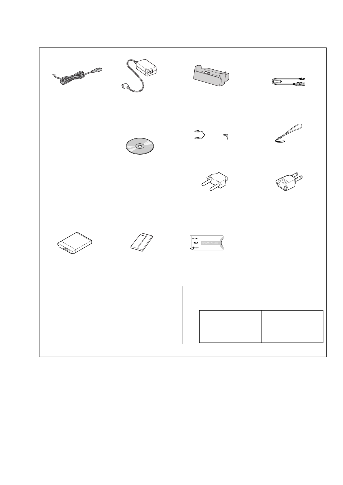
x Accessories
• AC-LM5 AC Adaptor (1)
• Power cord (mains lead) (1)
• UC-TA USB cradle (1)
• USB cable (1)
• NP-FT1 battery pack (1)
• A/V connecting cable (1)
• Wrist strap (1)
• “Memory Stick Duo” (32 MB) (1)
• Memory Stick Duo Adaptor (1)
• CD-ROM (USB driver SPVD-013) (1)
• Operating instructions (1)
CAUTION :
Danger of explosion if battery is incorrectly replaced.
Replace only with the same or equivalent type.
SAFETY-RELATED COMPONENT WARNING!!
COMPONENTS IDENTIFIED BY MARK 0 OR DOTTED LINE WITH
MARK 0 ON THE SCHEMATIC DIAGRAMS AND IN THE PARTS
LIST ARE CRITICAL TO SAFE OPERATION. REPLACE THESE
COMPONENTS WITH SONY PARTS WHOSE PART NUMBERS
APPEAR AS SHOWN IN THIS MANUAL OR IN SUPPLEMENTS
PUBLISHED BY SONY.
Design and specifications are subject to change
without notice.
ATTENTION AU COMPOSANT AYANT RAPPORT
À LA SÉCURITÉ!
LES COMPOSANTS IDENTIFÉS P AR UNE MARQUE 0 SUR LES
DIAGRAMMES SCHÉMA TIQUES ET LA LISTE DES PIÈCES SONT
CRITIQUES POUR LA SÉCURITÉ DE FONCTIONNEMENT. NE
REMPLACER CES COMPOSANTS QUE PAR DES PIÈSES SONY
DONT LES NUMÉROS SONT DONNÉS DANS CE MANUEL OU
DANS LES SUPPÉMENTS PUBLIÉS PAR SONY.
— 2 —
Page 3
Checking supplied accessories.
Make sure that the following accessories are supplied with your camcorder.
DSC-T1
Power cord (Main lead) (1)
(AUS model)
0
1-696-819-11
Power cord (Main lead) (1)
(AEP, E model)
0
1-769-608-11
Power cord (Main lead) (1)
(CH model)
0
1-782-476-13
Power cord (Main lead) (1)
(UK, HK model)
0
1-783-374-11
Power cord (Main lead) (1)
(JE model)
0
1-790-732-12
Power cord (Main lead) (1)
(J model)
0
1-791-637-13
Power cord (Main lead) (1)
(KR model)
0
1-776-985-11
Power cord (Main lead) (1)
(US, CND model)
0
1-790-107-22
NP-FT1 battery pack (1)
(not supplied)
AC-LM5 AC Adaptor (1)
(Except US, CND)
0
1-477-488-12
AC-LM5 AC Adaptor (1)
(US, CND)
0
1-477-488-21
CD-ROM
(USB Driver SPVD-013) (1)
(AEP, UK, E, HK, AUS, CH,
JE, KR model)
3-087-330-01
CD-ROM
(USB Driver SPVD-013 (I)) (1)
(US, CND, J model)
3-087-331-01
“Memory stick Duo” (1)
(MSA-M32A)
(not supplied)
UC-TA USB cradle (1)
1-817-742-11
A/V connecting cable (1)
1-824-111-11
2-pin conversion adaptor (1)
(JE model)
1-569-007-12
Memory stick Duo Adaptor(1)
(MSAC-M2)
(not supplied)
USB cable (1)
1-828-073-11
Wrist strap (1)
3-086-283-01
2-pin conversion adaptor (1)
(E model)
1-569-008-12
• Abbreviation
CND : Canadian model
AUS : Australian model
CH : Chinese model
HK : Hong Kong model
KR : Korea model
JE : Tourist model
J : Japanese model
Other accessories
3-085-733-01 MANUAL, INSTRUCTION SET (JAPANESE) (J)
3-085-733-11 MANUAL, INSTRUCTION SET (ENGLISH) (EXCEPT KR, J)
3-085-733-21 MANUAL, INSTRUCTION SET (FRENCH/GERMAN)
3-085-733-31 MANUAL, INSTRUCTION SET (SPANISH/PORTUGUESE)
3-085-733-41 MANUAL, INSTRUCTION SET (ITALIAN/DUTCH) (AEP)
3-085-733-51 MANUAL, INSTRUCTION SET (CHINESE) (E, HK, CH, JE)
3-085-733-61 MANUAL, INSTRUCTION SET
(RUSSIAN/SWEDISH) (AEP)
(CND, AEP)
(AEP, E, JE)
SAFETY CHECK-OUT
After correcting the original service problem, perform the following
safety checks before releasing the set to the customer.
1. Check the area of your repair for unsoldered or poorly-soldered
connections. Check the entire board surface for solder splashes
and bridges.
2. Check the interboard wiring to ensure that no wires are
"pinched" or contact high-wattage resistors.
3. Look for unauthorized replacement parts, particularly
transistors, that were installed during a previous repair. Point
them out to the customer and recommend their replacement.
4. Look for parts which, through functioning, show obvious signs
3-085-733-71 MANUAL, INSTRUCTION SET (ARABIC) (E)
3-085-733-81 MANUAL, INSTRUCTION SET (KOREAN) (JE, KR)
3-085-734-01 MANUAL, INSTRUCTION (for PC)(JAPANESE) (J)
Note :
The components identified by
mark 0 or dotted line with mark
0 are critical for safety.
Replace only with part number
specified.
Note :
Les composants identifiés par
une marque 0 sont critiques
pour la sécurité.
Ne les remplacer que par une
pièce portant le numéro spécifié.
of deterioration. Point them out to the customer and
recommend their replacement.
5. Check the B+ voltage to see it is at the values specified.
6. Flexible Circuit Board Repairing
• Keep the temperature of the soldering iron around 270˚C
during repairing.
• Do not touch the soldering iron on the same conductor of the
circuit board (within 3 times).
• Be careful not to apply force on the conductor when soldering
or unsoldering.
— 3 —
Page 4
DSC-T1
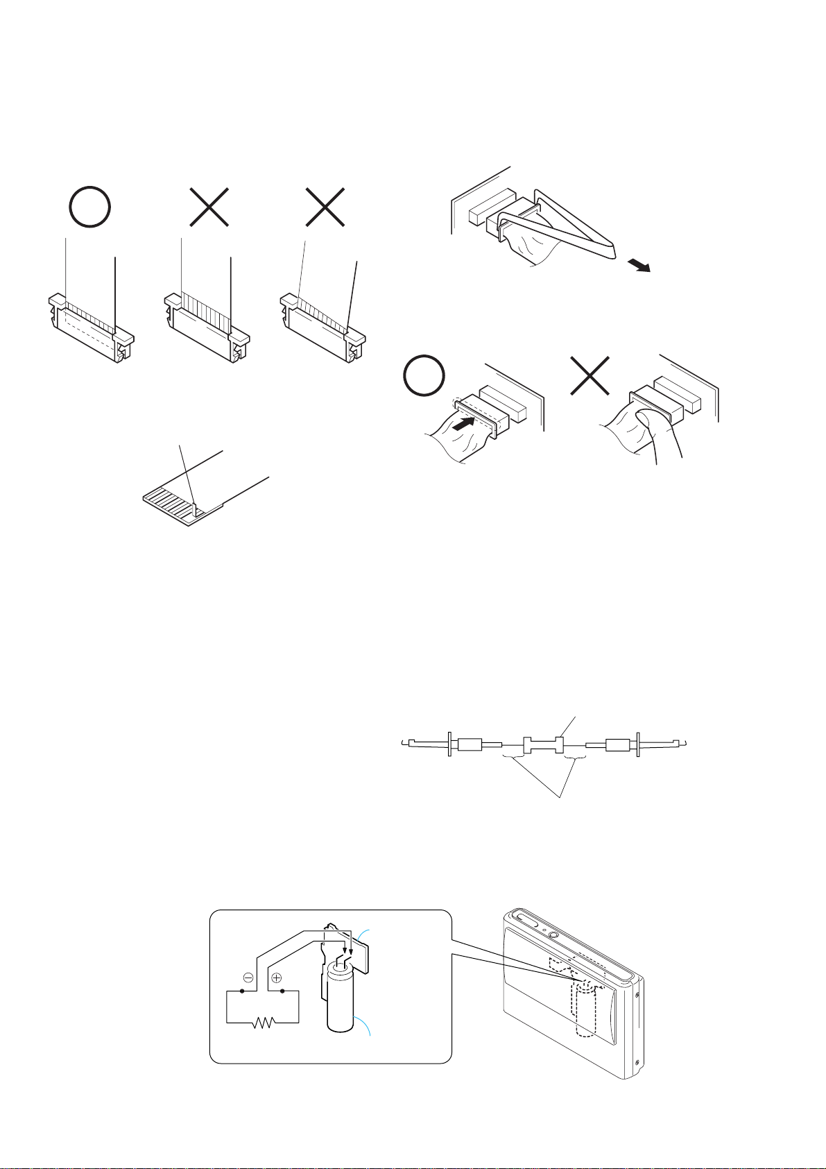
• NOTE FOR REPAIR
SELF-DIAGNOSIS FUNCTION
Make sure that the flat cable and flexible board are not cracked of
bent at the terminal.
Do not insert the cable insufficiently nor crookedly.
Cut and remove the part of gilt
which comes off at the point.
(Take care that there are
some pieces of gilt left inside)
When remove a connector, don't pull at wire of connector.
Be in danger of the snapping of a wire.
When installing a connector, don't press down at wire of connector.
Be in danger of the snapping of a wire.
[Discharging of the FLASH unit’s charging capacitor]
The charging capacitor of the FLASH unit is charged up to the
maximum 300 V potential.
There is a danger of electric shock by this high voltage when the
capacitor is handled by hand. The electric shock is caused by the
charged voltage which is kept without discharging when the main
power of the DSC-T1 is simply turned off. Therefore, the remaining
voltage must be discharged as described below.
Preparing the Short Jig
To preparing the short jig. a small clip is attached to each end of a
resistor of 1 kΩ /1 W (1-215-869-11)
Wrap insulating tape fully around the leads of the resistor to prevent
electrical shock.
Discharging the Capacitor
Short circuits between the positive and the negative terminals of
charged capacitor with the short jig about 10 seconds.
1 kΩ/1 W
Wrap insulating tape.
ST-86 B0ARD
Shorting jig
(1kΩ / 1w)
Capacitor
— 4 —
Page 5

[Description on Self-diagnosis Display]
Self-diagnosis display
• C: ss: ss
The contents which can be handled
by customer, are displayed.
• E: ss: ss
The contents which can be handled
by engineer, are displayed.
DSC-T1
Display Code
C:32:01
C:13:01
E:91:01
E:61:00 *1
E61:10 *1
Note : The error code is cleared if the battery is removed, except defective flash unit.
*1: The error display is given in two ways.
Turn off the main power then back on.
Replace the memory stick.
Format the memory stick with the DSC-T1.
Checking of flash unit or replacement of
flash unit.
Checking of lens drive circuit
Countermeasure
Trouble with hardware.
• The type of memory stick that cannot be
used by this machine, is inserted.
• Data is damaged.
• Unformatted memory stick is inserted.
Abnormality when flash is being
charged.
When failed in the focus initialization.
Cause
Caution Display During Error
SYSTEM ERROR
MS ERROR
Flash LED
Flash display
Flashing at 3.2 Hz
—
— 5 —
Page 6

DSC-T1
9-876-280-41
Sony EMCS Co.
— 6 —
2004C1600-1
©2004.3
Published by DI CS Strategy Div.
Page 7
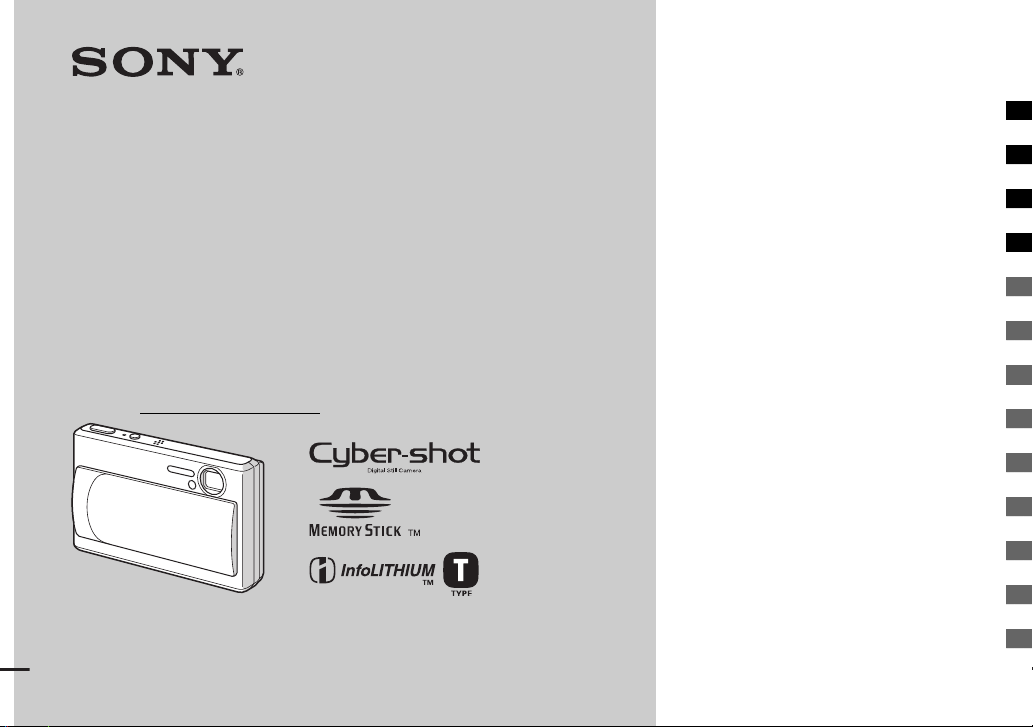
3-085-733-11(1)
Getting started_________________________
Digital Still Camera
Operating Instructions
Before operating the unit, please read this manual thoroughly, and
retain it for future reference.
Owner’s Record
The model and serial numbers are located on the bottom. Record the
serial number in the space provided below. Refer to these numbers
whenever you call upon your Sony dealer regarding this product.
Model No. DSC-T1
Serial No.
DSC-T1
DSC-T1
© 2003 Sony Corporation
© 2003 Sony Corporation
Shooting still images ___________________
Viewing still images____________________
Deleting still images ___________________
Before advanced operations______________
Advanced still image shooting ____________
Advanced still image viewing _____________
Still image editing _______________________
Enjoying movies ________________________
Enjoying images on your computer
Troubleshooting ________________________
Additional information____________________
Index __________________________________
__________
Page 8

WARNING
To prevent fire or shock hazard, do
not expose the unit to rain or
moisture.
For the Customers in the U.S.A.
This symbol is intended to alert
the user to the presence of
uninsulated “dangerous
voltage” within the product’s
enclosure that may be of
sufficient magnitude to
constitute a risk of electric
shock to persons.
This symbol is intended to alert
the user to the presence of
important operating and
maintenance (servicing)
instructions in the literature
accompanying the appliance.
If you have any questions about this product,
you may call:
Sony Customer Information Center
1-800-222-SONY (7669)
The number below is for the FCC related matters
only.
Regulatory Information
Declaration of Conformity
Trade Name: SONY
Model No.: DSC-T1
Responsible Party: Sony Electronics Inc.
Address: 680 Kinderkamack Road,
Telephone No.: 201-930-6972
This device complies with Part 15 of the
FCC Rules. Operation is subject to the
following two conditions: (1) This device
may not cause harmful interference, and
(2) this device must accept any interference
received, including interference that may
cause undesired operation.
Note:
Model DSC-T1 is to be used with USB cradle
Model UC-TA and AC Adaptor Model ACLM5.
CAUTION
You are cautioned that any changes or
modifications not expressly approved in this
manual could void your authority to operate this
equipment.
Oradell, NJ 07649 U.S.A.
Note:
This equipment has been tested and found to
comply with the limits for a Class B digital
device, pursuant to Part 15 of the FCC Rules.
These limits are designed to provide reasonable
protection against harmful interference in a
residential installation. This equipment generates,
uses, and can radiate radio frequency energy and,
if not installed and used in accordance with the
instructions, may cause harmful interference to
radio communications. However, there is no
guarantee that interference will not occur in a
particular installation. If this equipment does
cause harmful interference to radio or television
reception, which can be determined by turning
the equipment off and on, the user is encouraged
to try to correct the interference by one or more of
the following measures:
— Reorient or relocate the receiving antenna.
— Increase the separation between the
equipment and receiver.
— Connect the equipment into an outlet on a
circuit different from that to which the
receiver is connected.
— Consult the dealer or an experienced radio/
TV technician for help.
The shielded interface cable must be used with
the equipment in order to comply with the limits
for a digital device pursuant to Subpart B of Part
15 of FCC Rules.
2
Page 9

For the Customers in the U.S.A.
and Canada
RECYCLING LITHIUM-ION
BATTERIES
Lithium-Ion batteries are
recyclable.
You can help preserve our
environment by returning your
used rechargeable batteries to
the collection and recycling location nearest
you.
For more information regarding recycling of
rechargeable batteries, call toll free
1-800-822-8837, or visit
http://www.rbrc.org/
Caution:Do not handle damaged or leaking
Lithium-Ion batteries.
CAUTION
TO PREVENT ELECTRIC SHOCK, MATCH
WIDE BLADE OF PLUG TO WIDE SLOT,
FULLY INSERT.
Never expose the battery pack to temperature
above 60°C (140°F), such as in a car parked in the
sun or under direct sunlight.
Notice for the customers in the
United Kingdom
A moulded plug complying with BS 1363 is fitted
to this equipment for your safety and
convenience.
Should the fuse in the plug supplied need to be
replaced, a fuse of the same rating as the supplied
one and approved by ASTA or BSI to BS 1362,
(i.e., marked with or mark) must be used.
If the plug supplied with this equipment has a
detachable fuse cover, be sure to attach the
fuse cover after you change the fuse. Never
use the plug without the fuse cover. If you
should lose the fuse cover, please contact your
nearest Sony service station.
Attention for the Customers in
Europe
This product has been tested and found compliant
with the limits sets out in the EMC Directive for
using connection cables shorter than 3 meters
(9.8 feet).
Attention
The electromagnetic field at the specific
frequencies may influence the picture and sound
of this camera.
Notice
If static electricity or electromagnetism causes
data transfer to discontinue midway (fail), restart
the application or disconnect and connect the
USB cable again.
“Memory Stick”
N50
For the Customers in the U.S.A.
THIS DEVICE COMPLIES WITH PART 15
OF THE FCC RULES. OPERATION IS
SUBJECT TO THE FOLLOWING TWO
CONDITIONS:
(1) THIS DEVICE MAY NOT CAUSE
HARMFUL INTERFERENCE, AND
(2) THIS DEVICE MUST ACCEPT ANY
INTERFERENCE RECEIVED,
INCLUDING INTERFERENCE THAT MAY
CAUSE UNDESIRED OPERATION.
For the Customers in Canada
THIS CLASS B DIGITAL APPARATUS
COMPLIES WITH CANADIAN ICES-003.
Notice
Certain countries and regions may regulate
disposal of the battery used to power this product.
Please consult with your local authority.
3
Page 10

Before using your camera
Trial recording
Before you record one-time events, you may want
to make a trial recording to make sure that the
camera is working correctly.
No compensation for contents of the
recording
Contents of the recording cannot be compensated
for if recording or playback is not possible due to
a malfunction of your camera or recording media,
etc.
Back up recommendation
To avoid the potential risk of data loss, always
copy (back up) data to a disk.
Notes on image data compatibility
• This camera conforms with the Design rule for
Camera File system universal standard
established by the JEITA (Japan Electronics
and Information Technology Industries
Association).
• Playback of images recorded with your camera
on other equipment and playback of images
recorded or edited with other equipment on
your camera are not guaranteed.
Precaution on copyright
Television programs, films, video tapes, and other
materials may be copyrighted. Unauthorized
recording of such materials may be contrary to
the provision of the copyright laws.
4
Do not shake or strike the camera
In addition to malfunctions and inability to record
images, this may render the “Memory Stick Duo”
unusable or image data breakdown, damage or
loss may occur.
LCD screen, LCD finder (only models
with an LCD finder) and lens
• The LCD screen and the LCD finder are
manufactured using extremely high-precision
technology so over 99.99% of the pixels are
operational for effective use. However, there
may be some tiny black points and/or bright
points (white, red, blue or green in color) that
constantly appear on the LCD screen and the
LCD finder. These points are normal in the
manufacturing process and do not affect the
recording in any way.
• Be careful when placing the camera near a
window or outdoors. Exposing the LCD screen,
the finder or the lens to direct sunlight for long
periods may cause malfunctions.
• Do not press the LCD screen hardly. The screen
may be uneven and that may cause a
malfunction.
• Do not press the lens portion hard, or it may
cause the malfunction of the lens.
• Images may be trailed on the LCD screen in a
cold location. This is not a malfunction.
Carl Zeiss lens
This camera is equipped with a Carl Zeiss lens
which is capable of reproducing sharp images
with excellent contrast.
The lens for this camera has been produced
under a quality assurance system certified by
Carl Zeiss in accordance with the quality
standards of Carl Zeiss in Germany.
Clean the flash surface before use
The heat of flash emission may cause dirt on the
flash surface to become discolored or to stick to
the flash surface, resulting in insufficient light
emission.
Do not get the camera wet
When taking pictures outdoors in the rain or
under similar conditions, be careful not to get the
camera wet. If moisture condensation occurs, see
page 108 and follow the instructions on how to
remove it before using the camera.
Do not expose the camera to sand or
dust
Using the camera in sandy or dusty locations may
cause malfunction.
Do not aim the camera at the sun or
other bright light
This may cause irrecoverable damage to your
eyes. Or it may cause the malfunction of your
camera.
Page 11

Note on the camera locations
Do not use the camera near a location that
generates strong radio wave or emits radiation.
The camera may not be able to record or play
back properly.
The pictures used in this manual
The photographs used as examples of pictures in
this manual are reproduced images, and are not
actual images shot using this camera.
Trademarks
• “Memory Stick Duo” and
are trademarks of Sony Corporation.
• “Memory Stick PRO Duo” and
are trademarks of
Sony Corporation.
• “MagicGate Memory Stick Duo” is a
trademark of Sony Corporation.
• “Memory Stick,” and “MagicGate
Memory Stick” are trademarks of Sony
Corporation.
• “Memory Stick PRO” and
are trademarks of Sony Corporation.
• “MagicGate” and are
trademarks of Sony Corporation.
• “InfoLITHIUM” is a trademark of Sony
Corporation.
• Microsoft and Windows are registered
trademarks of the U.S. Microsoft Corporation
in the United States and other countries.
• Macintosh, Mac OS and QuickTime are
trademarks or registered trademarks of Apple
Computer, Inc.
• Pentium is a trademark or a registered
trademark of Intel Corporation.
• In addition, system and product names used in
this manual are, in general, trademarks or
registered trademarks of their respective
developers or manufacturers. However, the ™
or ® marks are not used in all cases in this
manual.
5
Page 12

Table of contents
Before using your camera ......................... 4
Identifying the parts ................................. 8
Camera.................................................. 8
USB cradle.......................................... 10
Connecting and disconnecting your
camera ............................................10
Getting started
Charging the battery pack .......................11
Using the AC Adaptor ............................ 15
Using your camera abroad ......................15
Turning on/off your camera ....................16
How to use the control button................. 16
Setting the date and time......................... 17
Shooting still images
Inserting and removing a “Memory Stick
Duo” ............................................... 19
Setting the still image size ......................20
Image size ............................................... 21
Basic still image shooting
— Using auto adjustment mode .....22
Checking the last image you shot
— Quick Review............................ 24
Indicators on the LCD screen during
shooting .......................................... 25
Using the zoom feature....................... 25
Shooting close-ups
— Macro......................................... 27
Using the self-timer ............................ 28
6
Selecting a flash mode ....................... 29
Inserting the date and time on a still
image.............................................. 30
Shooting according to scene conditions
— Scene Selection ......................... 32
Viewing still images
Viewing images on the LCD screen of your
camera ............................................ 35
Viewing images on a TV screen............. 37
Deleting still images
Deleting images ...................................... 39
Formatting a “Memory Stick Duo”........ 41
Before advanced operations
How to setup and operate your
camera ............................................ 43
Changing the menu settings ............... 43
Changing the items on the
Setup screen ................................... 44
Deciding the still image quality.............. 44
Creating or selecting a folder ................. 45
Creating a new folder ......................... 45
Changing the recording folder ........... 46
Advanced still image
shooting
Choosing an auto focus method .............. 47
Choosing a focus range finder frame
— AF range finder..........................47
Choosing a focus operation
— AF Mode.................................... 48
Setting the distance to the subject
— Focus preset ...............................49
Adjusting the exposure
— EV adjustment ...........................50
Displaying a histogram .......................51
Selecting the metering mode................... 52
Shooting three images with the exposure
shifted — Exposure Bracket...........52
Adjusting color tones
— White Balance ........................... 54
Adjusting the flash level
— Flash Level ................................ 55
Shooting images continuously
— Burst ..........................................55
Shooting in Multi Burst mode
— Multi Burst.................................56
Shooting still images for e-mail
— E-Mail........................................57
Shooting still images with audio files
— Voice..........................................58
Adding special effects
— Picture Effect .............................58
Page 13

Advanced still image viewing
Selecting the folder and playing back
images
— Folder.........................................60
Enlarging a portion of a still image.........61
Enlarging an image
— Playback zoom...........................61
Recording an enlarged image
— Trimming ...................................62
Playing back successive images
— Slide Show.................................62
Rotating still images
— Rotate.........................................63
Playing back images shot in Multi Burst
mode ............................................... 64
Playing back continuously ..................64
Playing back frame by frame
— Jog playback ..............................65
Still image editing
Protecting images
— Protect........................................66
Changing image size
— Resize.........................................67
Choosing images to print
— Print (DPOF) mark ....................68
Enjoying movies
Shooting movies ..................................... 70
Viewing movies on the LCD screen ....... 71
Deleting movies ...................................... 72
Editing movies........................................ 73
Cutting movies.................................... 74
Deleting unnecessary portions
of movies........................................ 74
Enjoying images on your
computer
Copying images to your computer
— For Windows users.................... 75
Copying images to your computer
— For Macintosh users .................. 86
Troubleshooting
Troubleshooting...................................... 88
Warnings and messages .......................... 97
Self-diagnosis display............................. 99
Additional information
Number of images that can be saved or
shooting time.................................100
Menu items............................................102
Setup items ............................................106
Precautions ............................................108
On “Memory Stick” ..............................109
On “InfoLITHIUM” battery pack .........111
Specifications ........................................112
The LCD screen ....................................114
Index
Index......................................................118
7
Page 14
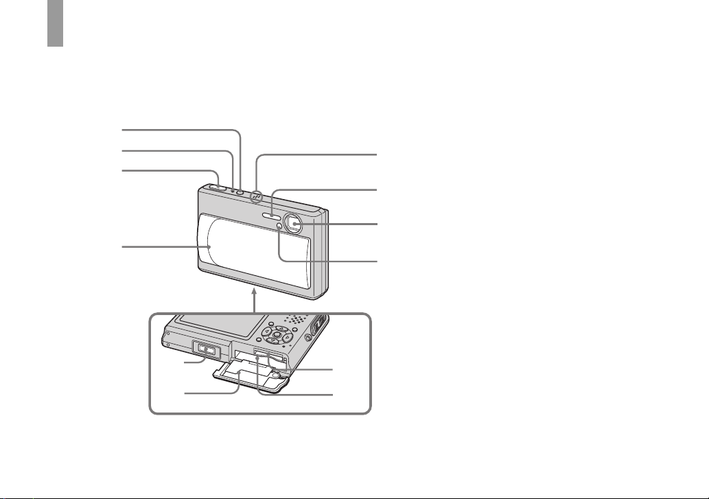
Identifying the parts
See the pages in parentheses for details of operation.
Camera
1
2
3
4
5
6
7
8
9
q;
qa
qs
A POWER button (16)
B POWER lamp (16)
C Shutter button (22)
D Lens cover (16)
E Multi connector (13, 15)
F Battery/“Memory Stick Duo”
cover
G “Memory Stick Duo” insertion
slot (19)
H Battery insertion slot (11)
I Microphone
J Flash (29)
K Lens
L Self-timer lamp (28)/
AF illuminator (30, 106)
8
Page 15
1
2
3
4
5
6
7
8
9
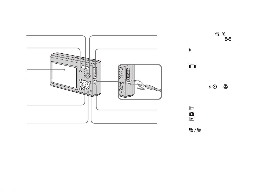
Attaching the
strap
0
qa
qs
A For shooting: Zoom (W/T) button
(25)
For viewing: / (Playback
zoom) button (61)/ (Index)
button (36)
B /CHG lamp (orange) (12, 29)
C LCD screen
D MENU button (43, 102)
E (Display/LCD backlight on/
off) button (25)
F Control button
Menu on: v/V/b/B/z (16)
Menu off: / /7/ (29/28/24/27)
G RESET button (88)
H Speaker
I Mode switch (17, 102)
: To shoot movies
: To shoot still images
: To view or edit images
J Hook for wrist strap
K (Image Size/Delete) button
(20, 39)
L Access lamp (19)
9
Page 16
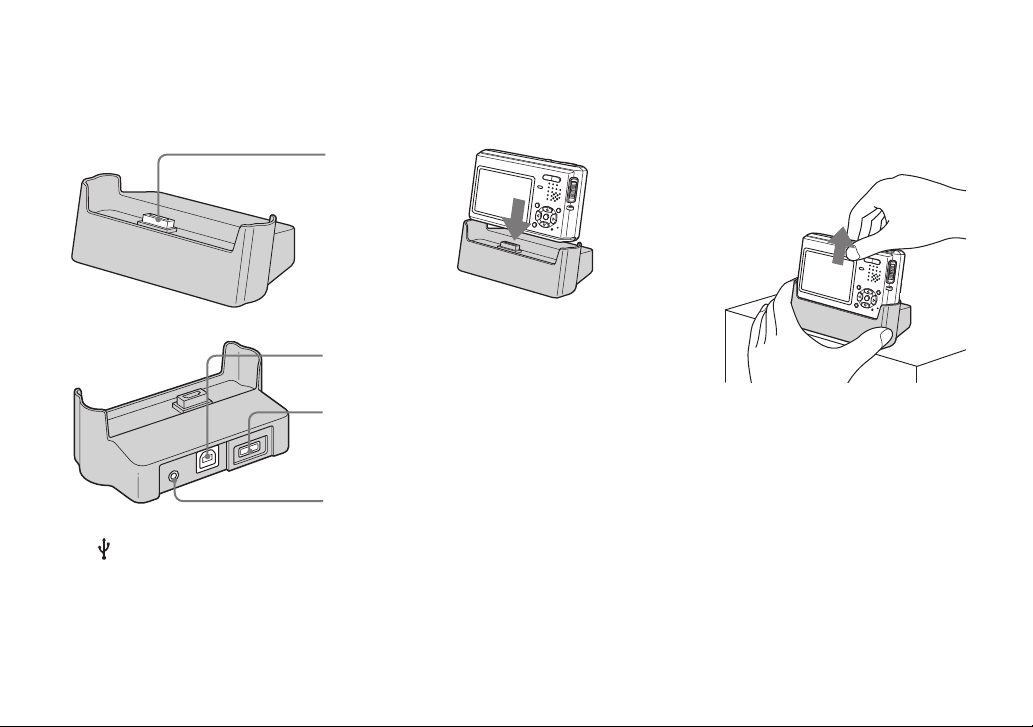
USB cradle
4
Connecting and disconnecting your camera
This is used when charging the battery pack
or connecting the camera to a TV, etc.
1
2
3
A Camera connector
B (USB) jack (79)
C DC IN jack (11)
D A/V OUT (MONO) jack (37)
How to connect
Connect the camera as illustrated.
• Make sure the camera is securely connected to
the USB cradle.
How to disconnect
Grasp the camera and the USB cradle
(supplied) as illustrated and disconnect the
camera.
• Be sure to turn off the camera before you
connect the camera to the USB cradle or
disconnect the camera from the USB cradle.
• Do not disconnect the camera from the
USB cradle during the USB connection,
as the data may be corrupted. To cancel
the USB connection, see P on page 80
(Windows) or 1 on page 86
(Macintosh).
10
Page 17
Getting started
Charging the battery pack
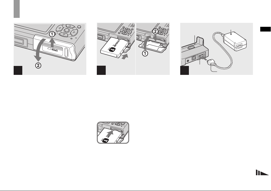
1
, Open the battery/“Memory
Stick Duo” cover.
Slide the cover in the direction of the arrow.
• Be sure to turn off your camera when
charging the battery pack (page 16).
• Your camera operates with the
“InfoLITHIUM” NP-FT1 battery pack (T type)
(supplied). You can use only T type battery
pack (page 111).
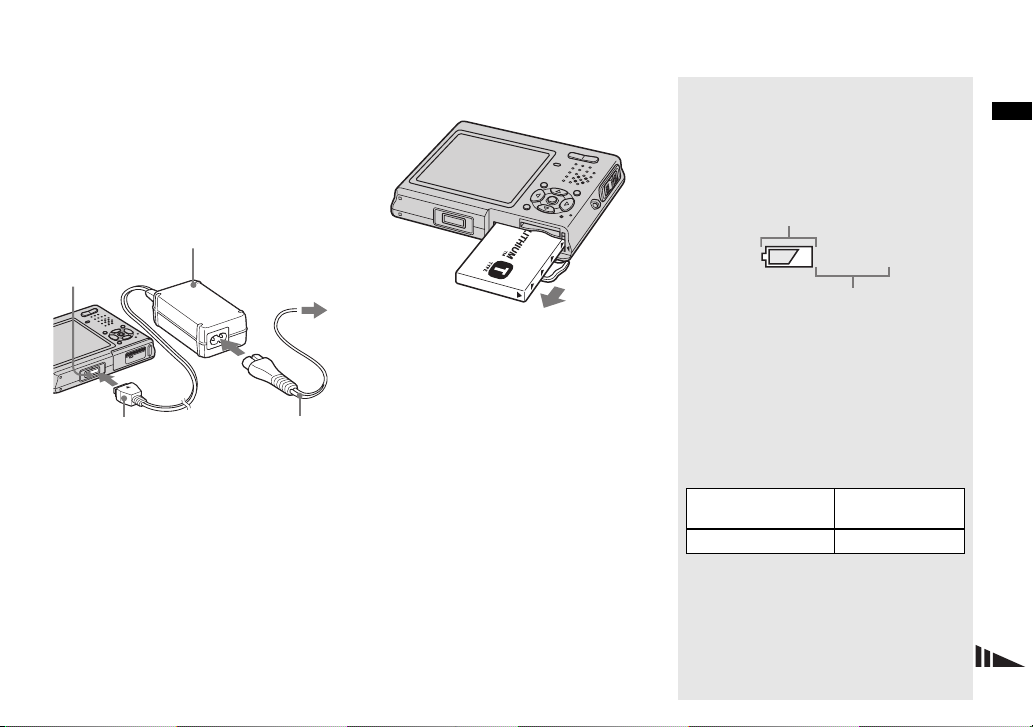
2
, Install the battery pack, then
close the battery/“Memory
Stick Duo” cover.
Make sure the battery pack is firmly
inserted all the way, then close the cover.
Battery insertion slot
Insert the battery pack so
that the v marks on the
side of the battery pack
face the same direction
as the v mark on the
battery insertion slot.
• Be careful not to drop the battery pack when
installing it.
USB cradle
DC IN jack
3
AC Adaptor
DC plug
, Connect the AC Adaptor
(supplied) to the DC IN jack of
the USB cradle (supplied).
Connect the plug with the v mark facing
up.
• Do not short the DC plug of the AC Adaptor
with a metallic object, as this may cause
malfunction.
Getting started
11
Page 18

4
Power cord
(mains lead)
2 To a wall outlet
(wall socket)
1
Disconnecting the AC Adaptor from
the USB cradle
Hold the DC plug itself and the USB cradle
as illustrated and disconnect the cable.
5
, Connect the power cord (mains
lead) to the AC Adaptor and to
a wall outlet (wall socket).
12
, Connect the camera to the USB
cradle.
Connect the camera as illustrated.
The /CHG lamp lights up when charging
begins, and goes off when charging is
completed.
/CHG
/CHG lamp
• Make sure the camera is securely connected to
the USB cradle.
DC plug
Page 19
To charge the battery pack only
using the AC Adaptor
You can charge the battery pack without the
USB cradle, such as during your travels.
Connect the DC plug of the AC Adaptor to
the camera with v mark facing as
illustrated.
AC Adaptor
Multi
connector
To a wall outlet
(wall socket)
3
To remove the battery pack
Battery remaining indicator
The battery remaining indicator on the
upper left side of the LCD screen shows the
remaining shooting/viewing time and the
battery remaining charge.
Remaining indicator
60min
Remaining time
Getting started
1
DC plug
• Be sure to turn off your camera when
charging the battery pack (page 16).
• When placing the camera, make sure the LCD
screen is facing up.
• After charging the battery pack, disconnect the
AC Adaptor both from the multi connector of
the camera and from a wall outlet (wall socket).
2
Power cord
(mains lead)
Open the battery/“Memory Stick Duo”
cover, then hold the camera so that it faces
downward and remove the battery pack.
• Be careful not to drop the battery pack when
removing it.
• The displayed time remaining may not be
correct under certain circumstances or
conditions.
Charging time
Approximate time to charge a completely
discharged battery pack using the AC
Adaptor at a temperature of 25°C (77°F).
Battery pack
NP-FT1 (supplied) Approx. 150
Charging time
(min.)
13
Page 20
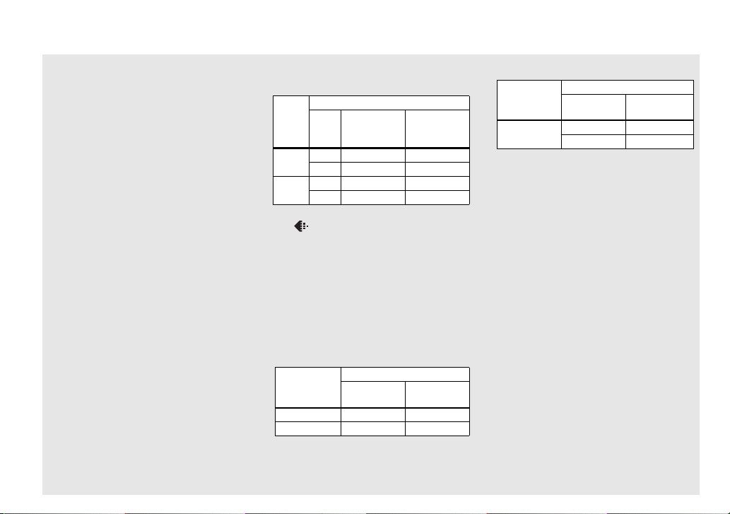
Number of images and battery
life that can be recorded/
viewed
The tables show the approximate number of
images and the battery life that can be
recorded/viewed when you shoot images in
normal mode with a fully charged battery
pack at a temperature of 25°C (77°F). The
numbers of images that can be recorded or
viewed take into account changing the
“Memory Stick Duo” as necessary. Note
that the actual numbers may be less than
indicated depending on the conditions of
use.
Shooting still images
Under the average conditions
NP-FT1 (supplied)
Image
LCD
size
5M
VGA
1)
Shooting in the following situations:
– (P.Quality) is set to [Fine]
– Shooting one time every 30 seconds
– The zoom is switched alternately between
the W and T ends
– The flash strobes once every two times
– The power turns on and off once every ten
times
– [AF Mode] is set to [Single] on the Setup
screen
No. of
back-
images
light
On Approx. 170 Approx. 85
Off Approx. 200 Approx. 100
On Approx. 170 Approx. 85
Off Approx. 200 Approx.100
Viewing still images
Image size
5M Approx. 2600 Approx. 130
VGA Approx. 2800 Approx. 140
2)
Viewing single images in order at about three
second intervals
NP-FT1 (supplied)
No. of
images
1)
Battery life
(min.)
2)
Battery life
(min.)
Shooting movies
3)
NP-FT1 (supplied)
LCD
backlight
Continuous
shooting
3)
Shooting movies continuously with the image
size [160]
• The number of images and the battery life that
can be recorded/viewed are decreased under the
following conditions:
– The surrounding temperature is low
– The flash is used
– The camera has been turned on and off many
times
– The zoom is used frequently
– [LCD Backlight] is set to [Bright] on the
Setup screen
– The battery power is low.
The battery capacity decreases as you use it
more and more and as time passes
(page 111).
– [AF Mode] is set to [Monitor] or [Cont] on
the Setup screen
On Approx. 80
Off Approx. 100
Battery life
(min.)
14
Page 21
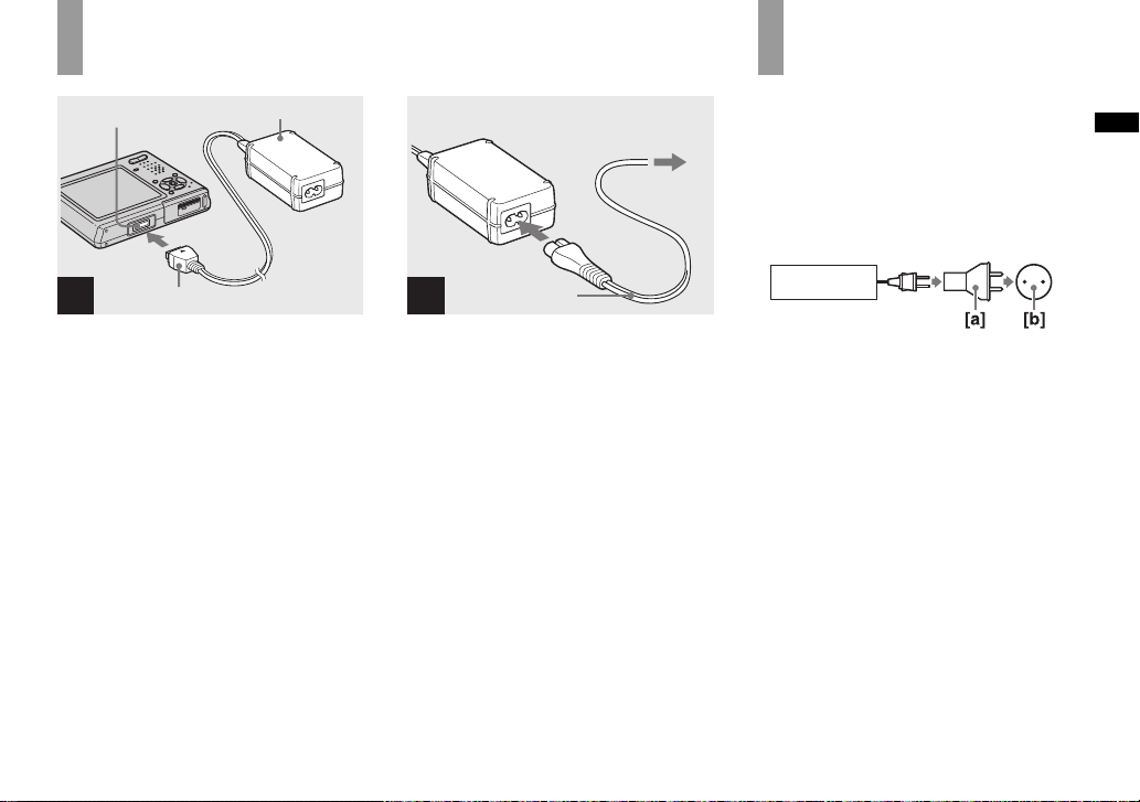
Using the AC Adaptor
Multi connector
1
DC plug
AC Adaptor
2
Power cord
(mains lead)
2 To wall outlet
(wall socket)
1
Using your camera
abroad
Power sources
You can use your camera in any country or
region with the AC Adaptor (supplied)
within 100 V to 240 V AC, 50/60 Hz. Use a
commercially available AC plug adaptor
[a], if necessary, depending on the design of
the wall outlet (wall socket) [b].
AC-LM5
Getting started
, Connect the AC Adaptor
(supplied) to the multi
connector of the camera.
When placing the camera, make sure the
LCD screen is facing up.
Connect the plug with the v mark facing
up.
• Connect the AC Adaptor to an easily accessible
wall outlet (wall socket) close by. If any trouble
occurs while using the adaptor, immediately
shut off the power by disconnecting the plug
from the wall outlet (wall socket).
, Connect the power cord (mains
lead) to the AC Adaptor and
then to a wall outlet (wall
socket).
• After using the AC Adaptor, disconnect it both
from the multi connector of the camera and
from a wall outlet (wall socket).
• The set is not disconnected from the AC power
source (mains) as long as it is connected to the
wall outlet (wall socket) even if the set itself has
been turned off.
• Do not use an electronic transformer (travel
converter), as this may cause a malfunction.
15
Page 22
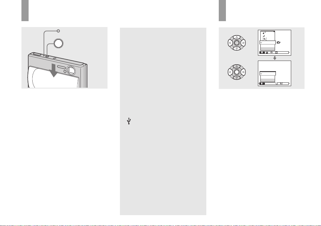
Turning on/off your camera
POWER lamp
POWER button
, Slide the lens cover in the
direction of arrow or press the
POWER button.
The POWER lamp (green) lights up and the
power is on. When you turn on your camera
for the first time, the Clock Set screen
appears (page 17).
Turning off the power
Slide the lens cover in the opposite direction
of the arrow or press the POWER button
again. The POWER lamp goes out, and the
camera turns off.
• If you open the lens cover too quickly, the
camera might not turn on. If this happens, close
the cover and then open it again more slowly.
• When opening the lens cover, be careful
not to touch the lens.
16
Auto power-off function
If you do not operate the camera for about
three minutes during shooting or viewing
or when performing the Setup, the
camera turns off automatically to prevent
wearing down the battery. The auto
power-off function only operates when
the camera is operating using a battery
pack. The auto power-off function also
will not operate in the following
circumstances.
• When viewing movies
• When playing back a slide show
• When a connector is plugged into the
(USB) jack or the A/V OUT
(MONO) jack with the camera
connected to the USB cradle
How to use the
control button
Program
Auto
Camera
WB
ISO
FINE
Fine
Standard
P.Quality
M
Mode BRK
To change the current settings of the
camera, bring up the menu or the Setup
screen (page 44), and use the control button
to make the changes.
For each item, press v/V/b/B to select the
desired value, then press z or v/V/b/B to
make the setting.
PFX
Page 23
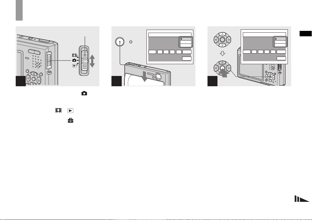
Setting the date and time
Mode switch
1
, Set the mode switch to .
• You can also carry out this operation when the
mode switch is set to or .
• To change the date and time on the Setup
screen, select [Clock Set] in (Setup 2)
(pages 44 and 107), and perform the procedure
from step 3.
2
POWER button
POWER
Clock Set
2003
/:
/
12 00
1 1
AM
Y/M/D
M/D/Y
D/M/Y
OK
Cancel
2
, Slide the lens cover or press
the POWER button to turn on
the camera.
The POWER lamp (green) lights up and the
Clock Set screen appears on the LCD
screen.
Clock Set
2003
/
/:
1 1
12 00
AM
Y/M/D
M/D/Y
D/M/Y
OK
Cancel
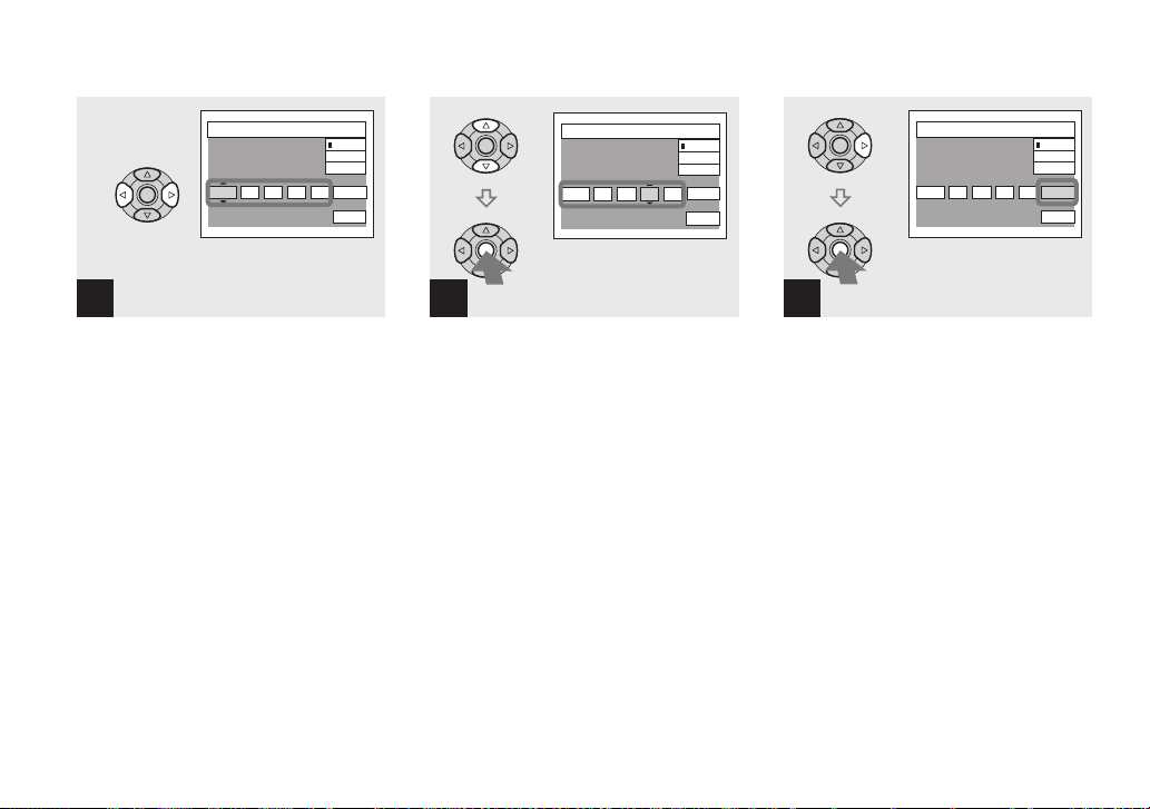
3
, Select the desired date display
format with v/V on the control
button, then press z.
Select from [Y/M/D] (year/month/day),
[M/D/Y] (month/day/year) or [D/M/Y]
(day/month/year).
• If the rechargeable button battery (page 109),
which provides the power for saving the time
data, ever becomes low, the Clock Set screen
will appear again. When this happens, reset the
date and time, by starting from step 3 above.
Getting started
17
Page 24
Clock Set
2003
/:
/
12 00
1 1
AM
Y/M/D
M/D/Y
D/M/Y
OK
Cancel
Clock Set
2004
/
10 00
/:
1 1
AM
Y/M/D
M/D/Y
D/M/Y
OK
Cancel
Clock Set
2004
/:
/
10 30
1 1
AM
Y/M/D
M/D/Y
D/M/Y
OK
Cancel
4
, Select the year, month, day,
hour or minute item you want
to set with b/B on the control
button.
The item to be set is indicated with v/V.
18
5
, Set the numeric value with v/V
on the control button, then
press z to enter it.
After entering the number, v/V moves to
the next item. Repeat steps
all of the items are set.
• If you selected [D/M/Y] in step 3, set the time
on a 24-hour cycle.
• Midnight is indicated as 12:00 AM, and noon
as 12:00 PM.
4 and 5 until
6
, Select [OK] with B on the
control button, then press z.
The date and time are entered and the clock
starts to keep time.
• To cancel the date and time setting, select
[Cancel] with v/V/b/B on the control button,
then press z.
Page 25

Shooting still images
Inserting and removing a “Memory Stick Duo”
Shooting still images
1
, Open the battery/“Memory
Stick Duo” cover.
Slide the cover in the direction of the arrow.
• When using this camera, the “Memory
Stick Duo” Adaptor (supplied) is not
necessary.
• Be careful not to drop the battery pack when
opening or closing the battery/“Memory Stick
Duo” cover.
• For details on “Memory Stick Duo,” see
page 109.
2
Terminal side
, Insert the “Memory Stick Duo.”
Insert a “Memory Stick Duo” all the way in
until it clicks as illustrated.
• When inserting a “Memory Stick Duo,” make
sure of the direction and insert it all the way to
the connector. If the “Memory Stick Duo” is
not inserted correctly, you may not be able to
record or display images with the “Memory
Stick Duo.” And also it may result in
malfunction of both the camera and “Memory
Stick Duo.”
3
Access lamp
, Close the battery/“Memory
Stick Duo” cover.
To remove a “Memory Stick Duo”
Open the battery/“Memory Stick Duo”
cover, then push the “Memory Stick Duo”
to pop it out.
• Whenever the access lamp is lit, the
camera is recording or reading an
image. Never open the battery/“Memory
Stick Duo” cover or turn off the power at
this time. The data may be corrupted.
19
Page 26
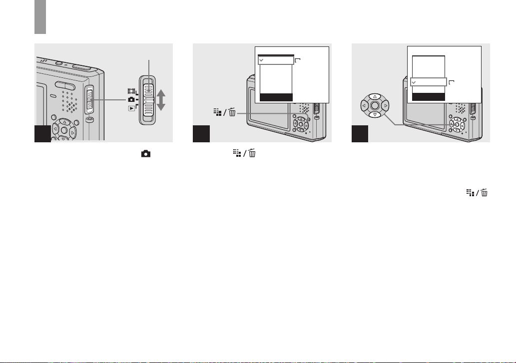
Setting the still image size
Mode switch
1
, Set the mode switch to , and
turn on the power.
5M
5M
3:2
3M
1M
VGA
Image Size
2
, Press (Image Size).
The Image Size setup appears.
• For details on the image size, see page 21.
5M
3:2
3M
1M
VGA
Image Size
1M
3
, Select the desired image size
with v/V on the control button.
The image size is set.
When the setting is complete, press
(Image Size) so that the Image Size setup
disappears from the LCD screen.
• The image size selected here is maintained even
when the power is turned off.
20
Page 27

Image size
You can choose image size (number of
pixels) and image quality (compression
ratio) based on the kind of images you want
to shoot. The larger you make the image
size and the higher you make the image
quality, the better your image, but also the
larger the amount of data needed to preserve
your image. This means you can save fewer
images in your “Memory Stick Duo.”
Choose an image size and quality
appropriately for the kind of images you
want to shoot.
• When images recorded using earlier Sony
models are played back on this camera, the
display may differ from the actual image size.
• When the images are viewed on the LCD
screen of the camera, they all look the same
size.
• Number of shooting images can differ from
these values according to shooting conditions.
• When the number of remaining shooting
images is greater than 9999, the “>9999”
indicator appears on the LCD screen.
• You can resize the images later (Resize
function, see page 67).
Image size Usage guidelines
1)
5M
(2592×1944)
3:22) (2592×1728)
Large
• For saving important images, printing in A4 size or
printing A5 size high density images
3M (2048×1536)
1M (1280×960) • For printing in postcard size
VGA (640×480)
1)
The factory setting is [5M]. It is the highest image quality on this camera.
2)
Images are recorded in the same 3:2 aspect ratio as photograph printing paper or postcards, etc.
Small
• For recording a larger number of images
• For attaching images to e-mail or creating home pages
The number of images that can be saved in a “Memory Stick Duo”
The number of images that can be saved in Fine (Standard)4) mode are shown below.
(Units: number of images)
Capacity
Image size
5M 6 (11) 12 (23) 25 (48) 51 (96) 92 (174) 188 (354)
3:2 6 (11) 12 (23) 25 (48) 51 (96) 92 (174) 188 (354)
3M 10 (18) 20 (37) 41 (74) 82 (149) 148 (264) 302 (537)
1M 24 (46) 50 (93) 101 (187) 202 (376) 357 (649) 726 (1320)
VGA 97 (243) 196 (491) 394 (985) 790 (1975) 1428 (3571) 2904 (7261)
3)
When [Mode] (REC Mode) is set to [Normal]
For the number of images that can be saved in other modes, see page 100.
4)
For more information about the image quality (compression ratio), see page 44.
16MB 32MB 64MB 128MB MSX-M256 MSX-M512
Shooting still images
3)
21
Page 28
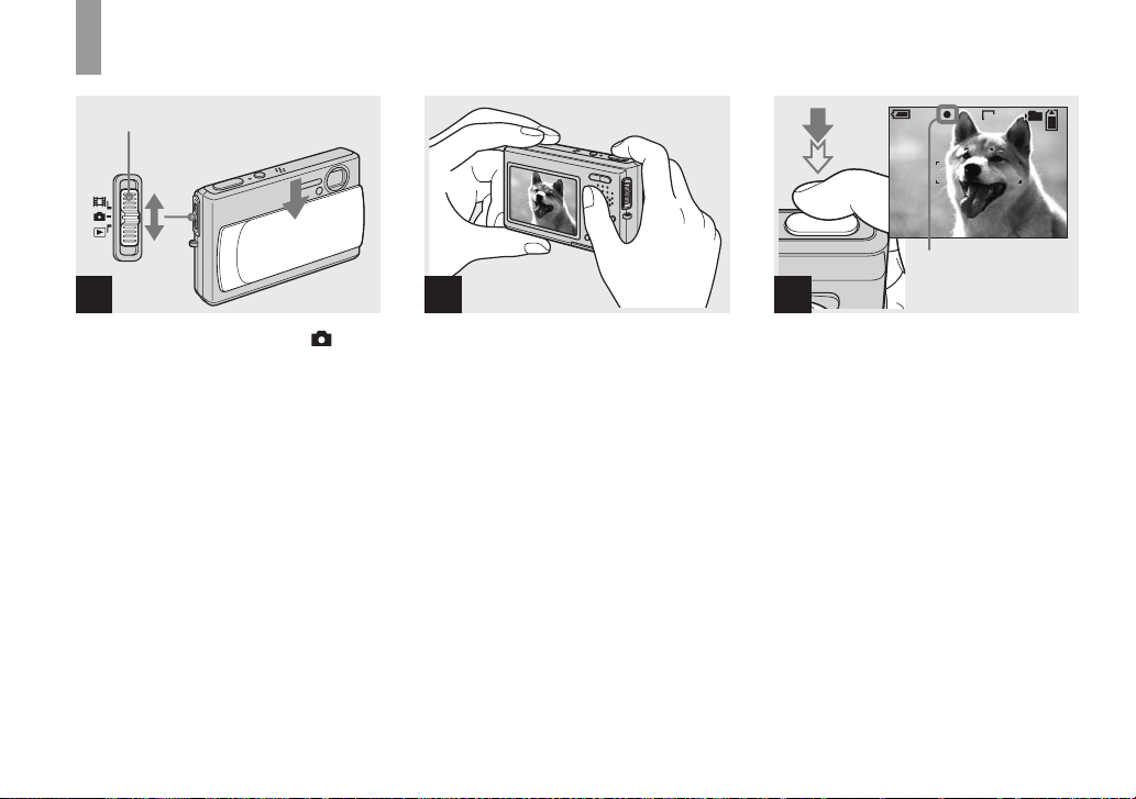
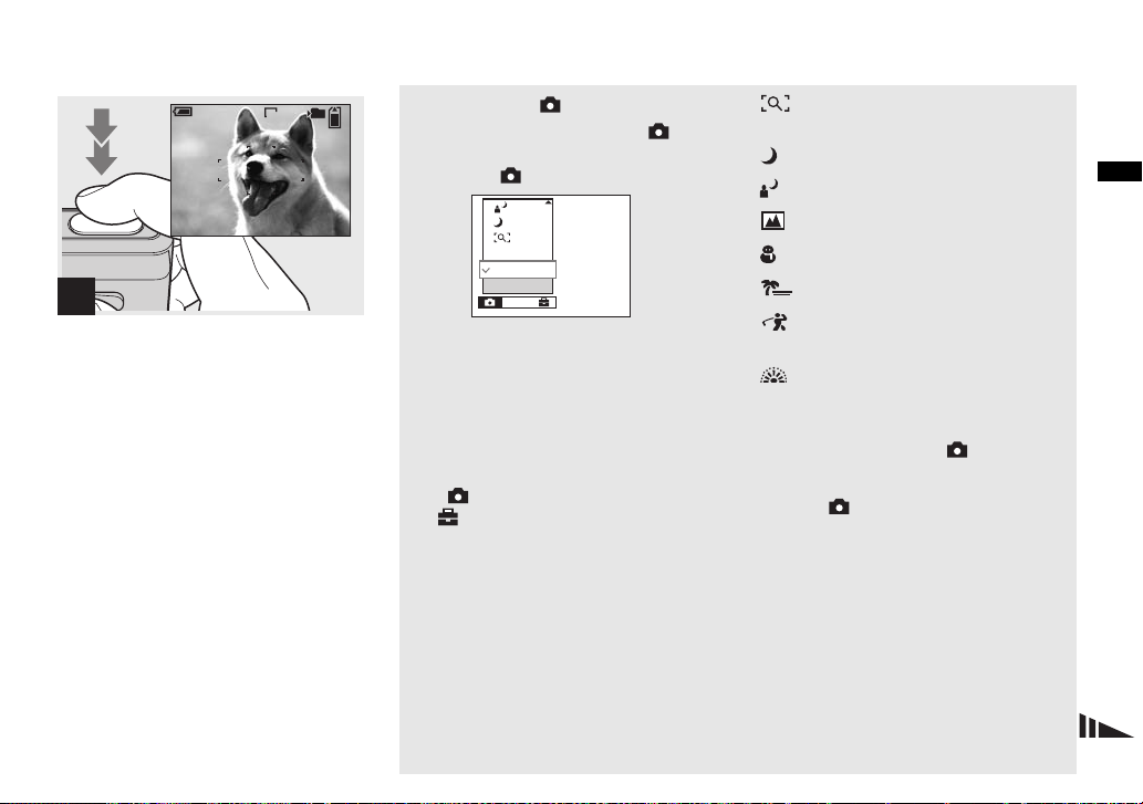
Basic still image shooting — Using auto adjustment mode
Mode switch
1
, Set the mode switch to , and
slide the lens cover to turn on
the power.
The name of the folder where the image will
be recorded appears on the LCD screen for
approximately five seconds.
• This camera can create new folders and select
folders to be stored in the “Memory Stick Duo”
(page 45).
2
, Hold the camera steadily with
both hands and position the
subject in the center of the
focus frame.
Do not touch the lens portion, flash portion,
or microphone (page 8) when you hold the
camera.
• The minimum focal distance to a subject is
approx. 50 cm (19 3/4 inches).
To shoot subjects at distances closer than this,
use close-ups (Macro) mode (page 27).
60min
S AF
AE/AF lock indicator
Flashes green t
3
Light up
101
FINE
VGA
96
F2.830
, Press and hold the shutter
button halfway down.
The beep sounds but the image is not yet
recorded. When the AE/AF lock indicator
changes from flashing to steadily lit, the
camera is ready for shooting.
(The LCD screen may be frozen for a split
second depending on the subject.)
• If you release the shutter button, shooting will
be canceled.
• When the camera does not beep, the AF
adjustment is not complete. You can continue to
shoot, but the AF is not set properly (except in
Continuous AF, page 48).
22
Page 29
60min
S AF
101
VGA
95
4
, Press the shutter button fully
down.
The shutter sounds. The image will be
recorded in the “Memory Stick Duo.” When
“Recording” disappears from the LCD
screen, you can shoot the next image.
• The frame indicated on the LCD screen shows
the focus adjustment range (AF range finder,
page 47).
• When operating the camera using a battery
pack, if you do not operate the camera for a
while during recording or playback, the camera
turns off automatically to prevent wearing
down the battery (page 16).
Mode switch
When you set the mode switch to , the
functions that can be used change as follows
according to (Camera) in the menu.
Program
Auto
Camera
Mode
Still image auto shooting [Auto]
The focus, exposure and white balance are
automatically adjusted as needed to allow
easy shooting. In addition, the image
quality is set to [Fine], the AF range finder
frame is set to [Multi AF], and the metering
mode is set to [Multi] (pages 47 and 52).
Only (Camera), [Mode] (REC Mode)
and (Setup) appear in the menu.
Still image program shooting
[Program]
The necessary adjustments are made
automatically like still image auto shooting,
but you can also change the focus and other
adjustments as desired. In addition, you can
also set the desired shooting functions using
menus (pages 43 and 102).
(Magnifying glass mode)
(page 32)
(Twilight mode) (page 32)
(Twilight portrait mode) (page 32)
(Landscape mode) (page 33)
(Snow mode) (page 33)
(Beach mode) (page 33)
(High-speed shutter mode)
(page 33)
(Fireworks mode) (page 33)
To switch the shooting method
1 Set the mode switch to .
2 Press MENU.
3 Select (Camera) with b on the
control button.
4 Select the desired shooting mode with
v/V on the control button.
Shooting still images
23
Page 30

Auto Focus
When you try to shoot a subject that is
difficult to focus on, the AE/AF lock
indicator changes to flashing slowly.
The Auto Focus function may have
difficulty working under the following
conditions. In such cases, release the shutter
button, then recompose the shot and focus
again.
• The subject is distant from the camera
and dark.
• The contrast between the subject and its
background is poor.
• The subject is seen through glass, such as
a window.
• A fast-moving subject.
• The subject reflects or has a lustrous
finish, such as a mirror or a luminous
body.
• A flashing subject.
• A backlit subject.
There are two Auto Focus functions: “AF
range finder frame” which sets the focus
position according to the subject position
and size, and “AF mode” which sets the
focus start/finish timing according to the
AF response and the battery consumption.
See page 47 for details.
Checking the last image you
shot — Quick Review
60min
VGA
8/8
Review
RETURN
101
10:30
2004 1 1101-0029
PM
, Press b (7) on the control
button.
To return to the normal shooting mode,
press lightly on the shutter button or press
b (7) again.
To delete the image displayed on the
LCD screen
1 Press (Delete).
2 Select [Delete] with v on the control
button, then press z.
The image is deleted.
24
Page 31
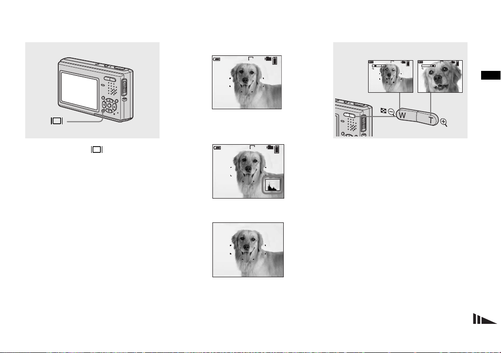
Indicators on the LCD screen during shooting
Using the zoom feature
Each time you press , the display
changes in the following order.
• When shooting/viewing movies, the status of
the LCD screen changes as follows: Indicators
on t Indicators off t LCD backlight off
• For a detailed description of the indicators, see
page 114.
• For a detailed description of the histogram, see
page 51.
• You can extend the battery remaining time by
turning off the LCD backlight.
• This setting is maintained even when the power
is turned off.
Indicators on
60min
S AF
Histogram on (Image information can also be
101
VGA
96
r
displayed during playback.)
60min
S AF
101
VGA
96
r
Indicators off
S AF
r
LCD backlight off
W (wide-angle) T (telephoto)
101 101
VGA
60min 60min
96
T
W
x1.1
S AF
VGA
T
W
S AF
96
x5.0
, Press the zoom button to
choose the desired image size
for shooting.
The minimum focal distance to the
subject
Approx. 50 cm (19 3/4 inches) from the lens
surface
• You cannot change the zoom scale while
shooting movie.
Shooting still images
25
Page 32

Zoom
Your camera is equipped with zoom
functions that enlarge the image using
optical zoom and two types of digital
processing. Digital zoom can be selected
from smart zoom or precision digital zoom.
When digital zoom is set, the zoom method
switches from optical zoom to digital zoom
when the zoom scale exceeds 3×.
To use only the optical zoom, set [Digital
Zoom] to [Off] on the Setup screen
(page 106). In this case, the digital zoom
area does not appear in the zoom scale
display bar on the LCD screen, and the
maximum zoom is 3×. The enlargement
method and the zoom scale differ according
to the image size and the zoom type, so
select the zoom to match the shooting
purpose.
When digital zoom is set and you press the
zoom button, the zoom scaling indicator
appears on the LCD screen as follows.
26
The W side of this line is optical zoom,
and the T side is digital zoom
Zoom scaling indicator
• The indicator differs according to the zoom
type.
– Optical zoom:
– Smart zoom:
– Precision digital zoom:
• The AF range finder frame does not appear
when using the digital zoom. The , or
indicators flashes, and AF operates with
priority on subjects located near the center.
Smart zoom
The image is enlarged with almost no
distortion. This lets you use smart zoom
with the same feeling as optical zoom. To
set smart zoom, set [Digital Zoom] to
[Smart] on the Setup screen (page 106).
When you purchase your camera, it is set to
smart zoom.
The maximum zoom scale depends on the
selected image size as follows.
Image size Maximum zoom scale
3M 3.8×
1M 6.1×
VGA 12×
When you purchase your camera,
the image size is set to [5M]. Smart
zoom cannot be used when the
image size is set to [5M] or [3:2], so
set a different image size.
• When using the smart zoom, the image on the
LCD screen may look rough. However, this has
no effect on the recorded image.
• You cannot use the smart zoom in the Multi
Burst mode.
Precision digital zoom
All image sizes are enlarged up to a
maximum 6×. This function cuts out and
enlarges a certain portion of the image, so
the image quality deteriorates. To set
precision digital zoom, set [Digital Zoom]
to [Precision] on the Setup screen
(page 106).
Page 33

Shooting close-ups — Macro
The close-ups (Macro) recording mode is
used when zooming up subjects such as
flowers or insects. Setting the zoom all the
way to the W side lets you shoot subjects at
distances as close as 8 cm. However, the
minimum focus distance varies according
to the zoom position. Therefore, shooting
with the zoom set all the way to the W side
is recommended.
When the zoom is set all the way to
the W side:
Approx. 8 cm (3 1/4 inches) from the lens
surface
When the zoom is set all the way to
the T side:
Approx. 25 cm (9 7/8 inches) from the lens
surface
• Using Spot AF is recommended (page 47).
• To shoot at even closer distances than close-ups
(Macro) recording, use (Magnifying glass
mode) (page 32).
60min
S AF
101
VGA
96
1
, Set the mode switch to , and
press B ( ) on the control
button.
The (macro) indicator appears on the
LCD screen.
• If the menu is currently displayed, press MENU
first so that the menu disappears.
• You can also carry out this operation when the
mode switch is set to .
• You cannot use this function when
(Camera) in the menu is set to
(Magnifying glass mode), (Twilight mode),
(Landscape mode) and (Fireworks
mode).
Shooting still images
27
Page 34
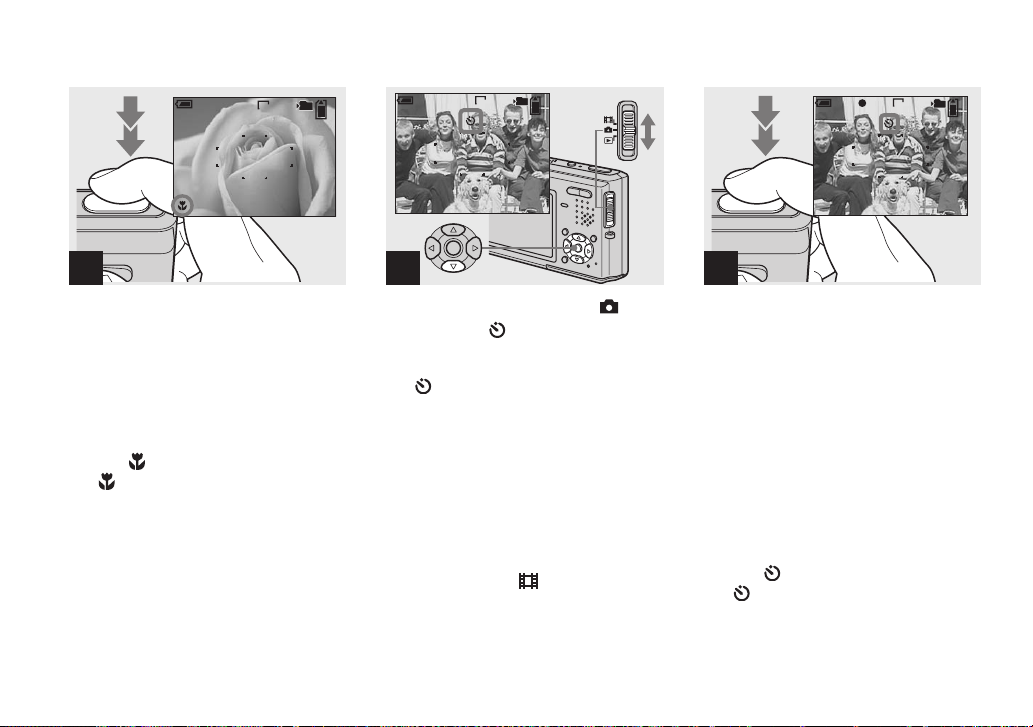
Using the self-timer
60min
S AF
2
, Center the subject in the frame.
Press and hold the shutter
button halfway down, then
press the shutter button fully
down.
To return to normal recording mode
Press B ( ) on the control button again.
The indicator disappears from the LCD
screen.
• When shooting in close-ups (Macro) mode, the
focus depth becomes extremely shallow, and
the entire subject may not be in focus.
• When shooting in close-ups (Macro) mode, the
AF speed drops in order to focus accurately on
close subjects.
28
101
VGA
95
60min
S AF
1
, Set the mode switch to , and
press V ( ) on the control
button.
The (self-timer) indicator appears on the
LCD screen.
• When recording with the self-timer, place the
camera in a stable location. If you place the
camera in an unstable location for recording,
the camera may fall and become damaged or
malfunction.
• If the menu is currently displayed, press MENU
first so that the menu disappears.
• You can also carry out this operation when the
mode switch is set to .
101
VGA
96
60min
S AF
FINE
101
VGA
96
F2.830
2
, Center the subject in the frame.
Press and hold the shutter
button halfway down, then
press the shutter button fully
down.
The self-timer lamp (page 8) flashes and a
beep sounds after you press the shutter
button until the shutter operates
(approximately 10 seconds later).
To cancel the self-timer in the middle
of the operation
Press V ( ) on the control button again.
The indicator disappears from the LCD
screen.
• If you press the shutter button while standing in
front of the camera, the focus and the exposure
may not be correctly set.
Page 35

Selecting a flash mode
60min
S AF
101
VGA
96
, Set the mode switch to , and
press v ( ) on the control
button repeatedly to select a
flash mode.
Each time you press v ( ), the indicator
changes as follows.
No indicator (Auto): The flash
automatically strobes when shooting
images in a dark place. The factory setting
is Auto.
(Forced flash): The flash strobes
regardless of the surrounding brightness.
(Slow synchro): The flash strobes
SL
regardless of the surrounding brightness.
The shutter speed is slow in a dark place, so
you can clearly shoot the background that is
out of flash light.
(No flash): The flash does not strobe
regardless of the surrounding brightness.
• If the menu is currently displayed, press MENU
first so that the menu disappears.
• When [ISO] is set to [Auto] in the menu, the
recommended shooting distance using the flash
is approx. 0.3 m to 1.5 m (11 7/8 inches to
59 1/8 inches) (W)/0.5 m to 1.5 m (19 3/4
inches to 59 1/8 inches) (T).
• You can change the brightness of the flash with
(Flash Level) in the menu (page 55). (You
cannot change the brightness of the flash while
(Camera) is set to [Auto] in the menu.)
• When using the (Slow synchro) or (No
flash) mode, the shutter speed becomes slower
in dark places. Be careful not to allow your
hand to shake while holding the camera.
• While charging the flash, the /CHG lamp
flashes. After the charging is complete, the
lamp goes out.
• This setting is maintained even when the power
is turned off.
SL
To prevent subjects’ eyes from
appearing red
Set [Red Eye Reduction] to [On] on the
Setup screen (page 106). The indicator
appears on the LCD screen, and the flash
pre-strobes before shooting to reduce the
red-eye phenomenon.
m
• Red-eye reduction may not produce the desired
effects depending on individual differences, the
distance to the subject, if the subject does not
see the pre-strobe, or other conditions.
Shooting still images
29
Page 36

Shooting images with the AF
N
illuminator
The AF illuminator is fill light to focus
more easily on a subject in dark
surroundings. The appears on the LCD
screen and the AF illuminator emits red
light when the shutter button is pressed
halfway until the focus is locked.
60min
S AF
When this function is not needed, set [AF
Illuminator] to [Off] on the Setup screen
(page 106).
• If AF illuminator light does not reach the
subject sufficiently or the subject has no
contrast, focus will not be achieved. (A distance
up to approximately 2.2 m (86 5/8 inches) is
recommended.)
• Focus is achieved as long as AF illuminator
light reaches the subject, even if the light is
slightly off the center of the subject.
• When the focus preset distance is set (page 49),
the AF illuminator does not function.
O
101
FINE
VGA
ON
96
F2.830
• The AF range finder frame does not appear.
The , or indicators flashes, and AF
operates with priority on subjects located near
the center.
• The AF illuminator operates only when
(Camera) is set to [Auto], [Program],
(Magnifying glass mode), (Twilight
portrait mode), (Snow mode) or
(Beach mode) in the menu.
• The AF illuminator emits very bright light.
Although there are no problems with safety,
directly looking into the AF illuminator emitter
at close range is not recommended, as you may
see residual spots for several minutes
afterwards, such as after looking into a
flashlight.
Inserting the date and time
on a still image
Program
Auto
Camera
Mode
MENU
1
, Set the mode switch to , then
press MENU.
The menu appears.
• When images are shot with the date and time
superimposed, the date and time cannot be
removed later.
• The date and time do not appear on the LCD
screen during shooting, instead, the
indicator appears on the LCD screen. The
actual date and time appear in red during
playback only.
• The date and time is not inserted in Multi Burst
mode.
• You can also carry out this operation with the
mode switch set to or .
30
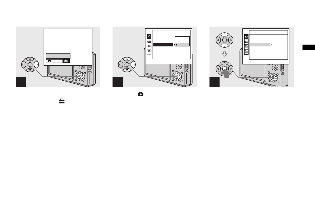
Page 37
Setup t
Mode
AF Mode:
Digital Zoom:
Date/Time:
1
Red Eye Reduction
2
AF Illuminator:
Auto Review:
Camera
:
Day&Time
Date
Off
AF Mode:
Digital Zoom:
Date/Time:
1
Red Eye Reduction
2
AF Illuminator:
Auto Review:
PAGE SELECT
Camera
Single
Smart
Day&Time
:
Off
Auto
On
Shooting still images
2
, Press B on the control button
to advance to , then press B
again.
The Setup screen appears.
3
, Select (Camera) with v on
the control button, then press
B.
Select [Date/Time] with v/V,
then press B.
4
, Select the date and time setting
with v/V on the control button,
then press z.
Day&Time: Superimposes the date, hour,
and minute onto the image.
Date: Superimposes the year, month and
day onto the image.
Off: Does not superimpose the date and
time onto the image.
After the setting has been completed, press
MENU first so that the menu disappears,
and shoot the image.
• If you select [Date], the date is superimposed
onto the image in the order selected in “Setting
the date and time” (page 17).
• This setting is maintained even when the power
is turned off.
31
Page 38
Shooting according to scene conditions — Scene Selection
You can select from eight different shooting
modes (magnifying glass, twilight, twilight
portrait, landscape, snow, beach, highspeed shutter and fireworks) in accordance
with the shooting conditions. The camera
automatically makes the optimum settings
to match the scene, making it easy to shoot
high quality images even under difficult
conditions.
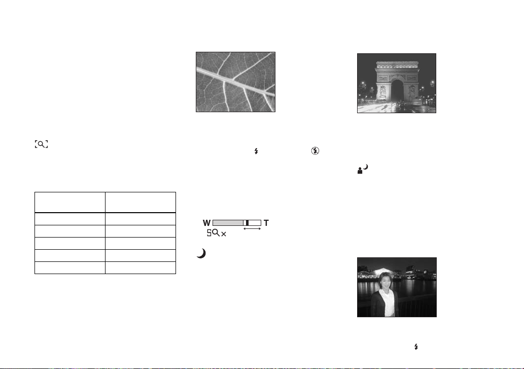
Magnifying glass mode
The subject appears on the LCD screen
magnified by up to 3.3×. This lets you see
details that would otherwise be difficult to
confirm with the naked eye.
Distance to the
subject
1 cm (13/32 inch) 3.3×
2 cm (13/16 inch) 2.1×
5 cm (2 inches) 1.0×
10 cm (4 inches) 0.5×
20 cm (7 7/8 inches) 0.3×
Magnification
scale
• The close-ups (Macro) function does not work.
• You cannot shoot in Exposure Bracket, Burst
and Multi Burst mode.
• The flash is set to (Forced flash) or (No
flash).
• The focal distance to a subject is approx. 1 cm
to 20 cm (13/32 inch to 7 7/8 inches).
• The optical zoom is locked to the W side and
cannot be used.
• When you press the zoom button, the image is
enlarged using the digital zoom.
1.1
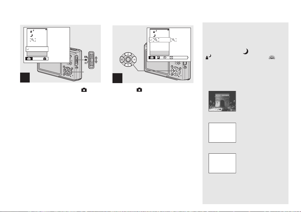
Twilight mode
Allows you to shoot night scenes at far
distance without losing the dark atmosphere
of the surroundings. The shutter speed
becomes slower, so be careful not to allow
your hand to shake while holding the
camera.
32
• The close-ups (Macro) function does not work.
• You cannot shoot in Exposure Bracket, Burst
and Multi Burst mode.
• You cannot use the flash.
Twilight portrait mode
Suitable for shooting portraits in dark
places. Allows you to shoot sharp images of
people in dark places without losing the
dark atmosphere of the surroundings. The
shutter speed becomes slower, so be careful
not to allow your hand to shake while
holding the camera.
• You cannot shoot in Exposure Bracket, Burst
and Multi Burst mode.
• The flash is set to (Slow Synchro).
SL
Page 39

Landscape mode
Focuses only on a distant subject to shoot
landscapes, etc.
Beach mode
When shooting seaside or lakeside scenes,
the blue of the water is clearly recorded.
Fireworks mode
Fireworks are recorded in all their splendor
by setting the focus distance to infinity. The
shutter speed becomes slower, so be careful
not to allow your hand to shake while
holding the camera.
Shooting still images
• The close-ups (Macro) function does not work.
• The flash is set to (Forced flash) or (No
flash).
Snow mode
When shooting snowy scenes or other
places where the whole screen appears
white, use this mode to prevent sunken
colors and record clear and sharp images.
• The flash is set to (Forced flash) or (No
flash).
• The flash is set to (Forced flash) or (No
flash).
High-speed shutter mode
Use this mode to shoot moving subjects
outdoors or in other bright places.
• The shutter speed becomes faster, so images
shot in dark places become darker.
• The flash is set to (Forced flash) or (No
flash).
• The close-ups (Macro) function does not work.
• You cannot use the flash.
• You can change the shutter speed by setting an
EV adjustment value (page 50).
• You cannot set the white balance.
• You cannot shoot in Exposure Bracket, Burst
and Multi Burst mode.
33
Page 40
Program
Auto
Camera
Mode
MENU
1
, Set the mode switch to , then
press MENU.
The menu appears.
Program
Auto
Camera
WB
ISO
2
, Select (Camera) with b on
the control button, then select
the desired mode with v/V.
To return to normal mode
Select [Auto] or [Program] with v/V on the
control button.
• The setting is maintained even when the power
is turned off.
NR slow shutter
The NR slow shutter mode removes noise
from recorded images, providing clear
images. When the shutter speed is 1/6
second or slower in (Twilight mode),
(Twilight portrait mode) and
(Fireworks mode), the camera
automatically enters the NR slow shutter
function and “NR” is indicated next to the
shutter speed indicator.
Press the shutter button
fully down.
F2.82
r
Then the screen turns
Capturing
r
Processing
• When the NR slow shutter function is activated,
be careful not to allow your hand to shake while
holding the camera.
black.
Finally, when
“Processing” disappears,
the image has been
recorded.
34
Page 41

Viewing still images
Viewing images on the LCD screen of your
camera
Single (single-image)
screen
60min
VGA
101
8/9
10:30
2004 1 1101-0008
BACK/NEXT VOLUME
PM
Index (nine-image)
screen
SINGLE DISPLAY
•
Index (sixteen-image)
screen
SINGLE DISPLAY
•
Viewing single images
60min
VGA
101
8/9
10:30
2004 1 1101-0008
BACK/NEXT VOLUME
PM
1
Viewing still images
You can view images shot with your camera
almost immediately on the LCD screen.
You can select the following three methods
for viewing images.
Single (single-image) screen
You can view one image at a time,
displayed over the entire screen.
Index (nine-image/sixteen-image)
screen
Nine or sixteen images are displayed
simultaneously in separate panels on the
LCD screen.
• For details on viewing movies, see page 71.
• For a detailed description of the indicators, see
page 116.
, Set the mode switch to , and
turn on the power.
The last image in the selected recording
folder (page 45) appears on the LCD
screen.
• The image may appear rough right after
playback starts due to the image processing.
35
Page 42

Viewing an index screen (nine-image or sixteen-image)
60min
VGA
101
3/9
10:30
2004 1 1101-0003
BACK/NEXT VOLUME
PM
SINGLE DISPLAY
•
SINGLE DISPLAY
•
2
, Select the desired still image
with b/B on the control button.
b : To display the preceding image
B : To display the next image
36
, Press (Index) once.
The display switches to the index (nineimage) screen.
To display the next (previous) index
screen
Press v/V/b/B on the control button to
move the yellow frame up/down/left/right.
, Press (Index) once more.
The display switches to the index
(sixteen-image) screen.
To display the next (previous) index
screen
Press v/V/b/B on the control button to
move the yellow frame up/down/left/right.
To return to the single-image screen
Press (Index) T side repeatedly, or
press z on the control button.
Page 43

Viewing images on a TV screen
A/V connecting cable
A/V OUT
1
(MONO) jack
2
Viewing still images
3
TV/Video switch
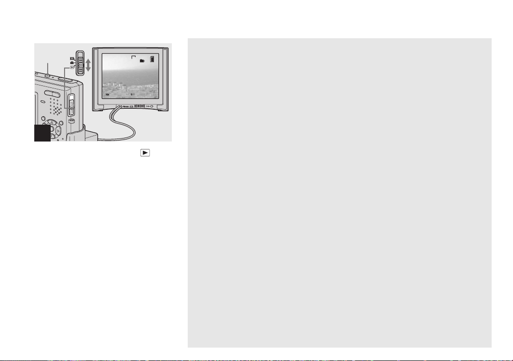
, Connect the A/V connecting
cable (supplied) to the A/V OUT
(MONO) jack of the USB cradle
(supplied) and the audio/video
input jacks of the TV.
If your TV has stereo type input jacks,
connect the audio plug (black) of the A/V
connecting cable to the left audio input jack.
• When the USB cable is connected to the USB
cradle, remove the USB cable from the USB
cradle.
• Turn off both the camera and the TV before
connecting the camera and the TV with the A/V
connecting cable.
, Connect the camera to the USB
cradle.
Connect the camera as illustrated.
• Make sure the camera is securely connected to
the USB cradle.
, Turn on the TV and set the TV/
Video switch to “Video”.
• The name and location of this switch may differ
depending on your TV. For details, see the
operating instructions supplied with the TV.
37
Page 44
POWER
VGA
2004 1 1101-0002
BACK/NEXT VOLUME
101
10:30
2/9
PM
4
, Set the mode switch to , and
turn on the camera.
Press b/B on the control button to select the
desired image.
• When using your camera abroad, it may be
necessary to switch the video output signal to
match that of your TV system (page 107).
Viewing images on a TV screen
If you want to view images on a TV screen,
you need a TV with a video input jack and
the A/V connecting cable (supplied).
The color system of the TV must match that
of your digital still camera. Check the
following lists:
NTSC system
Bahama Islands, Bolivia, Canada, Central
America, Chile, Colombia, Ecuador,
Jamaica, Japan, Korea, Mexico, Peru,
Surinam, Taiwan, the Philippines, the
U.S.A., Venezuela, etc.
PAL system
Australia, Austria, Belgium, China, Czech
Republic, Denmark, Finland, Germany,
Holland, Hong Kong, Italy, Kuwait,
Malaysia, New Zealand, Norway, Portugal,
Singapore, Slovak Republic, Spain,
Sweden, Switzerland, Thailand, United
Kingdom, etc.
PAL-M system
Brazil
PAL-N system
Argentina, Paraguay, Uruguay
SECAM system
Bulgaria, France, Guiana, Hungary, Iran,
Iraq, Monaco, Poland, Russia, Ukraine, etc.
38
Page 45
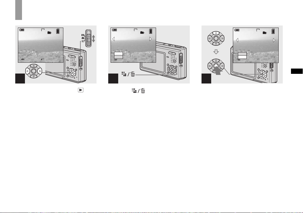
Deleting images
Deleting still images
60min
VGA
101
2/9
10:30
2004 1 1101-0002
BACK/NEXT VOLUME
PM
1
, Set the mode switch to , and
turn on the camera.
Press b/B on the control
button to select the image you
want to delete.
• Note that you cannot restore deleted images.
60min
VGA
101
2/9
Delete
Exit
BACK/NEXT
2
, Press (Delete).
The image has not yet been deleted at this
point.
• You cannot delete the protected image
(page 66).
60min
VGA
101
2/9
Delete
Exit
BACK/NEXT
3
, Select [Delete] with v on the
control button, then press z.
The message “Access” appears, and the
image has been deleted.
To continue and delete other images
Display the image to be deleted with b/B
on the control button. Then, select [Delete]
with v and press z.
To cancel deleting
Select [Exit] with V on the control button,
then press z.
Deleting still images
39
Page 46
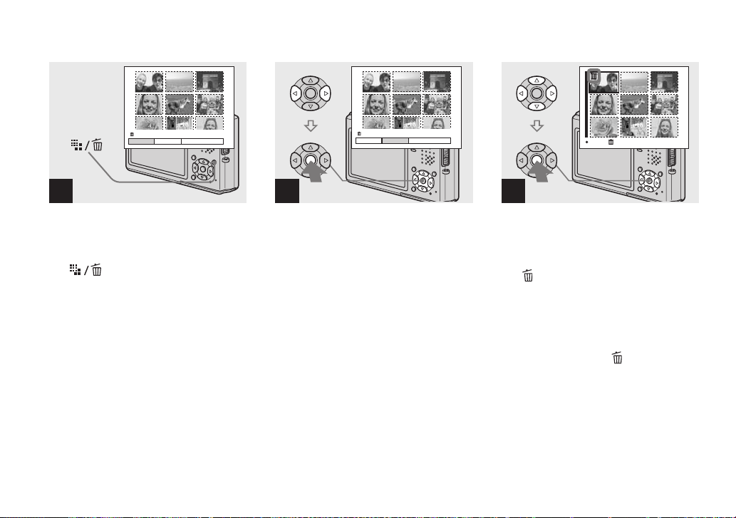
Deleting images in index (nine-image or sixteen-image) mode
Delete
SelectExit
1
, While an index (nine-image/
sixteen-image) screen
(page 36) is displayed, press
(Delete).
• Note that you cannot restore deleted images.
40
All In This Folder
Delete
SelectExit
All In This Folder
2
, Select [Select] with b/B on the
control button, then press z.
TO NEXTSELECT
3
, Select an image you want to
delete with v/V/b/B on the
control button, then press z.
The (Delete) indicator appears on the
selected image. At this point, the image has
not yet been deleted. Repeat this step for all
of the images you want to delete.
• To cancel a selection, select the image, then
press z again so that the indicator
disappears.
Page 47

Formatting a “Memory Stick Duo”
Delete Exit OK
4
, Press (Delete) and select
[OK] with B on the control
button, then press z.
The message “Access” appears, and the
images have been deleted.
To cancel deleting
Select [Exit] with b on the control button,
then press z.
To delete all the images in the
folder
Select [All In This Folder] with B on the
control button in step 2, then press z.
Select [OK], then press z. All of the
unprotected images in the folder are
deleted. To cancel deleting, select
[Cancel], then press z.
1
Terminal side
, Insert the “Memory Stick Duo”
you want to format into the
camera.
• The term “formatting” means preparing a
“Memory Stick Duo” to record images; this
process is also called “initialization.” The
“Memory Stick Duo” provided with this
camera, and those available commercially, are
already formatted, and can be used
immediately.
• When you format a “Memory Stick Duo,”
be aware that all data including
protected images in the “Memory Stick
Duo” will be permanently erased.
MENU
Setup t
Mode
2
, Turn on the camera, then press
MENU.
Press B on the control button
to advance to , then press B
again.
The Setup screen appears.
• This operation is available no matter what
position the mode switch is in.
Deleting still images
41
Page 48

Memory Stick Tool
Format:
Create REC. folder:
Change REC. folder:
1
2
OK
Cancel
60min
Format
All data will be erased
Ready?
OK
Cancel
3
, Select (Memory Stick Tool)
with v/V on the control button.
Select [Format] with B, then
press B.
Select [OK] with v, then press
z.
To cancel the formatting
Select [Cancel] with V on the control
button, then press z.
• Using the AC Adaptor is recommended to
prevent the power from turning off partway
through formatting.
42
4
, Select [OK] with v on the
control button, then press z.
The message “Formatting” appears. When
this message disappears, the format is
complete.
Page 49

How to setup and
operate your camera
The usage of the menus and Setup screen
items that are most frequently used for
“Advanced operations” is described below.
Control button
MENU
Mode switch
Before advanced operations
Changing the menu settings
a Press MENU.
The menu appears.
Program
Auto
Camera
WB
ISO
b Press b/B on the control
button to select the item you
want to set.
400
200
100
Auto
ISO
WB
ISO
c Press v/V on the control
button to select the desired
setting.
The selected setting is enlarged and the
setting is entered.
When a v or V mark is displayed
next to a setting item
This means that there are also other setting
items. To display these other items, scroll
the screen with v/V.
To turn off the menu display
Press MENU again.
• You cannot select items displayed in gray.
• For a detailed description of the menu items,
see page 102.
Before advanced operations
43
Page 50
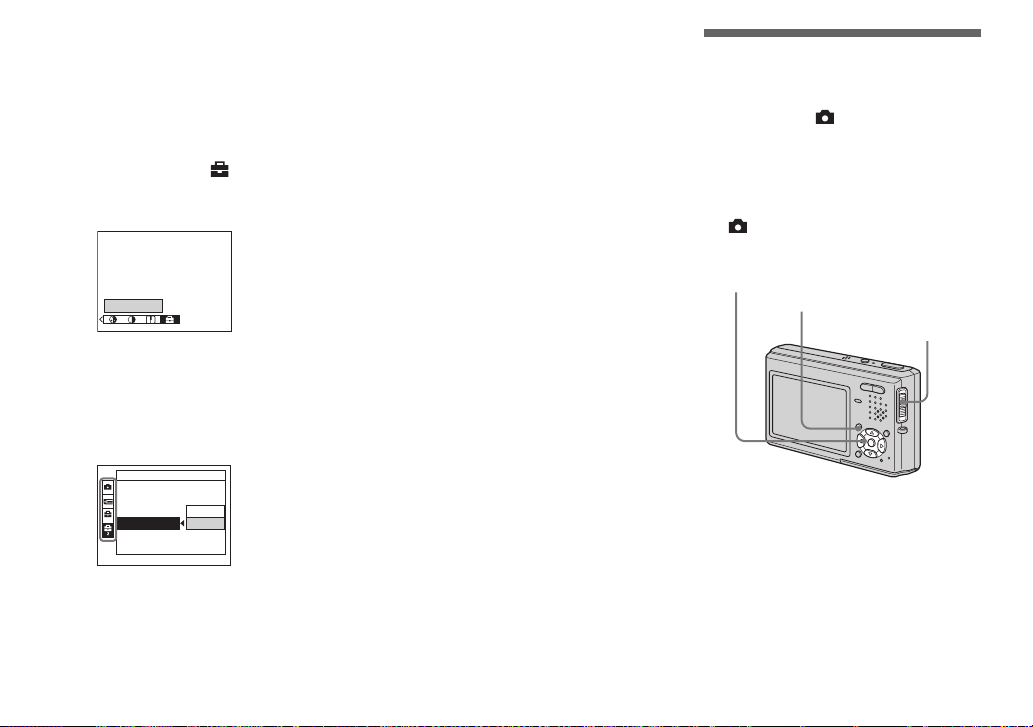
Changing the items on the
Setup screen
a Press MENU.
The menu appears.
b Press B on the control button
to advance to , then press B
again.
The Setup screen appears.
To cancel the Setup screen
Press MENU again.
To return to the menu from the
Setup screen
Press b on the control button to return to the
position enclosed by the frame in step 3,
then press b again.
• For a detailed description of the Setup items,
see page 106.
Deciding the still
image quality
Mode switch:
You can select the still image quality from
[Fine] or [Standard].
Before operation
Set (Camera) in the menu to other than
[Auto] (pages 43 and 102).
Setup t
c Press v/V/b/B on the control
button to select the item you
want to set.
The frame of the selected item turns
yellow.
Setup 2
File Number:
USB Connect:
Video Out:
1
Clock Set:
OK
Cancel
d Press z on the control button
to enter the setting.
44
Control button
MENU
Mode switch
Page 51
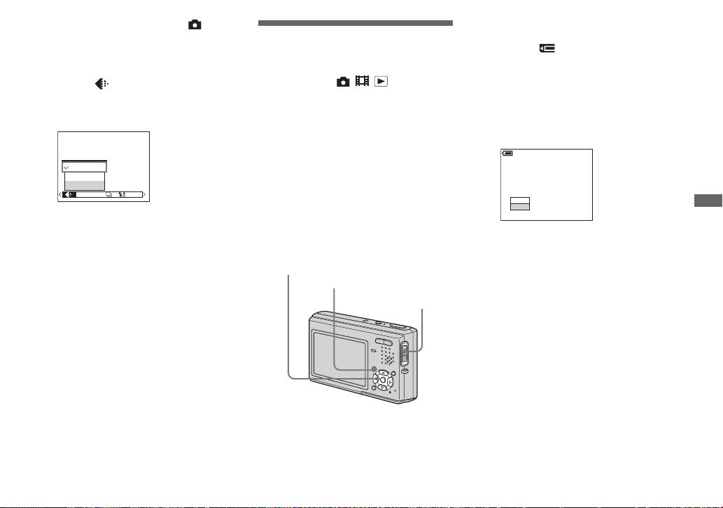
a Set the mode switch to .
b Press MENU.
The menu appears.
c Select (P.Quality) with b/B,
then select the desired image
quality with v/V.
Fine
FINE
Standard
P.Quality
M
Mode BRK
PFX
Creating or selecting
a folder
Mode switch: / /
Your camera can create multiple folders
within a “Memory Stick Duo.” You can
select the folder used to store images.
When not creating a new folder,
“101MSDCF” folder is selected as the
recording folder.
You can create folders up to “999MSDCF.”
Before operation
Set the menu to the Setup screen (pages 44
and 106).
Control button
MENU
Mode switch
• Up to 4000 images can be stored in one folder.
When the folder capacity is exceeded, a new
folder is automatically created.
Creating a new folder
a Select (Memory Stick Tool)
with v/V.
b Select [Create REC. Folder]
with B/v/V, and [OK] with B/v,
then press z.
The creating folder screen appears.
60
min
Create REC. Folder
Creating REC. folder 102MSDCF
Ready?
OK
Cancel
c Select [OK] with v, then press
z.
A new folder is created with a number
one higher than the largest number in
the “Memory Stick Duo”, and the
folder becomes the recording folder.
To cancel folder creation
Select [Cancel] in step 2 or 3.
• Once you create a new folder, you cannot delete
the new folder with the camera.
• Images are recorded in the newly created folder
until a different folder is created or selected.
Before advanced operations
45
Page 52

Changing the recording
folder
a Select (Memory Stick Tool)
with v/V.
b Select [Change REC. Folder]
with B/V, and [OK] with B/v,
then press z.
The recording folder selection screen
appears.
Select REC. Folder
102 2/2
102MSDCF
Folder Name:
No. Of Files:
0
Created:
2004
111::05:34
OK
Cancel
BACK/NEXT
AM
c Select the desired folder with
b/B, and [OK] with v, then
press z.
To cancel changing the
recording folder
Select [Cancel] in step 2 or 3.
• You cannot select the “100MSDCF” folder as a
recording folder.
• The image is stored in the newly selected
folder. You cannot move images to a different
folder with this camera.
46
Page 53
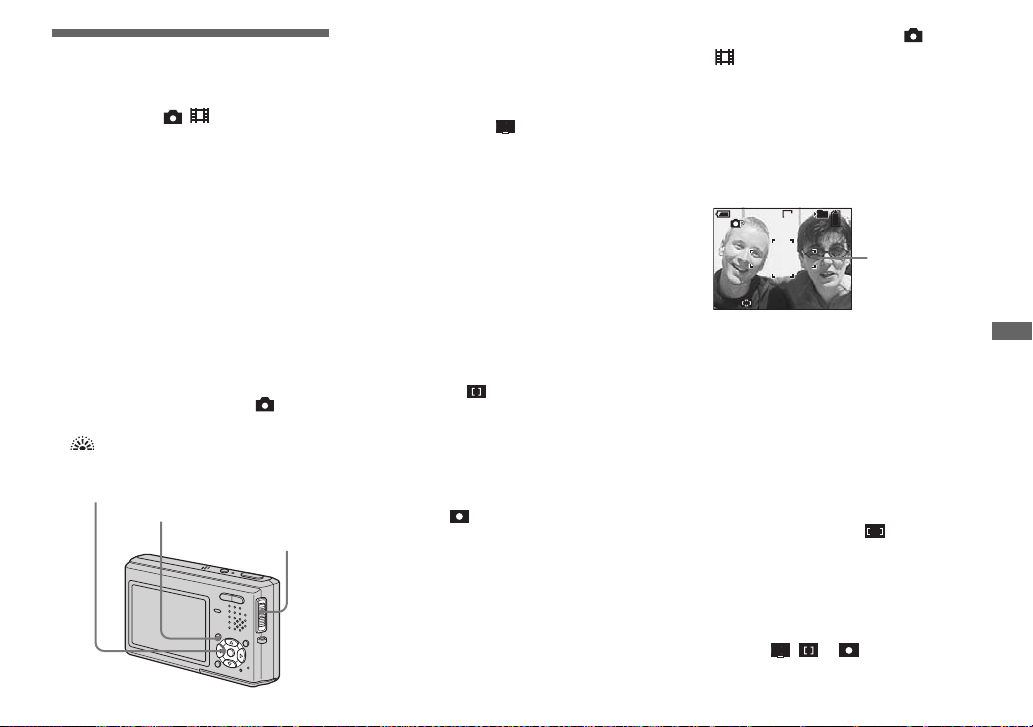
Advanced still image shooting
Choosing an auto
focus method
Mode switch: /
You can set the AF range finder frame and
the AF mode.
AF range finder frame
The AF range finder frame selects the focus
position according to the subject position
and size.
AF Mode
The AF mode sets the focus start/finish
timing according to the AF response and the
battery consumption.
Before operation
When shooting still images, set
(Camera) in the menu to other than [Auto]
or (Fireworks mode) (pages 43 and
102).
Control button
MENU
Mode switch
Choosing a focus range
finder frame
— AF range finder
Multipoint AF ( )
The camera calculates the distance in five
places to the left, right, top, bottom and in
the center of the image, letting you shoot
using the auto focus function without
worrying about the image composition.
This is useful when it is difficult to focus on
the subject because it is not in the center of
the frame. You can check the position
where the focus was adjusted using the
green frame.
The Multipoint AF is the factory setting.
Center AF ( )
This is useful for focusing on a subject near
the center of the frame. Use together with
the AF lock function lets you shoot in the
desired image composition.
Spot AF ( )
This is useful when focusing on an
extremely small subject or a narrow area.
Use together with the AF lock function lets
you shoot in the desired image composition.
Take care to hold the camera steady so that
the subject does not deviate from the range
finder frame.
a Set the mode switch to or
.
b Press MENU.
The menu appears.
c Select 9 (Focus) with b/B,
then select the desired AF
range with v/V.
60min
S AF
101
FINE
VGA
98
AF range
finder frame
The focus is adjusted automatically.
When you press and hold the shutter
button halfway down and the focus is
adjusted, the color of the AF range
finder frame changes from white to
green.
• When you are shooting movies and you choose
Multipoint AF, the distance to the center of the
screen is estimated as an average, so the AF
works even with a certain amount of vibration.
The AF range finder frame is . Center AF
and Spot AF automatically focus only on
selected frame, so these are convenient when
you want to focus only on what you aim at.
• When you use the digital zoom or AF
illuminator, priority AF movement is given to
subjects in or near the center of the frame. In
this case the , or indicator flashes
and the AF range finder frame is not displayed.
Advanced still image shooting
47
Page 54

Choosing a focus operation
— AF Mode
Single AF ( )
This mode is useful for shooting stationary
subjects. The focus is not adjusted before
the shutter button is pressed and held
halfway down. When the shutter button is
pressed and held halfway down and AF lock
is complete, the focus is locked.
The factory setting is Single AF.
Monitoring AF ( )
This shortens the time needed for focusing.
The camera automatically adjusts the focus
before the shutter button is pressed and held
halfway down, letting you compose images
with the focus already adjusted. When the
shutter button is pressed and held halfway
down and AF lock is complete, the focus is
locked.
• Battery consumption may be faster than in
Single AF mode.
S AF
M A F
Continuous AF ( )
C AF
The camera adjusts the focus before the
shutter button is pressed and held halfway
down, and then continues to adjust the focus
even after AF lock is completed. This
allows shooting of moving subjects with
continued focus.
• The focus is not adjusted after the lock is
completed in the following cases, and the
indicator flashes. The camera operates in
Monitoring AF mode.
– When shooting in the dark place
– When shooting with a slow shutter speed
• The AF range finder frame is set to Center AF.
• Focus adjustment may not be able to keep up
when shooting fast moving subjects.
• There is no lock sound when the focus is
adjusted.
• When recording with the self timer, the focus is
locked when you press the shutter button all the
way down.
• Battery consumption may be faster than in any
other AF mode.
C AF
Before operation
Set the menu to the Setup screen (pages 44
and 106).
a Select (Camera) with v.
b Select [AF Mode] with B/v,
and select the desired mode
with B/v/V.
Camera
x
:
Single
Monitor
Cont
AF Mode:
Digital Zoom:
Date/Time:
1
Red Eye Reduction
2
AF Illuminator:
Auto Review:
When you select [Single] or [Monitor],
also select the AF range finder frame
(page 47).
48
Page 55

Shooting techniques
When shooting with the subject at the edge of
the frame, or when using Center AF or Spot
AF, the camera may focus on the center instead
of on the subject at the edge of the frame. In a
case like this, use AF lock to focus on the
subject, and then recompose the picture and
shoot (except in Continuous AF mode).
Compose the shot so that the subject is
centered in the AF range finder, and press the
shutter button halfway down.
When the AE/AF lock indicator stops flashing
and remains on, return to the fully composed
shot, and press the shutter button fully down.
AE/AF lock indicator
60min FINE
101
VGA
98
AF range
finder frame
• When you are using AF lock, you can
capture an image with the correct focus even
if the subject is at the edge of the frame.
• You can carry out the AF lock adjustment
process before you press the shutter button
fully down.
Setting the distance
to the subject
— Focus preset
Mode switch: /
When shooting an image using a previously
set distance to the subject, or when shooting
a subject through a net or through window
glass, it is difficult to get the proper focus in
auto focus mode. In these cases, use of the
Focus preset is convenient.
Before operation
When shooting still images, set
(Camera) in the menu to other than [Auto]
or (Magnifying glass mode) (pages 43
and 102).
Advanced still image shooting
S AF
m
60min FINE
VGA
S AF
F2.8 30
Control button
101
97
MENU
Mode switch
49
Page 56

a Set the mode switch to or
.
b Press MENU.
The menu appears.
c Select 9 (Focus) with b/B,
then select the distance to the
subject with v/V.
You can select from the following
distance settings.
0.5m, 1.0m, 3.0m, 7.0m,
∞ (unlimited
distance)
1.0m
0.5m
0.5m
Spot AF
Center AF
Multi AF
Focus
WB
ISO
To return to auto focus mode
Select [Multi AF], [Center AF] or [Spot
AF] in step 3.
• Focal point information may not show the exact
distance.
• When (Camera) in the menu is set to
(Landscape mode) or (Fireworks mode),
the focus preset is restricted to ∞ (unlimited
distance).
Adjusting the
exposure
— EV adjustment
Mode switch: /
You can manually change the exposure set
by the camera. This function lets you obtain
the proper exposure when the contrast
(difference between bright and dark)
between the subject and the background is
extremely large. You can select values
ranging from +2.0EV to –2.0EV in steps of
1/3EV.
Before operation
When shooting still images, set
(Camera) in the menu to other than [Auto]
(pages 43 and 102).
Control button
MENU
Mode switch
a Set the mode switch to or
.
b Press MENU.
The menu appears.
c Select (EV) with b/B.
The value of the exposure adjustment
is displayed.
0EV
0EV
EV
WB
ISO
d Select the desired exposure
value.
Select the value with v/V. Adjust the
exposure value while checking the
brightness of the background.
To reactivate auto exposure
Select [0EV] in step 4.
• If a subject is being shot in extremely bright or
dark conditions, or the flash is used, the
exposure adjustment may not be effective.
50
Page 57

Displaying a histogram
A histogram is a graph showing the
brightness of an image. The horizontal axis
shows the brightness, and the vertical axis
shows the number of pixels. The graph
display indicates a dark image when
skewed to the left side, and a bright image
when skewed to the right side. The
histogram is useful to check the exposure
during recording and playback when the
screen is difficult to see.
101
FINE
5M
4
0
EV
Number of pixels
80
Brightness
BrightDark
a Set the mode switch to .
b Press to display the
histogram.
c Press MENU.
The menu appears.
d Adjust the exposure based on
the histogram.
• The histogram also appears when the
(Camera) in the menu is set to [Auto], but you
cannot adjust the exposure.
• The histogram also appears when you press
while playing back a single image
(page 35) or during Quick Review (page 24).
• The histogram does not appear in the following
cases:
– During Quick Review of an image recorded
in Exposure Bracket mode
– When using playback zoom
– When viewing and shooting movies
• appears in the following cases:
– When recording in the digital zoom range
– When the image size is [3:2]
– When rotating a still image
– When viewing Multi Burst images
• The histogram before recording represents the
histogram of the image displayed on the LCD
screen at that time. A difference occurs in the
histogram before and after you press the shutter
button. When this happens, check the hi stogram
while playing back a single-image or during
Quick Review.
In particular a large difference may appear in
the following cases:
– When the flash strobes
– When [PFX] (P.Effect) is set to [Solarize]
– When the shutter speed is slow or high
• The histogram may not appear for images
recorded using other cameras.
Shooting techniques
Normally, the camera automatically sets the
exposure. If the image is too dark or too
bright as shown below, we recommend that
you adjust the exposure value manually with
viewing the histogram. When shooting a
back-lit subject or a subject against a white
(e.g. snowy) background, adjust the
exposure toward the + side. When shooting a
black subject that fills the screen, adjust the
exposure toward the – side.
Advanced still image shooting
Underexposed t Adjust toward +
Appropriate exposure
Overexposed t Adjust toward –
51
Page 58
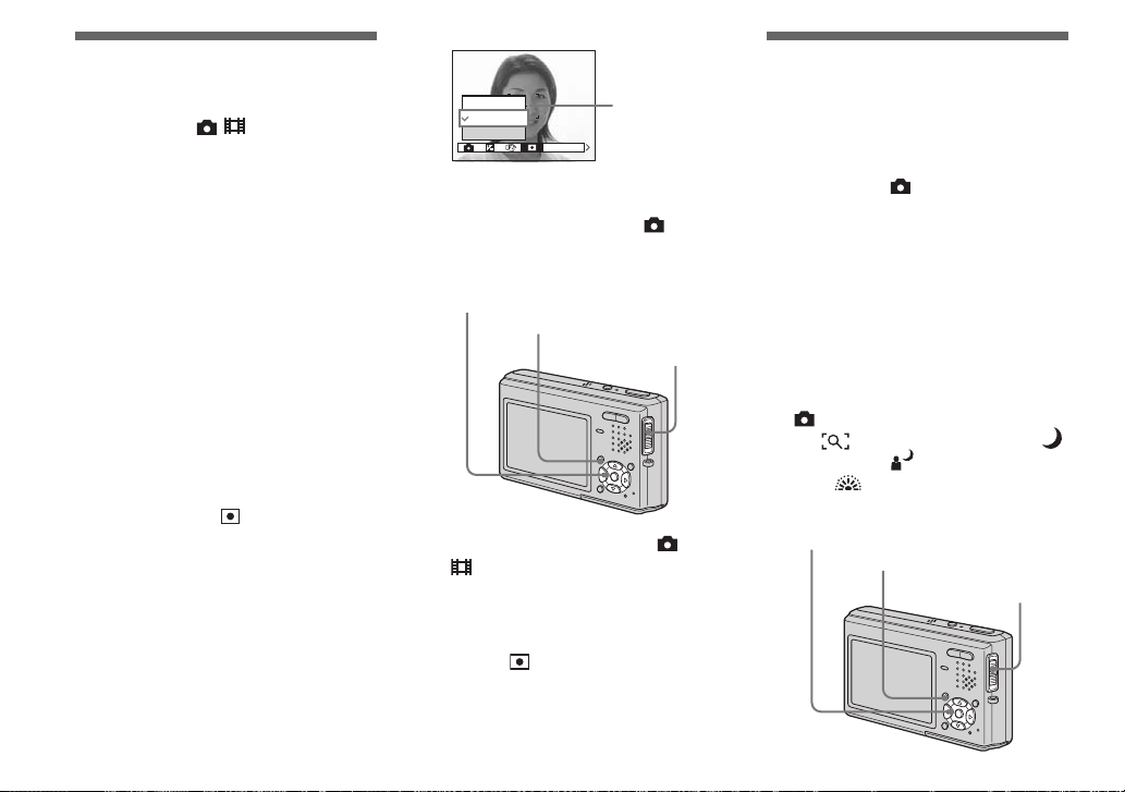
Selecting the
metering mode
Mode switch: /
The camera measures the brightness to
determine the exposure. This function lets
you select the following two metering
modes to determine which portion of the
subject to use for measuring the brightness.
Multi-pattern metering (no
indicator)
The image is divided into multiple regions
and metering is performed for each region.
The camera judges the subject position and
background brightness, and determines a
well-balanced exposure.
The factory setting is multi-pattern
metering.
Spot metering ( )
Metering is performed for only a portion of
the subject. This lets you adjust the
exposure to the subject even when the
subject is backlit or there is strong contrast
between the subject and the background.
Position the spot metering cross hair on one
point of the subject you want to shoot.
To focus on the metering position, setting
9 (Focus) to [Center AF] is recommended
(page 47).
52
ISO
Spot metering
cross hair
Spot
Multi
Metering Mode
WB
Before operation
When shooting still images, set
(Camera) in the menu to other than [Auto]
(pages 43 and 102).
Control button
MENU
Mode switch
a Set the mode switch to or
.
b Press MENU.
The menu appears.
c Select (Metering Mode) with
b/B, then select the desired
metering mode with v/V.
Shooting three
images with the
exposure shifted
— Exposure Bracket
Mode switch:
The Exposure Bracket function records a
series of three images with the exposure
values automatically shifted. This lets you
select the image with the appropriate
exposure after recording when you are
unable to shoot good pictures depending on
the brightness of the subject.
Before operation
Set (Camera) in the menu to other than
[Auto], (Magnifying glass mode),
(Twilight mode), (Twilight portrait
mode) or (Fireworks mode) (pages 43
and 102).
Control button
MENU
Mode switch
Page 59
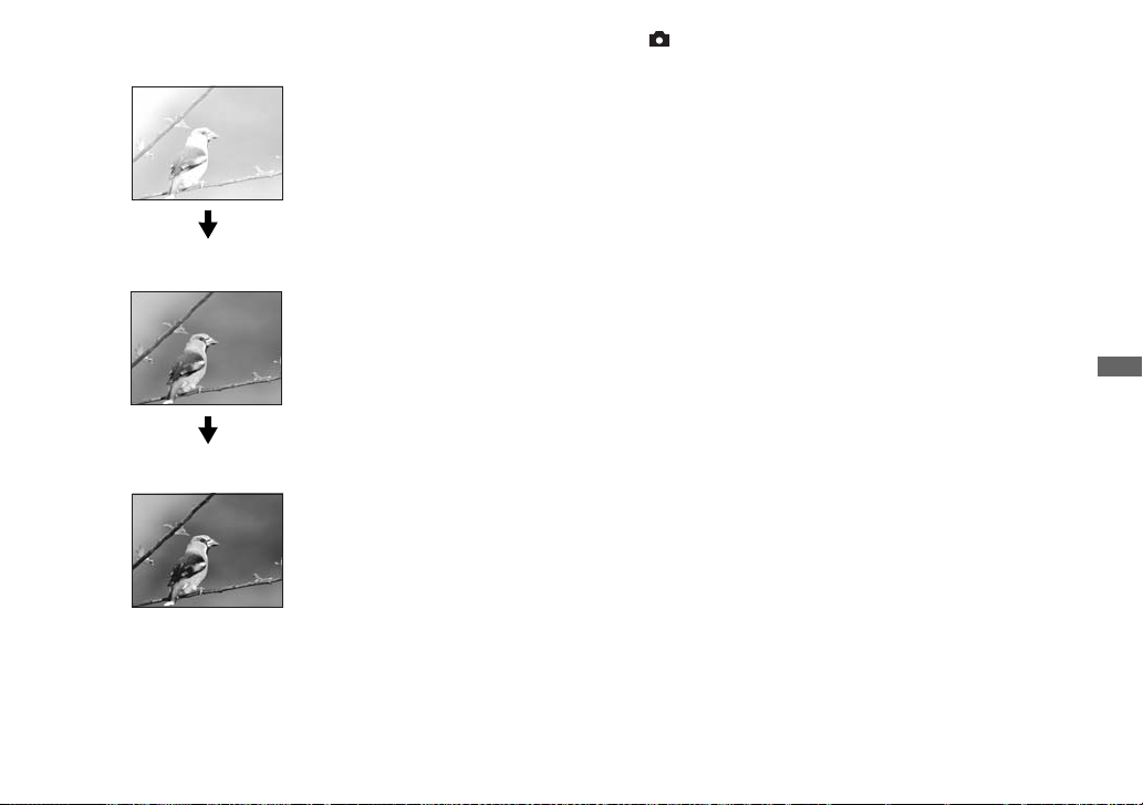
1st image (shifted in the
+ direction)
2nd image (appropriate
exposure for the camera)
3rd image (shifted in the
– direction)
a Set the mode switch to .
b Press MENU.
The menu appears.
c Select [Mode] (REC Mode) with
b/B, then select [Exp Brktg]
with v/V.
d Select [BRK] (Bracket Step)
with b/B, then select the
desired exposure adjustment
value with v/V.
±1.0EV: Shifts the exposure value by
plus or minus 1.0EV.
±0.7EV: Shifts the exposure value by
plus or minus 0.7EV.
±0.3EV: Shifts the exposure value by
plus or minus 0.3EV.
e Shoot the image.
To return to normal mode
Select [Normal] in step 3.
• You cannot use the flash in this mode.
• During shooting in this mode, the images are
not displayed on the LCD screen. Compose the
image before pressing the shutter button.
• The focus and white balance are adjusted for
the first image, and these settings are also used
for the other images.
• When the exposure is manually adjusted
(page 50), the exposure is shifted based on the
adjusted brightness.
• The recording interval is approximately
0.36 second.
• If the subject is too bright or too dark, you may
be unable to shoot properly with the selected
bracket adjustment value.
Advanced still image shooting
53
Page 60
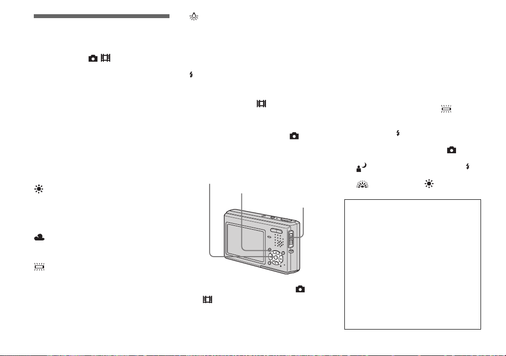
Adjusting color tones
— White Balance
Mode switch: /
When the white balance is set to Auto, the
white balance is automatically set and the
overall color balance is adjusted according
to the shooting conditions. However, when
you shoot under fixed conditions or special
lighting conditions, you can manually
adjust the white balance.
Auto (no indicator)
Adjusts the white balance automatically.
The factory setting is [Auto].
(Daylight)
Shooting outdoors, shooting night scenes,
neon signs, fireworks or sunrise, or
shooting just before and after sundown
(Cloudy)
Shooting under a cloudy sky
(Fluorescent)
Shooting under fluorescent lighting
54
(Incandescent)
• Places where the lighting conditions
change quickly
• Under bright lighting such as
photography studios
(Flash)
WB
Adjusts the white balance only to the flash
conditions (It does not appear when the
mode switch is set to .)
Before operation
When shooting still images, set
(Camera) in the menu to other than [Auto]
(pages 43 and 102).
Control button
MENU
Mode switch
a Set the mode switch to or
.
b Press MENU.
The menu appears.
c Select [WB] (White Bal) with b/
B, then select the desired
setting with v/V.
To reactivate auto adjustment
Select [Auto] in step 3.
• Under fluorescent lights that flicker, the white
balance adjustment function may not work
correctly even though you select .
• When the flash strobes, the manual setting is
canceled, and the image is recorded in [Auto]
mode (except in mode).
• The available White Balance settings are
limited as follows according to the
(Camera) setting in the menu:
– (Twilight Portrait mode): [Auto] or
(Flash) only
– (Fireworks mode): (Daylight) only
Shooting techniques
The subject coloring is affected by the
lighting conditions. For example, the entire
image appears blue under sunlight in the
summer, and white items gain a reddish tint
under incandescent light bulbs, etc. The
human eye can resolve these problems, but
digital still cameras cannot recognize the
correct colors without adjustments.
Normally, the camera makes these
adjustments automatically, but if recorded
image colors appear unnatural, we
recommend that you adjust the white
balance.
WB
WB
Page 61

Adjusting the flash
level
— Flash Level
Mode switch:
You can adjust the amount of flash light.
Before operation
Set (Camera) in the menu to other than
[Auto], (Twilight mode) or
(Fireworks mode) (pages 43 and 102).
Control button
MENU
Mode switch
a Set the mode switch to .
b Press MENU.
The menu appears.
c Select (Flash Level) with b/
B, then select the desired
setting with v/V.
High: Makes the flash level higher
than normal.
Normal: Normal setting.
Low: Makes the flash level lower than
normal.
Shooting images
continuously
— Burst
Mode switch:
This mode is used for continuous shooting.
Each time you press and hold the shutter
button in this mode, the camera records
maximum four images in succession.
Speed priority burst ( )
The images are shot with a short interval
(approx. 0.33 second). During shooting in
this mode, the images are not displayed on
the LCD screen. Compose the image before
pressing the shutter button.
Framing priority burst ( )
Shooting is performed while displaying the
images on the LCD screen. The shooting
interval (approx. 0.36 second) becomes
longer than speed priority burst.
• When a “Memory Stick Duo” becomes full,
shooting stops even if you continue to hold
down the shutter button.
S
F
Advanced still image shooting
55
Page 62

Before operation
Set (Camera) in the menu to other than
(Magnifying glass mode),
(Twilight mode), (Twilight portrait
mode) or (Fireworks mode) (pages 43
and 102).
Control button
MENU
Mode switch
a Set the mode switch to .
b Press MENU.
The menu appears.
c Select [Mode] (REC Mode) with
b/B, then select from [Speed
Burst] or [Framing Burst] with
v/V.
d Shoot the image.
You can also shoot only two or three
images by releasing the shutter button
partway.
When the message “Recording”
disappears, you can shoot the next
image.
To return to normal mode
Select [Normal] in step 3.
• You cannot use the flash in this mode.
• When recording with the self timer, a series of
four images are recorded each time you press
the shutter button.
Shooting in Multi
Burst mode
— Multi Burst
Mode switch:
This mode records 16 frames in succession
each time you press the shutter button. This
is convenient for checking your form in
sports, for example.
Before operation
Set (Camera) in the menu to other than
(Magnifying glass mode),
(Twilight mode), (Twilight portrait
mode) or (Fireworks mode) (pages 43
and 102).
Control button
MENU
Mode switch
56
a Set the mode switch to .
b Press MENU.
The menu appears.
Page 63

c Select [Mode] (REC Mode) with
b/B, then select [Multi Burst]
with v/V.
d Select (Interval) with b/B,
M
then select the desired frame
interval with v/V.
You can choose the frame interval
from [1/7.5], [1/15] or [1/30].
1/7.5
1/15
1/30
1/30
Interval
M
Mode BRK
PFX
e Shoot the image.
A continuous burst of 16 frames are
recorded within a single still image
(image size 1M).
• You cannot use the following functions in Multi
Burst mode:
–Smart zoom
–Flash
– Inserting the date and time
• When (Camera) in the menu is set to
[Auto], the frame interval is fixed to [1/30].
• See page 64 to play back Multi Burst images
using this camera.
• For the number of images that can be recorded
in Multi Burst mode, see page 100.
Shooting still images
for e-mail
— E-Mail
Mode switch:
In E-mail mode, a small-size image
(320×240) that is suitable for e-mail
transmission is also recorded at the same
time as recording a normal still image. (See
page 20 for the normal still image sizes.)
Control button
MENU
Mode switch
a Set the mode switch to .
b Press MENU.
The menu appears.
c Select [Mode] (REC Mode) with
b/B, then select [E-Mail] with
v/V.
d Shoot the image.
When the message “Recording”
disappears, you can shoot the next
image.
To return to normal mode
Select [Normal] in step 3.
• For instructions on how to attach images to an
e-mail message, consult the User’s Manual for
your e-mail software.
• For the number of images you can record in
E-mail mode, see page 100.
Advanced still image shooting
57
Page 64

Shooting still images
with audio files
— Voice
Mode switch:
In Voice mode, an audio track is also
recorded at the same time as recording a
normal still image.
Control button
MENU
Microphone
Mode switch
d Shoot the image.
If you press and release the
shutter button, sound is recorded
for five seconds.
If you hold down the shutter
button, sound is recorded until you
release the shutter button for up to
40 seconds.
To return to normal mode
Select [Normal] in step 3.
• To view images recorded in Voice mode, carry
out the same procedure described in “Viewing
movies on the LCD screen” (page 71).
• Do not touch the microphone during shooting
images in this mode.
• For the number of images you can record in
Voice mode, see page 100.
Adding special effects
— Picture Effect
Mode switch: /
You can digitally process images to obtain
special effects.
Solarize
Sepia
The light contrast is
clearer and the picture
looks like an
illustration.
The picture is sepiatoned like an old
photograph.
a Set the mode switch to .
b Press MENU.
The menu appears.
c Select [Mode] (REC Mode) with
b/B, then select [Voice] with v.
58
Neg.Art
The color and
brightness of the
picture are reversed
as in a negative.
Page 65

Before operation
When shooting still images, set
(Camera) in the menu to other than [Auto]
(pages 43 and 102).
Control button
MENU
Mode switch
a Set the mode switch to or
.
b Press MENU.
The menu appears.
c Select [PFX] (P.Effect) with b/
B, then select the desired
mode with v/V.
d Shoot the image.
To cancel Picture Effects
Select [Off] in step 3.
Advanced still image shooting
59
Page 66

Advanced still image viewing
Selecting the folder
and playing back
images
— Folder
Mode switch:
Select the folder that images you want to
playback are stored.
Control button
MENU
Mode switch
a Set the mode switch to .
b Press MENU.
The menu appears.
c Select (Folder) with b, then
press z.
d Select the desired folder with
b/B.
Select Folder
102 2/2
102MSDCF
Folder Name:
No. Of Files:
9
Created:
2004
111::05:34
OK
Cancel
BACK/NEXT
AM
e Select [OK] with v, then press
z.
To cancel the selection
Select [Cancel] in step 5.
When multiple folders are
created in the “Memory Stick
Duo”
When the first or last image in the folder is
displayed, the following indicators appear
on the LCD screen.
: Moves to the previous folder.
: Moves to the next folder.
: Moves to both the previous and next
folders.
Single screen
60
min
VGA
101
9/9
10:30
2004 1 1101-0009
BACK/NEXT VOLUME
PM
Index (nine-image) screen
SINGLE DISPLAY
Index (sixteen-image) screen
SINGLE DISPLAY
•
• When no images are stored in the folder, “No
file in this folder” appears.
• You can play back images from a last-shot one
without selecting the folder.
60
Page 67
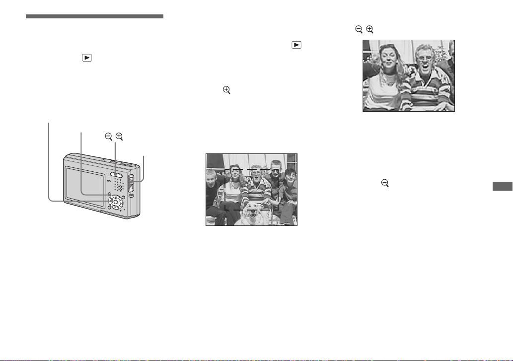
Enlarging a portion of
a still image
Mode switch:
You can enlarge a part of an image up to
five times the original size. You can also
record the magnified image as a new file.
Control button
MENU
/
Mode switch
Enlarging an image
— Playback zoom
a Set the mode switch to .
b Display the image to be
enlarged with b/B.
c Press (playback zoom) to
zoom in on the image.
d Select the desired portion of
the image with v/V/b/B.
Press v
Press
b
Press V
v: To view more of the top of the image
V: To view more of the bottom of the
image
b: To view more of the left side of the
image
B: To view more of the right side of the
image
Press
B
e Adjust the image size with
/ (playback zoom).
x5.0
To cancel playback zoom
Press z.
• You cannot use playback zoom for movies and
Multi Burst images.
• If you press (playback zoom) while a non-
enlarged image is displayed, the LCD screen
switches to the index screen (page 36).
• You can enlarge the images displayed with the
Quick Review function (page 24) by
performing steps 3 to 5.
Advanced still image viewing
61
Page 68

Recording an enlarged
image — Trimming
a Press MENU after playback
zoom.
The menu appears.
b Select [Trimming] with B, then
press z.
c Select the image size with v/V,
then press z.
The image is recorded, and the image
on the LCD screen returns to the
normal size after recording.
• The trimmed image is recorded as the newest
file in the selected recording folder, and the
original image is retained.
• The quality of trimmed images may deteriorate.
• You cannot trim to an image size of 3:2.
• You cannot trim images displayed with Quick
Review.
Playing back
successive images
— Slide Show
Mode switch:
You can play back recorded images in
order. This function is useful for checking
your images or for presentations, etc.
Control button
MENU
Mode switch
a Set the mode switch to .
b Press MENU.
The menu appears.
c Select (Slide) with b/B, then
press z.
Set the following items with v/V/b/B.
Interval
3 sec/5 sec/10 sec/30 sec/1 min
Image
Folder: Plays back all images in the
selected folder.
All: Plays back all images stored
in the “Memory Stick Duo.”
Repeat
On: Plays back images in a
continuous loop.
Off: After all the images have been
played back, the slide show
ends.
d Select [Start] with V/B, then
press z.
The slide show begins.
62
Page 69

To cancel the slide show setting
Select [Cancel] in step 3.
To stop slide show playback
Press z, select [Exit] with B, then press z
again.
To skip to the next/previous
image during the slide show
Press B (next) or b (previous).
Rotating still images
— Rotate
Mode switch:
You can rotate an image recorded in portrait
orientation and display it in landscape
orientation.
Control button
MENU
Mode switch
• The interval setting time is approximate, and
may vary according to the playback image size.
a Set the mode switch to , and
display the image to rotate.
b Press MENU.
The menu appears.
c Select (Rotate) with b/B,
then press z.
d Select with v, then
rotate the image with b/B.
e Select [OK] with v/V, then
press z.
Advanced still image viewing
63
Page 70
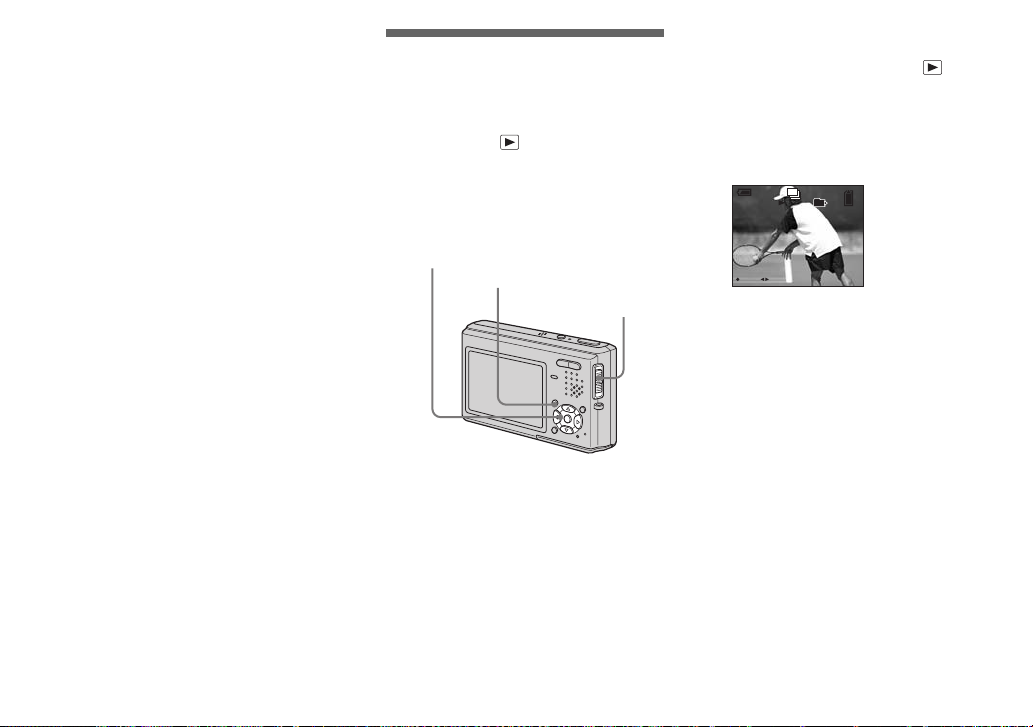
To cancel rotation
Select [Cancel] in step 4 or 5, then press
z.
• You cannot rotate protected images, movies and
Multi Burst images.
• You may not be able to rotate images shot with
other cameras.
• When viewing images on a computer, the
image rotation information may not be
reflected depending on the application
software.
Playing back images
shot in Multi Burst
mode
Mode switch:
You can play back Multi Burst images
continuously or play them back frame by
frame. This function is used for checking
the image.
Control button
MENU
Mode switch
• When Multi Burst images are played back on a
computer or on a camera without the Multi
Burst function, the 16 frames you shot will be
displayed at the same time as part of one image.
• You cannot cut the Multi Burst image.
Playing back continuously
a Set the mode switch to .
b Select the Multi Burst image
with b/B.
The selected Multi Burst image is
played back continuously.
M
60
min
101
14/14
PAUSE BACK/NEXT VOLUME
10:30PM2004 1 1101-0014
To pause playback
Press z. To resume playback, press z
again. The playback starts from the frame
displayed on the LCD screen.
64
Page 71

Playing back frame by frame
— Jog playback
a Set the mode switch to .
b Select the Multi Burst image
with b/B.
The selected Multi Burst image is
played back continuously.
c Press z when the desired
frame is displayed.
“Step” appears.
M
60
min
101
Step
3/16
PLAY FRAME BACK/NEXT VOLUME
14/14
10:30
2004 1 1101-0014
PM
d Advance the frame with b/B.
B: A next frame is displayed. When
you keep and press B, the frame
advances.
b: A previous frame is displayed.
When you keep and press b, the
frame advances in the reverse
direction.
To return to the normal playback
Press z in step 4. The playback starts
from the frame displayed on the LCD
screen.
To delete shot images
When using this mode, you cannot delete
only certain frames. When you delete
images, all 16 of the frames are deleted at
the same time.
1 Display the desired Multi Burst image to
delete.
2 Press (Delete).
3 Select [Delete], then press z.
All of the frames are deleted.
Advanced still image viewing
65
Page 72
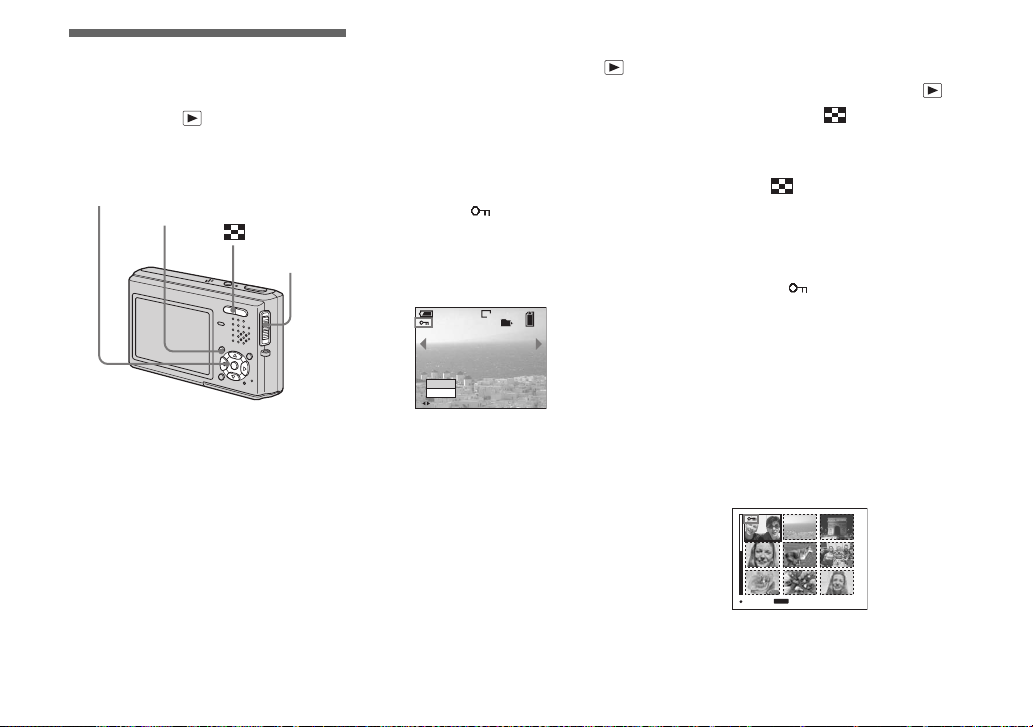
Still image editing
Protecting images
— Protect
Mode switch:
This function protects images against
accidental erasure.
Control button
MENU
Mode switch
• Note that when you format a “Memory Stick
Duo,” even protected images are deleted and
cannot be restored.
In single-image mode
a Set the mode switch to .
b Display the image you want to
protect with b/B.
c Press MENU.
The menu appears.
d Select (Protect) with b/B,
then press z.
The displayed image is protected. The
- (protect) indicator appears on the
image.
60min
VGA
101
2/9
Protect
Exit
BACK/NEXT
e To continue and protect other
images, select the desired
image with b/B, then press z.
To cancel the protection
Press z again in step 4 or 5. The indicator disappears.
In index (nine-image/
sixteen-image) mode
a Set the mode switch to ,
then press (Index) to
display the index (nine-image)
screen.
Press (Index) twice to display a
sixteen-image index screen.
b Press MENU.
The menu appears.
c Select (Protect) with b/B,
then press z.
d Select [Select] with b/B, then
press z.
e Select the image you want to
protect with v/V/b/B, then
press z.
The green - indicator appears on the
selected image.
MENU
TO NEXT
SELECT
66
f Repeat step 5 to protect other
images.
Page 73
g Press MENU.
h Select [OK] with B, then press
z.
The - indicator turns white. The
selected images are protected.
To exit the Protect function
Select [Cancel] in step 4 or select [Exit] in
step 8, then press z.
To cancel individual protection
Select the image to be unprotected with
v/V/b/B, then press z in step 5. The -
indicator turns gray. Repeat this operation
for all images that are to be unprotected.
Press MENU, select [OK], and then press
z.
To protect all images in the
folder
Select [All In This Folder] in step 4, and
press z. Select [On], then press z.
To cancel all protection of all
images in the folder
Select [All In This Folder] in step 4, and
press z. Select [Off], then press z.
Changing image size
— Resize
Mode switch:
You can change the image size of a
recorded image, and save it as a new file.
You can resize to the following sizes:
5M, 3M, 1M, VGA
The original image is retained even after
resizing.
Control button
MENU
Mode switch
a Set the mode switch to .
b Display the image you want to
resize with b/B.
c Press MENU.
The menu appears.
d Select (Resize) with b/B,
then press z.
e Select the desired size with v/
V, then press z.
The resized image is recorded in the
recording folder as the newest file.
To cancel resizing
Select [Cancel] in step 5.
• You cannot change the size of movies or Multi
Burst images.
• When you change from a small size to a large
size, the image quality deteriorates.
• You cannot resize to an image size of 3:2.
• When you resize a 3:2 image, the upper and
lower black portions will be displayed on the
image.
Still image editing
67
Page 74

Choosing images to
print
— Print (DPOF) mark
Mode switch:
You can use your camera to mark still
images that you want to have printed. This
function is convenient when you have
images printed at a shop that supports the
DPOF (Digital Print Order Format)
standard or using a printer that conforms to
the DPOF standard.
Control button
MENU
Mode switch
• You cannot mark movies.
• In E-mail mode, a print (DPOF) mark is
marked on the normal size image that is
recorded at the same time.
• When you mark images shot in Multi Burst
mode, all the images are printed on one image
divided into 16 frames.
• You cannot set the number of prints.
In single-image mode
a Set the mode switch to .
b Display the image you want to
mark with b/B.
c Press MENU.
The menu appears.
d Select (DPOF) with b/B,
then press z.
The mark is marked on the
displayed image.
60min
VGA
101
2/9
DPOF
Exit
BACK/NEXT
e To continue and mark other
images, display the desired
image with b/B, then press z.
To unmark the mark
Press z again in step 4 or 5. The
mark disappears.
68
Page 75

In index (nine-image/
sixteen-image) mode
a Set the mode switch to ,
then press (Index) to
display the index (nine-image)
screen.
Press (Index) twice to display a
sixteen-image index screen.
b Press MENU.
The menu appears.
c Select (DPOF) with B, then
press z.
d Select [Select] with b/B, then
press z.
• When marking marks, you cannot
select [All In This Folder].
e Select the image you want to
mark with v/V/b/B, then press
z.
The green mark appears on the
selected image.
f Repeat step 5 to mark other
images.
g Press MENU.
h Select [OK] with B, then press
z.
The mark turns white. The
mark setting is completed.
To unmark marks
Select the images to be unmarked with v/
V/b/B in step 5, then press z.
To unmark all the marks in
the folder
Select [All In This Folder] in step 4, then
press z. Select [Off], then press z.
Still image editing
To exit the mark function
Select [Cancel] in step 4, or select [Exit]
in step 8.
SELECT
MENU
TO NEXT
69
Page 76
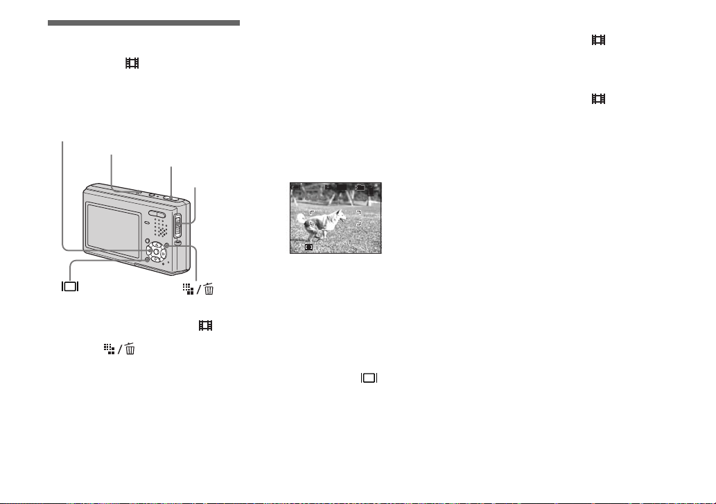
Shooting movies
Mode switch:
You can shoot movies with sound using
your camera.
Control button
Microphone
Shutter button
Mode switch
a Set the mode switch to .
b Press (Image Size).
The Image Size setup appears.
Enjoying movies
c Select the desired size with v/
V.
You can choose from [640(Fine)],
[640(Standard)] and [160].
• [640(Fine)] can be recorded only on
“Memory Stick PRO Duo.”
d Press the shutter button fully
down.
“REC” appears on the LCD screen and
the camera starts recording the image
and sound.
STD
60min
REC
101
640
00:00:02(00:10:48)
Recording stops when the “Memory
Stick Duo” is full.
e Press the shutter button fully
down again to stop recording.
Indicators during shooting
The screen indicators are not recorded.
Each time you press , the status of the
LCD screen changes as follows: Indicators
off t LCD backlight off t Indicators on.
A histogram is not displayed.
For a detailed description of the indicators,
see page 115.
Shooting close-ups (Macro)
Set the mode switch to and follow the
procedure on page 27.
Using the self-timer
Set the mode switch to and follow the
procedure on page 28.
• Do not touch the microphone during shooting
movies.
• You cannot use the following functions during
shooting movies:
– Changing the zoom scale
–Flash
– Inserting the date and time
• When you set the image size to [640(Fine)]
while connecting the A/V connecting cable to
A/V OUT (MONO) jack, the subject does not
appear on the LCD screen. The LCD screen
turns blue.
• For the recording time in each movie mode, see
page 101.
70
Page 77

Viewing movies on
the LCD screen
Mode switch:
You can view movies on the LCD screen
with sound from the speaker.
Control button
Speaker
Mode switch
a Set the mode switch to .
b Select the desired movie with
b/B.
Movies with the image size
[640(Fine)] or [640(Standard)] are
displayed on the full screen.
STD
60min
640
101
10/10
00:00:00
PLAY BACK/NEXT VOLUME
10:30PM2004 1 1101_0010
Movies with the image size [160] are
displayed a size smaller.
c Press z.
The movie and sound are played back.
During playback, B (Playback)
appears on the LCD screen.
STD
60min
640
101
10/10
00:00:03
Playback bar
STOP REV/CUE VOLUME
10:30PM2004 1 1101_0010
To stop playback
Press z again.
To advance or rewind the movie
Press b/B during playback.
To return to the normal playback, press z.
Indicators during viewing
movies
Each time you press , the status of the
screen changes as follows: Indicators off
t LCD backlight off t Indicators on.
A histogram is not displayed.
For a detailed description of the indicators,
see page 117.
• The procedure for viewing movies on a TV is
the same as that for viewing still images
(page 37).
• The movies recorded using earlier Sony models
may be also displayed a size smaller.
Enjoying movies
To adjust the volume
Press v/V to adjust the volume.
71
Page 78
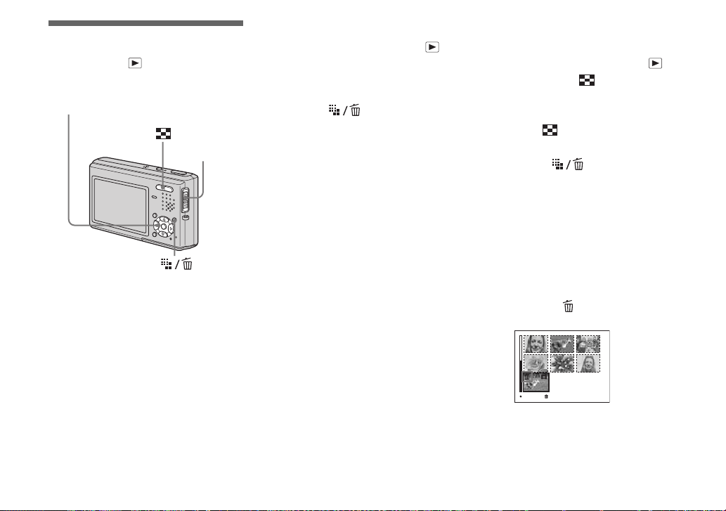
Deleting movies
Mode switch:
You can delete unwanted movies.
Control button
• You cannot delete protected movies.
• Note that you cannot restore deleted movies.
72
Mode switch
In single-image mode
a Set the mode switch to .
b Display the movie you want to
delete with b/B.
c Press (Delete).
The movie has not yet been deleted at
this point.
d Select [Delete] with v, then
press z.
The message “Access” appears, and
the movie has been deleted.
e To continue and delete other
movies, display the movie you
want to delete with b/B, and
repeat step
4.
To cancel deletion
Select [Exit] in step 4 or 5.
In index (nine-image/
sixteen-image) mode
a Set the mode switch to ,
then press (Index) to
display an index (nine-image)
screen.
Press (Index) twice to display a
sixteen-image index screen.
b Press (Delete).
The movie has not yet been deleted at
this point.
c Select [Select] with b/B, then
press z.
d Select the movie you want to
delete with v/V/b/B, then
press z.
The green (Delete) indicator
appears on the selected movie.
TO NEXTSELECT
The movie has not yet been deleted at
this point.
e Repeat step 4 to delete other
movies.
Page 79
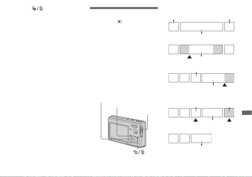
f Press (Delete).
g Select [OK] with B, then press
z.
The message “Access” appears, and
the movies have been deleted.
To cancel deletion
Select [Exit] in step 3 or 7.
To delete all images in the folder
Select [All In This Folder] in step 3, then
press z. Select [OK] with B, then press z.
To cancel deletion, select [Cancel] with b,
then press z.
Editing movies
Mode switch:
You can cut movies, or delete unnecessary
portions of movies. This is the
recommended mode to use when the
“Memory Stick Duo” capacity is
insufficient, or when you attach movies to
your e-mail messages.
The file numbers assigned when
movies are cut
The cut movies are assigned new numbers
and recorded as the newest files in the
selected recording folder. The original
movie is deleted, and that number is
skipped.
Control button
MENU
Mode switch
<Example> Cutting a movie numbered
101_0002
101_0001
1
1. Cutting scene A.
1
Divide point
2. Cutting scene B.
123 BA
3. Deleting scenes A and B if they are
unnecessary.
13
2
101_0002
2
101_0002
101_0004
101_0005
101_0004 101_0007
AB
101_0003
Divide
point
2
3
3AB
Enjoying movies
Delete Delete
4. Only the desired scenes remain.
13
101_0006
2
101_0006
73
Page 80

Cutting movies
a Set the mode switch to .
b Select the movie you want to
cut with b/B.
c Press MENU.
The menu appears.
d Select (Divide) with B, then
press z. Next, select [OK] with
v, then press z.
The playback of the movie starts.
e Decide on a cutting point.
Press z at the desired cutting point.
STD
60min
640
101
Divide
Dividing
Point
O K
Cancel
Exit
10/10
00:00:02
When you want to adjust the cutting
point, use [c/C] (frame forward/
rewind) and adjust the cutting point
using b/B. If you want to change the
cutting point, select [Cancel]. The
playback of the movie starts again.
f When you have decided on a
cutting point, select [OK] with
v/V, and press z.
g Select [OK] with v, then press
z.
The movie is cut.
To cancel cutting
Select [Exit] in step 5 or 7. The movie
appears on the LCD screen again.
• You cannot cut the following images.
– Still images
– Movie files not long enough to cut
– Protected movie files
• You cannot restore files once you cut them.
• The original movie is deleted when you cut it.
• The cut movies are recorded as the newest files
in the selected recording folder.
Deleting unnecessary
portions of movies
a Cut an unnecessary portion of
a movie (page 74).
b Display the portion of the
movie you want to delete.
c Press (Delete).
The movie has not yet been deleted at
this point.
d Select [Delete] with v, then
press z.
The movie currently displayed on the
LCD screen is deleted.
• Note that you cannot restore deleted portions of
movies.
74
Page 81

Enjoying images on your computer
Copying images to
your computer
— For Windows users
Recommended computer
environment
OS: Microsoft Windows 98, Windows
98SE, Windows 2000 Professional,
Windows Millennium Edition, Windows
XP Home Edition or Windows XP
Professional
The above OS must be installed at the
factory. Operation is not assured in an
environment upgraded to the operating
systems described above or in a multi-boot
environment.
CPU: MMX Pentium 200 MHz or faster
USB connector: Provided as standard
Display: 800 × 600 dots or more
High Color (16-bit color, 65,000 colors) or
more
• This camera conforms to USB 2.0.
• Use with a USB 2.0 (High-Speed USB)
compatible computer environment allows highspeed data transfer.
• If you connect two or more USB equipment to
a single computer at the same time, some
equipment, including your camera, may not
operate depending on the type of USB
equipment.
• Operations are not guaranteed when using a
USB hub.
• Operations are not guaranteed for all the
recommended computer environments
mentioned above.
USB mode
There are two modes for connecting to a
computer, [Normal] and [PTP]* modes.
The factory setting is the [Normal] mode.
This section describes the [Normal] mode
as an example.
* Compatible only with Windows XP. When
connected to a computer, only the data in the
folder selected by the camera is copied to the
computer. To select a folder, perform the
procedure on page 60.
Communication with your
computer
When your computer resumes from the
suspend or sleep mode, communication
between your camera and your computer
may not recover at the same time.
When a USB connector is not
provided on your computer
When neither a USB connector nor a
“Memory Stick” slot is provided, you can
copy images using an additional device. See
the Sony Website for details.
http://www.sony.net/
Contents of the CD-ROM
x USB Driver
This driver is needed in order to connect the
camera to a computer.
• When using Windows XP, you need not install
the USB driver.
x Image Transfer
This application is used to easily transfer
images from the camera to a computer.
x ImageMixer
This application is used to display and edit
images that are stored in a computer.
• The required operations may differ depending
on your OS.
• Close down all applications running on
the computer before installing the USB
driver and application.
• When using Windows XP or Windows 2000,
log on as Administrators.
• The display settings should be 800 × 600 dots
or more and High Color (16-bit color, 65,000
colors) or more. When set to less than 800 ×
600 dots or 256 colors or less, the model
selection screen does not appear.
Enjoying images on your computer
75
Page 82
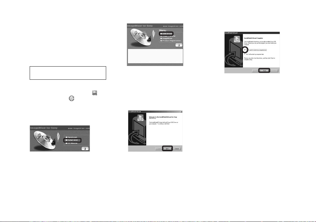
Installing the USB driver
When using Windows XP, you need not
install the USB driver.
Once the USB driver is installed, you need
not install the USB driver again.
a Start up your computer, and
insert the CD-ROM (supplied)
into the CD-ROM drive.
Do not connect your camera to
your computer at this time.
The model selection screen appears. If
it does not appear, double-click
(My Computer) t (ImageMixer)
in that order.
b Click [Cyber-shot] on the
model selection screen.
c Click [USB Driver] on the
installing menu screen.
The “InstallShield Wizard” screen
appears.
d Click [Next]. When the
“Information” screen appears,
click [Next].
e Click [Yes, I want to restart my
computer now], then click
[Finish].
Your computer restarts. Then, you can
establish USB connection.
76
The installing menu screen appears.
The USB driver installation starts.
When the installation is completed, the
screen informs you of completion.
Page 83
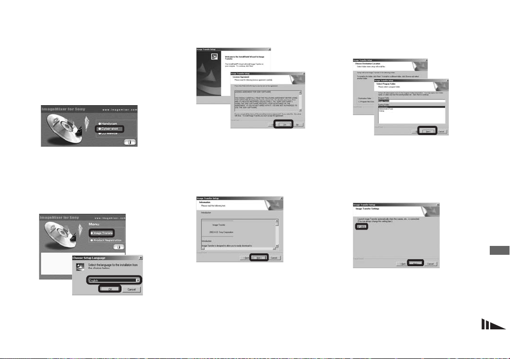
Installing “Image Transfer”
You can use the “Image Transfer” software
to copy images to your computer
automatically when you connect the camera
to your computer with the supplied USB
cable.
a Click [Cyber-shot] on the
model selection screen.
The installing menu screen appears.
b Click [Image Transfer] on the
installing menu screen.
Select the desired language,
then click [OK].
c Click [Next]. When “Licence
Agreement” screen appears,
click [Yes].
Read the agreement carefully. If you
accept the terms of the agreement,
proceed with the installation. The
“Information” screen appears.
d Click [Next].
e Select the folder to be
installed, then click [Next].
Select the program folder, then
click [Next].
Enjoying images on your computer
f Confirm if the checkbox is
checked on the “Image
Transfer Settings” screen,
then click [Next].
When the installation is completed, the
screen informs you of completion.
The “Welcome to the InstallShield
Wizard for Image Transfer” screen
appears.
• This section describes the English screen.
77
Page 84

g Click [Finish].
The “InstallShield Wizard” screen
closes. If you wish to continue with the
installation of “ImageMixer,” click
[ImageMixer] on the installing menu
screen and then follow the procedure.
• The USB driver is needed in order to use
“Image Transfer.” If the necessary driver is not
already installed on your computer, a screen
that asks if you want to install the driver will
appear. Follow the instructions that appear on
the screen.
Installing “ImageMixer”
You can use the “ImageMixer Ver. 1.5 for
Sony” software to copy, view and edit
images, and create video CDs. For details,
see the software’s help files.
a Click [ImageMixer] on the
installing menu screen.
Select the desired language,
then click [OK].
The “Welcome to the InstallShield
Wizard” screen appears.
• This section describes the English screen.
b Follow instructions on each
succeeding screen.
Install “ImageMixer” according to the
screen.
• When you use Windows 2000 or Windows XP,
install “WinASPI”.
• If DirectX8.0a or a later version is not installed
in your computer, the “Information” screen
appears. Follow the procedure on the screen.
c Restart your computer
according to the screen.
d Remove the CD-ROM.
78
Page 85
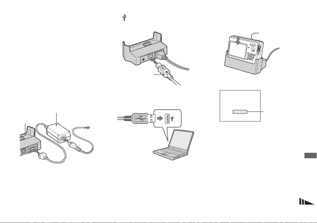
Connecting the camera to
your computer
a Turn on your computer.
b Insert the “Memory Stick Duo”
with the images you want to
copy into the camera.
• For further details on the “Memory Stick Duo,”
see page 19.
c Connect the USB cradle
(supplied) and the AC Adaptor
(supplied), and plug the
adaptor into a wall outlet (wall
socket).
AC Adaptor
USB cradle
1
• When you copy images to your computer using
the battery pack, copying may be failed or
cause data corruption by battery shutoff. We
recommend that you use the AC Adaptor.
To a wall outlet
(wall socket)
2
d Connect the USB cable to the
(USB) jack of the USB
cradle.
USB cable
e Connect the USB cable to your
computer.
• When you use a desktop computer, we
recommend that you connect the USB cable to
the USB connector on the rear panel.
• When using Windows XP, the AutoPlay wizard
automatically appears on the desktop. Proceed
to page 82.
f Connect the camera to the
USB cradle and turn on the
camera.
POWER
• Make sure the camera is securely connected to
the USB cradle.
USB Mode
Normal
Access
indicators*
“USB Mode Normal” appears on the
LCD screen of the camera. When a
USB connection is established for the
first time, your computer automatically
runs the used program to recognize the
camera. Wait for a while.
* During communication, the access
indicators turn red.
• If “USB Mode Normal” does not appear in step
6, confirm that [USB Connect] is set to
[Normal] on the Setup screen (page 107).
• Do not remove the camera from the USB
cradle during USB connection, as the
image data may be destroyed. To end
the USB connection, see the note P on
page 80.
Enjoying images on your computer
79
Page 86

P Disconnecting the USB
cable from your computer,
removing the “Memory Stick
Duo” from your camera or
turning off the power during
USB connection
For Windows 2000, Me or XP users
1 Double-click on the tasktray.
Double-click here
2 Click (Sony DSC), then click [Stop].
3 Confirm the device on the confirmation
screen, then click [OK].
4 Click [OK].
Step 4 is unnecessary for Windows XP
users.
5 Disconnect the USB cable, remove the
“Memory Stick Duo” or turn off the
power.
For Windows 98 or 98SE users
Confirm that the access indicators (page 79)
on the LCD screen are turned white and
carry out only step 5 above.
80
Copying images using
“Image Transfer”
— Windows 98/98SE/2000/Me
Connect the camera and your
computer with the USB cable and
the USB cradle.
“Image Transfer” launches and the images
are automatically copied to the computer.
When copying is complete, “ImageMixer”
automatically launches and images appear.
• Normally “Image Transfer” and “Date” folders
are created inside the “My Documents” folder,
and all of the image files recorded with the
camera are copied into these folders.
• You can change the “Image Transfer” settings
(page 81).
— Windows XP
Connect the camera and your
computer with the USB cable and
the USB cradle.
“Image Transfer” starts up automatically
and the images are automatically copied to
the computer.
Windows XP is set so that the OS AutoPlay
Wizard activates.
If you want to cancel the setting, follow the
procedure below.
a Click [Start], then click [My
Computer].
b Right-click [Sony
MemoryStick], then click
[Properties].
c Cancel the setting.
1 Click [AutoPlay].
2 Set [Content type] to [Pictures].
3 Check [Select an action to perform]
under [Actions], select [Take no
action], then click [Apply].
4 Set [Content type] to [Video files]
and proceed step 3. Set [Content
type] to [Mixed content] and
proceed step 3.
5 Click [OK].
The [Properties] screen closes.
The OS AutoPlay Wizard does not start up
automatically even if the USB connection is
made next time.
Page 87

Changing “Image Transfer”
settings
You can change “Image Transfer” settings.
Right-click the “Image Transfer” icon on
the tasktray, select [Open Settings]. The
settings you can set are as follows: [Basic],
[Copy], and [Delete].
Right-click here
When the “Image Transfer” starts, the
below window appears.
When you select [Settings] from the above
window, you can only change the [Basic]
setting.
Copying images without
using “Image Transfer”
— Windows 98/98SE/2000/Me
If you do not set to launch “Image Transfer”
automatically, you can copy images as
following procedure.
a Double-click [My Computer],
then double-click [Removable
Disk].
The contents of the “Memory Stick
Duo” inserted in your camera appear.
• This section describes an example of copying
images to the “My Documents” folder.
• When the “Removable Disk” icon is not shown,
see page 82.
• When using Windows XP, see page 82.
b Double-click [DCIM], then
double-click the folder which
contains the desired images.
The folder opens.
c Right-click the image, then
click [Copy].
d Double-click the “My
Documents” folder. Right-click
the inside of the folder, then
click [Paste].
The image files are copied to the “My
Documents” folder.
When an image with the same
file name exists in the copy
destination folder
The overwrite confirmation message
appears. When you overwrite the existing
image with the new one, the original file
data is deleted.
To change the file name
To copy an image file to the computer
without overwriting, change the file name
to the desired name. However, note that if
you change the file name, you may not be
able to play back that image with your
camera. To play back images with the
camera, perform the operation on page 85.
Enjoying images on your computer
81
Page 88

When a removable disk icon is not
shown
1 Right-click [My Computer], then click
[Properties].
The “System Properties” screen appears.
2 Display [Device Manager].
1 Click [Hardware].
2 Click [Device Manager].
• When using Windows 98, 98SE or Me, skip
step 1. Click [Device Manager] tab.
3 Delete “ Sony DSC” if it appears.
1 Right-click [ Sony DSC].
2 Click [Uninstall]. (When using
Windows 98, 98SE or Me, click
[Remove].)
The “Confirm Device Removal”
screen appears.
3 Click [OK].
The device is deleted.
Try the USB driver installation again using
the CD-ROM (supplied) (page 76).
— Windows XP
Copying images using the
Windows XP AutoPlay Wizard
a Make a USB connection
(page 79). Click [Copy pictures
to a folder on my computer
using Microsoft Scanner and
Camera Wizard], then click
[OK].
The “Scanner and Camera Wizard”
screen appears.
b Click [Next].
The images stored on the “Memory
Stick Duo” are displayed.
c Click the checkbox of images
that you do not want to copy to
your computer and remove the
checkmark, then click [Next].
The “Picture Name and Destination”
screen appears.
d Select a name and destination
for your pictures, then click
[Next].
Image copying starts. When the
copying is completed, the “Other
Options” screen appears.
e Select [Nothing. I’m finished
working with these pictures],
then click [Next].
The “Completing the Scanner and
Camera Wizard” screen appears.
f Click [Finish].
The wizard closes.
• To continue copying other images, follow the
procedure given under
disconnect the USB cable and reconnect it.
Then, perform the procedure from step 1
again.
P on page 80 to
82
Page 89
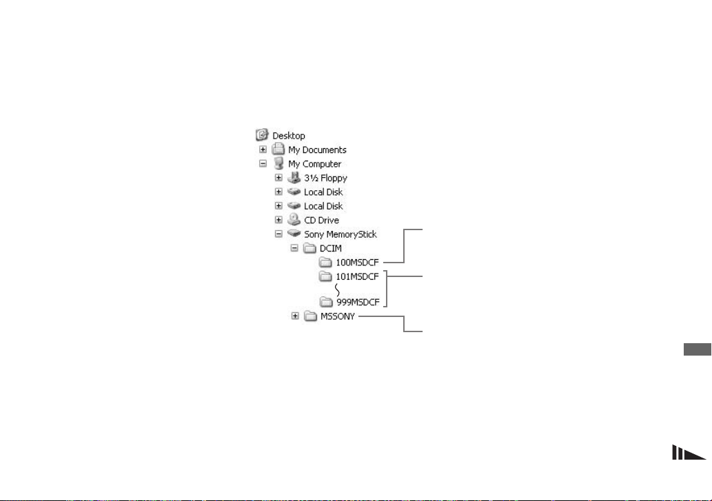
Viewing images on your
computer
a Click [Start] t [My
Documents] in that order.
The “My Documents” folder contents
are displayed.
• This section describes the procedure for
viewing copied images in the “My Documents”
folder.
• Except for Windows XP, double-click [My
Documents] on the desktop.
• You can use the “ImageMixer Ver. 1.5 for
Sony” software to view and edit images on your
computer. For details, see the software’s help
files.
b Double-click the desired image
file.
The image is displayed.
Image file storage
destinations and file names
Image files recorded with your camera are
grouped as folders in the “Memory Stick
Duo.”
Example: For Windows XP users
Folder containing image data recorded using a
camera without the folder creation function
Folder containing image data recorded with this
camera
When no new folders have been created, this is
only “101MSDCF”
Folder containing E-mail mode image data, movie
data and Voice mode audio data recorded using a
camera without the folder creation function
• Data in the “100MSDCF” or “MSSONY”
folders is for playback only, and your camera
cannot record images in these folders.
• For more information about the folder, see
page 45.
Enjoying images on your computer
83
Page 90

Folder File name File meaning
101MSDCF up to
999MSDCF
DSC0ssss.JPG
DSC0ssss.JPE
DSC0ssss.MPG
MOV0ssss.MPG
MOV0ssss.THM
• Still image files shot in
– Normal mode
– Exposure Bracket mode (page 52)
– Burst mode (page 55)
– Multi Burst mode (page 56)
• Still image files recorded simultaneously in
– E-Mail mode (page 57)
– Voice mode (page 58)
• Small-size image files shot in E-Mail mode (page 57)
• Audio files shot in Voice mode (page 58)
• Movie files (page 70)
• Index image file recorded simultaneously in movie mode (page 70)
• ssss stands for any number within the range from 0001 to 9999.
• The numerical portions of the following files are the same.
– A small-size image file shot in E-Mail mode and its corresponding image file
– An audio file shot in Voice mode and its corresponding image file
– A movie file shot in movie mode and its corresponding index image file
84
Page 91

Viewing image files once
copied to a computer with
your camera
When an image file copied to a computer no
longer remains in a “Memory Stick Duo,”
you can view that image again on your
camera by copying the image file in the
computer to a “Memory Stick Duo.”
• Step 1 is not necessary when the file name set
with your camera has not been changed.
• You may be unable to play back some images
depending on the image size.
• When an image file has been processed by a
computer or when the image file was recorded
using a model other than your camera, playback
on your camera is not guaranteed.
a Right-click the image file, then
click [Rename].
Change the file name to
“DSC0ssss.”
Enter a number from 0001 to 9999 for
ssss.
• An extension may be displayed depending on
the computer settings. The extension for still
images is JPG, and the extension for moving
images is MPG. Do not change the extension.
b Copy the file to the “Memory
Stick Duo” folder.
1 Right-click the image file, then
click [Copy].
2 Select the “DCIM” folder within
the [Removable Disk] or [Sony
MemoryStick] from [My
Computer].
3 Right-click the [sssMSDCF]
folder in the “DCIM” folder and
click [Paste]. sss is a number
from 100 to 999.
• When the overwrite confirmation message
appears, enter a different number in step 1.
• When there is no folder, first create a folder
with your camera and then copy the image file
(page 45).
Enjoying images on your computer
85
Page 92

Copying images to
your computer
— For Macintosh users
Recommended computer
environment
OS: Mac OS 9.1, 9.2 or Mac OS X (v10.0/
v10.1/v10.2)
The above OS must be installed at the
factory.
USB connector: Provided as standard
Display: 800 × 600 dots or more
32,000-color mode or more
• If you connect two or more USB equipment to
a single computer at the same time, some
equipment, including your camera, may not
operate depending on the type of USB
equipment.
• Operations are not guaranteed when using a
USB hub.
• Operations are not guaranteed for all the
recommended computer environments
mentioned above.
USB mode
There are two modes for connecting to a
computer, [Normal] and [PTP]* modes.
The factory setting is the [Normal] mode.
This section describes the [Normal] mode
as an example.
* Compatible only with Mac OS X. When
connected to a computer, only the data in the
folder selected by the camera is copied to the
computer. To select a folder, perform the
procedure on page 60.
Communication with your
computer
When your computer resumes from the
suspend or sleep mode, communication
between your camera and your computer
may not recover at the same time.
When a USB connector is not
provided on your computer
When neither a USB connector nor a
“Memory Stick” slot is provided, you can
copy images using an additional device. See
the Sony Website for details.
http://www.sony.net/
a Connecting your camera to
your computer
For details, see page 79.
Disconnecting the USB cable from your
computer, removing the “Memory Stick
Duo” from your camera or turning off
the power during a USB connection
Drag and drop the drive icon or the
“Memory Stick” icon to the “Trash” icon,
then remove the USB cable or “Memory
Stick Duo” or turn off the power.
• If you are using Mac OS X v10.0, remove the
USB cable, etc., after you have turned your
computer off.
b Copying images
1 Double-click the newly recognized icon
on the desktop.
The contents of the “Memory Stick
Duo” inserted in your camera appear.
2 Double-click [DCIM].
3 Double-click the folder containing the
desired image file.
4 Drag and drop the image files to the hard
disk icon.
The image files are copied to your hard
disk.
• See pages 83 and 84 for details about the image
file storage destinations and file names.
86
Page 93

c Viewing the images on your
computer
1 Double-click the hard disk icon.
2 Double-click the desired image file in
the folder containing the copied files.
The image file opens.
• Close down all applications running on
the computer before installing the
application.
• You can use the “ImageMixer Ver. 1.5 for
Sony” software to copy, view and edit images,
and create video CDs. See the operation manual
supplied with the CD-ROM for details about
the installation method, or see the software’s
help files for the operation method.
• When images cannot be displayed, increase the
virtual memory capacity of the computer.
• “ImageMixer” is not compatible with Mac OS
X.
• “Image Transfer” cannot be used with
Macintosh.
For Mac OS X users
If the “There is no application available to
open the document “DSC0ssss.JPE”.”
screen appears when you click an E-mail
mode image file, make the following
setting.
The screen display may differ depending on
the version.
1 Click [Choose Application...] at the
“There is no application available to
open the document
“DSC0ssss.JPE”.” screen.
2 Change “Show” from [Recommended
Applications] to [All Applications].
3 Select [QuickTime Player] from the
displayed list of applications, and click
[Open].
Enjoying images on your computer
87
Page 94
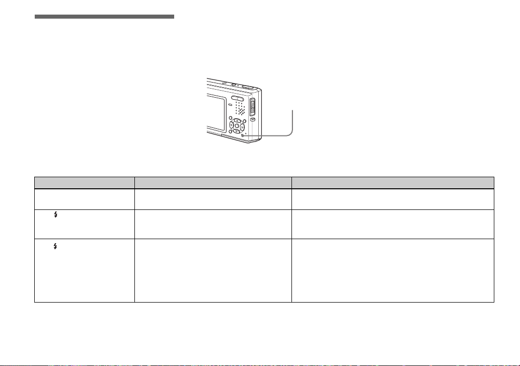
Troubleshooting
2 Should your camera still not work
Troubleshooting
If you experience trouble with your camera,
try the following solutions.
1 First check the items on the tables below.
properly, press the RESET button on the
lower right side of the control button
using a fine-tipped object, then turn on
the power again. (All the settings
including date and time are cleared.)
If code displays “C:ss:ss”
appear on the LCD screen, the
self-diagnosis display function is
working (page 99).
RESET button
Battery pack and power
Symptom Cause Solution
You cannot charge the
battery pack.
The /CHG lamp flashes
when charging a battery
pack.
The /CHG lamp does not
light up when charging a
battery pack.
• The camera is turned on.
• The battery pack is not installed correctly.
• The battery pack is not installed correctly.
• The battery pack has malfunctioned.
• The AC Adaptor is disconnected.
• The AC Adaptor has malfunctioned.
• The battery pack is not installed correctly.
• The battery pack is completely charged.
• The camera is not properly installed to the USB
cradle.
p Turn the camera off (page 16).
p Install the battery pack correctly (page 11).
p Install the battery pack correctly (page 11).
p Consult your Sony dealer or local authorized Sony service
facility.
p Properly connect the AC Adaptor (page 11).
p Consult your Sony dealer or local authorized Sony service
facility.
p Install the battery pack correctly (page 11).
—
p Properly install the camera (page 10).
3 Should your camera still not work
properly, consult your Sony dealer or
local authorized Sony service facility.
88
Page 95
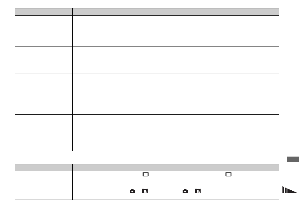
Symptom Cause Solution
The battery remaining
indicator is incorrect, or
sufficient battery
remaining indicator is
displayed but the power
runs out soon.
The battery pack runs
down too quickly.
You cannot turn on the
camera.
The power turns off
suddenly.
• You have used the camera for a long time in an
extremely hot or an extremely cold location.
• A deviation has occurred in the remaining
battery time.
• The battery pack is discharged.
• The battery pack is dead (page 111).
• You are shooting/viewing images in an
extremely cold location.
• The battery terminal is dirty.
• The battery pack is dead (page 111).
• The battery pack is not installed correctly.
• The AC Adaptor is disconnected.
• The AC Adaptor has malfunctioned.
• The battery pack is discharged.
• The battery pack is dead (page 111).
• The camera is not properly installed to the USB
cradle.
• If you do not operate the camera for about three
minutes when using a battery pack, the camera
turns off automatically to prevent wearing down
the battery (page 16).
• The battery pack is discharged.
• The camera is not properly installed to the USB
cradle.
p See page 111.
p Fully discharge and then charge the battery pack so that the
battery remaining indicator functions correctly (page 13).
p Install a charged battery pack (page 11).
p Replace the battery pack with a new one.
—
p Clean the battery terminal with a cotton swab, etc., and charge
the battery pack.
p Replace the battery pack with a new one.
p Install the battery pack correctly (page 11).
p Properly connect the AC Adaptor (page 15).
p Consult your Sony dealer or local authorized Sony service
facility.
p Install a charged battery pack (page 11).
p Replace the battery pack with a new one.
p Properly install the camera (page 10).
p Turn on the camera again (page 16) or use the AC Adaptor
(page 15).
p Install a charged battery pack (page 11).
p Properly install the camera (page 10).
Shooting still images/movies
Symptom Cause Solution
The LCD screen is not
turned on even when the
power is turned on.
The subject is not visible
on the LCD screen.
• The LCD backlight is turned off with in the
dark place.
• The mode switch is not set to or . p Set it to or (pages 22 and 70).
p Turn on the LCD backlight with (page 25).
Troubleshooting
89
Page 96

Symptom Cause Solution
The LCD screen turns
blue and the subject does
not appear when
recording movies.
The image is out of focus. • The subject is too close.
Zoom does not function. • You cannot change the zoom scale when
Optical zoom does not
function.
Digital zoom does not
function.
The image is too dark. • You are shooting a subject with a light source
The image is too bright. • You are shooting a spotlighted subject in a dark
Vertical streaks appear
when you are shooting a
very bright subject.
• The image size is set to [640(Fine)] while an A/
V connecting cable is connecte d to the A/V OUT
(MONO) jack.
• When shooting still images, (Camera) in the
menu is set to (Magnifying glass mode),
(Twilight mode), (Landscape mode) or
(Fireworks mode).
• The focus preset function is selected.
shooting movies.
• When shooting still images, (Camera) in the
menu is set to (Magnifying glass mode).
• [Digital Zoom] is set to [Off] on the Setup
screen.
• The image size is set to [5M] or [3:2] (only when
using the smart zoom).
• You are shooting in Multi Burst mode (only
when using the smart zoom).
behind the subject.
• The brightness of the LCD screen is too low.
• The LCD backlight is turned off.
location such as on a stage.
• The brightness of the LCD screen is too bright.
• The smear phenomenon is occurring. p This is not a malfunction.
90
p Disconnect the A/V connecting cable.
p Set the image size to other than [640(Fine)].
p Use close-up (Macro) function and set the lens position father
away from the subject than the shortest shooting distance
(page 27). Or, set (Camera) in the menu to
(Magnifying glass mode) and focus within the range of 1 cm to
20 cm (13/32 inch to 7 7/8 inches) from the subject (page 32).
p Set it to other settings (page 32).
p Cancel the function (page 49).
—
p Set it to other settings (page 32).
p Set [Digital Zoom] to [Smart] or [Precision] (pages 44 and 106).
p Set image size to other settings except [5M] and [3:2] (page 20).
p Set [Digital Zoom] to [Precision] (pages 44 and 106).
p Adjust the exposure (page 50).
p Adjust the brightness of the LCD screen (pages 44 and 107).
p Turn on the LCD backlight with (page 25).
p Adjust the exposure (page 50).
p Adjust the brightness of the LCD screen (pages 44 and 107).
Page 97
Symptom Cause Solution
Noise appears in the
image when you view the
LCD screen in a dark
place.
Your camera cannot
record images.
The flash does not work. • The mode switch is not set to .
The close-ups (Macro)
function does not work.
• The camera is functioning to increase the
visibility of the LCD screen by temporarily
brightening the image under conditions of low
illumination.
• No “Memory Stick Duo” has been inserted.
• The “Memory Stick Duo” is full.
• You are using a “Memory Stick Duo” with a
write-protect switch, and the write-protect
switch is set to the LOCK position.
• You cannot record images while charging the
flash.
• The mode switch is not set to when shooting
a still image.
• The mode switch is not set to when shooting
a movie.
• The image size is set to [640(Fine)] when
recording movies.
• The flash is set to (No flash).
• When shooting still images, (Camera) in the
menu is set to (Twilight mode) or
(Fireworks mode).
• (Camera) in the menu is set to
(Magnifying glass mode), (Landscape
mode), (Snow mode), (Beach mode) or
(High-speed shutter mode).
• [Mode] (REC Mode) in the menu is set to [Multi
Burst], [Exp Brktg], [Speed Burst] or [Framing
Burst].
• When shooting still images, (Camera) in the
menu is set to (Magnifying glass mode),
(Twilight mode), (Landscape mode) or
(Fireworks mode).
p There is no effect on the recorded image.
p Insert a “Memory Stick Duo” (page 19).
p Delete unnecessary images (pages 39 and 72).
p Change the “Memory Stick Duo.”
p Set it to the recording position (page 109).
—
p Set it to (page 22).
p Set it to (page 70).
p Insert a “Memory Stick PRO Duo” (pages 70 and 109).
p Set the image size to other than [640(Fine)].
p Set it to (page 22).
p Set the flash to auto (No indicator), (Forced flash) or
(Slow synchro) (page 29).
SL
p Set it to other settings (page 32).
p Set the flash to (Forced flash) (page 29).
p Set it to other settings.
p Set it to other settings (page 32).
Troubleshooting
91
Page 98

Symptom Cause Solution
The eyes of the subject
come out red.
The date and time are
recorded incorrectly.
The F value and shutter
speed flash when you
press and hold the shutter
button halfway down.
— p Set [Red Eye Reduction] on the Setup screen to [On] (pages 29
and 106).
• The date and time are not set correctly. p Set the correct date and time (pages 17 and 107).
• The exposure is incorrect. p Correct the exposure (page 50).
Viewing images
Symptom Cause Solution
Your camera cannot play
back images.
The image appears rough
right after playback starts.
The image does not
appear on the TV screen.
The image cannot be
played back on a
computer.
• The mode switch is not set to .
• The folder/file name has been changed on your
computer.
• Your camera cannot play back image files
copied from the hard disk o f your computer if the
image has been modified.
• The camera is set to USB mode.
• The image may appear rough right after
playback starts due to the image processing.
• The video output signal setting of your camera
on the Setup screen is incorrect.
• The connection is not correct.
• The USB jack is connected.
— p See page 93.
p Set it to (page 35).
p See page 85.
—
p Finish the USB connection (pages 80 and 86).
p This is not a malfunction.
p Change the setting (pages 44 and 107).
p Check the connection (page 37).
p Follow the procedure of the note P on page 80 (Windows) or
1 on page 86 (Macintosh) and disconnect the USB cable.
92
Page 99

Deleting/Editing Images
Symptom Cause Solution
Your camera cannot
delete an image.
You have deleted an
image by mistake.
The resizing function
does not work.
You cannot display a print
(DPOF) mark.
You cannot cut images. • The movie is not long enough to cut.
• The image is protected.
• You are using a “Memory Stick Duo” with a
write-protect switch, and the write-protect
switch is set to the LOCK position.
• Once you have deleted an image, you cannot
restore it.
• You cannot resize movies and Multi Burst
images.
• You cannot display print (DPOF) marks on
movies.
• Protected movie cannot be cut.
• Still images cannot be cut.
p Cancel the protection (page 66).
p Set it to the recording position (page 109).
p Marking - (protect) will prevent you from deleting images by
mistake (page 66).
p Accidental deletion can be prevented by setting the write-
protect switch of a “Memory Stick Duo” that has a write-protect
switch to the LOCK position (page 109).
—
—
—
p Cancel the protection (page 66).
—
Computers
Symptom Cause Solution
You do not know if the OS
of your computer is
compatible.
You cannot install the
USB driver.
— p Check “Recommended computer environment” (pages 75 and
86).
— p In Windows 2000, log on as Administrator (authorized
Administrators) (page 75).
Troubleshooting
93
Page 100

Symptom Cause Solution
Your computer does not
recognize your camera.
You cannot copy images. • The camera is not correctly connected to your
After making a USB
connection, “Image
Transfer” does not
automatically start.
The image cannot be
played back on a
computer.
• The camera is turned off.
• The battery level is low.
• You are not using the supplied USB cable.
• The USB cable is not connected firmly.
• The camera is not properly installed to the USB
cradle.
• [USB Connect] is set to [PTP] on the Setup
screen.
• The USB connectors on your computer are
connected to other equipment besides the
keyboard, the mouse and the USB cradle.
• The camera is not connected directly to your
computer.
• The USB driver is not installed.
• Your computer does not properly recognize the
device because you connected the camera and
your computer with the USB cable before you
installed the “USB Driver” from the CD-ROM
(supplied).
computer.
• You are not using the correct copy procedure for
your OS.
—
—
—
—
—
—
94
p Turn on the camera (page 16).
p Use the AC Adaptor (page 15).
p Use the supplied USB cable (page 79).
p Disconnect the USB cable from both the computer and the USB
cradle, and connect it aga in firmly. Make sure that “USB Mode”
is displayed on the LCD screen (page 79).
p Properly install the camera (page 10).
p Set it to [Normal] (pages 44 and 107).
p Disconnect all equipment other than the keyboard, the mouse
and the USB cradle from the USB connectors.
p Connect the camera directly to your computer without passing
through a USB hub or other device.
p Install the USB driver (page 76).
p Delete the incorrectly recognized device from your computer
(page 82), then install the USB driver (page 76).
p Connect the camera and your computer correctly using the USB
cable (page 79).
p Follow the designated copy proc edure for your OS (pages 81, 82
and 86).
p If you use the “Image Transfer” software, see page 80.
p If you are using the “ImageMixer Ver. 1.5 for Sony” application
software, click on HELP.
p Select [Launch Image Transfer automatically when your
camera, etc., is connected.] at [Basic] setting (page 81).
p Make a USB connection when the computer is turned on
(page 79).
p If you are using the “ImageMixer Ver. 1.5 for Sony” application
software, click on HELP.
p Consult the computer or software manufacturer.
 Loading...