

Page 1
DSC-P72
COVER
COVER
SECTION 2
DISASSEMBLY
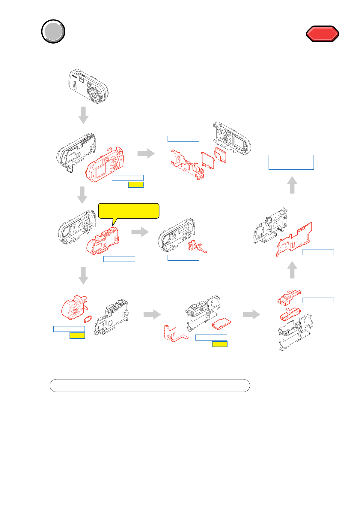
The following flow chart shows the disassembly procedure.
DISASSEMBLY
DISASSEMBLY
HELP
SY-85 board
service position
HELP
HELP
DISASSEMBLY
HELP
Discharging the Capacitor
DISASSEMBLY
DISASSEMBLY
DISASSEMBLY
DISASSEMBLY
DISASSEMBLY
HELP
PROCEDURE OF REMOVING SY-85 BOARD (SERVICE POSITION)
1 2-1. CABINET (R) BLOCK ASSEMBLY .................................................
2 2-2. BLOCK LIGHT GUIDE PLATE, LCD MODULE,
CONTROL SWITCH BLOCK (SW-391), LITHIUM BATTERY .......
3 2-3. MAIN BLOCK ASSEMBLY .............................................................
4 2-4. UNIT PARTS (UA-002) ..................................................................
5 2-5. VIDEO LENS (ED02D), CCD BLOCK ASSEMBLY ........................
6 2-6. MEMORY STICK CONNECTOR, JK BLOCK (JK-252) .................
7 2-7. CONTROL SWITCH BLOCK (RL-059), ST-82 BOARD .................
8 2-8. SY-85 BOARD ................................................................................
(page 2-2)
(page 2-3)
(page 2-4)
(page 2-4)
(page 2-5)
(page 2-6)
(page 2-6)
(page 2-7)
2-1
Page 2
DSC-P72
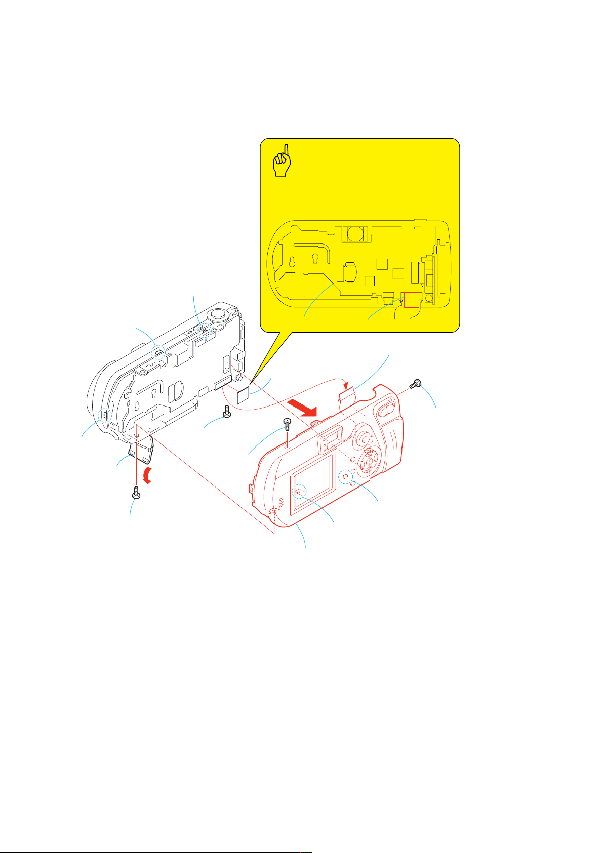
NOTE: F ollo w the disassembly procedure in the numerical order given.
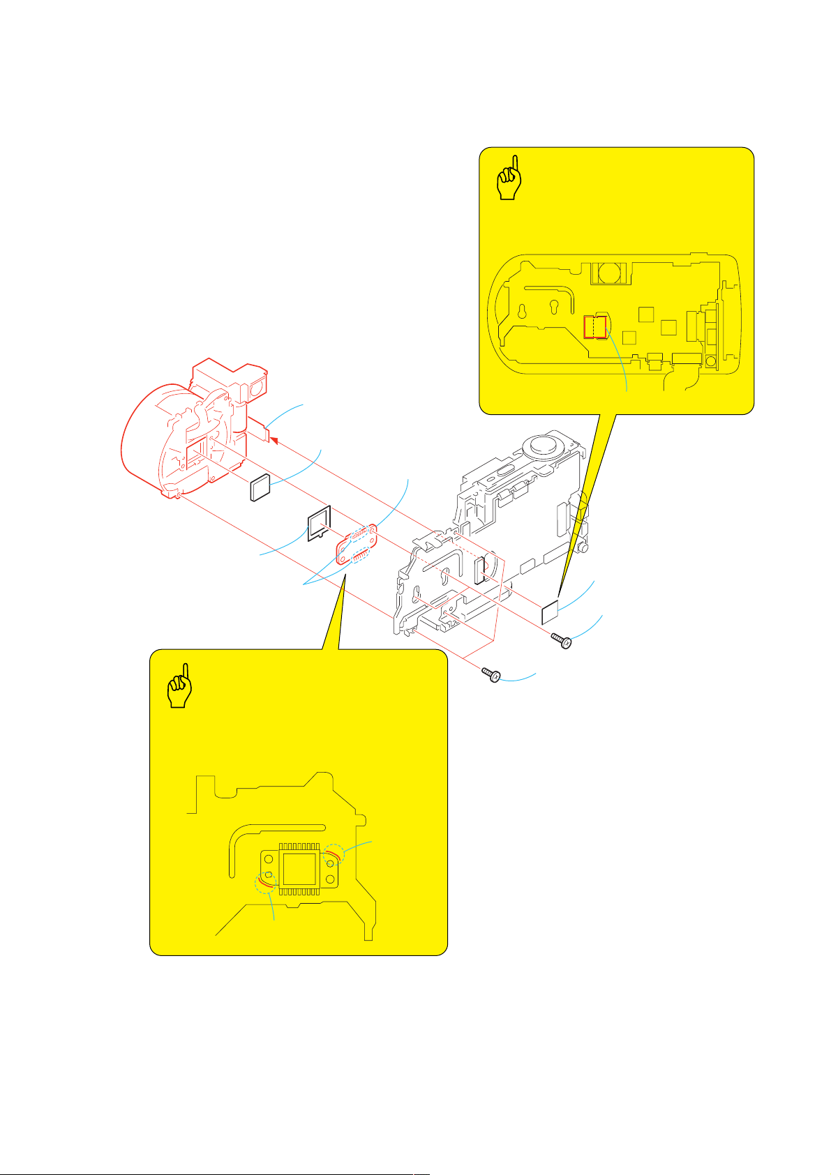
2-1. CABINET (R) BLOCK ASSEMBLY
Attach the Tape (Y) as shown in the illustration.
6
Claw
Caution
8
Claw
4
Open the
MS lid.
7
Claw
5
lock ace, p2
3
Screw (M2 × 4),
lock ace, p2
Screw (M2 × 4),
2
Screw (M2 × 4),
lock ace, p2
qa
Tape (Y)
Tape (Y)SY-85 board
qs
Control switch block (SW-391)(39P)
q;
Claw
9
Claw
qd
Cabinet (rear) block assembly
1
Screw (M2 × 4),
lock ace, p2
2-2
Page 3
DSC-P72
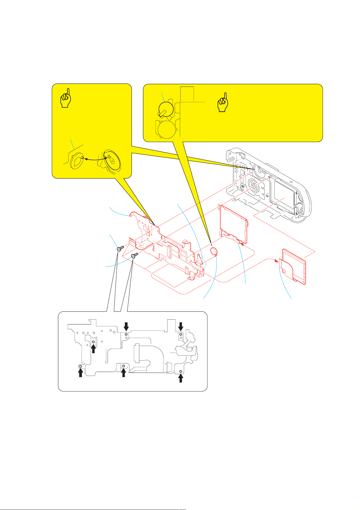
2-2. BLOCK LIGHT GUIDE PLATE, LCD MODULE, CONTROL SWITCH BLOCK (SW-391),
LITHIUM BATTERY
Lithium battery
Caution
When installing it,
align the switch position
as shown.
Control switch block (SW-391)
5
Control switch block (SW-391)
1
Four tapping screws
(M1.7 × 4)
2
Two tapping screws
(M1.7 × 4)
6
Remove soldering
from the two points.
Caution
Danger of explosion if batteryis incorrectly replaced.
Replace only with the same or equivalent type.
7
Lithium battery
3
Block light guide plate
(6P)
4
LCD module (ACX309AKB-2) (24P)
2-3
Page 4
DSC-P72
2-3. MAIN BLOCK ASSEMBLY
2
Two claws
Caution
The power supply capacitor of the Flash unit is
charged to the voltage as high as 300 V at a
maximum. The high voltage is not discharged
even after the main power of the machine is
simply turned off and the charged potential still
remains.
Discharge the residual voltage by referring to
Service Note (page 1-1).
Capacitor
1
Parts unit (UA-002)
(10P)
3
2-4. UNIT PARTS (UA-002)
Main block assembly
Shorting jig
Ω
/ 1w)
(1k
Flash unit
ST-82 B0ARD
2
Two c
laws
2-4
3
Unit parts
(UA-002)
1
Tapping screw, p2
(1.7 × 5)
Page 5
2-5. VIDEO LENS (ED02D), CCD BLOCK ASSEMBLY
Attach the Tape (Y) as shown in the illustration.
DSC-P72
Caution
4
Video lens (ED02D) (27P)
5
Optical filter block
8
CCD block assembly
6
Seal rubber (DQ)
7
Remove the solderings.
Caution
When installing the CCD block assy,
align the CCD block assembly with the mark as shown
in the illustration.
Tape (Y)
1
Tape (Y)
3
Two tapping screws, p2
(1.7
2
Three tapping screws
×
(1.7
4)
×
5)
mark
mark
2-5
Page 6
DSC-P72
r
d
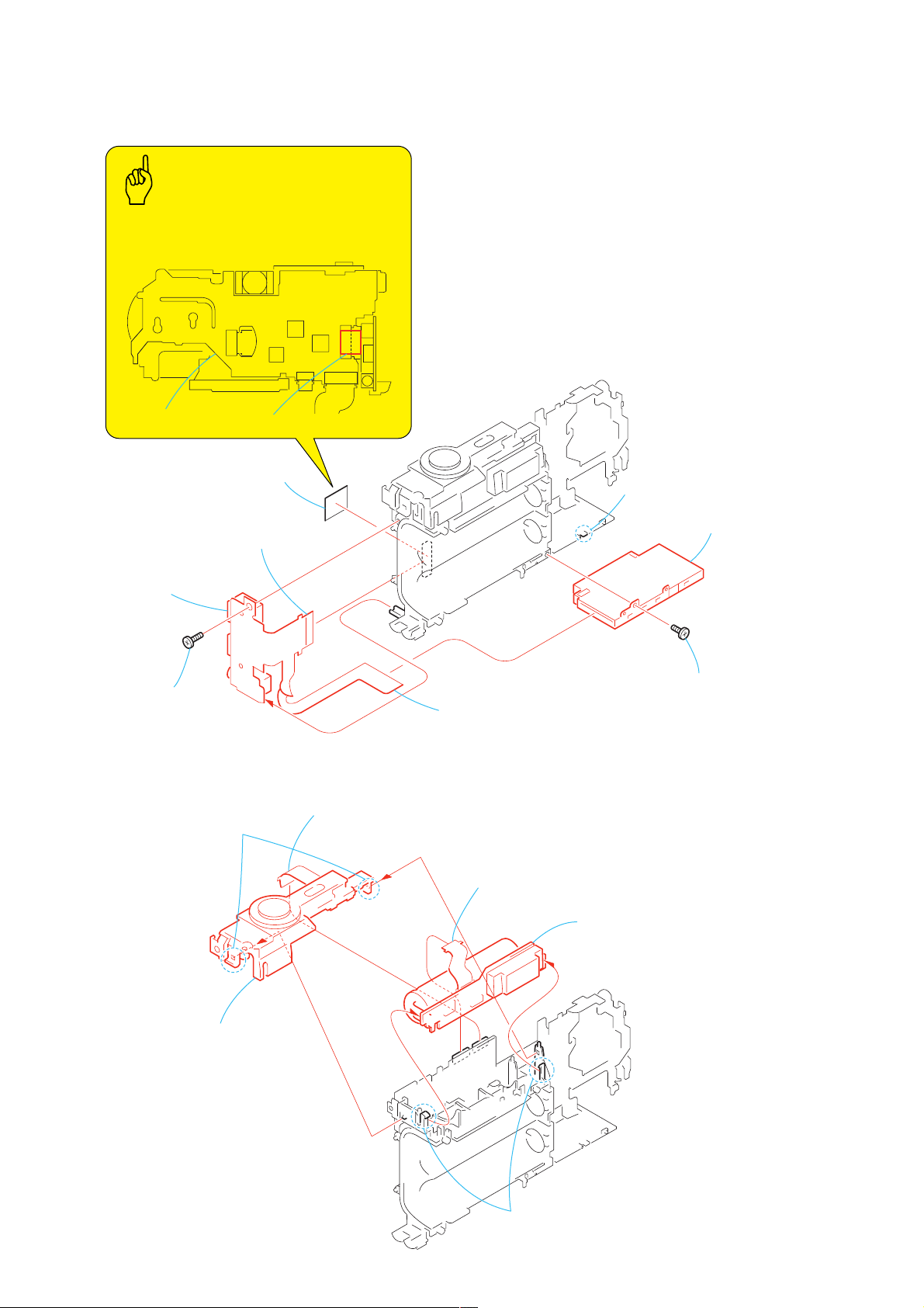
2-6. MEMORY STICK CONNECTOR, JK BLOCK (JK-252)
Caution
Attach the Tape (Y) as shown in the illustration.
8
JK block (JK-252)
5
Tapping screw, p2
(1.7
SY-85 board
7
JK block (JK-252) (39P)
×
5)
6
Tape (Y)
Tape (Y)
3
JK block (JK-252) (10P)
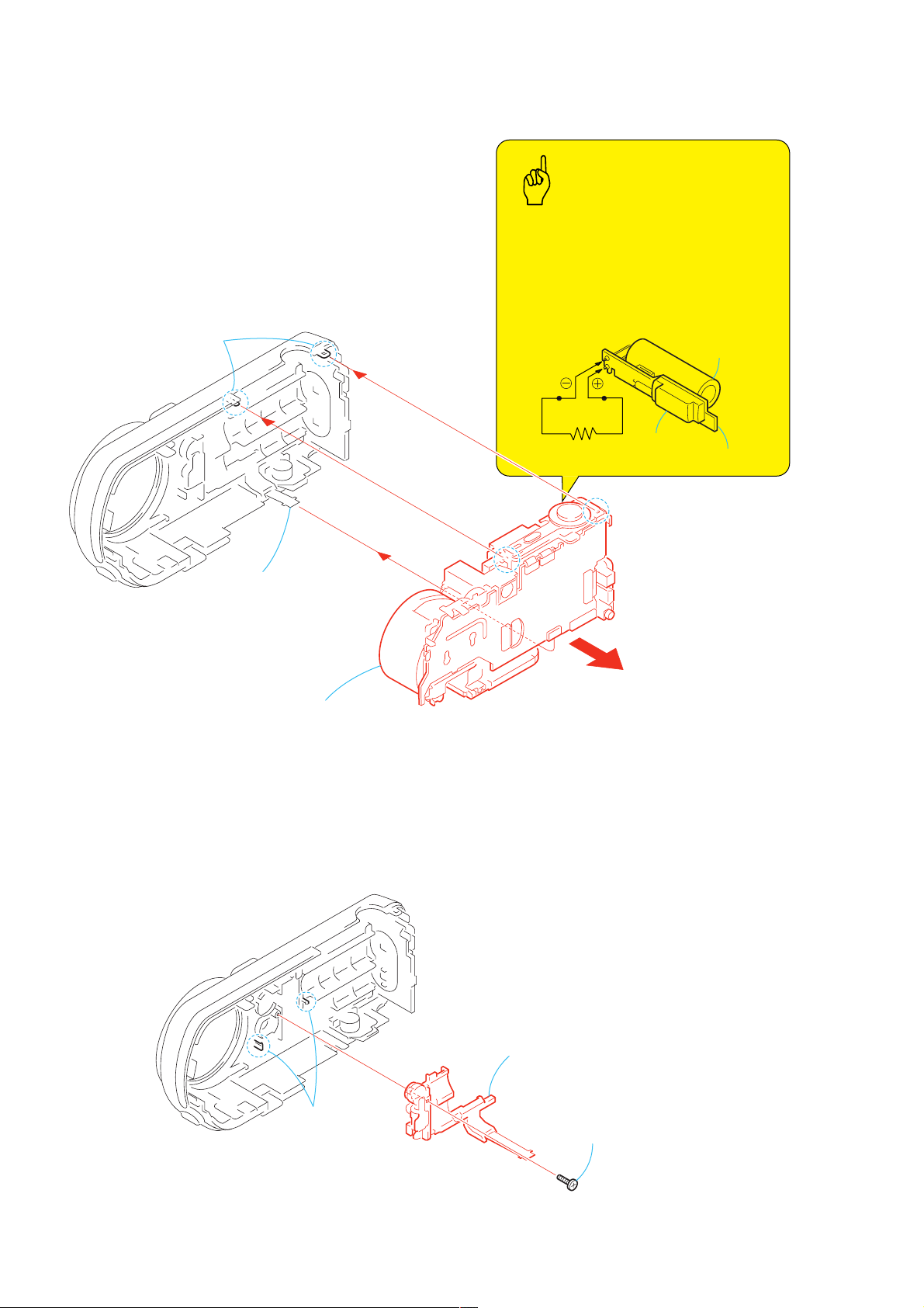
2-7. CONTROL SWITCH BLOCK (RL-059), ST-82 BOARD
2
Control switch block (RL-059)(10P)
1
Two claws
2
Claw
4
Memory stick connecto
1
Tapping screw
(1.7
×
4)
3
Control switch block
(RL-059)
2-6
5
FP-643 flexible board
(12P)
4
Two claws
6
ST-82 boar
Page 7

2-8. SY-85 BOARD
)
DSC-P72
Caution
When removing the harness,
be sure to pull the harness up at the
right angle with the board while pressing
down the connector on the circuit board.
Connector
2
Battery holder
(with terminal)
(4P)
3
SY-85 board
1
Four screws(M2 × 3
2-7
Page 8

DSC-P72
N
[SERVICE POSITION (SY-85 BOARD)]
Cabinet (rear) block assembly
(39P)
Memory stick connector
(10P)
JK block
(JK-252)
AC power
adaptor
AC I
CN706
CN201
(10P)
Unit parts(UA-002)
Video lens (ED02D)
“ Never remove the lens unless removal
is required at the event of checking the
CCD imager and others.’’
(27P)
SY-85 board
PROCEDURE OF REMOVING SY-85 BOARD (SERVICE POSITION)
1 2-1. CABINET (R) BLOCK ASSEMBLY .................................................
2 2-2. BLOCK LIGHT GUIDE PLATE, LCD MODULE,
CONTROL SWITCH BLOCK (SW-391), LITHIUM BATTERY ........
3 2-3. MAIN BLOCK ASSEMBLY .............................................................
4 2-4. UNIT PARTS (UA-002) ..................................................................
5 2-5. VIDEO LENS (ED02D), CCD BLOCK ASSEMBLY ........................
6 2-6. MEMORY STICK CONNECTOR, JK BLOCK (JK-252) .................
7 2-7. CONTROL SWITCH BLOCK (RL-059), ST-82 BOARD .................
8 2-8. SY-85 BOARD ................................................................................
CN702
CN705
(10P)
Control switch block (RL-059)
(page 2-2)
(page 2-3)
(page 2-4)
(page 2-4)
(page 2-5)
(page 2-6)
(page 2-6)
(page 2-7)
(39P)
CN701
CN704
(12P)
DC jack
ST-82 board
2-9. FLASH UNIT
2
Flash unit
2-8
1
Remove soldering
from the two points.
Page 9

2-10.CIRCUIT BOARDS LOCATION
ST-082
DSC-P72
SY-085
Board Name Function
SY-085 CCD IMAGER, CAMERA A/D CONVERTER, LENS DRIVE,
CAMERA DSP, VIDEO AMP, SH DSP, CLK GEN., FRONT CONTROL,
AUDIO I/O, LCD DRIVE, TIMING GEN., DC IN, DC-DC CONVERTER.,
CONNECTOR
ST-082 FLASH DRIVE
2-9
Page 10

DSC-P72
K
2-11.FLEXIBLE BOARDS LOCATION
The flexible boards contained in the video lens are not shown.
CONTROL SWITCH BLOCK
(SW-391)
UNIT PARTS (UA-002)
CONTROL SWITCH BLOC
(RL-059)
FP-643
JK BLOCK
(JK-252)
2-10E
Page 11

Sheet attachment positions and procedures of processing the flexible boards/harnesses are shown.
MAIN BLOCK SECTION
DSC-P72
17/Feb/2003. Update
HELP
SY-85 board
SY-85 board Tape (Y)
Caution B (280) label
Caution A (280) label
Busteraid 280
SY-85 board
SY-85 board
HELP
Page 12

DSC-P72
CABINET (REAR) BLOCK SECTION
CABINET (REAR) BLOCK SECTION
COVER
COVER
NOTE
NOTE
5. REPAIR PARTS LIST
NOTE: Characters A to Z of the electrical parts list indicate location of exploded views in which the desired part is shown.
Link
Link
CABINET (FRONT) SECTION
CABINET (FRONT) SECTION
Link
Link
EXPLODED VIEWS
EXPLODED VIEWS
A
MAIN BLOCK SECTION
MAIN BLOCK SECTION
ACCESSORIES
ELECTRICAL PARTS LIST
ELECTRICAL PARTS LIST
AA
ST-82 BOARDSY-85 BOARD
ST-82 BOARDSY-85 BOARD
ACCESSORIES
Page 13

5. REPAIR PARTS LIST
COVER
COVER
NOTE:
• -XX, -X mean standardized parts, so they may have some differences from
the original one.
• Items marked “*” are not stocked since they are seldom required for routine
service. Some delay should be anticipated when ordering these items.
• The mechanical parts with no reference number in the exploded views are not
supplied.
• Due to standardization, replacements in the parts list may be different from
the parts specified in the diagrams or the components used on the set.
• CAPACITORS:
uF: µF
• COILS
uH: µH
• RESISTORS
All resistors are in ohms.
METAL: metal-film resistor
METAL OXIDE: Metal Oxide-film resistor
F: nonflammable
• SEMICONDUCTORS
In each case, u: µ, for example:
uA...: µA... , uPA... , µPA... ,
uPB... , µPB... , uPC... , µPC... ,
uPD..., µPD...
• Abbreviation
CND : Canadian model
AUS : Australian model
JE : Tourist model
CH : Chinese model
KR : Korea model
HK : Hong Kong model
J : Japanese model
5. REPAIR PARTS LIST
DSC-P72
When indicating parts by reference number,
please include the board name.
The components identified by mark 0 or
dotted line with mark 0 are critical for safety.
Replace only with part number specified.
Les composants identifiés par une marque
0 sont critiques pour la sécurité.
Ne les remplacer que par une pièce portant
le numéro spécifié.
5-1
Page 14

COVER
COVER
5-1. EXPLODED VIEWS
5-1-1. CABINET (FRONT) SECTION
ns : not supplied
5. REPAIR PARTS LIST
5. REPAIR PARTS LIST
DSC-P72
A
1
Cabinet (rear) block assembly
(See page 5-5)
1
Main block assembly
(See page 5-4)
B
A
4
3
6
B
6
2
1
ns
5
1
Ref. No. Part No. Description Ref. No. Part No. Description
1 3-968-729-71 SCREW (M2), LOCK ACE, P2
2 3-082-168-01 WINDOW, OVF
3 3-080-977-01 TRIPOD
4 X-3953-159-1 CABINET (FRONT) ASSY
5 1-477-810-11 UNIT PARTS (UA-002)
6 3-080-204-21 SCREW, TAPPING, P2
5-3
Page 15

DSC-P72
COVER
COVER
5-1-2. MAIN BLOCK SECTION
ns : not supplied
5. REPAIR PARTS LIST
5. REPAIR PARTS LIST
53
ns
54
51
56
J102
A
55
J101
CN101
52
57
67
B
ns
C
A
B
ns
ns
51
60
ns
59
53
IC351
ns
66
62
ns
ns
58
63
BT901
C
61
65
64
Be sure to read “Precautions upon replacing CCD imager”
on page 4-7 when changing the CCD imager.
(Note) See page 2-5 of when installing the CCD block assy.
Ref. No. Part No. Description Ref. No. Part No. Description
51 3-078-890-11 SCREW, TAPPING
52 1-815-853-21 MEMORY STICK CONNECTOR
53 3-080-204-21 SCREW, TAPPING, P2
54 1-477-859-11 JK BLOCK (JK-252)
55 A-7078-600-A ST-82 (S) BOARD, COMPLETE
56 1-687-751-11 FP-643 FLEXIBLE BOARD
57 1-477-806-11 CONTROL SWITCH BLOCK (RL-059)
58 A-7078-684-A SY-85 BOARD, COMPLETE (SERVICE)
59 3-078-889-11 SCREW (M1.7)
60 3-075-085-01 RUBBER (DQ), SEAL
61 1-758-916-11 FILTER BLOCK, OPTICAL
62 3-082-136-01 SHEET, SHIELD
63 3-081-034-01 FRAME, LENS
64 1-758-925-11 LENS, VIDEO (ED02D)
65 3-076-569-01 PLATE, LIGHT INTERCEPTION
66 3-083-057-01 CUSHION (ISB), ELECTROSTATIC
0 67 1-477-803-11 FLASH UNIT
BT901 1-756-347-11 HOLDER, BATTERY(WITH TERMINAL)
CN101 1-794-962-11 CONNECTOR, SQUARE TYPE(USB 5P)
IC351 A-7013-723-A CCD BLOCK ASSY (CCD IMAGER)
J101 1-817-331-11 DC JACK 5P (DC IN)
J102 1-569-950-31 JACK (SMALL TYPE)(A/V OUT(MONO))
(Note)
5-4
Note :
The components identified by
mark 0 or dotted line with mark
0 are critical for safety.
Replace only with part number
specified.
Note :
Les composants identifiés par
une marque 0 sont critiques
pour la sécurité.
Ne les remplacer que par une
pièce portant le numéro spécifié.
Page 16

5. REPAIR PARTS LIST
COVER
COVER
5. REPAIR PARTS LIST
5-1-3. CABINET (REAR) BLOCK SECTION
ns : not supplied
DSC-P72
104
103
101
102
BT100
A
B
: For the installation position of BT100 (Lithium battery), refer to page 2-3
B
ns
LCD901
ND901
A
CAUTION :
Danger of explosion if battery is incorrectly replaced.
Replace only with the same or equivalent type.
Ref. No. Part No. Description Ref. No. Part No. Description
101 3-078-890-11 SCREW, TAPPING
102 1-477-809-11 CONTROL SWITCH BLOCK (SW-391)
103 X-3953-17901 CABINET (REAR) ASSY
104 3-080-985-01 COVER, JACK
0 ND901 1-477-762-11 BLOCK LIGHT GUIDE PLATE (1.5)
LCD901 8-753-052-23 ACX309AKB-J
Note :
The components identified by
mark 0 or dotted line with mark
0 are critical for safety.
Replace only with part number
specified.
5-5
Note :
Les composants identifiés par
une marque 0 sont critiques
pour la sécurité.
Ne les remplacer que par une
pièce portant le numéro spécifié.
Page 17

DSC-P72
SY-85 ST-82
5-2. ELECTRICAL PARTS LIST
Ref. No. Part No. Description Ref. No. Part No. Description
A-7078-684-A SY-85 BOARD, COMPLETE (SERVICE)
******************************
************************************************************
R506 1-218-958-11 RES-CHIP 2.7K 5% 1/16W
R507 1-218-965-11 RES-CHIP 10K 5% 1/16W
R508 1-218-940-11 RES-CHIP 82 5% 1/16W
R509 1-218-961-11 RES-CHIP 4.7K 5% 1/16W
R510 1-216-805-11 METAL CHIP 47 5% 1/16W
Electrical parts list of the SY-085 board
are not shown.
Pages fr om 5-6 to 5-11 are not shown.
A-7078-600-A ST-82 (S) BOARD, COMPLETE
************************
0 1-477-803-11 FLASH UNIT
< CAPACITOR >
C503 1-137-710-11 CERAMIC CHIP 10uF 20% 6.3V
C504 1-137-710-11 CERAMIC CHIP 10uF 20% 6.3V
C505 1-127-715-91 CERAMIC CHIP 0.22uF 10% 16V
C506 1-125-837-91 CERAMIC CHIP 1uF 10% 6.3V
C507 1-125-777-11 CERAMIC CHIP 0.1uF 10.00% 10V
C508 1-100-542-11 CAP, ELECT 135uF
C509 1-137-723-21 CERAMIC CHIP 0.047uF 10% 250V
C510 1-137-710-11 CERAMIC CHIP 10uF 20% 6.3V
C511 1-137-710-11 CERAMIC CHIP 10uF 20% 6.3V
C512 1-125-777-11 CERAMIC CHIP 0.1uF 10.00% 10V
< CONNECTOR >
CN501 1-816-644-11 FFC/FPC CONNECTOR (LIF) 12P
< DIODE >
R511 1-216-857-11 METAL CHIP 1M 5% 1/16W
0 R512 1-216-121-11 RES-CHIP 1M 5% 1/10W
< TRANSFORMER >
0 T501 1-437-737-11 TRANSFORMER, DC-DC CONVERTER
************************************************************
D501 8-719-073-01 DIODE MA111-(K8).S0
0D502 6-500-237-01 DIODE HAU160C030TP
< IC >
IC501 6-703-635-01 IC TND721MH5-S-TL-E
< COIL >
0L501 1-456-193-11 COIL, TRIGGER
< TRANSISTOR >
Q501 6-550-119-01 TRANSISTOR DTC144EMT2L
Q502 6-550-528-01 TRANSISTOR UPA650TT-E1-A
Q503 6-550-183-01 TRANSISTOR CPH3209-SONY-TL-E
Q504 8-729-056-01 TRANSISTOR MCH3405-TL-E
Q505 8-729-053-57 TRANSISTOR RN1902FE(TPLR3)
0Q506 8-729-053-74 TRANSISTOR CY25AAJ-8-T13
< RESISTOR >
R501 1-218-961-11 RES-CHIP 4.7K 5% 1/16W
R502 1-218-977-11 RES-CHIP 100K 5% 1/16W
R503 1-218-965-11 RES-CHIP 10K 5% 1/16W
R504 1-218-957-11 RES-CHIP 2.2K 5% 1/16W
R505 1-218-977-11 RES-CHIP 100K 5% 1/16W
5-12
Note :
The components identified by
mark 0 or dotted line with mark
0 are critical for safety.
Replace only with part number
specified.
Note :
Les composants identifiés par
une marque 0 sont critiques
pour la sécurité.
Ne les remplacer que par une
pièce portant le numéro spécifié.
Page 18

DSC-P72
(Page 2-3)
SECTION 2 DISASSEMBLY
2-2. BLOCK LIGHT GUIDE PLATE, LCD MODULE, CONTROL SWITCH BLOCK (SW-391),
LITHIUM BATTERY
Lithium battery
Caution
When installing it,
align the switch position
as shown.
Control switch block (SW-391)
5
Control switch block (SW-391)
1
Four tapping screws
×
(M1.7
2
Two tapping screws
(M1.7
4)
×
4)
6
Remove soldering
from the two points.
Caution
Danger of explosion if batteryis incorrectly replaced.
Replace only with the same or equivalent type.
7
Lithium battery
3
Block light guide plate
(6P)
4
LCD module (ACX309AKB-2) (24P)
— 2 —
Page 19

(Page 5-5)
SECTION 5 REPAIR PARTS LIST
5-1. EXPLODED VIEWS
5-1-3. CABINET (REAR) BLOCK SECTION
ns : not supplied
DSC-P72
104
103
B
LCD901
ND901
A
101
102
BT100
A
B
: For the installation position of BT100 (Lithium battery), refer to page 2-3
CAUTION :
Danger of explosion if battery is incorrectly replaced.
Replace only with the same or equivalent type.
Ref. No. Part No. Description Ref. No. Part No. Description
101 3-078-890-11 SCREW, TAPPING
102 1-477-809-11 CONTROL SWITCH BLOCK (SW-391)
103 X-3953-17901 CABINET (REAR) ASSY
104 3-080-985-01 COVER, JACK
0 ND901 1-477-762-11 BLOCK LIGHT GUIDE PLATE (1.5)
LCD901 8-753-052-23 ACX309AKB-J
ns
— 3 —
Note :
The components identified by
mark 0 or dotted line with mark
0 are critical for safety.
Replace only with part number
specified.
Note :
Les composants identifiés par
une marque 0 sont critiques
pour la sécurité.
Ne les remplacer que par une
pièce portant le numéro spécifié.
Page 20

DSC-P72
SECTION 5 REPAIR PARTS LIST
5-2. ELECTRICAL PARTS LIST
(Page 5-13E)
Checking supplied accessories.
Make sure that the following accessories are supplied with your camcorder.
: Added portion.
Power cord (1)(AUS model)
0
1-696-819-11
Power cord (1)(AEP,E model)
0
1-769-608-11
Power cord (1)(CH model)
0
1-782-476-11
Power cord (1)(UK,HK model)
0
1-783-374-11
Power cord (1)(US,CND model)
0
1-790-107-22
Power cord (1)(JE,J model)
0
1-790-732-11
Power cord (1)(KR model)
0
1-776-985-11
CD-ROM (USB DRIVER) (1)
(SPVD-010)
(AEP,UK,E,HK,AUS, BR,
CH,JE,KR model)
3-078-942-03
CD-ROM (USB DRIVER) (1)
(SPVD-010 (I)) (US,CND,J model)
3-078-943-03
Battery charger (BC-CS2)(1)
(US,CND,JE,J model)
0
1-477-814-11
Battery charger (BC-CS2)(1)
(AEP,UK,E,HK,AUS, BR model)
0
1-477-814-21
Battery charger (BC-CS2)(1)
(CH, KR model)
0
1-477-814-31
Memory stick (1)
(MSA-16A)
(not supplied)
HR6 (size AA) Ni-MH
batteries
(not supplied)
Other accessories
3-080-877-01 MANUAL, INSTRUCTION (JAPANESE)(J)
3-080-877-11 MANUAL, INSTRUCTION (ENGLISH)
3-080-877-21 MANUAL, INSTRUCTION (FRENCH/GERMAN) (CND,AEP)
3-080-877-31 MANUAL, INSTRUCTION (SPANISH/PORTUGUESE)
3-080-877-41 MANUAL, INSTRUCTION (ITALIAN/DUTCH) (AEP)
3-080-877-51 MANUAL, INSTRUCTION (CHINESE) (E,HK,CH,JE,KR)
3-080-877-61 MANUAL, INSTRUCTION (RUSSIAN/SWEDISH) (AEP)
3-080-877-71 MANUAL, INSTRUCTION (ARABIC) (E)
3-080-877-81 MANUAL, INSTRUCTION (KOREAN) (KR)
(AEP,E,JE,KR)
Connection cord
(AV Cable 1.5m)(1)
1-824-111-11
Battery carrying case (1)
3-074-757-01
2P conversion adaptor (1)
(JE model)
1-569-007-12
• Abbreviation
CND : Canadian model
HK : Hong Kong model
AUS : Australian model
CH : Chinese model
Note :
The components identified by
mark 0 or dotted line with mark
0 are critical for safety.
Replace only with part number
specified.
Hand strap (1)
3-070-841-01
Cord with connector (1)
(USB 5P)
1-827-038-11
2P conversion adaptor (1)
(E model)
1-569-008-12
JE : Tourist model
KR : Korea model
BR : Brazilian model
J : Japanese model
Note :
Les composants identifiés par
une marque 0 sont critiques
pour la sécurité.
Ne les remplacer que par une
pièce portant le numéro spécifié.
9-876-229-82
Sony EMCS Co.
— 4 —
2003C1600-1
©2003.3
Published by DI Customer Center
 Loading...