

Page 1
DSC-P71/P71M
SERVICE MANUAL
Level 3
Ver 1.2 2002. 11
This service manual contains information for Japanese model as well.
SPECIFICATIONS
System
Image device
Effective pixels number of camera
Lens
Exposure control
White balanceAutomatic, Daylight, Cloudy,
Data formats Moving images: MPEG1
Recording media
Flash Recommended distance
Output connectors
VIDEO OUT jack
USB jack mini-B
LCD screen
LCD panel used
Total number of dots
8.93mm (1/1.8 type) color
CCD
Primary color filter
Approx. 3 210 000 pixels
3×zoom lens
f=8~24.0 mm (35 mm camera
conversion: 39 to 117mm)
F2.8~5.3
Automatic,
Scene Selection (3 mode)
Fluorescent, Incandescent
Still images: JPEG, GIF F(for Clip
Motion)
“Memory Stick”
0.5 to 3.8 m (1.6 to 12.5
0.5 to 2.5 m (1.6 to 8.2 ft) (T)
(when ISO sensitivity is set to Auto)
Minijack
1 Vp-p, 75 ohm, unbalanced, sync
negative
3.8 cm (1.5 type) TFT drive
123 200 (560x220) dots
ft) (W)
Power, etc.
Power AA nickel hydride batteries (2)
Power consumption (when recording)
Operating temperature range
Storage temperature range
Dimensions
Mass
BC-CS1 Ni-MH battery charger
Power requirements
Output voltage
Dimensions 70 ×29 ×74 mm (2
Mass Approx. 70g (2 oz)
Operating temperature range
2.4 V
AC-LS 1 AC p owe r ad apt or
(not supplied), 4.2 V
2.1W
0° to
+
40°C (32° to+104°F)
−
20° to +60°C (−4° to+140°F)
124.9 ×58 ×43.6 mm (5 ×2
1 3/4inches)
(W/H/D, protruding portions not
included)
284 g (10 oz) (camera, two batteries,
“Memory Stick” and wrist strap
included)
AC 100 to 240V 50/60Hz
2.2 W
DC 1.8V 180/110 mA 2
inches) (W/H/D)
0° to +40°C (32° to +104°F)
3
/
8
×
7
/8×1 3/16×3
US Model
DSC-P71/P71M
Canadian Model
AEP Model
UK Model
E Model
Hong Kong Model
Australian Model
Chinese Model
Korea Model
Tourist Model
Japanese Model
DSC-P71
AC-LS1 AC power adaptor (not
supplied)
Power requirements
Rated output voltage
External dimensions
Mass Approx. 180 g (6 oz)
Operating temperature range
Storage temperature range
Accessories
•Video connector cable (1)
•R6 (size AA) Ni-MH batteries (2)
•Ni-MH Battery charger (1)
•Power cord (mains lead) (1)
•USB cable (1)
•Wrist strap
•“Memory Stick” (16MB) (1)
•CD-ROM (USB driver: SPVD-008) (1)
•CD-ROM (for Customer registration) (1)
•Operation Instructions (1)
Design and specifications are subject to change
without notice.
AC 100 – 240 V, 50/60 Hz
DC 4.2 V , 1.5 A
105 ×36 ×56 mm (4
2 1/4)(W/H/D, protruding parts not
included)
(adaptor only)
0° to
+
40°C (32° to+104°F)
−
20° to+60°C (−4° to +140°F)
1
/4× ×
1 7/
16
DIGITAL STILL CAMERA
Page 2

DSC-P71/P71M
Table for differences of function
Model DSC-P71
US, Canadian, AEP, UK
Destination
Note: DSC-P71M is the same as DSC-P71 (US model) except packing materials.
Therefore, information about DSC-P71 (US model) in the text is applied.
E, J, Hong Kong,
Australian, Chinese,
Korea, Tourist
CAUTION
Use of controls or adjustments or performance
procedures other than those specified herein may
result in hazardous radiation exposure.
DSC-P71M
(Note)
US
SAFETY-RELATED COMPONENT WARNING!!
COMPONENTS IDENTIFIED BY MARK 0 OR DOTTED
LINE WITH MARK 0 ON THE SCHEMATIC DIAGRAMS
AND IN THE PARTS LIST ARE CRITICAL TO SAFE
OPERATION. REPLACE THESE COMPONENTS WITH
SONY PARTS WHOSE PART NUMBERS APPEAR AS
SHOWN IN THIS MANUAL OR IN SUPPLEMENTS PUBLISHED BY SONY.
SAFETY CHECK-OUT
After correcting the original service problem, perform the following
safety checks before releasing the set to the customer.
1. Check the area of your repair for unsoldered or poorly-soldered connections. Check the entire board surface for solder
splashes and bridges.
2. Check the interboard wiring to ensure that no wires are
“pinched” or contact high-wattage resistors.
3. Look for unauthorized replacement parts, particularly transistors, that were installed during a previous repair. Point them
out to the customer and recommend their replacement.
4. Look for parts which, though functioning, show obvious signs
of deterioration. Point them out to the customer and recommend their replacement.
5. Check the B+ voltage to see it is at the values specified.
6. Flexible Circuit Board Repairing
•Keep the temperature of the soldering iron around 270 ˚C
during repairing.
• Do not touch the soldering iron on the same conductor of
the circuit board (within 3 times).
• Be careful not to apply force on the conductor when sol-
dering or unsoldering.
ATTENTION AU COMPOSANT AYANT RAPPORT
À LA SÉCURITÉ!
LES COMPOSANTS IDENTIFIÉS P AR UNE MARQUE 0
SUR LES DIAGRAMMES SCHÉMATIQUES ET LA LISTE
DES PIÈCES SONT CRITIQUES POUR LA SÉCURITÉ
DE FONCTIONNEMENT. NE REMPLACER CES COMPOSANTS QUE PAR DES PIÈCES SONY DONT LES
NUMÉROS SONT DONNÉS DANS CE MANUEL OU
DANS LES SUPPLÉMENTS PUBLIÉS PAR SONY.
UNLEADED SOLDER
Boards requiring use of unleaded solder are printed with the leadfree mark (LF) indicating the solder contains no lead.
(Caution: Some printed circuit boards may not come printed with
the lead free mark due to their particular size)
: LEAD FREE MARK
Unleaded solder has the following characteristics.
• Unleaded solder melts at a temperature about 40 ˚C higher than
ordinary solder.
Ordinary soldering irons can be used but the iron tip has to be
applied to the solder joint for a slightly longer time.
Soldering irons using a temperature regulator should be set to
about 350 ˚C .
Caution: The printed pattern (copper foil) may peel away if the
heated tip is applied for too long, so be careful!
• Strong viscosity
Unleaded solder is more viscous (sticky , less prone to flow) than
ordinary solder so use caution not to let solder bridges occur
such as on IC pins, etc.
• Usable with ordinary solder
It is best to use only unleaded solder but unleaded solder may
also be added to ordinary solder.
– 2 –
Page 3

DSC-P71/P71M
TABLE OF CONTENTS
Section Title Page Section Title Page
SERVICE NOTE................................................................... 5
Self-diagnosis Display .......................................................... 6
1. GENERAL
Before using your camera ....................................................... 1-2
Identifying the Parts................................................................. 1-4
Preparing batteries .................................................................. 1-5
Charging the batteries ............................................................. 1-5
Inserting the batteries ............................................................. 1-6
Using an external power source ............................................. 1-7
Using your camera abroad...................................................... 1-7
Turning on/off your camera ..................................................... 1-8
How to use the control button ................................................. 1-8
Setting the data and time ........................................................ 1-8
Inserting and removing a “Memory Stick” ............................... 1-9
Deciding the still image size and image quality...................... 1-10
Basic still image shooting (using auto adjustment mode) ...... 1-11
Viewing images on the LCD screen of your camera .............. 1-16
Viewing images on a TV screen.............................................. 1-17
Deleting still images ................................................................ 1-17
Formatting a “Memory Stick” ................................................... 1-19
Copying still images to your Computer ................................... 1-20
Installing the USB driver.......................................................... 1-20
Preparing your camera............................................................ 1-21
Connecting your camera to your computer............................. 1-21
Copying images....................................................................... 1-22
Viewing the images on your computer.................................... 1-24
For Macintosh users ................................................................ 1-25
How to setup and operate your camera.................................. 1-25
Troubleshooting ....................................................................... 1-39
Warning and Messages........................................................... 1-42
Self-Diagnostics Display.......................................................... 1-43
Menu items .............................................................................. 1-44
SET UP items .......................................................................... 1-46
The LCD screen ...................................................................... 1-48
2. DISASSEMBLY
2-1. Cabinet (Rear) Block Assembly .................................... 2-2
2-2. PK-064 Board ................................................................ 2-2
2-3. LCD Module................................................................... 2-3
2-4. Cabinet (Front) Block Assembly.................................... 2-3
2-5. Cabinet (Upper) Block Assembly .................................. 2-4
2-6. ST-075 Board................................................................. 2-4
2-7. Lens Block Assembly .................................................... 2-5
2-8. Memory Stick Connector............................................... 2-5
2-9. CD-392 Board ............................................................... 2-6
2-10. JK-231 Board ................................................................ 2-6
2-11. SY-075 Board ................................................................ 2-7
Service Position (SY-075 Board: Side B)...................... 2-7
Service Position (SY-075 Board: Side A)...................... 2-8
2-12. Circuit Boards Location ................................................. 2-9
2-13. Flexible Board Location................................................. 2-10
3. BLOCK DIAGRAMS
3-1. Overall Block Diagram .................................................. 3-1
3-2. Camera Block Diagram 1 .............................................. 3-3
3-3. Camera Block Diagram 2 .............................................. 3-5
3-4. Lens Motor Drive Block Diagram .................................. 3-7
3-5. Video Flash Mode Control Block Diagram.................... 3-9
3-6. LCD Block Diagram....................................................... 3-11
3-7. Power Block Diagram 1................................................. 3-13
3-8. Power Block Diagram 2................................................. 3-15
4. PRINTED WIRING BOARDS AND
SCHEMATIC DIAGRAMS
4-1. Frame Schematic Diagrams.......................................... 4-1
Frame Schematic Diagram (1/2) ................................... 4-1
Frame Schematic Diagram (2/2) ................................... 4-3
4-2. Schematic Diagrams ..................................................... 4-5
CD-392 (CCD IMAGER) ............................................... 4-7
CH-109 (CAMERA PROCESS) .................................... 4-9
SY-075 (1/8) (CAMERA DSP) ....................................... 4-11
SY-075 (2/8) (VIDEO, MEMORY) ................................. 4-13
SY-075 (3/8) (LENS DRIVE) ......................................... 4-15
SY-075 (4/8) (SH DSP) ................................................. 4-17
SY-075 (5/8)
(FLASH MEMORY CLOCK GENERATOR) .................. 4-19
SY-075 (6/8) (CONNECTOR)........................................ 4-21
SY-075 (7/8) (DC IN) ..................................................... 4-23
SY-075 (8/8) (DC/DC CONVERTER)............................ 4-25
PK-064 (1/3) (FRONT CONTROL) ............................... 4-27
PK-064 (2/3) (LCD DRIVE, TIMING GENERATOR)..... 4-29
PK-064 (3/3) (CONTROL SWITCH) ............................. 4-31
JK-231 (JACK) ............................................................... 4-32
ST-075 (FLASH DRIVE) ................................................ 4-33
4-3. Printed Wiring Boards ................................................... 4-37
CD-392 .......................................................................... 4-39
CH-109 .......................................................................... 4-41
SY-075 ........................................................................... 4-43
PK-064........................................................................... 4-47
JK-231 ........................................................................... 4-51
ST-075 ........................................................................... 4-53
4-4. Waveforms..................................................................... 4-57
4-5. Parts Location ............................................................... 4-61
5. ADJUSTMENTS
Before Starting Adjustment ..................................................... 5-1
1-1. Adjusting Items when Replacing
Main Parts and Boards.................................................. 5-2
5-1. Camera Section Adjustments........................................ 5-3
1-1. Preparations Before Adjustment ................................... 5-3
1-1-1. List of Service Tools ................................................. 5-3
1-1-2. Preparations............................................................. 5-4
1-1-3. Discharging of the Flashlight Power Supply............ 5-4
1-1-4. Precautions .............................................................. 5-6
1. Setting the Switch .................................................... 5-6
2. Order of Adjustments ............................................... 5-6
3. Subjects.................................................................... 5-6
4. Preparing the Flash Adjustment Box ....................... 5-7
1-2. Initialization of A, B, D, E, F, 7, 9 Page Data ................ 5-8
1-2-1. Initialization of A, D Page Data ................................ 5-8
1. Initializing A, D Page Data ....................................... 5-8
2. Modification of A, D Page Data ................................ 5-8
3. A Page Table ............................................................ 5-8
4. D Page Table ............................................................ 5-8
1-2-2. Initialization of B, E, F, 7, 9 Page Data .................... 5-9
1. Initializing B, E, F, 7, 9 Page Data ........................... 5-9
2. Modification of B, E, F, 7, 9 Page Data.................... 5-9
3. B Page Table ............................................................ 5-9
4. E Page Table ............................................................ 5-9
5. F Page Table............................................................. 5-10
6. 7 Page Table............................................................. 5-11
7. 9 Page Table............................................................. 5-11
1-3. Video System Adjustment ............................................. 5-12
1. Composite Video Level Adjustment .............................. 5-12
1-4. Camera System Adjustments ....................................... 5-13
Data Setting During Camera System Adjustments .............. 5-13
Picture Frame Setting ........................................................... 5-14
Check on the Oscilloscope ................................................... 5-14
1. Flange Back Adjustment
(Using the minipattern box)........................................... 5-15
2. Flange Back Adjustment
(Using the flange back adjustment chart
and Subject More than 500 m Away) ............................ 5-16
– 3 –
Page 4

DSC-P71/P71M
Section Title Page
3. Flange Back Check ....................................................... 5-17
4. F No. Compensation...................................................... 5-18
5. Mechanical Shutter Adjustment .................................... 5-18
6. Light Value Adjustment ................................................. 5-19
7. Mixed Color Cancel Adjustment.................................... 5-19
8. Auto White Balance 3200K Standard Data Input ......... 5-20
9. Auto White Balance 3200K Check 1............................. 5-21
10. Auto White Balance 3200K Check 2............................. 5-22
11. Auto White Balance 5800K Standard Data Input ......... 5-23
12. Auto White Balance 5800K Check 1............................. 5-24
13. Auto White Balance 5800K Check 2............................. 5-25
14. Color Reproduction Adjustment .................................... 5-26
15. CCD White Defect Compensation ................................ 5-27
16. CCD Black Defect Compensation................................. 5-28
17. CCD Linearity Check..................................................... 5-29
18. Strobe White Balance Adjustment ................................ 5-30
19. AF Illumination Check ................................................... 5-32
1-5. LCD System Adjustments ............................................. 5-33
1. LCD Initial Data Input (1) .............................................. 5-34
2. LCD Initial Data Input (2) .............................................. 5-34
3. Backlight Current Adjustment (PK-064 Board)............. 5-35
4. VCO Adjustment (PK-064 Board) ................................. 5-35
5. PSIG Gray Adjustment (PK-064 Board) ....................... 5-36
6. D Range Adjustment (PK-064 Board) .......................... 5-36
7. Black Limit Adjustment (PK-064 Board) ....................... 5-37
8. Contrast Adjustment (PK-064 Board) ........................... 5-37
9. Center V oltage Adjustment (PK-064 Board) ................. 5-38
10. V-COM DC Adjustment (PK-064 Board)....................... 5-38
11. White Balance Adjustment (PK-064 Board) ................. 5-39
5-2. Service Mode ................................................................ 5-40
2-1. Adjusting Remote Commander ..................................... 5-40
1. Used the Adjusting Remote Commander ..................... 5-40
2. Precautions upon Using the Adjusting
Remote Commander ..................................................... 5-40
2-2. Data Process ................................................................. 5-41
2-3. Service Mode ................................................................ 5-42
1. Setting the Test Mode.................................................... 5-42
2. Bit V alue Discrimination ................................................ 5-42
3. Switch Check (1) ........................................................... 5-42
4. Switch Check (2) ........................................................... 5-43
5. LED Check .................................................................... 5-43
6. Self Diagnosis Code...................................................... 5-43
6. REPAIR PARTS LIST
6-1. Exploded Views ............................................................. 6-1
6-1-1. Cabinet (Front) Section............................................ 6-1
6-1-2. Cabinet (Rear) Assembly......................................... 6-2
6-1-3. Lens Block Assembly ............................................... 6-3
6-2. Electrical Parts List ....................................................... 6-4
* The color reproduction frame is shown on page 201.
– 4 –
Page 5
• NOTE FOR REPAIR
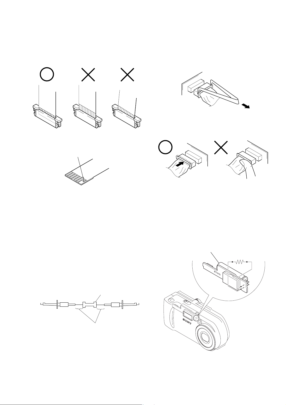
When installing a connector, don’t press down at wire of connector.
It is possible that a wire is snapped.
DSC-P71/P71M
SERVICE NOTE
Make sure that the flat cable and flexible board are not cracked of
bent at the terminal.
Do not insert the cable insufficiently nor crookedly.
Cut and remove the part of gilt
which comes off at the point.
(Be careful or some
pieces of gilt may be left inside)
When remove a connector, don’t pull at wire of connector.
It is possible that a wire is snapped.
[Discharging of the ST-075 board’s charging capacitor
(C510)]
The charging capacitor (C510) of the ST-075 board is charged up
to the maximum 300 V potential.
There is a danger of electric shock by this high voltage when the
battery is handled by hand. The electric shock is caused by the
charged voltage which is kept without discharging when the main
power of the unit is simply turned off. Therefore, the remaining
voltage must be discharged as described below.
Preparing the Short Jig
To preparing the short jig, a small clip is attached to each end of a
resistor of 1 kΩ /1 W (1-215-869-11).
Wrap insulating tape fully around the leads of the resistor to prevent electrical shock.
1 kΩ/1 W
Wrap insulating tape.
Discharging the Capacitor
Short-circuit between the positive and the negative terminals of
charged capacitor with the short jig about 10 seconds.
Capacitor
R:1 kΩ/1 W
(Part code:
1-215-869-11)
– 5 –
Page 6
DSC-P71/P71M
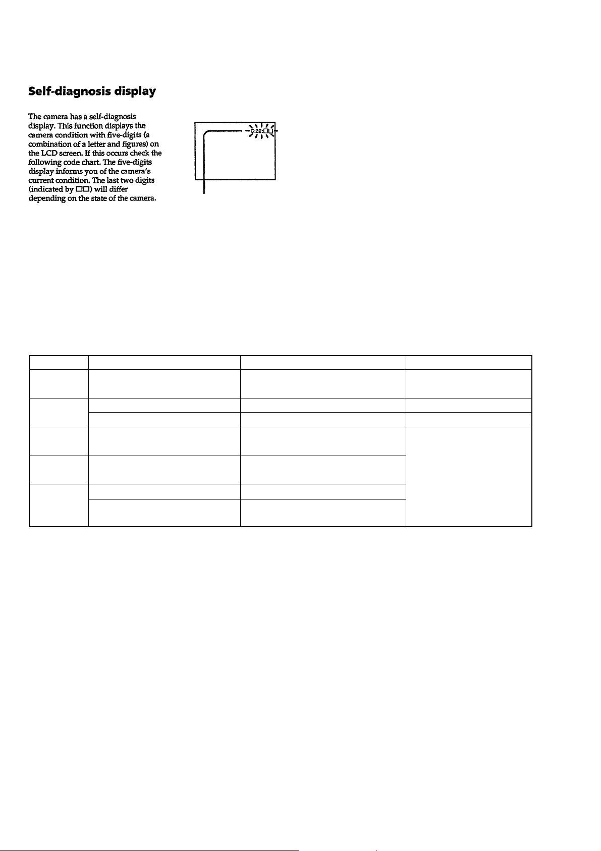
[Description on Self-diagnosis Display]
Self-diagnosis display
• C: ss: ss
You can reverse the camera malfunction yourself. (However , contact your Sony dealer or local
authorized Sony service facility
when you cannot recover from
the camera malfunction.)
• E: ss: ss
Contact your Sony dealer or local authorized Sony service facility.
Display Code
C:32:ss
C:13:ss
E:61:ss
E:91:ss
E:92:ss
Countermeasure
Turn the power off and on again.
Format the “Memory stick”.
Insert a new “Memory Stick”.
Checking of lens drive circuit.
Checking of flash unit or replacement
of flash unit.
Insert a battery pack correctly. Battery pack is not inserted correctly.
Turn the power off and on again.
Trouble with hardware.
Unformatted memory stick is inserted.
Memory stick is broken.
When failed in the focus and zoom
initialization.
Abnormality when flash is being
charged.
Battery pack was installed or removed
when using the AC adaptor.
Cause
Caution Display During Error
SYSTEM ERROR
FORMAT ERROR
MEMORY STICK ERROR
—
– 6 –
Page 7
SECTION 1
GENERAL
DSC-P71/P71M
This section is extracted from
DSC-P31/P71 instruction manual.
WARNING
To prevent fire or shock hazard, do
not expose the unit to rain or
moisture.
For the Customers in the U.S.A.
This symbol is intended to
alert the user to the presence
of uninsulated “dangerous
voltage” within the product’s
enclosure that may be of
sufficient magnitude to
constitute a risk of electric
shock to persons.
This symbol is intended to
alert the user to the presence
of important operating and
maintenance (servicing)
instructions in th e lite ra ture
accompanying the appliance.
If you have any questions about this product,
you may call:
Sony Customer Information Services Center
1-800-222-SONY (7669)
The number below is for the FCC related
matters only.
Declaration of Conformity
Trade Name: SONY
Model No.: DSC-P31
Responsible Party:Sony Electronics Inc.
Address: 680 Kinderkamack
Road, Oradell, NJ
07649 USA
Telephone No.: 201-930-6972
This device complies with Part 15 of the
FCC Rules. Operation is subject to the
following two conditions: (1) This device
may not cause harmful interference, and
(2)this device must accept any interference
received, including interference that may
cause undesired operation.
Declaration of Conformity
Trade Name: SONY
Model No.: DSC-P71
Responsible Party:Sony Electronics Inc.
Address: 680 Kinderkamack
Road, Oradell, NJ
07649 USA
Telephone No.: 201-930-6972
This device complies with Part 15 of the
FCC Rules. Operation is subject to the
following two conditions: (1) This device
may not cause harmful interference, and
(2)this device must accept any interference
received, including interference that may
cause undesired operation.
CAUTION
You are cautioned that any changes or
modifications not expressly approved in this
manual could void your authority to operate
this equipm en t.
2
Note:
This equipment has been tested and found to
comply with the lim its fo r a C la ss B d ig ital
device, pursuant to Part 15 of the FCC Rules.
These limits are designed to provide
reasonable protection against harmful
interferenc e in a r es id en tia l in sta llatio n . T h is
equipment generates, uses, and can radiate
radio frequency energy and, if not installed
and used in accordance with the instructions,
may cause harmful interference to radio
communications. Howev er , there is no
guarantee that interference will not occur in a
particular installation. If this equipment does
cause harmful interference to ra dio or
television reception, which can be determined
by turning the equipment off and on, the user
is encouraged to try to correct the interference
by one or more of the following measures:
—Reorient or relocate the receiving antenna.
—Increase the separation between the
equipment and receiver.
—Connect the equipment into an outlet on a
circuit different from that to which the
receiver is connected.
—Consult the dealer or an experienced
radio/TV technician for help.
The supplied interface cable must be used
with the equipment in order to comply with
the limits fo r a digital device pursuant to
Subpart B of Part 15 of FCC Rules.
For the Customers in the U.S.A.
and Canada
RECYCLING NICKEL-METAL
HYDRIDE BATTERIES
Nickel-metal hydride batteries
are recyclable.
You can help preserve our
environment by returning your
used rechargeable batteries to the
collection and recycling location nearest you.
For more information regardin g rec y clin g o f
rechargeable batteries, call toll free
1-800-822-8837, or
visit http://www .rbrc.org/.
CAUTION
TO PREVENT ELECTRIC SHOCK, DO NOT
USE THIS POLARIZED AC PLUG WITH AN
EXTENSION CORD, RECEPT ACLE OR
OTHER OUTLET UNLESS THE BLADES
CAN BE FULLY INSERTED TO PREVENT
BLADE EXPOSURE.
CAUTION:
To reduce the risk of hazards, use only
USA/UL Certified power supply cord set,
cord is Type SPT-2 or heavier, minimum
NO.18 AWG copper, one end is provided
with a moulded-on male attachment plug
cap (with a specified NEMA
configuration), and the other end is
provided with a moulded-on female
connector body (with a specified IEC nonindustrial type configuration).
NOTICE FOR THE
CUSTOMERS IN THE UNITED
KINGDOM
A moulded plug complying with BS 1363 is
fitted to this equipment for your safety and
convenience.
Should the fuse in the plug supplied need to be
replaced, a 5 AMP fuse approved by ASTA or
BSI to BS 1362, (i.e. marked with or
mark) must be used.
If the plug supplied with this equipment has a
detachable fuse cover, be sure to attach the
fuse cover after you change the fuse. Never
use the plug without the fuse cover . If you
should lose the fuse cover, please contact your
nearest Sony service station.
For the Customers in Germany
Directive:EMC Directive 89/336/EEC,
92/31/EEC
This equipment complies with the EM C
regulations when used under the following
circumstances:
•Residential area
•Business district
•Light-industry district
(This equipment complies with the E MC
standard regulations EN55022 Class B.)
1-1
3
Page 8

DSC-P71/P71M
Attention for the Customers in
Europe
This product has been tested and found
compliant with the limits sets out on the EMC
Directive for using connection cables shorter
than 3 mete rs.
Attention
The electromagnetic fields at the specific
frequencies may influence the picture and
sound of this camera.
“Memory Stick”
For the Customers in the U.S.A.
and Canada
THIS CLASS B DIGIT A L DEVICE
COMPLIES WITH PART 15 OF THE FCC
RULES AND THE CANAD IAN ICES-003
OPERA TION IS SUBJECT TO THE
FOLLOWING TWO CONDITIONS:
(1) THIS DEVICE MA Y NOT CAUSE
HARMFUL INTERFERENCE, AND
(2)THIS DEVICE MUST ACCEPT ANY
INTERFERENCE RECEIVED,
INCLU DING INT ERFE REN CE T HAT MAY
CAUSE UNDESIRED OPERATION.
4
N50
Before using your camera
Trial recording
Before you record one-time events, you may
want to make a trial recording to make sure
that the cam era is working correctly .
No compensation for contents of the
recording
Contents of the recording cannot be
compensated for if recording or playback is
not possible due to a malfunction of your
camera or recording medium, etc.
Notes on image data compatibility
•This camera conforms with the Design Rules
for Camera File Systems universal standard
established by the JEITA (Japan Electronics
and Information Technology Industries
Association).
•Playback of images recorded with your
camera on other equipment and playback of
images recorded or edited with other
equipment on your camera are not
guaranteed.
Precaution on copyright
Television programs, films, video tapes, and
other materials may be copyrighted.
Unauthorized recording of such materials may
be contrary to the provision of the copyright
laws.
1-2
5
Page 9

DSC-P71/P71M
Do not shake or strike the camera
In addition to malfunctions and inability to
record images, this may render the “Memory
Stick” unusable or image data breakdown,
damage or loss may occur.
LCD screen, LCD finder (only models
with a finder) and lens
•The LCD screen and the LCD finder are
manufactured using extremely highprecision technology so over 99.99% of the
pixels are operational for effective use.
However, there may be some tiny black
points and/or bright points (white, red, blue
or green in color) that constantly appear on
the LCD screen and the LCD f inder. These
points are normal in the manufacturing
process and do not affect the recording in
any way.
•Be careful when placing the camera near a
window or outdoors. Exposing the LCD
screen, the finder or the lens to direct
sunlight for long periods may cause
malfunctions.
Do not get the camera wet
When taking pictures outdoors in the rain or
under similar conditions, be careful not to get
the camera wet. If moisture condensation
occurs, see page 99 and follow the
instructions on ho w to remo v e it before using
the camera.
6
The auto zoom lens (for the DSC-P71
only)
This camera is equipped with an auto zoom lens.
Be careful not to bump the lens, and be careful
not to apply force to it.
On illustrations
Illustrations used in this manual are of the DSCP71 unless noted otherwise.
The pictures used in this manual
The photographs used as examples of pictures in
this manual are reproduced images, and are not
actual images shot using this camera.
Trademarks
• “Memory Stick,” , “MagicGate Memory
Stick,” and , are trademarks of Sony
Corporation.
• is a trademark of Sony
Corporation.
• Microsoft and Windows are registered
trademarks of the U.S. Microsoft Corporation
in the United States and other countries.
• Macintosh, Mac OS, and QuickTime, are
trademarks or registered trademarks of Apple
Computer, Inc.
• In addition, system and product names used in
this manual are, in general, trademarks or
registered trademarks of their respective
developers or manufacturers. However, the
or ® marks not used in all cases in this manual.
™
1-3
7
Page 10
DSC-P71/P71M
1
q
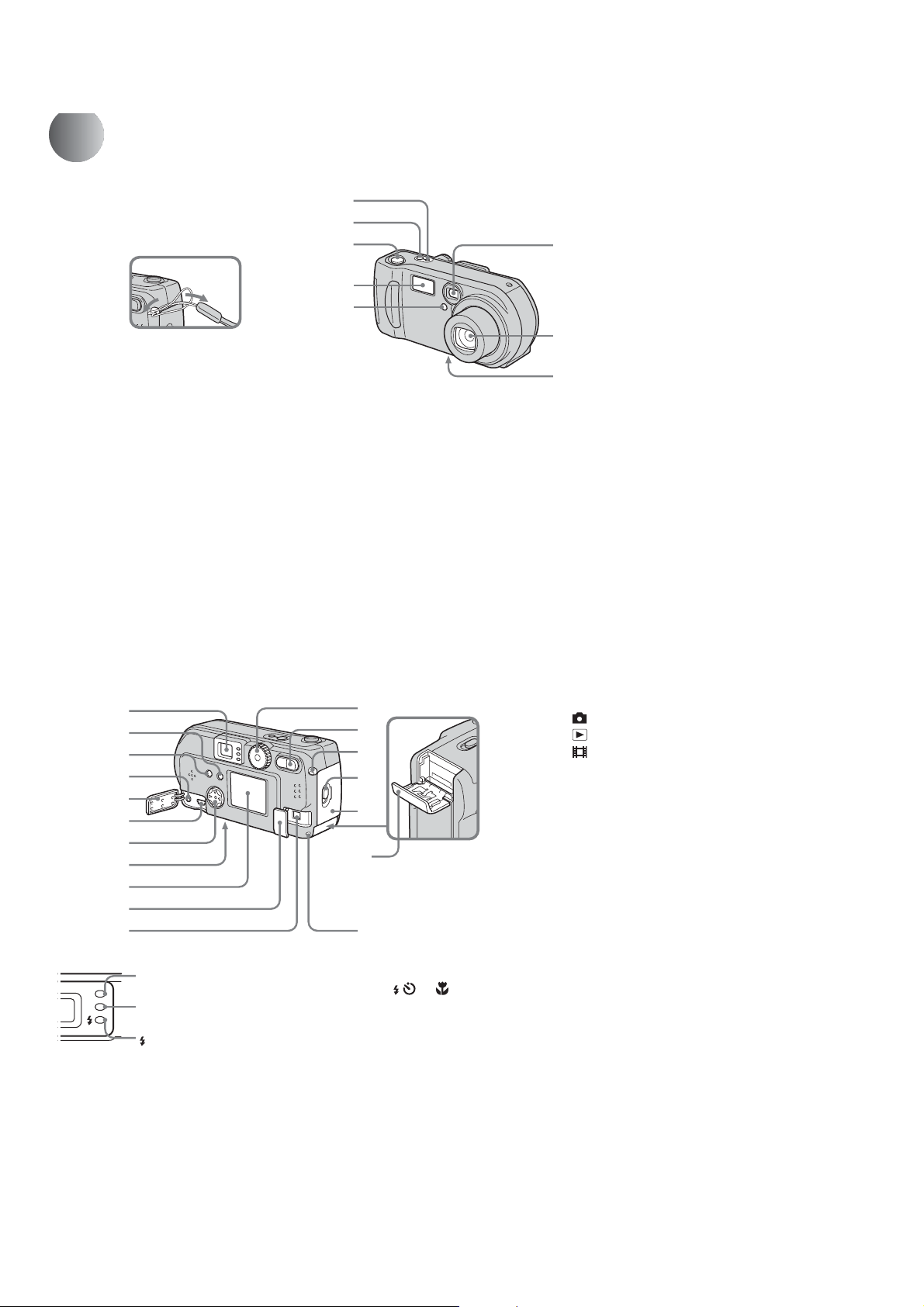
Identifying the parts (DSC-P71)
Attaching
the strap
2
3
4
5
6
7
8
A POWER ON/OFF lamp (20)
B POWER button (20)
C Shutter button (26)
D Flash (30)
E Self-timer lamp (29)/
AF illuminator (31, 97)
F Finder window
G Lens
H Tripod receptacle (bottom
surface)
10
1
2
3
4
5
6
7
8
9
q;
qa
A Finder
Self-timer/recording
lamp (red)
AE/AF lock lamp
(green)
Flash charge lamp
(orange) (30)
B DISPLAY/LCD ON/OFF button
(32)
C MENU button (24)
D VIDEO OUT jack (38)
E Jack cover
F USB jack (47)
• Use a tripod with a screw length of less than
5.5mm (7/32 inch). You will be unable to
firmly secure the camera to tripods having
longer screws, and may damage the camera.
s
qd
qf
qg
qh
qj
qk
G Control button
(Menu on) (v/V/b/B/z) (20)/
(Menu off) ( / /7/) (27, 29, 30)
H RESET button (bottom surface)
(82)
I LCD screen
J DC IN jack cover (19)
K DC IN jack (19)
L Mode dial (21)
: To shoot still images
: To view or edit images
: To shoot mo vies /Clip Motion
images/Multi Burst mode images
SET UP: To set the SET UP items
SCN: To shoot in the SCENE
SELECTION mode
M Zoom button (for shooting) (28)/
Index button (for viewing) (37)
N Wrist strap hook
O Open lever
P Battery cover
Q “Memory Stick” cover
R Access lamp (23)
1-4
11
Page 11
DSC-P71/P71M
Getti
d
ng starte
Preparing batteries
Use the following batteries in this camera.
Acceptable batteries
R6 (size AA) Nickel-Metal Hydride
batteries (2)
– NH-AA-DI (2) (supplied)
– NH-AA-2DI twin-pack (recommended, not
supplied)
Batteries that cannot be used
Manganese batteries, lithium batteries, nicad batteries, alkaline batteries (cannot be
used with the DSC-P71)
* Use of AA alkaline batteries may result in
shorter than desired operating time. (only in the
DSC-P31)
When alkaline batteries are used, take note of
the following information.
• Turn POWER SAVE “ON”, shut the LCD
screen off, and use the Finder to shoot your
images. This will lengthen battery life
(page 16).
• There is a big difference in the performance
of batteries of different types and of batteries
made by different manufacturers. This is
especially true in low temperatures, where
some batteries are noticeably weaker.
You may not be able to shoot in temperatures
below +5°C (41°F).
• The battery remaining indicator may not
display the correct information.
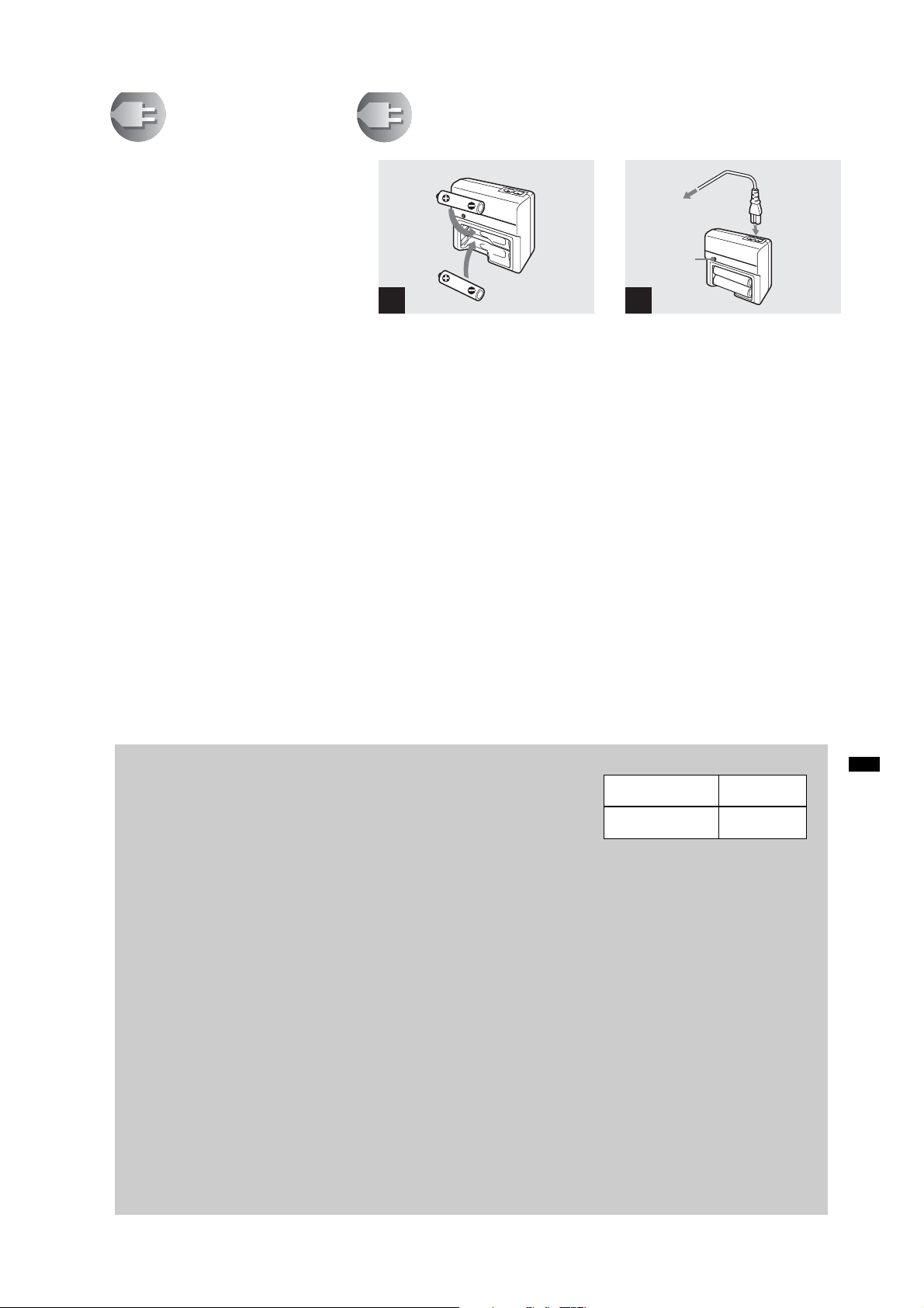
Charging the batteries
BC-CS1 (supplied)
Insert with the cor-
1
,
Insert Nickel-Metal Hydride
batteries into the charger
(supplied).
• Be sure to charge the Nickel-Metal Hydride
batteries supplied with your camera before
using them.
• Be sure to charge the batteries in an
environment where the ambient temperature is
10°C to 30°C (50°F to 86°F). If the batteries are
charged in an environment where the
temperature is outside that range, the batteries
may not charge efficiently.
• Connect the battery charger to an easily
accessible wall outlet (mains) close by. If
something goes wrong while you are using the
charger, immediately shut off the power by
pulling the plug out of the wall outlet.
rect polarity +/−
To the wall outlet
(mains)
Charge
lamp
Power cord
(mains lead)
2
, Connect the charger to a wall
outlet (mains) using the power
cord (mains lead).
Charging starts, and the charge lamp lights.
When the charge lamp goes out, charging is
finished.
• When charging is finished, disconnect the
power cord (mains lead) from the wall outlet
(mains), and remove the Nickel-Metal Hydride
batteries from the charger.
• When transporting the Nickel-Metal Hydride
batteries, be sure to use the battery case
(supplied). If the +/− metal terminals are
shorted, there is a possibility of danger from
excessive heat or fire.
14
Charging the Nickel-Metal
Hydride batteries
• If the poles of the Nickel-Metal Hydride
batteries are dirty, the batteries may not
charge properly. Occasionally clean the poles
of the batteries and the terminals of the
charger by wiping them with a dry cloth.
• At the time of purchase, or when the Nickel-
Metal Hydride batteries haven’t been used for
a long time, they may not fully charge. This is
typical of this type of battery, and is not a
malfunction. If this happens, repeatedly using
up the battery fully, and then recharging it,
should correct the problem.
• Even when Nickel-Metal Hydride batteries
are not being used they loose their charge
naturally over time. It is recommended that
you recharge the batteries just before using
them.
• If you recharge Nickel-Metal Hydride
batteries before fully using up the existing
charge, the so-called memory effect* can
occur, and the low battery warning will be
triggered sooner than expected. Charging the
battery after fully depleting the existing
charge should correct the problem.
* The “memory effect” – the situation in
which a battery temporarily accepts a less
than full charge.
•To use up the batteries completely, put
the camera in “SLIDE SHOW” mode
and leave it that way until the batteries
are used up (page 67).
Precautions to be observed
when charging the batteries
• Do not charge any other batteries except Son y
Nickel-Metal Hydride batteries in the charger
supplied with your camera. If you try to
charge any other type of battery (e.g.,
manganese batteries, alkaline dry cells, or
one-time lithium batteries) than the batteries
specified, those batteries may leak, overheat,
or explode, causing the danger of burns or
other injuries.
• Be sure to charge both Nickel-Metal Hydride
batteries at the same time.
• When the batteries are charged, use them only
in an environment where the temperature
range is 0°C to 40°C (32°F to 104°F).
Otherwise, there is a danger of leaks,
explosions, excessive heat, fire, or electric
shock.
• Do not charge fully charged Nickel Metal
Hydride batteries again. Otherwise, there is a
danger of leaks, explosions, excessive heat,
fire, or electric shock.
• Do not peel off the external seals or damage
the batteries. Never use batteries from which
the seals have been partially or completely
removed, or batteries that have been split in
any way.
Charging time
Nickel-Metal
Charging time
Hydride battery
NH-AA-DI × 2
(supplied)
Approx. 13
hours
This represents the time required to charge
fully depleted Nickel-Metal Hydride
batteries using the supplied BC-CS1
charger in an environment where the
ambient temperature is 25°C (77°F).
• Charging is complete in approximately 13
hours. The charge lamp may remain lit longer
than 13 hours, but this is not a malfunction.
• If you use the ACC-CSNQ STAMINA “Super
Quick charge” kit (not supplied), the batteries
will charge faster.
Getting started
15
1-5
Page 12
DSC-P71/P71M
Charging the Nickel-Metal hydride batteries (continued)
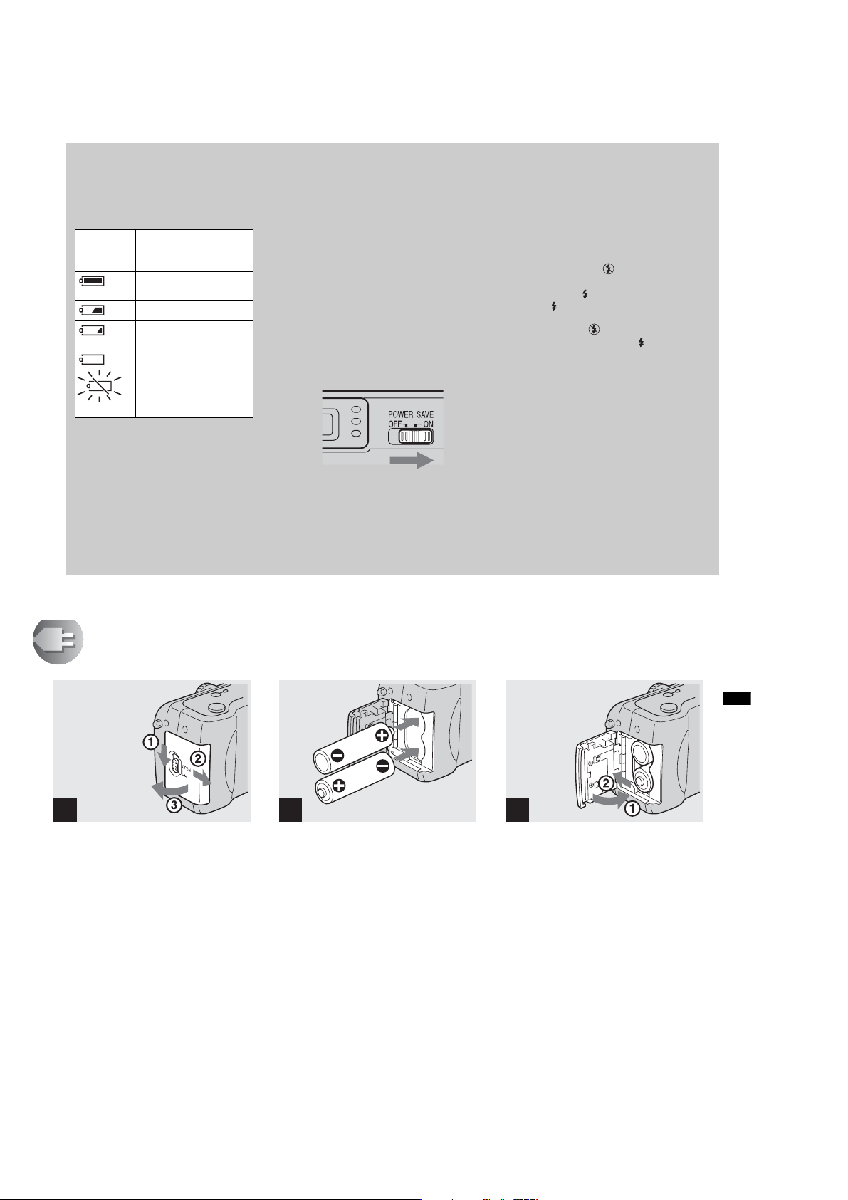
Battery remaining indicator
As the battery power decreases with use,
the Battery remaining indicator displays
the amount of power remaining using the
following symbols.
Battery
remaining
indicator
Flashing
• If the LCD screen is off, press the DISPLAY/
LCD ON/OFF button to turn it on.
• Based on the conditions under which the
camera is being used and the state of the
charge, or on the environment, this
information may not be correctly indicated.
• When the AC adaptor is being used, the
Remaining battery information is not
displayed.
Battery remain in g
guidelines
(A full charge is 100%)
Sufficient power
remaining
Battery half full
Battery low, recording/
playback will stop soon.
Change the batteries for
fully charged ones, or
charge these batteries.
The POWER SAVE function
When the POWER SAVE function is set
to ON, you can shoot for a longer period of
time.
DSC-P71
Turn the Mode dial to SET UP, and set
“POWER SAVE” in “SETUP 2” to “ON”.
When the camera is shipped from the
factory, this item is set to “ON” (page 98).
DSC-P31
Set the POWER SAVE switch to ON.
When the camera is shipped from the
factory, this switch is set to ON.
When the POWER SAVE function is
ON
• The LCD screen will be darker than it is when
POWER SAVE is set to OFF. You cannot
change the settings for “LCD BACKLIGHT”
at this time (page 98). To make the available
shooting time even longer, it is recommended
that you turn off the LCD screen and use the
Finder to do your shooting (page 32).
• In Flash mode, the “ ” (No flash) is
displayed. If you want to shoot using the
flash, press v ( ) on the control button, and
select “ ” (forced flash) or Auto (page 30).
• When the power turns on, the Flash mode is
normally set to “ ” (No flash).
• When the flash is charging (“ ” the Flash
charge lamp blinks), the LCD screen turns
off.
• In shooting still images, the focus only
focuses when the shutter is pushed down
halfway.
16
Inserting the batteries
1 2 3
, Open the Battery cover.
Slide it in the direction of the arrow, and it
opens out.
, Insert the batteries .
Match the
marks inside the battery case.
−
• Occasionally clean the poles of the batteries
and the terminals of the Battery cover by
wiping them with a dry cloth. If the poles of the
batteries or the terminals become covered with
a film of dirt or oil from the skin, the operating
time of the camera can be greatly reduced.
poles of the batteries to the
+/−
+
, Close the Battery cover.
Close the Battery cover while holding the
/
batteries in. Make sure the cover is closed
securely.
To remove the batteries
Stand the camera on end, open the Battery
cover upward, then remove the batteries.
• Make sure you don’t drop the batteries when
opening or closing the Battery cover.
Getting started
1-6
17
Page 13
Inserting the batteries (continued)
(
)
)
DSC-P71/P71M
Battery life and the number of
images that can be recorded/
played back
The tables show approximate guidelines
for the length of time the camera can be
used when picture quality is set to
Standard, when you shoot in Flash mode
“”, and when you shoot in Normal
mode in an environment where the
ambient temperature is 25°C (77°F), and
the supplied Nickel-Metal Hydride
batteries are fully charged. The guidelines
for the number of images that can be
recorded or played back allow for
changing the “Memory Stick” as
necessary. Actual results may differ
slightly from these, depending on the
conditions of use.
When shooting* still images
DSC-P71
Imag e
size
2048×1536
640×480
R6 (size AA) Ni-MH (2) (supplied)
LCD
Battery
life (min .)
screen
ON Approx. 90 Approx. 1800
OFF Approx. 120 Approx. 2400
ON Approx. 90 Approx. 1800
OFF Approx. 120 Approx. 2400
No. of
imag es
DSC-P31
R6 (size AA) Ni-MH (2) (supplied)
Imag e
size
1600×1200
640×480
* Recording one image every three seconds
When playing back** still images
DSC-P71
Imag e size
2048×1536 Approx. 230 Approx. 4600
640×480 Approx. 230 Approx. 4600
DSC-P31
Imag e size
1600×1200 Approx. 280 Approx. 5600
640×480 Approx. 280 Approx. 5600
LCD
Battery
life (min.)
screen
ON Approx. 120 Approx. 2400
OFF Approx. 150 Approx. 3000
ON Approx. 120 Approx. 2400
OFF Approx. 150 Approx. 3000
R6 (size AA) Ni-MH (2 )
(supplied)
Battery life
(min.)
R6 (size AA) Ni-MH (2 )
(supplied)
Battery life
(min.)
No. of
images
No. of images
No. of images
**With the LCD screen on, showing single
images in order, one approximately every
three seconds
Recording*** movies images
R6 (size AA) Ni-MH (2 )
(supplied)
LCD screen
ON (min.)
DSC-P71 Approx. 120 Approx. 170
DSC-P31 Approx. 150 Approx. 200
*** Continuous recording with a picture size of
160×112
LCD screen
OFF(min.)
18
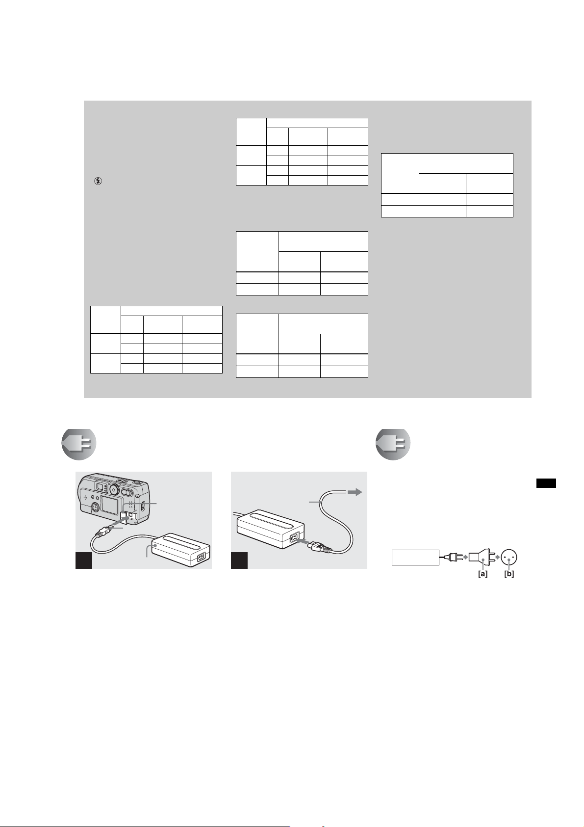
Using an external power source
DC IN jack
cover
DC plug
AC power adaptor
1
not supplied
, Open the DC IN jack cover,
then connect the AC-LS1 AC
power adaptor (not supplied)
to the DC IN jack of the c amera .
Connect the cable with the v mark facing
up.
• Connect the AC power adaptor to an easily
accessible wall outlet (mains) close by. If
something goes wrong while you are using the
adaptor, immediately shut off the power by
pulling the plug out of the wall outlet.
2
, Connect the power cord (mains
• When you have finished using the AC power
adaptor, disconnect it from the DC IN jack of
the camera.
• To use power from an automobile, use a DC
adaptor/Charger (not supplied).
• If you insert or remove the DC plug while you
are using the batteries, the power may shut off.
Power cord
(mains lead)
lead) to the AC power adaptor
and to the wall ou tle t (mains).
2 To the wall outlet (mains
1
Using your camera
abroad
Power sources
You can use your camera in any country or
area with the supplied battery charger
within 100 V to 240 V AC, 50/60 Hz. Use a
commercially available AC plug adaptor
[a], if necessary, depending on the design of
the wall outlet (wall socket) [b].
BC-CS1
Getting started
19
1-7
Page 14
DSC-P71/P71M
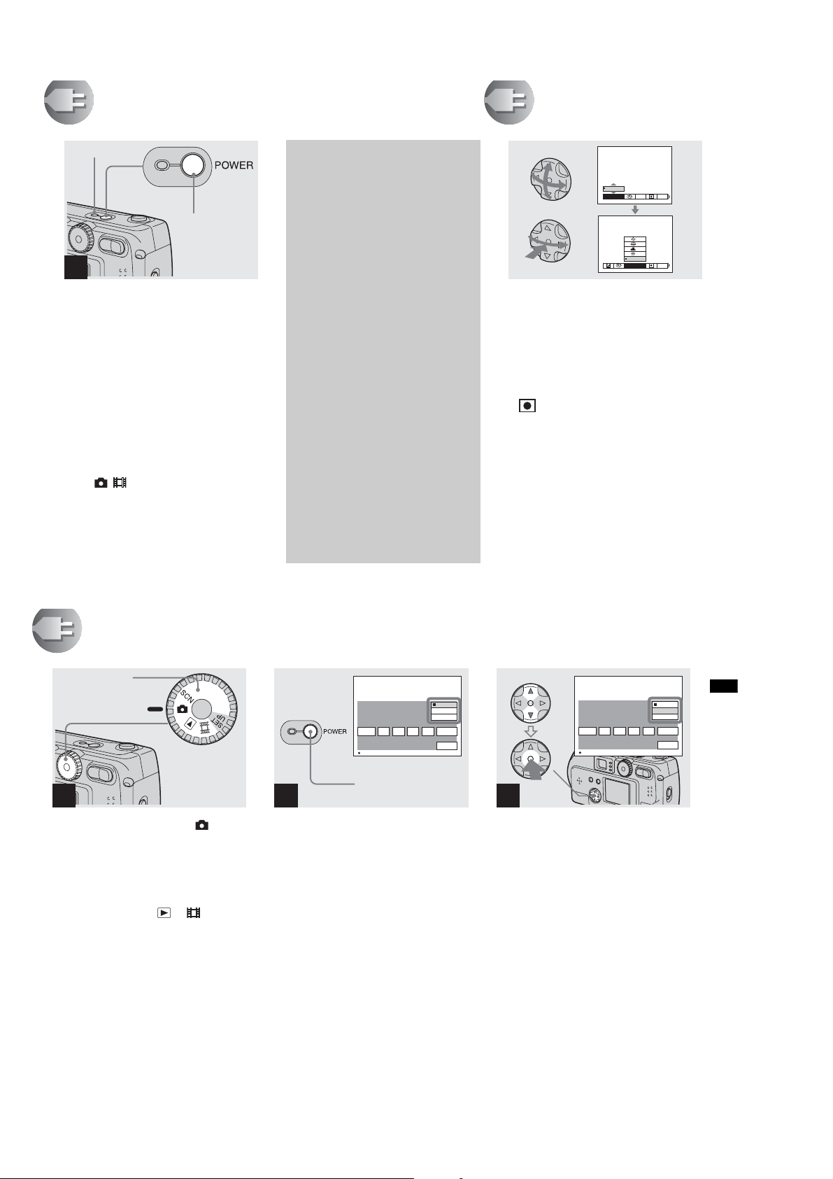
Turning on/off your camera
POWER ON/
OFF lamp
POWER button
1
, Press the POWER button.
The POWER ON/OFF lamp lights in green,
the power is on, and the lens cover opens.
When you turn on your camera for the first
time, the “CLOCK SET” screen appears
(see the next page).
To turn off the power
If you press the POWER button again, the
POWER ON/OFF lamp goes out, and the
camera turns off.
• if you turn the power on when the Mode dial is
set to , , or SCN, the lens begins to move
(DSC-P71 only). Please be careful not to touch
the lens.
The Auto Power Off feature
If no tasks are performed for a while*
when shooting, playing back, or
performing SET UP while using the
batteries, power is automatically shut
off to preserve battery power.
However, in the following
circumstances, even if the battery is
being used to power the camera, the
Auto Power Off feature will not work.
•Movies are being played back
•A slide show is being shown
•There is a plug in the USB terminal
or the VIDEO OUT jack
* When POWER SAVE is set to ON:
approximately 90 seconds
When POWER SAVE is set to OFF:
approximately 3 minutes
How to use the
control button
0EV
0EV
WB
EV
To change the current settings of the
camera, bring up the menu or SET UP on
the LCD screen (page 55), and use the
control button to make the changes.
For each item, press v/V/b/B to select the
desired value, then press the center z or
b/B to make the setting.
• (Spot light-metering) is not displayed on
the menu of the DSC-P31 (page 61).
AUTO
WHITE BAL
ISO
ISO
20
Setting the date and time
Mode dial
1
, Turn the Mode dial to .
• To change values for the time and the date that
have been previously set, change the Mode dial
to SET UP, choose “CLOCK SET” in “SETUP
1” (page 97), then proceed from Step 3.
• You can also carry out this operation when the
mode dial is set to SCN, , or .
12 02
Y/M/D
M/D/Y
D/M/Y
AM
CANCEL
OK
CLOCK SET
2002
1
/:
/
1
OK
POWER button
2
, Press the POWER button.
The POWER lamp lights in green and the
“CLOCK SET” screen appears.
CLOCK SET
2002
/:
/
1
OK
Y/M/D
M/D/Y
D/M/Y
12 02
AM
CANCEL
OK
1
3
, Choose the desired order for
the date, the month and the
year using v/V on the control
button, then push the center z.
You can choose from “Y/M/D” (year/
month/day), “M/D/Y”, and “D/M/Y”.
• If the rechargeable button battery, which
provides the power for saving the time data,
ever loses its charge (page 99), the “CLOCK
SET” screen automatically reappears. If this
happens, reset the date and time by following
the above procedure, starting from Step 3.
Getting started
1-8
21
Page 15
Setting the date and time (continued)
Shooti
till i
DSC-P71/P71M
CLOCK SET
2002
1
/:
/
1
OK
4
, Choose the year, month, day,
hour, and minute items using
b/B.
A v will be shown above, and a V will be
shown below the item currently selected to
be set.
22
12 02
Y/M/D
M/D/Y
D/M/Y
AM
CANCEL
10 30
Y/M/D
M/D/Y
D/M/Y
PM
CANCEL
OK
CLOCK SET
2002
4
/:
/
7
OK
12 02
Y/M/D
M/D/Y
D/M/Y
AM
CANCEL
OK
6
, Choose “OK” using the B on
the control button, and then
press the center z.
After the date and time are set, the clock
will start to keep time.
• To abort the setting process, choose
“CANCEL”, and press the center z.
CLOCK SET
OK
2002
1
/:
/
7
OK
5
, Set the desired numerical
value using v/V on the control
button, then press the center
z.
After setting the current numerical value,
move to the next item. Repeat the above
process until all of the items have been set.
• If you choose “D/M/Y” in Step 3, use the 24
hour clock display.
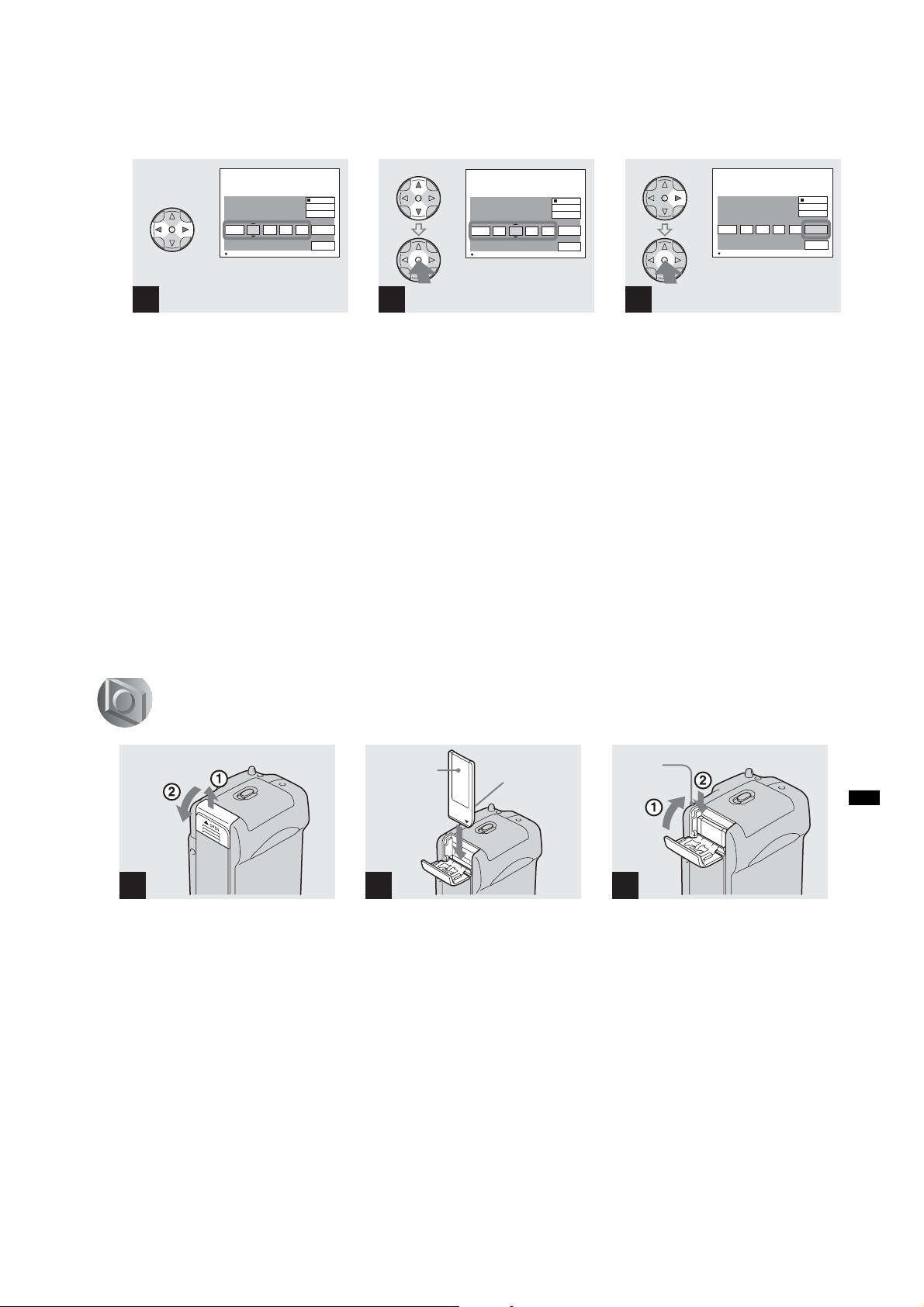
Inserting and removing a “Memory Stick”
Bottom
1
, Open the “Memory Stick”
cover.
Slide the cover in the direction of the arrow
to open it.
Label side
2
, Insert the “Mem ory Stick.”
Holding the “Memory Stick” as shown in
the illustration, insert it all the way in until
it clicks.
• Whenever you insert a “Memory Stick,” push it
all the way in until it clicks. If you do not insert
it correctly, a message such as “MEMORY
STICK ERROR” will be displayed on the LCD
screen.
Connector
side
Access
lamp
ng s
mages
3
, Close the ”Memory Stick”
cover.
To remove a “Memory Stick”
Open the “Memory Stick” cover, then push
the “Memory Stick” to pop it out.
•Whenever the Access lamp is lit, the
camera is recording or reading out an
image. Never remove the “Memory
Stick” or turn off the power at this time.
Shooting still images
1-9
23
Page 16
DSC-P71/P71M
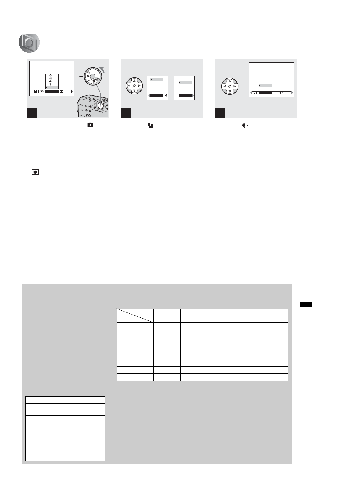
Deciding the still image size and image quality
FINE
AUTO
WHITE BAL
Menu button
ISO
1
, Turn the Mode dial to , turn
on the power, and then push
the MENU button.
The menu appears.
• You can also carry out this operation when the
mode dial is set to SCN.
• (Spot light-metering) is not displayed on
the menu of the DSC-P31 (page 61).
24
2048x1536
2048 (3 : 2)
1600x1200
1280 x 960
640 x 480
IMAGESIZE
SO
1600x1200
1600 (3 : 2)
1280 x 960
640 x 480
IMAGE SIZE
DSC-P71 DSC-P31
2
, Select “ ” (Image size) using
b/B on the control button. Use
v/V to sele ct the desired image
size.
The image size is set.
FINE
STANDARD
P.QUALITY
MODE
PFX
3
, Select “ ” (Image quality)
using b/B on the control
button. Use v/V to s e lec t th e
desired image quality.
The image quality is set.
When the setting is completed, press the
MENU button. The menu disappears from
the screen.
• For image quality, you can choose either
“FINE” or “ST ANDARD”.
• The image size and quality values chosen here
will be preserved even when the camera is
turned off.
Image size and quality
You can choose image size (number of
pixels) and image quality (compression
ratio) based on the kind of images you
want to shoot. The larger you make the
image size and the higher you make the
image quality, the better your image, but
also the larger the amount of data needed
to preserve your image. This means you
can save fewer images in your “Memory
Stick.”
Choose an image size and quality level
appropriate for the kind of images you
want to shoot.
You can resize the images later (Resize
function, see page 71).
You can choose image size from among
the six options in the following tables.
Image size Examples
2048×1536
(DSC-P71 )
2048(3:2)
(DSC-P71 )
1600×1200 Printing A4 size images
1600 (3:2)
(DSC-P31 )
1280×960 Printing postcard size images
640×480
Very fine prints
3:2 prints
3:2 prints
1)
1)
For images to be attached to e-mail
The number of images* that can be saved in a “Memory Stick”
The number of images that can be saved in FINE (STANDARD) mode are shown below.
(Units: number of images)
Capacity
Image size
2048×1536
(DSC-P 7 1 )
2048(3:2)
(DSC-P71)
1600×1200 8 (15) 16 (30) 32 (60) 64 (120) 128 (240)
1600 (3:2)
(DSC-P 3 1 )
1280×960 12 (22) 24 (44) 50 (93) 100 (186) 200 (372)
640×480 48 (118) 96 (240) 195 (488) 393 (983) 786 (1966)
* When the shooting mode is normal
For the number of images that can be saved in
other modes, see page 91.
• The image size is the screen size used when
viewing the images on a personal computer.
When the images are viewed on the LCD
screen of the camera, they all look the same
size.
• Number of shooting images can differ from
these values according to shooting conditions.
1)
This option records images in a horizontal to
vertical proportion of 3:2 to match the size of
the print paper used.
8MB 16MB 32MB 64MB 128MB
5 (9) 10 (18) 20 (36) 40 (72) 80 (144)
5 (9) 10 (18) 20 (36) 40 (72) 80 (144)
8 (15) 16 (30) 32 (60) 64 (120) 128 (240)
• The image size value (e.g., 2048×1536) is the
number of pixels displayed.
For information how to shoot images to be
used as attachments to e-mail messages,
see page 65.
Shooting still images
25
1-10
Page 17
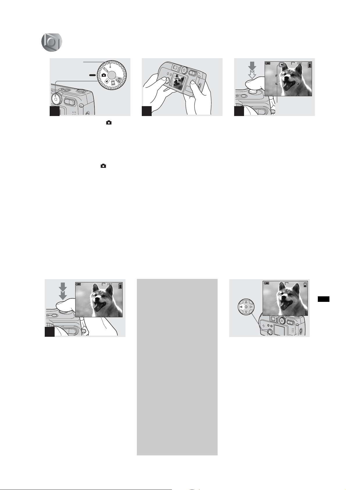
Basic still image shooting (using auto adjustment mode)
DSC-P71/P71M
Mode dial
1
, Set the mode dial to , and
turn on your camera.
• The lens cover opens when the power is turned
on.
• When the camera is turned on or when using
the zoom, and the lens is moving, don’t touch
the lens assembly (DSC-P71 only) (page 28).
• When the Mode dial is set to , the exposure
and focus are adjusted automatically.
• Clean the lens with a soft cloth if it is dirty
(page 99).
2
, Hold your camera with your
both hands and position a
subject in the center of the
frame to fo c u s on .
Do not cover the lens or flash with your
fingers.
• You can choose either Multi-point AF mode or
Center AF as the AF mode (page 58).
2048
4
F2.1
50
Flashes in
3
green t Lights up
, Press and hold the shutter
halfway down.
The camera beeps. When the AE/AF lock
indicator stops flashing and remains on, the
camera is ready for shooting.
• If you remove your finger from the shutter,
shooting will be canceled.
• The minimum focal distance to a subject is 50
11
/16 inches) for the DSC-P71, and 10
cm (19
15
/16 inches) for the DSC-P31. To shoot
cm (3
subjects at distances closer than this, use Macro
mode (DSC-P71 only) (page 28).
• The frame appearing on the LCD screen shows
the limits of the area where the focus will be
adjusted. (For more details on the AF range
finder, see page 58.)
26
2048
4
, Press the shutter fully down.
A beeping sound is heard, the shooting is
completed, and the still image is saved in
the “Memory Stick.” When the Recording
lamp goes out, you can shoot the next
image.
• When you are shooting with the battery, if no
tasks are performed for a while* with the
camera turned on, power is automatically shut
off to preserve battery power (page20).
* When POWER SAVE is set to ON:
approximately 90 seconds
When POWER SAVE is set to OFF:
approximately 3 minutes
About Auto Focus
When you try to shoot a subject that is
hard to focus on, the AE/AF lock
indicator will change to flashing
slowly.
The Auto Focus function may be
difficult to use with in the following
subjects. In such cases, release the
shutter, then try to recompose the shot
and focus again.
• The subject is distant from the camera and
dark
• The contrast of the subject and its
background is poor
• The subject is seen through glass, such as
a window
• A fast-moving subject
• The subject has a reflection, such as that
from a mirror, or there is a luminous body
and a lustrous subject
• A flashing subject.
Checking the last shot
image (Quick Review)
2048
10:30
6/8
PM
REVIEW
2002 7 4100-0029
, Press b (7) on the control
button.
To return to shooting mode, press the
shutter lightly or press b (7) on the control
button again.
To delete the image displayed on the
LCD screen
1 Press MENU button to display the menu.
2 Press B on the control button to select
“DELETE”, then press the center z.
3 Press v on the control button to select
“OK”, then press the center z.
The image will be deleted.
Shooting still images
1-11
27
Page 18
DSC-P71/P71M
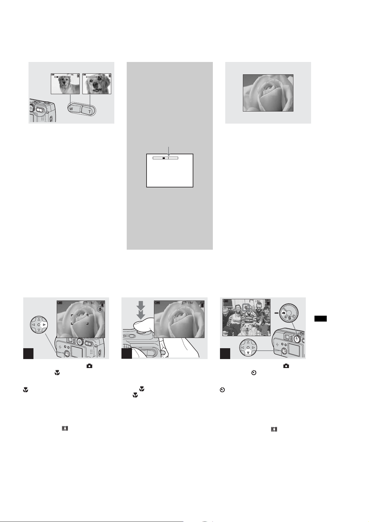
Using the zoom feature
W (wide-angle) T (telephoto)
2048
4
T
W
W
, Press the Zoom button to
choose the desired image size,
and shoot your image.
The minimum distance needed
to focus on a subject
DSC-P71
50 cm (19
angle) and T (telephoto)
DSC-P31
10 cm (3
• The lens moves when the zoom feature is being
used (DSC-P71 only). Be very careful not to
touch the lens.
• The zoom feature cannot be used when
shooting movies (page 83).
11
/16 inches) for both W (wide
15
/16 inches)
28
Shooting close-ups (Macro)
(DSC-P71 only)
Digital zoom
2048
4
T
DSC-P71
When the zoom exceeds 3x,
enlargement is carried out using digital
processing of the image. The image can
then be enlarged up to 6x using the
digital zoom feature. Because picture
quality deteriorates when digital zoom
is used, set “DIGITAL ZOOM” in SET
UP to “OFF” when this feature is not
needed (page 97).
The T side of this line shows
the extent of digital zoom
W
T
DSC-P31
The DSC-P31 does not have an optical
zoom. It has only a 3x digital zoom.
There is no Digital zoom item in SET
UP.
• When you are using digital zoom, you
cannot confirm the image using the finder.
• When you are using the digital zoom
feature, the Auto focus frame is not
displayed.
For close-ups of small subjects like flowers
or insects, shoot using the Macro feature.
You can use this feature for close-ups of
subjects up to the distances specified below.
When the zoom is set all the way to
the W side: distances up to 10 cm (3
15
/16
inches) from the end of the lens
When the zoom is set all the way to
the T side: distances up to 50 cm (19
11
/16
inches) from the end of the lens
2048
4
1
, Turn the Mode dial to , and
press B () on the control
button.
(Macro) will appear on the LCD screen.
• If the menu is currently displayed, press the
MENU button first and the menu will
disappear.
• You can perform this operation even when the
Mode dial is set to SCN (other than Landscape
mode) (page 34), or .
2048
2
, Center the subject in the frame,
and shoot the image.
To return to normal shooting
Press B () on the control button one more
time. disappears from the LCD screen.
• Use the LCD screen to shoot when using the
Macro feature. If you use the finder, the limits
of what you see and what you actually shoot
may be different.
Using the self-timer
2048
4
1
, Turn the Mode dial to , and
press V () on the control
button.
(Self-timer) will appear on the LCD
screen.
• If the menu is currently displayed, press the
MENU button first and the menu will
disappear.
• You can also carry out this operation when the
mode dial is set to SCN, or .
Shooting still images
1-12
29
Page 19
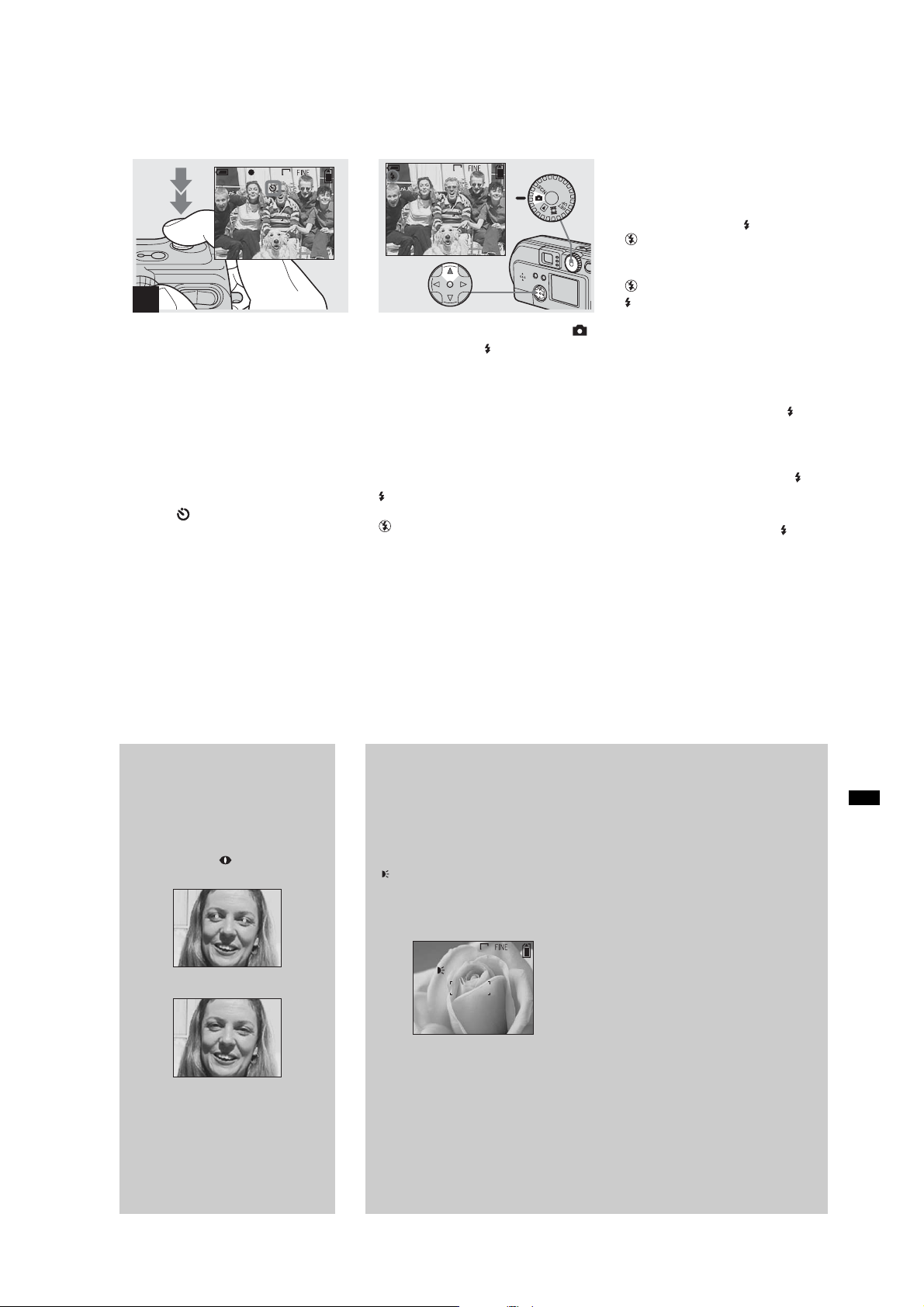
Selecting a flash mode
DSC-P71/P71M
2048
3
0EV
F2.3
50
2
, Center the subject in the frame,
and press the shutter all the
way down.
The Self-timer lamp (page 10 for the DSCP71, page 12 for the DSC-P31) will blink in
orange, and you will hear a beeping sound.
The image will be shot within
approximately 10 seconds.
To cancel the self-timer in the middle
of the operation
Press V () on the control button one more
time.
• If you stand in front of the camera and press the
shutter, the focus and the exposure may not be
correctly set.
2048
4
, Turn the mode dial to select ,
and press v () on the control
button repeatedly to select a
flash mode.
Flash mode has the following features.
No indicator (Auto): Based on the
lighting conditions, the camera will decide
if there is enough light, and will use the
flash accordingly (factory setting).
(forced flash): The flash will be used
regardless of the amount of ambient light.
(no flash): The flash will not be used.
Each time you press the button, the display
changes as follows.
When POWER SAVE is OFF
No indicator (Auto) t (forced flash) t
(no flash)
When POWER SAVE is ON
(no flash) t No indicator (Auto) t
(forced flash)
• If the menu is currently displayed, press the
MENU button first and the menu will
disappear.
• You can change the brightness of the flash
using “FLASH LEVEL” in the settings menu
(page 93).
• When Flash mode is set to Auto or (forced
flash), and you look at the LCD screen in a dark
place, you may notice some “noise” in the
image, but this will have no effect on the image
you shoot.
• While the flash is being charged, the Flash
charging lamp blinks. When charging is
completed, the lamp goes out.
• When you press the shutter button halfway
down while the flash is flashing, ( ) the Flash
charge lamp turns on.
30
To reduce “red-eye” when
recording live subjects
When the flash begins to strobe before
the image is shot, the red-eye
phenomenon is reduced. In SET UP,
set “RED EYE REDUCTION” to
“ON” (page 97). “ ” will be displayed
on the LCD screen.
m
• The amount of red-eye reduction possible
varies according to the individual. In
addition, the distance to the subject, and
whether or not the subject has seen the
flash begin to strobe may also reduce the
effectiveness of the red-eye reduction
process.
Shooting with th e AF
illumina to r
This is additional lighting provided to
assist in focussing when shooting in dark
places.
Set “AF ILLUMINATOR” (page 97) in
SET UP to “AUTO”. When shooting,
“” is displayed; the AF illuminator
ON
will flash automatically during the time
between when the shutter is pressed
halfway down and the focus locks.
2048
6
ON
• When the AF illuminator flashes, but
sufficient light does not reach the subject
(the maximum recommended distance for
this feature is 2.8m (9.2 ft.) (wide), 1.8m (5.9
ft.) (tele) in DSC-P71, 2.5m (8.2 ft.) in DSCP31, or the subject has weak contrast, the
camera may not focus properly.
• The light from the AF illuminator may miss
the center of the image somewhat, but as
long as it reaches the subject, the camera will
focus properly.
• When the focus is adjusted manually , the AF
illuminator doesn’t function.
• Under the following conditions, the AF
illuminator will not function.
– When shooting in Twilight landscape
mode
– When shooting in Landscape mode
• The AF illuminator is a bright light. There
are no safety hazards, but when shooting at
short distances, do not aim it directly at the
subject’s eyes.
Shooting still images
1-13
31
Page 20
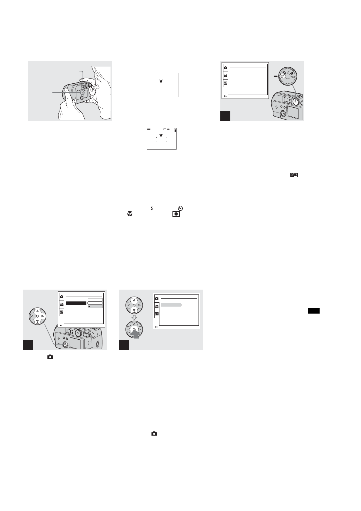
DSC-P71/P71M
Shooting with the finder
Finder
DISPLAY/
LCD
ON/OFF
button
The finder is convenient when you want to
save battery power, or when it is difficult to
confirm the image using the LCD screen.
Each time you press the DISPLAY/LCD
ON/OFF button, the display changes in the
following order.
When the LCD screen display is off (only
warning messages are displayed)
r
LCD screen display is OFF
r
Screen display is set to ON.
2048
4
• For further details on the items displayed, see
page 103.
• Just as with the AE/AF lock indicator on the
LCD screen display, when the AE/AF lock
lamp of the Finder section stops flashing and
remains lit, you can start shooting again
(page 26).
• When the LCD screen display is turned off, the
digital zoom does not function (page 28).
• When the LCD screen display is turned off, if
you press the (Flash mode)/ (Self-timer)/
(Macro, DSC-P71) or (Spot lightmetering, DSC-P31), the image will be
displayed on the screen for approximately 2
seconds so you can check or change the setting.
Shooting with the date and
time inserted
CAMERA
MOVING IMAGE :
DATE/TIME :
DIGITAL ZOOM :
RED EYE REDUCTION :
AF ILLUMINATOR :
SELECT
MPEG MOVIE
OFF
ON
OFF
OFF
1
, Turn the mode dial to SET UP.
The SET UP menu is displayed.
• When images are shot with the date and time
inserted, the date and time cannot be removed
later.
• When shooting images with the date and time
inserted, the actual date and time are not
displayed on the LCD screen, instead, “ ” is
displayed in the upper left portion of the LCD
screen. The actual date and time are displayed
when the image is played back.
• When you have chosen a date format, you can
choose [Insert the correct date and time]
(page 21), and the information will be inserted
in the format you chose.
• The “DIGITAL ZOOM” item is not displayed
on the SET UP screen of the DSC-P31
(page 28).
32
OK
2
,
Select (
on the control button and
press
Select “
and press
CAMERA
B
.
DATE/TIME
B.
CAMERA
MOVING IMAGE :
DATE/TIME :
DIGITAL ZOOM :
RED EYE REDUCTION :
AF ILLUMINATOR :
DAY&TIME
DATE
OFF
) using
” using
v/V
v/V
CAMERA
MOVING IMAGE :
DATE/TIME :
DIGITAL ZOOM :
RED EYE REDUCTION :
AF ILLUMINATOR :
SELECT
3
, Choose the type of data to be
inserted using v/V on the
control button, then press the
center z.
DAY/TIME: Inserts the day and the time of
shooting into the image
DATE: Inserts the year, the month and the
date of shooting into the image
OFF: Does not insert date/time data into the
image
After the setting have been completed, turn
the mode dial to , and continue your
shooting.
• You can also carry out this operation when the
mode dial is set to SCN.
• The settings made here will be saved even
when the power is turned off.
MPEG MOVIE
Y/M/D
ON
OFF
OFF
Shooting still images
1-14
33
Page 21
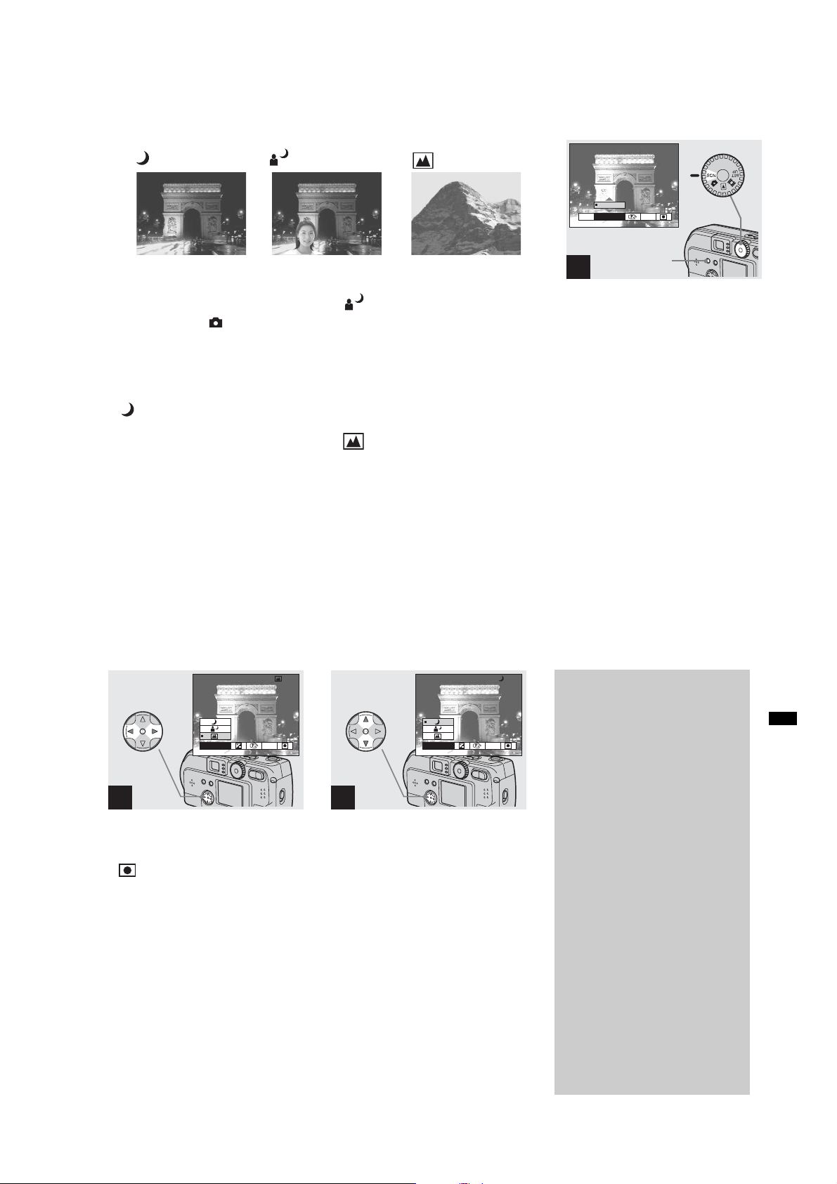
Shooting according to scene conditions
(SCENE SELECTION)
Twilight mode
Twilight portrait mode
Landscape mode
1
0EV
WB
EVSCN
MENU button
DSC-P71/P71M
0EV
Ordinarily shoot with the camera set to set
to Auto (Mode dial: ), but when shooting
at night, shooting people at night , or
shooting landscapes, use the modes listed
below to increase the quality of your
images.
Twilight mode
Under dark lighting conditions, you can
shoot using the Twilight mode, and still get
good images. However, because the shutter
speed is slower under these conditions, we
recommend you use a tripod.
• The flash cannot be used.
34
SCN
WB
2
, Select “SCN” using b/B on the
control button.
• (Spot light-metering) is not displayed on
the menu of the DSC-P31 (page 61).
Twilight portrait mode
Use this mode when shooting people in the
foreground at night.
Because the shutter speed is slow, it is
recommended that you use a tripod.
• Allows you to shoot images of people in the
foreground with distinct outlines without losing
the feeling that you are shooting at night.
• The flash can be used.
Landscape mode
Focuses on images far away, so is
convenient for shooting landscapes at a
distance.
• You cannot shoot in Macro mode.
SCN
WB
3
, Select the desired mode using
v/V on the control button.
The mode will be set to your choice.
When the setting is completed, press the
MENU button. The menu disappears from
the screen.
• When you cancel Scene selection, set the mode
dial to something other than SCN.
• The settings made here will be saved even
when the power is turned off.
, Turn the mode dial to SCN, and
press the MENU button.
The menu appears.
NR slow shutter
In Twilight or Twilight portrait mode,
when the shutter speed exceeds a 1/2
second, “NR” is displayed before the
shutter speed indication, and the
camera automatically changes to the
NR slow shutter mode.
The NR slow shutter mode removes
noise from recorded images, providing
clear, crisp images. To eliminate the
effects of vibration, use of a tripod is
recommended.
Press the shutter all the way down.
r
“CAPTURING” is displayed on the
screen.
Then the screen turns black.
r
Next, “PROCESSING” is displayed.
Finally, when “PROCESSING”
disappears, the image has been
recorded.
Shooting still images
1-15
35
Page 22
DSC-P71/P71M
Viewi
till i
Viewing images on the LCD screen of your
camera
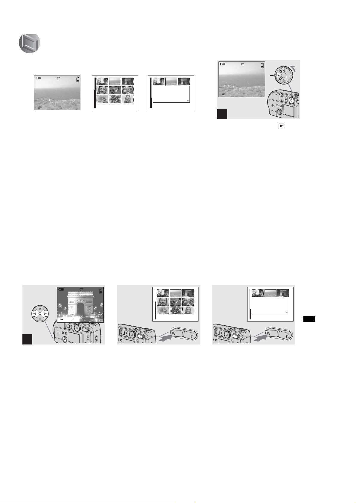
Single
(Single image display)
640
6/8
10:30
2002 7 4100-0028
FILE BACK/NEXT VOLUME
PM
You can see the images you shoot with this
camera almost immediately on the LCD
screen. This camera offers the following
three methods for viewing your images.
Single (Single image display)
You can view one image at a time,
occupying the entire screen.
Index (9 images display)
Nine images will be displayed
simultaneously in separate panels on the
screen.
Index (3 images display)
Three images will be displayed
simultaneously in separate panels on the
screen. Various items of image information
will also be displayed.
Index
(9 images display)
SINGLE
•
• For movies, see page 75.
• For information on the various symbols
Index
(3 images display)
APERTURE VALUE :
SHUTTER SPEED :
EXPOSURE VALUE :
:
ISO
SINGLE
•
displayed, see page 105.
F2.2
1/125
0.0
100
10:30
2002 7 4100-0028
PM
ng s
mages
Viewing single images
640
6/8
10:30
FILE BACK/NEXT
2002 7 4100-0028
PM
1
, Turn the mode dial to , and
turn on the power.
The last image you shot will be displayed.
36
640
10:30
2002 7 4100-0029
FILE BACK/NEXT
2
, Select Still Ima ge us ing b/B on
the control button.
b : Displays the previous image.
B : Displays the next image.
Viewing Index
(9 or 3 images display)
6/8
PM
, Press the Zoom W button once.
The display switches to the Index (9
images) screen.
SINGLE
•
, Press the Zoom W button once
more.
The display switches to the Index (3
images) screen.
To display the previous (next) Index
screen
Press v/V/b/B on the control button to
When you press v/V on the control button,
the remaining image information is
displayed.
move the yellow frame up/down/left/right.
To display the previous (next) Index
screen
Press b/B on the control button.
APERTURE VALUE :
SHUTTER SPEED :
EXPOSURE VALUE :
:
ISO
2002 7 4100-0028
SINGLE
•
F2.2
1/125
0.0
100
10:30
PM
Viewing still images
1-16
To return to the Single image screen
Repeatedly press the Zoom T button, or
press the center z on the control button.
37
Page 23
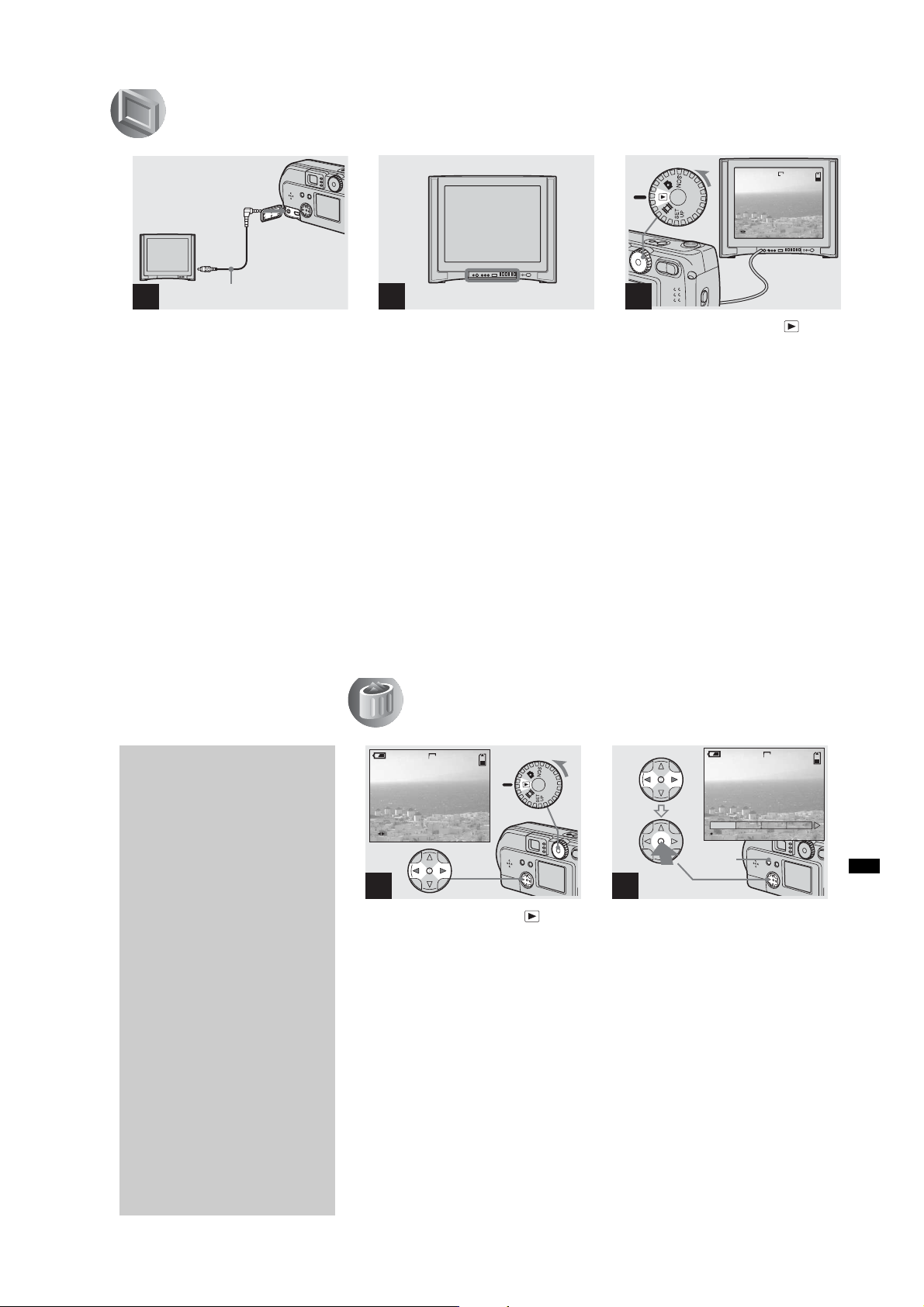
Viewing images on a TV screen
Deleti
till i
VIDEO OUT jack
DSC-P71/P71M
640
6/8
Video connecting cable
1
(supplied)
, Using the video connecting
cable, connect the VIDEO OUT
jack of the camera to the Image
of the TV set.
• Connect the video cable to the camera and the
TV set only after confirming that both are
turned off.
38
TV/Video toggle switch
2
, Turn on the power of the TV
set, and set the TV/Video
toggle switch of the TV to
“Video.”
• Depending on your TV set, the name and
location of this switch may be different.
FILE BACK/NEXT
10:30PM2002 7 4100-0028
3
, Turn the Mode dial to and
turn on the camera.
Press b/B on the control button to select an
image.
• When using this feature, it may be necessary to
switch the video output signal to match that of
your TV system (see page 98).
Watching the playback picture
on TV
If you want to view the playback
picture on a TV, you need a TV having
a video input jack and a video
connecting cable.
The color system of the TV must be the
same as that of your digital still camera.
Check the following list:
NTSC system
Bahama Islands, Bolivia, Canada,
Central America, Chile, Columbia,
Ecuador, Jamaica, Japan, Korea,
Mexico, Peru, Surinam, Taiwan, the
Philippines, the U.S.A., Venezuela, etc.
PAL system
Australia, Austria, Belgium, China,
Czech Republic, Denmark, Finland,
Germany, Holland, Hong Kong, Italy,
Kuwait, Malaysia, New Zealand,
Norway, Portugal, Singapore, Slovak
Republic, Spain, Sweden, Switzerland,
Thailand, United Kingdom, etc.
PAL-M system
Brazil
PAL-N system
Argentina, Paraguay, Uruguay
SECAM system
Bulgaria, France, Guiana, Hungary,
Iran, Iraq, Monaco, Poland, Russia,
Ukraine, etc.
Deleting images
2048
5/5
10:30
FILE BACK/NEXT
2002 7 4100-0028
PM
1
, Turn the Mode dial to and
turn on the camera. Press b/B
on the control button to select
an image to be deleted.
DELETE
OK
MENU
button
ng s
PROTECT
2048
mages
5/5
SLIDEPRINT
2
, Press the MENU button, press
b/B on the control button to
select “DELETE”, then press
the center z.
The image has not yet been deleted at this
point.
Deleting still images
39
1-17
Page 24
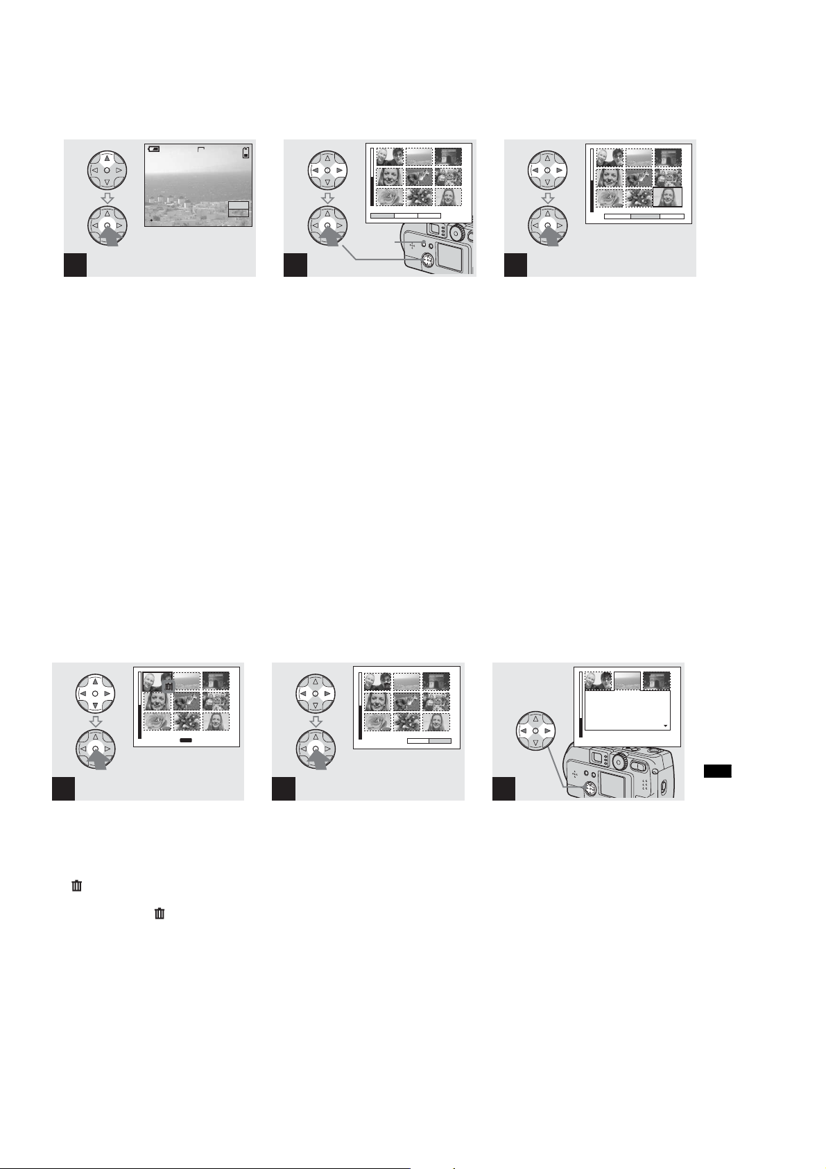
DSC-P71/P71M
Deleting images (continued)
2048
5/5
DELETE
OK
OK
CANCEL
3
, Select “OK” using v on the
control button, then press the
center z.
“MEMORY STICK ACCESS” is displayed
on the screen. When this message
disappears, the image has been deleted.
To cancel the deletion
Using V on the control button, choose
“CANCEL”, then press the center z.
Deleting on the Index (9 images) screen
PROTECT PRINTDELETE
MENU
button
1
, While an Index (9 images)
screen (page 37) is displayed,
press the MENU button, select
2
, Select “SELECT” using b/B on
the control button, then press
the center z.
“DELETE” using b/B on the
control button, then press the
center z.
To delete the entire screen
Select “ALL” using b/B on the control
button, then press the center z. Select
“OK” again, and press the center z. To halt
the deletion, select “EXIT”, then press the
center z.
DELETE
CANCEL
ALLSELECT
40
MENU
SET
•
TO NEXT
3
, Select the im age you w ant to
delete using v/V/b/B on the
control button then press the
center z.
The mark appears next to the selected
images. At this point, the images have not
yet been deleted. Put a mark next to all
of the images you want to delete.
• To cancel your selection, press the center z
one more time.
EXITDELETE OK
4
, Press the MENU button, select
“OK” using b/B on the control
button, then press the center
z.
When “MEMORY STICK ACCESS”
disappears, the images have been deleted.
To cancel the deletion
Using b on the control button, select
“EXIT”, then press the center z.
Deleting on the Index (3
images) screen
APERTURE VALUE :
SHUTTER SPEED :
EXPOSURE VALUE :
ISO
SINGLE
•
F2.2
1/125
0.0
100
:
2002 7 4100-0028
1
, While an Index (3 images)
screen (page 37) is displayed,
select the images you want to
delete using b/B on the control
button.
10:30
PM
Deleting still images
1-18
41
Page 25
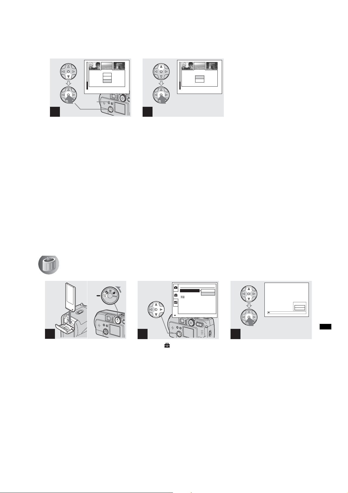
Deleting on the Index (3
images) screen (continued)
DSC-P71/P71M
PRINT
PROTECT
DELETE
2002 7 4100-0028
OK
•
MENU
button
2
, Press the MENU button, and
select “DELETE” using the V
on the control button, then
press the center z.
At this point, the images have not yet been
deleted.
42
10:30
DELETE
OK
CANCEL
10:30
PM
•
2002 7 4100-0028
OK
PM
3
, Select “OK” using v on the
control button, then press the
center z.
When “MEMORY STICK ACCESS”
disappears, the image has been deleted.
To cancel the deletion
on the control button to select
V
Use
“CANCEL”, then press the center z.
Formatting a “Memory Stick”
1
, Insert the “Memory Stick” you
want to format into the cam era.
Turn the mode dial to SET UP,
and turn on the power.
• The term “formatting” means preparing a
“Memory Stick” to record images; this process
is also called “initialization.” The “Memory
Stick” provided with this camera, and those
available commercially, are already formatted,
and can be used immediately. When you
format a “Memory Stick,” be aware that
all of the images in the “Memory Stick”
will be permanently deleted.
2
, Select
v/V on the control button,
select “FORMAT” by pressing
B. Then, press B, s e le c t " OK"
using v/V, and press the
center z.
To cancel the formatting
Select “CANCEL” using V on the control
button, then press the center z.
SETUP 1
FORMAT :
FILE NUMBER :
/LANGUAGE :
CLOCK SET :
OK
“”
(“SETUP 1”) using
OK
CANCEL
FORMAT
ALL DATA WILL BE ERASED
READY?
O K
OK
CANCEL
3
, Select “OK” using v/V on the
control button, then press the
center z.
The “FORMATTING” message appears.
When this message disappears, the format
is complete.
Deleting still images
1-19
43
Page 26
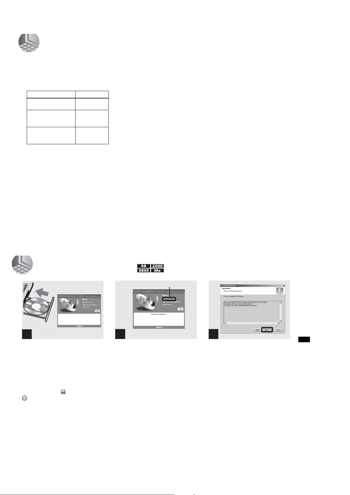
DSC-P71/P71M
C
till i
Copying still images to your computer
Follow the steps below to copy the images
you shot to your computer.
Steps required by your OS
(Operating System)
OS Steps
Windows 98/98SE/2000/MeSteps 1 to 5
Windows XP Steps 2 to 5
Mac OS 8.5.1/8.6/
9.0/9.1/9.2,
Mac OS X (v10.0/v10.1)
• Step 1 may be unnecessary depending on your
OS.
• After you complete the installation of the USB
driver, step 1 is unnecessary.
(pages 45 to 53)
(pages 46, 47, 49,
and 53)
Page 54
Recommended computer
environment
Recomm ended Windows environment
OS: Microsoft Windows 98, Windows
98SE, Windows 2000 Professional,
Windows Millennium Edition,
Windows XP Home Edition, or
Windows XP Professional
An OS installed at the factory (not
upgraded) is required for correct
44
operations. We cannot guarantee
operations for operating systems not
listed above.
CPU: MMX Pentium 200 MHz or faster
USB connector:
Provided as standard equipment
Recommended Macintosh environment
OS: Mac OS 8.5.1, 8.6, 9.0, 9.1, 9.2, or
Mac OS X(v10.0/v10.1)
An OS installed at the factory is
required for correct operations. For
the following models, update your
OS to Mac OS 9.0 or 9.1.
– iMac with Mac OS 8.6 installed at
the factory, and a slot loading type
CD-ROM drive
–iBook or Power Mac G4 with the
Mac OS 8.6 installed at the factory
USB connector:
Provided as standard equipment
• If you connect two or more USB devices to
your computer at one time, some devices,
including your camera, may not work,
depending on the type of USB device.
• Operations are not guaranteed when using a
USB hub.
• Operations are not guaranteed for all the
recommended environments mentioned above.
opying s
mages to your computer
USB mode
There are two modes for a USB connection,
“NORMAL” and “PTP” modes. The
factory setting is the “NORMAL” mode.
This section describes the USB connection
using the “NORMAL” mode.
Communication with your
computer (for Windows users
only)
If you recover your computer from the
suspend or sleep mode, communication
between your camera and your computer
may not recover at the same time.
When a USB connector is not
provided on your computer
When neither a USB connector nor a
“Memory Stick” slot is provided, you can
copy images using an additional device. See
the Sony Website for details.
1 Installing the USB driver
Opening window
1
, Turn on your computer, and
insert the s u pplied C D-ROM
into the C D -ROM drive.
Do not connect your camera to your
computer at this time.
The opening window appears. If it does not
appear, double-click (My Computer) t
(ImageMixer) in order.
• This section describes how to establish a USB
connection using Windows Me as an example.
Required operations may be different
depending on your OS.
•Shut down all other applications before
installation of the driver.
• When you are using Windows 2000, log on as
Administrators.
2
, Click “USB Driver” on th e
opening window.
The “InstallShield wizard” appears.
Click here
3
Click here
, Click “Next.” When the
“Information” window
appears, click “Next,” and eject
the CD-ROM.
The USB driver installation starts. When
the installation is completed, the window
informs you of completion.
Copying still images to your computer
1-20
45
Page 27
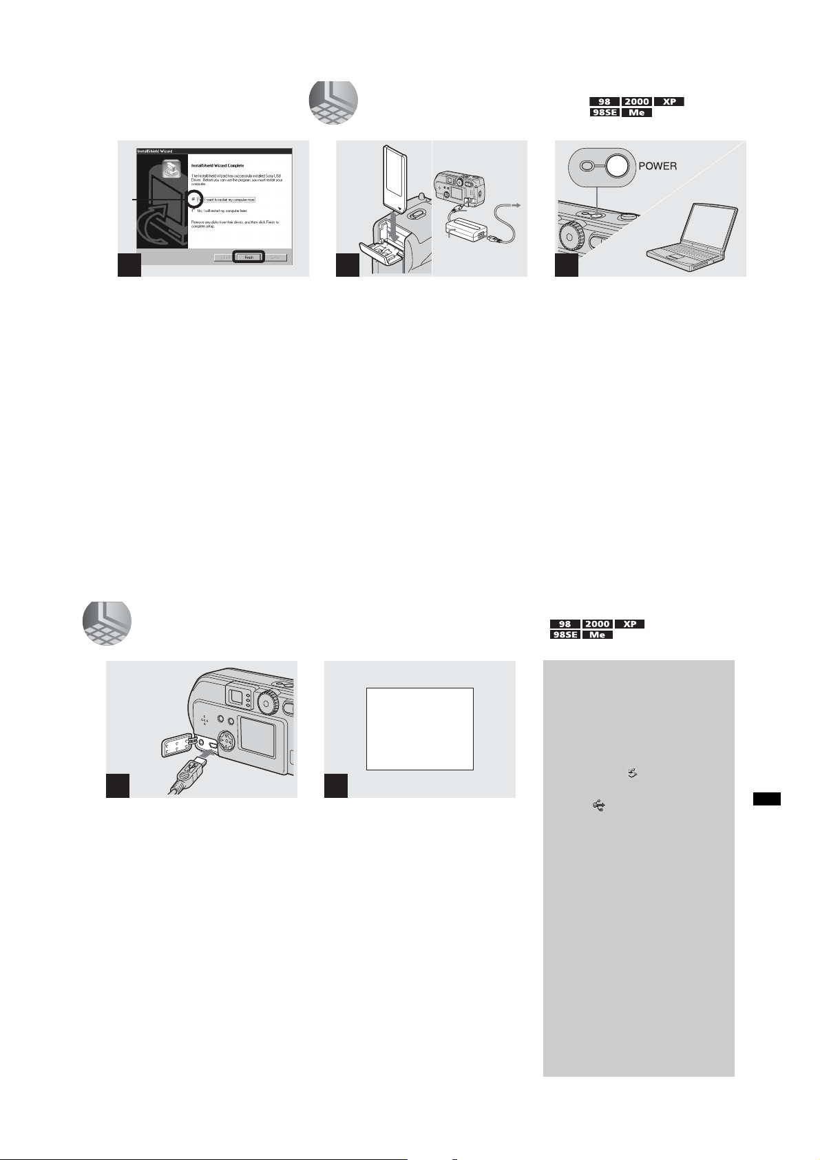
2 Preparing your camera
3
DSC-P71/P71M
1
4
, Click “Yes, I want to restart my
computer now,” then click
“Finish.”
Your computer restarts. Then, you can
establish the USB connection.
• You can use the “PIXELA ImageMixer for
Sony” software to copy images to your
computer. To install this software, click
“PIXELA ImageMixer,” on the operating
window, then follow instructions on each
window.
• Be sure to install DirectX when using the
“PIXELA ImageMixer for Sony” software.
Click “DirectX” and follow instructions on
each window. Your computer restarts when the
installation is completed.
46
“Memory
Stick”
1
AC power 2
adaptor
3
To the
wall outlet
(mains)
, Insert the “M emory Stick” with
the images you want to copy
into the camera. Connect the
camera and the AC power
adaptor, and plug the adaptor
into a w all outlet (m a in s ).
• For further details on the “Memory Stick,” see
page 23.
• For further details on the AC power adaptor,
see page 19.
2
, Turn on the PC and your
camera.
3 Connecting your camera to your computer
USB MODE
NORMAL
a a a a
1
, Open the jack cover, and
connect the supplied USB
cable to your camera. Then,
connect the other end of the
USB cable to your computer.
• When using a desktop computer, connect the
USB cable to the USB connector on the rear
panel.
• When using Windows XP, the copy wizard
automatically appears on the desktop. Proceed
to page 49.
2
“USB MODE NORMAL” appears on the
LCD screen of your camera. When a USB
connection is established for the first time,
your computer automatically runs the used
program to recognize your camera. Wait for
a while.
• If “USB MODE NORMAL” is not shown,
confirm that “USB CONNECT” is set to
“NORMAL” in the SET UP settings (page 98).
Removing the USB cable
from your computer or the
“Memory Stick” from your
camera during a USB
connection
For Windows 2000, Me, or XP users
1 Double-click at the lower-right
corner of the desktop.
2 Click (Sony DSC), then click
“Stop.”
3 Confirm the device on the
confirmation window, then click
“OK.”
4 Click “OK.”
5 Disconnect the USB cable or
remove the “Memory Stick.”
For Windows 98 or 98SE users
Carry out only Step 5 above.
Copying still images to your computer
47
1-21
Page 28
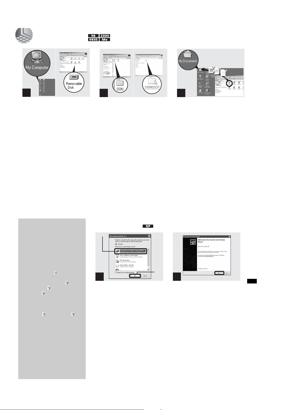
DSC-P71/P71M
1
4 Copying images
1
, Double-click “My Computer,”
then double-click “Removable
Disk.”
The contents of the “Memory Stick”
inserted in your camera appear.
• This section describes an example of copying
images into the “My Documents” folder.
• When using Windows XP, see pages 49 to 51.
• When the “Removable Disk” icon is not sho wn,
see the next page.
• You can use the “PIXELA ImageMixer for
Sony” software to copy images to your
computer. For details, see the software’s help
files.
48
When a removable disk
icon is not shown
1 Right-click “My Computer,” then
click “Property.”
The “System Property” window
appears.
2 Confirm if other devices are already
installed.
1 Click “Device Manager.”
2 Double-click “ Other
Devices.”
3 Confirm if there is a “ Sony
DSC” or “ Sony Handycam”
with a mark.
3 If you find either of the devices
above, follow the steps below to
delete them.
1 Click “ Sony DSC” or “
Sony Handycam.”
2 Click “Delete.”
The “Device deletion
confirmation” window appears.
3 Click “OK.”
The device is deleted.
2 3
, Double-click “D C IM,” then
double-click “100MSDCF.”
The “100MSDCF” folder opens.
• The “100MSDCF” folder contains the image
files you shot using your camera.
• The folder names vary depending on the type of
images they contain (page 51).
4 Copying images (for
Windows XP users)
2
1
, Click “Copy pictures to a folder
on my computer using
Microsoft Scanner and Camera
Wizard, ” then click “OK .”
The “Scanner and Camera Wizard”
appears.
• When following the steps on page 47, the copy
wizard appears on the desktop of your
computer.
, Drag and drop the image files
into the “My Documents”
folder.
The image files are copied to the “My
Documents” folder.
• When you try to copy an image to a folder in
which an image with the same file name is
stored, the overwrite confirmation message
appears. When you want to overwrite the
existing image with the new one, click “Yes.”
When you do not want to overwrite it, click
“No,” then change the file name.
2
, Click “Next.”
The images stored in the “Memory Stick”
are displayed.
Copying still images to your computer
Try the USB driver installation again
using the supplied CD-ROM (page 45).
49
1-22
Page 29
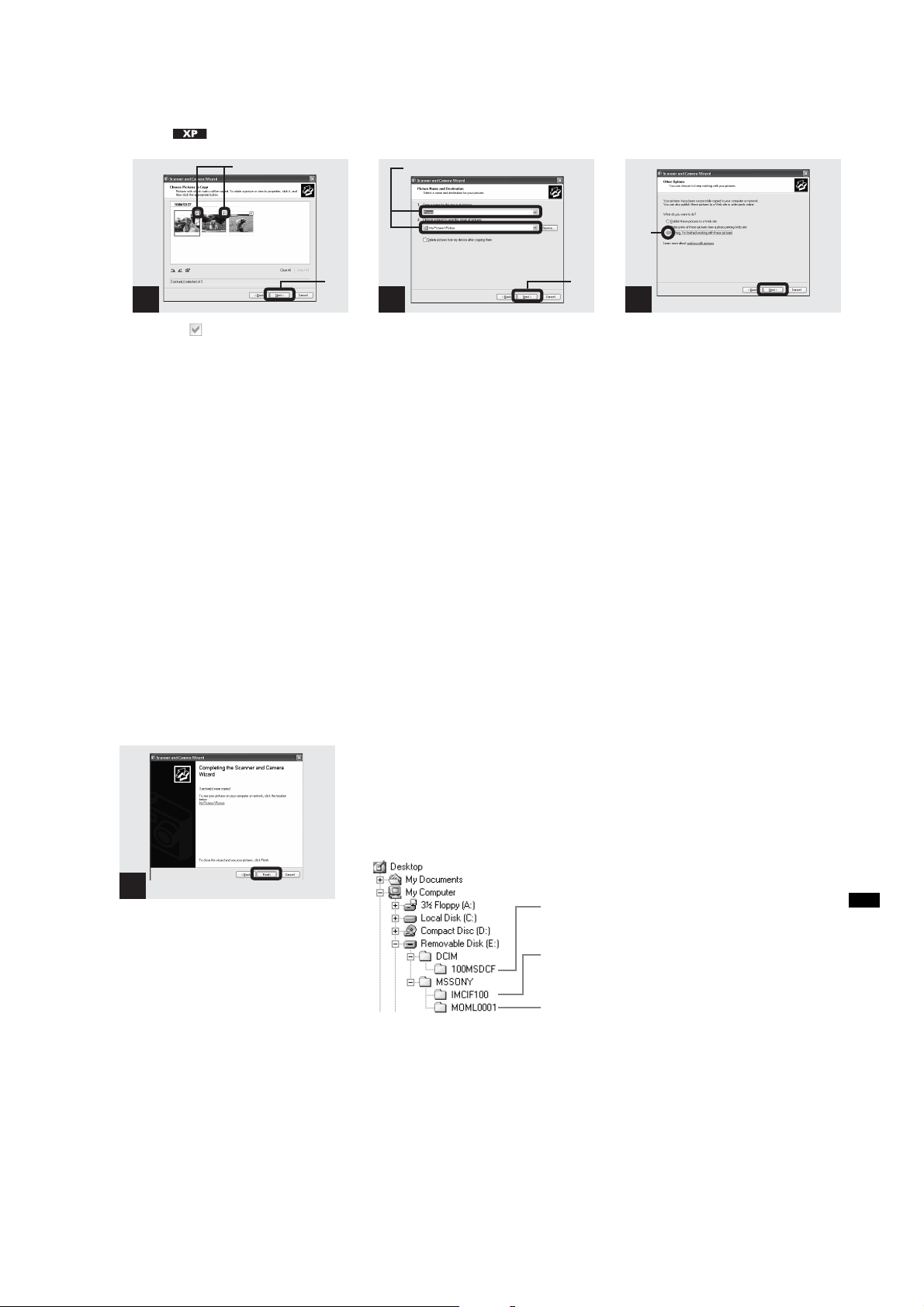
4 Copying images (for Windows XP
users) (continued)
DSC-P71/P71M
1
3
, Click to remove the
checkmark from any images
you do not want to copy to
your computer, then click
“Next.”
The “Picture Name and Destination”
window appears.
1
1
2
4
, Specify the image file names to
be copied and the copy
destination.
Copying of the images starts. When the task
is completed, the “Other Options” window
appears.
• Copy images into the “My Documents” folder.
2
5
2
, Click “Nothing. I’m finished
working with these pictures,”
then click “Next.”
The “Completing the Scanner and Camera
Wizard” window appears.
50
6
, Click “Finish.”
The wizard closes.
• When you want to continue copying other
images, disconnect the USB cable once and
reconnect it. Then, follow the process from
Step 1.
Click here
Image file storage destinations and file names
The image files recorded with your camera
are grouped as folders in the “Memory
Stick,” depending on the recording modes.
Example: when viewing folders on
Windows Me
Folder containing still image/Clip Motion/
Multi Burst mode image data
Folder containing E-mail mode image data
Folder containing Movie data
Copying still images to your computer
1-23
51
Page 30
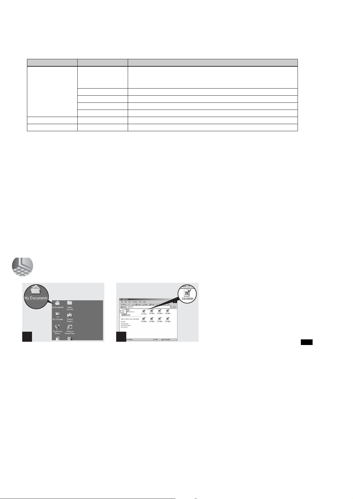
DSC-P71/P71M
Image file storage destinations and file names (continued)
Folder File name File meaning
100MSDCF DSC0ssss.JPG • Still image file s s h ot n o rm a lly
IMCIF100 DSC0ssss.JPG
MOML0001 MOV0ssss.M P G
Note on the table
• The meanings of the file names are as above:
ssss stands for any number within the range from 0001 to 9999.
• The numerical portions of the following files are the same.
–A small-size image file shot in E-MAIL mode and its corresponding image file
–An image file shot with Clip Motion and its corresponding index image file
CLP0ssss.GIF
CLP0ssss.THM
MBL0ssss.GIF
MBL0ssss.THM
•Still image files s h ot in
–E-MAIL mode (page 65)
–Multi Burst mode (page 64)
• Clip Motion files shot in NORMAL mode (page62)
• Index image files of Clip Motion files
• Clip Motion files
• Index image files of Clip Motion files
• Small-size image files shot in E-MAIL mode (page65)
• Movie files
shot in MOBILE mode (page 62)
shot normally (page 74)
shot in NORMAL mode
shot in MOBILE mode
52
5 Viewing the images on your computer
1 2
, Double-click “My Documents”
on the desktop.
The “My Documents” folder opens.
• This section describes the steps followed for
copying images to the “My Documents” folder
on page 48.
• When using Windows XP, click “Start”t“My
Documents” in that order.
• You can use the “PIXELA ImageMixer for
Sony” software to view images on your
computer. For details, see the software’s help
files.
, Double-click the desired image
file.
The image file opens.
Copying still images to your computer
1-24
53
Page 31

For Macintosh users
Bef
DSC-P71/P71M
Follow the steps below, according to your
OS.
OS Steps
Mac OS 8.5.1/8.6/9.0
Mac OS 9.1/9.2/
Mac OS X(v10.0/v10.1)
1
Installing the USB driver
Steps 1 to 5
Steps 2 to 5
(For Mac OS 8.5.1, 8.6, or 9.0 users
only)
1 Turn on your computer, and set the
supplied CD-ROM to the CD-ROM
drive.
The “PIXELA ImageMixer” window
appears.
2 Double-click (Setup Menu).
3 Click “USB Driver.”
The “USB Driver” window appears.
4 Double-click the icon of the hard disk
containing the OS to open the window.
5 Drag and drop the following two files
from the window opened in step 3 to the
System Folder icon in the window
opened in step 4.
•Sony USB Driver
•Sony USB Shim
54
6 When the message “Do you want to put
these items into Extension Folder?” is
shown, click “OK.”
7 Restart your computer.
2
Preparing your camera
For details, see page 46.
3
Connecting your camera to
your computer
For details, see page 47.
Removing the USB cable from your
computer or the “Memory Stick” from
your camera during a USB connection.
Drag and drop the drive icon of the
“Memory Stick” to the “Trash” icon, then
remove the USB cable or “Memory Stick.”
* If you are using Mac OS X, remove the USB
cable, etc., after you have turned your computer
off.
4
Copy in g images
1 Double-click the newly recognized icon
on the desktop.
The contents of the “Memory Stick”
inserted in your camera appear.
2 Double-click “DCIM.”
3 Double-click “100MSDCF.”
4 Drag and drop the image files to the hard
disk icon.
The image files are copied to your hard
disk.
5
Viewing the images on your
computer
1 Double-click the hard disk icon.
2 Double-click the desired image file in
the folder containing the copied files.
The image file opens.
• You can use the “PIXELA ImageMixer for
Sony” software to copy images to your
computer and view the images on your
computer. To install the software, insert the
supplied CD-ROM drive, then click “PIXELA
ImageMixer” on the opening window and
follow the instructions on each window. For
details, see the software's help files.
How to setup and
operate your camera
Here we will explain the most commonly
used menus and the SET UP screen.
Control button
MENU button
Mode Dial
Changing menu settings
a Press the MENU button and
the me nu will be displayed.
0EV
0EV
WB
EV ISO
b Select the setting item you
want to change using b/B on
the control button.
The letters and symbols of the item
you select will turn yellow.
∞
7.0m
3.0m
1.0m
0.5m
CENTER AF
MULTI AF
WB
FOCUS ISO
c Select the desired setting
using v/V on the control
button.
The frame of the selected setting will
turn yellow, and the setting will be
made.
• (Spot light-metering) is not displayed on
the menu of the DSC-P31 (page 61).
To turn off the menu display
Press the MENU button.
Changing items in the SET
UP screen
a Turn the Mode dial to SET UP,
and the SET UP screen
appears.
CAMERA
MOVING IMAGE :
DATE/TIME :
DIGITAL ZOOM :
RED EYE REDUCTION :
AF ILLUMINATOR :
SELECT
MPEG MOVIE
OFF
ON
OFF
ON
ore advanced operations
b Select the setting item you
want to change using v/V/b/B
on the control button.
The frame of the item you select will
turn yellow.
SETUP 2
LCD BRIGHTNESS :
LCD BACKLIGHT :
BEEP :
VIDEO OUT :
USB CONNECT :
POWER SAVE :
SELECT
c Press the center z on the
control button to enter the
setting.
• On the DSC-P31, the "DIGITAL ZOOM"
(page 28) and "POWER SAVE" (page 16)
items are not displayed.
To turn off the SET UP screen
display
Turn the Mode dial to anything other than
SET UP.
SHUTTER
ON
OFF
Before advanced operations
55
1-25
Page 32

DSC-P71/P71M
Ad
till i
Adjusting the
exposure
– EV adjustment
Mode dial setting: /SCN/
Used when you want to change the
automatic exposure to one of your own
choice. The value can be set over a range
from +2.0EV to –2.0EV, in 1/3EV
increments.
Control button
MENU button
Mode dial
a Turn the Mode dial to , SCN,
.
or
b Press the MENU button.
The menu appears.
c Select “ ”
using b/B.
The value of the exposure adjustment
is displayed.
2048
4
0EV
0EV
WB
EV ISO
d Select the exposure
adjustment value.
Select the exposure adjustment value
using
Make your adjustment while
confirming the brightness of the
background of the subject on the LCD
screen.
v/V
.
To return to auto adjust mode
Return the exposure adjustment value to 0
EV.
• (Spot light-metering) is not
displayed on the menu of the DSC-P31
(page 61).
•When the subject is at the brightest or
darkest ends of the range, or when you are
using the flash, the adjustment value set
may not actually be used.
vanced s
mage shooting
Shooting techniques
In normal shooting, the camera makes
automatic exposure adjustments. Check the
image to be shot, if it looks like the image
below, you should make manual adjustments.
If you are shooting a back-lit person or a
snowy scene, make your adjustments in the +
plus direction; if you have a dark subject that
fills the screen, making your adjustments in the
– direction should give the best results.
Inadequate exposure
t Adjust in the + direction
Appropriate exposure
Overexposed t Adjust in
the – direction
56
Adjusting color tones
– WHITE BALANCE
Mode dial setting: /SCN/
When shooting images using automatic
features, the white balance is set
automatically in response to the condition
of the subject, and the overall color balance
is adjusted accordingly. When you want to
fix the conditions under which the image is
captured, or when shooting under special
lighting conditions, you can select the
settings manually.
AUTO (no display)
The white balance is adjusted
automatically.
Daylight ( )
Used when shooting outdoors, and for
shooting at night, under neon lights, for
fireworks, sunrises and sunsets.
Cloudy ( )
Used when shooting under a cloudy sky.
Fluorescent ( )
Used when shooting under fluorescent
lights.
Incandescent ( )
•Used when shooting, for example, at a
party, where the lighting conditions
change often
•Used in a studio, or under video lights
•Used when shooting under sodium or
mercury lights
Control button
MENU button
Mode dial
a Turn the mode dial to , SCN,
or
.
b Push the menu button.
The menu appears.
c Select WB using b/B, then
select the desired setting
using v/V.
To return to automatic settings
In Step 3, select “AUTO”.
• Under fluorescent lights that flicker, e ven if you
choose Fluorescent, you may feel that the
overall color of the image may show
differences from the actual color.
• When the flash is triggered, the manual setting
is cancelled, and the shooting of the image is
done in “AUTO” mode.
Shooting techniques
The color of the subject that you see will be
captured according to the lighting
conditions. Under the bright summer sun,
everything will appear bluish, under a light
sources like a light bulb, white objects will
appear will appear reddish. The human eye
has an excellent ability to adjust. Even when
lighting conditions change, the eye can
adjust and recognize the correct color almost
instantly. Ho wever, digital still cameras are
greatly influenced by light. Normally, this
camera adjusts automatically, but if you
notice that the color of the entire image
seems to be a bit unnatural when replaying
an image on the LCD screen, it is
recommended that you adjust the white
balance.
Advanced still image shooting
1-26
57
Page 33

DSC-P71/P71M
Choosing a focus
method
Mode dial settings: /SCN/
Multipoint AF
When you use Multipoint AF, it calculates
the distance in three places, in the center of
the image, and to both the left and right of
the center, you can shoot with the auto focus
function without being dependent on the
composition of the image. It is useful when
it is difficult to focus on the subject because
it is not in the center of the frame.
Center AF
You can focus automatically using the AF
range finder in the center of the frame.
Control button
MENU button
Mode dial
a Turn the Mode dial to either ,
SCN, or .
b Press the MENU button.
c Select “
” using b/B, select
9
“MULTI AF” or “CENTER AF”
using v/V.
The focus is adjusted automatically using
the AF range finder. The color of the range
finder frame changes from white to green.
Multipoint AF
2048
4
Center AF
2048
4
• When you are shooting movies (MPEG
MOVIE) and you choose Multipoint AF, the
distance to the center of the screen is estimated
as an average, so the AF works even with a
certain amount of vibration. The Center AF
automatically focuses only on the center of the
image, so it is convenient when you want to
focus only on what you aim at.
• When you use Digital zoom or AF illuminator,
priority AF movement is given to subjects in or
near the center of the frame. In this case, the AF
range finder isn’t displayed.
58
Shooting with the AF lock
using Center AF
If it is difficult to focus because the subject
is not in the center of the frame, you can
focus in this situation using the AF range
finder. For example, when you are shooting
two human subjects, and there is a gap
between them, the camera may focus on the
background visible in the gap. In a case like
this, use AF lock to ensure the subjects are
in correct focus.
• When you are using AF lock, you can capture
an image with the correct focus even if the
subject is at the edge of the frame.
a Compose the shot so that the
subject is centered in the AF
range finder, and press the
shutter halfway down.
First, the focus for the subject you are
aiming at will be adjusted. When the
AE/AF lock indicator stops flashing
and stays lit, and there is a beeping
sound, focus adjustment is completed.
2048
4
F2.1
50
AF range finder
AE/AF lock
indicator
b Return to the fully composed
shot, and press the shutter
down again.
When you hear a beeping sound, the
image will be recorded with the proper
focus for the human subjects.
2048
4
F2.1
50
• You can carry out the AF lock adjustment
process any number of times, as long as you do
it before you press the shutter.
Advanced still image shooting
1-27
59
Page 34

DSC-P71/P71M
Setting the distance
to the subject
– Focus preset
Mode dial setting: /SCN/
When shooting an image using a previously
set distance to the subject, or when shooting
a subject through a net or through window
glass, it is difficult to get the proper focus
using the automatic focus function. This is
when use of the Focus preset is convenient.
Control button
MENU button
Mode dial
You can select from the following
distance settings.
0.5m, 1.0m, 3.0m, 7.0m,
(unlimited
∞
distance)
2048
4
∞
7.0m
3.0m
1.0m
0.5m
CENTER AF
MULTI AF
FOCUS
1.0m
9
WB
ISO
To return to automatic adjustment
Press the MENU button again, select “9”,
then select “MULTI AF” or “CENTER
AF”.
• (Spot light-metering) is not displayed on
the menu of the DSC-P31 (page 61).
• The focus distance settings include a small
margin of error. Use them as guidelines only.
• If you point the lens up or down, the error
increases (DSC-P71 only).
Adding special effects
– Picture effect
Mode dial setting: /SCN/
You can add special effects to bring out the
contrast in your images.
SOLARIZE B&W
Like an illustration
with clearly delineated
bright and dark
portions
SEPIA NEG.ART
In black and white
a Turn the Mode dial to , SCN,
.
or
b Press the MENU button.
The menu appears.
c Select “
” using b/B, then
9
select the distance to the
60
subject using v/V.
a Turn the Mode dial to , SCN,
.
or
b Press the MENU button.
The menu appears.
c Select “PFX” (P. EFFECT)
using b/B, th e n s e le c t th e
desired mode using v/V.
To cancel Picture Effect
In Step 3, select “OFF”
Spot light-metering
Mode dial setting: /SCN/
When there is reflected light, or the
background of the subject provides a very
high contrast, you can adjust the focus to
that most appropriate for your subject. You
can aim at a particular point, and meter the
light to adjust the focus for that point.
• When the place you want to focus on and the
place you are using Spot light-metering on are
the same, it recommended that you use Center
AF (page 58).
Control button
MENU button
Mode dial
Shutter button
Colored to look like an
old photograph
Made to look like a
negative image
For the DSC-P71
a Turn the Mode dial to , SCN,
.
or
b Press the MENU button.
The menu appears.
c Select “” using b/B, then
select “ON” using v/V.
The Spot light-metering aiming point
is displayed.
2048
4
Spot lightmetering
aiming point
d Aim the Spot light-metering
aiming point at the spot you
want to shoot, then shoot your
image.
Advanced still image shooting
1-28
61
Page 35

DSC-P71/P71M
To cancel Spot light-metering
Press the MENU button again and select
“” using b/B on the control button,
select “OFF” then using v/V. The Spot
light-metering aiming point disappears, and
the camera returns to normal lightmetering.
For the DSC-P31
a Turn the Mode dial to , SCN,
.
or
b Press B () on the control
button to turn Spot lightmetering on.
The Spot light-metering aiming point
is displayed.
c Aim the Spot light-metering
aiming point at the spot you
want to shoot, then shoot your
image.
To cancel Spot light-metering
Press B () on the control button to turn
Spot light-metering off. The Spot lightmetering aiming point disappears, and the
camera returns to normal light-metering.
Shooting multiple
frames
– Clip Motion
Mode dial setting:
You can shoot a number of still images
consecutively (GIF animation). Because the
file size is small, these images are ideal for
use on a home page, or for attaching to an email message.
• Clip Motion images are restricted to color
levels of 256 colors and below. This is a
characteristic of GIF format recording. For this
reason, the image quality of some images may
deteriorate.
NORMAL (160×120)
The maximum number of frames you can
shoot in one Clip Motion shot is ten. This is
the best choice for use on a home page.
MOBILE (120×108)
Two frames is the maximum number that
can be shot in Clip Motion in this mode.
• MOBILE mode has strict file size limits, so
picture quality falls accordingly.
• For the number of images you can record using
Clip Motion, see page 91.
62
Before using Clip Motion
In “MOVING IMAGE” in SET UP, select
“CLIP MOTION” (pages 55, 97).
Control button
MENU button
Mode dial
Shutter button
a Turn the Mode dial to .
b Press the MENU button.
The menu appears.
c Select “ ” (IMAGE SIZE)
using b/B, a n d s e le c t th e
desired mode useing v/V.
d Shoot one frame.
MAKING “CLIP MOTION”
e Shoot the next frame.
Press the shutter once to shoot the next
frame, then repeat this operation until
you have shot the desired number of
frames.
f Press the center z.
All of the frames will be saved in the
“Memory Stick.”
• If you do not complete Step 6, the image will
not be saved in the “Memory Stick.” Up to that
point, the image is saved temporarily in the
camera.
• In Clip Motion mode, the date and time will not
be recorded.
• When you view Clip Motion images using the
Index screen, the images may appear different
from the actual image recorded.
• GIF files made on other cameras may not
display correctly on this camera.
To delete shot images in the
midst of shooting
1 In Steps 4 or 5 on the previous page,
press b (7)
Shot images will be played back in
order, playback stops when the last
image is reached.
2 Press the MENU button, select either
“DELETE LAST”, or “DELETE ALL”,
and press the center z.
3 Select “OK”, then press the center z. If
you chose “DELETE LAST” in Step 2,
repeat Steps 1 to 3 to delete the images
in order, from the latest one shot.
Advanced still image shooting
1-29
63
Page 36

DSC-P71/P71M
Shooting in Multi
Burst mode
– Multi Burst mode
Mode dial setting:
Pressing the shutter once records 16 frames
in a row. This is convenient for checking
your form in sports, for example. You can
set the interval between frames using the
menu.
Before beginning the operation, select
“MULTI BURST” in “MOVING IMAGE”
(page 55).
Control button
MENU button
Mode dial
Shutter button
a Turn the Mode dial to .
b Press the MENU button.
The menu appears.
c Select “” using b/B, th e n
select the desired betweenframe interval using v/V.
You can choose the between-frame
interval from among the following.
NTSC: 1/7.5 sec., 1/15 sec., 1/30 sec.
PAL: 1/6.3 sec., 1/12.5 sec., 1/25 sec.
(For information on NTSC/PAL, see
page 95.)
1/7.5
1/7.5
1/15
1/30
INTERVAL
PFX
d Press the shutter.
16 frames will be recorded as one
image (image size: 1280
• When you play back images recorded with this
camera in Multi Burst mode, the 16 frames will
be played back in order, with a fixed interval
between them.
• When the images are played back on a
computer, the 16 frames you shot will all be
displayed at the same time as part of one image.
960).
×
• When Multi Burst images are played back on a
camera without the Multi Burst feature, the 16
frames will all be displayed at the same time, as
part of one image, just as they are on a
computer.
• For the number of images that can be recorded
using the Multi Burst mode, see page 91.
• In Multi Burst mode, the date and time cannot
be displayed.
64
Deleting shot images
When using this mode, you cannot delete
only certain frames. When you delete
images, all 16 of the frames will be deleted
at the same time.
a Turn the Mode dial to
b Press the MENU button and
select “DELETE” from the
menu, then press the center z.
c Select “OK”, and press the
center z.
All of the frames are deleted.
.
Shooting still images
for e-mail
– E-MAIL
Mode dial setting: /SCN
You can shoot images and save them in a
file that is small enough to attach to an email message (see page 24 for available file
sizes).
Control button
MENU button
Mode dial
Shutter button
a Turn the Mode dial to , or
SCN.
b Press the MENU button.
The menu appears.
c Select “MODE” (recording
mode) using b/B, the n se le c t
“E-MAIL” using v/V.
d Shoot your image.
To return to Normal mode
In Step 3, select “NORMAL.”
• For instructions on how to attach your images
to an e-mail message, refer to the Help files of
the e-mail software you are using.
Advanced still image shooting
1-30
65
Page 37

DSC-P71/P71M
Ad
till i
Enlarging a portion of
a still image
Mode dial setting:
You can magnify an image up to five times
the size of the original image. You can also
record the magnified image as a new file.
Control button
MENU button
Mode dial
Zoom button
Enlarging an image
zoom
a Turn the Mode dial to
– Playback
.
b Display the image you want to
enlarge.
c Press the T zoom button, the
image will be enlarged.
d Press the control button
repeatedly to select a portion
of the image to e n la rge.
Press v
Press
b
Press V
v:To view a portion of the top of the
image
V:To view a portion of the bottom of
the image
b:To view a portion of the left side
of the image
B:To view a portion of the right side
of the image
Press
B
vanced s
mage viewing
e Press the T zoom button
repeatedly, the portion of the
image s e le c ted in Ste p 4 will
be enlarged .
To cancel enlarged viewing
Press the center z.
• You cannot use Playback zoom with movies
(MPEG MOVIE)/Clip Motion/Multi Burst
images
• If you press the W zoom button when you are
viewing images that have not been enlarged,
the Index screen will appear (page 37).
• The images displayed in Quick Review
(page 27) can be enlarged using the procedures
outlined in Steps 3 to 5.
66
Recording an enlarged
image
a After you have viewed an
b Select “TRIMMING” using B,
c Select the image size using v/
• The trimmed image will be recorded as the
• The trimmed image may suffer some
• You cannot trim an image using the 3:2 image
– Trimming
image using playback zoom,
press the MENU button.
then press the center z.
V, then press the center z.
The image will be recorded, and the
screen image will return to the size it
was before enlargement.
newest file, and the original image will be
retained.
deterioration in image quality
size.
Playing back
successive images
– Slide show
Mode dial setting:
You can playback recorded images in
succession, one after another. This is useful
for checking your images, or for giving a
presentation.
Control button
MENU button
Mode dial
a Turn the mode dial to
b Press the MENU button.
The menu appears.
c Select “SLIDE” using v/V, and
press the center z.
Select an interval from those listed
below.
INTERVAL settings
3 sec/5 sec/10 sec/30 sec/1 min
REPEAT
ON:Plays the images back repeatedly.
OFF:Plays through the images one
time and then stops.
d Select “ST A R T” using v/V/b/
B, then press the center z.
The slide show begins.
To cancel the Slide show setting
In Step 3, select “CANCEL”, then press
the center z.
.
Advanced still image viewing
1-31
67
Page 38

DSC-P71/P71M
Still i
ditti
To stop the playback of the slide
show
Press the center z, select “EXIT” using B,
then press the center z.
To fast forward or to go back to a
previous image during a slide
show
Press the B (Forward), or the b
(Backward).
• The interval settings are just guidelines. The
actual intervals will differ, based on factors lik e
the size of the image.
Rotating still images
Mode dial setting:
Images shot when holding the camera
vertically can be rotated and displayed
horizontally.
a Turn the mode dial to , and
display the image you want to
rotate.
b Press the MENU button.
The menu appears.
c Select “ROTATE” using b/B,
then press the center z.
d Select “ ” using v/V, and
rotate the image using b/B.
e Select “OK” using b/B, then
press the center z.
To cancel rotation
In Step 4, select “CANCEL”, then press
the center z.
• Protected images (page 69)/movies (MPEG
MOVIE)/Clip Motion/Multi Burst images
cannot be rotated.
• Images shot on other cameras may not rotate
correctly on this camera.
• When viewing images on a personal computer,
the image viewing software used may not
handle the rotation information correctly.
68
Protecting images
– Protect
Mode dial setting:
To prevent accidental erasure of an
important image, you can protect it.
Control button
MENU button
Mode dial
For single images
a Turn the mode dial to
.
b Display the image you want to
protect using b/B.
c Press the MENU button.
The menu appears.
d Select “PROTECT” using b/B,
then press the center z.
The image currently being displayed is
now protected, and a - (Protect)
mark is shown on the screen.
2048
5/5
PROTECT
SLIDEPRINT
DELETE
OK
To cancel the protection applied
to an image
In Step 4, press the center z again. The
- (Protect) mark disappears.
mage e
For Index (9 images) screen
a Turn the mode dial to , press
the W zo o m button once, th e
Index (9 image) screen
appears.
b Press the MENU button.
The menu appears
c Select “PROT EC T ” using b/B,
and press the center z.
d Select “SELECT” using b/B,
and press the center z.
The frame around the selected image
turns green.
e Select the imag e you want to
protect using the control
button, and press the center
z.
A - (Protect) mark will be attached
to the selected image.
ng
Still image editting
1-32
MENU
SET
•
TO NEXT
69
Page 39

DSC-P71/P71M
f To protect other images,
repeat Step 5.
g Press the MENU button.
The menu appears.
h Select “OK” using the B, then
press the center z.
The selected image will be protected.
To end the protection operation
Select “CANCEL” in Step 4 or select
“EXIT” in Step 8, then press the center z
To cancel protection of a
protected image
In Step 5, using the control button, select
an image for which you want to cancel
protection, and press the center z. Repeat
this operation for all of the images for
which you want to cancel protection. Then,
press the MENU button, select “OK”, and
press the center z.
To protect all of your images
In Step 4 select “ALL”, and press the
center z. Then select “ON”, and press the
center z.
To remove protection from all of
your images
In Step 4 select “ALL”, and press the
center z. Then select “OFF”, and press the
center z.
For Index (3 images) screen
a Turn the mode dial to , press
the W z oom button twice, the
Index (3 images) screen
appears.
b Move the image you want to
protect to the center using b/
B, and press the center z.
c Press the MENU button.
The menu appears
d Select “PRO TECT” using v/V,
and press the center z.
The center image is protected, and a
- (Protect) mark will be attached to
that image.
PRINT
PROTECT
DELETE
10:30
PM
2002 7 4100-0005
OK
•
e To protect other images, move
the image you want to protect
to the ce n te r u s in g b/B, and
repeat Step 4.
70
To remove protection from
previously protected images
In Step 4, select the image from which
you want to remove protection, and press
the center z. To remove protection from all
of your images, repeat this process for each
of them.
Changing image size
– Resize
Mode dial setting:
You can change the size of your images,
and record them as new files.
You can change your images to the
following sizes.
2048×1536 (DSC-P71 only), 1600×1200,
1280×960, 640×480
After the resizing is finished, the original
image is retained.
Control button
MENU button
Mode dial
c Press the MENU button.
The menu appears
d Select “RESIZE” using b/B,
then press the center z.
e Using v/V, select the new size,
then press the center z.
The resized image is recorded as the
newest file.
To stop the resizing process
In Step 5, select “CANCEL”, then press
the center z.
• Movies (MPEG MOVIE)/Clip Motion/Multi
Burst images cannot be resized.
• When images are resized from a smaller to a
larger size, the image quality will deteriorate.
• 3:2-sized images cannot be resized.
• If you try to resize a 3:2-sized image, black
bands will appear at the top and bottom of the
image.
Still image editting
a Turn the mode dial to
.
b Select the image for which the
size is to be changed using b/
B
.
1-33
71
Page 40

DSC-P71/P71M
Choosing images to
print
– Print mark
Mode dial setting:
You can designate certain images to be
printed.
This is convenient when you want to have
images printed in shops that follow DPOF
(Digital Print Order Format) specifications.
• Print marks cannot be attached to movies
(MPEG MOVIE) or images recorded using
Clip Motion.
• In E-MAIL mode, the Print mark will be
attached to the normal size image that was
recorded at the same time.
• You can attach a print mark to images shot
using Multi Burst mode; all the images will be
printed on one sheet divided into 16 panels.
Single images
a Turn the mode dial to
.
b Display the image you want to
print using b/B.
c Press the MENU button.
The menu appears.
d Select “PRINT” using b/B,
then press the center z.
A (Print) mark will be attached to
this image.
2048
5/5
PROTECT
PRINT
SLIDE
DELETE
OK
To delete a Print mark
In Step 4, press the center z again. The
(Print) mark disappears.
Index (9 images) screen
a Turn the mode dial to and
press the W zoom button once
to switch to the Index (9
images) screen.
b Press the MENU button.
The menu appears.
c Select “PRINT” using b/B,
then press the center z.
The frame around the image selected
turns green.
• You cannot select “ALL”.
d Select “SELECT” using b/B,
then press the center z.
The frame of the selected picture
changes to green.
• You cannot select “ALL”.
e Select the images you want to
print using the control button,
then press the center z.
A (Print) mark is attached to the
image.
72
f To print other images, repeat
Step 5 for each of them.
g Press the MENU button.
The menu appears
h Select “OK” using B, then
press the center z.
The setting of the (Print) mark is
completed.
To delete a (Print) mark
To delete a (Print) mark, select an
image using the control button, and press
the center z.
To delete the Print marks
attached to all of your images
In Step 4, select “ALL”, then press the
center z. Next, select “OFF”, and press the
center z.
To cancel the Print mark
operation
In Step 4, select “CANCEL”, or select
“EXIT” in Step 8, then press the center z.
Index (3 images) screen
a Turn the mode dial to , press
the W z o om b u tt on twice, and
the Index (3 images) screen
appears.
b Display the image you want to
print in the center using b/B.
c Press the MENU button.
The menu appears.
d Select “PRINT” using v/V,
then press the center z.
The image in the center will have a
(Print) mark attached to it.
PRINT
PROTECT
DELETE
10:30
PM
2002 7 4100-0005
OK
•
e To print other im ages, move
the image you want to print to
the center using b/B, and
repeat Step 4.
MENU
SET
•
TO NEXT
To delete a Print mark
In Step 4, press the center z again.
The (Print) mark will disappear.
Still image editting
1-34
73
Page 41

Shooting movies
Enjoyi
Mode dial setting:
You can shoot movies.
Before starting
In “MOVING IMAGE” in SET UP, select
“MPEG MOVIE” (pages 55, 97).
Control button
MENU button
Mode dial
DISPLAY/LCD ON/OFF button
a Turn the Mode dial to
b Press the MENU button.
The menu appears.
.
c Select “ ” (Image s ize ) u s in g
b/B, and select the desired
mode using v/V.
You can choose from 320 (HQX),
320×240, or 160×112.
See page 91 for the recording time
allowed for each screen size.
d Press the shutter all the way
down.
“RECORDING” appears on the screen
and the camera starts recording the
image.
140
• When the capacity of the “Memory Stick”
is used up, recording stops.
• For details on the recording time for
movies, see page 91.
0:01[ 5:28]
^
160
e Press the shutter all the way
down again to stop recording.
DSC-P71/P71M
ng movies
The message displayed on the
screen while you are shooting
It is not written onto the image.
Each time you press the DISPLAY/LCD
ON/OFF button, the status of the LCD
screen changes as follows: Display OFF t
LCD OFF t Display ON. See page 104
for a detailed description of the indicated
items.
To shoot close-ups (MACRO)
(DSC-P71 only)
Turn the Mode dial to and follow the
procedure on page 28.
To shoot with a self-timer
Turn the Mode dial to and follow the
procedure on page 29.
• You cannot use a flash.
• You cannot write the date and time on the
image.
74
Viewing movies on
the LCD screen
Mode dial setting:
You can view movies on the LCD screen of
the camera.
a Turn the Mode dial to
b Select the desired movie using
b/B.
Movies are displayed a size smaller
than still images.
160
6/8
0:00
PLAY
2002 7 4MOV00001 10:30
BACK/NEXT
PM
.
c Press the center z.
The movie is played back.
B (PLAYBACK) appears on the LCD
screen while a movie is playing back.
160
6/8
0:02
2002 7 4MOV00001 10:30
STOP REWIND/FAST-FORWARD
Playback bar
PM
To stop playback
Press the center z.
To rewind / fast-forward
Press b/B while playing back a movie.
To return to the normal playback, press the
center z.
High quality movies
Movies with the image size “320 (HQX)”
appear on the full screen.
Messages displayed on the
screen while movies are being
played back
Each time you press the DISPLAY/LCD
ON/OFF button, the status of the LCD
screen changes as follows: Display OFF t
LCD OFF t Display ON. See page 105
for a detailed description of the indicated
items.
• The procedure for viewing movies on a TV is
the same as that for viewing still images
(page 38).
1-35
Enjoying movies
75
Page 42

DSC-P71/P71M
Deleting movies
Mode dial setting:
Control button
MENU button
Mode dial
Deleting on the single
screen
a Turn the Mode dial to
.
b Select the image you want to
delete using b/B.
c Press the MENU button.
The menu appears.
d Select “DELETE” using b/B
and press the center z.
You have not deleted the image yet at
this point.
e Select “OK” using v and press
the center z.
“MEMORY STICK ACCESS”
appears on the screen.
The image has been deleted when the
message disappears.
To cancel the deletion
Select “CANCEL” in Step 5, and press
the center z.
Deleting on the Index (9
images) screen
a Turn the Mode dial to and
press the W zoom button once
to display an Index (9 images)
screen.
b Press the MENU button.
The menu appears.
c Select “DELETE” using b/B
and press the center z.
d Select “SELECT” using b/B
and press the center z.
e Select the image you want to
delete using v/V/b/B and
press the center z.
Selected images are indicated with
“”.
MENU
SET
•
You have not deleted the images yet at
this point.
TO NEXT
76
f Repeat Step 5 of the
procedure to delete other
image s .
g Press the MENU button.
The menu appears.
h Select “OK” using b/B and
press the center z.
The image is deleted when the
“MEMORY STICK ACCESS”
message disappears.
To cancel the deletion
Select “CANCEL” in Step 8, and press
the center z.
To Delete all the images
Select “ALL” in Step 4, and press the
center z. To cancel the deletion, select
“CANCEL” using b/B and press the center
z.
Deleting on the Index (3
images) screen
a Turn the Mode dial to and
press the W zoom button twice
to display an Index (3 images)
screen.
b Show the desired image at the
center using b/B.
c Press the MENU button.
The menu appears.
d Select “DELETE” using V and
press the center z.
You have not deleted the image yet at
this point.
DELETE
OK
CANCEL
10:30
PM
2002 7 4MOV00005
OK
•
To cancel the deletion
Select “CANCEL” in Step 5, and press
the center z.
e Select “OK” using v and press
the center z.
The image is deleted when the
“MEMORY STICK ACCESS”
message disappears.
1-36
Enjoying movies
77
Page 43

DSC-P71/P71M
Editing movies
Mode dial setting:
With the Mode dial, you can cut movies, or
delete unnecessary portions of movies. This
is the recommended mode to use when the
“Memory Stick” capacity is insufficient, or
when you attach movies to your e-mail
messages.
The file numbers assigned when
movies are cut
The files saved after a movie cut are
recognized as the latest files and are
assigned new numbers. The original files
are deleted, and the numbers previously
assigned to those files are treated as missing
numbers.
<Example> Cutting a file numbered
MOV00002.MPG
MOV00001.MPG
1
1. Cutting scene A
1
DIVIDE point
2. Cutting scene B
123 BA
3. Deleting scene A and B if they are
unnecessary
13
4. Only the desired scenes remain
13
MOV00002.MPG
MOV00002.MPG
MOV00004.MPG
MOV00005.MPG
MOV00004.MPG MOV00007.MPG
AB
DELETE DELETE
MOV00003.MPG
2
2
2
MOV00006.MPG
2
DIVIDE
point
Cutting movies
3
3AB
a Turn the Mode dial to .
b Select the image you want to
c Press the MENU button.
d Select “DIVIDE” using B and
Control button
MENU button
Mode dial
cut using b/B.
The menu appears.
press the center z, and s e le c t
“OK” using v, then press the
center z.
The playback of the movie starts.
78
e Deciding on a cutting point.
Press the center z at the desired
cutting point.
160
DIVIDING
POINT
c C
OK
CANCEL
EXIT
6/8
0:04
DIVIDE
OK
When you want to adjust the cutting
point, use “c/C” (frame forward/
rewind) and adjust the cutting point
using b/ B. If you want to change the
cutting point, select “CANCEL”. The
playback of the movie starts again.
f When you have decided on a
cutting point, select “OK”
using v/V, and press the
center z.
g Select “OK” using v and press
the center z.
The movie is cut.
To cancel cutting
Select “EXIT” in Step 5. The movie
appears on the screen again.
MOV00006.MPG
• You c annot cut the following files.
– Clip Motion files
– Multi Burst files
– Still image files
– Files not long enough to cut
• You cannot restore files once you cut them.
• The original file is deleted when you cut it.
Deleting unnecessary
portions of a movie
a Cut an unnecessary portion of
a movie (see the previous
page).
b Display the portion of the
movie you want to delete.
c Press the MENU button.
The menu appears.
d Select “DELETE” using b/ B
and press the center z.
e Select “OK” using v and press
the center z.
The movie currently displayed on the
screen is deleted.
Enjoying movies
1-37
79
Page 44

DSC-P71/P71M
Copying movies to
your computer
Follow the steps below to copy movies you
shot to your computer.
Preparations
1 Install the USB driver.
2 Insert the “Memory Stick” on which the
movies are stored, into your camera.
Then, turn on the camera.
3 Connect the camera to your PC.
•For details, see page 44.
•Step 1 is unnecessary when your OS is
Windows XP, Mac OS 9.1, Mac OS 9.2,
or Mac OS X(v10.0/v10.1).
For Windows 98, 98SE, 2000,
Me users
a Double-click
“My
Computer,” then double-click
“Remov ab le Disk.”
The contents of the “Memory Stick”
inserted into your camera appear.
•This section describes an example of
copying movies into the “My
Documents” folder.
b Double-click “MSSONY,”
then double-click
“MOML0001.”
The “MOML0001” folder opens.
c Drag and drop the movie files
into the “M y Docum ents”
folder.
The movie files are copied to the “My
Documents” folder.
For Windows XP users
a On the Copy Wizard screen,
clic k “Cop y ima ges to a folder
on the computer. Use the
Microsoft Scanner and Camera
Wizard.”, then click O.K.
The “Scanner and Camera Wizard
starting..” screen appears.
b Click “Next.”
All of the images recorded in the
“Memory Stick” will be displayed on
the screen.
c Click to remove the checkmark
from th e c hec kboxes of
images that you do not want to
copy to the computer, then
clic k “ N ext.”
The “Image names and Copy
destination” screen is displayed.
d Designate the image names
and copy destination, then
clic k “ N ext.”
The copying of your images begins.
When the copying is finished, the
“Other Options” screen is displayed.
•Please select “My Documents” as the
copy destination.
80
e Select “Finish”, the n click
“Next.”
The “Close the Scanner and Camera
Wizard” screen is displayed.
f Click “F in is h .”
The Wizard screen closes.
•If you want to copy other images,
disconnect the USB cable, and then
start over again from Step 1.
For Macintosh users
1 Double-click the newly recognized icon
on the desktop.
The contents of the “Memory Stick”
inserted into your camera appear.
2 Double-click “MSSONY.”
3 Double-click “MOML0001.”
4 Drag and drop the movie files to the hard
disk icon.
The movie files are copied to your hard
disk.
To copy movie files using
“ImageMixer”
You can copy movie files using the supplied
“PIXELA ImageMixer for Sony” software.
The operation is the same as the operation
used to copy still images. For details, see
the software’s help files.
1-38
Enjoying movies
81
Page 45

2 Press the RESET button (pages 11, 13)
T
Troubleshooting
If you have trouble with your camera, try
the following solutions.
1 Check the items on pages 82 to 88. If the
screen or the display window
shows “C:ss:ss”, the selfdiagnostics function is working.
Please see page 90.
on the bottom of the camera, then turn on
the power again. (This will erase the
date/time settings, etc.)
RESET button
Batteries and Power
Symptom Cause Solution
The battery remain ing
indicator is incorrect. O r
the sufficien t b a ttery
remaining indicato r is
displayed but the power
soon runs out.
The battery runs down too
quickly.
The power cannot be
turned o n .
The power turns off
suddenly.
•You have used the camera for a long time in an
extremely hot or an extremely cold location.
•The batteries are dead (page 101).
•The batteries are discharged.
•A mismatch has occurred in the remaining
battery time info rmation.
•You are recording/playing back images in an
extremely cold location.
•The batteries are not charged enough.
•The batteries are dead (page 101).
•The batteries are not installed correctly.
•The AC power adaptor is disconnected.
• If you do not operate the camera for about three
minutes while the power is on, the camera turns
off automatically to prevent wearing down the
battery (when POWER SAVE is ON, after 90
seconds.) (page20).
•The batteries are discharged.
—
p Replace the batteries with a new one.
p Install a charged batteries (page 14).
p Fully charge the batteries (page 16).
—
p Fully charge the batteries (page 14).
p Replace the batteries with a new one.
p Install the batteries correctly (page 17).
p Connect it securely to your camera (page 19).
p Turn on the power again (page 20).
p Replace it with a charged battery (page 14).
DSC-P71/P71M
roubleshooting
3 Consult your Sony dealer or local
authorized Sony service facility.
82
Taking Still / Moving images
Symptom Cause Solution
The LCD screen does not
light when the power is
turned on .
The subject is not visible
on the LCD screen.
The image is out of focus. •The subject is too close.
Unable to zoom. •You cannot zoom while shooting a movie
Digital zoom does not
function.
The image is too dark. •You are shooting a subject with a light source
The image is too bright. •You are shooting under a spotlight in a dark
The image is
monochrome (black and
white).
•The power was turned off with the LCD screen
set to OFF th e la st time the camera w as u se d .
•The mode dial is not set to or SCN, or . p Set it to or SCN, or (pages 26, 74).
•Scene selection is set to the Landscape mode.
•Manual focus is selected.
•Center AF is selected.
(MPEG Movie).
•You cannot zoom while shooting a movie
(MPEG MOVIE).
•DIGITAL ZO OM is set to “OFF” in S E T UP
(DSC-P7 1 o n ly).
•The LCD screen is OFF.
behind the subject.
•The brightness of the LCD screen is too low.
•The POWER SAVE is set to ON.
location, like stage lighting.
•The LCD is too bright.
•P. EFFECT is set to “B & W” mode. p Cancel “B&W” mode (page60).
p Turn the LCD screen on (page 32).
p Set the macro recording mode (DSC-P71 only) when you shoot
a subject that is within 50 cm (19
Make sure to place the lens farther away from the subject than
the shortest shooting distance when shooting (page 28).
p Cancel the setting (page 34).
p Choose a focus method (page 58).
p Use either the Multipoint AF (page 58) or Center AF to shoot
with AF lock (page 59).
—
—
p Change it to “ON” (pages 55, 97).
p Turn it ON (page 32).
p Adjust the exposure (page 56).
p Adjust the brightness o f the L CD scree n in the SET UP setting s
(pages 55, 98).
p Turn the POWER SAVE OFF (page16).
p Adjust the exposure (page 56).
p Adjust the “LCD BACKLIGHT ” in the SET UP settings (pages
55, 98).
11
/16 inches) from the lens.
Troubleshooting
83
1-39
Page 46

DSC-P71/P71M
Symptom Cause Solution
Vertical streaks appear
when you are shooting a
very bright subject.
You cannot shoot images. •No “Memory Stick” has been inserted.
Cannot record images
with the flash.
The eyes of the subject
come out red.
The date and time are
recorded incorrectly.
•The smear phenomenon is occurring. pThis is not a malfunction.
p Insert a “Memory Stick” (page 23).
•The “Memory Stick” is full.
•The write-protect tab on the “Memory Stick” is
set to the LO C K position.
•You cannot shoot while the flash is charging.
•The mode dial is not set to or SCN while
shooting a still picture.
•The mode dial is not set to when shooting a
moving picture.
•The mode dial is set to , SET UP, or .
•The flash is set to (No flash).
•When recording still images, Scene Selection is
set to Night Scene mode.
— p Set the red eye reduction mode (page 31).
•The date and time are not set correctly. p Set the correct date and time. (page 21)
p Delete the images saved in the “Memory Stick,” or format it.
p Change the “Memory Stick.”
p Change the LOCK position (page 100).
—
p Set it to or SCN (page26).
p Set it to (page 74).
p Set it to a setting o the r th an , SET U P , o r (page 30).
p Set the flash to “A U T O” (no indicator) or (forced flash)
(page 30).
p Cancel the setting (forced flash) (page 34).
84
Viewing images
Symptom Cause Solution
The image cannot be
played back.
Images are coarse right
after being played back.
The images cannot be
played back on a TV.
The images cannot be
played back on a personal
computer.
Deleting/Editing an image
Symptom Cause Solution
Your camera cannot
delete an image.
You have deleted the
image by mistake.
The resizing function
does not work.
You cannot display a print
mark.
•The mode dial is not set to . p Set the mode dial to (page 36).
— p This is not a malfunction.
•The “VIDEO OUT ” setting for your camera in
SET UP is incorrect.
•The connection is not correct.
— p See page 86.
•The image is protected.
•The write-protect tab on the “Memory Stick” is
set to the LO CK position.
•Once you have deleted a file, you cannot restore
it.
•Movies (MPEG MOVIE)/Clip Motion/Multi
Burst images cannot be resized.
•You cannot display print marks on Clip Motion
images and MPEG movies.
p Set it to “NTSC” or “PAL” (pages 55, 98).
p Check the connection (page 38).
p Cancel the protection (page 69).
p Change the LOCK position (page 100).
Troubleshooting
p The write-protect tab on the “Memory Stick” will prevent you
from deleting images by mistake (page 100).
—
—
1-40
85
Page 47

Personal computers
Symptom Cause Solution
You do not know the OS of
your computer.
You cannot install the
USB driver.
Your personal computer
does not recognize your
camera.
You cannot copy images. •The camera is not correctly connected to your
The image cannot be
played back on a personal
computer.
— p Check “Recommended environment for personal computers”
— p In Windows 2000, log on as Administrators (authorized
•The camera is tu rn e d o ff.
•The battery level is too low.
•You are not using the supplied USB cable.
•The USB cable is not connected securely.
•“USB CONNECT” is set to “PTP” in the SET
UP settings.
•The USB connectors on your personal computer
are connected to other equipment besides the
keyboard, the mouse, and your camera.
•The USB driver is not installed.
•Your computer does not properly recognize the
device because you connected the camera and
your computer with the USB cable before you
installed the “USB Driver” from the supplied
CD-ROM.
computer.
•The copy procedure differs depending on your
OS.
—
—
—
(page 44).
Administrators) (page 45).
p Turn on the camera (page 20).
p Use the AC power adaptor (not supplied) (page 19).
p Use the supplied USB cable (page 47).
p Disconnect the USB cable, and connect it again securely. Make
sure that “USB MODE ” is displayed on the LCD screen
(page 47).
p Set it to “NO R MAL” (pages 55, 9 8 ).
p Disconnect the USB cables except for those connected to the
keyboard, the mouse, and your camera.
p Install the USB driv er (p a g e45).
p Delete the erroneously recognized device from your computer,
then install the USB driver (pages 45, 49).
p Connect the camera and your computer correctly using the USB
cable.
p Follow the copy procedure that your OS suggests (pages 48, 49,
54).
p If you are using the “PIXELA ImageMixer for Sony” software,
click on HELP.
p If you are using the “PIXELA ImageMixer for Sony” software,
click on HELP.
p Consult the personal computer or software manufacturer.
DSC-P71/P71M
86
Personal computers (continued)
Symptom Cause Solution
The image is affected by
noise when you play back
an image on a personal
computer.
You cannot print an
imag e .
“Memory Stick”
Symptom Cause Solution
You cannot insert a
“Memory Stick.”
You cannot record on a
“Memory Stick.”
You cannot format a
“Memory Stick.”
You have formatted a
“Memory Stick” by
mistake.
Others
Symptom Cause Solution
The camera doesn’t work,
no operations can be
performed.
•You are playing back the file directly from the
“Memory Stick.”
— p Check the printer settings.
•You are inserting it backwards. p Insert it from the right side (p ag e23).
•The write-protect tab on the “Memory Stick” is
set to the LO CK position.
•The “Memory Stick” is full.
•The write-protect tab on the “Memory Stick” is
set to the LO CK position.
•All the images on the “Memory Stick” are
deleted by formatting.
•The battery level is low or zero (The
indicator appears.).
•The AC power adaptor is not connected
securely.
•The built-in microcomputer is not working
properly.
p Copy the file to the hard disk of the personal computer and then
play the file back from the hard disk (page 80).
p Click on HELP files for the “PIXELA ImageMixer for Sony”
software.
p Change the LOCK position (page 100).
p Delete unnecessary images (page 39).
p Change the LOCK position (page 100).
p Set the “Memory Stick” write-protect tab to the LOCK position
(page 100).
p Charge the battery (page 14).
p Connect it securely to the DC IN jack of your camera and to a
wall outlet (mains) (page 19).
p Disconnect, and then, after one minute, reconnect all power
sources. Then turn the power on and check that the camera
works properly.
Troubleshooting
1-41
87
Page 48

DSC-P71/P71M
Symptom Cause Solution
The power is on, but the
camera does not work.
You cannot identify the
indicato r on the LCD
screen.
The lens does not move
when you turn off the
camera. (DSC-P71 only)
The lens gets fogged. •Condensation is occurring. p Leave the camera for about an hour and then try to use it again
•The built-in microcomputer is not working
properly.
— p Check the indicator (pages 103 to 105).
•The battery pack is discharged. p Replace it with a full charged battery or use the AC power
p Remove, and then, after one minute, reinstall the battery . If this
doesn’t work, press the RESET button on the bottom of the
camera with pointed object, then turn the power on again. (This
will clear the date/time settings, etc.)
adaptor (pages 14, 17, 19).
(page 99).
88
Warnings and
messages
The following messages appear on the LCD screen.
Message Meaning/ Corrective Action
NO MEMORY STICK •Insert a “Memory Stick” (page 23).
SYSTEM ERROR •Turn the power off and on again (page 20).
MEMORY STICK ERROR •The inserted “Memory Stick” cannot be used in your camera (page 100).
FORMAT ERROR •The “Mem ory Stick” format failed. Format the “Memory Stick” again (page 43).
MEMORY STICK LOCKED •The write-protect tab on the “Memory Stick” is set to the LOCK position. Move it to the recording/UNLOCK
NO SPACE ON MEMORY
STICK
NO FILE •No images have been recorded on the “Memory Stick.”
FILE ERROR •An error occurred while playing back the image.
FILE PROTECT •The image is protected against erasure.
FOLDER ERROR •A folder with the same name already exists on the “Memory Stick.”
OVERSIZED IMAGE •You are playing back an image of a size that cannot be played back on your camera.
INVA LID OPERATION •You are playing back a file that was created on equipment other than this camera.
CANNOT DIVIDE •The file is not long enough to be divided.
RESTART •A problem with the lens caused an error.
•The “Memory Stick” is damaged, or the terminal section of the “Memory Stick” is dirty.
•Insert the “Memory Stick” correctly (page 23).
position (page 100).
•The “Memory Stick” is full. You cannot record images. Delete unnecessary images (page 39).
•The battery level is low or zero. Charge the battery (page 14). Depending on the conditions of use or the type of
battery, the indicator may flash even though there are still 5 to 10 minutes of remaining battery time left.
•The file is not a moving image.
•You are not holding the camera steadly enough. Use the flash, mount the camera on a tripod, or otherwise secure
the camera in place.
Troubleshooting
1-42
89
Page 49

DSC-P71/P71M
Self-Diagnostics
Display
– When a message starting with a
letter of the alphabet appears
Your camera has a self-diagnostics display.
This function displays the condition of the
camera on the LCD screen using a
combination of a letter and four numerical
digits. If this occurs, check the following
code chart and take the corresponding
countermeasure. The last two digits
(indicated by ss)will differ depending on
the state of the camera.
C:32:ss
Self-diagnostics display
Message Cause Countermeasure
C:32: ss There is trouble with your
C:13: ss The camera cannot read or write
E:61: ss
E:91: ss
E:92: ss
If your camera is not still functioning well
after trying the countermeasure a couple of
times, contact your nearest Sony service
station and inform them of the 5-digit
service code.
Example: E:61:10
camera’s hardware, or w ith the
zoom function.
data on the “Memory Stick.”
An unformatted “Memory Stick”
has been inserted.
The inserted “Memory Stick”
cannot be used with your camera,
or the data is damaged.
A camera malfunction that you
cannot reverse has occurred.
•Turn the power off and on again
(page 20).
•Re-insert the “Memory Stick” several
times.
•Format the “Memory Stick”(page 43).
•Insert a new “Memory Stick” (page 23).
•Press the RE SET button (pages 11, 13) on
the bottom of the camera, then turn the
power on again.
90
The number of images
that can be saved/
shooting time
The number of images that can be saved and
the shooting time are different, depending
on the capacity of the “Memory Stick,” the
image size, and the image quality. Refer to
the following charts when you choose a
“Memory Stick.”
•The number of images is listed in FINE
(STANDARD) order.
•The values for the number of images that
can be saved and the shooting time may
vary, depending on the shooting
conditions.
•For normal shooting times and numbers
of images that can be saved, see page 25.
E-mail
8M 16M 32M 64M 128M
2048×1536
(DSC-P71)4(8)9(17)20(36)40(72)80(146)
2048 (3:2)
(DSC-P71)4(8)9(17)20(36)40(72)80(146)
1600×1200
1600 (3:2)
(DSC-P31)8(14)16(28)32(59)64(118)
1280×960
640×480
Clip Motion
Normal 40 80 160 320 640
Mobile 350 450 900 1800 3600
Normal: When 10 frames are shot
Mobile: When 2 frames are shot
MPEG movies
320 (HQX)
320×240
160×112
8
(14)16(28)32(59)64(118)
12
(21)21(42)48(88)96(176)
43
(95)87(192)
8M 16M 32M 64M 128M
8M 16M 32M 64M 128M
20 40 85 170 340
80 160 340 680 1360
320 640 1300 2700 5400
(Units: images)
177
357
(390)
(786)
(Units: images)
(Units: seconds)
128
(236)
128
(236)
192
(352)
714
(1572)
Multi Burst
1280×960
(22)
(Units: images)
8M 16M 32M 64M 128M
12
24
50
100
(44)
(93)
(186)
200
(372)
Troubleshooting
91
1-43
Page 50

DSC-P71/P71M
Additi
Menu items
Menu items that can be changed differ
depending on the position of the Mode dial.
The LCD screen shows only the items you
can operate based on the current position of
the Mode dial. Factory settings are
indicated with x.
When the Mode dial is set to , SCN
Item Setting Description
SCN
EV
9 (F OCUS) x MULTI AF / CENTER AF /
WB (WHITE BAL) xAUTO / / / / Sets the wh ite b a lan c e (p a g e57)
Spot light-metering
(can be set using a
menu with the DSCP71 only)
ISO xAUTO / 100 / 200 / 400 Selects the ISO sensitivity. When recording under dark conditions or recording a fast-
(IMAGE S IZ E )
(DSC-P 71 )
(IMAG E S IZ E )
(DSC-P 31 )
x / /
+
2.0 / +1.7 / +1.3 / +1.0 / +0.7 /
+
0.3 / x0 / −0.3 / −0.7 / −1.0 /
−
1.3 / −1.7 / −2.0
0.5 m / 1.0 m / 3.0 m / 7.0 m /
ON / x OFFTo match the exposure to the subject you want to shoot (page 61).
x2048×1536 / 2048 (3:2)/
1600×1200 / 1280×960 / 640×480
x1600×1200 / 1600 (3:2) /
1280×960 / 640×480
Selects one of the scene selections. (In mode, this setting cannot be carried out.)
(page 34)
Adjusts the exposure (page 56).
Chooses the auto focus method, set the prefocus distance (pages 58, 60)
∞
moving subject, use a high-number setting. When recording high-quality images, use
a low-number setting (except when the Mode dial is set to SCN).
Selects the image size used when shooting still pictures (page 24).
Selects the image size used when shooting still pictures (page 24)
onal information
92
When the Mode dial is set to , SCN. (continued)
Item Setting Description
(QUA LITY) xFINE / STANDARDRecords images with fine image quality mode. / Records images in the standard
MODE(REC MODE) E-MAIL
xNORMAL
(FLAS H LEVE L) BRIGHT
xSTANDARD
DARK
PFX (P.EFFECT) SOLARIZE/B&W/SEPIA/
NEG.ART/xOFF
(SHARPNESS) +2 / +1 / x0 / –1 / –2 Adjusts the sharpness of the image. The indicator appears (except when the
image quality mode (page 24).
–Records a small-size (320×240) JPEG file in addition to the selected image size
(page 65).
–Records an image using the normal recording mode.
–Makes the flash level higher than normal.
–Normal setting.
–Makes the flash level lower than normal.
Sets the special effects for the image (page 60).
setting is 0).
When the Mod e dial is set to (MOVING IM AGE is set to M P EG MOVIE in the SET UP settings.)
Item Setting Description
EV
9 (FOCUS) x MULTI AF / CENTER AF /
WB (WHITE BAL) xAUTO / / / / Sets the white ba la nc e (p a g e57).
Spot light-metering
(can be set using a
menu with the DSCP71 only)
(IMAG E SIZE) 320(HQX)/ 320×240/ x160×112 Selects the MPEG image size when recording movies (page 74).
PFX (P.EFFECT) SOLARIZE/B&W/SEPIA/
+
2.0 / +1.7 / +1.3 / +1.0 / +0.7 /
+
0.3 / x0 / −0.3 / −0.7 / −1.0 /
−
1.3 / −1.7 / −2.0
0.5 m / 1.0 m / 3.0 m / 7.0 m /
ON / x OFFTo match the exposure to the subject you want to shoot (page 61).
NEG.ART/xOFF
Adjusts the exposure (page 56).
Chooses the auto focus method, set the prefocus distance (pages 58, 60).
∞
Sets the special effects for the image (page 60).
Additional information
1-44
93
Page 51

DSC-P71/P71M
When the Mode dial is set to (MOVING IMAGE is set to CLIP MOTION in the SET UP settings.)
Item Setting Description
+
EV
9 (F OCUS) x MULTI AF / CENTER AF /
WB (WHITE BAL)
Spot light-metering
(can be set using a
menu with the DSCP71 only)
(IMAG E SIZE) xNORMAL/ MOBILE Selects the Clip Motion image size (page 62).
± (FLASH LEVEL) BRIGHT
PFX (P.EFFECT) SOLARIZE/B&W/SEPIA/
(SHARPNESS) +2/ +1/ x0/ –1/ –2 Adjusts the sharpness of the image. The indicator appears (except when the
2.0 / +1.7 / +1.3 / +1.0 / +0.7 /
+
0.3 / x0 / −0.3 / −0.7 / −1.0 /
−
1.3 / −1.7 / −2.0
0.5 m / 1.0 m / 3.0 m / 7.0 m /
xAUTO / / / /
ON / x OFFTo match the exposure to the subject you want to shoot (page 61).
xSTANDARD
DARK
NEG.ART/xOFF
Adjusts the exposure (page 56).
Chooses the auto focus method, set the prefocus distance (pages 58, 60).
∞
Sets the white balance (p a ge57).
Makes the flash level higher than normal.
Normal setting.
Makes the flash level low e r th an n o rmal.
Sets the special effects for the image (page60).
setting is 0).
94
When the Mode dial is set to (when MOVING IMAGE in SET UP is set to Multi Burst)
Item Setting Description
EV
9 (FOCUS) x MULTI AF / CENTER AF /
WB (WHITE BAL)
Spot light-metering
(can be set using a
menu with the DSCP71 only)
(INTERVAL) x1/30 / 1/15 / 1/7.5 (NTSC)
(QUALITY) xFINE / STANDARDRecords images with fine/high image quality. / Records images in the standard image
PFX (P.EFFECT) SOLARIZE/B&W/SEPIA/
(SHARPNESS) +2/ +1/ x0/ –1/ –2 Adjusts the sharpness of the image. The indicator appears (except when the
+
2.0 / +1.7 / +1.3 / +1.0 / +0.7 /
+
0.3 / x0 / −0.3 / −0.7 / −1.0 /
−
1.3 / −1.7 / −2.0
0.5 m / 1.0 m / 3.0 m / 7.0 m /
xAUTO / / / /
ON / x OFFTo match the exposure to the subject you want to shoot (page 61).
x1/25 / 1/12.5 / 1/6.3 (PAL)
NEG.ART/xOFF
Adjusts the exposure (page 56).
Chooses the auto focus method, set the prefocus distance (pages 58, 60).
∞
Sets the white balanc e ( p a ge57).
–In NTSC mode, choose the M u lti Bu rst b etween-frame shutter interval.
–In PAL mode, choose the Multi Burst between-frame shutter interval.
*The choices of between-frame shutter in terv al ch a ng e d ep e n din g o n the settin g
of the “VIDEO OUT” item in SET U P (page 98).
quality mode (page 24).
Sets the special effects for the image (page60).
setting is 0).
Additional information
1-45
95
Page 52

DSC-P71/P71M
When the Mode dial is set to
Item Setting Description
DELETE OK
PROTECT — Protects images against accidental erasure (page 69).
PRINT — Selects still images you want to print. (page 72).
SLIDE SHOW INTERVAL
RESIZE 2048×1536 (DSC-P71) /
ROTATE (clockwise) / (counter-
DIVIDE OK / CANCEL Divides a moving image (page 78). (For single images only.)
CANCEL
REPEAT
START
CANCEL
1600×1200/1280×960/ 640×480/
CANCEL
clockwise) / OK / CAN CEL
Deletes the displayed image (page 39).
Cancels deleting of the image.
–Sets the slide show interval. (For single images only.)
x3 sec/ 5sec/ 10sec/ 30sec/ 1min
– xON/OFF
–Starts the slide show
–Cancels the settings and execution of the slide show
Changes the recorded image size (page 71). (For single images only.)
Rotates the still imag e (p a g e68). (For single ima g es on ly .)
96
SET UP items
Set the Mode dial to SET UP. The setup
screen appears.
Factory settings are indicated with x.
CAMERA
Item Setting Description
MOVING IMAGE
DATE/TIME DAY & TIME
DIGITAL ZOOM (DSC-
P71)
RED EYE REDUCTION ON /
AF ILLUMINATOR
SETUP 1
Item Setting Description
FORMAT
FILE NUMBER
/ LAN G U A G E
CLOCK SET
x
MPEG MOVIE
/
MULTI BURST
/
x
ON
OFF
x
OFFReduces the red-eye phenomenon when using a flash (page 31).
x
AUTO / OFFSelects whether to emit an AF assist light in the dark. Helps when it is hard to focus
OK
CANCEL
/
x
SERIES
RESET
x ENGLISH
/ JPN
OK
CANCEL
/
When shooting movies/Clip Motion, the
date and time cannot be inserted in the
image. Also, the date and time will not be
displayed when shooting. The date and time
of playback will be displayed when the
image is played back.
/
CLIP MOTION
/
/ x
DATE
OFF
Formats the “Memory Stick”. Please note that formatting erases all the information recorded on a
“Memory Stick”, including even erasure protected images (page 43).
–Assigns numbers to files in sequence even if the “Memory Stick” is changed.
–Resets the file numbering and starts from 0001 each time the “Memory Stick” is changed.
–Displays the menu items, warnings and messages in English.
–Displays the menu items, warnings and messages in Japanese.
Sets the date and time (page21).
Selects the shooting mode (pages 55, 74).
Selects whether to insert the date and time into the image (page 32).
Selects whether to use the digital zoom (page 28).
on the subject under dark lighting (page 31).
Additional information
97
1-46
Page 53

SETUP 2
Item Setting Description
BRIGHT
LCD
BRIGHTNESS
LCD BACKLIGHT BRIGHT/
BEEP SHUTTER
VIDEO OUT
USB CONNECT
POWER SAVE
(DSC-P 71 )
/
xNORMAL
x
NORMAL
x
ON
OFF
x
NTSC
PAL
PTP
/
xNORMAL
ON / OFF
x
DARK
/
Selects the LCD brightness. This has no effect on the recorded images.
Selects the brightness of the LCD backlight. Selecting “BRIGHT” makes the screen bright and easy to
see when using the camera outdoors or in other bright locations, but also uses up the battery charge
faster. Displayed only when you are using your camera with the battery pack.
–Turns on the shutter sound when you release the shutter button.
–Turns on the beep/shutter sound when you press the control button/ release the shutter button.
–Turns off the beep/shutter sound.
–Sets the video output signal to NTSC mode (Japan, USA).
–Sets the video output signal to PAL mode (Europe).
Switches the USB mode (page44).
Selects whether to use the POWER SAVE m ode (page16).
DSC-P71/P71M
98
Precautions
Cleaning
Cleaning the LCD screen
Clean the screen surface with an LCD
cleaning kit (not supplied) to remove
fingerprints, dust, etc.
Cleaning the lens
Wipe the lens with a soft cloth to remove
fingerprints, dust, etc.
Cleaning the camera surface
Clean the camera surface with a soft cloth
slightly moistened with water, then wipe
the surface with a dry cloth. Do not use any
type of solvent such as thinner, alcohol or
benzine as this may damage the finish or the
casing.
Note on operating temperature
The camera is designed for use within a
temperature range of 0° – 40° (32°F and
104°F). Shooting in extremely cold or hot
locations that exceed this range is not
recommended.
On moisture condensation
If the camera is brought directly from a cold
to a warm location, or is placed in a very
damp room, moisture may condense inside
or outside the camera. This moisture
condensation may cause a malfunction of
the camera.
Moisture condensation occurs easily
when:
•The camera is brought from a cold
location such as a ski slope into a warmly
heated room.
•The camera is taken from an airconditioned room or car interior to the hot
outdoors, etc.
To prevent moisture condensation
When bringing the camera from a cold
place to a warm place, seal the camera in a
plastic bag and leave it in the new location
for about an hour. Remove the plastic bag
when the camera has adapted to the new
temperature.
If moisture condensation occurs
Turn off the camera and wait about an hour
for the moisture to evaporate. Note that if
you attempt to shoot with moisture
remaining inside the lens, you will be
unable to record clear images.
The internal rechargeable button
battery
This camera has an internal rechargeable
button battery for maintaining the date and
time and other settings regardless of
whether the power is on or off.
This rechargeable button battery is
continually charged as long as you are using
the camera. However, if you use the camera
for only short periods it discharges
gradually, and if you do not use the camera
at all for about one month it becomes
completely discharged. In this case, be sure
to charge this rechargeable button battery
before using the camera.
Note that even if this rechargeable button
battery is not charged, you can still use the
camera as long as you do not record the date
and time.
Charging the battery
Connect the camera to a wall outlet (mains)
using the AC power adapter or install a
charged battery pack, and leave the camera
for 24 hours or more with the POWER
button set to OFF.
Additional information
1-47
99
Page 54

DSC-P71/P71M
1
The “Memory Stick”
“Memory Stick” is a new compact, portable
and versatile IC recording medium with a
data capacity that exceeds the capacity of a
floppy disk.
There are two types of “Memory Stick”: an
ordinary “Memory Stick” and a
“MagicGate Memory Stick.” You can use
both types of “Memory Stick” with your
camera. However, because your camera
does not support the MagicGate standards,
data recorded with your camera is not
subject to MagicGate* copyright
protection.
* MagicGate is copyright protection technology
that uses encryption technology.
• You cannot record or delete images when the
write-protect tab is set to LOCK. The position
or the shape of the write-protect tab may differ
depending on the “Memory Stick” you use.
Connector
Write-protect
tab
Labeling position
• Do not remove the “Memory Stick” while
reading or writing data.
• Data may be damaged in a location subject to
the effects of static electricity or noise.
• Do not attach any other material than the
supplied label on the labeling position.
• When you carry or store the “Memory Stick,”
put it in the case supplied with it.
• Do not touch the terminals of a “Memory
Stick” with your hand or a metal object.
• Do not strike, bend or drop a “Memory Stick.”
• Do not disassemble or modify a “Memory
Stick.”
• Do not expose the “Memory Stick” to water.
The nickel hydride
batteries
Effective use of the battery
•Battery performance decreases in lowtemperature surroundings, and the battery
life is shortened under such
circumstances. To use the battery longer,
we recommend you keep the battery in a
pocket close to your body to warm it, and
insert it in your camera just before you
start shooting.
• If you use the LCD screen or shoot a lot
using the zoom, the battery power will be
used up faster.
•We recommend having spare batteries
handy for two or three times the expected
shooting time, and try test shooting
before the actually using the camera.
•Do not expose the battery to water. The
battery is not water-resistant.
100
The LCD screen
For shooting still images
2
3
4
5
6
7
8
9
q;
qa
A Image size indicator (24, 25)
B Recording mode indicator (65)
C AE/AF LOCK indicator (26, 59)
D Remaining battery indicator
display (16)
SOLARIZE
qs
qd
qf
qg
2048
3.0m
qh
qj
+
qk
ql
WB
ISO
w;
wa
ws
wd
E Flash mode (30)/Red-eye
reduction (31)/White balance
indicator (57)/AF illuminator
indicator (31, 97)
F Date/time indicator (32)
ISO sensitivity (92)
G Sharpness indicator (93, 94, 95)
H Picture effect indicator (60)
I Low battery warning (16)
J AF range finder (58)
K Spot light-meter aiming point
(61)
L Image quality indicator (24, 25)
M Mode dial indicator
N Remaining images indicator (25)
Self-diagnostics display (90)
O Remaining “Memory Stick”
capacity indicator (25)
P Center AF indicator (58)/
Focus preset value (60) 3.0 m
Q EV adjustment indicator (56)
R Iris value indicator
S Shutter speed indicator (89)
T Macro (DSC-P71) (28)
U Self-timer display (29)
V Vibration warning indicator (89)
W Menu/Guide menu (55)
• When you press the MENU button, Menu/
Guide menu is toggled between display/don’t
display.
• is not displayed on the menu of the DSC-
P31 (page 61).
Additional information
103
1-48
Page 55

For shooting movies
1
1
q
DSC-P71/P71M
A Recording mode indicator (74)
B Remaining battery indicator
display (16)
C White balance indicator (57)
D Picture effect indicator (60)
E Spot light-metering aiming point
(61)
F AF range finder (58)
G Image size indicator (74)
H Recording time remaining
indicator (Maximum recording
time) indicator (18)/
Self-diagnostics display (90)
I Remaining “Memory Stick”
capacity indicator (25)
104
2
3
4
5
SOLARIZE
STBY
160
+
6
WB
J Center AF indicator (58)/
Focus preset value (60)
K EV adjustment indicator (56)
L Macro (DSC-P71) (28)
M Self-timer indicator (29)
N Menu/Guide menu (55)
• When you press the MENU button, Menu/
Guide menu is toggled between display/don’t
display
• is not displayed on the menu of the DSC-
P31 (page 61).
ISO
7
8
9
q;
qa
qs
qd
qf
The page numbers in parentheses indicate
the location of additional important
information.
For still image playback
640
2
x1.3
3
4
BACK/NEXT
A Recording mode indicator (65)
B Protection indicator (69)/Print
mark indicator (72)
C Zoom indicator (66)
D File name (52)
E Number of pages recorded in
“Memory Stick” (25)
F Remaining “Memory Stick”
capacity indicator (25)
G Image number (25)
H Image size indicator (24, 25)
I Date/time recorded indicator
(32)/Menu/Guide menu (55)
11/12
For movie playback
5
6
7
8
9
;
qa
qs
DELETE
OK
•
320
PROTECT
J Image size indicator (75)
K Recording mode indicator (74,
75)
L Playback indicator (75)
M Image number/Number of
images recorded in the “Memory
Stick” (75)
N Remaining “Memory Stick”
capacity (75)
O Counter (75)
P Playback screen (75)
Q Playback bar (75)
R Menu/Guide menu (55)
The page numbers in parentheses indicate
the location of additional important
information.
0:12
SLIDEPRINT
6/8
qd
qf
qg
qh
qj
qk
Additional information
105
1-49
1-49 E
Page 56

• This set can be disassembled in the order shown below.
2-1. CABINET (REAR)
BLOCK ASSEMBLY
(Page 2-2)
2-2. PK-064 BOARD
(Page 2-2)
2-4. CABINET (FRONT)
BLOCK ASSEMBLY
(Page 2-3)
2-3. LCD MODULE
(Page 2-3)
2-9. CD-392 BOARD
(Page 2-6)
2-8. MEMORY STICK
CONNECTOR
(Page 2-5)
DSC-P71
2-5. CABINET (UPPER)
BLOCK ASSEMBLY
(Page 2-4)
2-7. LENS BLOCK ASSEMBLY
(Page 2-5)
2-10.JK-231 BOARD
(Page 2-6)
2-6. ST-075 BOARD
(Page 2-4)
2-11.SY-075 BOARD
(Page 2-7)
SERVICE POSITION
(SY-075 BOARD: SIDE A)
(Page 2-8)
SERVICE POSITION
(SY-075 BOARD: SIDE B)
(Page 2-7)
DSC-P71/P71M
SECTION 2
DISASSEMBLY
2-1
Page 57

DSC-P71/P71M
Note: Follow the disassembly procedure in the numerical order given.
2-1. CABINET (REAR) BLOCK ASSEMBLY
7 FP-067 flexible board
(CN701)
8 Cabinet (rear) block assembly
5 Claw
1 Screw (M2)
2-2. PK-064 BOARD
1 FP-067 flexible board
(CN901)
6
4 Claw
2 Screw (M2)
3 Tw o screws (M2)
2 tape
3 Flexible board
(CN802)
9 PK-064 board
8 Three screws
(1.7
× 4)
4 tape
6 Connector (CN902)
7 Three screws (1.7 × 4)
5 Flexible board
(CN801)
2-2
Page 58

2-3. LCD MODULE
DSC-P71/P71M
4 Light guide plate block
1 Tw o screws (1.7
3 LCD retainer
×
4)
2 Tw o screws (1.7 × 4)
2-4. CABINET (FRONT) BLOCK ASSEMBLY
2 Open the BT lid
5 LCD module
1 FP-528 board (CN708)
3 Screw (M 2)
5 Cabinet (front) block assembly
4 Screw (M 2)
2-3
Page 59

DSC-P71/P71M
2-5. CABINET (UPPER) BLOCK ASSEMBLY
4 Flexible board
(CN706)
1 Screw (1.7 × 4)
2 Three claws
3
5 Cabinet (upper) block assembly
2-6. ST-075 BOARD
4 ST-075 board
3 FP-530 flexible board
(CN502)
1 Claw
2
2-4
Page 60

2-7. LENS BLOCK ASSEMBLY
DSC-P71/P71M
3 FP-072 flexible board
(CN704)
6 Lens block assembly
1 Screw (1.7
×
4)
5 FP-074 flexible board
(CN102)
2-8. MEMORY STICK CONNECTOR
2
4 Flexible board (CN201)
1 Connector (CN703)
2 Tw o screws (M1.7)
4 Memory stick connector
3 FP-529 flexible board
2-5
Page 61

DSC-P71/P71M
2-9. CD-392 BOARD
1 Tw o screws (1.7 × 5)
4 Seal rubber (K)
2
5 CD-392 board
3 Optical filter block
2-10. JK-231 BOARD
3 FP-072 flexible board (CN203)
4 JK-231 board
1 Screw (M 1.7)
2 Fixed JK plate
2-6
Page 62

DSC-P71/P71M
Adjustment remote
commander
JK-231 board
SY-075 board
Lens block assembly
Memory stick
connector
Memory stick
DC jack
CPC-9 jig
(J-6082-393-C)
(Note 1, 2)
DC-IN connector
AC power
adaptor
Note 1: Don't use the 12 pin flexible board of CPC-9 jig.
It causes damage to the unit.
Note 2: The old CPC-9 jig (Parts code: J-6082-393-B) Cannot be used,
because it cannot operate the adjustment remote commander.
Note 3: Do not touch the capacitor terminals.
You could get an electric shock.
2-11. SY-075 BOARD
4 DC jack
1 Connector (CN904)
3 Connector (CN001)
6 SY-075 board
2 Tw o screws (1.7 × 4)
5 CH-109 board
[SERVICE POSITION (SY-075 BOARD: SIDE B)]
2-7
Page 63

DSC-P71/P71M
[SERVICE POSITION (SY-075 BOARD: SIDE A)]
Lens block assembly
JK-231 board
Memory stick connector
Memory stick
DC-IN connector
Adjustment remote
commander
CPC-9 jig
(J-6082-393-C)
(Note 1, 2)
CH-109
board
DC jack
SY-075 board
Note 1: Don't use the 12 pin flexible board of CPC-9 jig.
It causes damage to the unit.
Note 2: The old CPC-9 jig (Parts code: J-6082-393-B) Cannot be used,
because it cannot operate the adjustment remote commander.
Note 3: Do not touch the capacitor terminals.
You could get an electric shock.
AC power
adaptor
Cabinet (upper) block
assembly
2-8
Page 64

PK-064
CD-392
CH-109
JK-231
SY-075
ST-075
Board Name Function
CD-392 CCD IMAGER
CH-109 CAMERA PROCESS
SY-075 CAMERA DSP, VIDEO, MEMORY, LENS DRIVE, SH DSP,
FLASH MEMORY CLOCK GENERATOR, CONNECTOR, DC IN
DC/DC CONVERTER
ST-075 FLASH DRIVE
PK-064 FRONT CONTROL, LCD DRIVE, TIMING GENERATOR,
CONTROL SWITCH
JK-231 JACK
2-12. CIRCUIT BOARDS LOCATION
DSC-P71/P71M
2-9
Page 65

DSC-P71/P71M
2-13. FLEXIBLE BOARDS LOCATION
Control switch block
FP-530
FP-067
FP-528
FP-074
FP-072
FP-529
2-10
E
Page 66

3-1. OVERALL BLOCK DIAGRAM
DSC-P71/P71M
SECTION 3
BLOCK DIAGRAMS
LENS
TEMP
SENSOR
LENS
ZOOM
ENCODER
CD-392 BOARD
IRIS
METER
IC301
CCD IMAGER
FOCUS
SENSOR
M
ZOOM
SENSOR
M
V1A, V1B, V2
V3A, V3B, V4
VSUB CONT
IC202
(3/8)
ZOOM MOTOR
DRIVE
FOCUS MOTOR
DRIVE
IRIS
DRIVER
SHUTTER DRIVER
H1, H2
MM
CH-109 BOARD
CCD OUT
(D/A CONVERTER)
IC204
EVR
(3/8)
IC101
CAMERA
MODULE
SY-075 BOARD (1/2)
DATA BUS 14
CAM SO, XCAM SCK
XZM RST SENS
XFC RST SENS
HR DIR1A, HR DIR1B,
HR DIR0A, HR DIR0B,
ZOOM ENCODER1 − 4
HR EN1
HR EN0
IRIS IN, IRIS EN,
HR DIR2A, HR EN2
MSHUT ON
MSHUT EN
LENS TEMP AD
IC301
CAMERA
DSP
(1/8)
PANEL R
PANEL G
PANEL B
CV OUT
32
25
16
DATA BUS
ADDRESS BUS
DATA BUS
ADDRESS BUS
1414
32
25
16
20
16
IC302
64M OR 128M
SDRAM
(2/8)
IC502
16M FLASH
(5/8)
CAM SO, XCAM SCK
IC501
MC CAM,
SH DSP
(4/8)
IC503
EEPROM
(5/8)
VAMP ON
USB D+
USB D
LCD SO, XLCD SCK
CV OUT
−
IC651
VIDEO AMP
(2/8)
PK-064 BOARD (1/2)
PANEL R
PANEL G
PANEL B
LCD SO, XLCD SCK
JK-231 BOARD
V OUT
USB D+
USB D–
LCD DRIVE
LCD TIMING
GENERATOR
J201
VIDEO
OUT
CN202
USB
IC801
(2/3)
IC802
(2/3)
PANEL UNIT
VR
VG
VB
LCD901
COLOR
LCD
MONITOR
D901
BACK LIGHT
FP-528 FLEXIBLE BOARD
D902
SELF TIMER/
AF ILLUMINATOR
FLASH
UNIT
ST-075 BOARD
CHARGING
CAPACITOR
T501
CONTROL SWITCH BLOCK
POWER
ON/OFF
SHUTTER
SWITCH
Q501, 502
PRELAMP AF CONT
ST UNREG
STB CHG
XSTB FULL
BT901
BATTERY
TERMINAL
J001
DC IN
STRB ON
X781
27MHz
IC781
CLOCK GEN.
(5/8)
TG CLK
USB CLK
MC CLK
PRELAMP AF CONT
MS DIO, MS BS, MS SCLK
MS
SOCKET
PK-064 BOARD (2/2)
STB CHG
XSTB FULL
XAE LOCK SW, XSHTR ON
CAM 15V
CAM –7.5V
A 4.9V
IC001
DC/DC
CONTROL
+
(8/8)
–
05
A 2.9V
D 2.9V
D 3.1V
PANEL 13.5V
PANEL 4.9V
PANEL 2.9V
PANEL –15.5V
BL VO+
−
BL VO
UNREG SCK, UNREG SO
AVC UNREG
ST UNREG
BATT UNREG
EVER 4V
XPWR ON
SYS DD ON
IC401
FRONT CONTROLLER
(1/3)
KEY INPUTS
BEEP
RESET
KEY AD0, 1
KEY AD3
MODE DIAL
IC402
INITIAL RESET,
BACK UP VCC
(1/3)
EVER 4V
FUNCTION
SWITCH
ZOOM
SWITCH
MODE
DIAL
BT401
LITHIUM
BATTERY
BZ901
BUZZER
3-1 3-2
Page 67

DSC-P71/P71M
3-2. CAMERA BLOCK DIAGRAM 1
1.1 Vp-p
116 µsec
Q352 E (CN351 qj) REC
CD-392 BOARD
CN351
3.9 Vp-p
22.5 MHz
IC351 qs (CN351 qs) REC
6.0 Vp-p
18.6 MHz
IC352 qd, w; (CN351 qf) REC
6.2 Vp-p
18.6 MHz
IC351 qf, ql (CN351 qd) REC
7.9 Vp-p
116 µsec
IC351 1, 2, 3
(CN351 5, 6, 7) REC
7.9 Vp-p
116 µsec
IC351 4, 5, 6
(CN351 8, 9, q;) REC
VOUT
IC351
CCD IMAGER
RG
H2
H1
SUB
V4
V3A
V3B
V2
V1A
V1B
CSUB
Q352
10
BUFFER
12
13H2
20
14H1
19
16
1
2
3
4
5
6
Q351
17
SWITCH
TH351
CCD
TEMP
SENSOR
17
12
14
13
11
5
6
7
8
9
10
15
2
CCD OUT
RG
H2
H1
VSHT
V4
V3A
V3B
V2
V1A
V1B
VSUB CONT
CCD TEMP
CH-109 BOARD SY-075 BOARD (1/4)
CN102
17
12
14
13
11
5
6
7
8
9
10
15
2
CAMERA BLOCK 2
CAMERA BLOCK 2
05
4 CCD OUT
3RG
2H2
1H1
11 VSHT
10 V4
8 V3A
9 V3B
7V2
5 V1A
6 V1B
IC101
CAMERA
MODULE
(3-6)
(3-5)
D0 − D13
12
23
DATA BUS
28
29
24XTG CS
25XGCAM CS
26XCAM SO
27XCAM SCK
33XCAM RESET
34CA HD
35CA FD
38MCK12
39TG CLK
45WEN
CCD TEMP
15
27 MHz
IC781 2 (X781) REC/PB
27MHz
16
XCAM RESET
X781
TG CLK EN
USB CLK EN
USB CLK
MC CLK1
PAL/XNTSC
CN101 CN705
14 14 14
XTG CS
XGCAM CS
XCAM SCK
CAM SO
4.0 Vp-p
FIN
CA
AD0 − AD13
51
64
XTG CS
48
XGCAM CS
47
XCAM SO
46
XCAM SCK
45
XCAM RESET
17
CA HD
24
CA FD
23
MCK12
67 4
TG CLK
69
TG WEN
35
VSUB CONT
15
CCD TEMP
16
44 MHz
IC781 4 REC/PB
IC781
CLOCK GEN.
(5/8)
CLK3_OUT
REF_OUT
CLK2_OUT
CLK3_ON
CLK2_ON
5 13
7
20
23
24
25
26
XCAM RESET
54
47
48
2
36
56
55
XTG CS
XGCAM CS
CAM SO
XCAM SCK
MCK
3.0 Vp-p
42
16
11
VSUB CONT
DQ0 − 31
128M SDRAM
DATA BUS
MCK
CA HD
CA FD
DQM0
DQM1
3 5 6 8 9 11 12 14
32 34 35 37 38 40 41 43
48 50 51 53 54 56 57 59
77 79 80 82 83 85 86 88
22 25 28
A0 − 11
63 − 69
BA0, 1
IC302
(2/8)
WE#
CLK
CKE
CAS#
RAS#
CS#
DQM2
DQM3
4.3 Vp-p
27 MHz
IC781 qh REC/PB
17
74
32
23
24
18
71
70
19
20
21
29
62
DATA BUS
ADDRESS BUS12 12
32
12
ı
14
ADIN0 – 13
16
18
ı
27
96
CLKTG
8
CCDHD
9
CCDFD
250
SUBCNTL
183 TG WEN PIO15
141
DQM0
140
DQM1
143 – 147 149 – 153
155 – 158 160 – 164
166 167 169 – 171
173 – 178 180 181
119 123 – 127 129
131 – 134 136
118
22
BA0 1
120
137
XWE
116
QCLK
113
QCLKE
XCAS
112
XRAS
111
XCSO
106
139
DQM2
138
DQM3
CLKI
88
EXTPAL
223
IC301
CAMERA DSP
(1/8)
DQ00 – 31
AQ00 – 11
H
Q303 E REC/PB
H
Q302 E REC/PB
H
Q301 E REC/PB
H
Q304 E REC/PB
D00 – 15
A01 – 25
340 mVp-p
330 mVp-p
450 mVp-p
SHUTTER
STROBE1
CSXRAM
310 mVp-p
65 – 69
71 81
29 – 41
43 – 54
PIO02
PIO14
PIO12
PIO06
PIO05
EN0
DIR0A
DIR0B
PIO09
PIO08
DIR1A
DIR1B
SENS0
PIO10
SENS1
PIO11
WRHX
WRLX
RDX
CSX
XWAIT
IRQIMG
AUCK
PLLBYP
NTVDO
RSTX
LCDVD
16 16
246
196
185
190
197
199
233
234
235
194
188
238
239
232
192
236
184
195PIO03
191PIO04
242DIR2A
241EN2
187PIO13
240SENSE2
248
60
59
55
58
57
64
62
259
104
227
94
212
RO
207
GO
204
BO
215
YO
229
225
HD
DATA BUS
ADDRESS BUS25 25
ZOOM ENCODER4
ZOOM ENCODER3
ZOOM ENCODER2
ZOOM ENCODER1
XFC RST SENS
Q303
BUFFER
Q302
BUFFER
Q301
BUFFER
Q304
BUFFER
MSHUT ON
MSHUT EN
HR EN0
HR DIR0A
HR DIR0B
ZM DC BR
ZM DC EN
HR DIR1A
HR DIR1B
IRIS IN
IRIS EN
HR DIR2A
HR EN2
STRB ON
CAMERA BLOCK 2
1
(3-5)
LENS MOTOR DRIVE
BLOCK
2
(3-8)
VIDEO, FLASH,
MODE CONTROL BLOCK
10
(3-10)
MC XWE1
MC XWE0
MC XRD
MC XCS4
MC XCS6
XWAIT
IRQIMG
AU LRCK
PLLBYP
XRST SYS
SYS V
AMP OUT ON
A 2.9V
Q305
CV OUT
VIDEO, FLASH,
MODE CONTROL
12
BLOCK
(3-10)
CN701
(1/5)
SYS V
40
XRST SYS
33
PANEL R
7
PANEL G
9
PANEL B
11
PANEL V
44
HDO
43
PAL/XNTSC
31
5
CAMERA
BLOCK 2
(3-5)
7
11
3
13
VIDEO, FLASH,
MODE CONTROL
BLOCK
(3-9)
LCD BLOCK
(3-11)
LCD BLOCK
(3-11)
VIDEO, FLASH,
MODE CONTROL
BLOCK
(3-9)
3-3 3-4
Page 68

3-3. CAMERA BLOCK DIAGRAM 2
DSC-P71/P71M
SY-075 BOARD (2/4)
CAMERA BLOCK 1
(3-XX)
1
CAMERA BLOCK 1
DATA BUS16
ADDRESS BUS25 25
(3-4)
16 16
ADDRESS BUS ADDRESS BUS
5
16
16 DATA BUS 16
DATA BUS DATA BUS
20 ADDRESS BUS 20
MC XRD
MC XWE1
MC XWE0
MC XCS4
MC XCS6
XWAIT
IRQIMG
AU LRCK
PLLBYP
XRST SYS
SYS V
AMP OUT ON
DATA BUS
ADDRESS BUS25 25
IC502
16M FLASH
29
(5/8)
ı
36
DQ0 – 15
38
ı
45
1
ı
9
A0 – 19
16
ı
25
48
WE–
RESET–
26
CE
28
OE
11
12
39 41 – 45 47 49
51 52 54 56 – 60
62 – 64 66 68 – 70
72 73 75 76 78
79 81 83 – 88 90
92 93 95 97
109
CSO
RD
99
WE1/DQMLU
101
100
WE0/DQMLL
CS4/PTJ (2)
114
CS6A/PTJ (5)
117
WAIT
138
IRQ1/PTF (1)
165
TCLK/PTJ (7)
146
162 SCL (O/D) /PTF (6)
RESETP
140
IRQ0/PTF (0)
164
15 DMNS/PTD (5)
D0 – 15
A1 – 25
IC501
MC CAM
SH DSP
(4/8)
MSDIR/PTC (0)
MSBS/PTC (2)
MSDIO/PTC (1)
MSSCLK/PTC (3)
PTN (6)
PTN (0)
SCK1/SCPT (6)
TXD1/SCPT (4)
RXD1/SCPT (5)
PTM (4)
RXD2/PTH (3)
PTN (5)
AN (2) /PTL (2)
D30/PTB (6)
PK-064 BOARD (1/3)
CN701
(3/5)
216
35D18/PTA (2)
CN703
214
215
213
71
189
199
200
201
220
203
110
230
XMS ACCESS LED
39
15
AE LOCK LED
FP-529 FLEXIBLE
BOARD
MS BS
7
MS DIO
5
MS SCLK
3
XMS IN
4
RST
6
CS
1
SCK
2
DI
3
DO
4
EVR (D/A CONVERTER)
DI AO4
14 3
CLK
13
LD
1219
IC204
(3/8)
IC503
EEPROM
(5/8)
AO3
39
15
PRELAMP AF ON
2
SELF TIMER LED
CN901
(1/4)
Q254 (2/2)
DRIVE
(MS SOCKET)
1
10
CAM SO
XCAM SCK
XCAM RESET
XGCAM CS
XTG CS
CCD TEMP
MSHUT REF
LED
D251
(MS ACCESS LED)
FLASH LED (GREEN)
CAMERA BLOCK 1
15
(3-3)
LENS MOTOR DRIVE
BLOCK
18
(3-8)
D253
AE LOCK/
USB
MODE CONTROL BLOCK
VIDEO, FLASH,
JK-231 BOARD (1/2)
CN202 CN201
VCC
1
D+
3
−
D
2
05
(3-9)
USB JACK IN
5
2
3
D+
D
24
−
CN701 (2/5)
USB JACK IN
35
CN704
(1/2)
6
USB D+
9
USB D
8
TG CLK EN
USB CLK EN
CAMERA BLOCK 1
(3-3)
LENS MOTOR DRIVE BLOCK
(3-8)
−
16
17
USB CLK
MC CLK1
PAL/XNTSC
LENS TEMP AD
XCAM DR PS
USB JACK IN
USB D+PULLUP
Q501
D3.1V
D28/PTB (4)
22
D27/PTB (3)
23
UCLK/PTH (0)
184
EXTAL
179
SDA (O/D) PTF (7)
160
CKIO
187
229
AN (1) /PTL (1)
192
PTM (7)
6 VBUS/PTD (3)
31 D22/PTA (6)
28 D24/PTB (0)
DP
239
DM
238
PTM (2)
SCS0/SCPT (3)
NMI
PTN (1)
TXD0/SCPT (0)
RXD0/SCPT (0)
SCK0/SCPT (2)
TXD2/PTH (2)
SCK2/PTH (4)
PTN (4)
13
134
136
157
190
191
185
202
204
137
VAMP ON
CN701
XCS MC
SELF TIMER LED
XMC NMI
XMC HELP
FR SI
FR SO
XFR SCK
XMS IN
LCD SO
XLCD SCK
XCS PANEL TG
(4/5)
VIDEO, FLASH,
MODE CONTROL BLOCK
19
(3-10)
28
38
29
30
23
24
25
36
48
47
49
VIDEO, FLASH,
MODE CONTROL BLOCK
20
(3-9)
VIDEO, FLASH,
21
MODE CONTROL BLOCK
(3-9)
LCD BLOCK
23
(3-11)
3-5 3-6
Page 69

DSC-P71/P71M
3-4. LENS MOTOR DRIVE BLOCK DIAGRAM
SHUTTER
MOTOR
SENSOR
MOTOR
MOTOR
SENSOR
MOTOR
LENS ASSY
MM
LENS
TEMP
FOCUS
M
ZOOM
M
FOCUS
IRIS
M
SY-075 BOARD (3/4)
CN202
SHUTTER+
1
2
SHUTTER–
3
4
TEMP OUT
13
FOCUS A
10
FOCUS A
8
FOCUS B
11
FOCUS B
9
24
ZOOM DRIVE
25
22
ZOOM DRIVE+
23
FOCUS RESET SENS
14
IRIS+
6
IRIS
5
−
−
OUT7A
43
46
OUT7B
20
OUT3A
OUT3B
21
OUT4A
23
OUT4B
24
OUT5A
37
OUT5B
38
17 OUT2A
18 OUT2B
SHUTTER
DRIVER
FOCUS
MOTOR
DRIVE
ZOOM
MOTOR
DRIVE
IRIS
DRIVER
VLIM
IN7
EN7
EN3
EN5
IN3
IN4
EN5
EN6
IN5
IN6
IN2
EN2
IN1
EN1
MSHUT REF
PRELAMP AF ON
SELF TIMER LED
LENS TEMP AD
31
48
48
33PS
7
5
8
6
36BR5
3
1
4
2
10
9
12
11
XCAM DR PS
MSHUT ON
MSHUT EN
ZOOM ENCODER4
ZOOM ENCODER3
ZOOM ENCODER2
ZOOM ENCODER1
HR EN0
HR DIR0A
HR DIR0B
ZM DC BR
ZM DC EN
HR DIR1A
HR DIR1B
IRIS IN
IRIS EN
HR DIR2A
HR EN2
CAMERA BLOCK 2
18
CAMERA BLOCK 2
17
CAMERA BLOCK 1
2
(3-6)
(3-5)
(3-4)
FP-528 FLEXIBLE BOARD
D001
SELF TIMER/
AF ILLUMINATOR
ZOOM
ENCODER
PRELAMP LED ON
ZOOM ENCODER4
17
ZOOM ENCODER3
18
ZOOM ENCODER2
19
ZOOM ENCODER1
20
CN708
5
6
05
Q703
LED
DRIVE
IC202
7ch LENS DRIVER
(3/8)
XFC RST SENS
3-7 3-8
Page 70

3-5. VIDEO FLASH MODE CONTROL BLOCK DIAGRAM
DSC-P71/P71M
CAMERA
BLOCK 2
(3-6)
CAMERA
BLOCK 1
(3-4)
CAMERA
BLOCK 2
(3-6)
CAMERA
BLOCK 1
(3-4)
CAMERA
BLOCK 2
(3-5)
21
13
20
24
PK-064 BOARD (2/3)
Q901
CN901 (2/4)
FR SI
23
FR SO
24
XFR SCK
25
XMS IN
36
XMC NMI
29
XMC HELP
30
PAL/XNTSC
31
CVCHK OUT
25
22
LANC IN
LANC OUT
XCPC IN
37
VIN
VBAT
RESET
S401
RESET
XRST SYS
LCD
BLOCK
(3-11)
BT401
LITHIUM
BATTERY
(BACK UP)
EVER 4V
IC402
INITIAL RESET,
BACK UP VCC
(1/3)
XCS MC
28
SELF TIMER LED
38
SYS V
40
7
33
XRST SYS
LCD BLOCK
(3-11)
USB JACK IN
35
05
FR SI
FR SO
XFR SCK
XMC NMI
XMC HELP
PAL/XNTSC
XMS IN
INVERTER
INVERTER
32.768 kHz
IC401 ts REC/PB
Q405
Q404
1.3 Vp-p
FR SI
23
24
FR SO
XFR SCK
25
80
MC WAKE UP
36
XMC HELP
72
PAL/XNTSC
LANC IN
39
40
LANC OUT
LANC JACK IN
10
735
XRESET
XCS MC
26
19
SELF TIMER LED
SYS V
32
XRST SYS
77
MS IN
6
XUSB JACK IN
9
FRONT CONTROLLER
BEEP
Q402
MODULATOR
79
MELODY
10MHz IN
10MHz OUT
32kHz IN
32kHz OUT
XTALLY_LED
AV JACK IN
IC401
(1/3)
CHARGE/XSTB LED
XPWR ON
XAE LOCK ON
XSHTR ON
MODE DIAL
KEY AD1
KEY AD3
BATT/XEXT
BUZZER
10 MHz
IC401 wk REC/PB
28
X401
10MHz
29
52
32.768kHz
51
15
11
LED
DRIVE
16
46STB CHG
34XTSB FULL
75XSTB PWRSAVE
1
17XPWR LED ON
5
4
54
55KEY AD0
56
58
8
AMP
2.3 Vp-p
X402
XTALLY LED
AV JACK IN
CHARGE LED
Q254 (1/2)
MODE DIAL
S252
W
SP+/BEEP OUT
XTALLY LED
(TALL/ACCESS (RED))
AV JACK IN
CHARGE LED
(STBR/CHARGE (AMBER))
S258
MODE
DIAL
S253
CONTROL
S255, 256
FUNCTION
SWITCH
S254
TZOOM
D252
D254
CN902
CN901
(3/4)
1
AV JACK IN
34
STB CHARGE
79
XSTB FULL
80
19
17
XPWR LED
16
XAE LOCK SW
18
XSHTR ON
20
BATT/XEXT
59
BZ901
BUZZER
CVCK OUT
XSTB
PWRSAVE
XPWR ON
H
IC651 6 REC/PB
SY-075 BOARD (4/4)
CAMERA
BLOCK 2
19
(3-6)
CN701
(5/5)
34
CAMERA
BLOCK 1
12
(3-4)
3737
ST UNREG
79
80
19
CAMERA
BLOCK 1
10
(3-4)
17
16
18
20
59
460 mVp-p
VAMP ON
CV OUT
STRB ON
XPWR ON
XPWR LED
XAE LOCK SW
XSHTR ON
BATT UNREG
ACV UNREG
BATT/XEXT
CN707
CN706
CN002
CN001
7
POWERSAVE
VIDEO -IN
6
1
3
4
9
10
12
6
3
10
8
4
3
2
1
2
1
3
H
IC651 4 REC/PB
IC651
VIDEO AMP
(2/8)
V-OUT
ST UNREG
STB CHARGE
XSTB FULL
XSTB PWRSAVE
STRB ON
BT901
BATTERY
TERMINAL
1.9 Vp-p
CN704
(2/2)
4
2
1
V OUT
AV JACK IN
ST-075 BOARD
CN502
Q501, 502
12
11
10
9
4
3
1
Q503,
509
TRANS
POWER
POWER
CONTROL SWITCH BLOCK
+
–
J001
DC IN
DRIVE
S402
D401
(SHUTTER)
S401
4
1
3
Q504
FLASH
CHARGE
DETECTOR
M 5V
JK-231 BOARD (2/2)
CN201
9
10
T501
5
2
Q505 − 507
FLASH
CONTROL
D502
C510
CHARGING
CAPACITOR
+
Q508
L502
J201
VIDEO
OUT
XE H
TRIGGER
XE L
FLASH
UNIT
3-9 3-10
Page 71

DSC-P71/P71M
3-6. LCD BLOCK DIAGRAM
PK-064 BOARD (3/3)
CAMERA BLOCK 1
(3-4)
CAMERA BLOCK 1
(3-4)
CAMERA BLOCK 2
(3-6)
CPC
(FOR CHECK)
11
3
23
BL L1
HSY
PANEL COM
CVCHK OUT
CPC IN
LANC IN
LANC OUT
CN901 (4/4)
PANEL R
7
PANEL G
9
PANEL B
11
MODE CONTROL
PANEL V
44
HDO
43
LCD SO
48
XLCD SCK P
47
XCS PANEL TG
49
CN903
BL L1
1
PANEL HDO
7
PANEL COM
8
PANEL VG
9
VC
CVCHK OUT
2
XCPC IN
5
LANC IN
11
LANC OUT
12
05
H
IC801 rh REC/PB
VIDEO, FLASH,
BLOCK (3-9)
22
VIDEO, FLASH,
MODE CONTROL
25
BLOCK
(3-9)
448 mVp-p
XRST SYS
PANEL R
PANEL G
PANEL B
H
IC801 rj REC/PB
XLCD SCK P
XCS PANEL TG
LCD SO
XLCD SCK P
XCS PANEL TG
PANEL V
XRST SYS
HDO
PANEL HDO
BL L1
400 mVp-p
528 mVp-p
H
IC801 rk REC/PB
R-IN
48
G-IN
47
B-IN
46
SI
40
XSCK
39
XCS
41
OP IN+
46
SI
45
SO
42
XSCK
44
XCS
48
XVD
36
XCLR
1
HD
2
HDO
BIAS
OP IN–
78 9 10
FILTER
29
RPD
V
IC802 rk REC/PB
H
IC802 1 REC/PB
OP OUT
3.0 Vp-p
3.0 Vp-p
LCD DRIVE
LCD DRIVER
VCO
11
C819,
L804,
OSC
R815
27 26
OSCI
OSCO
IC802
LCD TIMING
GENERATOR
(2/3)
IC801
(2/3)
BLACK IN
BGP
FRP
3239333730402941452538
FRP
SBLK
XCLP
11.4 MHz
IC802 wj REC/PB
PFRP
PFRP
XP SAVE
XC SAVE
28
XSTBY
XC SAVE
2H
IC801 w; REC/PB
PRG
SH R
31382353344335
PRG
4.2 Vp-p
BL
4
SHR
SH G
SHG
SH B
SHB
SH A
32
SHA
8.9 Vp-p
COM DC
EXT DA
RGT
HCK1
HCK2
HST
WIDE
DWN
VCK
VST
VR
20
VG
22
VB
24
12
VP
27
35
2H
IC801 wj REC/PB
15
16
17
18
20
21
22
EN
23
24
2H
IC801 ws REC/PB
5.2 Vp-p
BACK LIGHT
CONTROL
8.9 Vp-p
IC803
(2/3)
PANEL VG
2H2H
IC801 wf REC/PB
PANEL COM
1
+
3
–
PSIG
DRIVE
Q802, 804
4
8.9 Vp-p
Q806, 808, 809
BACK LIGHT
DRIVE
BACK LIGHT
SWITCH
Q807
CN801
CN802
PANEL UNIT
R
4
G
5
B
3
COM
23
PSIG
6
LCD901
COLOR
LCD
MONITOR
RGT
2
HCK1
7
HCK2
8
HST
12
WIDE
13
DWN
19
EN
20
VCK
21
VST
22
D901
BL H
4
BL THL
3
BACK LIGHT
3-11 3-12
Page 72

3-7. POWER BLOCK DIAGRAM 1
DSC-P71/P71M
J001
DC IN
BT901
BATTERY
TERMINAL
+
–
SY-075 BOARD (1/2)
CN001
ACV UNREG
2
BATT/XEXT
1
ACV GND
3
CN002
BATT UNREG/+
4
BATT UNREG
3
BATT GND/-
2
1
05
D002, 003
Q004, 006
Q001
FLASH
UNIT
Q002, 007, 008,
010, 011
SWITCH
CONTROL
ST-075 BOARD
BATT/XEXT
FAST CHARGE
FLASH
DRIVE
T501
Q505,
Q507,
Q508
STB CHARGE
SYS DD ON
XCS DDCON
UNREG SO
UNREG SCK
EVER 3.2V
Q506
STRB ON
F001
F007
F006
F002
F003
F004
F005
Q501, 502
57
CONT
44
XCS
45
DATA
46
CLK
47
RST
48
LD ON
56
VCC1
CN502
12
10
2
9
IC001
DC/DC CONTROL
(8/8)
VCC2
OUT 1p
OUT 1n
VIN 1–
OUT 3p
VIN 3–
VCC3
VCC5
OUT 4p
OUT 4n
VIN 4–
OUT 5p
OUT 5n
OUT 5S
VIN 5–
OUT 6p
OUT 6n
OUT 6S
VIN 6–
OUT 9
IN 9–
SCP 9
VCC4
OUT 10
AMP IN
AMP OUT
IN 10
SCPIN
ST UNREG
M 5V
STB CHARGE 5V
41
D005
36
37
55
32
54
42
20
30
31
53
38
39
43
52
28
29
18
50
23
80
1
19
22
4
5
−
3
10
L005
L002
1
3
11
4
L006
L003
SWITCHING
CN707
Q022
ST UNREG
BATT UNREG
ACV UNREG
Q017, 020
SWITCHING
Q033, 044
SWITCHING
Q023, 026
SWITCHING
Q024, 027
SWITCHING
D009 D011
Q013
EMERGENCY
DETECT
D014
D006
Q704
2
VDD
D017
L007 L015
L025
L001
Q028
Q029
Q019
SWITCHING
OUT
Q018, 021
SWITCHING
Q042, 043
SWITCHING
1
BATTERY DETECT
(7/8)
L008
7
3
−
7.5V/13.5V/15V REG.
IC004
VCC
VEE
IC003
(8/8)
L010
REG2
STB
REG3
REG1
L020
CAM 15V
CAM −7.5V
A 4.9V
A 2.9V
D 2.9V
D 3.1V
M 5V
D 1.5V
CAM DD ON
D010
L009, 014
L011
L012
L013
L017
L018
SWITCHING
6
1
4
8
Q039, 040
L023
B
D016
IC002
(7/8)
DC/DC
CONVERTER
L021
POWER BLOCK 2
(3-16)
CN701
L016
D 1.5V
D 3.1V
D 2.9V
A 2.9V
A 4.9V
M 5V
CAM 15V
CAM DD ON
CAM −7.5V
EVER 3.2V
SYS DD ON
FAST CHARGE
STB CHARGE
XCS DDCON
UNREG SO
UNREG SCK
BATT/XEXT
74
75
65
63
73 73
69 69
68
62
67
64
60
76
72
70
79
57
55
56
59
BATT UNREG
ACV UNREG
EVER 4V
DD CON SENS
D 2.9V
PANEL 2.9V
PANEL 4.9V
BL VO+
PANEL 13.5V
BUZZER 15V
−
BL VO
EVER 3.2V
SYS DD ON
FAST CHARGE
STB CHARGE
XCS DDCON
UNREG SO
UNREG SCK
BATT/XEXT
PK-064 BOARD (1/2)
CN901
74
75
65
63
68
62
67
64
60
76
72
70
79
57
55
56
59
BATT UNREG
ACV UNREG
EVER 4V
DD CON SENS
PANEL 2.9V
PANEL 4.9V
BL VO+
PANEL 13.5V
BUZZER 15V
BL VO
EVER 3.2V
SYS DD ON
FAST CHARGE
STB CHARGE
XCS DDCON
UNREG SO
UNREG SCK
BATT/XEXT
D 2.9V
POWER BLOCK 2
A
(3-15)
−
3-13 3-14
Page 73

DSC-P71/P71M
3-8. POWER BLOCK DIAGRAM 2
PK-064 BOARD (2/2)
A
POWER
BLOCK1
(3-14)
05
LITHIUM BATTERY
EVER 4V
EVER 3.2V
SYS DD ON
FAST CHARGE
STB CHARGE
XCS DDCON
UNREG SO
UNREG SCK
BATT/XEXT
DD CON SENS
BATT UNREG
ACV UNREG
D 2.9V
BUZZER 15V
PANEL 4.9V
PANEL 13.5V
PANEL 2.9V
BL VO–
BL VO+
BACK LIGHT
BT401
(BACK UP)
IC803
CONTROL
(2/3)
CL802
INITIAL RESET, BACK UP VCC
3
8
7
L803
L801
L802
IC802
LCD TIMING
GENERATOR
(2/3)
VBAT
VRO
VIN
IC402
(1/3)
VOUT
RESET
FB302
CD-392 BOARD
CN301
19
3
FB301
CCD IMAGER
FB301
L301
IC301
CAMERA DSP
(1/8)
L301
IC301
XLENS RST LED
L302
198
PIO01
SY-075 BOARD (2/2)
IC401
FRONT CONTROLLER
(1/3)
L401
D805
BACKUP VCC
Q805
IC801
LCD
DRIVER
(2/3)
31 BATT IN
73 XRESET
76
SYS DD ON
FAST CHARGE
48
46 STB CHG
22
XCS DDCON
20
UNREG SO
21
UNREG SCK
8
BATT/XEXT
66
DD CON SENS
67
BATT SENS
68 ACV SENS
D806
Q810
REF VOLTAGE
GEN
CN902
CN903
AVC UNREG
BL L2
CN801
D804
CN802
10
18
16
11
1
6
9
6
1
UNREG
BL L2
VDD
VDDG
CRext
REF
BL L
BL THH
BZ901
BUZZER
CPC
(FOR CHECK)
PANEL UNIT
MONITOR
BACK LIGHT
LCD901
COLOR
LCD
D901
B
POWER
BLOCK1
(3-14)
6
4
CS
5
CAM 15V
CAM −7.5V
A 4.9V
A 2.9V
D 3.1V
M 5V
D 1.5V
D 2.9V
CAM DD ON
34
33
29
31
32
36
Q701
D701
L502
L501
30
D23/PTA (7)
CAM 15V
CAM −7.5V
A 4.9V
A 2.9V
A 2.9V
D 3.1V
D 2.9V
FB502
IC501
MC CAM, SH DSP
(4/8)
L203
L651
FB501
D 2.9V
M 5V
IC651
VIDEO AMP
(2/8)
198
PTM (6)
CH-109 BOARD
CN101CN705
37
38
R124
42
40
39
36
L204
L202
IC202
7ch LENS DRIVER
(3/8)
FB303
D 3.1V
5V
R123
IC302
128M
SDRAM
(2/8)
L206
IC204
EVR
(D/A CONV.)
(3/8)
FB102
L101
3V
L103
FB105
FB06
L102
Q203
XLENS RST LED
A 2.9V
D 1.5V
D 2.9V
CN703
CN202
IC503
EEPROM
(5/8)
FB103
40 HCVDD
46 FE3V
47 DRV3V
44 TG3V
VCC
2
16
FB101
IC101
CAMERA
MODULE
MEMORY
STICK
FOCUS RESET VCC
FB504
IC502
16M FLASH
(5/8)
CN102
CAM 15V
CAM −7.5V
FB781
19
3
LENS ASSY
ZOOM
FOCUS
SENSOR
SENSOR
L781
IC781
CLOCK GEN.
(5/8)
CAM 15V
CAM −7.5V
3-15 3-16 E
Page 74

PRINTED WIRING BOARDS AND SCHEMATIC DIAGRAMS
4-1. FRAME SCHEMATIC DIAGRAMS
FRAME (1/2)
DSC-P71/P71M
SECTION 4
1
OVF_NZM
3
5
6842
7
91411 12
D902
SELF TIMER/
AF ILLUMINATOR
13
1510
A
FP-528
12345
6P
CN351
B
C
CD-392 BOARDLENS BLOCK
D
E
FP-074
1011121314151617181920
H2
CCD_OUT
GND
H1
VSUB_CONT
20P
GND
CN102
GND
CAM_15V
F
V2
RG
V1A
V1B
V3B
VSHT
V3A
123456789
V4
GND
GND
CAM_-7.5V
CCD_TEMP
G
H
CH-109 BOARD
I
J
20P
1
GND
2
CCD_TEMP
3
CAM_-7.5V
4
GND
5
V4
6
V3A
7
V3B
8
V2
9
V1A
10
V1B
11
VSHT
12
RG
13
H1
14
H2
15
VSUB_CONT
16
GND
CCD_OUT
17
GND
18
19
CAM_15V
20
GND
REG_GND
70
REG_GND
68
REG_GND
66
CA_AD12
64
CA_AD10
62
CA_AD8
60
CA_AD6
58
CA_AD4
56
CA_AD2
54
CA_AD0
52
REG_GND
50
XTG_CS XGCAM_CS
48
XCAM_SO
46
REG_GND
44
A_4.9V
42
A_2.9V
40
CAM_-7.5V
38
D_3.1V
36
REG_GND
34
REG_GND
32
REG_GND
30
REG_GND
28
CLPDM
26
CA_HD
24
REG_GND
22
REG_GND
20
REG_GND
18
CCD_TEMP
16
REG_GND
14
REG_GND
12
REG_GND REG_GND
10
REG_GND
8
REG_GND
6
REG_GND
4
REG_GND
2
CN101
REG_GND
CA_AD13
CA_AD11
CA_AD9
CA_AD7
CA_AD5
CA_AD3
CA_AD1
REG_GND
XCAM_SCK
REG_GND
REG_GND
CAM_15V
TG_WEN
REG_GND
REG_GND
REG_GND
REG_GND
REG_GND
REG_GND
XCAM_RESET
VSUB_CONT
REG_GND
REG_GND
REG_GND
REG_GND
REG_GND
REG_GND
TG_CLK
MCK12
A_2.9V
CLPOB
CA_FD
25PCN202
SHUTTER+
1
SHUTTER+
2
3
SHUTTER-
4
SHUTTER-
5
IRIS-
IRIS+
6
7
N.C.
8
FOCUS_A-
9
FOCUS_B-
FOCUS_A
10
11
FOCUS_B
12
TEMP_GND
TEMP_OUT
13
14
FOCUS_RESET_SENS
15
FOCUS_RESET_GND
16
FOCUS_RESET_VCC
17
ZOOM_ENCODER_4
18
ZOOM_ENCODER_3
19
ZOOM_ENCODER_2
20
ZOOM_ENCODER_1
21
ENCODER_GND
22
ZOOM_DRIVE+
23
ZOOM_DRIVE+
24
ZOOM_DRIVE-
25
ZOOM_DRIVE-
70P
69
67
65
63
61
59
57
55
53
51
49
47
45
43
41
39
37
35
33
B to B
31
29
27
25
23
21
19
17
15
13
11
9
7
5
3
1
70PCN705
REG_GND
1
REG_GND
3
REG_GND
5
CA_AD12
7
CA_AD10
9
CA_AD8
11
CA_AD6
13
CA_AD4
15
CA_AD2
17
CA_AD0
19
21
REG_GND
23
XTG_CS
25
XCAM_SO
27
REG_GND
29
A_4.9V
31
A_2.9V
33
CAM_-7.5V
35
D_3.1V
37
REG_GND
39
REG_GND
41
REG_GND
43
45
CLPDM
47
CA_HD
49
REG_GND
51
REG_GND
53
REG_GND
55
CCD_TEMP
57
REG_GND
59
REG_GND
61
REG_GND
63
REG_GND
65
REG_GND
67
REG_GND
69
REG_GND
TG_CLK
MCK12
REG_GND
CA_AD13
CA_AD11
CA_AD9
CA_AD7
CA_AD5
CA_AD3
CA_AD1
REG_GND
XGCAM_CS
XCAM_SCK
REG_GND
REG_GND
A_2.9V
CAM_15V
TG_WEN
REG_GND
REG_GND
REG_GND
REG_GNDREG_GND
REG_GND
REG_GND
XCAM_RESET
VSUB_CONT
REG_GND
REG_GND
REG_GND
REG_GND
REG_GND
REG_GND
REG_GND
CLPOB
CA_FD
2
4
6
8
10
12
14
16
18
20
22
24
26
28
30
32
34
36
38
40
42
44
46
48
50
52
54
56
58
60
62
64
66
68
70
CN708
AF_LED_5V
6
N.C.
N.C.
AF_LED_5V
PRELAMP_LED_ON
PRELAMP_LED_ON
SY-075 BOARD (1/2)
10PCN704
USB_JACK_IN
V_OUT
REG_GND
REG_GND
AV_JACK_IN
N.C
123456789
REG_GND
REG_GND
D+
D-
10
K
AV JACK
J201
JK-231 BOARD
CN202
5P
VCC
1
D-
L
05
2
3
4ID
5
D+
GND
USB
CN201
10P
AV_JACK_IN
10
V_OUT
9
REG_GND
8
N.C.
7
REG_GND
6
USB_JACK_IN
REG_GND
REG_GND
5
4
D-
3
D+
2
1
FP-072
4-1 4-2
FRAME (1/2)
Page 75

DSC-P71/P71M
FRAME (2/2)
1
3
FLASH UNIT
5
6842
7
91411 12 16
13
1510
A
ST-075 BOARD
BZ901
REG_GND
REG_GND
REG_GND
REG_GND
REG_GND
REG_GND
REG_GND
XPWR_LED
XSHTR_ON
REG_GND
FR_SO
REG_GND
XCS_MC
XMC_HELP
REG_GND
AV_JACK_IN
XMS_IN
SYS_V
REG_GND
PANEL_V
REG_GND
LCD_SO
REG_GND
REG_GND
REG_GND
UNREG_SCK
REG_GND
BL_VO-
BL_VO+
BUZER_15V
PANEL_-15V
PANEL_4.9V
SYS_DD_ON
EVER_3.2V
REG_GND
XSTB_FULL
BUZZER
PK-064 BOARD
2
4
6
8
10
12
14
16
18
20
22
24
26
28
30
32
34
36
38
40
42
44
46
48
50
52
54
56
58
60
62
64
66
68
70
72
74
76
78
80
CN903
CVCHK_OUT
REG_GND
CPC_IN
PANEL_COM
UNREG
LANC_IN
LANC_OUT
MAKER_RECOG
CN802
BL_THH
BL_THL
CN801
SLVSSG
18P
BL_L1
N.C.
BL_L2
HSY
VG
RF7
TXD
RXD
RESET
VDD
6P
N.C.
BL_H
N.C.
BL_L
24P
N.C. 24
COM 23
VST 22
VCK 21
EN 20
DWN 19
VDD 18
VSS 17
VDDG 16
VVSSG 15
WIDE 13
HST 12
REF 11
N.C. 10
CRext 9
HCK2 8
HCK1 7
PSIG 6
G5
R4
B3
RGT
N.C. 1
1
2
3
4
5
6
7
8
9
10
11
12
13
14
15
16
17
18
1
2
3
4
5
6
14
2
CPC
(FOR CHECK)
12PCN502
B
STB_CHARGE
ST_UNREG
ST_UNREG
121110
REG_GND
ST_UNREG
987654321
REG_GND
REG_GND
REG_GND
XSTB_PWRSAVE
XSTB_FULL
M_5V
STRB_ON
FP-530
987654321
REG_GND
XSTB_FULL
XSTB_PWRSAVE
M_5V
121110
STRB_ON
C
12P
CN707
ST_UNREG
ST_UNREG
ST_UNREG
STB_CHARGE
REG_GND
REG_GND
REG_GND
D
E
F
SY-075 BOARD (2/2)
G
H
CONTROL
SWITCH
BLOCK
123456789
10P
CN706
REG_GND
N.C.
D_2.9V
XPWR_LED
N.C.
XPWR_ON
N.C.
REG_GND
XSHTR_ON
10
XAE_LOCK_SW
REG_GND REG_GND
2
REG_GND
4
REG_GND REG_GND
6
REG_GND
8
REG_GND
10
REG_GND
12
REG_GND
14
XPWR_LED
16
XAE_LOCK_SW
18
XSHTR_ON
20
REG_GND
22
FR_SO FR_SI
24
REG_GND
26
XCS_MC
28
XMC_HELP
30
REG_GND
32
AV_JACK_IN
34
XMS_IN
36
SELF_TIMER_LED
38
SYS_V XMS_ACCESS_LED
40
REG_GND
42
PANEL_V
44
REG_GND
46
LCD_SO
48
REG_GND
50
REG_GND
52
REG_GND
54
UNREG_SCK
56
REG_GND
58
BL_VO-
60
BL_VO+
62
BUZER_15V
64
PANEL_-15V
66
PANEL_4.9V
68
FAST_CHARGE
70
SYS_DD_ON
72
BATT_UNREG
74
EVER_3.2V
76
REG_GND
78
XSTB_FULL STB_CHARGE
80
XSTB_PWRSAVE
CN701
REG_GND
PANEL_R
PANEL_G
PANEL_B
REG_GND
AE_LOCK_LED
XPWR_ON
REG_GND
XFR_SCK
REG_GND
XMC_NMI
PAL/XNTSC
XRST_SYS
USB_JACK_IN
CVCHK_OUT
REG_GND
REG_GND
XLCD_SCK
XCS_PANEL_TG
REG_GND
REG_GND
UNREG_SO
XCS_DDCON
BATT/XEXT
REG_GND
DD_CON_SENS
EVER_4.0V
PANEL_13.5V
PANEL_2.9V
REG_GND
D_2.9V
ACV_UNREG
REG_GND
2P
CN902
1BEEP_OUT
2REG_GND
80P
1
3
5
7
9
11
13
15
17
19
21
23
25
27
29
31
33
35
37
39
FP-067
41
HDO
43
45
47
49
51
53
55
57
59
61
63
65
67
69
71
73
75
77
79
REG_GND
1
REG_GND
3
REG_GND
5
PANEL_R
7
PANEL_G
9
PANEL_B
11
REG_GND
13
AE_LOCK_LED
15
XPWR_ON
17
XSTB_PWRSAVE
19
REG_GND
21
FR_SI
23
XFR_SCK
25
REG_GND
27
XMC_NMI
29
PAL/XNTSC
31
XRST_SYS
33
USB_JACK_IN
35
CVCHK_OUT
37
XMS_ACCESS_LED
39
REG_GND
41
HDO
43
REG_GND
45
XLCD_SCK
47
XCS_PANEL_TG
49
REG_GND
51
REG_GND
53
UNREG_SO
55
XCS_DDCON
57
BATT/XEXT
59
REG_GND
61
DD_CON_SENS
63
EVER_4.0V
65
PANEL_13.5V
67
PANEL_2.9V
69
REG_GND
71
D_2.9V
73
ACV_UNREG
75
REG_GND
77
STB_CHARGE
79
80PCN901
XAE_LOCK_SW
SELF_TIMER_LED
FAST_CHARGE
BATT_UNREG
I
8PCN703
MS_SCLK
MS_DIO
XMS_IN
VCC
VSS
1234567
MS_VCC
VSS
MS_BS
J
8
FP-529
4P
CN002
BATT_GND/-
BATT_GND/-
123
BATT_UNREG/+
BATT_UNREG
4
3PCN001
ACV_GND
ACV_UNREG
BATT/XEXT
123
FRAME (2/2)
MS SOCKET
BT901
DRY BATTERY
ACV
J001
LCD901
PANEL UNIT
K
D901
05
BACK LIGHT
4-3 4-4
Page 76

4-2. SCHEMATIC DIAGRAMS
THIS NOTE IS COMMON FOR SCHEMATIC DIAGRAMS
(In addition to this, the necessary note is printed in each block)
DSC-P71/P71M
(For schematic diagrams)
• All capacitors are in µF unless otherwise noted. pF : µ
µF. 50 V or less are not indicated e xcept for electrolytics
and tantalums.
• Chip resistors are 1/10 W unless otherwise noted.
kΩ=1000 Ω, MΩ=1000 kΩ.
• Caution when replacing chip parts.
New parts must be attached after removal of chip.
Be careful not to heat the minus side of tantalum
capacitor, Because it is damaged by the heat.
• Some chip part will be indicated as follows.
Example C541 L452
22U 10UH
TA A 2520
Kinds of capacitor
Temperature characteristics
External dimensions (mm)
• Constants of resistors, capacitors, ICs and etc with XX
indicate that they are not used.
In such cases, the unused circuits may be indicated.
•Parts with ★ differ according to the model/destination.
Refer to the mount table for each function.
• All variable and adjustable resistors have characteristic
curve B, unless otherwise noted.
• Signal name
XEDIT→ EDIT PB/XREC → PB/REC
• 2: non flammable resistor
• 5: fusible resistor
• C: panel designation
• A: B+ Line
• B: B– Line
• J : IN/OUT direction of (+,–) B LINE.
• C: adjustment for repair.
• A: VIDEO SIGNAL (ANALOG)
• A: AUDIO SIGNAL (ANALOG)
• A: VIDEO/AUDIO SIGNAL
• A: VIDEO/AUDIO/SERVO SIGNAL
• A: SERVO SIGNAL
• Circled numbers refer to waveforms.
(Measuring conditions voltage and waveform)
•Voltages and waveforms are measured between the
measurement points and ground when camera shoots
color bar chart of pattern box. The y are reference values
and reference waveforms.
(VOM of DC 10 MΩ input impedance is used)
•Voltage values change depending upon input impedance
of VOM used.)
1. Connection
Pattern box
L
Front of the lens
L = About 30 cm
2. Adjust the distance so that the output waveform of Fig.
a and the Fig. b can be obtain.
AABBA=B
Fig. a (Video output terminal output waveform)
H
Yellow
Cyan
White
Magenta
Green
Red
Blue
Note : The components identified by mark 0 or
dotted line with mark 0 are critical for safety.
Replace only with part number specified.
Fig.b (Picture on monitor TV)
When indicating parts by reference number, please
include the board name.
Note : Les composants identifiés par une marque
0 sont critiques pour la sécurité.
Ne les remplacer que par une pièce portant
le numéro spécifie.
4-5
Page 77

DSC-P71/P71M
CD-392 (CCD IMAGER) • See page 4-39 for CD-392 printed wiring board. • See page 4-57 for waveforms.
1
37
5
642
8
CD-392 BOARD
A
B
20P
CN351
CAM_-7.5V
GND
CCD_TEMP
GND
123456789
TH351
C
CL351
D
1
CH-109
V3A
V3B
CN102
(SEE PAGE 4-10)
VSHT
V1A
V1B
V2
1011121314151617181920
(THROUGH THE FP-074 FLEXIBLE)
2
H2
H1
GND
VSUB_CONTRGGNDV4CAM_15V
CCD_OUT
GND
L351
100uH
CCD IMAGER
XX MARK:NO MOUNT
NO MARK:REC/PB MODE
R:REC MODE
P:PB MODE
Q352
2SC4250(T5LSONY1)
BUFFER
R14.8/P0
R10.4/P0
C360
10p
6
R10.9/
3
4
E
5
F
SIGNAL PATH
VIDEO
SIGNAL
G
05
Y/CHROMA
REC
C352
3.3u
35V
MA111-(K8).S0
FB351
C353
22u
16V
D351
1uC351
C354
0.01u
R353
R352
100k
68
R355
3.3
1V42
IC351
ICX412AQF-13
R354
3.3
C355
0.1u
V3A3V3B
H2
18VL19H120
C356
0.1u
R356
2700
R12.9/P0
0
Q351
DTC144EHT2L
SWITCH
4V25
V1A6V1B
47
R357
R358
0.1u
C358
7
1M
C357
2200p
TEST8TEST
9
10
GND
VOUT
VDD12RG13H214H115GND16SUB17CSUB
11
C359
0.1u
P0
R360
4700
IC351
Note:The voltage and waveform of IC351
CCD IMAGER
cannot be measured,because it is mounted
by the side of the lens.
Precautions for Replacement of CCD Imager
• The CD-392 board mounted as a repair part is not equipped
with a CCD imager.
When replacing this board, remove the CCD imager from the
old one and mount it onto the new one.
• If the CCD imager has been replaced, carry out all the
adjustments for the camera section.
• As the CCD imager may be damaged by static electricity from
its structure, handle it carefully like for the MOS IC.
In addition, ensure that the receiver is not covered with dusts
nor exposed to strong light.
CD-392
4-7 4-8
Page 78

CH-109 (CAMERA PROCESS) • See page 4-41 for CH-109 printed wiring board.
DSC-P71/P71M
1
2 134 1411
3 158 166 17
75
9
10
12
CH-109 BOARD
A
B
C
D
E
F
G
H
I
CAMERA MODULE(CH BLOCK)
XX MARK:NO MOUNT
D12
D10
D8
D6
D4
D2
D0
05
IC101
V4
D2
V3B
V3AV2V1B
VSHT
V1A
H1
H2
RG
12345678910111213141516171819202122232425
V4
V3A
V3B
V2
V1A
V1B
VSHT
RG
H1
H2
76 77 78 79 80 81 82 83 84 85 86 87 88 89 90 91 92 93 94 95 96 97 98 99 100 101
CN102
1
2
3
4
5
6
7
8
9
10
11
12
13
14
15
16
17
18
19
20
20P
GND
CCD_TEMP
CAM_-7.5V
GND
V4
V3A
V3B
V2
V1A
V1B
VSHT
RG
H1
H2
VSUB_CONT
GND
CCD_OUT
GND
CAM_15V
GND
CD-392
CN351
THROUGH THE
FP-074 FLEXIBLE
(SEE PAGE 4-7)
Note: Each model has its own camera module.
Discrimination method is the following.
ABCD
DSC-P31 a
DSC-P51 a
D9D8D7D6D5D4D3
D13
D12
D11
D10
CN101
SY-075 (6/8)
CN705
(SEE PAGE 4-21)
R124
0
70P
TG_CLK
69
MCK12
67
REG_GND
R123
XX
L101
47uH
CA_AD13
CA_AD11
CA_AD9
CA_AD7
CA_AD5
CA_AD3
CA_AD1
REG_GND
XGCAM_CS
XCAM_SCK
REG_GND
REG_GND
A_2.9V
CAM_15V
TG_WEN
REG_GND
REG_GND
REG_GND
REG_GND
CA_FD
REG_GND
REG_GND
XCAM_RESET
VSUB_CONT
REG_GND
REG_GND
REG_GND
REG_GND
REG_GND
REG_GND
REG_GND
FB102
65
63
61
59
57
55
53
51
49
47
45
43
41
39
37
35
33
31
29
27
25
23
21
19
17
15
13
11
9
7
5
3
1
C103
47u
6.3V
R102
150
D13
R103
150
D11
R104
150
D9
R105
150
D7
R106
150
D5
R107
150
D3
R108
150
D1
R121
XX
FB103
REG_GND
70
REG_GND
68
REG_GND
150
R109
150
R110
150
R111
150
R112
150
R113
150
R114
150
R115
R122
XX
66
CA_AD12
64
CA_AD10
62
CA_AD8
60
CA_AD6
58
CA_AD4
56
CA_AD2
54
CA_AD0
52
REG_GND
50
XTG_CS
48
XCAM_SO
46
REG_GND
44
A_4.9V
42
A_2.9V
40
CAM_-7.5V
38
D_3.1V
36
REG_GND
34
REG_GND
32
REG_GND
30
REG_GND
28
CLPDM CLPOB
26
CA_HD
24
REG_GND
22
REG_GND
20
REG_GND
18
CCD_TEMP
16
REG_GND
14
REG_GND
12
REG_GND
10
REG_GND
8
REG_GND
6
REG_GND
4
REG_GND
2
R118
10
R119
0
26272829303132333435363738394041424344454647484950
D1
DRV3V
HVDD
TG3V
FE3V
D0
HVDD
TG3V
FE3V
DRV3V
IC101
CAMERA MODULE
(CH-111 BOARD)
Note:The voltage and waveform of CSP(chip size package)
cannot be measured,because its lead layout is different
form that of conventional IC.
51 52 53 54 55 56 57 58 59 60 61 62 63 64 65 66 67 68 69 70 71 72 73 74 75
D101
XX
R125
XX
D102
XX
R126
XX
FB101
C107
4.7u
C105
22u
16V
L102
10uH
FB106
L103
10uH
FB105
C106
R116
0.1u
100k
C108
47u
6.3V
C109
47u
6.3V
DSC-P71 a
4-9 4-10
ABCD
CH-109
Page 79

DSC-P71/P71M
SY-075 (1/8) (CAMERA DSP) • See page 4-43 for SY-075 printed wiring board.
1
SY-075 BOARD (1/8)
A
CAMERA DSP(HMS BLOCK 1/2)
XX MARK:NO MOUNT
B
1
SY-075 (6/8)
C
D
E
F
G
H
I
J
K
L
M
N
05
5
4
11
2
SY-075 (3/8)
3
SY-075 (3/8)
SY-075 (5/8)
SY-075 (2/8)
SY-075 (4/8)
8
SY-075 (6/8)
SY-075 (6/8)
SY-075 (6/8)
6
SY-075 (6/8)
SY-075 (5/8)
9
10
7
XZM_RST_SENS
XLENS_RST_LED
XOVF_RST_SENS
ZOOM_ENCODER1
ZOOM_ENCODER2
ZOOM_ENCODER3
ZOOM_ENCODER4
XSENCV_CLOSE
VSUB_CONT
CA_AD13
CA_AD12
CA_AD11
CA_AD10
CA_AD09
CA_AD08
CA_AD07
CA_AD06
CA_AD05
CA_AD04
CA_AD03
CA_AD02
CA_AD01
CA_AD00
TG_WEN
HR_DIR1A
HR_DIR1B
HR_DIR0A
HR_DIR0B
MSHUT_ON
MSHUT_EN
ZM_DC_EN
ZM_DC_BR
XFC_RST_SENS
HR_DIR2A
HR_DIR2B
XSENCV_OPEN
MC_A25
MC_A24
MC_A23
MC_A22
MC_A21
MC_A20
MC_A19
MC_A18
MC_A17
MC_A16
MC_A15
MC_A14
MC_A13
MC_A12
MC_A11
MC_A10
MC_A09
MC_A08
MC_A07
MC_A06
MC_A05
MC_A04
MC_A03
MC_A02
MC_A01
MC_XRD
MC_XCS6
MC_XCS4
MC_XWE0
MC_XWE1
MC_D15
MC_D14
MC_D13
MC_D12
MC_D11
MC_D10
MC_D09
MC_D08
MC_D07
MC_D06
MC_D05
MC_D04
MC_D03
MC_D02
MC_D01
MC_D00
AU_LRCK
AMP_OUT_ON
MC_CLK1
XRST_SYS
PAL/XNTSC
PANEL_V
STRB_ON
CA_HD
CA_FD
CLPOB
CLPDM
HR_EN1
HR_EN0
HR_EN2
IRIS_IN
IRIS_EN
IROIMG
XWAIT
PLLBYP
SYS_V
Y/CHROMA
B
SY-075 (2/8)
20
A
SY-075 (2/8)
3
CA_HD
CA_FD
VSUB_CONT
CA_AD13
CA_AD12
CA_AD11
CA_AD10
CA_AD09
CA_AD08
CA_AD07
CA_AD06
Digital
CA_AD05
CA_AD04
CA_AD03
CA_AD02
CA_AD01
CA_AD00
TG_WEN
HR_DIR1A
HR_DIR1B
HR_DIR0A
HR_DIR0B
MSHUT_ON
MSHUT_EN
ZM_DC_EN
ZM_DC_BR
XZM_RST_SENS
XFC_RST_SENS
XLENS_RST_LED
HR_DIR2A
HR_DIR2B
XOVF_RST_SENS
ZOOM_ENCODER1
ZOOM_ENCODER2
ZOOM_ENCODER3
ZOOM_ENCODER4
XSENCV_OPEN
XSENCV_CLOSE
MC_XRD
MC_XCS6
MC_XCS4
MC_XWE0
MC_XWE1
Digital
AU_LRCK
AMP_OUT_ON
MC_CLK1
XRST_SYS
PAL/XNTSC
PANEL_V
STRB_ON
CLPOB
CLPDM
HR_EN1
HR_EN0
HR_EN2
IRIS_IN
IRIS_EN
IROIMG
MC_A25
MC_A24
MC_A23
MC_A22
MC_A21
MC_A20
MC_A19
MC_A18
MC_A17
MC_A16
MC_A15
MC_A14
MC_A13
MC_A12
MC_A11
MC_A10
MC_A09
MC_A08
MC_A07
MC_A06
MC_A05
MC_A04
MC_A03
MC_A02
MC_A01
XWAIT
MC_D15
MC_D14
MC_D13
MC_D12
MC_D11
MC_D10
MC_D09
MC_D08
MC_D07
MC_D06
MC_D05
MC_D04
MC_D03
MC_D02
MC_D01
MC_D00
PLLBYP
SYS_V
MCK
CLPOB
CLPDM
CA_HD
CA_FD
CA_AD13
CA_AD12
CA_AD09
CA_AD11
CA_AD10
CA_AD08
CA_AD06
CA_AD07
CA_AD04
CA_AD05
CA_AD03
CA_AD02
CA_AD00
CA_AD01
MC_A23
MC_A25
MC_A22
MC_A24
MC_A19
MC_A21
MC_A18
MC_A20
MC_A15
MC_A14
MC_A17
MC_A11
MC_A16
MC_A13
MC_A08
MC_A07
MC_A12
MC_A05
MC_A10
MC_A04
MC_A09
MC_A03
MC_A02
MC_A06
MC_A01
MC_XRD
MC_XCS6
MC_XCS4
MC_XWE0
MC_XWE1
IRQIMG
XWAIT
MC_D09
MC_D02
MC_D00
MC_D08
MC_D13
MC_D05
MC_D01
HDO
MCK
Digital
HDO
5
C302
0.1u
Digital
0.1uC301
CL301
CL302
CL303
CL304
CL305
CL306
Digital
1
2
3
4
5
6
7
8
9
10
11
12
13
14
15
16
17
18
19
20
21
22
23
24
25
26
27
28
29
30
31
32
33
34
35
36
37
38
39
40
41
42
43
44
45
46
47
48
49
50
51
52
53
54
55
56
57
58
59
60
61
62
63
64
65
66
67
68
69
70
71
72
684 17 182
SMCK
CAMVDI
EXTVALID
DGND_0
PBLK
OPBCLP
CLPDM
CCDHD
CCDFD
VCC3_0
ADIN15
ADIN13
ADIN12
ADIN09
ADIN14
ADIN11
VCC2_0
ADIN10
ADIN08
ADIN06
ADIN07
ADIN04
ADIN05
ADIN03
ADIN02
ADIN00
ADIN01
DGND_1
A23
A25
A22
A24
A19
A21
A18
A20
A15
A14
A17
A11
A16
VCC3_1
A13
A08
A07
A12
A05
A10
A04
A09
A03
A02
A06
A01
RDX
VCC2_1
CSX
CSXRAM
WRLX
WRHX
IRQJPG
IRQIMG
DGND_2
XWAIT
D09
D02
D00
D08
D13
VCC3_2
D05
D01
287SM288
MST
D0474D0775D12
73
Digital
MC_D04
MC_D07
286
MC_D12
7
275
276
277
278
279
280
281
282
283
284
285
XTST
76
MC_D15
AVDD_3
DGND_16
D1577D1178D03
MC_D11
MC_D03
VRPR
VRNR
D06
79
80
MC_D06
MC_D14
VRPL
VRNL
AVS_2
AVS_3
AOUTL
AOUTR
D1481D1082DGND_383XWAITIN84MD085MD186MD287PLLVCC88CLKI89PLLGND90PLLMD091PLLINSEL92DACMD93VCC2_294RSTX95SONYTEST96CLKTG
C306
22u
4V
MC_D10
AVDD_2
HR_DIR1B
XOVF_RST_SENS
239
240
EN2
SENSE2
BA0
VCC3_5
121
122
DIR1B
AQ12
HR_DIR1A
238
123
HR_AQ06
237
DIR1A
AQ06
124
HR_EN1
XZM_RST_SENS
236
EN1
AQ05
125
HR_AQ05
HR_AQ11
AQ11
13
235
SENS1
126
HR_DIR0B
DIR0B
AQ03
HR_AQ03
HR_DIR0A
234
127
HR_AQ10
DIR0A
AQ10
HR_EN0
233
128
XFC_RST_SENS
232
EN0
SENS0
DGND_6
AQ02
129
HR_AQ02
1411 12 16
HDO
SYS_V
PANEL_V
CL312
225HD226
227
228
229
230
231
VCC2_4
130
C317
0.1u
VCC3_12
131
VPD
AQ07
HR_AQ07
132
HR_AQ08
LCDVD
AQ08
133
HR_AQ04
CAMVDO
AQ04
134
HR_AQ01
NTVDO
AQ01
FLD
VCC3_6
AQ00
135
136
C320
0.1u
HR_AQ00
9
AU_LRCK
253
254
255
256
257
258
259
260
261
262
263
264
265
266
267
268
269
270
271
272
273
274
AVDD_1
C307
MC_CLK1
AIN
VRH
0.01u
N.C.
VRL
VR_1
ACLK
AVS_1
DGND_15
L301
10uH
XRST_SYS
ADCK
XPWAD
XPWDA
VCC3_14
PLLMD198PLLMD299PLLXMSK
97
100
C311
0.1u
R304
1k
MCK
SIA
SOA
SCLK
AUCK
XACLK
VCC2_8
AVDD_0
STRBAD
IC301
CAMERA DSP
IC301
MB87M1410LGA-G-ER
Note:The voltage and waveform of CSP(chip size package)
cannot be measured.because its lead layout is different
form that of conventional IC.
VCC3_3
PLL24
PLL12
VCC2_3
PLLBYP
N.C.
XCS0
101
102
C313
0.1u
C312
0.1u
DGND_4
103
104
105
106
107
108
PLLBYP
HR_XCS0
STRB_ON
VSUB_CONT
R306
1k
C316
0.1u
246
247
248
249
250
251
252
VR_0
AVS_0
VCC3_13
STROBE1
STROBE2
SUBCNTL
DGND_14
XCS2
XCS1
XCS3
XRAS
XCAS
QCLKE
109
VCC3_4
110
111
112
113
114
115
HR_XRAS
HR_XCAS
HR_QCLKE
MSHUT_ON
C318
0.1u
245
SHUTTER
N.C.
116
HR_QCLK
IRISOUT
QCLK
HR_EN2
HR_DIR2A
HR_DIR2B
241
242
243
244
DIR2A
DIR2B
VCC2_7
DGND_5
BA1
AQ09
117
118
119
120
HR_BA1
HR_AQ09
HR_BA0
224
137
HR_XWE
PAL/XNTSC
223
DGND_13
XWE
138
HR_DQM3
EXTPAL
DQM3
222
139
HR_DQM2
DQM2
N.C.
140
HR_DQM1
1510
R309
6800
C321
0.1u
219
220CO221
VAVS4
VAVD4
(XSENCV_OPEN)
(XSENCV_CLOSE)
DQM1
DQM0
DGND_7
141
142
HR_DQM0
0.5%
218
143
VRO2
DQ30
HR_DQ30
217
TG_WEN
144
HR_DQ31
19
A_2.9V
D_2.9V
D_1.5V
REG_GND
AMP_OUT_ON
1
GND
2
3
4
5
GND
VIDEO SIGNAL
CHROMA
PB
GND
6
DGND_12
VCC2_6
VCC3_11
VCC2_5
DGND_11
VCC3_10
DGND_10
VCC3_9
DGND_9
VCC3_8
DGND_8
VCC3_7
VAVD3
VAVD2
VAVD0
VAVD1
VAVS3
VAVS2
VREF1
VAVS0
VAVS1
FB301
R310
18k
0.5%
R311
27k
0.5%
216
YO
215
214
213
RO
212
211
VRO1
210
209
208
GO
207
206
205
BO
204
203
202
PIO00
201
200
PIO05
199
PIO01
198
PIO06
197
PIO02
196
PIO03
195
PIO09
194
193
PIO10
192
PIO04
191
PIO12
190
PIO07
189
PIO08
188
PIO13
187
186
PIO14
185
PIO11
184
PIO15
183
182
DQ00
181
DQ02
180
179
DQ03
178
DQ01
177
DQ06
176
DQ04
175
DQ07
174
DQ05
173
172
DQ09
171
DQ08
170
DQ10
169
168
DQ12
167
DQ11
166
165
DQ13
164
DQ14
163
DQ16
162
DQ17
161
DQ18
160
159
DQ15
158
DQ19
157
DQ20
156
DQ21
155
154
DQ24
153
DQ26
152
DQ22
151
DQ23
150
DQ27
149
148
DQ28
147
DQ25
146
DQ29
145
C322
0.1u
VREF2
DQ31
FB302
R313
330
0.5%
R314
560
0.5%
R312
10k
0.5%
C323
0.1u
R318
18k
0.5%
0.1u
C324
R315
560
0.5%
R316
560
0.5%
ZOOM_ENCODER1
XLENS_RST_LED
ZOOM_ENCODER2
C319
0.1u
ZOOM_ENCODER3
XOVF_RST_SENS
C326
0.1u
ZOOM_ENCODER4
C325
0.1u
C327
0.1u
R319
27k
0.5%
XSENCV_OPEN
MSHUT_EN
ZM_DC_BR
XFC_RST_SENS
IRIS_EN
XSENCV_CLOSE
ZM_DC_EN
XZM_RST_SENS
TG_WEN
HR_DQ00
HR_DQ02
HR_DQ03
HR_DQ01
HR_DQ06
HR_DQ04
HR_DQ07
HR_DQ05
HR_DQ09
HR_DQ08
HR_DQ10
HR_DQ12
HR_DQ11
HR_DQ13
HR_DQ14
HR_DQ16
HR_DQ17
HR_DQ18
HR_DQ15
HR_DQ19
HR_DQ20
HR_DQ21
HR_DQ24
HR_DQ26
HR_DQ22
HR_DQ23
HR_DQ27
HR_DQ28
HR_DQ25
HR_DQ29
AMP_OUT_ON
YO
RO
GO
BO
IRIS_IN
SIGNAL PATH
REC
SY-075 (1/8)
4-11 4-12
Page 80

SY-075 (2/8) (VIDEO, MEMORY) • See page 4-43 for SY-075 printed wiring board. • See page 4-58 for waveforms.
DSC-P71/P71M
1
SY-075 BOARD (2/8)
A
VIDEO MEMORY
(HMS BLOCK 2/2,
VI BLOCK,LD2 BLOCK)
XX MARK:NO MOUNT
NO MARK:REC/PB MODE
B
C
D
E
F
G
H
I
J
K
L
05
3
A_2.9V
D_2.9V
D_1.5V
REG_GND
AMP_OUT_ON
B
XSENCV_OPEN
XSENCV_CLOSE
GND
GND
GND
A
SY-075 (1/8)
IC302
Note:The voltage and waveform of CSP(chip size package)
cannot be measured,because its lead layout is defferent
form that of conventional IC.
128M SDRAM
SY-075 (1/8)
5
SY-075 (1/8)
5
6842
7
91411 12 16
13
1510
SIGNAL PATH
L302
10uH
C341
10u
6.3V
C340
10u
6.3V
C339
22u
4V
2.8
Q305
UMF5NTR
5
R328
2200
1
2
3
4
5
6
1
HR_DQ00
HR_DQ01
HR_DQ02
HR_DQ03
HR_DQ04
HR_DQ05
HR_DQ06
HR_DQ07
HR_DQM0
HR_XWE
HR_XCAS
HR_XRAS
HR_XCS0
HR_AQ11
HR_BA0
HR_BA1
HR_AQ10
HR_AQ00
HR_AQ01
HR_AQ02
HR_DQM2
HR_DQ16
HR_DQ17
HR_DQ18
HR_DQ19
HR_DQ20
HR_DQ21
HR_DQ22
HR_DQ23
R317
100k
0
SWITCH
3
0
4
2.8
2.8
1
6
2
2.2
R320
2200
2
0
0.8
Q301
2SB1462JQR(K8).SO
BUFFER
C342
10u
6.3V
C329
0.1u
C332
0.1u
FB303
1
VDDQ
2
VDD
3
DQ0
4
VDDQ
5
DQ1
6
DQ2
7
VSSQ
8
DQ3
9
DQ4
10
VDDQ
11
DQ5
12
DQ6
13
VSSQ
14
DQ7
15
NC
16
VDD
17
DQM0
18
WE#
19
CAS#
20
RAS#
21
CS#
22
A11
23
BA0
24
BA1
25
A10
26
A0
27
A1
28
A2
29
DQM2
30
VDD
31
NC
32
DQ16
33
VSSQ
34
DQ17
35
DQ18
36
VDDQ
37
DQ19
38
DQ20
39
VSSQ
40
DQ21
41
DQ22
42
VDDQ
43
DQ23
44
VDD
45
VDDQ
C328
10u
6.3V
R321
2200
3
0
0.7
Q302
2SB1462J-
QR(K8).SO
BUFFER
IC302
K4S643233E-DE80T
R322
2200
0.8
Q303
2SB1462JQR(K8).SO
BUFFER
DQM1
DQM3
VDDQ
VDDQ
VDDQ
VDDQ
0
DQ15
VSSQ
DQ14
DQ13
DQ12
DQ11
VSSQ
DQ10
DQ31
DQ30
DQ29
VSSQ
DQ28
DQ27
DQ26
DQ25
VSSQ
DQ24
VSSQ
4
VSS
VSS
DQ9
DQ8
VSS
CLK
CKE
VSS
VSS
NC
NC
NC
A9
A8
A7
A6
A5
A4
A3
NC
R323
2200
0.8
Q304
2SB1462J-QR(K8).SO
BUFFER
90
89
88
87
86
85
84
83
82
81
80
79
78
77
76
75
74
73
72
71
70
69
68
67
66
65
64
63
62
61
60
59
58
57
56
55
54
53
52
51
50
49
48
47
46
HR_DQ15
HR_DQ14
HR_DQ13
C335
0.1u
HR_DQ12
HR_DQ11
HR_DQ10
HR_DQ09
HR_DQ08
HR_DQM1
HR_QCLK
HR_QCLKE
HR_AQ09
HR_AQ08
HR_AQ07
HR_AQ06
HR_AQ05
HR_AQ04
HR_AQ03
HR_DQM3
HR_DQ31
C337
0.1u
HR_DQ30
HR_DQ29
HR_DQ28
HR_DQ27
HR_DQ26
HR_DQ25
HR_DQ24
PANEL_R
PANEL_G
PANEL_B
12
SY-075 (6/8)
A_2.9V
D_2.9V
D_1.5V
REG_GND
37
SY-075 (8/8)
36
SY-075 (8/8)
34
SY-075 (8/8)
C601
XX
VIDEO SIGNAL
CHROMA
Y/CHROMA
REC
PB
L651
10uH
L601
XX
C653
C652
0.1u
10u
6.3V
R651
1k
C651
1u
IC601
1
VCC
2
IN1
3
IN2
4
SGND
R601
XX
C654
XX
2.8
NJM2574RB1(TE2)
IC651
2.8
R652
0
C655
XX
C656
0.1u
R653
0
8
CL/BI SW
LPF/THR SW
1
2.6
7
PowerSave
GND
2
XX
PGND
OUT1
OUT2
1.5
0.9
NC
6
3
Video-in
Vsag
R604
1M
R654
2.8
6
5
VCC
IC651
VIDEO AMP
V-OUT
5
4
0.9
8
7
6
5
D601
XX
D602
XX
R603
XX
XX
R656
68
C658
100u
4V
R655
68
C657
22u
4V
R607
XX
R608
XX
R605
XX
FB601
XX
XX
FB602
2 OUT2
1 OUT1
1
2
3
4
5
6
CVCHK_OUT
V_OUT
VAMP_ON
LENSV_CLOSE_ON
LENSV_OPEN_ON
M_5V
CN601
ZOOM_DC-
ZOOM_DC+
_HR_EN1
_HR_DIR1A
CN602 XX
CP_LED
N.C.
XSENCV_OPEN
XSENCV_CLOSE
SENC_GND
SY-075 (6/8)
13
SY-075 (6/8)
14
15
SY-075 (5/8)
16
SY-075 (5/8)
SY-075 (8/8)
39
XX
17
SY-075 (3/8)
4-13 4-14
SY-075 (2/8)
Page 81

DSC-P71/P71M
SY-075 (3/8) (LENS DRIVE) • See page 4-43 for SY-075 printed wiring board.
1
SY-075 BOARD (3/8)
A
LENS DRIVE(LD BLOCK)
XX MARK:NO MOUNT
B
C
D
E
F
BLOCK
G
H
I
J
K
L
M
05
SY-075 (1/8)
LENS
CN201
3
CN202
CN203
3
XX
XZM_RST_SENS
XFC_RST_SENS
ZOOM_ENCODER4
ZOOM_ENCODER3
ZOOM_ENCODER2
ZOOM_ENCODER1
25P
ENCODER_GND
ZOOM_ENCODER_1
ZOOM_ENCODER_2
ZOOM_ENCODER_3
ZOOM_ENCODER_4
FOCUS_RESET_VCC
FOCUS_RESET_GND
FOCUS_RESET_SENS
XX
OVF_SENS_GND
OVF_SENS_VCC
OVF_SENS_RST
1
DRIVE-
2
DRIVE+
3
HALL-
4
BIAS+
5
BIAS-
6
HALL+
7
8
9
ZM_SENS_VCC
10
FC_SENS_VCC
11
REG_GND
12
REG_GND
13
TEMP_OUT
14
FOCUS_B
15
ZOOM_B
16
FOCUS_A
17
ZOOM_A
18
FOCUS_B
19
ZOOM_B
20
FOCUS_A
21
ZOOM_A
25
ZOOM_DRIVE-
24
ZOOM_DRIVE-
23
ZOOM_DRIVE+
22
ZOOM_DRIVE+
21
20
19
18
17
16
15
14
13
TEMP_OUT
12
TEMP_GND
11
FOCUS_B
10
FOCUS_A
9
FOCUS_B-
8
FOCUS_A-
7
N.C.
6
IRIS+
5
IRIS-
4
SHUTTER-
3
SHUTTER-
2
SHUTTER+
1
SHUTTER+
D206
MAZR082H0AS0
OVF_A
8
OVF_B
7
OVF_A
6
OVF_B
5
NC
4
3
2
1
Note:Information about printed wiring boards with
suffix-12 is printed in the supplement-1.
NO MARK:REC/PB MODE
R259
XX
47k
47k
R201
47k
R202
R203
MAZR082H0AS0
47k
R204
D207
MAZR082H0AS0
D208
R205
XX
5
FOCUS_B
ZOOM_B
FOCUS_A
FOCUS_B
ZOOM_B
FOCUS_A
ZOOM_DC-
ZOOM_DC+
FOCUS_B
FOCUS_A
FOCUS_B
FOCUS_A
OVF_B
OVF_B
SHUTTER-
SHUTTER+
R256
0
D212
MAZR082H0AS0
(SUFFIX-12)
D209
MAZR082H0AS0
D210
MAZR082H0AS0
R207
XX
Q201
XX
OVF_A
OVF_B
OVF_A
OVF_B
684 172
7
(SUFFIX-12)
D213
MAZR082H0AS0
D214
MAZR082H0AS0
Q202
XX
R209
R208
XX
Q203
2SB1462J-QR(K8).SO
B+ SWITCH
0 2.8
2.8
R215
4700
C202
33u
10V
C207
C205
0.01u
C206
0.1u
C228
0.1u
XX
C204
XX
R216
56k
0.1u
0.6
2.8
2.8
2.8
D205
XX
D204
XX
L202
10uH
C203
0.1u
ZOOM_DC-
ZOOM_DC+
9
R236
XX
XX
R224
C211
R213
XX
XX
C210
XX
5
6
7
8
VCC
OUT
IN(-)
IN(+)
XX
IC201
OUT2IN(-)3IN(+)4GND
1
R211
XX
C208
C209
XX
R210
0
25
0
26
27
0
28
0
29
30
31
32
33
34
35
36
R214
XX
XX
R212
XX
XX
R217
XX
OVF_B
4.9
22
VM2
4.9
FOCUS_A
FOCUS_A
20
21
OUT3A
OUT3B
IC202
7CH LENS DRIVER
M50230FP-DF0T
41
4.900.3
ZOOM_B
OVF_B
4.9
4.9
16
17
19
OUT2A18OUT2B
PGND1
IC202
OUT6A42OUT6B43OUT7A44RNF45VM446OUT7B47EN7
4.9
ZOOM_B
SHUTTER+
FOCUS_B
FOCUS_B
0
0000
23
OUT4A24OUT4B
CP1
CP2
CP3
CP4
VG
DGND
VLIM
VREF
PS
VCC
BR6
BR5
OUT5A38OUT5B39VM340PGND2
37
0
000
ZOOM_DC+
ZOOM_DC-
C213
OVF_A
00
VM1
0.5
SHUTTER-
R223
XX
C215
XX
13
14
OUT
XX
IC203
OUT2IN(-)
1
Q204
XX
XX
R220
R225
XX
XX
R206
0
OVF_A
C212
XX
13
14
CNF
OUT1A15OUT1B
R218
10
0.5%
1.4
IN1
12
0
EN1
11
2.8
IN2
10
0
EN2
9
2.5
IN3
8
0
EN3
7
2.3
IN4
6
0
EN4
5
1.4
IN5
4
2.8
EN5
3
0
IN6
2
2.8
EN6
1
IN7
48
2.8
R219
R221
10
10
0.5%
0.5%
R230
XX
0.5%
XX
R226
R229
XX
C216
XX
11
12
GND
IN(-)
IN(+)
IN(+)4VCC5IN(+)6IN(-)7OUT
3
R228
XX
R227
XX
C214
0.1u
L203
4.7uH
R222
10
0.5%
R231
XX
0.5%
R260
R233
R232
XX
9
10
IN(-)
IN(+)
XX
C218
L204
10uH
0
XX
R237
C220
XX
XX
R234
XX
C217
XX
8
OUT
C219
XX
XXR235
R258
XX
D211
XX
13
IC204 BH2223FV-E2
0
1
A02
0
2
A03
0.6
3
A04
3.1
4
A05
0
5
A06
0
6
A07
7
A08
8
A09
EVR(D/A CONVERTER)
L205
C225
C224
XX
C223
XX
XX
6.3V
1411 12 16
670215501
GND
16
0
A01
15
0
DI
14
0
CLK
13
0
LD
12
NC
11
A010
10
3.1
VCC
9
IC204
XX
1510
19
SY-075 (5/8)
37
SY-075 (8/8)
35
SY-075 (8/8)
42
SY-075 (8/8)
36
SY-075 (8/8)
39
SY-075 (8/8)
SY-075 (2/8)
18
SY-075
(6/8)
20
SY-075 (5/8)
SY-075 (1/8)
17
2
PRELAMP_AF_ON
CAM_SO
XCAM_SCK
L206
R246
10uH
C226
C227
0.1u
6.3V
10u
R244 0
R257 0
XX
R247
0R238
0R239
XXR240
XXR241
0R243
XXR245
A_2.9V
D_3.1V
0
REG_GND
D_2.9V
M_5V
HALL_AD
DAC_STBY
LENS_TEMP_AD
XCAM_DR_PS
LENSV_BREAK
XOVF_RST_SENS
XFC_RST_SENS
XLENS_RST_LED
XZM_RST_SENS
HR_DIR2A
HR_EN2
IRIS_IN
IRIS_EN
HR_DIR2B
HR_EN2
HR_DIR0A
HR_EN0
HR_DIR0B
HR_DIR1A
ZM_DC_EN
HR_EN1
HR_DIR1B
MSHUT_ON
MSHUT_EN
ZM_DC_BR
ZOOM_DC+
ZOOM_DC-
_HR_EN1
_HR_DIR1A
4-15 4-16SY-075 (3/8)
Page 82

SY-075 (4/8) (SH DSP) • See page 4-43 for SY-075 printed wiring board.
DSC-P71/P71M
1
SY-075 BOARD (4/8)
A
B
C
D
E
F
G
H
I
J
K
L
M
36
SY-075 (8/8)
35
SY-075 (8/8)
34
SY-075 (8/8)
REG_GND
CL501
CL502
CL503
CL504
CL505
CL506
CL507
CL508
CL509
AMP_OUT_ON
MC_D15
MC_D14
MC_D13
MC_D12
MC_D11
MC_D10
MC_D09
MC_D08
MC_D07
MC_D06
MC_D05
MC_D04
MC_D03
MC_D02
MC_D01
MC_D00
D_2.9V
D_3.1V
D_1.5V
XRST_JTAG
XASEMD0
XASEBREAK
R505 0
XTRST
3
5
684 17 182
7
9
13
1411 12 16
1510
19
SH DSP(SH BLOCK 1/2)
XX MARK:NO MOUNT
NO MARK:REC/PB MODE
D_2.9V
C501
10u
6.3V
L502
10uH
C502
22u
4V
TCK
TDI
TDO
TMS
VAMP_ON
DAC_STBY
TG_CLK_EN
USB_CLK_EN
MS_POWER_ON
AE_LOCK_LED
MC_D15
MC_D14
MC_D13
MC_D12
MC_D11
MC_D10
MC_D09
MC_D08
MC_D07
MC_D06
MC_D05
MC_D04
MC_D03
MC_D02
MC_D01
MC_D00
DTA144EHT2L
Digital
Digital
SWITCH
Q501
2.9
USB_JACK_IN
R506
USB_D+PULLUP
3.1
FB501
FB502
R520
0.4
C503
47k
0.1u
C504
0.1u
1k
1
STATUS1/PTE(1) (B2)
2
STATUS0/PTE(0) (D2)
3
XVDATA/PTD(0) (B1)
4
TXENL/PTD(1) (C2)
5
SUSPND/PTD(1) (C1)
6
VBUS/PTD(3) (E2)
7
T02/PTQ(1) (D1)
8
47kR517
TO0/PTE(2) (D3)
9
BREQ (E1)
TO3/PTQ(2) (C3)
10
TXDMNS/PTD(7) (E3)
11
TXDPLS/PTD(6) (E4)
12
PTM(2) (F1)
13
DPLS/PTD(4) (F2)
14
DMNS/PTD(5) (F3)
15
TEND/PTQ(0) (F4)
16
D31/PTB(7) (G1)
17
Vcc (G2)
18
D30/PTB(6) (G3)
19
Vss (G4)
20
D29/PTB(5) (H1)
21
D28/PTB(4) (H2)
22
D27/PTB(3) (H3)
23
VssQ (H4)
24
D26/PTB(2) (J1)
25
VccQ (J2)
26
D25/PTB(1) (J4)
27
D24/PTB(0) (J3)
28
PTM(1) (K2)
29
D23/PTA(7) (K3)
30
D22/PTA(6) (K4)
31
D21/PTA(5) (K1)
32
D20/PTA(4) (L3)
33
D19/PTA(3) (L4)
34
D18/PTA(2) (L2)
35
D17/PTA(1) (L1)
36
D16/PTA(0) (M4)
37
VssQ (M3)
38
D15 (M2)
39
VccQ (M1)
40
D14 (N4)
41
D13 (N3)
42
D12 (N2)
43
D11 (N1)
44
D10 (P4)
45
Vcc (P3)
46
D9 (P2)
47
Vss (P1)
48
D8 (R4)
49
PTM(0) (R3)
50
D7 (T4)
51
D6 (R1)
52
VssQ (T3)
53
D5 (T1)
54
VccQ (R2)
55
D4 (U1)
56
D3 (U2)
57
D2 (V1)
58
D1 (T2)
59
D0 (W1)
60
USB_D-
USB_D+
Digital
Digital
R522
R521
27
27
0.1uC506
233
234
235
236
237
238
239
240
(B4) DP
(A2) DM
(A1)AVss
(A4) AVcc(AD)
(B3) AVcc(USB)
(C4) AN[5]/PTL[5]
(B5) AN[6]/PTL[6]
(A3) AN[7]/PTL[7]
(XAU_POWER_SAVE)
(XAU_LINE_MUTE)
(XAU_SP_MUTE)
A0/PTK(0) (V2)62A1 (V4)63A2 (W2)64A3 (V3)65VssQ (W3)66A4 (V5)67VccQ (W4)68A5 (U4)69A6 (W5)70A7 (U3)71PTN(6) (U5)72A8 (T5)73A9 (W6)74TI2A/PTN(7) (V6)75A10 (U6)76A11 (T6)77TI2B/PTQ(7) (W7)78A12 (V7)79A13 (U7)80VssQ (T7)81A14 (W8)82VccQ (V8)83A15 (U8)84A16 (T8)85A17 (W9)86A18 (V9)87A19/PTK(1) (T9)88A20/PTK(2) (U9)89Vss (V10)90A21/PTK(3) (U10)91Vcc (T10)92A22/PTK(4) (W10)93A23/PTK(5) (U11)94VssQ (T11)95A24/PTK(6) (V11)96VccQ (W11)97A25/PTK(7) (T12)98BS (U12)99RD (V12)
61
R526
47k
R525
1k
230
231
232
(A5) AN[4]/PTL[4]
(D4) AN[3]/PTL[3]
HALL_AD
CCD_TEMP
LENS_TEMP_AD
1k
R527
0.1u
0.1u
C509
C508
228
229
(C5) AN[2]/PTL[2]
(D5) AN[1]/PTL[1]
R528
47k
225
226
227
(B6) AVss(AD)
(C6) TO1/PTE(3)
(A6) AN[0]/PTL[0]
223
224
(D6) PTM(3)
(A7) CTS5/SCPT2(6)
(B7) RTS5/SCPT2(5)
XCAM_RESET
CL511
CL512
47k
R533
220
221
222
(D7) TXD5/SCPT2(4)
(C7) RXD5/SCPT2(4)
219
(B8) VccQ
(A8) PTM(4)
C510
0.1u
MS_BS
MS_DIO
MS_SCLK
XMS_ACCESS_LED
Digital
FB503
0
R540
68
R536
47k
R583
213
214
215
(D9) MSBS/PTC(2)
(B9) MSDIO/PTC(1)
(A9) MSDIR/PTC(0)
HD6417190BPZ110BV
C512
0.1u
210
211
212
(A10) Vcc
(D10) PTM(5)
(C9) MSSCLK/PTC(3)
IC501
MC CAM SH DSP
IC501
C513
0.1u
(C10) DACK1/PTC(7)
C511
0.1u
216
217
218
(D8) VssQ
(C8) CKIO2
Note:The voltage and waveform of CSP(chip size package)
cannot be measured.because its lead layout is different
form that of conventional IC.
208
209
(B10) Vss
205
206
207
(A11) SCK3/PTH(7)
(D11) TXD3/PTH(5)
(B11) RXD3/PTH(6)
(C11)DREQ(1)/PTC(6)
XLCD_SCK
XGCAM_CS
202
203
204
(D12) SCK2/PTH(4)
(C12) RXD2/PTH(3)
CAM_SI
LCD_SO
CAM_SO
100k
R548
200
201
(B12) TXD2/PTH(2)
(D13) TXD1/SCPT(4)
(A12) RXD1/SCPT(5)
WE0/DQMLL (W12)
WE1/DQMLU (T13)
100
101
XCAM_SCK
CAM_DD_ON
R549
100k
197
198
199
(B13) PTM(6)
(C13) SCK1/SCPT(6)
WE2/DQMUL (U13)
WE3/DQMUU/AH (V13)
102
103
104
195
196
(C14) TXD4/SCPT2(0)
(A13) SCK4/SCPT2(1)
(D14) RXD4/SCPT2(0)
TI3A/PTQ(6) (W13)
RDWR (T14)
AUDSYNC/PTG(4)(U14)
105
106
CL513
XCAM_DR_PS
R582
100k
192
193
194
(B14) CTS4/SCPT2(3)
(A14) RTS4/SCPT2(2)
TI3B/PTQ(5) (V14)
VssQ (W14)
107
108
109
FR_SI
FR_SO
189
190
191
(D15) PTM(7)
(C17) TXD0/SCPT(0)
(C15) RXD0/SCPT(0)
(LENSV_CLOSE_ON)
(LENSV_OPEN_ON)
CS0 (T15)
PTN(5) (U15)
VccQ (T16)
110
111
112
MC_CLK1
XEEPROM_CS
187
188
(A16) CKIO
(C16) VccQ
(A15) PTN(0)
(AU_HGL_SEL)
CS2/PTJ(0) (W15)
CS3/PTJ(1) (U16)
CS4/PTJ(2) (W16)
113
114
XFR_SCK
184
185
186
(B15) VssQ
(A17)SCK0/SCPT(2)
CS5A/PTJ(3) (V15)
CS5B/PTJ(4) (W17)
115
116
117
USB_CLK
182
183
181
(B18) MD2
(B16) MD1
(A18) MD0
(B17) UCLK/PTH(0)
(C18) VssQ
(C19) Vcc(PLL2)
(E18) CAP2
(D19) Vss(PLL2)
(D17) Vss(PLL1)
(E19) CAP1
(D16) Vcc(PLL1)
(E17) Vss
(E16) AUDCK
(F19) IRQ4/PTF(4)
(F18) IRQ3/PTF(3)
(F17) IRQ2/PTF(2)
(F16) IRQ1/PTF(1)
(G19) IRQ0/PTF(0)
(G18) Vcc
(G17) SCL(O/D)/PTF(6)
(G16) Vss
(H19) SDA(O/D)PTF(7)
(H18) TCK
(H17) TDI
(H16) PTN(1)
(J19) TMS
(J18) TRST
(J16) PTN(2)
(J17) AUDATA(0)/PTG(0)
(K19) AUDATA(1)/PTG(1)
(K16) IRQ7/PTQ(4)
(K17) AUDATA(2)/PTG(2)
(K18) AUDATA(3)/PTG(3)
(L17) IRQ6/PTQ(3)
(L16) VccQ
(L18) TCLK/PTJ(7)
(L19) VssQ
(M16) ASEBREKAK/PTG(5)
(M17) ASEMD0
(M18) VccQ
(M19) PTN(3)
(N16) RESETP
(N17) RESETM
(N18) WAIT
(N19) PTN(4)
(P16) NMI
(P17) Vcc
(P18) SCS0/SCPT(3)
(P19) Vss
(R16) BACK
(R17) TDO
(U17) DACK0/PTC(5)
(R19) DREQ0/PTC(4)
(T17) IRQ5/PTF(5)
(T19) VccQ
(R18) RASU/PTE(5)
(U18)CASU/PTE(7)
(V19)CASL/PTE(6)
(T18)RASL/PTE(4)
(V18) CKE/PTH(1)
CS6A/PTJ(5) (V17)
CS6B/PTJ(6) (W18)
MD3 (V16)
118
119
120
(A19) VccQ
(D18) EXTAL
(B19) XTAL
(U19) VssQ
VccQ (W19)
DigitalDigital
C
SY-075 (5/8)
REC
1
GND
VIDEO SIGNAL
Y/CHROMA
PB
AMP_OUT_ON
PLLBYP
AU_LRCK
XWAIT
MC_XCS4
MC_XCS6
MC_XWE0
MC_XWE1
MC_XRD
MC_A01
MC_A02
MC_A03
MC_A04
MC_A05
MC_A06
MC_A07
MC_A08
MC_A09
MC_A10
MC_A11
MC_A12
MC_A13
MC_A14
MC_A15
Digital
MC_A16
MC_A17
MC_A18
MC_A19
MC_A20
MC_A21
MC_A22
MC_A23
MC_A24
MC_A25
MC_D00
MC_D01
MC_D02
MC_D03
MC_D04
MC_D05
MC_D06
MC_D07
MC_D08
MC_D09
MC_D10
MC_D11
MC_D12
MC_D13
MC_D14
MC_D15
6
SY-075 (1/8)
Digital
Digital
C518
0.1u
180
179
178
177
176
C527
0.1u
175
174
173
172
171
170
169
168
167
166
165
164
163
162
161
160
159
158
157
156
155
154
153
152
151
150
149
148
147
146
145
144
143
142
141
140
139
138
137
136
135
134
133
132
131
130
129
128
127
126
125
124
123
122
121
R563
L501
C522
22u
4V
R557
47k
C516
0.1u
R507
1k
R508
XX
R568
47k
C523
0.1u
47k
R554
47k
0
CL514
R586
470k
LENSV_CLOSE_ON
PAL/XNTSC
XMC_HELP
XASEBREAK
R569
XASEMD0
47k
XRST_JTAG
R573
1k
XRST_SYS
XCS_PANEL_TG
R564
XMC_NMI
47k
LENSV_OPEN_ON
SYS_V
IRQIMG
SYS_V
XTRST
XCS_MC
SIGNAL PATH
PLLBYP
TCK
TDI
TMS
AU_LRCK
XWAIT
TDO
AMP_OUT_ON
PLLBYP
AU_LRCK
XWAIT
MC_XCS4
MC_XCS6
MC_XWE0
MC_XWE1
MC_XRD
MC_A01
MC_A02
MC_A03
MC_A04
MC_A05
MC_A06
MC_A07
MC_A08
MC_A09
MC_A10
MC_A11
MC_A12
MC_A13
MC_A14
MC_A15
MC_A16
MC_A17
MC_A18
MC_A19
MC_A20
MC_A21
MC_A22
MC_A23
MC_A24
MC_A25
MC_D00
MC_D01
MC_D02
MC_D03
MC_D04
MC_D05
MC_D06
MC_D07
MC_D08
MC_D09
MC_D10
MC_D11
MC_D12
MC_D13
MC_D14
MC_D15
Digital
MC_A01
LENSV_BREAK
MC_A02
MC_A03
MC_A04
MC_A05
MC_A06
MC_A07
MC_A08
XEEPROM_WE
MC_A09
MC_A10
MC_A11
MC_A12
MC_A13
MC_A14
MC_A15
MC_A16
MC_A17
MC_A18
MC_A19
MC_A20
MC_XWE1
MC_XCS0
XTG_CS
DigitalDigital
N
MC_XRD
MC_A21
MC_A22
MC_A23
MC_A07
MC_A08
MC_A09
MC_A10
MC_A04
MC_A05
MC_A01
MC_A02
05
MC_A03
MC_A06
MC_A11
MC_A12
MC_A13
MC_A14
MC_A15
MC_A16
MC_A17
MC_A18
MC_A19
MC_A20
MC_A24
4-17
MC_A25
MC_XWE0
MC_XWE1
MC_XCS4
MC_XCS6
4-18
SY-075 (4/8)
Page 83

DSC-P71/P71M
SY-075 (5/8) (FLASH MEMORY CLOCK GENERATOR) • See page 4-43 for SY-075 printed wiring board. • See page 4-58 for waveforms.
13
CLK2_ON
1.4
8
12
2.9
2.9
VDD
C784
0.1u
11
CLK2_OUT
0
1k
R783
XX
R791
911126842
9
10
VSS
CLK1_OUT
C785
0.1u
107
R788
0
R789
0
IC781
CLOCK GEN
R790
0
R785
R787
R786
22
22
22
MC_CLK1
USB_CLK
TG_CLK
TG_CLK_EN
USB_CLK_EN
Digital
VAMP_ON
MS_DIO
MS_BS
MS_SCLK
MS_POWER_ON
FR_SO
FR_SI
XFR_SCK
XCS_MC
XMC_HELP
XMC_NMI
XCS_PANEL_TG
XMS_ACCESS_LED
AE_LOCK_LED
LCD_SO
XLCD_SCK
SYS_V
PAL/XNTSC
XRST_SYS
TG_CLK
XTG_CS
XCAM_RESET
XGCAM_CS
CCD_TEMP
CAM_SO
XCAM_SCK
CAM_DD_ON
LENSV_BREAK
DAC_STBY
HALL_AD
LENS_TEMP_AD
XCAM_DR_PS
MC_CLK1
LENSV_OPEN_ON
LENSV_CLOSE_ON
Digital
USB_D+
USB_D-
IRQIMG
Digital
Digital
VAMP_ON
MS_DIO
MS_BS
MS_SCLK
MS_POWER_ON
FR_SO
FR_SI
XFR_SCK
XCS_MC
XMC_HELP
XMC_NMI
XCS_PANEL_TG
XMS_ACCESS_LED
AE_LOCK_LED
LCD_SO
XLCD_SCK
SYS_V
PAL/XNTSC
XRST_SYS
TG_CLK
XTG_CS
XCAM_RESET
XGCAM_CS
CCD_TEMP
CAM_SO
XCAM_SCK
CAM_SO
XCAM_SCK
CAM_DD_ON
CAM_DD_ON
LENSV_BREAK
DAC_STBY
HALL_AD
LENS_TEMP_AD
XCAM_DR_PS
MC_CLK1
LENSV_OPEN_ON
LENSV_CLOSE_ON
USB_D+
USB_D-
IRQIMG
SY-075 (2/8)
25
26
SY-075 (1/8)
27
4
13
15
21
SY-075 (6/8)
22
SY-075 (6/8)
28
SY-075 (6/8)
23
SY-075 (6/8)
19
SY-075 (3/8)
24
SY-075 (6/8)
SY-075 (8/8)
SY-075 (6/8)
20
SY-075 (3/8)
8
16
SY-075 (2/8)
SY-075 (6/8)
SY-075 (1/8)
1
SY-075 BOARD (5/8)
A
FLASH MEMORY CLOCK GENERATOR
3
XX MARK:NO MOUNT
NO MARK:REC/PB MODE
(SH BLOCK 2/2,GEN BLOCK)
Digital
FB504
MC_A17
MC_A16
MC_A15
MC_A14
MC_A13
MC_A12
MC_A11
MC_A10
MC_A09
MC_A20
MC_XWE1
XRST_SYS
MC_A19
MC_A18
MC_A08
MC_A07
MC_A06
MC_A05
MC_A04
MC_A03
MC_A02
CL518
MBM29LV160BE-90PBT-44-ER
1
2
3
4
5
6
7
8
9
10
11
12
13
14
15
16
17
18
19
20
21
22
23
24
IC502
A15
A14
A13
A12
A11
A10
A9
A8
A19
NC(A20)
WE~
RESET~
NC
NC(WP/ACC)
RY/BY~
A18
A17
A7
A6
A5
A4
A3
A2
A1
D_2.9V
C
SY-075 (4/8)
B
GND
1
Digital
C
D
E
BYTE
DQ15/A1
DQ14
DQ13
DQ12
DQ11
DQ10
DQ7
DQ6
DQ5
DQ4
DQ3
DQ2
DQ9
DQ1
DQ8
DQ0
5
L781
10uH
FB781
C526
10u
6.3V
A16
48
47
Vss
46
45
44
43
42
41
40
39
38
Vcc
37
36
35
34
33
32
31
30
29
OE
28
Vss
27
CE
26
A0
25
C525
0.1u
MC_D15
MC_D07
MC_D14
MC_D06
MC_D13
MC_D05
MC_D12
MC_D04
MC_D11
MC_D03
MC_D10
MC_D02
MC_D09
MC_D01
MC_D08
MC_D00
MC_XRD
MC_XCS0
MC_A01
C781
10u
6.3V
9
7
1.6
15
16
VSS
REF_OUT
IMIC6008ATD
IC781
12
2.9 2.9
1.6
C783
0.1u
C782
0.1u
X781
27MHz
00
14
CCD_SEL2
FIN3VSS4CLK3_OUT5CLK3_ON6CCD_SEL17CLK1_0n8VDD
IC502
16M FLASH
Note:The voltage and waveform of CSP(chip size package)
F
SIGNAL PATH
VIDEO SIGNAL
G
REC
PB
H
Y/CHROMA
XEEPROM_CS
XCAM_SCK
CAM_SO
CAM_SI
XEEPROM_WE
cannot be measured.because its lead layout is different
form that of conventional IC.
IC503
EEPROM
AK6417AL-L
2.8 2.8
0
0
0
IC503
1
CS
2
SCK
3
DI
4
DO
VCC
N.C
RST
GND
8
C524
7
0.1u
2.8
6
5
R579
100k
05
Digital Digital
Digital
4-19 4-20SY-075 (5/8)
Page 84

SY-075 (6/8) (CONNECTOR) • See page 4-43 for SY-075 printed wiring board.
DSC-P71/P71M
1
SY-075 BOARD (6/8)
A
CONNECTOR(CN BLOCK)
XX MARK:NO MOUNT
NO MARK:REC/PB MODE
SY-075 (7/8)
33
B
JK-231
CN201
THROUGH THE
FP-072 FLEXIBLE
C
D
(SEE PAGE 4-32)
14
41
E
F
ST-075
CN502
THROUGH THE
FP-530 FLEXIBLE
(SEE PAGE 4-33)
11
26
G
D902
SELF TIMER
AF
ILLUMINATOR
SY-075 (3/8)
18
H
I
J
1
SY-075 (1/8)
K
24
SY-075 (5/8)
23
L
SY-075 (5/8)
SY-075 (5/8)
SY-075 (2/8)
SY-075 (8/8)
SY-075 (1/8)
SY-075 (5/8)
FP-528
FLEXIBLE
27
VSUB_CONT
XCAM_SCK
XGCAM_CS
XCAM_RESET
CN704
CN707
CN708
PRELAMP_AF_ON
CA_AD00
CA_AD01
CA_AD02
CA_AD03
CA_AD04
CA_AD05
CA_AD06
CA_AD07
CA_AD08
CA_AD09
CA_AD10
CA_AD11
CA_AD12
CA_AD13
TG_WEN
CLPOB
CA_FD
CLPDM
CA_HD
CAM_SO
XTG_CS
CCD_TEMP
TG_CLK
EVER_4.0V
10P
AV_JACK_IN
REG_GND
REG_GND
USB_JACK_IN
REG_GND
REG_GND
USB_D+
USB_D-
V_OUT
ST_UNREG
12P
ST_UNREG
ST_UNREG
ST_UNREG
STB_CHARGE
REG_GND
REG_GND
REG_GND
REG_GND
XSTB_FULL
XSTB_PWRSAVE
STRB_ON
STRB_ON
CAM_DD_ON
6P
AF_LED_5V
AF_LED_5V
PRELAMP_LED_ON
PRELAMP_LED_ON
MCK
Digital
V_OUT
M_5V
N.C.
N.C.
N.C.
D+
Digital
Digital
D-
1
2
3
4
5
6
7
8
9
10
1
2
3
4
5
6
7
8
9
10
11
12
1
2
3
4
5
6
CA_AD00
CA_AD01
CA_AD02
CA_AD03
CA_AD04
CA_AD05
CA_AD06
CA_AD07
CA_AD08
CA_AD09
CA_AD10
CA_AD11
CA_AD12
CA_AD13
TG_WEN
VSUB_CONT
CLPDM
CAM_SO
XCAM_SCK
XTG_CS
XGCAM_CS
XCAM_RESET
CCD_TEMP
TG_CLK
CLPOB
CA_FD
CA_HD
3
Digital
Digital
22k
R704
0
2
R708
R705
22k
R707
68
39
36
32
SY-075 (8/8)
38
37
SY-075 (8/8)
40
MCK
35
4.9
1.9
3
6
1
4
00
68
SY-075 (8/8)
SY-075 (8/8)
SY-075 (7/8)
SY-075 (8/8)
SY-075 (8/8)
5
0
3
6
2
2.8
Q704
RN4983FE(TPLR3)
SWITCHING
Q703
HN1C01FU-TE85R
LED DRIVE
5
0
R709
1k
4.9
4
1
R711
10k
R710
10k
EVER_3.2V
PANEL_4.9V
PANEL_2.9V
CAM_-7.5V
CAM_15V
PANEL_-15V
BUZER_15V
PANEL_13.5V
D_2.9V
A_4.9V
A_2.9V
D_3.1V
M_5V
5
6842
PANEL_R
PANEL_G
PANEL_B
AE_LOCK_LED
FR_SI
XFR_SCK
XMC_NMI
PAL/XNTSC
XRST_SYS
CVCHK_OUT
XMS_ACCESS_LED
HDO
XLCD_SCK
XCS_PANEL_TG
UNREG_SO
XCS_DDCON
BATT/XEXT
DD_CON_SENS
ACV_UNREG
7
PK-064 (1/3)
CN901
(THROUGH THE FP-067 FLEXIBLE)
(SEE PAGE 4-27)
80PCN701
1
REG_GND
3
REG_GND
5
REG_GND
7
PANEL_R
9
PANEL_G
11
PANEL_B
13
REG_GND
15
AE_LOCK_LED
XPWR_ON
17
19
XSTB_PWRSAVE
REG_GND
21
FR_SI
23
XFR_SCK
25
REG_GND
27
XMC_NMI
29
PAL/XNTSC
31
XRST_SYS
33
USB_JACK_IN
35
CVCHK_OUT
37
XMS_ACCESS_LED
39
REG_GND
41
HDO
43
REG_GND
45
XLCD_SCK
47
XCS_PANEL_TG
49
51
REG_GND
53
REG_GND
UNREG_SO
55
XCS_DDCON
57
BATT/XEXT
59
REG_GND
61
DD_CON_SENS
63
EVER_4.0V
65
PANEL_13.5V
67
PANEL_2.9V
69
REG_GND
71
D_2.9V BATT_UNREG
73
ACV_UNREG
75
REG_GND REG_GND
77
STB_CHARGE
79
CH-109
CN101
B to B
(SEE PAGE 4-9)
70PCN705
1
REG_GND
3
REG_GND
5
CA_AD12
CA_AD10
Digital Digital
CA_AD08
CA_AD06
CA_AD04
CA_AD02
CA_AD00
XTG_CS
CAM_SO
CLPDM
CA_HD
CCD_TEMP
REG_GND
7
CA_AD12
9
CA_AD10
11
CA_AD8
13
CA_AD6
15
CA_AD4
17
CA_AD2
19
CA_AD0 CA_AD1
21
REG_GND
23
XTG_CS
25
XCAM_SO
27
REG_GND
29
A_4.9V
31
A_2.9V
33
CAM_-7.5V
35
D_3.1V
37
REG_GND
39
REG_GND
41
REG_GND
REG_GND
43
45
CLPDM
CA_HD
47
49
REG_GND
51
53
REG_GND
55
CCD_TEMP
REG_GND
57
REG_GND
59
REG_GND
61
REG_GND
63
REG_GND
65
REG_GND
67
REG_GND
69
XPWR_LED
XAE_LOCK_SW
XSHTR_ON
XMC_HELP
AV_JACK_IN
SELF_TIMER_LED
UNREG_SCK
BUZER_15V
PANEL_-15V
PANEL_4.9V
FAST_CHARGE
SYS_DD_ON
EVER_3.2V
XSTB_FULL
XGCAM_CS
XCAM_SCK
XCAM_RESET
VSUB_CONT
91411 12 16
REG_GND
2
REG_GND
4
REG_GND
6
REG_GND
8
REG_GND
10
REG_GND
12
REG_GND
14
16
18
20
REG_GND
FR_SO
REG_GND
XCS_MC
REG_GND
XMS_IN
SYS_V
REG_GND
PANEL_V
REG_GND
LCD_SO
REG_GND
REG_GND
REG_GND
REG_GND
BL_VO-
BL_VO+
TG_CLK
MCK12
REG_GND
CA_AD13
CA_AD11
CA_AD9
CA_AD7
CA_AD5
CA_AD3
REG_GND
REG_GND
REG_GND
A_2.9V
CAM_15V
TG_WEN
REG_GND
REG_GND
REG_GND
REG_GND
CLPOB
CA_FD
REG_GNDREG_GND
REG_GND
REG_GND
REG_GND
REG_GND
REG_GND
REG_GND
REG_GND
REG_GND
22
24
26
28
30
32
34
36
38
40
42
44
46
48
50
52
54
56
58
60
62
64
66
68
70
72
74
76
78
80
2
4
6
8
10
12
14
16
18
20
22
24
26
28
30
32
34
36
38
40
42
44
46
48
50
52
54
56
58
60
62
64
66
68
70
TG_CLK
CA_AD13
CA_AD11
CA_AD09
CA_AD07
CA_AD05
CA_AD03
CA_AD01
XGCAM_CS
XCAM_SCK
TG_WEN
XCAM_RESET
VSUB_CONT
CLPOB
CA_FD
MCK
XCS_MC
XMC_HELP
PANEL_V
LCD_SO
UNREG_SCK
BL_VO-
BL_VO+
FAST_CHARGE
SYS_DD_ON
BATT_UNREG
FR_SO
SYS_V
R703
3300
0
R702
R701
5
470
2.8
3
2.8
1
100k
2
2.8
SWITCHING
4
6
Q701
UMF5NTR
C701
D701
4.7u
MA111-(K8).S0
2.6
13
R706
390
PANEL_R
PANEL_G
PANEL_B
PANEL_V
HDO
PAL/XNTSC
XRST_SYS
XMC_NMI
AE_LOCK_LED
FR_SI
XFR_SCK
XMS_ACCESS_LED
XLCD_SCK
XCS_PANEL_TG
LCD_SO
SYS_V
XMC_HELP
XCS_MC
FR_SO
UNREG_SO
XCS_DDCON
DD_CON_SENS
UNREG_SCK
SYS_DD_ON
BATT/XEXT
ACV_UNREG
FAST_CHARGE
BATT_UNREG
BL_VO-
BL_VO+
CVCHK_OUT
Digital
MS_POWER_ON
MS_SCLK
MS_DIO
MS_BS
8
VSS
7
MS_BS
6
MS_VCC
5
MS_DIO
4
XMS_IN
3
MS_SCLK
2
VCC
1
VSS
10
9
8
7
6
5
4
3
2
1
XAE_LOCK_SW
REG_GND
XSHTR_ON
N.C.
XPWR_ON
N.C.
D_2.9V
XPWR_LED
N.C.
REG_GND
8PCN703
10PCN706
PAL/XNTSC
XRST_SYS
PANEL_R
PANEL_G
PANEL_B
PANEL_V
HDO
PAL/XNTSC
XRST_SYS
XMC_NMI
AE_LOCK_LED
FR_SI
XFR_SCK
XMS_ACCESS_LED
XLCD_SCK
XCS_PANEL_TG
LCD_SO
SYS_V
XMC_HELP
XCS_MC
FR_SO
UNREG_SO
XCS_DDCON
DD_CON_SENS
UNREG_SCK
SYS_DD_ON
BATT/XEXT
ACV_UNREG
FAST_CHARGE
BATT_UNREG
BL_VO-
BL_VO+
CVCHK_OUT
SYS_V
SIGNAL PATH
REC
PB
21
SY-075 (5/8)
31
7
FP-529
FLEXIBLE
BOARD
10
13
1510
CONTROL
SWITCH
BLOCK
28
SY-075 (5/8)
12
SY-075 (2/8)
SY-075 (1/8)
SY-075 (1/8)
9
SY-075 (5/8)
29
SY-075 (8/8)
30
SY-075 (7/8)
SY-075 (8/8)
SY-075 (2/8)
SY-075 (1/8)
VIDEO SIGNAL
CHROMA
MS
SOCKET
22
Y/CHROMA
MEMORY
STICK
MEMORY STICK
05
4-21 4-22 SY-075 (6/8)
Page 85

DSC-P71/P71M
SY-075 (7/8) (DC IN) • See page 4-43 for SY-075 printed wiring board.
1
3 107
5
911126842
13
SY-075 BOARD (7/8)
A
B
C
D
E
DC IN(DD BLOCK 1/2)
XX MARK:NO MOUNT
NO MARK:REC/PB MODE
CN001
BT901
BATTERY
TERMINAL
(DRY BATTERY)
J001
DC IN
CN002
3P
LND001
4P
BATT_UNREG/+
BATT/XEXT
ACV_UNREG
ACV_GND
STATIC_GND
BATT_UNREG
BATT_GND/-
BATT_GND/-
1
2
3
FB001
D001
MA8082-(K8).S0
4
3
2
1
R001
C002
0.022u
1k
C001
0.022u
C004
0.1u
LF001
1
3
R004
MA111-(K8).S0
D003
MA111-(K8).S0
2
4
D002
Q001
CPH6313-TL
SWITCH
R005
470k
4
4
10k
R006
220k
3
0
6
4
5
2
1
R015
470k
D020
XX
R016
10k
C010
0.022u
0
Q002
SSM3K03FE(TPL3)
SWITCHING
Q004
HAT1054R-EL
1
3
4
3.8
-3.8
R019
C012
R017
Q004,006
SWITCH
Q006
-3.8
HAT1054R-EL
4
4
8
6
7
5
5
7
6
8
4
4
3
1
4
4
2
-11.8
3.2
2
R023
10k
Q007
2SJ347-TE85L
SWITCH CONTROL
0.3
3.2
6
3
1
4
-11.8 3.2
Q008
RN4983FE(TPLR3)
SWITCH CONTROL
0
5
0
Q010
SSM3K03FE(TPL3)
SWITCH CONTROL
R033
470k
2SD2216J-QR(K8).SO
SWITCH CONTROL
C017
0.022u
2.9
0.70.71.5
Q011
R032
1M
R034
10k
F006
2A/32V
0
2
4
1M
XX
1k
F007
2A/32V
F001 2A/32V
F002
2A/32V
F003
2A/32V
2A/32V
F004
F005
2A/32V
D006
MA2SD24008S0
BATT/XEXT
FAST_CHARGE
ACV_UNREG
BATT_UNREG
1
2
3
GND
EVER_3.2V
4
30
SY-075 (6/8)
E
SY-075 (8/8)
5
F
R088
10k
IC004
1
OUT
2
VDD
BATTERY DETECT
XC61CC1502NR
IC004
GND
4
NC
3
C077
1u
R083
D021
MA2SD24008S0
XX
C074
1.5
XX
G
R087
1M
05
MCH3306-TL-E
SWITCHING
R084
330k
R086
1M
Q043
1.5
1.5
C075
0.022u
0
R085
0
0
SSM3K03FE(TPL3)
D014
1.5
MA2SD24008S0
Q042
SWITCHING
MA2SD24008S0
D010
L009
10uH
C044
4.7u
10V
C045
L014
22uH
10u
10V
D016
RB161M-20TR
IC002
DC/DC
CONVERTER
IC002
S-8321ADMP-DND-T2
3.6 4
45
The components identified by mark 0 or dotted
line with mark 0 are critical for safety.
Replace only with part number specified.
D017
MA2SD24008S0
L016
10uH
4
123
C051
33u
10V
C052
4.7u
10V
EVER_3.2V
EVER_4.0V
Les composants identifiés par une marque 0 sont
critiques pour la sécurité. Ne les remplacer que
par une piéce portant le numéro spécifié.
32
33
SY-075 (6/8)
SY-075 (6/8)
4-244-23SY-075 (7/8)
Page 86

SY-075 (8/8) (DC/DC CONVERTER) • See page 4-43 for SY-075 printed wiring board.
DSC-P71/P71M
1
SY-075 BOARD (8/8)
A
DC/DC CONVERTER(DD BLOCK 2/2)
XX MARK:NO MOUNT
B
C
D
E
C005
R010
0.033u
2200
C065
R060
0.033u
F
G
H
I
J
K
L
05
100k
C006
6800p
R011
22k
C007
R012
0.033u
4.7k
C008
R013
0.033u
22k
C009
R014
4700
0.033u
R009
8200
0.5%
R007
22k
0.5%
R008
100k
0.5%
3
2
3
E
SY-075 (7/8)
SYS_DD_ON
C015
0.033u
0
R079
0
R080
56
57
58
59
60
FB2
IN2-
VCC1
CONT
CH2UP
61
IN2+
62
FB1
63
IN1-
64
FB3
65
IN3-
66
FB4
67
IN4-
68
FB5
69
IN5-
70
FB7
71
IN7-
72
IN7+
73
FB6
74
IN6-
75
IN61-
76
FB8
77
IN8-
78
IN8+
79
FB9
80
IN9-
Note:The voltage and waveform of CSP(chip size package)
cannot be measured,because its lead layout is different
form that of conventional IC.
SCP92FB103IN10-4AMPIN5AMPOUT6CT17RT8CT29CS10SCPIN11CP12TLOFF13GND14VREG(2.2V)15DT216DT117PGND118OUT6s19VCC420VCC5
1
0.033u
C014
R030
R025
4700
R026
47k
IC001
DC/DC CONTROL
IC001
FA3692Q-TE2
100pC018
100p
C016
27k
10k
0.5%
0.1u
0.5%
C019
R031
R028
120k
0.5%
R029
0
2SD2216J-QR(K8).SO
5%
EMERGENCY DETECT
1
4
GND
EVER_3.2V
5
0
R044
470
R078
47
48
49
RST
VIN8-50VIN6-51VIN7-52VIN5-53VIN4-54VIN3-55VIN1-
LDON
C020
0.1u
0.1u
C021
R038
4700
4.8
-2.3
Q013
UNREG_SO
UNREG_SCK
470
R047
45
46
CLK
DATA
47k
R048
R045
R041
33k
R042
68k
XCS_DDCON
R049 470
44
XCS
47k
5
C022
0.033u
C023
0.033u
41
43
VCC242VCC3
OUT5S
PGND3
PGND2
MA2SD24008S0
OUT5n
OUT5p
OUT1n
OUT1p
OUT2n
OUT2p
OUT3n
OUT3p
OUT4n
OUT4p
OUT6n
OUT6p
OUT7n
OUT7p
OUT8n
OUT8p
OUT9
OUT10
684 17 182
D005
40
39
38
37
36
35
34
33
32
31
30
29
28
27
26
25
24
23
22
21
7
R081
0
C024
1u
91411 12 16
Q017
MCH3306-TL-E
4
SWITCHING
0
C025
1u
2.3
C066
1u
L001
4.7uH
1.9
C026
1u
C027
10u
L003
10uH
C028
10u
L002
22uH
C029
1u
L004
100uH
1.5
4
5
1
4.8
Q018
MCH3306-TL-E
SWITCHING
1.3
MCH3406-TL-E
4.9
05
1
2
L005
4.7uH
3
2
Q033
CPH5802-TL
SWITCHING
5
4
2.5
4.8
1
L006
0uH
0.8
Q023
MCH3406-TL-E
SWITCHING
Q024
SWITCHING
C032
2.2u
CPH5803-TL-E
SWITCHING
5
4
3
5
4
3
CPH5802-TL
SWITCHING
1.4
MCH5801-TL-E
1
2
3
2.9
5
2
1
Q022
1
2
1.9
C033
Q019
Q020
SWITCHING
L025
22uH
Q041
XX
4
MCH5801-TL-E
3
4
4
4.9
7.9
XX
-11.8
L007
22uH
3.1
Q021
SWITCHING
CPH5802-TL
SWITCHING
5
4
CPH5802-TL
SWITCHING
5
4
RB161M-20TR
C034
4.7u
C067
4.7u
L008
22uH
Q026
3
1.6
Q027
3
1.6
D011
D009
RB161M-20TR
C035
4.7u
D013
D012
XX
C038
4.7u
R061
10k
R077
1800
C036
4.7u
4
1
2
4.9
4
1
2
5
XX
0.5%
0.5%
Q028
MCH3306-TL-E
SWITCH
C042
4.7u
Q029
MCH3306-TL-E
SWITCH
55
C043
4.7u
C039
2.2u
C041
XX
L015
10uH
C047
10u
6.3V
L010
1uH
C046
10u
6.3V
L011
1uH
C048
10u
6.3V
L012
1uH
L013
1uH
4.94.9
0
0
C049
10u
C050
10u
L017
10uH
L018
1uH
L020
1uH
R070
XX
C069
XX
R066
XX
C073
0.1u
R069
XX
IC003
2.8
1
STB
2
GND
-11.8
3
VEE
-7.5
4
REG3
IC003
-7.5V/13.5V/15V REG
C071
XX
−
R073
0
D019
XX
BA3986FV-E2
13.5V
7.5V
13
C054
1u
C056
10u
C057
4.7u
L021
10uH
R062
XX
R063
XX
0.5%
Q038
15V
R071
(STB2)
XX
0.5%
Q034
XX
R072
2SB1462J-
QR(K8).SO
SWITCHING
14.3
R075
47k
R064
XX
0.5%
C068
XX
XX
Q040
R076
15
47k
Q035
XX
R065
XX
REG1
8
13.5
15
VCC
7
15
REG2
6
5
C072
XX
R074
XX
XX
15 14.3
Q039
UN9213J-
(TX).SO
SWITCHING
2.8
C070
XX
1510
UNREG_SCK
UNREG_SO
XCS_DDCON
SYS_DD_ON
UNREG_SCK
UNREG_SO
XCS_DDCON
SYS_DD_ON
DD_CON_SENS
D_1.5V
REG_GND
D_3.1V
REG_GND
SY-075 (6/8)
SY-075 (2/8,4/8)
35
SY-075
(3/8,4/8,6/8)
42
SY-075
(3/8)
29
34
36
D_2.9V
SY-075
(2/8,3/8,4/8,6/8)
37
A_2.9V
PANEL_2.9V
SY-075
(2/8,3/8,6/8)
38
A_4.9V
PANEL_4.9V
BL_VO+
BL_VO-
M_5V
BUZER_15V
C053
XX
35V
L019
XX
C063
L023
3.3u
4.7uH
20V
C061
C062
XX
XX
R068
0
PANEL_-15V
PANEL_13.5V
CAM_-7.5V
CAM_15V
CAM_DD_ON
ST_UNREG
SY-075 (6/8)
31
SY-075 (6/8)
39
SY-075 (2/8,3/8,6/8)
40
SY-075 (6/8)
25
SY-075 (5/8)
41
SY-075 (6/8)
4-25 4-26 SY-075 (8/8)
Page 87

DSC-P71/P71M
PK-064 (1/3) (FRONT CONTROL) • See page 4-47 for PK-064 printed wiring board. • See page 4-59 for waveforms.
KEY_AD3
KEY_AD1
KEY_AD0
MODE_DIAL
ACV_UNREG
CVCHK_OUT
XCPC_IN
LANC_IN
LANC_OUT
XTALLY_LED
CHARGE_LED
AE_LOCK_LED
XMS_ACCESS_LED
BL_VO-
BL_VO+
PANEL_V
XLCD_SCK
XCS_PANEL_TG
LCD_SO
XRST_SYS
3
HDO
NO MARK:REC/PB MODE
BZ901
BUZZER
AE_LOCK_LED
XPWR_ON
XSTB_PWRSAVE
FR_SI
XFR_SCK
XMC_NMI
PAL/XNTSC
XRST_SYS
USB_JACK_IN
CVCHK_OUT
XMS_ACCESS_LED
HDO
XLCD_SCK
XCS_PANEL_TG
UNREG_SO
XCS_DDCON
BATT/XEXT
DD_CON_SENS
ACV_UNREG
STB_CHARGE
R:REC MODE
P:PB MODE
∗
:IMPOSSIBLE TO MEASURE THE
VOLTAGE AT THE MARKED POINTS.
CN902
80PCN901
REG_GND
1
REG_GND
3
REG_GND
5
PANEL_R
7
PANEL_G
9
PANEL_B
11
REG_GND
13
AE_LOCK_LED
15
XPWR_ON
17
XSTB_PWRSAVE
19
REG_GND
21
FR_SI
23
XFR_SCK
25
REG_GND
27
XMC_NMI
29
PAL/XNTSC
31
XRST_SYS
33
USB_JACK_IN
35
CVCHK OUT
37
XMS_ACCESS_LED
39
REG_GND
41
HDO
43
REG_GND
45
XLCD_SCK
47
XCS_PANEL_TG
49
REG_GND
51
REG_GND
53
UNREG_SO
55
XCS_DDCON
57
BATT/XEXT
59
REG_GND
61
DD_CON_SENS
63
EVER_4.0V
65
PANEL_13.5V
67
PANEL_2.9V
69
REG_GND
71
D_2.9V
73
ACV_UNREG
75
REG_GND
77
STB_CHARGE
79
1
PK-064 BOARD (1/3)
A
B
C
D
E
F
G
H
I
FRONT CONTROL(FR BLOCK)
XX MARK:NO MOUNT
1
PK-064 (3/3)
2
PK-064 (2/3)
3
PK-064 (3/3)
4
PK-064 (2/3)
5
PK-064 (2/3)
6
PK-064 (2/3)
7
PK-064 (2/3)
KEY_AD3
KEY_AD1
KEY_AD0
MODE_DIAL
ACV_UNREG
CVCHK_OUT
XCPC_IN
LANC_IN
LANC_OUT
XTALLY_LED
CHARGE_LED
AE_LOCK_LED
XMS_ACCESS_LED
BL_VO-
BL_VO+
PANEL_V
XLCD_SCK
XCS_PANEL_TG
LCD_SO
XRST_SYS
PANEL_R
PANEL_G
PANEL_B
PANEL_13.5V
PANEL_2.9V
HDO
D_2.9V
8
PK-064 (3/3)
REG_GND
5
2P
SY-075 (6/8)
CN701
(THEOUGH THE FP-067 FLEXIBLE)
(SEE PAGE 4-21)
D901
XX
1BEEP_OUT
2REG_GND
REG_GND
REG_GND
REG_GND
REG_GND
REG_GND
REG_GND
REG_GND
XPWR_LED
XAE_LOCK_SW
XSHTR_ON
REG_GND
REG_GND
XMC_HELP
REG_GND
AV_JACK_IN
SELF_TIMER_LED
REG_GND
PANEL_V
REG_GND
REG_GND
REG_GND
REG_GND
UNREG_SCK
REG_GND
BUZER_15V
PANEL_-15V
PANEL_4.9V
FAST_CHARGE
SYS_DD_ON
BATT_UNREG
EVER_3.2V
REG_GND
XSTB_FULL
R901
XX
STATIC GND
STATIC_GND
FR_SO
XCS_MC
XMS_IN
SYS_V
LCD_SO
BL_VO-
BL_VO+
C901
0.47u
2
4
6
8
10
12
14
16
18
20
22
24
26
28
30
32
34
36
38
40
42
44
46
48
50
52
54
56
58
60
62
64
66
68
70
72
74
76
78
80
0
LND901
10
PK-064 (3/3)
0.6
2SD2216J-QR(K8).SO
BUZZER AMP
XAE_LOCK_SW
AV_JACK_IN
SELF_TIMER_LED
UNREG_SCK
CL801
CL802
FAST_CHARGE
SYS_DD_ON
BATT_UNREG
J
05
Q901
XPWR_LED
XSHTR_ON
FR_SO
XCS_MC
XMC_HELP
XMS_IN
SYS_V
PANEL_V
LCD_SO
BL_VO-
BL_VO+
XSTB_FULL
7
R909
120k
2.9
XMS_IN
XPWR_ON
XSHTR_ON
XAE_LOCK_SW
BATT/XEXT
XCPC_IN
AV_JACK_IN
USB_JACK_IN
XTALLY_LED
CHARGE_LED
XPWR_LED
SELF_TIMER_LED
UNREG_SO
MAZT082H08S0
0
2.4
D402
R420
Q405
DTA144EHT2L
INVERTER
R405
100k
DTC144EHT2L
INVERTER
100k
S401
RESET
91411 12 16684 172
XMC_NMI
XRST_SYS
SYS_DD_ON
R435
100k
R428
XX
0.6
0
Q402
DTC144EHT2L
R406
470k
R409
470k
1k
IC402
INITIAL RESET,
BACK UP VCC
R411
1M
R418
R419
R422
R470
1M
C403
0.1u
R424
R413
470k
R404
470k
R414
47k
XRESET
L401
47uH
4700p
C402
22u
C401
6.3V
C410
22u
6.3V
R401
470k
2.4
0
Q404
R402
470k
R407
MODULATOR
0
0.1
C422
100p
R415
1k
2.8
1234567891011121314151617181920
XPWR_ON
R2.7/P0
XPB_ON
XLENZ_CAP_OPN
2.8
1k
1k
1k
R423
1k
470
C404
0.1u
XSHTR_ON
3
XAE_LOCK_ON
2.4
MS_IN
2.8
XLANC_PWR_ON
0.4
BATT/XEXT
2.4
XUSB_JACK_IN
0.2
LANC_JACK_IN
2.6
AV_JACK_IN
LCD_COM/XDATA
GND
3
BACK_UP_VCC
2
XTALLY_LED
0
CHARGE/STB_LED
0
XPWR_LED_ON
2.8
XLANC_ON
0
SELF_TIMER_LED
0
UNREG_SO
3
5678
RESET
3
VOUT
4.1
VIN
3
VRO
IC402
BD4201FV-E2
MC_WAKE_UP
UNREG_SCK
21 22 23 24 25 26 27 28 29 30 31 32 33 34 35 36 37 38 39 40
3
3
470
R425
470
R426
R472
100k
UNREG_SCK
XCS_DDCON
∗
CS
3.1
VBAT
3.3
VCH
1234
VSS
XSTB_PWRSAVE
330 30 2
MELODY
XRST_SYS
SYS_DD_ON
STB_PLUNGER
XSTB_PWRSAVE
MB89097PFV-G-111-BND-ER-E1
1
FR_SI
XFR_SCK
XCS_MC
FR_SO
XCS_DDCON
2.702.9
2.8
X401
10MHz
FR_SO
XFR_SCK
FR_SI
XCS_MC
R433
47k
D401
1SS357-TPH3
C423
2200p
XRESET
XRESET
MELODY_ENV
FRONT CONTROL
MOD0
10MHz_IN
1.2
R437
1M
1
R434
150
13
PAL/XNTSC
C407
0.1u
PAL/XNTSC
DRY_BATT_IN1
IC401
IC401
10MHz_OUT
MOD1
1.3∗2.8
3
2
R436
33
(LITHIUMBATTERY)
R441
1M
0.5%
(AN13)
BATT_IN
ACV_UNREG
R440
1M
DEW_SENS
SYS_V
SYS_V
BT401
C408
0.5%
R442
ACV_SENS
N.C.
R446
0.1
2.7
1kR444
BATT_UNREG
DD_CON_SENS
R443
1M
0.5%
R445
0.47u
C409
0.01u
0.5%
1M
1.5
BATT_SENS
DD_CON_SENS
XSTB_FULL
XSETUP_ON
2.7
2.9
470k
R429
470k
XSTB_FULL
SIGNAL PATH
1k
MFOCUS_B
XMC_HELP
2.7
470kR451
XMC_HELP
REC
C412
0.1u
33
AVss
AVREF
2
Program_Dial_A
Program_Dial_B
2.7
1.5
470kR452
LANC_IN
PB
6162636465666768697071727374757677787980
AVCC
MFOCUS_A
ZOOM_AD_KEY
MODE_DIAL
BACK_UP_VCC
32kHz_OUT
FAST_CHARGE
INIT_CHARGE
XSTB_POPUP
(RESERVED)
LANC_OUT
LANC_IN
0
470k
R455
LANC_OUT
VIDEO SIGNAL
CHROMA
KEY_AD4
KEY_AD3
KEY_AD2
KEY_AD1
KEY_AD0
32kHz_IN
BEEP_ON
STB_CHG
XCS_LCD
BATT_SI
BATT_SO
1510
R403
2.3
2.9
2.3
2.9
2.9
0.6
3
1.4
1.3
51 52 53 54 55 56 57 58 59 60
GND
50
0
0
41 42 43 44 45 46 47 48 49
R460
C415
XX
C417
XX
C418
XX
C419
XX
R430
X402
10M
32.768kHz
150k
R431
10k
1k
1kR461
1kR462
1kR463
C420
8p
C421
9p
R469
10k
R416
10k
R465
10k
R466
10k
KEY_AD3
KEY_AD1
KEY_AD0
MODE_DIAL
FAST_CHARGE
STB_CHARGE
PK-064 (1/3)
4-27 4-28
Page 88

PK-064 (2/3) (LCD DRIVE, TIMING GENERATOR) • See page 4-47 for PK-064 printed wiring board. • See page 4-59, 60 for waveforms.
DSC-P71/P71M
1
3
PK-064 BOARD (2/3)
LCD DRIVE,TIMING GENERATOR(RGB/TG BLOCK)
A
PANEL_13.5V
7
PK-064 (1/3)
B
C
D
E
PK-064 (1/3)
PK-064 (1/3)
F
G
H
(FOR CHECK)
I
J
K
5
PK-064 (1/3)
L
05
PANEL_2.9V
REG_GND
L801
22uH
C802
68u
4V
PANEL_B
6
PANEL_G
PANEL_R
18P
CVCHK_OUT
REG_GND
PANEL_COM
LANC_OUT
MAKER_RECOG
HDO
CPC_IN
UNREG
LANC_IN
BL_L1
BL_L2
CVCHK_OUT
ACV_UNREG
NC.
HSY
VG
NC
NC
NC
NC
NC
XCPC_IN
LANC_IN
LANC_OUT
1
2
3
4
5
6
7
8
9
10
11
12
13
14
15
16
17
18
R856
0
XLCD_SCK_P
XCS_PANEL_TG
XRST_SYS
LCD_SO
PANEL_V
HDO
CVCHK_OUT
2
CPC
XCPC_IN
LANC_IN
LANC_OUT
ACV_UNREG
CN903
XLCD_SCK
XCS_PANEL_TG
LCD_SO
XRST_SYS
PANEL_V
C803
0.1u
L802
10uH
C806
10u
6.3V
CVCHK_OUT
ACV_UNREG
C804
XCPC_IN
LANC_IN
LANC_OUT
5
XX MARK:NO MOUNT
NO MARK:REC/PB MODE
C812
0.01u
R805
470k
XC_SAVE
XLCD_SCK_P
XTG_SO
R803
R801
0
R802
C805
XX
XX
XCS_PANEL_TG
XX
R804
82k
XP_SAVE
XX
C808
0.01u
C809
0.01u
C810
0.01u
1.2
2.9
2.9
2.9
2.9
2.9
2.9
1.2
2.9
9
C807
0.1u
XRST_SYS
R848
10
C832
100p
BGP
PRG
BLK
FRP
PFRP
XLCD_SCK_P
XCS_PANEL_TG
XTG_SO
LCD_SO
PANEL_V
684 172
R808
15k
0.7 1.2 2.8 2.9 1.4 1.4 2.9071.713.5
35
36
EXT_DA
37
38
39
40
41
42
43
44
45
46
47
48
R INJECT/NC
C BG/NC
XC.SAVE
XSCK
SI
XCS
Vcc1
TRAP_ADJ
LPF_ADJ
XP.SAVE
1.7
7
B_IN
1.7
G_IN
1.7
8
R_IN
XSH.SAVE1SH_R2SH_G3SH_B4SH_A5NC/GND6BIAS7OP_IN+8OP_IN-9OP_OUT10VCO11COM_DC
2.9 0.9 2.9 0.9 0.9 1.4 1.4 1.4 1.5 2.8 6.6
SH1
37
XCLP
2.9
38
PRG
0
39
SBLK
1.4
40
FRP
1.4
41
PFRP
2.9
42
XSCK
2.9
43
VDD
2.9
44
XCS
2.4
45
SO
2.9
46
SI
47
VDO
2.9
48
XVD
12
10
HDO
7
L803
10uH
FRP
BLK
BGP
PRG
PFRP
C815
2.2u
26VP27
28
29
30
31
32
33
34
N.C
BGP
BLACK_IN
FRP
PRG
PFRP
XVP.SAVE
P_DC_DET
6
IC801
LCD DRIVER
IC801
RB5P004AM1
C816
0.1u
68k
R811
2700
SH2
R809
SH4
SH3
SH1
32.91.41.42.92.9 1.40.90.92.90.9
35
36
XCLR
HD1HDO2XWRT3BL4DETIN5GND6TESTI7LED8PWM9TEST10TEST11TEST
2.7 0.3 2.9 2.9
R810
47k
R812
22k
SH2
SH3
33
SHG34SHR
LCD TIMING GENERATOR
C814
SH4
SHA32SHB
IC802
CXD3512R-T4
560p
R813
68k
30
31
GND
TESTI
IC802
91411 12 16
10k
0
C825
R830
1k
R831
47k
5
12.8
2
1
3
5
2.8
C826
XX
13.5
6
4
1
3
7
MA111-(K8).S0
C828
0.1u
R834
22k
R857
330k
VIDEO SIGNAL
R829
C818
3.3u
20V
C817
0.01u
25
Vcc2
7
VB
5
B_DC_DET
7
VG
4
G_DC_DET
7
VR
3
R_DC_DET
GND2
GND1
VREF
Vcc3
COM_OUT
COM_IN
12
R815
R814
100k
1M
1SV290(TPL3)
C819
L804
0.001u
6.8uH
XC_SAVE
27
28
29
RPD
OSCI
XCSAVE
VP
VB
24
1.7
23
22
1.7
21
20
1.7
19
18
17
16
3.5
15
14
13
D802
XP_SAVE
25
26
OSCO
XSTBY
12
11
C821
2.2u
VG
C822
2.2u
VR
C823
2.2u
R816
100k
C820
82p
02.8
24
VST
1.4
23
VCK
2.6
22
EN
2.9
21
DWN
0.2
20
WIDE
2.9
19
VDD
0
18
HST
1.4
17
HCK2
1.4
16
HCK1
2.9
15
RGT
2.9
14
POFF
13
NC
VB
VP
VR
VG
TG14
100
100
R819
100
R820
100k
R824
100k
R826
100k
R827
100
R823
R825
TG24
TG23
TG22
TG21
TG20
TG18
TG17
TG16
TG15
13.5
2
7
R828
47k
TG24
TG23
TG22
TG21
TG20
TG18
TG17
TG16
TG15
TG14
100k
C824
XX
20V
XP4601-TXE
6
1
R851
10k
R832
10k
R833
47k
R855
10k
R852
10k
SIGNAL PATH
Q804
XP4601-TXE
PSIG DRIVE
Q802
PSIG DRIVE
4
7
3
6.4
R854
13.5
0.01u
7
5
SWITCHING
6
4
2
D805
Q805
UMF5NTR
7.5
3.3
R836
13.5
C827
4.7u
TC75S55F(TE85R)
47k
0.5%
13
D806
MA111-(K8).S0
R846
6800
VCC
123
IC803
IC803
BACK LIGHT
CONTROL
R845
XX
R847
82k
1
C831
0.1u
Q810
2SB1462J-QR(K8).SO
REF VOLTAGE GEN
4.83.3
3.9
45
1.6
3.9
2SD2216JQR(K8).SO
BACK LIGHT
D803
4.8
Q806
DRIVE
2.9
C829
0.1u
XX
MAZS033008SO
3.4
R839
3300
0.5%
R837
150k
C833
XX
D804
R840
10k
R838
3300
0.5%
R841
100
2SB1218A-QRS-TX
0
DTC144EHT2L
BACK LIGHT
0.5%
Q807
DRIVE
1510
CN801 24P
N.C.24
COM23
VST22
VCK21
EN20
DWN19
C830
1u
R842
R844
68
68
0.5%
0.5%
R843
100
3.43.4
2SB1218A-QRS-TX
BACK LIGHTBACK LIGHT
4
1
Q809
DRIVE
4
1
Q808
DRIVE
17
15
10
9
8
7
1
2
3
4
5
6
VDD18
VSS
VDDG16
VVSSG
SLVSSG14
WIDE13
HST12
REF11
N.C.
CRext
HCK2
HCK1
PSIG6
G5
R4
B3
RGT2
N.C.1
CN802 6P
BL_THH
N.C.
BL_THL
BL_H
N.C.
BL_L
BL_VO-
BL_VO+
4
PK-064 (1/3)
PANEL UNIT
LCD901
COLOR
LCD
MONITOR
D901
BACK LIGHT
CHROMA
REC
PB
The components identified by mark 0 or dotted
line with mark 0 are critical for safety.
Replace only with part number specified.
Les composants identifiés par une marque 0 sont
critiques pour la sécurité. Ne les remplacer que
par une piéce portant le numéro spécifié.
4-29 4-30 PK-064 (2/3)
Page 89

DSC-P71/P71M
PK-064 (3/3) (CONTROL SWITCH) • See page 4-47 for PK-064 printed wiring board. JK-231 (JACK) • See page 4-51 for JK-231 printed wiring board.
1
PK-064 BOARD (3/3)
A
CONTROL SWITCH(SW1 BLOCK)
XX MARK:NO MOUNT
NO MARK:REC/PB MODE
MODE_DIAL
B
1
PK-064 (1/3)
C
KEY_AD0
KEY_AD1
KEY_AD3
REG_GND
D
E
F
PK-064 (1/3)
3
PK-064 (1/3)
10
PK-064 (1/3)
8
D_2.9V
XTALLY_LED
AE_LOCK_LED
CHARGE_LED
XMS_ACCESS_LED
STATIC_GND
LND251
STATIC_GND
R263
1200
R264
1500
R262
10k
D255
3
5
642
1
37
5
642
SIGNAL PATH
JK-231 BOARD
A
S258
MODE
DIAL
S253
CONTROL
R251
6800
R265
3300
XX
R266
1200
LEFT
UP
R252
1200
1
RIGHT
2
4
SET
67
DOWN
1200R253
R258
1500
R259
1500
R260
3300
S255
MENU
2
4
DISPLAY/
LCD
S256
2
4
1
3
B
C
1
3
D
S252
2
1
4
3
ZOOM
WT
S254
2
1
4
3
E
R255
680
5
0
4
1
2
0
Q254
RN1904FE(TPLR3)
LED DRIVE
3
3.3
6
3.7
D258
XX
D257
XX
D252
SML-310LTT86
D253
SML-310MTT86
D254
SML-311YTT86
D251
SML-310LTT86
D256
XX
R256
R257
R254
220
330
330
D252
(TALLY/ACCESS LED(RED))
(AE LOCK/FLASH LED(GREEN))
(STRB/CHARGE LED(AMBER))
(MS ACCESS LED(RED))
D253
D254
D251
JACK
XX MARK:NO MOUNT
SY-075 (6/8)
CN704
THROUGH THE
FP-072 FLEXIBLE
(SEE PAGE 4-21)
05
CN201
CN203
10P
AV_JACK_IN
USB_JACK_IN
XX
AV_JACK_IN
USB_JACK_IN
V_OUT
REG_GND
REG_GND
REG_GND
REG_GND
V_OUT
REG_GND
REG_GND
REG_GND
REG_GND
REC
PB
10
9
8
N.C.
7
6
5
4
D-
3
D+
2
1
Digital
Digital
10
9
8
7
N.C.
6
5
4
3
D-
2
D+
1
Digital
D207
MA8082-(K8).S0
D203
XX
VIDEO SIGNAL
VDR201
D201
MAZT082H08S0
Y/CHROMA
Digital
R206
0
R202
D208
MA8082-(K8).S0
LF201
2
3
2
3
LF202
R207
XX
D204
XX
FB202
D206
MA111-(K8).S0
5P
FB203
LND201
STATIC_GND
1k
C202
XX
CN202
1
VCC
1
4
D-
2
1
D+
3
4
4ID
5
GND
J201
VIDEO
OUT
USB
R204
0
4-31 4-32PK-064 (3/3)/JK-231
Page 90

ST-075 (FLASH DRIVE) • See page 4-53 for ST-075 printed wiring board.
DSC-P71/P71M
A
B
C
D
E
F
1
ST-075 BOARD
FLASH DRIVE(ST BLOCK)
XX MARK:NO MOUNT
NO MARK:REC/PB MODE
R:REC MODE
P:PB MODE
ST_UNREG
ST_UNREG
ST_UNREG
SY-075 (6/8)
CN707
THROUGH THE
FP-530 FLEXIBLE
(SEE PAGE 4-21)
STB_CHARGE
REG_GND
REG_GND
REG_GND
REG_GND
XSTB_FULL
XSTB_PWRSAVE
STRB_ON
12P CN502
M_5V
FLASH
UNIT
9116842
LND501
XE_H
R514
4.7M
L502
142895811
C511
0.047u
250V
XE_L
LND502
R512
47
R513
1M
202
5
4
0
CY25AAJ-8-T13
FLASH DRIVE
IGBT
3
Q508
76
8
2
1
3 107
Q502
MCH3306-TL
SWITCH
4.1 0
R502
100k
R501
4700
DTC144EHT2L
12
11
10
9
8
7
6
5
4
3
2
1
0
Q501
SWITCH
R503
10k
4.1
C501
XX
R519
XX
C503
10u
C502
XX
4.1
C504
C513
0.01u
10u
5
Q503
CPH3209-SONY-TL-E
TRANS DRIVE
0
MA111-(K8).S0
D501
R505
2200
0
R515
100k
T501
4
P
1
C512
0.22u
3
C507
0.1u
F
R517
R507
3
2700
2
1
0
R516
10k
82
0
R518
0
Q509
MCH3405-TL
SWITCH
5
S
2
RN1902FE(TPL3)
0
SWITCHING
6
2
0
1
R5/P0
R5/P0
6
2
0
1
DTA114EHT2L
B+ SWITCH
0
0
3
4
Q505
RN1902FE(TPL3)
SWITCHING
HAU160C030TP
R509
4700
Q504
Q506
R5/P0
5
D502
2.8
3
5
4
R510
1k
0
0
2SD2216J-QR(K8).SO
C510
135uH
315V
CHARGING
CAPACITOR
0
C508
1u
C509
0.047u
Q507
FLASH CONTROL
R511
0
150
05
The components identified by mark 0 or dotted
line with mark 0 are critical for safety.
Replace only with part number specified.
4-33 4-34
Les composants identifiés par une marque 0 sont
critiques pour la sécurité. Ne les remplacer que
par une piéce portant le numéro spécifié.
ST-075
Page 91

4-3. PRINTED WIRING BOARDS
THIS NOTE IS COMMON FOR WIRING BOARDS
(In addition to this, the necessary note is printed in each block)
(For printed wiring boards)
•
•
: Uses unleaded solder.
: Pattern from the side which enables seeing.
(The other layers’ patterns are not indicated)
• Through hole is omitted.
• Circled numbers refer to waveforms.
• There are a few cases that the part printed on diagram
isn’t mounted in this model.
• C: panel designation
• Chip parts.
Transistor Diode
C
EB
DSC-P71/P71M
43
12
3
43
12
31
4625
4
3
12
5
5246
654
123
31
21
12
345
534
54
45
21321321
123
312
43
12
21
34
4-37
Page 92

DSC-P71/P71M
6
4
2
1
5
3
11
CD-392 (CCD IMAGER)
• For Printed Wiring Board.
• :Uses unleaded solder.
• CD-392 board is four-layer print board. Howe ver , the patterns
of layers 2 to 3 hav e not been included in the diagram.
• There are a few cases that the part isn't mounted in this model
is printed on this diagram.
• See page 4-61 for printed parts location.
• Chip transistor
C
EB
CD-392
4-39
11
4-40
Page 93

CH-109 (CAMERA PROCESS)
• For Printed Wiring Board.
• :Uses unleaded solder.
• CH-109 board is eight-layer print board. However, the patterns of layers 2 to 7 have not been included in the diagram.
• There are a few cases that the part isn't mounted in this model
is printed on this diagram.
• See page 4-61 for printed parts location.
DSC-P71/P71M
(Including IC101 (CH-111 Board))
11, (21)
4-41 4-42
11, (21)
CH-109
Page 94

DSC-P71/P71M
SY-075 (CAMERA DSP, VIDEO MEMORY, LENS DRIVE, SH DSP, FLASH MEMORY, CLOCK GENERATOR, DC/DC CONVERTER)
• For Printed Wiring Board.
• :Uses unleaded solder.
•SY-075 board is eight-layer print board. Howev er, the patterns
of layers 2 to 7 hav e not been included in the diagram.
• There are a few cases that the part isn't mounted in this model
is printed on this diagram.
• See page 4-61 for printed parts location.
• Chip parts
Transistor
5
C
5246
EB
Diode
3
21
12
31
12354534
9
8
7
SY-075
4-43
11, (21)
4-44
Page 95

DSC-P71/P71M
1
3
4
6
2
11, (21)
(MS SOCET)
5
4-45 4-46 SY-075
Page 96

DSC-P71/P71M
PK-064 (FRONT CONTROL, LCD DRIVE, TIMING GENERATOR, CONTROL SWITCH)
• For Printed Wiring Board.
• :Uses unleaded solder.
• PK-064 board is four-layer print board. Howe ver , the patterns
of layers 2 to 3 hav e not been included in the diagram.
• There are a few cases that the part isn't mounted in this model
is printed on this diagram.
• See page 4-62 for printed parts location.
• Chip transistor
5
C
5246
EB
31
BT401
BATTERY,
LITHIUM SECONDARY
8
9
2
1
12
10
11
7
6
3
4
5
11
4-47PK-064
4-48
Page 97

(TALLY/ACCESS)
DSC-P71/P71M
CONTROL
(AE LOCK/FLASH)
(STRB/CHARGE)
DISPLAY/LCDMENU
MODE DIAL
ZOOM (T)ZOOM (W)
RESET
(MS ACCESS)
11
4-49 4-50 PK-064
Page 98

DSC-P71/P71M
JK-231 (JACK)
• For Printed Wiring Board.
• :Uses unleaded solder.
• JK-231 board is four-layer print board. Howe v er , the patterns
of layers 2 to 3 hav e not been included in the diagram.
• There are a few cases that the part isn't mounted in this model
is printed on this diagram.
• See page 4-62 for printed parts location.
• Chip Diode
3
21
11
VIDEO OUT
USB
11
4-51JK-231 4-52
Page 99

ST-075 (FLASH DRIVE)
• For Printed Wiring Board.
• :Uses unleaded solder.
•ST-075 board is four-layer print board. Howe v er , the patterns
of layers 2 to 3 hav e not been included in the diagr am.
• There are a few cases that the part isn't mounted in this model
is printed on this diagram.
• See page 4-62 for printed parts location.
• Chip parts
Transistor
5
C
5246
EB
31
Diode
3
21
DSC-P71/P71M
C510
11
11
4-53 4-54 ST-075
Page 100

4-4. WAVEFORMS
CD-392 BOARD
DSC-P71/P71M
1
2
3
7.9 Vp-p
116 µsec
IC351 1, 2, 3
(CN351 5, 6, 7) REC
7.9 Vp-p
116 µsec
IC351 4, 5, 6
(CN351 8, 9, q;) REC
6
1.1 Vp-p
116 µsec
Q352 E (CN351 qj) REC
22.5 MHz
IC351 qs (CN351 qs) REC
4
18.6 MHz
IC351 qf, ql (CN351 qd) REC
5
3.9 Vp-p
6.2 Vp-p
6.0 Vp-p
18.6 MHz
IC352 qd, w; (CN351 qf) REC
4-57
 Loading...