

Page 1

DSC-P1
SERVICE MANUAL
US Model
Canadian Model
Level 2
AEP Model
UK Model
E Model
Ver 1.0 2000. 10
Hong K ong Model
Australian Model
Chinese Model
Korea Model
Tourist Model
Japanese Model
This service manual contains information for Japanese model as well.
When the machine needs to be repaired,
please refer to page 6 to discriminate the
type of LCD.
On the BT-2, CA-66, DD-150, HI-74, MT-60, PS-440 boards
This service manual procides the information that is premised the circuit board replacement service and not intended repair inside the
BT-2, CA-66, DD-150, HI-74, MT-60, PS-440 boards.
Therefore, schematic diagram, printed wiring board and electrical parts list of the BT-2, CA-66, DD-150, HI-74, MT-60, PS-440 boards
are not shown.
The following pages are not shown.
BT-2 board
Schematic diagram .............................. Page 4-75 to 4-76
Printed wiring board ............................. Page 4-73 to 4-74
Electrical parts list................................ Page 6-5
CA-66 board
Schematic diagram .............................. Page 4-11 to 4-14
Printed wiring board ............................. Page 4-9 to 4-10
Electrical parts list................................ Page 6-5 to 6-6
DD-150 board
Schematic diagram .............................. Page 4-79 to 4-80
Printed wiring board ............................. Page 4-77 to 4-78
Electrical parts list................................ Page 6-6 to 6-7
HI-74 board
Schematic diagram .............................. Page 4-43 to 4-50
Printed wiring board ............................. Page 4-39 to 4-42
Electrical parts list ................................ Page 6-7 to 6-10
MT-60 board
Schematic diagram .............................. Page 4-19 to 4-26
Printed wiring board ............................. Page 4-15 to 4-18
Electrical parts list ................................ Page 6-10
PS-440 board
Schematic diagram .............................. Page 4-31 to 4-38
Printed wiring board ............................. Page 4-27 to 4-30
Electrical parts list ................................ Page 6-10 to 6-11
The above-described information is shown in service manual
Level 3.
DIGITAL STILL CAMERA
Page 2

SPECIFICATIONS
System
Image device
1/1.8 type color CCD
Lens
3× zoom lens
f = 8 – 24 mm
(39 – 117 mm when converted
into a 35 mm still camera)
F = 2.8 – 5.3
Exposure control
Automatic exposure
White balance
Automatic, Indoor, Outdoor,
Hold
Data system
Movie: MPEG1
Still: JPEG, GIF (in TEXT
mode, Clip Motion ), TIFF
Audio with still image:
MPEG1 (Monaural)
Recording medium
“Memory Stick”
Flash
Recommended recording
distance:
W side: 1 5/8 feet to 7 1/2 feet
(0.5 m to 2.3 m)
T side: 1 5/8 feet to 3 7/8 feet
(0.5 m to 1.2 m)
Output connector
A/V OUT (Monaura l)
Minijack
Video: 1 Vp-p, 75Ω,
unbalanced, sync negative
Audio: 327 mV (at a 47 kΩ
load)
Output impedance: 2.2 k
Ω
USB jack
mini-B
LCD screen
Used LCD panel
1.5 type TFT (Thin Film
Transistor active matrix) drive
Total number of dots
123 200 (560×220) dots
General
Used battery pack
NP-FS11
Power requirements
3.6 V
Power consumption
(during recording )
3.0 W
Operation temperatur e
32°F to 104°F
(0°C to 40°C)
Storage temperature
–4°F to +140°F
(–20°C to +60°C)
Dimensions
4 1/2×2 1/8×1 3/4 inches
(113.0×53.9×43.8 mm) (w/h/d)
(excluding maximum
protrusions)
Mass
Approx. 8.8 oz (250 g)
(including battery pack NPFS11, “Memory Stick,” and
wrist strap etc.)
Built-in microphone
Electret condenser microphone
Built-in speaker
Dynamic speaker
AC-LS1A AC p ower
adaptor
Power requirements
100 to 240 V AC, 50/60 Hz
Rated output voltage
DC 4.2 V, 1.5 A in operating
mode
Operation temperatur e
32°F to 104°F (0°C to 40°C)
Storage temperature
–4°F to +140°F
(–20°C to +60°C)
Maximum dimensions
41/4×17/16×21/4inches
(105×36×56 mm) (w/h/d)
(excluding maximum
protrusions)
Mass
Approx. 6 oz (180 g)
(power adaptor only)
NP-FS11 battery pack
Used battery
Lithium ion battery
Maximum voltage
DC 4.2 V
Nominal voltage
DC 3.6 V
Capacity
4.1 Wh (1 140 mAh)
Dimensions
1 1/4×21/32×2 inches
(30.3×16.3×50.2 mm) (w/h/d)
Mass
Approx. 1.4 oz (40 g)
Accessories
A/V connecting cable (1)
NP-FS11 battery pack (1)
AC-LS1A AC power adaptor
(1)
Power co rd (1)
USB cable (1)
Wrist strap (1)
“Memory Stick” (8 MB) (1)
CD-RO M (1)
Operating Instructions (1)
Design and specifications are
subject to change without
notice.
SAFETY-RELATED COMPONENT WARNING!!
COMPONENTS IDENTIFIED BY MARK 0 OR DOTTED
LINE WITH MARK 0 ON THE SCHEMATIC DIAGRAMS
AND IN THE PARTS LIST ARE CRITICAL TO SAFE
OPERATION. REPLACE THESE COMPONENTS WITH
SONY PARTS WHOSE PART NUMBERS APPEAR AS
SHOWN IN THIS MANUAL OR IN SUPPLEMENTS PUBLISHED BY SONY.
SAFETY CHECK-OUT
After correcting the original service problem, perform the following
safety checks before releasing the set to the customer.
1. Check the area of your repair for unsoldered or poorly-soldered connections. Check the entire board surface for solder
splashes and bridges.
2. Check the interboard wiring to ensure that no wires are
“pinched” or contact high-wattage resistors.
3. Look for unauthorized replacement parts, particularly transistors, that were installed during a previous repair. Point them
out to the customer and recommend their replacement.
ATTENTION AU COMPOSANT AYANT RAPPORT
À LA SÉCURITÉ!
LES COMPOSANTS IDENTIFIÉS P AR UNE MARQUE 0
SUR LES DIAGRAMMES SCHÉMATIQUES ET LA LISTE
DES PIÈCES SONT CRITIQUES POUR LA SÉCURITÉ
DE FONCTIONNEMENT. NE REMPLACER CES COMPOSANTS QUE PAR DES PIÈCES SONY DONT LES
NUMÉROS SONT DONNÉS DANS CE MANUEL OU
DANS LES SUPPLÉMENTS PUBLIÉS PAR SONY.
4. Look for parts which, though functioning, show obvious signs
of deterioration. Point them out to the customer and recommend their replacement.
5. Check the B+ voltage to see it is at the values specified.
6. Flexible Circuit Board Repairing
• Keep the temperature of the soldering iron around 270 ˚C
during repairing.
• Do not touch the soldering iron on the same conductor of
the circuit board (within 3 times).
• Be careful not to apply force on the conductor when sol-
dering or unsoldering.
– 2 –
Page 3

TABLE OF CONTENTS
Section Title Page Section Title Page
SERVICE NOTE ................................................................... 5
1. GENERAL
Identifying the Parts................................................................. 1-1
Preparing the Power Supply ................................................... 1-2
Setting the Date and Time ....................................................... 1-3
Inserting the “Memory Stick” ................................................... 1-3
Recording Still Images ............................................................ 1-4
Recording Moving Images ...................................................... 1-5
Playing Back Still Images........................................................ 1-5
Playing Back Moving Images .................................................. 1-6
Viewing Images Using a Personal Computer ......................... 1-6
Image File Storage Destinations and Image Files.................. 1-7
Before Performing Advanced Operations ............................... 1-8
Various Recording ................................................................... 1-10
Various Playback..................................................................... 1-12
Editing ..................................................................................... 1-13
Additional Information ............................................................. 1-14
Troubleshooting ....................................................................... 1-15
Warning and Notice Messages ............................................... 1-16
Self-diagnosis Display ............................................................. 1-16
Display Window Indicators ...................................................... 1-16
LCD Screen Indicators ............................................................ 1-16
2. DISASSEMBLY
• Attachment of CPC-9 Jig ...................................................... 2-2
2-1. BT Lid Assembly Replacing Method ............................. 2-2
2-2. Rear Cabinet Block ....................................................... 2-4
2-3 PD-137 Board................................................................ 2-4
2-4. ZM-26 Board ................................................................. 2-4
2-5. SW-349 Board ............................................................... 2-5
2-6. LCD Module................................................................... 2-5
2-7. Aluminum Cabinet (Rear) Assembly
Replacing Method ......................................................... 2-6
2-8. Inner Cabinet (Rear) Assembly Replacing Method ...... 2-7
2-9. Jack Cover Replacing Method ...................................... 2-8
2-10. Upper Cabinet Block ..................................................... 2-9
2-11. PW-122 Board............................................................... 2-9
2-12. Lens Block ..................................................................... 2-9
2-13. CA-66, PS-440 Boards.................................................. 2-10
2-14. DD-150 Board ............................................................... 2-11
2-15. ST-62 Board .................................................................. 2-11
2-16. HI-74 Board ................................................................... 2-11
2-17. MT-60 Board.................................................................. 2-11
2-18. Circuit Boards Location ................................................. 2-12
3. BLOCK DIAGRAMS
3-1. Overall Block Diagram .................................................. 3-1
3-8. Power Block Diagram 1................................................. 3-15
3-9. Power Block Diagram 2................................................. 3-17
4. PRINTED WIRING BOARDS AND
SCHEMATIC DIAGRAMS
4-1. Frame Schematic Diagrams ......................................... 4-3
Frame Schematic Diagram (1/2)................................... 4-3
Frame Schematic Diagram (2/2)................................... 4-5
4-2. Printed Wiring Boards and Schematic Diagrams ......... 4-7
CD-290 Printed Wiring Board and
Schematic Diagram ....................................................... 4-7
PW-122 Printed Wiring Board....................................... 4-51
PW-122 Schematic Diagram......................................... 4-53
ST-62 Printed Wiring Board .......................................... 4-55
ST-62 Schematic Diagram ............................................ 4-59
PD-137 Printed Wiring Board ....................................... 4-61
PD-137 (CONNECTION) Schematic Diagram ............. 4-63
PD-137 (LCD DRIVE, TIMING GENERATOR)
Schematic Diagram ....................................................... 4-65
SW-349 Printed Wiring Board....................................... 4-67
SW-349 Schematic Diagram......................................... 4-69
ZM-26 Printed Wiring Board and
Schematic Diagram ....................................................... 4-71
4-3. Waveforms .................................................................... 4-82
4-4. Parts Location ............................................................... 4-85
5. ADJUSTMENTS
Before Starting Adjustment ..................................................... 5-1
1-1. Adjusting Items when Replacing
Main Parts and Boards.................................................. 5-2
5-1. Camera Section Adjustment ......................................... 5-3
1-1. Preparations Before Adjustment ................................... 5-3
1-1-1. List of Service Tools ................................................. 5-3
1-1-2. Preparations ............................................................. 5-4
1-1-3. Discharging of the Flashlight Power Supply............ 5-4
1-1-4. Precautions .............................................................. 5-6
1. Setting the Switch .................................................... 5-6
2. Order of Adjustments ............................................... 5-6
3. Subjects.................................................................... 5-6
4. Preparing the Flash Adjustment Box ....................... 5-7
1-2. Initialization of B, D, E, F, 7 Page Data ........................ 5-8
1-2-1. Initialization of D Page Data .................................... 5-8
1. Initializing D Page Data............................................ 5-8
2. Modification of D Page Data .................................... 5-8
3. D Page Table ............................................................ 5-8
1-2-2. Initialization of B, E, F, 7 Page Data........................ 5-9
1. Initializing B, E, F, 7 Page Data ............................... 5-9
2. Modification of B, E, F, 7 Page Data........................ 5-9
3. B Page Table ............................................................ 5-9
4. E Page Table ............................................................ 5-9
5. F Page Table ............................................................ 5-10
6. 7 Page Table ............................................................ 5-11
1-3. Video System Adjustments ........................................... 5-12
1. Video Sync Level Adjustment ....................................... 5-12
2. Video Burst Level Check............................................... 5-12
1-4. Camera System Adjustment ......................................... 5-13
1. Flange Back Adjustment (Using the Minipattern Box).. 5-14
2. Flange Back Adjustment
(Using the Flange Back Adjustment Chart) .................. 5-15
3. Flange Back Check....................................................... 5-16
4. F No. Standard Data Input............................................ 5-16
5. Mechanical Shutter Adjustment .................................... 5-17
6. Picture Frame Setting ................................................... 5-18
7. Light Level Adjustment .................................................. 5-19
8. Auto White Balance Standard Data Input ..................... 5-19
9. Auto White Balance Adjustment ................................... 5-20
10. Smear Compensation Adjustment ................................ 5-21
11. Color Reproduction Adjustment .................................... 5-21
12. Color Reproduction Check............................................ 5-22
13. Auto White Balance Check ........................................... 5-23
14. Strobe White Balance Adjustment ................................ 5-24
15. CCD Black Defect Compensation................................. 5-25
16. CCD White Defect Compensation ................................ 5-25
1-5. LCD System Adjustments ............................................. 5-26
1. LCD Initial Data Input.................................................... 5-27
2. VCO Adjustment (PD-137 Board)................................. 5-28
3. Black Limit Adjustment (PD-137 Board) ....................... 5-29
4. Bright Adjustment (PD-137 Board) ............................... 5-29
5. Contrast Adjustment (PD-137 Board) ........................... 5-30
6. Color Adjustment (PD-137 Board) ................................ 5-30
7. VG Center Adjustment (PD-137 Board) ........................ 5-31
8. V-COM Adjustment (PD-137 Board) ............................. 5-31
9. White Balance Adjustment (PD-137 Board) ................. 5-32
1-6. System Control System Adjustments ........................... 5-33
1. Battery Down Adjustment.............................................. 5-33
5-2. Service Mode ................................................................ 5-34
2-1. Adjusting Remote Commander ..................................... 5-34
1. Used the Adjusting Remote Commander ..................... 5-34
2. Precautions upon Using
the Adjusting Remote Commander............................... 5-34
2-2. Data Process ................................................................. 5-35
2-3. Service Mode ................................................................ 5-36
1. Setting the Test Mode ................................................... 5-36
2. Bit Value Discrimination ................................................ 5-36
– 3 –
Page 4

Section Title Page
3. Switch Check (1) ........................................................... 5-36
4. Switch Check (2) ........................................................... 5-37
5. LED, LCD Check ........................................................... 5-37
6. REPAIR PARTS LIST
6-1. Exploded Views ............................................................. 6-1
6-1-1. Upper Cabinet Section............................................. 6-1
6-1-2. Rear Panel Section .................................................. 6-2
6-1-3. Main Section ............................................................. 6-3
6-2. Electrical Parts List........................................................ 6-4
* The color reproduction frame is shown on page 131.
– 4 –
Page 5

SERVICE NOTE
• NOTE FOR REPAIR
Make sure that the flat cable and flexible board are not cracked of
bent at the terminal.
Do not insert the cable insufficiently nor crookedly.
Cut and remove the part of gilt
which comes off at the point.
(Be careful or some
pieces of gilt may be left inside)
[Discharging of the ST-62 board’s charging capacitor
(C1003)]
The charging capacitor (C1003) of the ST-62 board is charged up
to the maximum 300 V potential.
There is a danger of electric shock by this high voltage when the
battery is handled by hand. The electric shock is caused by the
charged voltage which is kept without discharging when the main
power of the unit is simply turned off. Therefore, the remaining
voltage must be discharged as described below.
Preparing the Short Jig
T o preparing the short jig, a small clip is attached to each end of a
resistor of 1 kΩ /1 W (1-215-869-11).
Wrap insulating tape fully around the leads of the resistor to prevent electrical shock.
1 kΩ/1 W
Wrap insulating tape.
Discharging the Capacitor
Short-circuit between the positive and the negative terminals of
charged capacitor with the short jig about 10 seconds.
R:1 kΩ/1 W
(Part code:
1-215-869-11)
Capacitor
– 5 –
Page 6

[LCD type check]
By measuring the resistor value between Pin qd of CN881 and Pin
4 of CN881 on PD-137 board, the type of LCD can be discrimi-
nated.
Note: About PD-137 board and LCD module, discriminate LCD
type on the machine, and replace the same type.
PD-137 board CN881
Resistor
value
LCD type PD board
10 kΩ TYPE SA PD-137 (TYPE SA)
22 kΩ TYPE ST PD-137 (TYPE ST)
Volt ohm meter
qd pin
CPC-9 jig
(J-6082-393-C)
18
1
1
18
Note 1: Don’t use the 12 pin flexible board of CPC-9 jig.
Note 2: The old CPC-9 jig (Parts code: J-6082-393-B)
It causes damage to the unit.
cannot be used, because it cannot operate
the adjustment remote commander.
4 pin
CPC cover
PD-137 board
CN881
– 6 –
Page 7

[Description on Self-diagnosis Display]
Self-diagnosis display
• C: ss: ss
You can reverse the camera malfunction yourself. (However , contact your Sony dealer or local
authorized Sony service facility
when you cannot recover from
the camera malfunction.)
• E: ss: ss
Contact your Sony dealer or local authorized Sony service facility.
Display Code
C:04:ss
C:32:ss
C:13:ss
E:61:ss
E:91:ss
Note : T he error code is cleared if the battery is removed, except defective
flash, unit.
*1: When the flash charging failed, Page: D, Address: 67, Data: 04 are
written.
After repair, be sure to write Page: D, Address: 67, Data: 00.
Use a NP-FS11/F10 battery pack.
Turn the power off and on again.
Format the “Memory stick”.
Insert a new “Memory Stick”.
Checking of lens drive circuit.
Checking of flash unit or replacement
of flash unit.
Countermeasure
You are using a battery pack that is not an
“InfoLITHIUM” battery pack.
Trouble with hardware.
Unformatted memory stick is inserted.
Memory stick is broken.
When failed in the focus and zoom
initialization.
Abnormality when flash is being
charged.
Cause
Caution Display During Error
for “InfoLITHIUM” BATTERY ONLY
SYSTEM ERROR
FORMAT ERROR
MEMORY STICK ERROR
—
*1
– 7 –
Page 8

SECTION 1
GENERAL
DSC-P1
This section is extracted from
instruction manual.
WARNING
To prevent fire or shock hazard, do
not expose the unit to rain or
moisture.
For the Customers in the
U.S. A.
This symbol is intended to
alert the user to the presence
of uninsulated “dangerous
voltage” within the
product’s enclosure that
may be of sufficient
magnitude to constitute a
risk of electric s hock to
persons.
This symbol is intended to
alert the user to the presence
of important operating and
maintenance (servicing)
instructions in the literature
accompanying the
Never expose the battery pack to
temperature above 140°F (60°C), such as in
a car parked in the sun or under direct
sunlight.
If you have any questions about this produ ct,
you may call:
Sony Customer Information Center
1-800-222-SONY (7669)
The number below is for the FCC related
matters only.
appliance.
2
Regulatory Information
Declaration of Conformity
Trade Name: SONY
Model No.: DSC-P1
Responsible Party:Sony Electronics Inc.
Address: 1 Sony Drive, Park
Telephone No.: 201-930-6972
This device complies with Part 15 of the
FCC Rules. Operation is subject to the
following two conditions: ( 1) This device
may not cause harmful interference, and
(2) this device must accept any interference
received, including interference that may
cause undesired operatio n.
CAUTION
You are cautioned that any changes or
modifications not expressly approved in this
manual could void your authority to opera te
this equipment.
Note:
This equipment has been tested and found to
comply with the limits for a Cla ss B digital
device, pursuant to Part 15 of the FCC
Rules. These limits are designed to provide
reasonable protection against harmful
interference in a residential in stallation. This
equipment generates, uses, and can radiate
radio frequency energy and, if not installed
and used in accordance with the
instructions, may cause harmful interference
to radio communications. However, there is
no guarantee that interference will not occur
in a particular installation. If this equipment
does cause harmful interference to radio or
television reception, wh ich can be
determined by turning the equipme nt off and
on, the user is encouraged to try to correct
the interference by one or more of the
following measures:
— Reorient or relocate the receiving
antenna.
— Increase the separation between the
equipment and receiver.
— Connect the equi pment into an outlet
on a circuit different from that to which
the receiver is connected.
— Consult the dealer or an experienced
radio/TV technician for help.
Ridge, NJ, 07656 USA
The supplied interface cable must be used
with the equipment in order to co mply with
the limits for a digital device pursuant to
Subpart B of Part 15 of FCC Rules.
For the Customers in the
U.S.A. and Canada
DISPOSAL OF LITHIUM ION
BATTERY.
LITHIUM ION BATTERY.
DISPOSE OF PROPERLY.
You can return your unwanted lithium ion
batteries to your nearest Sony Service
Center or Factory Service Center.
Note:
In some areas the disposal of lithium ion
batteries in household or business trash may
be prohibited.
For the Sony Service Center nearest you call
1-800-222-SONY (United States only)
For the Sony Factory Service Center nearest
you call 416-499-SONY (Canada only)
Caution:
Do not handle damaged or leaking lithium
ion battery.
CAUTION
TO PREVENT ELECTRIC SHOCK, DO
NOT USE THIS POLARIZED AC PLUG
WITH AN EXTENSION CORD,
RECEPTACLE OR OTHER OUTLET
UNLESS THE BLADES CAN BE FULLY
INSERTED TO PREVENT BLADE
EXPOSURE.
Attention for the Customers in
Europe
This product has been tested and found
compliant with the limi ts sets out on the
EMC Directive for using connection cable s
shorter than 3 meters.
The electromagnetic fields at the specific
frequencies may influence the picture an d
sound of this camera.
NOTICE FOR THE CUSTOMERS
IN THE UNITED KINGDOM
A moulded plug complying with BS 1363 is
fitted to this equipment for your safety and
convenience.
Should the fuse in th e plug supplied need to
be replaced, a 5 AMP fuse approved by
ASTA or BSI to BS 1362, (i.e. marked with
or mark) must be used.
If the plug supplied with this equipment has
a detachable fuse cover, be sure to attach the
fuse cover after you change the fuse. Never
use the plug without the fuse cover. I f you
should lose the fuse cover, please contact
your nearest Sony service station.
For the Customers in
Germany
Directive:EMC Directive 89/336/EEC.92/
31/EEC
This equipment com plies with the EMC
regulations when used under the following
circumstances:
•
Residential area
•
Business district
•
Light-industry district
(This equipment complies with the EMC
standard regulations EN55022 Class B.)
“Memory Stick”
N50
For the Customers in CANADA
This Class B digital apparat us complies with
Canadian ICES-003.
“Memory Stick” and Battery
Pack
For the Customers in the U.S.A.
This device complies with Part 15 of the
FCC Rules. Operation is subject to the
following two conditions: (1) This device
may not cause harmful interference, and
(2) this device must accept any interference
received, including interference that may
cause undesired operation.
3
Battery pack
For the Customers in the
U.S.A. and Canada
THIS CLASS B DIGITAL DEVICE
COMPLIES WITH PART 15 OF THE
FCC RULES AND THE CANADIAN
ICES-003 OPERATION IS SUBJECT
TO THE FOLLOWING TWO
CONDITIONS:
(1) THIS DEVICE MAY NOT CAUSE
HARMFUL INTERFERENCE, AND
(2) THIS DEVICE MUST ACCEPT
ANY INTERFERENCE RECEIVED,
INCLUDING INTERFERENCE THAT
MAY CAUSE UNDESIRED
OPERATION.
Be sure to read the following
before using your camera
Trial recording
Before you record one-time events, you m ay
want to make a trial recording to make sure
that the camera is working correctly.
No compensation for contents of
the recording
Contents of the recording cannot be
compensated for if recording or playback is
not possible due to a malfunction of your
camera, etc.
Notes on image data compatibility
•
This camera conforms with the Design
Rules for Camera File System s universal
standard established by the JEIDA (Japan
Electronic Industries Development
Association). You cannot play back on
your camera still images recorded on other
equipment (DCR-TRV890E/TRV900/
TRV900E, DSC-D700, DSC-D770) that
does not conform with this universal
standard. (These models a re not sold in
some areas.)
•
Playback of images recorded with your
camera on other equipment and playback
of images recorded or edited with other
equipment on your camera ar e not
guaranteed.
4
Precaution on copyright
Television programs, films, video tapes, and
other materials may be copyrighted.
Unauthorized recording of such materials
may be contrary to the pr ovision of the
copyright laws.
Do not shake or strike the camera
In addition to malfun ctions and inability to
record images, this ma y render the
“Memory Stick” unusable or image data
breakdown, damage or loss may occur.
Do not aim the camera at the sun
or other bright light
This may cause irrecoverable da mage to
your eyes.
LCD screen, finder (only models
with a finder) and lens
•
The LCD screen and the finder are
manufactured using extremely high precision technology so over 99.99% of
the pixels are operational for effective use.
However, there may be some tiny black
points and/or bright point s (white, red,
blue or green in color) that constantly
appear on the LCD screen and the finder.
These points are normal in the
manufacturing process and do not affect
the recording in any way.
•
Be careful when placing the camera near a
window or outdoors. Exposing the LCD
screen, the finder or the lens to direct
sunlight for long periods may cause
malfunctions.
Do not get the camera wet
When taking pictures outdoors in the rain or
under similar conditions, be careful not to
get the camera wet. If moisture
condensation occurs, refer to page 56 and
follow the instructions on how to remove it
before using the camera.
Back up recommendation
To avoid the potential risk of data loss,
always copy (back up) data to a disk.
Handling of the movable lens
This camera uses a movable lens.
Be careful not to s trike or apply excess ive
force to the lens portion.
When the camera is used for long
periods
Note that the camera body may become hot.
Getting started
Identifying the parts
See the pages in parent heses for details of opera tion.
1
2
3
4
5
6
7
A POWER switch/lamp
B Sh utter button (15) (21)
C MO DE selector (32)
D Built-in microphone
Do not touch while recording.
E Flash (20)
F Photocell window for flash
Do not block while recording.
6
G Tripod receptacle (bottom
H Finder window
I Sel f-timer/
J Display window
K Lens
8
9
0
qa
surface)
Use a tripod with a screw length of
less than 9/32 inch (6.5 mm). You
will be unable to firmly secure the
camera to tripods having longer
screws, and may damage the
camera.
recording lamp (only during
recording moving images)
1-1
Page 9

Attaching the wrist strap
1
2
3
4
5
6
7
8
9
0
qa
qs
qf
qd
qg
qj
qk
qh
ql
Getting started
Preparing the power supply
Installing the battery pack
Your camera operates only with the “InfoLITHI UM” NP-FS11 battery pack* (S
series). You cannot use any other battery pack.
Battery eject lever
A Finder
Self-timer/recording lamp (red)
AE lock lamp (green)
Strobe charge lamp (orange)
B (flash) button
C (MACRO) button (43)
D P ROGRAM AE button (43)
E VO LUME + /– button
F LCD ON/OFF button
Set to OFF to save th e battery
when using the finder.
G L CD screen
H Control button
I Sp eaker
J DISPLAY button
K Zo om button
L Hook for wrist strap
M A/V OUT jack (50)
Audio output is monaural.
N Batter y eject lever (8)
O Batter y/“Memory Stick” cover
P Access l amp (14)
Q USB jack (mini-B) (26) (27)
R Jack cover
S DC IN jack (9) (11)
Charging the battery pack
You cannot charge the battery pack while your camera is turn ed on. Be sure to turn
off your camera before charging.
Battery pack (S series)
To the wall outlet (mains)
Jack cover
AC-LS1A AC power adaptor
Insert the battery pack in to your camera.
1
Open the jack cover and connect the DC connecting cable to the
2
DC IN jack of your camera with the v mark facing up.
Connect the power cord (mains lead) to the AC power adaptor and
3
then to a w all outlet ( mains).
The battery indicator in the di splay window flashes when cha rging begins.
When the battery indicat or stops flashing,
full charge
, which allows you to use the battery longer than usual, leave the
battery pack inserted for about one hour after normal charge is completed until
the battery remaining indicator and “FULL” is displayed alternately in the
display window.
After charging
Remove the AC power adaptor.
Battery remaining indicator
The LCD screen on the camera shows the remaining time for which you can still
record or play back images.
This indication may not be ent irely accurate depending on the conditions of use and
the operating environment.
Charging at a room temperature of 50°F to 86°F (10°C to 30°C) is recommended.
Power cord
(mains lead)
normal charge
is completed. For
Open the battery/“Memory Stick” cover.
1
Slide the cover in the direction of the arrow.
Install the battery pack.
2
Insert the battery pa ck with the B mark facing toward the battery compartment
as illustrated.
Close the battery/“Memory Stick” cover.
3
To remove the battery pack
Open the battery/“Memory Stick” cover. Slide the battery eject lever upward,
and remove the battery pack.
Be careful not to drop the battery pack when removing it.
* What is “In foLITHIUM”?
“InfoLITHIUM” is a lithium ion battery pack which can exchange information such as battery
consumption with com patible video equipment. This unit is compatible with the
“InfoLITHIUM” battery pack (S series). “Info LITHIUM” S series battery packs have the
mark. “Info LITHIUM” is a trademark of Sony Corporation.
7
Getting started
8
NP-FS11 battery pack
When you record images in an extremely cold location or using the LCD screen, the
operating time becomes short. When using the camera in an extremely cold location,
place the battery pack in your pocket or other place to keep it warm, then insert the
battery pack into the camera just before recording. When using a pocket heater, take
care not to let the heater directly contact the battery.
Charging time
Battery pack Full charge (min.) Normal char ge (min.)
NP-FS11 (supplied) 180 130
Approximate time to charge a completely discharged battery pack using the ACLS1A AC power adaptor.
Battery life and number of images that can be recorded/played back
STILL mode recording*
NP-FS11 (supplied)
LCD screen ON 70 (65) 1300 (1200)
LCD screen OFF 90 (85) 1700 (1600)
STILL mode playback**
LCD screen ON 105 (100) 2000 (1900)
Approximate battery life and number of images that can be recorded/played b ack
with a fully charged battery pack a t a temperature of 77°F (25°C) , 640×480 image
size and in NORMAL recording mode. Numbers in parentheses indicate the time
when you use a normally charged battery pack.
Recording at about 4-second intervals
∗
Playing back single images in order at about 3-sec ond intervals
∗∗
MOVIE mode recording
Continuous recording 110 (100) 85 (75)
Approximate time that can be recorded with a fully charged battery pack at a
temperature of 77°F (25°C) and 160×112 image size. Numbers in parentheses
indicate the time when you use a normally charged bat tery pack.
Battery life (min.) Number of im ages
NP-FS11 (supplied)
Battery life (min.) Number of im ages
NP-FS11 (supplied)
LCD screen OFF (min.) LCD sc reen ON (min.)
9
10
1-2
Page 10

Notes
•
The battery life and number of images will be decreased if you use your camera at low
temperatures, use the flash, repeatedly turn the power on/off or use the zoom.
•
The capacity of the “Memory Stick” is limited. The figures in the table are a guide when you
continuously record/play back while replaci ng the “Memory Stick.”
•
“----” appears in the display window until the battery usable time is calculated.
•
During charging, the indicators in the display window may not appear correctl y or may flash in
the following cases.
— When the battery pack is not installed correctly.
— When the battery pack has malf unctioned.
•
When you turn the LCD screen on and off, it takes about one minute for the correct batter y
remaining time to appear.
•
If the power may go off although the battery remaining indicator indicates th at the battery pack
has enough power to operate, charge the battery pack fully again so that the indica tion on the
battery remaining indicato r is correct.
•
Use the AC power adaptor near the wall outlet (mains). If any trouble occurs while using the
camera, immediately unplug the power cord from the wall outlet (mains) to cut off the power.
•
Do not short the DC plug of the AC power adaptor with a metallic object, as this may cause
malfunction.
•
Do not expose the battery pack to water.
•
When the battery pack will not be used for a long time, charge the ba ttery pack once fully, and
use it in PLAY mode until it completely discharges. Keep the battery pack in a cool place.
•
Battery life will be shorter when you record with the LCD screen ON. We recommend that you
turn the LCD screen OFF.
Using the AC power adaptor
To the wall outlet (mains)
Jack cover
AC-LS1A AC power adaptor
Open the jack cover and connect the DC connecting cable to the
1
DC IN jack of your camera with the v mark facing up.
Connect the power cord (mains lead) to the AC power adaptor and
2
then to a w all outlet ( mains).
Power cord
(mains lead)
11
Getting started
Setting the date and time
When you first use your camera, set the date and time. If these are not set, the
CLOCK SET screen appears whenever you turn on your came ra for record ing.
POWER switch
Control button
Slide the POWER switch to turn on the power.
1
The POWER lamp lights up.
Press v on the control button.
2
The menu bar appears on the LCD screen.
Select [SETUP] with B on the control button,
3
then press the center z.
12
Select [CLOCK SET] with v/V on the control button, then press the
4
center z.
Select the desired date display format with
5
on the control button, then press the
v/V
center z.
Select from [Y/M/D] (year/month/day), [M/D/Y]
(month/day/year) or [D/M/Y] (day/month/year).
Select the year, month, day, hour or minute
6
item you want to set with b/B on the control
button.
The item to be set is indicated with v/V.
Set the numeric value with v/V on the control button, then press
7
the center z to enter it.
After entering th e number, v/V moves to the next item.
If you selected [D/M/Y] in step 5, set the time on a 24-hour cycle.
Select [ENTER] with B on the control button,
8
then press the center z at the desired
moment to begin clock movement.
The date and time are entered.
To cancel the date and time setting
Select [CANCEL] with v/V/b/B on the control button, then press th e center z.
Auto power-off function
If you do not operate the camera for about three minutes during recording, the camera
turns off automatically to prevent wearing down the battery. To use the camera again,
slide the POWER switch to turn o n the camera again.
Getting started
Inserting the “Memory Stick”
Access lamp
Open the battery/“Memory Stick” cover.
1
Slide the cover in the direction of the arrow.
Insert the “Memory Stick.”
2
Insert the “Memory S tick” with the B mark facing toward the battery
compartment as illustrated until it clicks.
Close the battery/“Memory Stick” cover.
3
Removing the “Memory Stick”
Open the battery/“Memory Stick” cover, then press the “Memory Stick” once lightly.
Notes
•
If you do not inser t the “Memory Stick” firmly until it clicks, a mes sage such as “MEMORY
STICK ERROR” will be displayed.
•
Never remove the “Memory Stick” or turn off the power while the access lamp is lit up.
•
You cannot record or edit images on a “Memory Stick” if the erasure prevention switch is set to
the LOCK position.
Connector
Erasure prevention switch
Label space
13
14
1-3
Page 11

Basic operations
The T side of the bar shows the
digital zooming zone.
Recording
B
Recording still images
Still images are recorded in JPEG format.
To record still images, slide the POWER switch to turn on the power and insert a
“Memory Stick.”
POWER switch
Set the MODE selector to STILL.
1
Press and hold the shutter button halfway
2
down and check the image.
While the AE lock indi cator z (green) is flashin g
rapidly, the image freezes momentari ly, but is not
yet recorded. When the camera finishes the
automatic adjustments*, the AE lock indicator z
stops flashing rapidly a nd lights up.**
The camera is ready for recording.
To cancel the recording, release the shutter button.
Press the shutter button fully down.
3
The shutter sounds and the image is recorded on the “Memory Stick.”
When “RECORDING” disappe ars, you can record the next imag e.
Exposure and focus are automatically adjusted.
∗
When the AE lock indicator z changes to flashing slowly, the subject may be difficult to
∗∗
focus on (dark or no contrast) or the subject may be extremely close. Release the shutter and
focus again, and be sure to check th e picture after recording.
If you skip step 2 and press the shutter fully down
The shutter sounds and th e image is recorded on the “ Memory Stick”.
You cannot record an image when:
— The recording conditions require a flash and the strobe charge lamp (page 17) is
flashing.
Remaining memory
capacity indicator
AE lock indicator
BB
B
B
Recording
The number of images you can record on a “Memory Stick”
See pages 39 to 42.
Notes
•
Do not touch the lens portion while it is operating.
•
While the image is being recorded on the “Memory Stick,” do not shake or strike the camera.
Also, do not turn the power off, or remove the battery pack or “Memory Stick.”
•
When recording a bright subject, the LCD screen color may change after AE lock, but this does
not affect the recorded image.
Holding the camera correctly
Hold the camera so tha t your fingers do not block the flas h when recording images .
15
Recording images with the finder
LCD ON/OFF
Press LCD ON/OFF to turn off the LCD screen.
Indicators on the finder
Recording lamp (red)
AE lock lamp (green)
Strobe charge lamp (orange)
Notes
•
When recording a subject closer than 3 1/4 feet (1 m), record using the LCD screen. When
recording images with the finder, the positions of the finder and the lens differ, so the recording
range may be slightly offset.
•
You cannot turn off the LCD screen when [DEMO] is set to [ON] in the menu settings.
Checking the last recorded image (Quick Review)
You can check the last recorded image by clearing the menu bar from the screen
(page 33) and pressing b on the control button. To return to the normal re cording
mode, press lightly on the shutter button or select [RETURN] with b/B on the
control button and then press th e center z. You can also delete the image first by
selecting [DELETE] on the Quic k Review screen with b/B on the control button and
pressing the center z, and then selecting [OK] with v/V on the control button and
pressing the center z.
BB
B
B
Recording
16
Using the zoom feature
The lens portion moves during zoom operation. Be careful not to touch the lens
portion while it is operating.
Zoom button
W side: for wide-angle (subject appears
farther away)
T side: for telephoto (subject appears
closer)
Minimum focal distance to the subject
W side: About 19 3/4 inc hes (50 cm) or more
T side: About 19 3/4 inches ( 50 cm) or more
To record even closer subjects, see page 43.
Digital zoom function
This camera has a digital zoom function.
Digital zoom enlarges the image by digital processing and it starts to function when
zoom exceeds 3×.
Using digital zoom
•
The maximum zoom magnification is 6×.
•
Digital zooming deteriora tes the picture quality. When digital zoom is not
necessary, set [DIGITAL ZOOM] to [OFF] in the menu settings (page 37).
Notes
•
Zoom does not work while recording moving images.
•
Digital zoom does not work f or moving images.
•
Digitally zoomed imag es do not appear in the finder. Check these images using the LCD
screen.
17
18
1-4
Page 12

LCD screen indicators during recording
Press DISPLAY to turn on/off the indicators on the LCD screen.
See page 67 for a detailed descr iption of the indicated items .
DISPLAY
Notes
•
You cannot turn off the self-timer indicators and some of the indicators used in advanced
operations.
•
The indicators on the LCD screen are not recorded.
Using the self-timer
When you use the self-timer function, the subject is recorded about 10 seconds after
you press the shutte r button.
Select (self-timer) indicator on the menu bar with v/V/b/B on the contro l button,
then press the center z. The (self-tim er) indicator appears on the LCD scre en, and
about 10 seconds after you press the shutter button, the subject is recorded. The selftimer lamp flashes after you press the shutter button until the shutter is released.
Shutter button
Self-timer la mp
Control button
BB
B
B
Recording
Recording images with the flash
The initial setting is auto (no indicator). In this mode, the flash automatically strobes
when the surroundi ngs become dark. Wh en you change the fla sh mode, press the
(flash) repeatedly so that the flash mode indicator appears on the LCD screen.
(
flash)
Each time you press the (flash), the indicator changes as follows.
(No indicator) t t t t (No indicator)
Auto red-eye reduc tion: The flash stro bes before record ing to reduce the
Forced flash: The flash strobes regardles s of the surrounding
No flash: The flas h does not strobe .
You can change the brightness of the flash (FLASH LEVEL) in the menu settings
(page 37).
Notes
•
The recommended shooting dista nce using the built-in flash is 1 5/8 feet to 7 1/2 feet (0.5 m to
2.3 m) when set to the W side, or 1 5/8 feet to 3 7/8 feet (0.5 m to 1.2 m) when set to the T side.
•
Auto red-eye reduction may not produce the desired red-eye reduction e ffects depending on
individual differences, the distance to the subject, if the subject does not see the pre-strobe, or
other conditions.
•
The flash effect is not obtained easily when you use forced flash in a bright location.
•
When you record images in a dark place with the camera set to
becomes slow, so using a tripod is recommended to prevent shaking.
red-eye phenomenon.
brightness.
(no flash), the shutter speed
19
Recording moving images
Moving images with audio are recorded in MPEG format.
To record moving images, slide the POWER switch to turn on the power and insert a
“Memory Stick.”
POWER switch
DISPLAY
Set the MODE selector to MOVIE.
1
Press the shutter button fully down.
2
“REC” appears on the LCD scree n, and the image and sound are recorded on
the “Memory Stick.”
If you press the shutter button once
The image and sound are recorded for five seconds. You can change the
recording time to 10 or 15 seconds with [REC TIME SET] in the menu settings
(page 36).
If you hold the shutter button down
The image and sound are recor ded while the shutter button is hel d down for up
to 60 seconds. However, when [IMAGE SIZE] in the menu setting is set to
[320 (HQ)]/[320 ×240], the maximum recording time is 15 seconds (page 36).
Zooming or using the self-timer, etc.
See pages 18 and 19.
LCD screen indicators during recording
Press DISPLAY to turn on/off the indicators on the LCD screen.
These indicators are not recorded. See page 67 for a detailed description of the
indicators.
BB
B
B
Recording
20
Playback
B
Playing back still images
POWER switch
DISPLAY
Set the MODE selector to PLAY.
1
The last recorded image ( still or moving) appears on the LCD screen.
Press v on the control button to display the menu bar on the LCD
2
screen.
Select the desired still image with the
3
control button.
Press v/V/b/B on the control bu tton to select "b/B"
on the LCD screen, then press b/B on the control
button.
: To display the preceding image.
"b
: To display the next image.
B"
When the menu bar is not displayed
You can directly select and play back the image wi th b/B on the control button.
Notes
•
You might not be able to correctly pl ay back images recorded with this ca mera on other
equipment.
•
You cannot play back on this camera images l arger than the maximum image size that can be
recorded with this camera.
LCD screen indicators during still image playback
Press DISPLAY to turn on/off the indicators on the LCD screen.
See page 68 for a detailed description of the indicators.
21
22
1-5
Page 13

Playing back moving images
B
(playback)/
X
)
VOLUME +/–
Set the MODE selector to PLAY.
1
The last recorded image (still or moving) appears on the LCD screen.
Press v on the control button to display the menu bar on the LCD
2
screen.
Select the desired moving image with the
3
control button.
Moving images are display ed one-size smaller tha n
still images.
Press v/V/b/B on the control button to select "b/B"
on the LCD screen, then press b/B on the control
butto n.
: To display the preceding image.
"b
: To display the next image.
B"
Select
(playback) on the LCD screen with
4
B
on the control button, then press the
v/V/b/B
center z.
The moving image and sound are playe d back.
During playback, B (playback) changes to X
(pause).
POWER switch
DISPLAY
(pause
Playback bar
When the menu bar is not displayed
You can directly select the image with b/B on the control button, and play ba ck the
image and sound by pressing the cen ter z. When you press the center z during
playback, playback is pa used.
Moving images recorded with the image of [320 (HQ)]
The images are displayed over the entire screen in steps 3 and 4.
Adjusting the volume
Press VOLUME +/– to adjust the volume.
BB
B
B
Playback
LCD screen indicators during moving image playback
Press DISPLAY to turn on/off the indicators on the LCD screen.
See page 68 for a detailed description of the indicators.
To pause playback
Select X (pause) on the LCD screen with v/V/b/B on the control button, then press
the center z.
Viewing images using a personal
computer
You can view data recorded with your camera on a personal computer and attach it to
e-mail. This section describes the method for installing the USB driver and viewing
images on a personal com puter. Be sure to also see the operation ma nuals for your
personal computer and application software.
Note
Data recorded with your camera is stored in the following formats. Make sure that applications
that support these file forma ts are installed on your personal computer.
•
Still images (other than TEXT mode, uncom pressed mode and Clip Motion):JPEG format
•
Moving images/audio: MPEG format
•
Uncompressed mode still images: TIFF format
•
TEXT mode, Clip Motion: GIF format
Recommended computer environment
Recommended Windows environment
OS: Microsoft Windows98 , Win dows 98 SE, Wind ows 2000 Professional
Standard installation is required.
Operation is not assured in an environment upgraded from:
Windows 3.1, Windows 95 to Windows98 or
Windows 98 to Windows 98SE;
Wind ows NT 3. 51, Wind ows NT 4. 0, Window s 98, Win dows 98 SE, Wind ows 95 to
Windows 2000
CPU: MMX Pe ntium 200 MHz or faster
The USB connector must be provided as standard.
ActiveMovie Player (DirectShow) must be installed (to play back moving pictures).
Recommended Macintosh environment
Macintosh computer with the Mac OS 8.5.1/8.6/9.0 standard installation
However, note that the update to Mac OS 9.0 should be used for the following models.
•
iMac with the Mac OS 8.6 standard installation and a slot loading type CD-ROM drive
•
iBook or G4 with the Mac OS 8.6 standard installation
The USB connector must be provided as standard.
QuickTime 3.2 or newer must be install ed (to play back moving pictures).
Notes
•
Operations are not guaranteed for either the Windows or Macintosh environment if you connect
two or more USB equipment to a single personal computer at the same time (except for the
USB keyboard and mouse which are provided as standard), or when using a hub.
•
Depending on the type of USB equipment that is used simultaneously, some equipment may
not operate.
•
Operations are not guaranteed for all the recommended computer environments mentioned
above.
23
25
24
Installing the USB driver
Before connecting your camera to your personal computer, install the USB driver to
the computer. The USB driver is contained together with application software for
viewing images on a CD-ROM which is supplied with your camera.
For Windows 98, Windows 98SE and Win dows 2000 users
Turn on your personal computer and allow Windows to load.
1
Insert the supplied CD-ROM in the CD-ROM drive of your personal
2
computer.
BB
B
B
Playback
The application software sc reen appears.
Click “USB Driver Installation for Windows 98/98SE, Windows
3
2000”.
USB driver installation starts.
Follow the on-screen messages to install the USB driver.
4
Connect the USB jack (mini-B) on your camera with the USB
5
connector on your personal computer using the supplied USB
cable.
to the USB connector
Personal computer
Insert a “Memory Stick” into your camera, connect the AC power
6
adaptor and turn on your camera.
“PC MODE” appears on the LCD screen of your camera and the cam era is set
to communication standby mode. Your personal computer recognizes the
camera, and the Windows Add Hardware Wizard starts.
Follow the on-screen mess ages to have the Add Hardware Wizard
7
recognize the hardware.
The Add Hardware Wizard starts tw ice because two different USB drivers are
installed. Be sure to allow the installation to complete without interrupting it.
Note
In step 7, make sure that a “Memory Stick” i s inserted in your camera. Otherwise, you will be
unable to install the USB dr iver.
USB cable
to the USB jack
(mini-B)
Push in until the
connector clicks
into place
26
1-6
Page 14

For Macintosh users
Turn on your personal computer and allow the Mac OS to load.
1
Insert the supplied CD-ROM in the CD-ROM drive of your personal
2
computer.
Double-click the CD-ROM drive icon to open the window.
3
Double-click the icon of the hard disk containing the OS to open
4
the window.
Move the following two files from the window opened in step 3 to
5
the “System Folder” icon in the window opened in step 4 (drag
and drop).
•
Sony USB Driver
•
Sony USB Shim
When “Put these items into the Extensions folder?” appears, click
6
“OK.”
Restart your personal computer.
7
Viewing images
For Windows 98, Windows 98SE and Windows 2000 users
Turn on the power of your personal computer and allow Windows
1
to load.
Connect one end of the USB cable to the USB jack (mini-B) on the
2
camera and the other end to the USB connector on your personal
computer.
to the USB connector
Personal computer
Insert a “Memory Stick” into your camera, and connect the AC
3
power adaptor to your camera and then to a wall outlet (mains).
USB cable
to the USB jack
(mini-B)
Push in until the
connector clicks
into place
Turn on the power of your camera.
4
“PC MODE” appears on the LCD screen of the camera.
Open “My Computer” on Windows and double click the newly
5
recognized drive. (Example: “Removable Disk (D:)”)
The folders inside the “Memory Stick” are displayed.
Select and double-click the desired image/sound file from the
6
folder.
For the detailed folder and file name, see “Image file storage destinations and
image files” (page 30).
Desired file type Double-click in this order
BB
B
B
Playback
Still image “Dcim” folder t “100msdcf” folder t Imag e file
Moving image* “Mssony” folder t “Moml0001” fo lder t Image file*
Audio* “Mssony” folder t “Momlv100” folder t Audio file*
Clip Motion
image
E-mail image
TIFF image
(uncompressed)
* Copying a file to the hard disk of your personal computer before viewing it is
recommended. If you play back the file directly from the “Memory Stick”, the
image and sound may break off.
“Dcim” folder t “100msdcf” folder t Image file
“Mssony” folder t “Im cif100” folder t Im age file
For Windows 2000 users
When using Windows 2000, the following proc edures are recommen ded when
disconnecting the USB cable from your personal computer or ejecting the “Memory
Stick” from the camera while it is connected to your personal computer.
Stop the drive by clicking on the “Unplug/Eject” icon in the task
1
tray.
When the message ap pears comfirming the safe removal of the
2
hardware, disconnect the USB cable or eject the “Memory Stick”.
Notes on using your personal computer
“Memory Stick”
•
“Memory Stick” operations on your c amera cannot be assured if the “Memory Stick” has been
formatted on your personal computer.
•
Do not optimize the “Memory Stick” on a Windows machine. This will shorte n the “Memory
Stick” life.
•
Do not compress the data on the “Memory Sti ck.” Compressed files cannot be played back on
your camera.
Software
•
Depending on your application software, th e file size may increase when you open a still image
file.
•
When you load an image modified using the supplied retou ch software from your personal
computer to the camera or when you directly modify the image on the camera, the image
format will di ffer so the “FILE ER ROR” message may appear and you may be unable to open
the file.
•
Depending on your applicatio n software, only the first frame of a Clip Motion ima ge may be
displayed.
Communications with your personal compu ter
Communications between your camera and you r personal computer may not recover after
recovering from Suspend, Resume, or Sleep.
Other
When connecting the camera to a personal computer or when using an external power source,
remove the battery pack from inside the camera.
•
Windows and ActiveMovie, DirectShow are either registered trademarks or trademarks of
Microsoft Corporation in the United States and/or other countries.
•
Macintosh and Mac OS, QuickTime are trademarks of Apple Computer, Inc.
•
All other product names mentioned herein may be the tra demarks or registered trademarks of
their respective companies. Furthermore, “™” and “®” are not mentioned in each case in this
manual.
27
28
Image file storage destinations
and image files
Image files recorded with your camera are grouped in folders by recording mode.
The meanings of the file na mes are as follows.
within the range fr om 0001 to 9999.
For Windows 98 users (The drive recognizing the camera is
“D.”)
BB
B
B
Playback
Folder File Meaning
100msdcf DSC0
CLP0
CLP0
MBL0
MBL0
TXT0
TXT0
.JPG•Still image file recorded normally
ssss
ssss
ssss
ssss
ssss
ssss
ssss
•
Still image file recorded in E-MAIL mode
(page 41)
•
Still image file recorded in TIFF mode
(page 42)
•
Still image file recorded in VOICE mode
(page 41)
.GIF•Clip Motion file recorded i n NORMAL
mode (page 40)
.THM•Index image file of Clip Motio n file
recorded in NOR MAL mode
.GIF•Clip Motion file recorded i n MOBILE
mode (page 40)
.THM•Index image file of Clip Motio n file
recorded in M OBILE mode
.GIF•Still image file recorded in TEXT mode
(page 42)
.THM•Index image file of still image file recorded
in TEXT mode
stands for any numb er
ssss
Folder containing still image, TE XT mode
image and Clip Motion image data
Folder containing E -MAIL mode and TIFF
mode image data
Folder containing moving i mage data
Folder containing VOICE mode audio data
29
30
1-7
Page 15

Folder File Meaning
1
Imcif100 DSC0
DSC0
Moml0001 MOV0
Momlv100 DSC0
The numerical portions of the following files are the same.
— A small-size image file recorded in E-MAIL mode and its corresponding im age file
— An uncompressed image file recorded in TIFF mode and its corresponding image file
— An audio file recorded in VOICE mode and its correspondi ng image file
— An image file recor ded in TEXT mode and its corresponding index image file
— An image file recorded with CLIP MOTION and its correspondin g index image file
.JPG•Small-size image file recorded in E-MAIL
ssss
ssss
ssss
ssss
mode (page 41)
.TIF•Uncompressed image file recorded in TIFF
mode (page 42)
.MPG•Moving image file recorded normally
.MPG•Audio file recorded in VOICE mode (page 41)
Advanced op erat ions
Before performing advanced
operations
This section describes the basi c co ntrol methods that are frequently us ed for
“Advanced operations”.
How to use the MODE selector
The MODE selector selects whether you can use your camera to record or to pl ay
BB
B
B
Playback
back and edit images. Se t t he selector as follows before sta rting to operate your
camera.
PLAY
STILL
MOVIE
PL AY : To play back or edit
imag es
ST ILL: To rec ord still im ages ,
vo ice me mo s and Clip
)
Mo tion images
MO VIE: To rec ord mo ving images
How to use the control button
The control button is used to select the indicators, images and menus appearing on
the LCD screen of your camera. The operation methods that are frequently used for
“Advanced operations” are described below.
Select E n ter (O K)
Turning on/off the operation buttons (menu bar) on the LCD screen
Press v to display the menu bar
on the LCD screen.
Press V to clear the menu bar
from the LCD screen.
Note
You cannot clear the menu bar during INDEX screen display (page 47).
Selecting items and images on the LCD screen
Press v/V/b/B on the
1
control button to select the
item you want to set or the
image you want to display.
The color of the selected item o r
the border of the selected image
changes from blue to yellow.
Press the center z to enter
2
the item.
Repeat steps 1 and 2 to execute
each function.
The “Advanced operations” section of this manual refers to selecting and
entering items by the above procedure as “Select [(item name)].”
Menu bar
31
32
How to change the menu settings
Some of the advanced operations for your camera are executed by selecting menu
items displayed on the LCD screen with the control button.
MODE selector
Before performing advanced operations
Press v on the control button to display the menu bar.
1
The menu bar appears as fo llows according to the set ting of the MODE
selector.
MOVIE/STILL PLAY (single mode) PLAY (INDEX mode)
Select the desired item with v/V/b/B on the
2
control button, then press the center z.
The color of the selected ite m changes from blue to
yellow, and when you press the center z, the modes
that can be set for that item are displayed.
Select the desired mode with v/V/b/B on the control button, then
3
press the center z.
To clear the menu
Press V on the control button until the LCD screen returns to the menu bar display in
step 1. To clear the menu bar, press V again.
33
1-8
34
Page 16

Menu settings
Menu items that can be modi fied differ depending on the setting of the MODE
selector. The LCD screen sh ows only the items you can operate at the moment. Ini tial
settings are indicated w ith x.
(SELF TIMER)
Records with the self-timer (page 19).
EFFECT
Item Setting Description MODE
P.EFFECT SOLARIZE
DATE/
TIME
FILE
FORMAT OK Format s a “Memory Stick.” MOVIE
FILE
NUMBER
CLIP
MOTION
B&W
SEPIA
NEG.ART
OFF
x
DAY&TI ME
DATE
OFF
x
Item Setting Description MODE
CANCEL Cancels formatting of a “Memory
SERIES Assigns numbers to files in sequence
NORMAL Resets the file numbering each time the
x
160×120
(NORMAL)
80×72
(MOBILE)
CANCEL Cancels Clip Motion.
Sets the image special effects (page 46). MOVIE
Sets whether to insert the date and time
into the image (page 45).
Stick.”
even if the “Memory Stick” is changed.
“Memory Stick” is changed.
Sets the image size and number of
frames for creatin g GIF format
animation (page 40).
Up to 10 fram es can be recorded.
Up to 2 frames can be recorded.
selector
STILL
STILL
selector
STILL
PLAY
MOVIE
STILL
STILL
Item Setting Description MODE
IMAGE
SIZE
REC MODE TIFF Records a TIFF (uncompressed) file in
Before performing advanced operations
REC TIME
SET
ROTATE
(in single
mode only)
SLIDE
SHOW
(in single
mode only)
PRINT
MARK
PROTECT ON Protects images against accidental
2048×1536
x
2048 (3:2)
1600×1200
1280×960
640×480
320 (HQ)
320×240
160×112
x
TEXT Records a GIF file in black-and-white .
VOICE Rec ords an audio file (with still image)
E-MAIL Records a small-size (320×240) JPEG
NORMAL Records a JPEG file in the selected
x
15 sec
10 sec
5 sec
x
INTERVAL
REPEAT Repeats the sl ide show.
START Starts the slide show.
CANCEL Cancels the slide show settings and
ON Marks the still images to be printed
OFF Unmarks the print mark of the still
x
OFF Releases protection of images against
x
Selects the image siz e when recording
still images.
Selects the MPEG image size when
recording moving images.
addition to the JPEG file.
in addition to the JPEG file.
file in addition to the selected image
size.
image size.
Adjusts the reco rding time for mov ing
images.
Rotates the still image. PLAY
—
Sets the slide show interval.
3 sec/5 sec/10 sec /30 sec/1 min
x
ON/OFF
x
execution.
(page 55).
images.
erasure (page 51).
accidental erasure.
selector
STILL
MOVIE
STILL
MOVIE
PLAY
PLAY
PLAY
CAMERA
Item Setting Description MODE
DIGITAL
ZOOM
SHARPNESS
WHITE
BALANCE
FLASH
LEVEL
EXPOSURE +2.0 EV to
TOOL
COPY OK Copies an ima ge (page 53). P LAY
RESIZE
(in single
mode only)
SETUP
DEMO
ON Uses digital zoom. STILL
x
OFF Does not use digital zoom.
+2 to –2 Adjusts the sharpness of the im age.
IN DOOR
OUT DOOR
HOLD
AUTO
x
HIGH Makes the flash level higher than
NORMAL Normal setting.
x
LOW Makes the flash level lower than normal.
–2.0 EV
Item Setting Description MODE
CANCEL Cancels copying o f the image.
2048×1536
1600×1200
1280×960
640×480
CANCEL
Item Setting Description MODE
ON/STBY
x
OFF
appears on the LCD screen exce pt
when set to 0.
Sets the white balance (page 45). MOVIE
normal.
Adjusts the exposure. MOVIE
Changes the recorded still image size
(page 53).
Displayed only when you us e the AC
power adaptor in MOVIE or STILL
mode. When ON is selected, a
demonstration will start if you do not
operate your camera for about
10 minutes. To stop the demonstration,
turn off your camera. Select ON to make
the demonstration appear again.
STILL
STILL
STILL
STILL
PLAY
MOVIE
STILL
selector
selector
selector
35
36
Item Setting Description MODE
VIDEO
OUT
LANGUAGE
CLOCK
SET
BEEP SHUTTER Turns off the beep only. (The shutter
Before performing advanced operations
LCD
BRIGHT
INDEX*
Displays six images at a time (PLAY (INDEX) mode) (page 47).
DELETE
OK Deletes the displayed image. PLAY
CANCEL Cancel s deleting of the image.
(RETURN)**
3
Returns to PLAY (single) mode.
Displayed only in PLAY (single) mode.
∗
Displayed only in PLAY (INDEX) mode.
∗∗
NTSC Sets the video output signal to NTSC
PAL Sets the video output signal t o PAL
/
ENGLISH Displays the menu items in English. MOVIE
x
ON Turns on the beep/s hutter sound (when
x
OFF Turns off the beep/shutter sound.
Setting Description MODE selector
mode (North American countries, Japan,
etc.).
mode (European co untries, etc.).
/JPN D isplays the menu items in Japanese.
Sets the date and time (page 12). MOVIE
—
sound is heard w hen you press the
shutter button.)
you press the control button/
butto n).
Adjusts the LCD screen brightness
using the +/– buttons on the LCD
screen. This has no effect on the
recorded images.
shutter
selector
MOVIE
STILL
PLAY
STILL
PLAY
STILL
PLAY
MOVIE
STILL
PLAY
MOVIE
STILL
PLAY
37
38
1-9
Page 17

Various recording
1
2
3
B
Setting the image size
(IMAGE SIZE)
1
2,3
1
Set the MODE selector to
MOVIE or STILL.
2
Select [FILE] and then
[IMAGE SIZE] from the menu.
3
Select the desired image
size.
Still image sizes
2048×1536, 2048 (3:2)*,
1600×1200, 1280×960, 640×480
The image is recorded in 3:2
∗
(horizontal : vertical) size to match
the printing paper size ratio of 3:2.
Moving image sizes
320 (HQ*), 320×240, 160×112
High Quality mode
∗
The number of images or the time
that you can record on a “Memory
Stick” (8 MB):
Image size Number of images or
2048×1536 Approx. 5
2048 (3:2) Approx. 5
1600×1200 Approx. 8
1280×960 Approx. 12
640×480 Approx. 118
320 (HQ) Approx. 20 (15**) sec.
320×240 Approx. 80 (15**) sec.
160×112 Approx. 320 (60**) sec.
When [REC MODE] is set to
∗
[NORMAL].
Numbers in parentheses indicate the
∗∗
maximum recording time during
continuous recording.
time*
39
BB
B
B
Various recording
Creating Clip Motion
Files
Clip Motion is an animation function
that plays back still images in
succession. Clip Motion images are
played back on this camera at
approximately 0.5 s intervals. The
images are stored in GIF for mat, which
is convenient for creating home pa ges
or attaching images to e-mail.
4,5
1
2,3
1
Set the MODE selector to
STILL.
2
Select [FILE] and then [CLIP
MOTION] from the menu.
3
Select the desired mode.
160×120 (NORMAL)
Cli p Mo tion of u p to 1 0 fr ames can
be recorded.
This is suitable for use on home
pages, etc.
80×72 (MOBILE)
Clip Motion of up to 2 frames can
be recorded.
This is suitable for use with
portable data terminals.
CANCEL
This cancels the crea tion of Clip
Motion.
40
4
Record the image for the first
frame.
5
Record the image for the next
frame.
Image recording can be repeated
up to the maximum number of
recordable fr ames.
The frame images are
automatically recorded on the
“Memory Stick” when you select
[FINISH] or afte r recording the
maximum number of frames.
To stop Clip Motion creation
Select [RETURN] after step 3.
Note that if you record even one f rame,
you cannot stop Clip Motion cre ation.
The number of Clip Motion frames
that you can record on a “Memory
Stick” (8 MB):
Image size Number of images
160×120
(NORMAL)
72
80
×
(MOBILE)
When recording 10 frames per Clip
∗
Motion file
Notes
•
Reading and writing data takes more time
than normal imag e recording.
•
Due to the limitations of the GIF format,
the number of colors for Clip Mo tion
images is reduced to 256 colors or less.
Therefore, the picture quality may
deteriorate for some images.
•
The file size is reduced in MOBILE mode,
so the picture quality det eriorates.
•
GIF files not created on this camera may
not be displayed correctly.
Approx. 40*
Approx. 800
Recording still
images for e-mail (EMAIL)
E-MAIL mode records a small-size
(320×240) image at the same time as a
still image. Small-size images are
convenient for e-mail transmission, etc.
3
1
2
1
Set the MODE selector to
STILL.
2
Select [FILE], [REC MODE],
and then [E-MAIL] from the
menu.
3
Record the image.
The number of images that you can
record on a “Memory Stick” (8 MB)
in E-MAIL mode:
Image size N umber of images
2048×1536 Approx. 4
2048 (3:2) Approx. 4
1600×1200 Approx. 8
1280×960 Approx. 12
640×480 Approx. 95
To return to normal
recording mode
Select [NORMAL] in step 2.
Recording still
images with audio
files (VOICE)
3
1
2
1
Set the MODE selector to
STILL.
2
Select [FILE], [REC MODE],
and then [VOICE] from the
menu.
3
Record the image.
If you press and release th e shutter
button, sound is recorded for
5 seconds.
If you hold down the shutter
button, sound is recorded unt il you
release the shutter button for up to
40 seconds.
The number of images that you can
record on a “Memory Stick” (8 MB)
in VOICE mode (when recording
sound for five seconds):
Image size Number of images
2048×1536 Approx. 4
2048 (3:2) Approx. 4
1600×1200 Approx. 7
1280×960 Approx. 11
640×480 App rox. 56
To return to normal
recording mode
Select [NORMAL] in step 2.
41
BB
B
B
Various recording
Recording text
documents (TEXT)
Text is recorded in black and white
GIF format to provide a cl earer image.
3
1
2
1
Set the MODE selector to
STILL.
2
Select [FILE], [REC MODE],
and then [TEXT] from the
menu.
3
Record the image.
The number of images that you can
record on a “Memory Stick” (8 MB)
in TEXT mode:
Image size Number of images
2048×1536 Approx. 15 to 125
2048 (3:2) Approx. 17 t o 137
1600×1200 Approx. 25 to 173
1280×960 Approx. 40 to 228
640×480 Approx. 160 to 727
To return to normal
recording mode
Select [NORMAL] in step 2.
Notes
•
If the subject is not evenly illuminated, you
may be unable to record a clear image.
•
Writing and reading data takes more time
than in normal recording.
42
Recording still
images as
uncompressed files
(TIFF)
This mode simultaneously records still
images in both TIF F format
(uncompressed) and JP EG format
(compressed).
1
Set the MODE selector to
STILL.
2
Select [FILE], [REC MODE],
and then [TIFF] from the
menu.
3
Record the image.
The number of images that you can
record on a “Memory Stick”
(16 MB) in TIFF mode :
Image size Number of images
2048×1536 Approx. 1
2048 (3:2) Approx. 1
To return to normal
recording mode
Select [NORMAL] in step 2.
Notes
•
JPEG images are recorded in the image
size selected by the [IMAGE SIZE] menu.
TIFF images are recorded in [2048×1536]
size other than when [2048 (3:2)] is
selected.
•
Writing data takes more time than in
normal recording.
•
The supplied “Memory Stick” (8 MB)
does not have sufficient capacity to record
uncompressed images.
1-10
Page 18

Recording images in
macro
2
Using the PROGRAM
AE function
1
2
Spot light-metering mode
Select this mode when there i s
backlight or when there is strong
contrast between the sub ject and
the background, etc. Position the
1
point you want to record on the
spot light-metering cross hair.
LCD screen
Adjusting the
exposure
(EXPOSURE)
1
1
Set the MODE selector to
MOVIE or STILL.
2
Press MACRO so that the
(auto macro) indicator
appears on the LCD screen.
You can record a subject as close
as about 4 inches (10 cm) from the
lens surface with the zoom set all
the way to the W side.
(About 19 3/4 inches (50 c m) on
the T side)
To return to normal
recording mode
Press MACRO again so that
disappears from the LCD screen.
Notes
•
You cannot record images in macro with
the following PROGRAM AE modes.
— Landscape mode
— Panfocus mode
•
You cannot record images in macro when
appears on the LCD screen.
•
When recording images in macro, use the
LCD screen. If you record using the finder,
the range visible in the finder may differ
from the actu al recording range.
1
Set the MODE selector to
MOVIE or STILL.
2
Press PROGRAM AE
repeatedly to select the
desired PROGRAM AE mode.
Twilight mode
Suppresses the washed-out color
of a bright subject in a dark place
so that you can record the subje ct
without losing the da rk
atmosphere of the surrou ndings.
Twilight plus mode
Increases the effectiveness of the
twilight mode function.
Landscape mode
Focuses only on a distant subject
to record landscapes, etc.
Panfocus mode
Changes the focus quickly and
simply from a close subject to a
distant subject.
43
BB
B
B
Various recording
Spot light-metering
cross hair
To cancel PROGRAM AE
Press PROGRAM AE repeatedly until
the indicator on the LCD scree n goes
out.
Notes
•
You can focus only on distant subjects in
Landscape mode.
•
In Panfocus mode, the zoom position and
focus are fixed.
•
When you record in the Twilight plus
mode, we recommend that you us e a tripod
to prevent shaking.
•
Set the forced flash when you use the
flash in the following modes:
–
Twilight mode
–
Twilight plus mode
–
Landscape mode
•
You cannot use the PROGRAM AE
function when [REC MODE] is set to
[TEXT].
•
The noise may increase i n twilight plus
mode.
44
2,3
1
Set the MODE selector to
MOVIE or STILL.
2
Select [CAMERA] and then
[EXPOSURE] from the menu.
3
Select the desired exposure
value.
Adjust the exposure valu e while
checking the bright ness of the
background. You can select values
ranging from +2.0 EV to –2.0 EV
in steps of 1/3 EV.
Note
The exposure may not be adjust ed properly
when the subject is extremely bright or d ark,
or when using the flash.
Adjusting the white
balance (WHITE
BALANCE)
Normally th e white balan ce is
automatically adjusted.
1
Set the MODE selector to
MOVIE or STILL.
2
Select [CAMERA] and then
[WHITE BALANCE] from the
menu.
3
Select the desired white
balance setting.
IN DOOR (n)
•
Places where the li ghting
condition changes quickly
•
Under bright lighting such as
photography studios
•
Under sodium or m ercury lamps
OUT DOOR ( )
Recording a sunrise/sunset, night
scene, neon signs, or fireworks
HOLD
Recording a single- colored subject
or background
AUTO (No indicator)
Adjusts the white balance
automatically
To reactivate auto
adjustment
Select [AUTO] in step 3.
Note
Select [AUTO] when recording under
fluorescent lighting.
1
2,3
Recording the date
and time on the still
image (DATE/TIME)
4
1
2,3
1
Set the MODE selector to
STILL.
2
Select [EFFECT] and then
[DATE/TIME] from the menu.
3
Select the date and time
setting.
DAY&TI ME
The date, hour and minutes are
imposed onto the image.
DATE
The year, month and day are
imposed onto the image.
OFF
The date and time are not im posed
onto the image.
4
Record the image.
The date and time are not
displayed during recordi ng.
The date and time are displayed
when playing back images.
Notes
•
If you select [DATE] in step 3, the date is
imposed onto the image in the order selected
with “Setting the date and time” (page 12).
•
The date and time are not imposed onto
Clip Motion images.
45
BB
B
B
Various recording
Enjoying picture
effects (P.EFFECT)
1
Set the MODE selector to
MOVIE or STILL.
2
Select [EFFECT] and then
[P.EFFECT] from the menu.
3
Select the desired mode.
SOLARIZE
The light contrast is cl earer and the
picture looks like an illustration.
B&W
The picture is monochrome (black
and white).
SEPIA
The picture is colored like an old
picture.
NEG.ART
The color and brightness of the
picture are reversed.
To cancel picture effect
Select [OFF] in step 3.
46
1
2,3
1-11
Page 19

Various playback
B
Playing back six
images at once
(INDEX)
1
Set the MODE selector to
PLAY.
2
Select [INDEX] on the LCD
screen.
Six images are displayed at once
(index screen).
Only the first frame of Clip Motion
files is displayed.
This shows the position of the
currently displayed images relative
to all the recorded images.
The following marks are displayed
on each image acco rding to the
image type and settings.
: Moving image file
: Voice memo file
: E-mail file
: Print mark
-
: Protect mark
TEXT: Text file
TIFF: TIFF file
CLIP: Clip M otion file
(No mark): Normal recording (no
settings)
To display the next
(previous) index screen
Select v/V at the lower left of the LCD
screen.
1
To return to normal playback
(single image)
2
•
Select the desir ed image with th e
control button.
•
Select [3] (RETURN).
Note
When viewing an image recorded in Clip
Motion or TEXT mode on the INDEX
screen, the imag e may appear different from
the actual image.
Displays the prev ious
index screen
Displays the nex t index
screen
Notes
•
Enlarging a part of
the still image (Zoom
and trimming)
1
3
2,4
1
Set the MODE selector to
PLAY.
2
Display the image to be
enlarged.
3
Zoom in/out the image with
the zoom button.
The zoom scaling indicator
BB
B
B
Various playback
appears on the LCD screen.
4
Press the control button
repeatedly to select the
desired part of the image .
: The image moves downward
v
: The image moves upward
V
: The image moves rightward
b
: The image moves leftward
B
To return to the normal size
Zoom in with the zoom button until the
zoom scaling indicator ( ×1.1)
disappears from the screen, or simp ly
press z.
To record an enlar ged image
(trimming)
1Enlarge the image.
2Press the shutter button. The image
is recorded at 640×480 size, then the
display returns to the image display
before enlargement.
You cannot trim images recorded in TEXT
mode or uncompressed images.
•
You cannot zoom or trim Clip Motion
images.
•
The maximum zoom mag nification is 5
the original image, regardless of the image
size.
•
The picture quality of trimme d images
may deteriorate.
•
The original picture remains even after
trimming.
•
The trimmed image is recorded as the
newest file.
×
Rotating a still image
(ROTATE)
1
2,3,4
1
Set the MODE selector to
PLAY.
2
Display the image to rotate.
3
Select [FILE] and then
[ROTATE] from the menu.
4
Rotate the image clockwise
or counterclockwise ,
then select [RETURN].
Notes
•
You may not be able to rotate images
recorded with other equipment.
•
Also, when viewing images on a personal
computer, the image rotation inform ation
may not be reflected depending on the
application software.
•
You cannot rotate protected or
uncompressed images, Clip Motion images
or images recorded in TEXT mode.
47
Playing back the
images in order
(SLIDE SHOW)
This function is useful for checking the
recorded images or for presentations,
etc.
1
2,3
1
Set the MODE selector to
PLAY.
2
Select [FILE] and then [SLIDE
SHOW] from the menu.
Set the following items.
INTERVAL
1 min (one minute), 30 se c
(30 seconds), 10 sec (10 seconds ),
5 sec (5 seconds), 3 sec
(3 seconds)
REPEAT
ON: Plays back image s in a
continuous loop until
[RETURN] is selected.
OFF: After all images have been
played back, the slide show
ends.
3
Select [STA RT] with the
control button.
The slide show begins.
To cancel the slide show
Select [CANCEL] in step 2 or 3.
48
To skip to the next/previous
image during slide show
playback
at the lower left of the
Select
"b/B"
LCD screen.
You can skip to the next/previous
image by pressing the cont rol buttons
while the menu bar is off.
B/b
To pause and restart the
slide show
Select [X]/[B] at the bottom left of the
screen or press the control button z
while the menu bar is off to pause a nd
restart the slid e show.
Note
The [INTERVAL] setting time is
approximate, and may vary depending on
the played back image size or other factors.
BB
B
B
Various playback
Viewing images on a
TV screen
Before connecting your cam era, be
sure to turn off the TV.
Set the TV/VIDEO
switch to “VIDEO.”
A/V connecting cable
(supplied)
to A/V OUT jack
1
Connect the A/V connecting
cable to the A/V OUT jack of
your camera and to the
audio/video input jacks of the
TV.
If your TV has stereo type audio
input jacks, connect the audio pl ug
of the A/V connec ting cable to the
Lch jack.
2
Turn on the TV, then start
playback on your camera.
The playback image appear s on
the TV screen.
Note
You cannot use a TV that has an antenna
(aerial) connector only.
49
50
1-12
Page 20

Editing
B
Preventing accidental
erasure (PROTECT)
The - (protect) indicator appears on
protected images.
1
1,2,3
In single mode
1
Set the MODE selector to
PLAY, then display the image
to protect.
2
Select [FILE], [PROTECT],
and then [ON] from the menu.
The displayed image is protected
and - appears.
To release protection
Select [OFF] in step 2.
In INDEX mode
1
Set the MODE selector to
PLAY, then display the INDEX
screen.
2
Select [FILE], [PROTECT],
and then [ALL] or [SELECT]
from the menu.
3
When you select [ALL]
Select [ON].
All the images recorded in
“Memory Stick” are protected.
When you select [SELECT]
Select all the images to protect
with the control butto n, then select
[ENTER].
The selected images are protected.
To release protection
If you selected [ALL] in step 2, select
[OFF]. If you selected [SELECT] in
step 2, select the images to unprotect
with the control button, then select
[ENTER].
BB
B
B
Editing
Deleting images
(DELETE)
You cannot delete protected files.
In single mode
1
Set the MODE selector to
PLAY, then display the image
to delete.
2
Select [DELETE] and then
[OK] from the menu.
The image is deleted.
In INDEX mode
1
Set the MODE selector to
PLAY, then display the INDEX
screen.
2
Select [DELETE] and then
[ALL] or [SELECT] from the
menu.
3
When you select [ALL]
Select [ENTER].
All unprotected images are
deleted.
When you select [SELECT]
Select all the images to delete with
the control button, then select
[ENTER].
1
1,2,3
The (delete) in dicator appears
on the selected images an d these
images are deleted.
To cancel deleting
Select [CANCEL ] in step 2 or 3.
Note
If there are files on the “Memory Stick” w ith
names having the same last 4 digits as the
file name of the image to be deleted, th ese
files are also delete d at the same time.
Changing the
recorded still image
size (RESIZE)
1
1,2,3
1
Set the MODE selector to
PLAY and display the image
to resize.
2
Select [TOOL] and th en
[RESIZE] from the menu.
3
Select the desired image
size.
2048×1536, 1600×1200,
1280×960, 640×480
The changed image is recorded,
then the display returns to the
image display before resizing.
To return to the original size
Select [CANCEL] in step 3.
Notes
•
You cannot change the size of images
recorded in TEXT mode, uncompressed
images or Clip Motion image s.
•
When you change from a small size to a
large size, the picture quality deteriorates.
•
The original image is retained even after
resizing.
•
The resized im age is recorded as the
newest file.
Copying images
(COPY)
You can copy images to another
“Memory Stick.”
In single mode
1
1
Set the MODE selector to
PLAY, then display the image
to copy.
2
Select [TOOL], [COPY], and
then [OK] from the menu.
“MEMORY STICK ACCESS”
appears.
3
When “CHANGE MEMORY
STICK” appears, eject the
“Memory Stick.”
“INSERT MEMORY STICK”
appears.
4
Insert the “Memory Stick” on
which to copy the image.
“RECORDING” appears. When
copying is completed,
“COMPLETE” appears.
To end copying, select [EXIT].
To copy the image to
another “Memory Stick”
Select [CONT INUE] after step 4 and
repeat steps 3 and 4.
1,2
51
BB
B
B
Editing
52
In INDEX mode
1
1,2,3,4
1
Set the MODE selector to
PLAY, then display the INDEX
screen.
2
Select [TOOL], [COPY], and
then [SELECT] from the
menu.
3
Select the image to copy.
The (select) in dicator appears
on the image.
4
Select [ENTER].
“MEMORY STICK ACCESS”
appears.
5
When “CHANGE MEMORY
STICK” is displayed, eject the
“Memory Stick.”
“INSERT MEMORY STICK”
appears.
6
Insert another “Memory
Stick.”
“RECORDING” appears. When
copying is completed,
“COMPLETE” appears.
To end copying, select [EXIT].
To copy the image to
another “Memory Stick”
Select [CONTINUE] after step 6 and
repeat steps 5 and 6.
To cancel copying part-way
Change the MODE selecto r setting or
turn off the power.
Notes
•
If you do not select [EXIT] after
“COMPLETE” appears and instead insert
a new “Memory Stick,” the same image is
copied again.
•
You cannot copy uncompressed images.
•
You cannot copy images that are bigger
than 5 MB at once. If “NOT ENOUGH
MEMORY” appears or flashes on the
INDEX screen, cancel some images to
copy and try again.
53
54
1-13
Page 21

Selecting still images
to print (PRINT MARK)
You can mark a print mark on still
images recorded with your camera.
This mark is convenient when you
have images printed at a shop that
conforms w ith the DPOF (Digita l Print
Order Format) standa rd.
1
1,2,3,4
In single mode
1
Set the MODE selector to
PLAY and display the image
you want to print.
2
Select [FILE], [PRINT MARK],
and then [ON] from the menu.
The (print) mark is displayed
on the image.
To unmark the print mark
Select [OFF] in step 2.
In INDEX mode
1
Set the MODE selector to
PLAY, then display the INDEX
screen.
2
Select [FILE], [PRINT MARK],
and then [SELECT] from the
menu.
3
Select the images to mark
with the control button.
4
Select [ENTER].
of the selected images chang e
from green to white.
To unmark selected print
marks
Select the images to unmark in step 3
with the control button, then select
[ENTER].
To unmark all the print
marks
Select [FILE], [PRINT MARK],
[ALL] and then [OFF] from the menu.
of all images are unmarked.
Notes
•
You cannot mark moving images, Clip
Motion images or images recorded in
TEXT mode.
•
If you mark a n image recorded in TI FF
mode with a print ma rk, only the
uncompressed image is printed, and the
JPEG image recorded at the same time is
not printed.
BB
B
B
Editing
Additional information
Precautions
On cleaning
Cleaning the LCD screen
Wipe the screen surface with a cleaning
cloth (not supplied) or a LCD cleaning kit
(not supplied) to remove fingerprints, dust,
etc.
Cleaning the camera surface
Clean the camera surface with a soft cloth
slightly moistened with water, then wipe the
surface dry. Do not use any type of solvent
such as thinner, alcohol or benzene as this
may damage the finish or the casing.
After using your camera at the
seashore or other dusty locations
Clean your camera carefully. Otherwise, the
salty air may corrode the meta l fittings or
dust may enter the inside of your camera,
causing a malfunction.
Note on operating
temperature
Your camera is designed for use between the
temperatures of 32°F and 104°F (0°C and
40°C). Recording in extre mely cold or hot
places that exceed this range is not
recommended.
On moisture condensation
If the camera is brought directl y from a cold
to a warm location, or is pla ced in a very
damp room, moisture may condense inside
or outside the camera. Sho uld this occur, the
camera will not operate properly.
Moisture condensation occurs
easily when:
•
The camera is brought from a cold location
such as a ski slope into a warmly heated
room.
•
The camera is taken from an airconditioned room or car interior to the hot
outdoors, etc.
How to prevent moisture
condensation
When bringing the camera from a cold place
to a warm place, seal the camera in a plast ic
bag and allow it to adapt to conditi ons at the
new location over a period of time (about an
hour).
If moisture condensation occurs
Turn off the camera and wait about an hour
for the moisture to evaporate. Note that if
you attempt to record with moisture
remaining inside the lens, you will be unable
to record clear images.
On AC power adaptor
•
Unplug the unit from the wall outlet
(mains) when you are not using the uni t for
a long time.
•
To disconnect the power cord (mains lead),
pull it out by the plug. Never pull the
power cord (mains lead) itself.
•
Do not operate the unit with a damage d
cord or if the unit has been dropped or
damaged.
•
Do not bend the power cord (mains lead)
forcibly, or place a heavy object on it. This
will damage the cord and may cause fire or
electrical shock.
•
Prevent metallic objects from coming int o
contact with the metal parts of the
connecting section. If this happens, a s hort
may occur and the unit may be damaged.
•
Always keep metal contacts clean.
•
Do not disassemble the unit.
•
Do not apply mechanical shock or d rop the
unit.
•
While the unit is in use, particularly during
charging, keep it away from AM receivers
and video equipment. AM rec eption and
video operation are disturbed.
•
The unit becomes warm during use . This is
not a malfunction.
•
Do not place the unit in locations that ar e:
— Extremely hot or cold
— Dusty or dirty
— Ver y h um id
— Vibra tin g
On battery pack
•
Use only the specified charger with the
charging function.
•
To prevent accident from a short circuit, do
not allow metal objects to come into
contact with the ba ttery terminals.
•
Keep the battery pack away from fire.
•
Never expose the battery pack to
temperatures ab ove 140°F (60°C), such as
in a car parked in the sun or under direct
sunlight.
•
Keep the battery pack dry.
•
Do not expose the battery pack to any
mechanical shock.
•
Do not disassemble nor modify the battery
pack.
•
Install the battery pack to the camera
securely.
•
Charging while some capacity remains
does not affect the original battery
capacity.
If any problem occurs, unplug your camera
and contact your nearest Sony dealer.
On internal rechargeable
button battery
This camera has an internal rechargeable
button battery for maintaining the date and
time and other settings regardless of wh ether
the power is on or off. This rechargeable
button battery is constantly charged as long
as you are using the camera. However, if
you use the camera for only short periods it
discharges gradually, and if you do not use
the camera at all for about half a year it
becomes completely discharged. In this
case, be sure to charge this rechargeable
button battery before using the camera.
However, even if this rechargeable bu tton
battery is not charged, you can still use the
camera as long as you do not record the date
and time.
Charging method
Connect the camera to a wall outl et (mains)
with the AC power adaptor, or install a
charged battery pack, and leave the camera
for 24 hours or more with the POWER
switch set to OFF.
55
On “Memory Sticks”
“Memory Stick” is a new compact, portable
and versatile IC recording medium with a
data capacity that exceeds a floppy disk.
“Memory Stick” is specially designed for
exchanging and sharing digital data among
“Memory Stick” compatible products .
Because it is removable, “Memory Stick”
can also be used for external data storage.
There are two types of “Memory Sticks”:
general “Memory Sticks” and “MagicGate
Memory Sticks” that are equipped with the
MagicGate* copyright protection
technology.
You can use both types of “Memory Stick”
with your camera. However, because your
camera does not support the MagicGate
standards, data recorded with your camera is
not subject to MagicGate copyright
protection.
MagicGate is copyright protection
∗
technology that uses encryption
technology.
Notes
•
Do not remove the “Memory Stick” while
reading or writing data.
•
Data may be damaged if:
— you remove the “Memory Stick” or turn
off your camera while reading or
writing data.
— you use the “Memory Stick” in a
location subject to the effects of static
electricity or noise.
•
Do not attach any other material than the
supplied label on the labe ling position.
•
When you carry or store the “Memory
Stick,” put it in its supplied case.
•
Do not touch the terminals o f a “Memory
Stick” with your hand o r a metal object.
•
Do not strike, bend or drop the “ Memory
Stick.”
•
Do not disassemble or modi fy the
“Memory Stick.”
•
Do not allow the “Memory Stick” to get
wet.
Additional information
56
“Memory Stick”, , “MagicGate
Memory Stick” and are trademarks of
Sony Corporation.
“MagicGate” and are
trademarks of Sony Corporation.
Using your camera
abroad
Power sources
You can use your camera in any
country or area with the supplied
battery charger within 100 V to 240 V
AC, 50/60 Hz. Use a commercially
available AC plug adaptor
necessary, depending on the design of
the wall outlet (mains)
AC-L S1A
Watching the playback picture on
TV
If you want to view the playback
picture on a TV, you need a TV having
a video input jack and a video
connecting cable.
The color system of the TV must be
the same as that of your digital still
camera. TV color systems differ from
country to country. Check the
following list:
NTSC system countries
Bahama Islands, B olivia, Canada,
Central America, Chile, Columbia,
Ecuador, Jamaica, Japan, Korea,
Mexico, Peru, Surinam, Taiwan, the
Philippines, the U.S.A. , Venezuela, etc.
[a]
, if
[b]
.
PAL system countries
Australia, Austria, Belgium, China,
Denmark, Finland, Germany, Great
Britain, Holland, Hong Kong, Italy,
Kuwait, Malaysia, New Zealand,
Norway, Portugal, Singapore, Spain,
Sweden, Switzerland, Thailand, etc.
PAL-M system country
Brazil
PAL-N system countries
Argentina, Paraguay, Uruguay
SECAM system countries
Bulgaria, Czech Republic, France,
Guiana, Hungary, Iran, Iraq, Monaco,
Poland, Russia, Slovak Republic,
Ukraine, etc.
57
58
1-14
Page 22

Troubleshooting
If you experience trouble with your camera, first check the following items. Should
your camera still not oper ate properly after you have made thes e checks, consult your
Sony dealer or local authorized Sony service facility. If code displays (C:ss:ss)
appear on the LCD scre en, the self-diagnosis display function is workin g (page 64).
Symptom Cause and/or Solution
Your camera does not
work.
Your camera cannot
record images.
The picture is out of focus. •Your camera is not in macro recording mode when
The resizing functio n does
not work.
You cannot display a print
mark.
•
You are not using an “InfoLITHIUM” battery pa ck.
t Use an “InfoLITHIUM” battery pack (page 8) .
•
The battery level is low (the E indi cator appears
on the LCD screen).
t Charge the battery pa ck (page 9).
•
The AC power adaptor is not connected securely.
t Connect it firmly to the DC IN jack of your
camera and a wall outlet (mains) (page 11).
•
The built-in microcomputer is no t working
properly.
t Disconnect and th en reconnect all power
sources after one minute. Then turn the power
on by sliding the POWER switch and check that
the camera works proper ly.
•
You cannot record image s while the flash is
charging.
•
The MODE select or is set to PLAY.
t Set it to MOVIE or STILL (pages 15, 21).
•
No “Memory Stick” has been inserted into your
camera.
t Insert a “Memory Stick” (page 14).
•
The write-protect tab on the “Memory Stick” is set
to LOCK.
t Set it to the recording position.
you shoot a subje ct that is about 4 t o 19 3/4 inches
(10 to 50 cm) away from the lens.
t Set the macro recording mode (page 43).
t Press the zoom button to set to the W side.
•
You cannot resize moving images, text images and
Clip Motio n images.
•
You cannot display print m arks on moving images,
text images and Clip Motion images.
Symptom Cause and/or Solution
The picture is noisy.
The picture is too dark.•You are shooting a subject with a light source
The flash does not work. •The flash is set to .
The date and time are
recorded incorr ectly.
Vertical streaks appear
when you are shooting a
very bright subject.
Additional information
The battery life is short.•You are recording/playing back images under
The battery remaining
indicator is incorrect.
The power goes off
although the battery
remaining indicator
indicates that the battery
pack has enough power to
operate.
•
Your camera is placed nea r a TV or other
equipment that uses stro ng magnets.
t Move your camera away from the TV, etc.
behind the subject.
t Adjust the exposu re (page 43).
t Adjust the brightness of the LCD screen (page
38).
t Set the flash to auto (no indicator), or
(page 20).
•
PROGRAM AE is set to the Twilight, Twilight
plus, or Panfocus mode .
t Cancel the mode (page 43) or set the flash to
.
•
The MODE selector is set to MOVIE.
t Set it to S TILL.
•
The date and time are not set correctly.
t Set the correct date and time (page 12).
•
The smear phenomenon is happening.
t This is not a malfunction.
extremely cold temperature s.
•
The battery pack is not charged eno ugh.
t Charge the battery pack fully.
•
The battery pack is dead.
t Replace the batt ery pack with a new one (page
8).
•
You have used the camera for a long time in an
extremely hot or an extremely cold location.
•
The battery pack is dead.
t Replace the batt ery pack with a new one (page
8).
•
The battery pack is discharged.
t Install a fully charged battery pack (pages 8, 9).
t Fully charge the bat tery pack (page 9).
Symptom Cause and/or Solution
Nothing appears in the
display window or the
indicators flash d uring
charging.
The zoom does not work. •PROGRAM AE is set to the Panfocus mode .
Digital zoom does not
function.
Your camera can not play
back images.
The image and sound are
interfered by noise when
you play back an image on
a personal computer.
The image cannot be
played back on a personal
computer.
Your camera cannot delete
an image.
The power turns off
suddenly.
The image does not
appear on the TV screen.
•
The AC power adaptor is disconnected.
t Firmly connect the power cord to the wall outlet
(page 11).
•
The battery pack has malfunctioned.
t Contact your Sony dealer or local authorized
Sony service facility.
•
The battery pack is not installed correctly.
t Install the battery pack correctly (page 8).
t Cancel the Panfocus mode (page 43).
•
You cannot use zoo m to record moving pictures.
•
You cannot use digital zoom w hen recording
moving pictures or when the LCD s creen is set to
OFF.
•
Digital zoo m is set to [OFF].
t Set digital zoom to [ON] at the menu.
•
The MODE select or is set to STILL or MOVIE.
t Set it to PLAY (page 22).
•
You are playing back the file direc tly from the
“Memory Stick.”
t Copy the file to the hard disk of th e personal
computer and then play back the file from the
hard disk (page 28).
t Consult the per sonal computer or s oftware
manufacturer.
•
The image is protected.
t Cancel the protec tion (page 51).
•
With the MODE selector set to STILL or MOVIE,
if you do not operate the camera for about three
minutes while the power is on, the camera turns off
automatically to prevent wearing down the battery.
t Turn on the camera.
•
The battery is discharged.
t Replace it with a fully charged battery.
(pages 8, 9)
•
The video output signal settin g of your camera is
incorrect.
t Change the setting ( page 38).
59
60
Symptom Cause and/or Solution
A file error occurs when
you play back a file.
The PROGRAM AE
function does not work.
The LCD screen freezes
momentarily.
The picture is
monochrome (black and
white).
Your personal comp uter
does not recognize your
camera.
Additional information
The lens does not retract
even when the power is
turned off.
•
The image size is larger than 2048× 1536.
t Reduce the image size on your computer to
2048×1536 or smaller so that it can be played
back on this camera.
•
The camera is set to text mode.
t Cancel text mode (p age 42).
•
This is a characteristic of th e system and is not a
malfunctio n.
•
The camera is set to TEXT mode.
t Cancel TEXT mode (p age 42).
•
P.EFFECT is set to B&W mode.
t Cancel B&W m ode (page 46).
•
The camera is turned off.
t Turn on the camera .
•
The battery level is low.
t Use the AC power adaptor (page 11).
•
The USB cable is not connected firmly.
t Disconnect the USB cable, an d connect it again
firmly. Make sure that “PC MODE” is displayed
on the LCD screen (page 26).
•
The USB connectors on your personal computer are
connected to other equipm ent besides the keyboard,
the mouse, and your cam era.
t Disconnect t he USB cables except for th e ones
connected to the keyboard, the mouse, and your
camera.
•
The battery is discharged.
t Replace it with a fully charged battery or use the
AC po wer ada ptor.
61
62
1-15
Page 23

Warning and notice messages
Various messages appear on the LCD screen. Check the corr esponding descriptions
in the following list.
Message Meaning
NO MEMORY STICK No “Memory Stick” has been inserted.
SYSTEM ERROR Turn the power off and on again.
MEMORY STICK ERROR The inserted “Memory Stick” cannot be
FORMAT ERROR Failed to format the “Memory Stick.”
MEMORY STICK LOCKED The write-protect tab on the “Memory
NO MEMORY SPACE The capacity of the “Memory Stick” is fu ll,
NO FILE No image has been recorded on the
FILE ERROR An error occurred while playing back the
FILE PROTECT The image is protected against erasure.
for “InfoLITHIUM” bat tery only The battery is no t the “InfoLITHIUM”
NOT ENOUGH MEMORY T he images you want to copy are too big to
COPY ERROR Copying was not performed correctly, or
DIRECTORY ERROR A directory with the same name already
IMAGE SIZE OVER You are playing back an image of a size that
INVALID OPERATION You are playing back a file that was created
E
-
used with your camera, or the “M emory
Stick” is damaged or not inserted correctly.
Stick” is set to the LOCK position.
and you cannot record or copy imag es.
“Memory Stick.”
image.
type.
copy with your camera.
the “Memory Stick” was removed during
copying.
exists .
cannot be played back with you r camera.
on equipment other th an your camera.
The battery level is low or zero.
The image is protected.
Self-diagnosis display
Your camera has a self-diagnosis display. This
function displays the camera condition on the
LCD screen with a combination of a letter and
four digits of numbers. If this occurs, check the
following code chart. The c ode informs you of the
camera’s current condition. The last two digits
(indicated by ss) will differ depending on the
state of the camera.
Self-diagnosis display
•
C:ss:
ss
You can reverse the camera
malfunction yourself.
•
E:ss:
ss
Contact your Sony dealer or local
authorized Sony service facility.
First three digits Cause and/or Corrective Action
C:32:
ss
C:13:
ss
Additional information
E:61:
ss
E:91:
ss
If you are unable to solve the problem even after trying the corrective
actions a few times, contact your Sony dealer or local authorized Sony
service facility.
When a self-diagnosis display appears
The error display appe ars on the display window (pag e 66).
•
There is trouble with your came ra’s hardware or
zooming function.
t Turn the power off and on again.
•
An unformatted “Memory Stick” is inserted.
t Format the “Memory Stick” (page 35).
•
The inserted “Memory Stick” cannot be used with
your camera, or is damaged.
t Insert a new “Memory Stick” (page 14).
•
A camera malfunction tha t you cannot reverse has
occurred.
t Contact your So ny dealer or local authorized
Sony service facility and inform them of the 5digit service code. (example: E:61:10)
Display window indicators
A Macro indicator
B Battery rem aining indicator
C R ecording mode/EV leve l
indicator
D Image siz e indicator
E Clip Motion indicator
F Flash mode/flash level
indicator
G PROG RAM AE indi cator
White balance indicator
Picture effect indicator
Date/time indicator
H Battery usable time indicator
(displayed only during
charging)
Number of recorded images
Error display
: Some kind of misoperation
has occurred. Check the s elfdiagnosis display on the LCD
screen (page 64) and take the
appropriate corrective action.
: A problem has occurred
with lens drive. Turn the camera on
and off several times, and if the
problem persists, contact your
Sony dealer or authorized Sony
service facility.
I “M emory Stick” remaining
indicator
63
64
LCD screen indicators
The indicators during recording
A Bat tery remaining indicator
B P ROGRAM AE/flash level/flash
mode indicator
C W hite balance/EV level/
sharpness indicator
D P icture effect indicator
E Dat e/time indicator
F AE lock indicator/Focus lock
indicator
G Rec ording mode/Clip Motion
indicator
H I mage size indicator
I Self-diagnosis function/
recording time indicator
J Num ber of recorded images
K Remaining memory capacity
indicator
L Moving image/VOICE recording
time indicator
M Sel f-timer indicator
N Sp ot light-metering indicator
O M acro mode indicat or
P M enu bar and guide m enu
They appear by pressing
control button and disappear by
pressing V of it.
v
on the
Additional information
66
67
1-16
Page 24

When playing back still images
A Protect indi cator
B Print mark indicator
C Fi le name
D R ecording mode/Cl ip Motion
indicator
E Image siz e indicator
When playing back moving images
45 6
min
VOL.
1
2
3
INDEX
SELECT OK
A VOL. (Volume) indicator
B Pl ayback/pause buttons
: during pause
B
: during playback
X
C Fast-forward/rewind buttons
D Recording mode indicator
E Image siz e indicator
68
F Im age number
G Nu mber of stored images in
“Memory Stick”
H Remai ning memory capacity
indicator
I Recording date of the playback
image/menu bar and guide
menu
7
6/8
320
0:12
8
9
0
SETUPTOOLDELETE
FILE
qa
MENU BAR OFF
F Image number/number of
stored images in “Memory
Stick”
G Remai ning memory capacity
indicator
H Counter
I P layback imag e
J Pl ay bar
K M enu bar and guide m enu
1-17 E
1-17
Page 25

2-2. REAR CABINET BLOCK
(Page 2-4)
2-3. PD-137 BOARD
(Page 2-4)
2-1. BT LID ASSEMBLY
REPLACING METHOD
(Page 2-2)
DSC-P1
2-5. SW-349 BOARD
(Page 2-5)
2-6. LCD MODULE
(Page 2-5)
SERVICE POSITION
(LCD PANEL AND PD-137 BOARD)
(Page 2-5)
2-4. ZM-26 BOARD
(Page 2-4)
2-7. ALMINUM CABINET (REAR)
ASSEMBLY REPLACING METHOD
(Page 2-6)
2-8. INNER CABINET (REAR)
ASSEMBLY REPLACING METHOD
(Page 2-7)
2-9. JACK COVER
REPLACING METHOD
(Page 2-8)
2-10. UPPER CABINET BLOCK
(Page 2-9)
2-14. DD-150 BOARD
(Page 2-11)
2-11. PW-122 BOARD
(Page 2-9)
2-12. LENS BLOCK
(Page 2-9)
2-13. CA-66, PS-440 BOARDS
(Page 2-10)
2-15. ST-62 BOARD
(Page 2-11)
2-16. HI-74 BOARD
(Page 2-11)
2-17. MT-60 BOARD
(Page 2-11)
OVERALL CHECK
SERVICE POSITION
(Page 2-10)
• This set can be disassembled in the order shown below.
DSC-P1
SECTION 2
DISASSEMBLY
2-1
Page 26

• ATTACHMENT OF CPC-9 JIG
Note 1: Don’t use the 12 pin flexible board of CPC-9 jig.
It causes damage to the unit.
Note 2: The old CPC-9 jig (Parts code: J-6082-393-B)
cannot be used, because it cannot operate
the adjustment remote commander.
CPC-9 jig (J-6082-393-C)
(18p flexible board)
1
CPC cover
18
PD-137 board
CN881
Note: Follow the disassembly procedure in the numerical order given.
2-1. BT LID ASSEMBLY REPLACING METHOD
[Note]
The shape of BT plate varies depending on the last code of BT holder assembly,
as shown below. The BT lid assembly for service parts (X-3951-282-1) can be
used only for the last code-3 of the BT holder assembly. For the last code-1 and
-2 of the BT holder assembly, replace the BT holder assembly.
This portions are different.
BT plate of BT holder assembly
having last code-1 and -2
BT plate of BT holder assembly
having last code-3
2-2
Page 27

BT lid assembly
End face of BT plate
Two claws
B
2 Aligning with the rails of BT plate, slide
new BT lid assembly in the direction of arrow B.
In such a case, slide until a click is heard, avoiding
a damage of two claws by the end face of BT plate.
Note: As tricks, slide the BT lid assembly obliquely
by the amount of a play to the BT plate as shown
in the figure, taking care not to damage the two claws.
BT plate
1 Cut off the two claws of the BT inner lid,
and pull off the BT lid assembly
in the direction of arrow A.
A
Note: After pulling off the BT lid assembly,
take care not to damage the aluminum cabinet
by the BT plate which will open by means of
a spring force.
Two claws
BT plate end face
Claw
2-3
Page 28

2-2. REAR CABINET BLOCK
2 Screw
(M1.7)
6 Flexible board
(MT-60 board)
(CN883)
7 Rear cabinet block
1 Screw
(M1.7)
3 Screw
(M1.7)
5 Cabinet (front)
assembly
4 Two screws
(M1.7)
2-3. PD-137 BOARD 2-4. ZM-26 BOARD
3 ZM-26 board
6 Flexible board
(ZM-26 board)
(CN882)
4 PD-137 board
1 Two screws
(M1.7)
2 ZM sheet metal
3 Two screws
(M1.7)
2 Three screws
(M1.7)
5 Flexible board
(SW-349 board)
(CN884)
1 Two flexible boards
(CN805, 806)
2-4
Page 29

2-5. SW-349 BOARD
1 Three screws
(M1.7)
2 SW-349 board
2-6. LCD MODULE
4 Two claws
1 Screw
5 LCD module
3 Two claws
2 Light guide plate block
[SERVICE POSITION (LCD PANEL AND PD-137 BOARD)]
Adjustment remote
commander
CPC-9 jig
(J-6082-393-C)
(Note 1, 2)
ZM-26 board
PD-137 board
AC IN
AC power
adaptor
SW-349 board
LCD panel
Note 1: Don’t use the 12 pin flexible board of CPC-9 jig.
It causes damage to the unit.
Note 2: The old CPC-9 jig (Parts code: J-6082-393-B)
cannot be used, because it cannot operate
the adjustment remote commander.
2-5
Page 30

2-7. ALUMINUM CABINET (REAR) ASSEMBLY REPLACING METHOD
1 Peel off the light interception sheet (F).
Adhesive sheet (A)
[Between inner cabinet (rear) assembly
and aluminum cabinet (rear) assembly]
Light interception sheet (F)
2 From the inner cabinet (rear) assembly, remove
the aluminum cabinet (rear) assembly stuck with
adhesive sheet (A) at two places.
4 Affix adhesive sheet (P), aligning with the frame
of aluminum cabinet.
Adhesive sheet (P)
5 Affix the LCD cover, aligning with the frame of
aluminum cabinet.
Note: At this time, do not touch the back of
LCD cover. The back surface with
a spcial treatment is easily affected
with the pollution.
3 Insert new aluminum cabinet (rear) assembly,
aligning with the inner cabinet. In such a case,
make sure that the adhesive sheet (A) is affixed
on the inner cabinet side. If adhesive sheet (A)
is not present or adhesive force is reduced,
affix adhesive sheet (A) (3-064-219-01) to
the places shown below before insertion.
Aluminum cabinet (rear)
assembly
adhesive sheet (A)
LCD cover
6 As shown below, affix the light
interception sheet (F), aligning with
the positioning boss.
Light interception sheet (F)
2-6
Page 31

2-8. INNER CABINET (REAR) ASSEMBLY REPLACING METHOD
1 Peel off the light interception sheet (F).
Adhesive sheet (A)
[Between inner cabinet (rear) assembly
and aluminum cabinet (rear) assembly]
Light interception sheet (F)
2 From the aluminum cabinet (rear) assembly, remove
the inner cabinet (rear) assembly stuck with
adhesive sheet (A) at two places.
5 Insert the jack cover into new inner
cabinet (rear) assembly.
Inner cabinet (rear) assembly
Jack cover
6 Forcibly fit the Parallel pin (dia. 1.6 × 5).
Parallel pin (dia. 1.6 × 5)
3 Pull off the forcibly fitted parallel pin (dia. 1.6 × 5)
in the direction of arrow A.
Parallel pin (dia. 1.6 × 5)
A
4 Pull the jack cover off the inner cabinet (rear).
Inner cabinet (rear) assembly
Jack cover
7 Check if adhesive sheet (A) remains on the aluminum
cabinet side, and if so, remove it. Peel stripping sheet off
the adhesive sheet (A) at two places in the inner cabinet (rear)
assembly. Insert the inner cabinet (rear) assembly,
aligning with the aluminum cabinet.
Aluminum cabinet (rear)
assembly
8 As shown below, affix the light
interception sheet (F), aligning with
the positioning boss.
adhesive sheet (A)
2-7
Light interception sheet (F)
Page 32

2-9. JACK COVER REPLACING METHOD
1 Peel off the light interception sheet (F).
Adhesive sheet (A)
[Between inner cabinet (rear) assembly
and aluminum cabinet (rear) assembly]
Light interception sheet (F)
2 From the aluminum cabinet (rear) assembly, remove
the inner cabinet (rear) assembly stuck with
adhesive sheet (A) at two places.
5 Insert new jack cover into the inner
cabinet (rear) assembly.
Inner cabinet (rear) assembly
Jack cover
6 Forcibly fit the Parallel pin (dia. 1.6 × 5).
Parallel pin (dia. 1.6 × 5)
3 Pull off the forcibly fitted parallel pin (dia. 1.6 × 5)
in the direction of arrow A.
Parallel pin (dia. 1.6 × 5)
A
4 Pull the jack cover off the inner cabinet (rear).
Inner cabinet (rear) assembly
Jack cover
7 Insert the inner cabinet, aligning with the aluminum cabinet.
In such a case, if adhesive sheet (A) is not present or an adhesive
force is reduced, affix adhesive sheet (A) (3-064-219-01)
before insertion.
Aluminum cabinet (rear) assembly
8 As shown below, affix the light
interception sheet (F), aligning with
the positioning boss.
2-8
Light interception sheet (F)
Page 33

2-10. UPPER CABINET BLOCK 2-11. PW-122 BOARD
2 Three screws
(M1.7)
5 PW-122 board
3 Claw
4 Cabinet (upper) assembly
1 Sheet (upper)
3 Screw
(M1.7)
2 Flexible board
(MT-60 board)
(CN151)
1 Flexible fixed sheet
4 Upper cabinet block
2-12. LENS BLOCK
7 Two step screws
(M1.7)
8 Two cushions
5 Screw (M1.7)
3 Two flexible boards
(CN101, 201)
9 Lens frame
6 Two claws
4 Screw
(M1.7)
0 Lens block
1 Screw
(M1.7)
2 Cabinet (bottom)
2-9
Page 34

2-13. CA-66, PS-440 BOARDS
2 Claw
1 Screw
(M1.7)
3 CA-66, PS-440 boards
[OVERALL CHECK SERVICE POSITION]
Upper cabinet block
Adjustment remote
commander
CPC-9 jig
(J-6082-393-C)
(Note 1, 2)
PD-137 board
AC power
adaptor
AC IN
PS-440 board
CA-66 board
Lens block
DD-150 board
Note 1: Don’t use the 12 pin flexible board of CPC-9 jig.
It causes damage to the unit.
Note 2: The old CPC-9 jig (Parts code: J-6082-393-B)
cannot be used, because it cannot operate
the adjustment remote commander.
BT-2 board
Stand
HI-74 board
2-10
Page 35

2-14. DD-150 BOARD
2 Screw
(M1.7)
4 DD-150 board
3 Claw
2-16. HI-74 BOARD
3 Screw
4 Flexible board
(MT-60 board)
7 HI-74 board
5 Screw
(M1.7)
(M1.7)
HI-74
1 Flexible board
(ST-62 board)
(CN051)
2-15. ST-62 BOARD
1 Two screws
(M1.7)
2 ST-62 board
1 Screw
(M1.7)
2 Flexible board
(MT-60 board)
2-17. MT-60 BOARD
4 MT-60 board
6 Claw
3 Claw
1 Screw
2 Claw
2-11
Page 36

2-18. CIRCUIT BOARDS LOCATION
DD-150
(DC/DC CONVERTER)
HI-74
VIDEO, EVR, USB I/F,
HI CONTROL, AUDIO
MT-60
(CONNECTION)
ST-62
(STOROBE)
BT-2
(DC IN)
CA-66
CAMERA PROCESSOR,
LENS DRIVE
PS-440
SH DSP, MEMORY,
CAMERA DSP
2-12
SW-349
(CONTROL SWITCH)
Page 37

ZM-26
(ZOOM SWITCH)
PD-137
CONNECTION, LCD DRIVE,
TIMING GENERATOR
PW-122
(LCD DRIVER)
CD-290
(CCD IMAGER)
2-13 E
Page 38

3-1. OVERALL BLOCK DIAGRAM
DSC-P1
SECTION 3
BLOCK DIAGRAMS
LENS TMP
SENSOR
LENS
FOCUS
MOTOR
FOCUS
SENSOR
ZOOM
MOTOR
MM
IRIS
METER
SHUTTER
M
ZOOM
ENCODER
IC203
(SEE PAGE 4-13)
CD-290 BOARD
(SEE PAGE 4-8)
M
ZOOM MOTOR
DRIVER
FOCUS MOTOR
DRIVER
IC151
IMAGER
CCD OUT
CCD
H1, H2, RG
V1A, V1B, V2,
V3A, V3B, V4, VSHT
IRIS
DRIVER
MECHA
SHUTTER
DRIVER
CA-66 BOARD
S/H, AGC, A/D
CONVERTER,
TIMING
GENERATOR
(SEE PAGE 4-12)
IC201
(SEE PAGE 4-13)
IRIS IN
MSHUT ON
ZOOM ENCODER 1–4
XFC RST SENS
PE DC IN1
PE DIR0A, PE DIR0B
LENS TEMP AD
IC103
IRIS REF
MSHUT REF
DATA BUS 12
CAM SO, XCAM SCK
PS-440 BOARD
IC301
CAMERA DSP,
MEMORY CONTROL,
VIDEO DECODER,
OPD, OSD,
HOST IF,
RES CONTROL,
SG, JPEG,
L-MODE
(SEE PAGE 4-36)
IC504
16M FLASH ROM
(SEE PAGE 4-34)
20
16 16 14
16
14 20
ADDRESS BUS 1414
DATA BUS 1616
Y OUT
C OUT
PANEL Y
PANEL R-Y
PANEL B-Y
PE DAC LEVEL1, 2
STRB ON
PHOTO TR OUT
AU SDTI
AU SDTO
DATA BUS
IC303
IC304
SDRAM
SEE PAGE
4-37, 38
ADDRESS BUS
64M
IC506
64M SDRAM
(SEE PAGE 4-33)
16
IC507
EEPROM
(SEE PAGE 4-33)
CAM SI, CAM SO, XCAM SCK
LENS TEMP AD
HI SO, HI SI, XHI SCK
(SEE PAGE 4-49)
(SEE PAGE 4-32)
IC701
AUDIO
AD/DA
CONVERTER
IC501
MC CAM,
SH DSP
A OUT L
REC OUT
MT-60 BOARD
USB DATA
IC702
AUDIO
AMP
(SEE PAGE 4-49)
SP VOL
HI-74 BOARD
(SEE PAGE 4-45)
Y OUT
C OUT
(SEE PAGE 4-43)
V OUT ON
AU OUT
MS DIO, MS BS, MS SCLK
IC601
USB I/F
IC651
VIDEO
AMP
ZOOM SW AD
KEY AD1
KEY AD2
KEY AD3
SP+, SP–
MIC SIG
BT-2 BOARD (1/2)
(SEE PAGE 4-75, 76)
USB D+
USB D–
CN1402
USB
PD-137 BOARD
FUNCTION
KEY
PANEL Y
PANEL R-Y
PANEL B-Y
ZM-26 BOARD
(SEE PAGE 4-72)
SW-349 BOARD
(SEE PAGE 4-69)
IC801
LCD
DRIVE
(SEE PAGE 4-65)
CN001 (1/2)
MEMORY
AU OUT
SP+, SP–
ZOOM
SWITCH
FUNCTION
KEY
VR
VG
VB
STICK
V OUTV OUT
J052
A/V OUT
SP901
SPEAKER
LCD901
1.5inch
COLOR
LCD
ST-62 BOARD
(SEE PAGE 4-59, 60)
J1401
DC IN
CN001 (2/2)
BATTERY
TERMINAL
+
S
–
05
BRIGHT
LEVEL
SENSOR
FLASH
CONTROL
FLASH
CHARGE
BT-2 BOARD (2/2)
(SEE PAGE 4-75, 76)
CHARGE
SWITCH
PHOTO TR OUT
STRB ON
STRB UNREG
STRB CHG
XSTB FULL
ACV UNREG
FAST CHARGE
BATT UNREG
BATT SIG
INIT CHARGE
BT001
BATTERY,
LITHIUM
SECONDARY
DD-150 BOARD
DC CONTROL
(SEE PAGE 4-79)
+
–
IC051
PANEL+15V
SWITCHING
REGULATOR
SYS DD ON
LCD DD ON
CAM DD ON
BL ON
A+4.9V
M+5V
CAM+15V
CAM –7.5V
D+1.8V
D+3.2V
A+3.2V
PANEL+3.2V
DC UNREG
BATT UNREG
CH+3.2V
PANEL+13.5V
EVER+3.5V
HI UNREG
BL VO+
CAM SO, XCAM SCK
IC652
EVR
(D/A CONVERTER)
(SEE PAGE 4-44)
EVER+3.5V
SP VOLMSHUT REF, IRIS REF
IC407
+3.1V
REGULATOR
(SEE PAGE 4-47)
IC406
EEPROM
(SEE PAGE 4-48)
IC405
TIMER
CLOCK
(SEE PAGE 4-48)
HI SO, HI SI, XHI SCK
SYS DD ON
LCD DD ON
CAM DD ON
BL ON
FAST CHARGE, INIT CHARGE
BATT SIG
XSTRB FULL
STRB CHG
BACK UP VCC
IC402
RESET
(SEE PAGE 4-47)
RTS SIO,
RTS SCK
IC404
HI CONTROL
(SEE PAGE 4-48)
VOUT ON
KEY AD1
KEY AD2
KEY AD3
ZOOM SW AD
XPWER SW
XSHTR LOCK SW
XSHTR SW
MOVIE/XSTILL SW
XCAM/PB SW
LCD SO, LCD SCK
HI SO, XHI SCK
IC802
I/O EXP
(EVR)
(SEE PAGE 4-65)
PW-122 BOARD
XPWER SW
XSHTR LOCK SW
XSHTR SW
MOVIE/XSTILL SW
XCAM/PB SW
(SEE PAGE 4-54)
IC101
LCD
DRIVE
(SEE PAGE 4-66)
BL VO+
POWER
SWITCH
SHUTTER
SWITCH
MOVIE/STILL
/PLAY
SWITCH
IC804
LCD
TIMING
GENERATOR
MIC901
MIC UNIT
LCD902
LCD
MODULE
D9001
BACK LIGHT
BL VO+
3-1 3-2
Page 39

DSC-P1
3-8. POWER BLOCK DIAGRAM 1
BATTERY
TERMINAL
+
S
–
J1401
DC IN
BT-2 BOARD (1/3)
(SEE PAGE 4-75)
Q001, 002
CN001
(1/2)
BATT UNREG
13
BATT SIG
12
BATT GND
11
ST-62 BOARD
MT-60 BOARD (1/3) MT-60 BOARD (2/3)
CL076 STRB CHG
CL075 XSTRB FULL
CL074 STRB ON
CL073 STRB PHOTO ON
CL085 – 087 ACV UNREGACV UNREG
CL088 F001
CL081 BL ON
CL057 LCD DD ON
CL058 CAM DD ON
CL059 SYS DD ON
CL063 OUT4
CL060 CH4 OUT
Q003, 004
D004
TO
HI-74 BOARD
(SEE PAGE 3-17)
TO
PS-440 BOARD
(SEE PAGE 3-18)
BATT/XEXT
ACV UNREG
FAST CHARGE
INIT CHARGE
BATT SIG
TO
HI-74 BOARD
(SEE PAGE 3-17)
TO
BT-2 BOARD (2/3)
(SEE PAGE 3-17)
F001
A
B
C
D
STRB CHG
XSTRB FULL
STRB ON
STRB PHOTO ON
CL037 – 039
CL010
CL009
CL029
CL007
BATT SIG
INIT CHARGE
FAST CHARGE
BATT XEXT
BL ON
LCD DD ON
CAM DD ON
SYS DD ON
OUT4
CH4 OUT
PANEL+13.5V
DD-150 BOARD
D052
Q069
INVERTER
F005
F001
F002
F003
F004
25
RT
26
CT
(SEE PAGE 4-79)
19 VCC
42 VCC(O)
21 CTL1, 2
24 CTL5
23 CTL4
22
CTL3
20
CTL
4312OUT4
–IN4
OUT5-1
OUT5-2
IC051
DC CONTROL
OUT2-1
OUT2-2
OUT1-1
OUT1-2
SWOUT
CN051
OUT6
–IN6
–IN5
OUT3
–IN3
–IN2
–IN1
SWIN
(SEE PAGE 4-59, 60)
8
STRB UNREG
•
9
STRB CHG
5
XSTRB FULL
6
STRB ON
3
XSTRB PHOTO ON
4
A+4.9V
7
47
4
45
46
8
41
28
39
40
31
37
38
34
2
1
L1051L063
Q1052, 1054
Q1058
L051
L052
Q052
SWITCHING
Q053
SWITCHING
Q056
SWITCHING
Q054
SWITCHING
Q1056
TRANS
DRIVE
SWITCHING
SWITCHING
4
3
2
1
EMERGENCY
SWITCHING
SWITCHING
Q055
Q057
T051
Q068
DETECT
Q059
Q058
Q1003
BRIGHT
LEVEL
SENSOR
T1001
3
4
2
1
5
6
7
8
L057
L053
6
5
FLASH
DRIVE
Q1051, 1053, 1055
L054
D051
RECT
L058
Q1057
L060
L059
L056
L055
L061
D1001
Q065
Q062, 063
C1003
+
L062
Q066
Q060, 061
Q1002
Q064
BATT UNREG
F003
A+4.9V
M+5V
PANEL+15V
CAM+15V
CAM –7.5V
D+1.8V
D+3.2V
A+3.2V
PANEL+3.2V
DC UNREG
CL089
CL054
CL061
CL062,
CL100
CL064
CL066
CL065
CL067
CL070
CL069
CL068
CL053
DC UNREG
M+5V
BATT UNREG
A+3.2V
D+3.2V
A+4.9V
A+4.9V
D+3.2V
BATT UNREG
F003
A+3.2V
A+4.9V
PANEL+15V
A+4.9V
M+5V
D+3.2V
CAM+15V
CAM –7.5V
D+1.8V
D+3.2V
A+3.2V
D+3.2V
PANEL+3.2V
DC UNREG
HI-74 BOARD
E
(SEE PAGE 3-17)
PW-122 BOARD
F
(SEE PAGE 3-18)
BT-2 BOARD
G
(SEE PAGE 3-17)
CA-66 BOARD
H
(SEE PAGE 3-18)
PS-440 BOARD
I
(SEE PAGE 3-18)
PD-137 BOARD
J
(SEE PAGE 3-18)
TO
TO
TO
(2/3)
TO
TO
TO
Q051
CL083 PANEL+13.5V
05
3-15 3-16
Page 40

3-9. POWER BLOCK DIAGRAM 2
DSC-P1
MT-60 BOARD (3/3)
TO
DD-150 BOARD
(SEE PAGE 3-16)
TO
DD-150/BT-2 (1/3)
/MT-60 (1/3)
BOARD
(SEE PAGE 3-15)
TO
ST-62 BOARD
(SEE PAGE 3-15)
TO
DD-150 BOARD
(SEE PAGE 3-16)
MEMORY
STICK
G
C
A
E
D1401
(ACCESS)
10
1
F003
BATT UNREG
A+4.9V
PANEL+15V
A+3.2V
LCD DD ON
CAM DD ON
SYS DD ON
BATT SIG
INIT CHARGE
FAST CHARGE
BATT/XEXT
BL ON
STRB CHG
XSTRB FULL
BATT UNREG
DC UNREG
A+4.9V
D+3.2V
M+5V
A+3.2V
BT-2 BOARD (3/3)
(SEE PAGE 4-75)
CN001
(2/2)
9
+
–
SECONDARY
05
BT-2 BOARD (2/3)
CL031
CL036 BATT UNREG
CL023 A+4.9V
CL024 PANEL+15V
CL084 A+3.2V
CL025 LCD DD ON
MS VCCVCC
BT001
BATTERY,
LITHIUM
F003
CL418 LCD DD ON
CL420 CAM DD ON
CL419 SYS DD ON
CL485 BATT SIG
CL415 INIT CHARGE
CL414 FAST CHARGE
CL925 BATT/XEXT
CL416 BL ON
CL904 STRB CHG
CL903 XSTRB FULL
CL439 BATT UNREG
CL440 DC UNREG
CL712 A+4.9V
CL436 D+3.2V
CL714,
719
CL713 A+3.2V
CL020 CL437
CL008
LI+
Q005
L002 L004
D007
D008
A+4.9V
R020
SWITCHING
L001
4 LX
Q006 – 009
REG
HI-74 BOARD
Q409
BATTERY
CHARGE
DETECTOR
A+4.9V
M+5V
L703
L704
L701
MS VCC
LI+CL408
D006
VOUT
2
3
CE
L003
HI CONTROL
(SEE PAGE 4-48)
47
LCD DD ON
25 CAM DD ON
29 SYS DD ON
48 BATT SI
49 BATT SO
27 INIT CHARGE
100 FAST CHARGE
20 BATT/XEXT
43 BL ON
93 STB CHG
32 XSTB FUL
71 BATT SENS
72 ACV SENS
92
DD CON SENS
Q703
Q414, 415
IC405
TIMER CLOCK
(SEE PAGE 4-48)
OUT4
CH4 OUT
BL VO+ BL VO+
HI UNREG
EVER+3.5V
IC001
DC/DC
CONVERTER
(SEE PAGE 4-76)
PANEL+13.5V
CH+3.2V
IC404
XRESET
AUDIO AMP
(SEE PAGE 4-49)
IC702
38
CL022
CL021
CL026
CL033
CL034
CL028
CL027
1
(SEE PAGE 4-48)
D410
PANEL+13.5V
PANEL+13.5V
CL402
EVER+3.5V
XRESET
(SEE PAGE 4-47)
IC406
EEPROM
L652
L653
Q653, 654
OUT4
CH4 OUT
CL401
HI UNREG
IC407
+3.1V REG
(SEE PAGE 4-47)
2
VIN3VOUT
IC402
RESET
(SEE PAGE 4-45)
DD-150 BOARD
D
(SEE PAGE 3-15)
HI UNREG
L401
IC601
USB I/F
FB601
IC701
AUDIO AD/DA
CONVERTER
(SEE PAGE 4-49)
IC651
VIDEO AMP
(SEE PAGE 4-43)
IC652
EVR
(SEE PAGE 4-44)
TO
TO
DD-150 BOARD
(SEE PAGE 3-16)
CL448
VDD
MS POWER
ON
D+3.2V
PANEL+3.2V
J
DC UNREG
VDD
TO
DD-150 BOARD
(SEE PAGE 3-16)
TO
ST-62 BOARD
(SEE PAGE 3-15)
CL438
CL666DAC ENB
TO
DD-150 BOARD
(SEE PAGE 3-16)
CL468EVER+3.2V
(SEE PAGE 3-16)
H
B
I
TO
DD-150 BOARD
37
BL VO+
•
39
PANEL+13.5V
35
32
D+3.2V
•
34
PANEL+3.2V
33
DC UNREG
4
VDD
3
A+4.9V
CAM+15V
CAM –7.5V
M+5V
D+3.2V
STRB ON
STRB PHOTO ON
D+1.8V
D+3.2V
A+3.2V
D+3.2V
F
A+4.9V
PD-137 BOARD
CN883CN1101
37
•
39
35
32
•
34
33
4
3
CN881
CL133
CL104
CL101
CL102
CL209,
CL221
CL105
CL204
CL369
CL340
CL359
CL530
CL542
CL306
CL308
CL305
12
3
18
L803
L802
VDD
UNREG
18 10
CPC
(FOR CHECK)
CA-66 BOARD
CH+3.2V
A+4.9V
CAM+15V
CAM –7.5V
L201
M+5V
D+3.2V
XLENS RST LED
XLENS RST LED
STRB ON
STRB PHOTO ON
MS POWER ON
DAC ENB
D+1.8V
D+3.2V
A+3.2V
PS-440 BOARD
CN151
EVER+3.2V
D+3.2V
A+4.9V
PW-122 BOARD
IC804
LCD TIMING
GENERATOR
(SEE PAGE 4-66)
ZM-26 BOARD
(SEE PAGE 4-72)
L102
L104
IC201
IRIS/
MECHA SHUTTER
DRIVER
(SEE PAGE 4-13)
L202
IC501
MC CAM,
SH DSP
(SEE PAGE 4-32)
16 PTB5
26 PTA5
L501 L503
A+4.9V
(SEE PAGE 4-65)
L101
FOCUS/ZOOM
MOTOR DRIVER
(SEE PAGE 4-13)
(SEE PAGE 4-32)
IC504
16M FLASH ROM
(SEE PAGE 4-34)
D151
(POWER)
D152
(SELF-TIMER/RECORDING)
IC802
I/O EXP
(EVR)
CN882 CN884
4
S051, 052
ZOOM
SWITCH
FB111
FB110
FB102
FB112
FB113
IC203
IC503
INVERTER
L502
FB101
IC801
LCD DRIVE
(SEE PAGE 4-65)
L801
L805
Q203
IC507
EEPROM
(SEE PAGE 4-33)
FB301
L504
FB501L505 FB503
GENERATOR
A/D CONVERTER
(SEE PAGE 4-12)
L103
LCD DRIVE
(SEE PAGE 4-54)
(SEE PAGE 4-66)
D803
4
IC103
TIMING
S/H, AGC,
CN101
CAM+15V
CAM –7.5V
FOCUS RESET VCC
CN201
155 LENS RST LED
199 STROBE1
158 STRB PHOTO ON
CAMERA DSP, MEMORY CONTROL,
VIDEO DECODER, OPD, OSD, HOST IF,
RES CONTROL, SG, JPEG, L-MODE
L301
IC506
64M SDRAM
(SEE PAGE 4-33)
IC101
SW151
MODE
SWITCH
IC803
VREF AMP,
VCO
CN806
BL VO+
1
CN805
VDDG/VVDD
VDD/HVDD
D002
(STROBE CHARGE)
D006
(SELF-TIMER/RECORDING)
D007
(AE LOCK)
9
7
SW-349 BOARD
(SEE PAGE 4-69)
CD-290 BOARD
IMAGER
(SEE PAGE 4-8)
16
15
LENS UNIT
16
IC301
(SEE PAGE 4-36)
L303 L304
FB302
L302
FB304
PANEL UNIT
BACK LIGHT
LCD901
1.5inch
COLOR
IC151
CCD
FOCUS
SENSOR
IC305
ZOOM CONTROL
(SEE PAGE 4-37)
IC303
IC304
64M SDRAM
SEE PAGE
4-37, 38
D9001
LCD
3-17 3-18 E
Page 41

SECTION 4
PRINTED WIRING BOARDS AND SCHEMATIC DIAGRAMS
THIS NOTE IS COMMON FOR WIRING BOARDS AND SCHEMATIC DIAGRAMS
(In addition to this, the necessary note is printed in each block)
DSC-P1
(For printed wiring boards)
• b: Pattern from the side which enables seeing.
(The other layers’ patterns are not indicated)
• Through hole is omitted.
• Circled numbers refer to waveforms.
• There are a few cases that the part printed on diagram
isn’t mounted in this model.
• Chip parts.
43
5
C
5246
EB
654
123
31
45
1243312
21
54
21321321
345
123
21
34
3
12
(For schematic diagrams)
• All capacitors are in µF unless otherwise noted. pF : µ
µF. 50 V or less are not indicated e xcept for electrolytics
and tantalums.
• Chip resistors are 1/10 W unless otherwise noted.
kΩ=1000 Ω, MΩ=1000 kΩ.
• Caution when replacing chip parts.
New parts must be attached after removal of chip.
Be careful not to heat the minus side of tantalum
capacitor, Because it is damaged by the heat.
• Some chip part will be indicated as follows.
Example C541 L452
22U 10UH
TA A 2520
Kinds of capacitor
Temperature characteristics
External dimensions (mm)
• Constants of resistors, capacitors, ICs and etc with XX
indicate that they are not used.
In such cases, the unused circuits may be indicated.
• Parts with ★ differ according to the model/destination.
Refer to the mount table for each function.
• All variable and adjustable resistors have characteristic
curve B, unless otherwise noted.
• Signal name
XEDIT→ EDIT PB/XREC → PB/REC
• 2: non flammable resistor
• 5: fusible resistor
• C: panel designation
• A: B+ Line *
• B: B– Line *
• J : IN/OUT direction of (+,–) B LINE. *
• C: adjustment for repair. *
• Circled numbers refer to waveforms. *
* Indicated by the color red.
Note : The components identified by mark 0 or
dotted line with mark 0 are critical for safety.
Replace only with part number specified.
(Measuring conditions voltage and waveform)
• Voltages and waveforms are measured between the
measurement points and ground when camera shoots
color bar chart of pattern box. The y are reference v alues
and reference waveforms. *
(VOM of DC 10 MΩ input impedance is used)
• Voltage v alues change depending upon input impedance
of VOM used.)
1. Connection
Pattern box
L
Front of the lens
L=About 90 cm
2. Adjust the distance so that the output waveform of Fig.
a and the Fig. b can be obtain.
H
Yellow
Cyan
White
Magenta
Green
AABBA=B
Fig. a (Video output terminal output waveform)
Cyan
White
Green
Yellow
Fig.b (Picture on monitor TV)
Magenta
Red
Blue
Red
Blue
Color bar chart
picture frame
Monitor TV
picture frame
When indicating parts by reference number, please
include the board name.
Note : Les composants identifiés par une marque
0 sont critiques pour la sécurité.
Ne les remplacer que par une pièce portant
le numéro spécifie.
4-1
Page 42

DSC-P1
4-1. FRAME SCHEMATIC DIAGRAMS
FRAME SCHEMATIC DIAGRAM (1/2)
1
A
2 16
3 18
USB
68
CN1402
5P
1VCC
2USB_D-
MT-60
3USB_D+
4ID
5USB_GND
7
12
14945
151310 1711
B
LCD902
12PCN051
1 REG_GND
2 REG_GND
C
FLASH
ST-62 BOARD
UNIT
C1003
(FOR STROBE)
D
3 STRB_ON
4 XSTRB_PHOTO_ON
5 STRB_CHG
6 XSTRB_FULL
7 A+4.9V
8 STRB_UNREG
9 STRB_UNREG
10 STRB_GND
11 STRB_GND
12 PHOTO_TR_OUT
DD-150 BOARD
MT-60
18P
CN151
1 XCAM/PB_SW
2 MOVIE/XSTILL_SW
3 D+3.2V
4 XPWER_LED
MT-60
PW-122 BOARD
5 XTALLY_LED
6 REG_GND
7 LCD_COM/XDATA
8 LCD_CS
9 LCD_SO
10 LCD_SCK
11 REG_GND
12 EVER+3.2V
13 XPWER_SW
14 XSHTR_LOCK_SW
15 XSHTR_SW
16 MIC_GND
17 MIC_SIG
18 A+4.9V
S151
POWER
D152
SELF-TIMER/
RECORDING
(RED)
D151
(POWER)
(GREEN)
E
D1401
(ACCESS)
(RED)
MT-60
BT-2 BOARD
HI-74 BOARD
F
G
13PCN001
1 VSS
2BS
3 N.C.
4 DIO
H
I
MEMORY STICK
BATTERY TERMINAL
5 N.C.
6 INT
7 N.C.
8 SCLK
9 VCC
10 VSS
11 BATT_GND
12 BATT_SIG
13 BATT_UNREG
BT001
(LITHIUM BATTERY)
MT-60
MT-60
MT-60
MT-60
J
J1401
DC IN
K
LCD MODULE
S152
(SHUTTER)
SW151
(MODE)
MOVIE PLAYSTILL
CA-66 BOARDPS-440 BOARD
CN101
CN201
CN102
6P
1MIC_GND
2N.C.
3N.C.
4MIC_SIG
5N.C.
6N.C.
MIC UNIT
MIC
MIC901
LENS UNIT
17P
1GND
2CCD_OUT
3GND
4GND
5V1B
6V3B
7V3A
8V1A
9V2
10V4
11CCD_TEMP
CD-290
12VSUB_CONT
BOARD
13VSHT
14GND
15CAM-7.5V
16CAM+15V
17GND
18H2
19RG
20H1
21GND
25P
1SHUTTER+
2SHUTTER+
3SHUTTER-
4SHUTTER-
5IRIS-
6IRIS+
7N.C.
8FOCUS_A-
9FOCUS_B-
10FOCUS_A
11FOCUS_B
12TEMP_GND
13TEMP_OUT
14FOCUS_RESET_SENS
15FOCUS_RESET_GND
16FOCUS_RESET_VCC
17ZOOM_ENCODER_4
18ZOOM_ENCODER_3
19ZOOM_ENCODER_2
20ZOOM_ENCODER_1
21ENCODER_GND
22ZOOM_DRIVE+
23ZOOM_DRIVE+
24ZOOM_DRIVE-
25ZOOM_DRIVE-
LENS
CCD
OPTICAL VIEW
FINEDER
L
05
FRAME (1/2)
MT-60
CONTINUED ON
PAGE 4-5
4-3 4-4
Page 43

FRAME SCHEMATIC DIAGRAM (2/2)
DSC-P1
1
A
CONTINUED ON
PAGE 4-4
2 16
MT-60
3
68
7
12
14945
151310 11
B
40PCN1101
C
1 LANC_IN
2 LANC_OUT
3 VDD
4 DC_UNREG
5 RXD
6 RESET
7 PF7
8 TXD
9 REG_GND
10 PANEL_Y
11 SP+
12 PANEL_R-Y
1LANC_IN
2
3
4
5
6
7PF7
8TXD
9REG_GND
10
11SP+
D
1 TESTL/NC
2 COM/COM
3 VST/STH
4 VCK/XSTH
E
PANEL UNIT
F
LCD901
1.5inch
COLOR LCD
(TYPE ST/TYPE SA)
G
5 EN/CKH1
6 DWN/CKH2
7 VDD/HVDD
8 VSS/GND
9 VDDG/VVDD
10 VSSG/XSTV
11 CS/STV
12 WIDE/CKV2
13 HST/CKV1
14 REF/XENB
15 SDUT/ENB
16 CRext/XPCG
17 HCK2/PCG
18 HCK1/CSV
19 PSIG/PCD
20 G/G
21 R/R
22 B/B
23 RGT/CSH
24 TESTR/NC
D9001
LED
H
BACKLIGHT
1 BL_VO+
2 BL_FB
3 BL_L1
4 BL_L2
5 N.C.
6 GND
24PCN805
Note:CN805 Pin Name
A/B
A:TYPE ST
B:TYPE SA
6PCN806
40P
CN883
VDD
LANC_OUT
RXD
DC_UNREG
RESET
18PCN881
12
PANEL_Y
PANEL_R-Y
When the machine needs to be repaired,please refer to
page 6 to discriminate the type of LCD (TYPE ST or TYPE SA)
I
SP-
13 SP-
13
14 PANEL_B-Y
14
PANEL_B-Y
(CONTROL)
15 REG_GND
15
REG_GND
S882
PANEL_V
16
16
PANEL_V
17 V_OUT
18 HDO
19 AU_GND
20 XHI_SCK
21 AU_OUT
22 HI_SO
17
18
19
20
21
22
V_OUT
HDO
AU_GND
XHI_SCK
AU_OUT
HI_SO
AV_JACK_SW
PD-137 BOARD
23 AV_JACK_SW
24 XCS_PANEL_D/A
23
24
XCS_PANEL_D/A
25 ZOOM_SW_AD
26 REG_GND
27 XSTRB_LED
25
26
27
REG_GND
XSTRB_LED
ZOOM_SW_AD
28 REG_GND
28
REG_GND
S881
DISPLAY
29 XAE_LOCK_LED
30 REG_GND
31 XTALLY_LED
29
30
31
REG_GND
XTALLY_LED
XAE_LOCK_LED
32 D+3.2V
32
D+3.2V
33 PANEL+3.2V
34 D+3.2V
33
34D+3.2V
PANEL+3.2V
35 PANEL+13.5V
36 KEY_AD1
35
36
KEY_AD1
PANEL+13.5V
37 BL_VO+
37
BL_VO+
38 KEY_AD2
38
BL_VO+
KEY_AD2
39 BL_VO+
39
40 KEY_AD3
40
KEY_AD3
CN882
CN884
11P
1REG_GND
2SP+
3SP-
4D+3.2V
5REG_GND
6V_OUT
7REG_GND
8AV_JACK_SW
9AU_OUT
10AU_GND
11ZOOM_SW_AD
8P
1XTALLY_LED
2XSTRB_LED
3XAE_LOCK_LED
4D+3.2V
5KEY_AD3
6KEY_AD2
7KEY_AD1
8REG_GND
ZM-26 BOARD
S051
SW-349 BOARD
S005
VOLUME(+) VOLUME(-)
S002
(FLASH)
S052
ZOOM(W)ZOOM(T)
S007
S003
MACRO
J052
A/V OUT
S006
LCD ON/OFF PROGRAM AE
D006
SELF-TIMER/
RECORDING
(RED)
D007
(AE LOCK)
(GREEN)
D002
(STROBE CHARGE)
(ORANGE)
SP901
SPEAKER
S008
1 BL_L1
2 BL_L2
3 N.C.
4 REG_GND
5 N.C.
6 N.C.
7 HSY
8 PEARL_COM
9VG
10 UNREG
11 LANC_IN
12 LANC_OUT
13 MAKER_RECOG
14 PF7
15 TXD
16 RXD
17 RESET
18 VDD
J
CPC (FOR CHECK)
05
FRAME (2/2)
4-5 4-6
Page 44

DSC-P1
4-2. PRINTED WIRING BOARDS AND SCHEMATIC DIAGRAMS
CD-290 (CCD IMAGER) PRINTED WIRING BOARD AND SCHEMATIC DIAGRAM
– Ref. No.: CD-290 board; 20,000 series –
• For Printed Wiring Board.
• There are a few cases that the part isn't mounted in this model
is printed on this diagram.
• Chip parts
Transistor
C
EB
1
CD-290 BOARD
A
CCD IMAGER
-REF.NO.:20,000 SERIESXX MARK:NO MOUNT
B
CA-66 BOARD (1/2)
CN101
C
(SEE PAGE 4-11)
D
E
05
26
1
2
3
4
5
6
7
8
9
10
11
12
13
14
15
16
17
18
19
20
21
CCD_OUT
CCD_TEMP
VSUB_CONT
VSHT
CAM-7.5V
CAM+15V
VIDEO
SIGNAL
21P
GND
GND
GND
V1B
V3B
V3A
V1A
V2
V4
GND
GND
H2
RG
H1
GND
LND171
LND172
LND173
LND174
LND175
LND176
LND177
LND178
LND179
LND180
LND181
LND182
LND183
LND184
LND185
LND186
LND187
LND188
LND189
LND190
LND191
SIGNAL PATH
345
2
1
V4
TH151
XX
V3A3V3B
IC151
CCD IMAGER
IC151
ICX262AQ-13
R158
270
R153
2700
Q151
UN9213J-(K8).SO
SWITCH
4V25
R155
R154
47
C152
2200p
V1A6V1B
1M
C153
0.1u
7
C157
TEST
10p
R157
3300
R156
C158
0
XX
Q152
2SC4250
(T5LSONY1)
BUFFER
8
9
10
GND
TEST
VOUT
VDD12RG13H214H115GND16SUB17CSUB18VL19H120H2
11
C155
0.1u
C156
0.1u
C154
0.1u
7
Y/CHROMA
REC
CDD IMAGER
CD-290
Precautions for Replacement of CCD Imager
• The CD-290 board mounted as a repair part is not equipped
with a CCD imager.
When replacing this board, remove the CCD imager from the
old one and mount it onto the new one.
• If the CCD imager has been replaced, carry out all the
adjustments for the camera section.
• As the CCD imager may be damaged by static electricity from
its structure, handle it carefully like for the MOS IC.
In addition, ensure that the receiver is not covered with dusts
nor exposed to strong light.
4-7 4-8
Page 45

DSC-P1
PW-122 (LCD DRIVER) PRINTED WIRING BOARD
– Ref. No.: PW-122 board; 30,000 series –
• For Printed Wiring Board.
• There are a few cases that the part isn't mounted in this model
is printed on this diagram.
• See page 4-85 for printed parts location.
(SELF-TIMER/
RECORDING)
A
A
(POWER)
K
K
K
K
(SHUTTER)
A
KK
POWER
LCD DRIVER
PW-122
4-51 4-52
Page 46

PW-122 (LCD DRIVER) SCHEMATIC DIAGRAM
DSC-P1
1
A
PW-122 BOARD
LCD DRIVER
-REF.NO.:30,000 SERIESXX MARK:NO MOUNT
NO MARK:STILL/PB MODE
B
SIGNAL PATH
AUDIO
SIGNAL
PB
C
D
MT-60 BOARD (2/4)
LND001-LND018
E
(SEE PAGE 4-21)
F
G
H
05
2 12
18P
CN151
A_+4.9V
MIC_SIG
MIC_GND
XSHTR_SW
XSHTR_LOCK_SW
XPWER_SW
EVER+3.2V
REG_GND
LCD_SCK
LCD_SO
LCD_CS
LCD_COM/XDATA
REG_GND
XTALLY_LED
XPWER_LED
D_+3.2V
MOVIE/XSTILL_SW
XCAM/PB_SW
LND155
FLAME_GND
18
17
16
15
14
13
12
11
10
3 14945
9
8
7
6
5
4
3
2
1
01ZA8.2(TPL3)
D152
TLSU1008(T05,SOY)
SELF-TIMER/
RECORDING
D151
TLGU1008(T05,SOY)
(GREEN)
(POWER)
MOVIE
LND153
D153
MOVIE
(RED)
R153
10k
R151
680
R152
680
SW151
(MODE)
STILL PLAY
COM
LND154
PLAY
LND152
D154
01ZA8.2(TPL3)
C
1
3
D
S152
(SHUTTER)
3
4
S151
POWER
68
A
2
4
B
1
2
D155
01ZA8.2(TPL3)
7
LCD_COM/XDATA
LCD_SCK
LCD_SO
LCD_CS
FB101
0uH
C101
0.1u
LCD_SCK
LCD_SO
R101
680k
SEG18
SEG17
SEG16
SEG15
SEG14
SEG13
SEG12
SEG11
1.5
1.5
1.5
1.5
1.5
1.5 1.5
30
31
32
SEG16
SEG17
SEG18
1.6
1
OSC1
1.9
2
OSC2
3
VSS
3.1
4
VC
3.1
5
VLCD
3.1
6
VDD
3
7
XHI_SCK
3
8
HI_SD
L101
XX
IC101
LCD DRIVE
BU9735K-E2
LCD_CS10LCD_COM/XDATA11COM112COM213COM314COM415SEG116SEG2
9
30
1.5
COM1
LCD_CS
LCD_COM/XDATA
C103
XX
29
SEG15
IC101
1.5
COM2
28
SEG14
1.5
COM3
27
SEG13
1.5
COM4
C108
1.5
26
1.5
SEG1
R105
XX
SEG12
XX
25
SEG11
SEG2
1.5
XX
IC102
R106
680
C104
XX
SEG10
SEG9
SEG8
SEG7
SEG6
SEG5
SEG4
SEG3
1234
1310 11
24P
COM1
COM2
SEG1
SEG2
SEG3
SEG4
C109
0.1u
SEG5
SEG6
SEG7
SEG8
SEG9
SEG10
SEG11
SEG12
SEG13
SEG14
SEG15
SEG16
SEG17
SEG18
COM3
COM4
1.5
24
1.5
23
1.5
22
1.5
21
1.5
20
1.5
19
1.5
18
1.5
17
C102
XX
5678
C107
XX
R108
R107
SEG10
SEG9
SEG8
SEG7
SEG6
SEG5
SEG4
SEG3
0
0
NC
COM1
COM2
SEG1
SEG2
SEG3
SEG4
SEG5
SEG6
SEG7
SEG8
SEG9
SEG10
SEG11
SEG12
SEG13
SEG14
SEG15
SEG16
SEG17
SEG18
COM3
COM4
NC
CN102 6P
1 MIC_GND
2NC
3NC
4 MIC_SIG
5NC
6NC
1
LND101
2
LND102
3
LND103
4
LND104
5
LND105
6
LND106
7
LND107
8
LND108
9
LND109
10
LND110
11
LND111
12
LND112
13
LND113
14
LND114
15
LND115
16
LND116
17
LND117
18
LND118
19
LND119
20
LND120
21
LND121
22
LND122
23
LND123
24
LND124
MIC901
MIC
LCD902
LCD
MODULE
4-53 4-54
LCD DRIVER
PW-122
Page 47

DSC-P1
ST-62 (STROBE) PRINTED WIRING BOARD
– Ref. No.: ST-62 board; 10,000 series –
• For Printed Wiring Board.
• There are a few cases that the part isn't mounted in this model
is printed on this diagram.
• See page 4-85 for printed parts location.
• Chip parts
Transistor
C
45
EB
3162
STROBE
ST-62
124
1
4
8
5
K
A
A
635
B
C
E
E
C
B
4-55 4-56
Page 48

DSC-P1
E
C
4-57 4-58
STROBE
ST-62
Page 49

DSC-P1
ST-62 (STROBE) SCHEMATIC DIAGRAM • See page 4-55 for ST-62 printed wiring board.
1
2 12
3945
68
7
1310 11
ST-62 BOARD
A
B
C
D
E
F
STROBE(STRB BLOCK)
-REF.NO.:10,000 SERIESXX MARK:NO MOUNT
NO MARK:STILL/PB MODE
LND151
12
LND152
11
LND153
10
LND154
9
LND155
DD-150 BOARD
CN051
(SEE PAGE 4-80)
LND156
LND157
LND158
LND159
LND160
LND161
LND162
8
7
6
5
4
3
2
1
PHOTO_TR_OUT
STRB_GND
STRB_GND
STRB_UNREG
STRB_UNREG
A_+4.9V
XSTRB_FULL
STRB_CHG
XSTRB_PHOTO_ON
STRB_ON
REG_GND
REG_GND
Q1054
2SB1073-R-TX
Q1052
00
B+ SWITCH
3.9
R1053
100
0
C1052
0.047u
0
0
3.9
3.9
FLASH CHARGE
R1055
150
0
2SD2216J-QR(K8).SO
C1051
Q1057
XP1211-TXE
DETECTOR
Q1055
FLASH DRIVE
T1001
CHARGE TRANS
4
3
2
1
5
6
D1051
MA111-(K8).S0
R1062
4700
C1056
1u
C1055
R1061
270
R1060
2700
1u
R1058
27k
0
0
Q1056
0
2SB1073-R-TX
C1053
22u
10u
10V
0
1
TRANS DRIVE
R1056
47
C1054
0.01u
2.5
0
5
4
3
0
2
STRB_UNREG
L1051
1uH
3225
12P
4.9
Q1051
XP1211-TXE
SWITCHING
STRB_CHG
UN5111-TX
1
STRB_GND
Q1053
B+ SWITCH
4.9
5
R1052
100k
UN9213J-(K8).SO
R1051
4700
0
4
2
SWITCHING
R1054
1k
3
D1001
HAU140C028TP
C1003
95uF/
300V
FLASH
UNIT
CY25AAJ-8-T13
FLASH SWITCH
LN1001
LN1002
Q1002
R1003
47
XE_H
XE_L
R1004
1M
187.6
7
5
6
IGPT
41
2
3
0
R1002
4.7M
T1002
C1002
47000pF
8
G
05
STROBE
ST-62
R1063
Q1058
UN9111J-(K8).SO
B+ SWITCH
10k
4.94.9
4.9
Q1003
4.9
PN126S.S0
(BRIGHT LEVEL
SENSOR)
0
2200p
C1001
The components identified by mark 0 or dotted
line with mark 0 are critical for safety.
Replace only with part number specified.
4-59 4-60
Les composants identifiés par une marque 0 sont
critiques pour la sécurité. Ne les remplacer que
par une piéce portant le numéro spécifié.
Page 50

PD-137 (CONNECTION, LCD DRIVE, TIMING GENERATOR) PRINTED WIRING BOARD
– Ref. No.: PD-137 board; 10,000 series –
• For Printed Wiring Board.
• PD-137 board is four-layer print board. Howev er , the patterns
of layers 2 to 3 have not been included in the diagram.
• There are a few cases that the part isn't mounted in this model
is printed on this diagram.
• See page 4-85 for printed parts location.
• Chip parts
Transistor
C
43
DSC-P1
DISPLAY
KK
A
CONTROL
EB
12
11
10
9
7
8
6
4
5
2
1
3
4-61
CONNECTION, LCD DRIVE, TIMING GENERATOR
PD-137
Page 51

DSC-P1
PD-137 (CONNECTION) SCHEMATIC DIAGRAM • See page 4-61 for PD-137 printed wiring board.
A
B
C
D
E
F
G
1
2 12
PD-137 BOARD (1/2)
CONNECTION(CN BLOCK)
-REF.NO.:10,000 SERIESXX MARK:NO MOUNT
1
PD-137 BOARD (2/2)
2
PD-137 BOARD (2/2)
REG_GND
PANEL+3.2V
PANEL+13.5V
BL_VO+
18P
3945
1 LANC_IN
3 VDD
5 RXD
7 PF7
9 REG_GND
11 SP+
13 SP-
15 REG_GND
17 V_OUT
19 AU_GND
21 AU_OUT
23 AV_JACK_SW
25 ZOOM_SW_AD
27 XSTRB_LED
29 XAE_LOCK_LED
31 XTALLY_LED
33 PANEL+3.2V
35 PANEL+13.5V
37 BL_VO+
18
VDD
17
RESET
16
RXD
15
TXD
13
14
PF7
MAKER_RECOG
11
12
LANC_IN
LANC_OUT
10
UNREG
39 BL_VO+
8
9
VG
PEARL_COM
7
HSY
5
N.C.6N.C.
4
REG_GND
CN883
40P
MT-60 BOARD (2/4)
CN1101
(SEE PAGE 4-34)
1
2
3
N.C.
BL_L1
BL_L2
MAKER_RECOG
VG
PSIG
HSY
BL_L2
BL_L1
2LANC_OUT
4DC_UNREG
6RESET
8TXD
10PANEL_Y
12PANEL_R-Y
14PANEL_B-Y
16PANEL_V
18HDO
20XHI_SCK
22HI_SO
24XCS_PANEL_D/A
26REG_GND
28REG_GND
30REG_GND
32D+3.2V
34D+3.2V
36KEY_AD1
38KEY_AD2
40KEY_AD3
PD-137 BOARD (2/2)
5
PD-137 BOARD (2/2)
68
4
7
PANEL_Y
PANEL_R-Y
PANEL_B-Y
PANEL_V
HDO
XHI_SCK
HI_SO
XCS_PANEL_D/A
D+3.2V
R890
1800
R893
2700
S882
CONTROL
SS
3
PD-137 BOARD (2/2)
UP
SET
S882
LEFT DOWN
R892
4
1800R891
2700
2
RIGHT
S881
1
3
S881
DISPLAY
D880
01ZA8.2(TPL3)
SIGNAL PATH
REC
PB
VIDEO SIGNAL
CN882
11P
1 REG_GND
2 SP+
3 SP-
4 D+3.2V
5 REG_GND
6 V_OUT
7 REG_GND
8 AV_JACK_SW
9 AU_OUT
10 AU_GND
11 ZOOM_SW_AD
CN884
8P
XTALLY_LED
1
XSTRB_LED
2
3
XAE_LOCK_LED
4
D+3.2V
5
KEY_AD3
6
KEY_AD2
7
KEY_AD1
8
REG_GND
LND880
FLAME_GND
1310 11
AUDIO
Y/CHROMAYCHROMA
SIGNAL
ZM-26 BOARD
LND055-LND065
(SEE PAGE 4-72)
SW-349 BOARD
LND001-LND008
(SEE PAGE 4-69)
H
05
CONNECTION
PD-137 (1/2)
CN881
CPC (FOR CHECK)
4-63 4-64
Page 52

PD-137 (LCD DRIVE, TIMING GENERATOR) SCHEMATIC DIAGRAM • See page 4-61 for PD-137 printed wiring board. • See page 4-82 for waveforms.
DSC-P1
1
2 16
PD-137 BOARD (2/2)
A
LCD DRIVE,TIMING GENERATOR
-REF.NO.:10,000 SERIESXX MARK:NO MOUNT
PANEL+3.2V
B
PANEL+13.5V
1
PD-137 BOARD
(1/2)
C
REG_GND
D
E
F
G
H
I
J
3
PD-137 BOARD
(1/2)
K
L
05
L805
10uH
L801
10uH
C801
1.5u
10V
XCS_PANEL_D/A
3 18
NO MARK:STILL/PB MODE
( ):TYPE ST MODEL
(STILL/PB MODE)
< >:TYPE SA MODEL
(STILL/PB MODE)
L802
100uH
R811
33k
C803
C802
0.01u
PANEL_Y
PANEL_R-Y
PANEL_B-Y
XHI_SCK
PANEL_V
C832
0.47u
TEST
CONT
D+3.2V
HI_SO
BRT
R801
27k
SHA
SHB
SHG
SHR
HDO
10u
6.3V
R808
22k
22k
R810
4700
R802
BRT_B
BRT_R
C804
0.1u
R813
33k
R814
47k
R812
47k
*
R816
:TYPE ST
39k
:TYPE SA
33k
P_GRAY
8
R803
10k
R809
100k
0.1uC805
C806
2.2u
R804
R805
R806
R807
Note:Ferrite bead are mounted to the
location where R860,R888 and R889
are printed
PSIG.OUT
37
XTEST
38
2.8
BRIGHT
39
CONTRAST
40
2.2
PSIG.DET
41
1.8
SUB.CONT.B
42
SUB.CONT.R
43
2.8
VCC1
44
100
SHA
45
100
0.5
SHB
46
100
0.5
SHG
47
100
3
SHR
48
0.5
C807
R860
0.01u
600uH
R888
600uH
0.01u
R889
600uH
0.01u
(Note)
SCK
EN
SI
R819
R820
XX
C808
C809
R815
R816
<6.1>(7.1)
<1.3>(1.1)
XX
*
R815
R817
:TYPE ST
33k
39k
*
*
:TYPE SA
22k
R818
47k
1.6
33
GAMMA134GAMMA2
1.6
1.8
31
32
SUB.BRT.B
SUB.BRT.R
IC801
LCD DRIVE
IC801
CXA8116R-T4
FRP
1.5
1.5
29
30
WHITE.LIMIT
PRG
1.5
3
35
36
PRG
PSIGGRAY
<1.1>(1.3)
1
PICTURE2XRGB3AGC.FILTER4AGC.OUT5AGC.LEVEL6COLOR7H.FILTER.IN8G/Y9R/R-Y/CR10B/B-Y/CB11H.FILTER.OUT12REG.OUT
1
1.7 0
1.7
1.3
R822
4700
C810
0.1u
COLOR
BRT
COLOR
BRT_R
BRT_B
CONT
B_LIM
VREF
VCO
COM
P_GRAY
TEST
68
R823
47k
R824
47k
R825
0
B_LIM
SBLK
0
13.9
25
26
27
28
FRP
VREF
VCC2
RGBBLK
BLACK.LIMIT
<6.1>(7.2)
<1.8>(1.4)
B.OUT
B.DC.DET
6
G.OUT
G.DC.DET
ROUT
5
R.DC.DET
GND2
GND1
SYNC.OUT
SYNC.IN
1.8
1.6
1.3
1.9
1.0
2.2
1.8
1.6
0.5
1.1
1.9
1.1
0
EXT.BGP
SYNC.SEP
1.21.8
3
R826
100k
IC802
D/A CONVERTER(EVR)
MB40D001PFV-G-BND-ER
1
BRIGHT
2
COLOR
3
BRT_R
4
BRT_B
5
CONTRAST
6
B.LIMIT
7
VREF
8
VCO
9
COM
BL_LEV
10
P_GRAY
11
BRT_TST
12
2
7
L803
10uH
R835
10k
13.8
Q802
4
3
47k
68k
COMTST
NTSC
V_REV
H_REV
6.1
6.1
2
R833
:TYPE ST
:TYPE SA
COM
0.1u
22k
10k
*
1
5.5
1
R834
39k
SCK
R821
:TYPE ST
:TYPE SA
EN
SI
4
32
C815
2.2u
5.7
C816
2.2u
6.7
3
4
0.1
220
100
1
2
Q804
2SB1462L0AS0
COM DRIVE
2
1
EC3201C-PM-TL
PSIG DRIVE
R828
R829
R830
:TYPE ST
:TYPE SA
R836
220k
6.3
4
3
5.7
PANEL_V
R821
*
6.7
Q805
3
HD0
EC3201C-PM-TL
13.9
2
1
4
R837
22k
Q806
COM DRIVE
PSIG
VB
VG
VR
6.3
VCOM
C817
4.7u
16V
VG
MAKER_RECOG
4
PD-137 BOARD
(1/2)
Q803
2SB1462L0AS0
PSIG DRIVE
2SB1462L0AS0
PSIG DRIVE
13.8
3
2
6.1
1
Q801
7
C811 4.7u
C812
C813
4
5.5
R827
10k
4.7u
4.7u
R831
XX
24
23
22
21
20
19
18
17
16
15
14
13
<6>(7.1)
1.8
<6>(7.1)
1.8
<6.1>(7.1)
1.8
2.8
2.9
EC3201C-PM-TL
PSIG DRIVE
4
R832
1M
XCLP
IC802
VSS
24
2.8
VDDA
23
3
EN
22
SO
21
2.2
SI
20
2.5
SCK
19
0
COMTST
18
3.2
NTSC
17
3.2
V_REV
16
3.2
H_REV
15
3.2
VCC
14
2.8
VDD
13
C814
*
R843
:TYPE ST
39k
:TYPE SA
56k
C818
10u
6.3V
IC803
NJM2904V(TE2)
6.1
1
VCC
OUT
R843
*
6.1
R844
C821
C823
XX
0.1u
0.1u
R841
33k
C822
0.1u
R838
XX
R839
XX
R840
0
R842
100k
C820
0.1u
D801
XX
HSY
HSY
PSIG
OUT
2
IN(-)
IN(-)
3
IN(+)
IN(+)
GND
4
VCO
VREF
PANEL_V
HDO
NTSC
V_REV
HSY
H_REV
COMTST
8
7
6
5
10
<2.7>(3.0)
<2.7>(3.0)
11
13.8
4.2
2.4
2.5
R846
27k
2.9
3
3.2
0
3
3.2
0.2
3.2
0
2.9
5
PD-137 BOARD
(1/2)
12
R845
R848
37
38
39
40
41
42
43
44
45
46
47
48
IC803
VREF AMP,VCO
R849
*
R847
47k
C824
0.01u
68k
R850
XX
XHD
HPOS2
XWIDE
HPOS3
NT/PAL
HPOS4
VDD
VREV
HDO
HREV
COMTST
XCLR
PD-137 BOARD
BL_L2
BL_L1
10k
R852
(1/2)
*
R845
:TYPE ST
330k
:TYPE SA
220k
D802
1T369-01-T8A
R851
C825
10k
4.7u
C826
3300p
TYPE ST
R853
XX
0
2.9
3.1
2.9
33
34
36
XVD
SLSH2
HPOS035HPOS1
LCD TIMING GENERATOR
CXD3510R-T4
LC12017-52T-TE-B
Note1:IC804 Pin Name
A/B
A
:TYPE ST
B
:TYPE SA
XCLP1SHR2SHG3SHB4SHA5GND6SBLK7PRG8FRP9RGT/XCSH10HCK1/XCSV11HCK2/PCG
2.9
3
0.5
SHR
SHG
SHB
SHA
XCLP
2
BL_VO+
R854
33k
R855
1k
TYPE SA
R857
R856
0
30
28
29
30
31
32
RPD
GND
TEST
SLSH1
TEST/CKO
<1.4>(0)
<2.8>(0)
<1.1>(1.5)
IC804
IC804
:TYPE ST
:TYPE SA
30
0.5
0.5
PRG
FRP
SBLK
UNRL21300AS0
INVERTER INVERTER
C828
0.1u
14945
L804
C829
6.8uH
0.001u
C827
56p
R858
0
TYPE ST
R859
0
0
9
<2.8>(0)
1.4
25
26
27
CKII
SLSH0
CKO/TEST
<0>(1.5)
<0.1>(0)
VST/STH
24
<3>(1.5)
VCK/XSTH
DWN/CHK2
TESTI/XSTV
TEST/STV
WIDE/CKV2
<1.5>(0)
HST/CKV1
<0.4>(0)
<2.6>(0)
<2.8>(0)
R868
8200
2
R861
68k
R862
100k
EN/CKH1
NC/XENB
NC/ENB
NC/XPCG
23
22
21
3
20
3
VDD
19
0
18
17
16
15
14
13
R865
TYPE ST
13.8
3
Q809
UNRL21300AS0
4
TYPE SA
R869
1k
1.9
4
1.3
1
2
3
2SB1462L0AS0
BACK LIGHT
DRIVE
<1.5>(2.7)
<1.5>(3.0)
<1.5>(0.2)
<0>(1.5)
<0>(3.0)
12
<0.2>
(1.5)
1.5
TYPE ST
R867
0
00
1
Q807
VCOM
0
R863
R864
RD3.3UM-T1B
R872
R873
R874
R875
0
R876
TYPE SA
R866
0
R878
8200
13.9
2
1
Q813
0
D803
0
0
0
0
0
3
4
Q812
EC3201C-PM-TL
BACK LIGHT
DRIVE
R870
XX
R880
470k
TYPE ST TYPE ST
C830
R882
1u
0
TYPE SA
R883
56k
1.7
1.1
2SA1832F-Y/GR(TPL3)
R881
REF.VOLTAGE GENERATOR
33k
Q814
EC3201C-PM-TL
BACK LIGHT
DRIVE
4.2
3
2
1
1.9
4
1.2
R871
68
C831
0.33u
R885
150k
1
1.9
0
R886
0
R887
PSIG
VG
VR
VB
TYPE ST
Q811
4.1
32
4
1.2
R877
68
SIGNAL PATH
REC
PB
CN805
1 TESTL/NC
2 COM/COM
3 VST/STH
4 VCK/XSTH
5 EN/CKH1
6 DWN/CKH2
7 VDD/HVDD
8 VSS/GND
9 VDDG/VVDD
10 VSSG/XSTV
11 CS/STV
12 WIDE/CKV2
13 HST/CKV1
14 REF/XENB
15 SDUT/ENB
16 CRext/XPCG
17 HCK2/PCG
18 HCK1/CSV
19 PSIG/PCD
20 G/G
21 R/R
22 B/B
23 RGT/CSH
24 TESTR/NC
Note2:CN805 Pin Name
A/B
A
:TYPE ST
B
:TYPE SA
CN806 6P
BL_VO+
1
BL_FB
2
BL_L1
3
BL_L2
4
N.C.
5
GND
6
VIDEO SIGNAL
CHROMA
24P
19151310 1711
Y
PANEL UNIT
LCD901
1.5 INCH
COLOR
LCD
UNIT
D9001
BACK LIGHT
4-65 4-66
LCD DRIVE, TIMING GENERATOR
PD-137 (2/2)
Page 53

DSC-P1
SW-349 (CONTROL SWITCH) PRINTED WIRING BOARD
– Ref. No.: SW-349 board; 20,000 series –
LCD ON/OFF
VOLUME(+)
VOLUME(–)
PROGRAM AE
• For Printed Wiring Board.
• There are a few cases that the part isn't mounted in this model
is printed on this diagram.
• See page 4-85 for printed parts location.
MACRO
(FLASH)
(AE LOCK)
(STROBE CHARGE) (SELF-TIMER/RECORDING)
CONTROL SWITCH
SW-349
4-67 4-68
Page 54

SW-349 (CONTROL SWITCH) SCHEMATIC DIAGRAM
DSC-P1
1
26
345
SW-349 BOARD
A
CONTROL SWITCH
-REF.NO.:20,000 SERIESXX MARK:NO MOUNT
8P
LND001
XTALLY_LED
1
XSTRB_LED
2
B
PD-137 BOARD (1/2)
CN884
(SEE PAGE 4-64)
LND002
LND003
LND004
LND005
LND006
LND007
LND008
XAE_LOCK_LED
3
D+3.2V
4
KEY_AD3
5
KEY_AD2
6
KEY_AD1
7
REG_GND
8
C
R011
4700
D
D006
TLSU1008(T05,SOY)
SELF-TIMER/
RECORDING
(RED)
D002
TLYU1008(T05,SOY)
(STROBE CHARGE)
(ORANGE)
D007
TLGU1008(T05,SOY)
(AE_LOCK)
(GREEN)
S005 S007
VOLUME
(+)
R013
6800
2
1
S005
3
4
R003
1800
R019
R018
VOLUME
2
4
820
680
S007
(-)
1
3
D008
MAZS082008SO
LND009
STATIC_GND
R008
4700
2
4
S002
R010
6800
2
1
3
4
S003
E
(FLASH)
R022
18k
2
F
05
4
S008
PROGRAM AE
R012
33k
1
3
1
3
2
4
S006
LCD ON/OFF
S003
MACRO
1
3
4-69
CONTROL SWITCH
SW-349
Page 55

DSC-P1
ZM-26 (ZOOM SWITCH) PRINTED WIRING BOARD AND SCHEMATIC DIAGRAM
– Ref. No.: ZM-26 board; 20,000 series –
• For Printed Wiring Board.
• There are a few cases that the part isn't mounted in this model
is printed on this diagram.
ZOOM (W)
K
A
K
ZOOM (T)
1
ZM-26 BOARD
A
ZOOM SWITCH
-REF.NO.:20,000 SERIESXX MARK:NO MOUNT
B
C
PD-137 BOARD (1/2)
(SEE PAGE 4-64)
D
SIGNAL PATH
E
05
REC
PB
CN882
268
11P
LND055
1
2
3
4
5
6
7
8
9
10
ZOOM_SW_AD
11
REG_GND
D+3.2V
REG_GND
V_OUT
REG_GND
AV_JACK_SW
AU_OUT
AU_GND
LND056
LND057
LND058
LND059
LND060
LND061
LND062
LND063
LND064
LND065
VIDEO SIGNAL
Y/CHROMA
345
LND051
SP+LND
LND052
SP-LND
R051
2700
1
3
S051
SP+
SP-
AUDIO
SIGNAL
R053
0
D057
01ZA8.2(TPL3)
ZOOM(T)
D055
MAZS051008SO
D054
MAZS051008SO
7
SP901
SPEAKER
1
2
2
4
4
3
S052
ZOOM(W)
R052
1k
FB051
0uH
FB053
D056
MAZS051008SO
0uH
FB052
0
(Note)
C051
XX
D053
1SS387-TPL3
Note:Resistor is mounted to the
location where FB052 is printed.
LND054
FLAME_GND
J052
A/V OUT
ZOOM SWITCH
ZM-26
A/V OUT
4-71 4-72
Page 56

4-3. WAVEFORMS
PD-137 BOARD
1
2
3
4
5
6
7
8
H
IC801 8 STILL/PB
H
IC801 9 STILL/PB
H
IC801 0 STILL/PB
H
IC801 qf STILL/PB
2H
IC801 w; STILL/PB
2H
IC801 ws STILL/PB
2H
IC801 wf STILL/PB
400 mVp-p
(TYPE ST)
300 mVp-p
(TYPE SA)
300 mVp-p
(TYPE ST)
200 mVp-p
(TYPE SA)
200 mVp-p
3.0 Vp-p
(TYPE ST)
2.0 Vp-p
(TYPE SA)
8.2 Vp-p
(TYPE ST)
5.6 Vp-p
(TYPE SA)
8.2 Vp-p
(TYPE ST)
5.6 Vp-p
(TYPE SA)
8.4 Vp-p
(TYPE ST)
5.6 Vp-p
(TYPE SA)
0
qa
3.2 Vp-p
(TYPE ST)
3.8 Vp-p
(TYPE SA)
H
IC804 ej STILL/PB
3.2 Vp-p
H
IC804 rg STILL/PB
2H
IC801 ej STILL/PB
9
11.706 MHz
IC804 wh STILL/PB (TYPE ST)
IC804 wk STILL/PB (TYPE SA)
4.3 Vp-p
3.0 Vp-p
(TYPE ST)
3.6 Vp-p
(TYPE SA)
4-82
Page 57

4-4. PARTS LOCATION
PW-122 BOARD
(SIDE A)
C101 B-4
C109 A-3
CN102 A-3
CN151 A-6
D151 B-5
D152 A-1
D153 A-6
D154 B-5
D155 B-5
FB101 B-5
IC101 B-3
R101 B-4
R106 A-4
R107 A-3
R108 A-4
R151 A-1
R152 B-5
R153 A-6
S151 B-6
S152 B-5
ST-62 BOARD
(SIDE A)
C1001 D-9
C1002 E-2
C1003 E-5
C1051 E-6
C1052 D-6
C1053 E-6
C1054 E-6
C1055 E-6
C1056 D-6
D1001 E-3
D1051 E-5
L1051 D-6
Q1002 D-1
Q1051 D-6
Q1052 E-6
Q1053 D-7
Q1054 D-6
Q1055 D-6
Q1056 D-5
Q1057 D-6
Q1058 D-6
R1002 D-2
R1003 D-1
R1004 D-1
R1051 D-6
R1052 D-6
R1053 E-7
R1054 D-7
R1055 D-6
R1056 E-5
R1058 E-6
R1060 E-6
R1061 E-5
R1062 D-6
R1063 D-6
T1001 D-3
T1002 D-2
ST-62 BOARD
(SIDE B)
Q1003 D-9
PD-137 BOARD
(SIDE A)
C801 A-2
C802 A-2
C814 A-1
C821 C-2
C823 C-3
C832 A-2
CN882 A-2
CN884 A-1
D880 C-1
IC802 A-1
IC803 C-2
L801 A-2
L805 B-2
R821 C-2
R841 C-2
R843 C-2
R845 C-2
R846 C-2
R890 B-1
R891 B-1
R892 B-1
R893 B-1
S881 A-1
S882 B-1
PD-137 BOARD
(SIDE B)
C803 A-1
C804 B-2
C805 B-2
C806 A-2
C807 A-2
C808 A-2
C809 A-2
C810 A-2
C811 B-3
C812 B-3
C813 B-3
C815 A-3
C816 A-3
C817 C-3
C818 A-2
C820 C-1
C822 B-2
C824 B-2
C825 C-2
C826 B-2
C827 B-2
C828 B-1
C829 B-2
C830 A-1
C831 B-1
CN805 A-1
CN806 B-1
CN881 C-2
CN883 A-2
D802 B-2
D803 A-1
IC801 B-2
IC804 C-1
L802 A-1
L803 A-2
L804 B-2
Q801 B-3
Q802 C-3
Q803 C-3
Q804 B-3
Q805 B-3
Q807 A-1
Q809 A-1
Q806 B-3
Q811 A-1
Q812 B-1
Q813 B-1
Q814 B-1
R801 B-2
R802 C-3
R803 B-2
R804 B-2
R805 B-2
R806 B-2
R807 A-2
R808 C-3
R809 B-2
R810 B-2
R811 B-3
R812 B-3
R813 B-3
R814 B-3
R815 B-2
R816 B-2
R817 B-2
R818 B-2
R822 A-2
R823 B-3
R824 B-3
R825 B-3
R826 A-3
R827 C-3
R828 B-3
R829 B-3
R830 B-3
R832 B-3
R833 B-3
R834 A-3
R835 B-3
R836 B-3
R837 C-3
R840 C-1
R842 C-1
R847 C-3
R848 C-2
R849 C-2
R851 C-2
R853 C-2
R854 C-2
R855 C-2
R856 B-2
R857 B-2
R858 B-2
R859 B-2
R860 A-3
R861 B-1
R862 B-1
R863 B-1
R864 B-1
R865 A-1
R866 A-1
R867 A-1
R868 A-1
R869 B-1
R871 B-1
R872 B-2
R873 B-1
R874 B-1
R875 B-1
R876 B-1
R877 B-1
R878 A-1
R880 A-1
R881 A-1
R882 B-1
R883 A-1
R885 B-1
R886 B-1
R887 B-1
R888 A-2
R889 A-3
SW-349 BOARD
(SIDE A)
D002 C-3
D006 C-4
D007 C-4
D008 B-3
R003 A-3
R008 B-3
R010 B-4
R011 A-2
R012 B-3
R013 A-2
R018 A-4
R019 A-4
R022 A-3
S002 B-4
S003 A-4
S005 A-2
S006 A-1
S007 A-2
S008 A-3
4-85
Page 58

Before starting adjustment
EVR Data Re-writing Procedure When Replacing Board
The data that is stored in the repair board, is not necessarily correct.
Perform either procedure 1 or procedure 2 or procedure 3 when replacing board.
Procedure 1
Save the EVR data of the machine in which a board is going to be replaced. Download the saved data after a
board is replaced.
DSC-P1
SECTION 5
ADJUSTMENTS
(Machine before starting repair)
Save the EVR data
to a personal computer.
PC PC
(Machine after a board is replaced)
Download the saved
data to a machine.
Procedure 2
Remove the EEPROM from the board of the machine tha t is going to be repaired. Install the removed EEPR OM
to the replaced board.
Remove the EEPROM and install it.
(Former board)
(New board)
Procedure 3
When the data cannot be saved due to defective EEPROM, or when the EEPROM cannot be removed or installed, save the data from the same model of the same destination, and download it.
(Machine to be repaired)
Download the data.
Save the data.
(The same model of the same destination)
After the EVR data is saved and downloaded, check the
respective items of the EVR data.
(Refer to page 5-2 for the items to be checked.)
(Machine to be repaired)PC
5-1
Page 59

1-1. Adjusting items when replacing main parts and boards
When replacing main parts and boards, adjust the items indicated by z in the following table.
Block Mounted parts Board
replacement replacement replacement
Replaced parts
Adjustment section Adjustment
Initialization of
7, B, D, E, F, page data
Video Video sync level adj.
Camera Flange back adj.
LCD LCD initial data input
System control Battery down adj.
Initialization of D page data
Initialization of 7, B, E, F page data
F No. standard data input
Mechanical shutter adjustment
Light level adj.
Auto white balance standard data input
Auto white balance adj.
Smear compensation adj.
Color reproduction adj.
Strobe white balance adj.
CCD (black and white) defect compensation
VCO adj.
Black limit adj.
Bright adj.
Contrast adj.
Color adj.
VG center adj.
V-COM adj.
White balance adj.
(LCD panel)
(Back light unit)
(CCD imager)
(S/H, AGC, A/D,Timing generator)
(EVR)
(VIDEO AMP)
(LCD drive)
(LCD Timing generator)
(EVR)
LCD901
D9001
IC151
IC103
IC652
IC651
IC801
IC804
IC802
(COMPLETE)
(COMPLETE)
(COMPLETE)
(COMPLETE)
(block assy)
Lens device
Flash unit
LCD block
LCD block
CD-290 board
CA-66 board
HI-74 board
HI-74 board
PD-137 board
PD-137 board
PD-137 board
CD-290 board
CA-66 board
HI-74 board
MT-60 board
PD-137 board
zz z
zzz
zz zzzz
z z zzz
z z z zzz
z z z zzz
z zz zzzzz
z zz zzzzz
zz zzzzz
zz zzzzz
zz zzzzz
z zzz zz z zzz
z z zzz
zz z
zz zzzz z
z z zzzz z
z z zzzz z
z z zzzz z
z z zzzz z
z z zzzz z
z z z zzzz z
zz z z zzzz z
zz z
EEPROM
(COMPLETE)
(COMPLETE)
IC507
PS-440 board
ST-62 board
PS-440 board
EEPROM
IC406
HI-74 board
Table 5-1-1
5-2
Page 60

Ref. No.
J-1
J-2
J-3
J-4
J-5
J-6
J-7
J-8
Name
Filter for color temperature correction (C14)
Pattern box PTB-450
Color bar chart for pattern box
Adjustment remote commander (RM-95 upgraded).
(Note 1)
Siemens star chart
Clear chart for pattern box
CPC-9 jig (Note 2)
Mini pattern box
Parts Code
J-6080-058-A
J-6082-200-A
J-6020-250-A
J-6082-053-B
J-6080-875-A
J-6080-621-A
J-6082-393-C
J-6082-353-B
Usage
Auto white balance adjustment/check
White balance adjustment/check
For checking the flange back
For connecting the adjustment remote commander
For adjusting the LCD block
For adjusting the flange back
J-9 Back ground paper J-2501-130-A For adjusting the strobe
5-1. CAMERA SECTION ADJUSTMENT
1-1. PREPARATIONS BEFORE ADJUSTMENT
1-1-1. List of Service Tools
• Oscilloscope • Color monitor • Vectorscope
• Regulated power supply • Digital voltmeter
Note 1: If the micro processor IC in the adjustment remote
commander is not the new micro processor (UPD7503GC56-12), The pages cannot be switched. In this case,
replace with the new micro processor (8-759-148-35).
J-1
J-6 J-7
J-2
J-3 J-4
J-8 J-9
Note 2: The old CPC-9 jig (Parts code: J-6082-393-B) cannot be
used, because it cannot operate the adjustment remote
commander.
J-5
Fig. 5-1-1
5-3
Page 61

1-1-2. Preparations
Note 1: For details of how remove the cabinet and boards, refer
to “2. DISASSEMBLY”.
Note 2: When performing only the adjustments, the lens block
and boards need not be disassemble.
1) Connect the equipment for adjustments according to Fig. 5-1-
5.
2) Connect the Adjusting remote commander to PD-137 board
CN881 via CPC-9 jig (J-6082-393-C). (See Fig. 5-1-3)
Note 3: Setting the “Forced STILL mode power ON” Mode
1) Select page: 0, address: 01, and set data: 01.
2) Select page: D, address: 10, set data: 01, and press
the PAUSE button of the adjusting remote commander.
The Above procedure will enable the camera power
to be turned on. After completing adjustments, be
sure to exit the “Forced STILL mode power ON
Mode”.
Note 4: Exiting the “Forced STILL mode power ON Mode”
1) Select page: 0, address: 01, and set data: 01.
2) Select page: D, address: 10, set data: 00, and press
the PAUSE button of the adjusting remote commander.
3) Select page: 0, address: 01, and set data: 00.
Pattern box
L
Front of the lens
L=About 90 cm
Fig. 5-1-2
1-1-3. Discharging of the Flashlight Power Supply
The capacitor which is used as power supply of flashlight is charged
with 200 V to 300 V voltage. Discharge this voltage before starting adjustments in order to protect service engineers from electric
shock during adjustment.
Discharge procedure
1. Press the FLASH button (SW-349 board S002) and turn off
the FLASH LED (SW-349 board D002).
2. Fabricate the discharging jig as shown in Fig. 5-1-5 locally by
yourself. Connect the discharging jig to the positive (+) and
negative (–) terminal of the flash voltag e charge capacitor . Allow ten seconds to discharge the voltage.
R:1 kΩ/1 W
(Part code:
1-215-869-11)
Capacitor
CPC-9 jig (J-6082-393-C)
(18p flexible boad)
(Note 1, 2)
CPC cover
1
18
Note 1: Don’t use the 12 pin flexible board of CPC-9 jig.
Note 2: The old CPC-9 jig (Parts code: J-6082-393-B)
It causes damage to the unit.
cannot be used, because it cannot operate
the adjustment remote commander.
PD-137 board
CN881
Fig. 5-1-4
Fig. 5-1-3
1 kΩ/1 W
Wrap insulating tape.
Fig. 5-1-5
5-4
Page 62

Note 1: Don’t use the 12 pin flexible board of CPC-9 jig.
It causes damage to the unit.
Note 2: The old CPC-9 jig (Parts code: J-6082-393-B)
cannot be used, because it cannot operate
the adjustment remote commander.
PD-137 board
CPC-9 jig (Note 1, 2)
(J-6082-393-C)
Regulated power supply
(6.0 to 7.2 Vdc)
Adjustment
remote commander
–+
1
18
BT-2 board
Panel unit
CN883
DD-150 board
HI-74 board
18
CN806
CN805
CN881
CN882
1
A/V OUT jack
Audio
(black)
ZM-26 board
PW-122 board
CN151
Video (yellow)
Color monitor
AC IN
Vectorscope
Terminated
75 Ω
Lens block
PS-440 board
CN101
CA-66 board
CN201
DC IN jack
Fig. 5-1-6
AC power adaptor
5-5
Page 63

1-1-4. Precautions
1. Setting the Switch
Unless otherwise specified, set the switches as follows and perform adjustments.
1. PROGRAM AE button (SW-349 board S008)
...................................... AUTO (No mark indicated on LCD)
2. DISPLAY button (PD-137 board S881) ..............OSD OFF
3. P. EFFECT (Menu display) ................................. OFF
2. Order of Adjustments
Basically carry out adjustments in the order given.
4. DEMO (Menu display) ........................................ OFF
5. VIDEO OUT (Menu display) ..............................NTSC
6. WHITE BALANCE (Menu display)................... AUTO
7. EXPOSURE ......................................................... 0EV
8. FLASH LEVEL ...................................................NORMAL
Color bar chart (Color reproduction adjustment frame)
H
Yellow
Cyan
White
Magenta
Green
AB B
A=B
Red
Blue
A
Enlargement
B
A
C=D
V
Difference in level
Fig. 5-1-7
3. Subjects
1) Color bar chart (Standard picture frame).
When performing adjustments using the color bar chart, adjust the picture frame as shown in Fig. 5-1-7. (Standard picture frame)
2) Clear chart (Standard picture frame)
Remove the color bar chart from the pattern box and insert a
clear chart in its place. (Do not perform zoom operations during this time)
3) Chart for flange back adjustment
Join together a piece of white A0 size paper (1189mm × 841
mm) and a piece of black paper to make the chart shown in
Fig. 5-1-8.
Note: Use a non-reflecting and non-glazing vellum paper. The
size must be A0 or larger and the joint between the white
and black paper must not have any undulations.
Electronic beam scanning frame
DC
Red
Cyan
White
Green
Yellow
Fig. b (monitor TV picture)
Adjust the camera zoom and direction to
obtain the output waveform shown in Fig a
and the monitor TV display shown in Fig. b.
Black
Magenta
1189 mm
Blue
CRT picture frame
White
841 mm
Fig. 5-1-8
5-6
Page 64

4. Preparing the Flash Adjustment Box
A dark room is required to provide an accurate flash adjustment.
If it is not available, prepare the flash adjustment box as given
below;
1) Provide woody board A, B and C of 15 mm thickness.
woody board A (2)
530 mm
1026 mm 1026 mm 1000 mm
woody board B (2)
Fig. 5-1-9
2) Apply black mat paint to one side of woody board A and B.
3) Attach background paper (J-2501-130-A) to woody board C.
4) Assemble so that the black sides and the background paper
side of woody board A, B and C are internal. (Fig 5-1-10)
500 mm
1000 mm1030 mm
woody board A
woody board C (1)
1000 mm
woody board B
woody board A
woody board B
woody board C
Fig. 5-1-10
5-7
Page 65

1-2. INITIALIZATION OF B, D, E, F, 7 PAGE DATA
1-2-1. INITIALIZATION OF D PAGE DATA
1. Initializing D Page Data
Note: If the D page data has been initialized, the following
adjustments need to be performed again.
1) Modification of D page data
2) LCD system adjustments
3) Battery end adjustments
Adjusting page D
Adjusting Address 10 to EF
Initializing Method:
Order Page Address Data Procedure
1 0 01 01
2 2 03 00
32 002D
4 2 01 2D Press PAUSE button.
5 2 02 Check the data changes to “01”.
6 Perform “Modification of D
page Data”.
2. Modification of D Page Data
If the D page data has been initialized, change the data of the “Fixed
data-2” address shown in the following table by manual input.
Modifying Method:
1) Before changing the data, select page: 0, address: 01, and set
data: 01.
2) New data for changing are not shown in the tables because
they are different in destination. When changing the data, copy
the data built in the same model.
Note: If copy the data built in the different model, the
camcorder may not operate.
3) When changing the data, press the PAUSE button of the
adjustment remote commander each time when setting new
data to write the data in the non-volatile memory.
4) Check that the data of adjustment addresses is the initial value.
If not, change the data to the initial value.
Processing after Completing Modification of D Page Data:
Order Page Address Data Procedure
1 6 00 29
2 6 01 29 Press PAUSE button.
3. D Page Table
Note 1: Fixed data-1: Initialized data.
(Refer to “1. Initializing D Page Data”)
Note 2: Fixed data-2: Modified data.
(Refer to “2. Modification of D Page Data”)
Address Initial value Remark
00 to 0F
10 00 Test mode
11 to 16 Fixed data-1 (Initialized data)
17 Fixed data-2
18 to 5D Fixed data-1 (Initialized data)
5E Fixed data-2
5F
60,61 Fixed data-1 (Initialized data)
62 Fixed data-2
63
64 to 8F Fixed data-1 (Initialized data)
90 80 Battery down adj.
91 88
92 AD
93 C2
94 CD
95 to 98 Fixed data-1 (Initialized data)
99 Fixed data-2
9A
9B
9C
9D
9E
9F
A0
A1
A2 to A7 Fixed data-1 (Initialized data)
A8 Fixed data-2
A9 to AC Fixed data-1 (Initialized data)
AD Fixed data-2
AE to CF Fixed data-1 (Initialized data)
D0 20 / 20 Bright adj. (Note 3)
D1 62 / 58 Color adj. (Note 3)
D2 A0 / A0 White balance adj. (Note 3)
D3 88 / 88
D4 D0 / D0 Contrast adj. (Note 3)
D5 90 / 90 Black limit adj. (Note 3)
D6 90 / 90 VG center adj.(Note 3)
D7 70 / 60 VCO adj. (NTSC) (Note 3)
D8 98 / 90 V-COM adj. (Note 3)
D9 Fixed data-1 (Initialized data)
DA Fixed data-2
DB,DC Fixed data-1 (Initialized data)
DD 90 / 80 VCO adj. (PAL) (Note 3)
DE Fixed data-2
DF to EF Fixed data-1 (Initialized data)
Note 3: LCD TYPE SA / LCD TYPE ST
5-8
Page 66

1-2-2. Initializing B, E, F, 7 Page Data
1. Initializing B, E, F, 7 Pag e Data
Note: If the B, E, F Page data has been initialized, “Modification
of B, E, F, 7 Page Data” and following adjustments need
to be performed again.
1) Modification of B, E, F, 7 page data
2) Video system adjustments
3) Camera system adjustments
Adjusting page F
Adjusting Address 10 to FF
Adjusting page E
Adjusting Address 00 to FF
Adjusting page B
Adjusting Address 00 to FF
Adjusting page 7
Adjusting Address 00 to FF
Initializing Method:
Order Page Address Data Procedure
1 0 01 01
2 B 00 00 Press PAUSE button.
3 6 03 09
46 002D
5 6 01 2D Press PAUSE button.
6 6 02 Check the data changes to “01”.
7 Perform “Modification of B,
E, F, 7 page Data”.
3. B Page Table
Note 1: Fixed data-1: Initialized data.
(Refer to “1. Initializing B, E, F, 7 Page Data”)
Note 2: Fixed data-2: Modified data.
(Refer to “2. Modification of B, E, F, 7 Page Data”)
Address Initial value Remar k
00 Fixed data-2
01 to FF Fixed data-1 (Initialized data)
4. E Page Table
Note 1: Fixed data-1: Initialized data.
(Refer to “1. Initializing B, E, F, 7 Page Data”)
Note 2: Fixed data-2: Modified data.
(Refer to “2. Modification of B, E, F, 7 Page Data”)
Address Initial value Remar k
00 to FF Fixed data-1 (Initialized data)
2. Modification of B, E, F, 7 Page Data
If the B, E, F, 7 Page data has been initialized, change the data of
the “Fixed data-2” address shown in the following tab les by manual
input.
Modifying Method:
1) Before changing the data, select page: 0, address: 01, and set
data: 01.
2) New data for changing are not shown in the tables because
they are different in destination. When changing the data, copy
the data built in the same model.
Note: If copy the data built in the different model, the
camcorder may not operate.
3) When changing the data, press the PAUSE button of the
adjustment remote commander each time when setting new
data to write the data in the non-volatile memory.
4) Check that the data of adjustment addresses is the initial value.
If not, change the data to the initial value.
Processing after Completing Modification of B, E, F , 7 P age data
Order Page Address Data Procedure
1 6 00 29
2 6 01 29 Press PAUSE button.
5-9
Page 67

5. F Page Table
Note 1: Fixed data-1: Initialized data. (Refer to “1. Initializing B, E, F, 7 Page Data”)
Note 2: Fixed data-2: Modified data. (Refer to “2. Modification of B, E, F, 7 Page Data”)
Address Initial value Remar k
00 to 0F
10 to 13 Fixed data-1 (Initialized data)
14 00 Flange back adj.
15 00
16 50
17 00
18 11
19 B1
1A 09
1B 0F
1C 00
1D 00
1E 00
1F 00
20 20
21 20
22 35
23 40
24 0A
25 00
26 85 Light level adj.
27 Fixed data-1 (Initialized data)
28 94 Light level adj.
29 00 F No. standard data input
2A 00
2B 00
2C 00
2D to 39 Fixed data-1 (Initialized data)
3A 2F Auto white balance standard data input
3B 37
3C 40
3D D0
3E Fixed data-1 (Initialized data)
3F B5 Auto white balance adj.
40 43
41 03 Color reproduction adj.
42 E9
43 63
44 83
45 D5
46 FE
47 73
48 45
49 to 4C Fixed data-1 (Initialized data)
4D 28 Strobe white balance adj.
4E 6E
4F to 58 Fixed data-1 (Initialized data)
59 00 Auto white balance standard data input
5A 14 Mechanical shutter adj.
5B Fixed data-1 (Initialized data)
5C 63 Color reproduction adj.
5D 83
5E 03
5F E9
60 to 63 Fixed data-1 (Initialized data)
64 10 Strobe white balance adj.
65 to 68 Fixed data-1 (Initialized data)
69 02 Strobe white balance adj.
6A 79
6B F8
Address Initial value Remark
6C 0B Mechanical shutter adj.
6D A6
6E 20
6F 00
70 20
71 00
72 20
73 00
74 20
75 00
76 0A
77 AE
78 0A
79 00
7A 0A
7B 00
7C 0A
7D 00
7E 0A
7F 00
80 00 Auto white balance adj.
81 5A Video sync level adj.
82 to 86 Fixed data-1 (Initialized data)
87 FF Flange back adj.
88 00
89 00
8A 00
8B 00
8C 00
8D 00
8E 00
8F 00
90 00
91 00
92 00
93 00
94 00
95 00
96 00
97 00
98 00
99 40
9A 00
9B 40
9C 80 Mechanical shutter adj.
9D 00 Smear compensation adj.
9E 00
9F to A6 Fixed data-1 (Initialized data)
A7 80 Mechanical shutter adj.
A8 80
A9 00 Auto white balance adj.
AA 00
AB to AD Fixed data-1 (Initialized data)
AE 80 Mechanical shutter adj.
AF 80
B0 to D2 F ixed data-1 (Initialized data)
D3 00 Mechanical shutter adj.
D4 00
D5 to FF Fixed data-1 (Initialized data)
5-10
Page 68

6. 7 Page Table
Note 1: Fixed data-1: Initialized data. (Refer to “1. Initializing B, E, F, 7 Page Data”)
Note 2: Fixed data-2: Modified data. (Refer to “2. Modification of B, E, F, 7 Page Data”)
Address Initial value Remar k
00 to 5F Fixed data-1 (Initialized data)
60 0F CCD black defect compensation
61 FF
62 0 F
63 FF
64 0 F
65 FF
66 0 F
67 FF
68 0 F
69 FF
6A 0F
6B F F
6C 0F
6D FF
6E 0F
6F FF
70 0 F
71 FF
72 0 F
73 FF
74 0 F
75 FF
76 0 F
77 FF
78 0 F
79 FF
7A 0F
7B F F
7C 0F
7D FF
7E 0F
7F FF
80 0 F
81 FF
82 0 F
83 FF
84 0 F
85 FF
86 0 F
87 FF
88 0F CCD white defect compensation
89 FF
8A 0F
8B F F
8C 0F
8D FF
8E 0F
8F FF
90 0 F
91 FF
92 0 F
Address Initial value Remar k
93 FF CCD white defect compensation
94 0F
95 FF
96 0F
97 FF
98 0F
99 FF
9A 0F
9B F F
9C 0F
9D FF
9E 0F
9F FF
A0 0F
A1 FF
A2 0F
A3 FF
A4 to FF Fixed data-1 (Initialized data)
5-11
Page 69

1-3. VIDEO SYSTEM ADJUSTMENTS
1. Video Sync Level Adjustment
Adjust the sync level of the composite video signal output.
Mode PLAY
Signal Color bar (Test signal)
Measurement Point Video terminal of A/V OUT jack
(75 Ω terminated)
Measuring Instrument Oscilloscope
Adjustment Page F
Adjustment Address 81
Specified Value A = 286 ± 5 mVp-p (NTSC)
A = 300 ± 5 mVp-p (PAL)
Menu setting:
1) VIDEO OUT of SET UP menu
............................. NTSC (NTSC mode)
............................. PAL (PAL mode)
Adjusting method:
Order Page Address Data Procedure
1 0 01 01
25 F104
Change the data and set the
3 F 81 sync level (A) to the specified
value.
4 Press PAUSE button
Processing after Completing Adjustments:
Order Page Address Data Procedure
15 F100
2 0 01 00
2. Video Burst Level Check
Check the burst level of the composite video signal output.
Mode PLAY
Signal Color bar (Test signal)
Measurement Point Video terminal of A/V OUT jack
(75 Ω terminated)
Measuring Instrument Oscilloscope
Specified Value A = 286 ± 50 mVp-p (NTSC)
A = 300 ± 50 mVp-p (PAL)
Menu setting:
1) VIDEO OUT of SET UP menu
............................. NTSC (NTSC mode)
............................. PAL (PAL mode
Checking method:
Order Page Address Data Procedure
1 0 01 01
25 F104
3
Check the burst level (A) to the
specified value.
Processing after Completing Adjustments:
Order Page Address Data Procedure
15 F100
2 0 01 00
H
Fig. 5-1-11
A
H
A
Fig. 5-1-12
5-12
Page 70

1-4. CAMERA SYSTEM ADJUSTMENT
Before perform the camera system adjustments, check that the
specified values of “VIDEO SYSTEM ADJUSTMENTS” are
satisfied.
Data setting during camera system adjustment
Perform the following data setting before the camera system
adjustments.
Data setting method:
Order Page Address Data Procedure
1 0 01 01
2 E 43 10 Press PAUSE button.
3 E 8F 00 Press PAUSE button.
4 B 67 00 Press PAUSE button.
After completing the camera system adjustments, release the
data setting:
Order Page Address Data Procedure
1 0 01 01
2 E 43 0F Press PAUSE button.
3 E 8F 11 Press PAUSE button.
4 B 67 85 Press PAUSE button.
5 0 01 00
5-13
Page 71

1. Flange Back Adjustment (Using the minipattern box)
The inner focus lens flange back adjustment is carried out
automatically. In whiche ver case, the focus will be de viated during
auto focusing/manual forcusing.
Mode STILL
Subject Siemens star chart with ND filter
for minipattern box (Note 1)
Measurement Point Check operation on TV monitor
Measuring Instrument
Adjustment Page F
Adjustment Address “14 to 25, 87 to 9B”
Note 1: Dark Siemens star chart.
Note 2: Check that the data of page: 6, address: 02 is “00”.
If not, turn the power of unit OFF/ON.
Menu Setting:
VIDEO OUT of SETUP menu ........... NTSC (NTSC mode)
(This adjustment must be performd in NTSC mode, so don’t
set the menu setting to “PAL”)
Preparations before adjustments:
1) The minipattern box is installed as shown in the following
figure.
Note 3: The attachment lenses are not used.
Note 4: Take care not to hit the mini-pattern box when
extending the lens.
2) Install the minipattern box so that the distance
between it and the front of lens of camera is less than 3 cm.
3) Make the height of minipattern box and the camera equal.
4) Check the output voltage of the regulated
power supply is the specified voltage ± 0.01 Vdc.
5) Check that the center of Siemens star chart meets
the center of shot image screen with the zoom lens
at TELE end and WIDE end respectively.
6) Check that the data on page: F, address: 14 to 25, 87 to 9B are
initial value (See table below).
Address Data Address Data Address Data
14 00 21 20 8F 00
15 00 22 35 90 00
16 50 23 40 91 00
17 00 24 0A 92 00
18 11 25 00 93 00
19 B1 87 FF 94 00
1A 09 88 00 95 00
1B 0F 89 00 96 00
1C 00 8A 00 97 00
1D 00 8B 00 98 00
1E 00 8C 00 99 40
1F 00 8D 00 9A 00
20 20 8E 00 9B 40
Specified voltage:The specified voltage varies according to the
minipatternbox, so adjustment the power supply
output voltage to the specified voltage written
on the sheet which is supplied with the minipattern box.
Below 3 cm
Minipattern box
Camera
Camera
table
Output voltage : Specified voltage ± 0.01 Vdc
Red (+)
Black (–)
Yellow (SENS +)
White (SENS –)
Black (GND)
Regulated power supply
Output current : more than 3.5 A
Need not connected
Fig. 5-1-13
Adjusting method:
Order Page Address Data Procedure
1 0 01 01
25 F1FF
3 D 63 40 Press PAUSE button.
Perform “Data setting during
4 camera system adjustment”.
(Refer to page 5-13)
5 6 01 13 Press PAUSE button.
6 6 01 27 Press PA USE button. (Note 5)
7 6 02 Check the data changes to
“01”.
8 F 87 Check the data.
00: Normal
01 to FF: Defective
Note 5: The adjustment data will be automatically input to page:
F, address: 14 to 25 and 87 to 9B.
Processing after Completing Adjustment:
Order Page Address Data Procedure
1 6 01 00 Press PAUSE button.
25 F100
3 D 63 00 Press PAUSE button.
Release the data setting
4 performed at step 4.
(Refer to page 5-13)
5 0 01 00
6
Perform “Flange Back
Check”.
5-14
Page 72

2. Flang e Back Adjustment
(Using the flange back adjustment chart)
The inner focus lens flange back adjustment is carried out
automatically. In whiche ver case, the focus will be deviated during
auto focusing/manual forcusing.
Mode STILL
Subject Flange back adjustment chart
(2.0 m from the front of lens)
(Luminance: 300 to 400 lux)
Measurement Point Check operation on TV monitor
Measuring Instrument
Adjustment Page F
Adjustment Address 14 to 25, 87 to 9B
Note 1: Check that the data of page: 6, address: 02 is “00”.
If not, turn the power of unit OFF/ON.
Menu Setting:
VIDEO OUT of SETUP menu ........... NTSC (NTSC mode)
(This adjustment must be performd in NTSC mode, so don’t
set the menu setting to “PAL ”)
Preparations before adjustments:
1) Place the Flange back adjustment chart 2.0 m from the front
of the lens.
2) Check that the center of Flange back adjustment chart meets
the center of shot image screen with the zoom lens
at TELE end and WIDE end respectively.
3) Check that the data on page: F , address: 14 to 25, 87 to 9B are
initial value (See table below).
Address Data Address Data Address Data
14 00 21 20 8F 00
15 00 22 35 90 00
16 50 23 40 91 00
17 00 24 0A 92 00
18 11 25 00 93 00
19 B1 87 FF 94 00
1A 09 88 00 95 00
1B 0F 89 00 96 00
1C 00 8A 00 97 00
1D 00 8B 00 98 00
1E 00 8C 00 99 40
1F 00 8D 00 9A 00
20 20 8E 00 9B 40
Adjusting method:
Order Page Address Data Procedure
1 0 01 01
25 F1FF
3 D 63 40 Press PAUSE button.
Perform “Data setting during
4 camera system adjustment”.
(Refer to page 5-13)
5 6 01 13 Press PAUSE button.
6 6 01 15 Press PAUSE button. (Note 2)
76 02
8 F 87 00: Normal
Note 2:The adjustment data will be automatically input to page:
F, address: 14 to 25 and 87 to 9B.
Processing after Completing Adjustment:
Order Page Address Data Procedure
1 6 01 00 Press PAUSE button.
25 F100
3 D 63 00 Press PAUSE button.
4 performed at step 4. (Refer to
5 0 01 00
6 Perform “Flange Back Check”.
Check the data changes to
“01”.
Check the data.
01 to FF: Defective
Release the data setting
page 5-13)
5-15
Page 73

3. Flange Back Check
Mode STILL
Subject Siemens star
(2.0 m from the front of the lens)
(Luminance: approx. 200 lux)
Measurement Point Check operation on TV monitor
Measuring Instrument
Specified value Focused at the TELE end and
WIDE end
Checking method:
Order Page Address Data Procedure
1 Place the Siemens star 2.0 m
from the front of the lens.
To open the IRIS , decrease
2
3 0 01 01
45 F1FF
5 D 63 40 Press PAUSE button.
6 camera system adjustment”.
7
8 Turn on the auto focus.
9 Check that the lens is focused.
10 6 2C 01
11
Processing after Completing Adjustment:
Order Page Address Data Procedure
16 2C00
25 F100
3 D 63 00 Press PAUSE button.
4 performed at step 6.
5 0 01 00
the luminous intensity to the
Siemens star up to a point before noise appear on the image.
Perform “Data setting during
(Refer to page 5-13)
Shoot the Siemens star with
the zoom TELE end.
While observe the TV monitor ,
change the zoom to the WIDE
end and check that the lens is
focused.
Release the data setting
(Refer to page 5-13)
4. F No. Standard Data Input
Compensate the unevenness of the iris meter sensitivity.
Mode STILL
Subject Clear chart
(Color reproduction adjustment
frame with the zoom lens at WIDE
end)
Adjustment Page F
Adjustment Address 29 to 2C
Note 1: Check that the data of page: 6, address: 02 is “00”.
If not, turn the power of unit OFF/ON.
Adjusting method:
Order Page Address Data Procedure
1
2 0 01 01
35 F1FF
4 D 63 40 Press PAUSE button.
5 camera system adjustment”.
6 E 51 Note down the data.
7 E 51 FF Press PAUSE button.
86 01BB
96 02
Note 2: The adjustment data will be automatically input to page:
F, address: 29 to 2C.
Processing after Completing Adjustment:
Order Page Address Data Procedure
1 6 01 00 Press PAUSE button.
2E 51
35 F100
4 D 63 00 Press PAUSE button.
5 performed at step 5.
6 0 01 00
Shoot the Clear chart with
the zoom WIDE end.
Perform “Data setting during
(Refer to page 5-13)
Press PAUSE button.
(Note 2)
Check the data changes to
“01”.
Set data noted down at step 6,
and press PAUSE button.
Release the data setting
(Refer to page 5-13)
5-16
Page 74

5. Mechanical Shutter Adjustment
Adjust the period which the mechanical shutter is closed, and
compensate the exposure.
Mode STILL
Subject Clear chart
(10 cm from the front of the lens)
Adjustment Page F
Adjustment Address 5A, 6C to 7F, 9C, A7, A8, AE,
AF, D3, D4
Note 1: Check that the data of page: 6, address: 02 is “00”.
If not, turn the power of unit OFF/ON.
Adjusting method:
Order Page Address Data Procedure
1
2 0 01 01
35 F1FF
4 D 63 40 Press PAUSE button.
5 camera system adjustment”.
6 6 01 AD Press PAUSE button (Note 2)
76 02
8 6 AB 00 : Normal
Note 2: The adjustment data will be automatically input to page:
F, address: 5A, 6C to 7F, 9C, A7, A8, AE, AF, D3 and
D4.
Shoot the Clear chart with
the zoom WIDE end.
Perform “Data setting during
(Refer to page 5-13)
Check the data changes to
“01”.
Check the data.
01 to FF : Defective
Processing after Completing Adjustment:
Order Page Address Data Procedure
1 6 01 00 Press PAUSE button.
25 F100
3 D 63 00 Press PAUSE button.
Release the data setting
4 performed at step 5.
(Refer to page 5-13)
5 0 01 00
5-17
Page 75

6. Picture Frame Setting
p
E=F
V
EF
Mode STILL
Subject Color bar chart
(Color reproduction adjustment
frame)
Measurement Point Video terminal of A/V OUT jack
(75 Ω terminated)
Measuring Instrument Oscilloscope and TV monitor
Specified Value A=B, C=D, E=F
Note 1: Displayed data of the page 1 of adjusting remote
commander.
1:XX:XX
XL or YL data
XH or YH data
How to reset the zoom and focus when they deviated:
Order Page Address Data Procedure
1 6 90 XL (Note 2)
2 6 91 XH (Note 2)
3 6 92 YL (Note 3)
4 6 93 YH (Note 3)
56 6C01
6 6 01 79 Press PAUSE button.
7 Wait for 1 second.
86 2C01
9 6 01 00 Press PAUSE button.
Note 2: The data noted dowm at step 8 of “Setting method”.
Note 3: The data noted dowm at step 10 of “Setting method”.
Setting method:
Order Page Address Data Procedure
1 0 01 01
25 F1FF
3 D 63 40 Press PAUSE button.
Perform “Data setting during
4 camera system adjustment”.
(Refer to page 5-13)
Adjust the zoom and the camera
5 direction, and set to the picture
frame to the specified position.
Mark the position of the picture
frame on the TV picture
monitor, and adjust the picture
6 frame to this position in
following adjustment using
“Color reproduction
adjustment frame”.
7 0 03 18
81
Note down the XH and XL
data. (Note 1)
9 0 03 22
10 1
Note down the YH and YL
data. (Note 1)
11 0 03 00
12 5 F1 00
13 D 63 00 Press PAUSE button.
Release the data setting
14 performed at step 4.
(Refer to page 5-13)
15 0 01 00
Check on the oscilloscope
1. Horizontal period
A=B
B
A
Fig. 5-1-14
2. Vertical period
Fig. 5-1-15
Check on the TV monitor
C=D
C
D
Color bar chart picture frame
TV monitor
icture frame
Fig. 5-1-16
5-18
Page 76
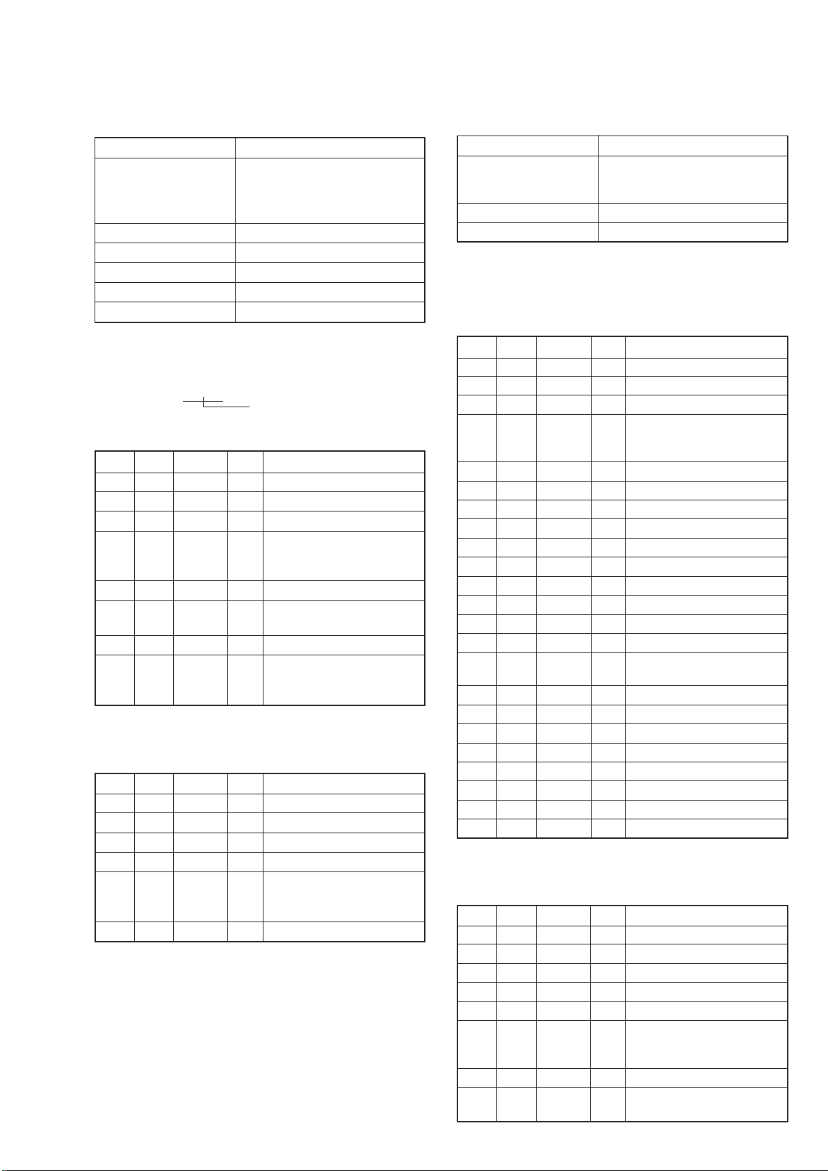
7. Light Level Adjustment
Adjust the standard LV value.
8. Auto White Balance Standard Data Input
Adjust the white balance standard data at 3200K.
Mode STILL
Subject Clear chart
(Color reproduction adjustment
frame with the zoom lens at WIDE
end)
Measurement Point Displayed data of page: 1 (Note 2)
Measuring Instrument Adjusting remote commander
Adjustment Page F
Adjustment Address 26, 28
Specified Value AE level 1: 0FE0 to 1020
Note 1: Check that the data of page: 6, address: 02 is “00”.
If not, turn the power of unit OFF/ON
Note 2: The right four digits of the page: 1 displayed data of the
adjusting remote commander.
XX:XX
1:
Displayed data
Adjusting method:
Order Page Address Data Procedure
1 0 01 01
25 F1FF
3 D 63 40 Press PAUSE button.
Perform “Data setting during
4 camera system adjustment”.
(Refer to page 5-13)
5 6 01 0D Press PAUSE button. (Note 3)
66 02
7 0 03 06
8 1 (Note 2) satisfies the AE level
Note 3: The adjustment data will be automatically input to page:
F, address: 26 and 28.
Processing after Completing Adjustment:
Order Page Address Data Procedure
1 0 03 00
2 6 01 00 Press PAUSE button.
35 F100
4 D 63 00 Press PAUSE button.
5 performed at step 4.
6 0 01 00
Check the data changes to
“01”.
Check that the displayed data
1 specified value.
Release the data setting
(Refer to page 5-13)
Mode STILL
Subject Clear chart
(Color reproduction adjustment
frame)
Adjustment Page F
Adjustment Address 3A to 3D, 59
Note 1: Check that the data of page: 6, address: 02 is “00”.
If not, turn the power of unit OFF/ON.
Note 2: Refer to “Picture Frame Setting” for XH, XL, YH and
YL.
Adjusting method:
Order Page Address Data Procedure
1 0 01 01
25 F1FF
3 D 63 40 Press PAUSE button.
Perform “Data setting during
4 camera system adjustment”.
(Refer to page 5-13)
5 6 90 00
6 6 91 04
7 6 92 00
8 6 93 30
96 6C01
10 6 2C 01
11 6 01 79 Press PAUSE button.
12 Wait for 3 seconds.
13 6 01 11 Press PAUSE button.
14 6 01 0B Press PAUSE button. (Note 3)
15 6 02
16 6 90 XL (Note 2)
17 6 91 XH (Note 2)
18 6 92 YL (Note 2)
19 6 93 YH (Note 2)
20 6 6C 01
21 6 2C 01
22 6 01 79 Press PAUSE button.
23 Wait for 3 seconds
Note 3: The adjustment data will be automatically input to page:
F, address: 3A to 3D and 59.
Processing after Completing Adjustment:
Order Page Address Data Procedure
1 6 01 00 Press PAUSE button.
26 6C00
36 2C00
45 F100
5 D 63 00 Press PAUSE button.
6 performed at step 4.
7 0 01 00
8
Check the data changes to
“01”.
Release the data setting
(Refer to page 5-13)
Perform “Auto White
Balance Adjustment”.
5-19
Page 77

9. Auto White Balance Adjustment
Adjust to the proper auto white balance output data.
If it is not correct, auto white balance and color reproducibility
will be poor.
Mode STILL
Subject Clear chart
(Color reproduction adjustment
frame)
Filter Filter C14 for color temperature
correction
Measurement Point Displayed data of page: 1 (Note 3)
Measuring Instrument Adjusting remote commander
Adjustment Page F
Adjustment Address 3F, 40, 80, A9, AA
Specified Value R ratio: 28E0 to 2A20
B ratio: 5C60 to 5DA0
Note 1: Perform “Auto White Balance Reference Data Input”
before this adjustment.
Note 2: Check that the data of page: 6, address: 02 is “00”.
If not, turn the power of unit OFF/ON.
Note 3: The right four digits of the page: 1 displayed data of the
adjusting remote commander.
1:XX:XX
Displayed data
Note 4: Refer to “Picture Frame Setting” for XH, XL, YH and
YL.
Adjusting method:
Order Page Address Data Procedure
1
2 0 01 01
35 F1FF
4 D 63 40 Press PAUSE button.
5 camera system adjustment”.
6 F 27 Note down the data.
7 F 27 80 Press PAUSE button.
8 6 90 00
9 6 91 04
10 6 92 00
11 6 93 30
12 6 6C 01
13 6 2C 01
14 6 01 79 Press PAUSE button.
15 Wait for 3 seconds.
16 6 01 A7 Press PAUSE button.
49
17 F
18 F
4A
4B
4C
49 29
4A 80
4B 5D
4C 00
Place the C14 filter on
the lens.
Perform “Data setting during
(Refer to page 5-13)
Note down the data.
Press PAUSE button.
19 6 01 A5 Press PAUSE button. (Note 5)
20 6 02
21 6 01 3F Press PAUSE button.
22 0 03 04
23 1 (Note 3) satisfied the R ratio
24 0 03 05
25 1 (Note 3) satisfied the B ratio
26 6 90 XL (Note 4)
27 6 91 XH (Note 4)
28 6 92 YL (Note 4)
29 6 93 YH (Note 4)
30 6 6C 01
31 6 2C 01
32 6 01 79 Press PAUSE button.
33 Wait for 3 seconds
34 6 01 11 Press PAUSE button.
35 6 13 88 Press PAUSE button.
36 6 01 D3 Press PAUSE button. (Note 5)
37 6 02 01
Note 5: The adjustment data will be automatically input to page:
F, address: 3F, 40, 80, A9 and AA.
Processing after Completing Adjustment:
Order Page Address Data Procedure
1 0 03 00
2 6 01 00 Press PAUSE button.
3F 27
49
4F
5 6 13 00 Press PAUSE button.
65 F100
7 D 63 00 Press PAUSE button.
8 performed at step 5.
9 0 01 00
4A Set data noted down at step 17,
4B and press PAUSE button.
4C
Check the data changes to
“01”.
Check that the displayed data
specified value.
Check that the displayed data
specified value.
Check the data changes to
“01”.
Set data noted down at step 6,
and press PAUSE button.
Release the data setting
(Refer to page 5-13)
5-20
Page 78

10.Smear Compensation Adjustment
Adjust the smear compensation data from white balance standard
data at 3200K.
11.Color Reproduction Adjustment
Adjust the color separation matrix coefficient so that proper color
reproduction is produced.
Mode STILL
Subject Clear chart
(Color reproduction adjustment
frame)
Adjustment Page F
Adjustment Address 9D, 9E
Note 1: Perform “Auto White Balance Standard Data Input” and
“ Auto White Balance Adjustment” before this adjustment.
Note 2: Check that the data of page: 6, address: 02 is “00”.
If not, turn the power of unit OFF/ON.
Adjusting method:
Order Page Address Data Procedure
1 0 01 01
25 F1FF
3 D 63 40 Press PAUSE button.
Perform “Data setting during
4 camera system adjustment”.
(Refer to page 5-13)
5 F 27 Note down the data.
6 F 27 80 Press PAUSE button.
7 6 01 11 Press PAUSE button.
8 6 13 88 Press PAUSE button.
9 6 01 D1 Press PAUSE button. (Note 3)
10 6 02
Note 3: The adjustment data will be automatically input to page:
F, address: 9D and 9E.
Processing after Completing Adjustment:
Order Page Address Data Procedure
1 6 01 00 Press PAUSE button.
2F 27
3 6 13 00 Press PAUSE button.
45 F100
5 D 63 00 Press PAUSE button.
6 performed at step 4.
7 0 01 00
Check the data changes to
“01”.
Set data noted down at step 5,
and press PAUSE button.
Release the data setting
(Refer to page 5-13)
Mode STILL
Subject Color bar chart
(Color reproduction adjustment
frame)
Adjustment Page F
Adjustment Address 41 to 48, 5C to 5F
Note 1: Perform “Auto White Balance Reference Data Input”
before this adjustment.
Note 2: Check that the data of page: 6, address: 02 is “00”.
If not, turn the power of unit OFF/ON.
Adjusting method:
Order Page Address Data Procedure
1 0 01 01
25 F1FF
3 D 63 40 Press PAUSE button.
Perform “Data setting during
4 camera system adjustment”.
(Refer to page 5-13)
5 6 01 AB Press PAUSE button.
6 6 01 A9 Press PAUSE button (Note 3)
76 02
Note 3: The adjustment data will be automatically input to page:
F, address: 41 to 48 and 5C to 5F.
Processing after Completing Adjustment:
Order Page Address Data Procedure
1 6 01 00 Press PAUSE button.
25 F100
3 D 63 00 Press PAUSE button.
4 performed at step 4.
5 0 01 00
6
Check the data changes to
“01”.
Release the data setting
(Refer to page 5-13)
Perform “Color Reproduction
Check”.
5-21
Page 79

12.Color Reproduction Check
Mode STILL
Subject Color bar chart
(Color reproduction adjustment
frame)
Measurement Point Video terminal of A/V OUT jack
(75 Ω terminated)
Measuring Instrument Vectorscope
Specified Value All color luminance points should
settle within each color reproduction
frame.
Menu setting:
1) VIDEO OUT of SET UP menu
........................................ NTSC (NTSC mode)
........................................ PAL (PAL mode)
Checking method:
Order Page Address Data Procedure
1 0 01 01
25 F1FF
3 D 63 40 Press PAUSE button.
Perform “Data setting during
4 camera system adjustment”.
(Refer to page 5-13)
5 6 10 01
6 E 52 Note down the data.
7 E 52 0A Press PAUSE button.
8 6 01 0F Press PAUSE button.
Check the each color luminance
9 point is in each color
reproduction frame.
Processing after Completing Adjustment:
Order Page Address Data Procedure
1 6 01 00 Press PAUSE button.
2 6 10 00
3E 52
Set data noted down at step 6,
and press PAUSE button.
45 F100
5 D 63 00 Press PAUSE button.
Release the data setting
6 performed at step 4.
(Refer to page 5-13)
7 0 01 00
For NTSC mode
Burst position
For PAL mode
Burst position
R-Y
M
R
Y
E
G
B-Y
B
C
Y
G
Fig. 5-1-17
R-Y
M
R
Y
E
G
B-Y
B
C
Y
G
Fig. 5-1-18
5-22
Page 80

R-Y
B-Y
4 mm
4 mm
13.Auto White Balance Check
Mode STILL
Subject Clear chart
(Color reproduction adjustment
frame)
Measurement Point Displayed data of Video terminal
of Page: 1 (Note 2) A/V OUT jack
(75 Ω terminated)
Measuring Instrument Adjustment remote V ectorscope
commander
Specified Value R ratio: Fig. 5-1-19
3E00 to 4200 (A) and (B)
B ratio:
3E00 to 4200
Note 1: Refer to “Picture Frame Setting” for XH, XL, YH and
YL.
Note 2: The right four digits of the page: 1 displayed data of the
adjusting remote commander.
1:XX:XX
Displayed data
Checking method:
Order Page Address Data Procedure
1
Check that the lens is not
covered with either filter.
2 0 01 01
35 F1FF
4 D 63 40 Press PAUSE button.
Perform “Data setting during
5 camera system adjustment”.
(Refer to page 5-13)
6 6 90 00
7 6 91 04
8 6 92 00
9 6 93 30
10 6 6C 01
11 6 2C 01
12 6 01 79 Press PAUSE button.
13 Wait for 3 seconds.
INDOOR data check
14 E 52 Note down the data.
15 E 52 1A Press PAUSE button.
16 6 01 0F Press PAUSE button.
17 0 03 04
Check that the displayed data
18 1 (Note 2) satisfied the R ratio
specified value.
19 0 03 05
Check that the displayed data
20 1 (Note 2) satisfied the B ratio
specified value.
INDOOR luminance point check
21 0 03 00
Check that the center of the
22 white luminance point within
the circle shown Fig 5-1-19 (A).
OUTDOOR luminance point check
23 Place the C14 filter on the lens.
24 E 4B Note down the data.
25 E 4B 20 Press PAUSE button.
26 6 01 3F Press PAUSE button.
Check that the center of the
27
white luminance point settles
in the circle shown Fig 5-1-19
(B).
28 6 90 XL (Note 1)
29 6 91 XH (Note 1)
30 6 92 YL (Note 1)
31 6 93 YH (Note 1)
32 6 6C 01
33 6 2C 01
34 6 01 79 Press PAUSE button.
35 Wait for 3 seconds.
Processing after Completing Adjustment:
Order Page Address Data Procedure
1 6 01 00 Press PAUSE button.
26 6C00
3E 4B
4E 52
Set data noted down at step 24,
and press PAUSE button.
Set data noted down at step 14,
and press PAUSE button.
56 2C00
65 F100
7 D 63 00 Press PAUSE button.
Release the data setting
8 performed at step 5.
(Refer to page 5-13)
9 0 01 00
Fig. 5-1-19 (A)
R-Y
1 mm
1.5 mm
6 mm
B-Y
6 mm
Fig. 5-1-19 (B)
5-23
Page 81

14.Strobe White Balance Adjustment
Adjust the white balance when the strobe light flashed.
Mode STILL
Subject Flash adjustment box (Note 3)
(1.0 m from the front of lens)
Adjustment Page F
Adjustment Address 4D, 4E, 64, 69, 6A, 6B
Specified Value Y level data: 64 to 98 (Note 4)
R-Y level data: FA to FF or 00 to 06
(Note 5)
B-Y level data: FA to FF or 00 to 06
(Note 5)
A/D integral value data: 0020 or
more (Note 6)
Note 1: Perform “Flange Back Adjustment”, “Light Level
Adjustment” and “Auto White Balance Adjustment”
before this adjustment.
Note 2: Perform this adjustment in the Flash adjustment box.
Note 3: Refer to “4. Preparing the Flash adjustment box”. (See
page 5-7)
Note 4: Displayed data of page: F, address: 64, of the adjusting
remote commander.
F:XX:64
Displayed data
Note 5: The right four digits of the page: 1 displayed data of the
adjusting remote commander.
1:XX:XX
R-Y level data
B-Y level data
Note 6: Displayed data of page: F, address: 69, 6A of the adjusting
remote commander.
F:XX:69
Displayed data
F:XX:6A
Displayed data
XX XX
Page: F, address: 6A (Lower)
Page: F, address: 69 (Higher)
Note 7: Check that the data of page: 6, address: 02 is “00”.
If not, turn the power of unit OFF/ON.
Switch setting:
1) FLASH ........................ ON
Checking method:
Order Page Address Data Procedure
1 0 01 01
25 F1FF
3 D 63 40 Press PAUSE button.
Perform “Data setting during
4 camera system adjustment”.
(Refer to page 5-13)
5 6 90 00
6 6 91 00
7 6 92 00
8 6 93 60
96 6C01
10 6 2C 01
11 6 01 79 Press PAUSE button.
12 7 01 44 Press PAUSE button.
13 Wait for 5 seconds.
Order Page Address Data Procedure
14 6 01 67 Press PAUSE button.
15 6 02
16 6 01 00 Press PAUSE button.
17 6 01 79 Press PAUSE button.
18 Wait for 1 second.
19 6 01 67 Press PAUSE button.
20 6 02
21 6 01 00 Press PAUSE button.
22 6 01 79 Press PAUSE button.
23 Wait for 1 second.
24 6 01 B9 Press PAUSE button. (Note 8)
25 6 02
26 6 01 00 Press PAUSE button.
27 6 01 79 Press PAUSE button.
28 Wait for 1 second.
29 6 01 67 PAUSE button.
30 6 02
31 F 64 (Note 4) satisfies the specified
32 0 03 02
33 1 data (Note 5) satisfies the
34 F
Note 8: The adjustment data will be automatically input to page:
F, address: 4D, 4E, 64 and 69 to 6B.
Processing after Completing Adjustment:
Order Page Address Data Procedure
16 2C00
2 6 93 00
3 6 01 00 Press PAUSE button.
46 6C00
5 7 01 04 Press PAUSE button.
6 0 03 00
75 F100
8 D 63 00 Press PAUSE button.
9 performed at step 4.
10 0 01 00
69
6A
Check the data changes to
“01”.
Check the data changes to
“01”.
Check the data changes to
“01”.
Check the data changes to
“01”.
Check that the Y level data
value.
Check that the R-Y, B-Y level
specified value.
Check that the A/D integral v alue
data (Note 6) satisfies the
specified value.
Release the data setting
(Refer to page 5-13)
5-24
Page 82

15.CCD Black Defect Compensation
16.CCD White Defect Compensation
Mode STILL
Subject Clear chart
Measurement Point Displayed data of page: 6,
Measuring Instrument Adjusting remote commander
Adjustment Page 7
Adjustment Address 60 to 87
Note 1: Check that there are no dust, no dirt and reflection of the
clear chart.
Note 2: Any subject other than the clear chart should be in the
screen.
Adjusting method:
Order Page Address Data Procedure
1 0 01 01
25 F1FF
3 D 63 40 Press PAUSE button.
4 camera system adjustment”.
5 F DF Note down the data.
6 F DF 4C Press PAUSE button.
76 2C01
8 6 90 00
9 6 91 04
10 6 92 00
11 6 93 00
12 6 6C 01
13 6 01 79 Press PAUSE button.
14 6 30 01
15 Wait for 2 seconds.
16 6 01 8D Press PAUSE button. (Note 3)
17 6 02
18 6 55 00 to 0A : Normal
19 6 01 00 Press PAUSE button.
20 F DF 5A Press PAUSE button.
21 6 01 89 Press PAUSE button.
22 6 02
23 6 55 00: Normal
Note 3: The adjustment data will be automatically input to page:
7, address: 60 to 87.
Processing after Completing Adjustment:
Order Page Address Data Procedure
1F DF
2 6 01 00 Press PAUSE button.
36 2C00
4 6 30 00
56 6C00
6 6 91 00
75 F100
8 D 63 00 Press PAUSE button.
9 performed at step 4.
10 0 01 00
(25 cm from the front of lens)
address: 55
Perform “Data setting during
(Refer to page 5-13)
Check the data changes to
“01”.
Check the data.
0B to FF : Defective
Check the data changes to
“01”.
Check the data.
01 to FF: Defective
Set data noted down at step 5,
and press PAUSE button.
Release the data setting
(Refer to page 5-13)
Mode STILL
Subject Clear chart
(25 cm from the front of lens)
Measurement Point Displayed data of page: 6,
address: 55
Measuring Instrument Adjusting remote commander
Adjustment Page 7
Adjustment Address 88 to A3
Note 1: Check that there are no dust, no dirt and reflection of the
clear chart.
Note 2: Any subject other than the clear chart should be in the
screen.
Adjusting method:
Order Page Address Data Procedure
1 0 01 01
25 F1FF
3 D 63 40 Press PAUSE button.
Perform “Data setting during
4 camera system adjustment”.
(Refer to page 5-13)
5 F DE Note down the data.
6 F DE 1E Press PAUSE button.
7 F E3 Note down the data.
8 F E3 0E Press PAUSE button.
9 6 01 8B Press PAUSE button. (Note 3)
10 6 02
11 6 55 00 to 7F: Normal
12 6 01 00 Press PAUSE button.
13 F DE 1E Press PAUSE button.
14 F E3 60 Press PAUSE button.
15 6 01 87 Press PAUSE button.
16 6 02
17 6 55 00: Normal
Note 3: The adjustment data will be automatically input to page:
7, address: 88 to A3.
Processing after Completing Adjustment:
Order Page Address Data Procedure
1F DE
2F E3
3 6 01 00 Press PAUSE button.
45 F100
5 D 63 00 Press PAUSE button.
6 performed at step 4.
7 0 01 00
Check the data changes to
“01”.
Check the data.
80 to FF: Defective
Check the data changes to
“01”.
Check the data.
01 to FF: Defective
Set data noted down at step 5,
and press PAUSE button.
Set data noted down at step 7,
and press PAUSE button.
Release the data setting
(Refer to page 5-13)
5-25
Page 83

1-5. LCD SYSTEM ADJUSTMENTS
Before perform the camera system adjustments, check that the
specified values of “VIDEO SYSTEM ADJUSTMENTS” are
satisfied.
Note 1: Taken an extreme care not to destroy the liquid crystal
display module by static electricity when replacing it.
Note 2: Set the LCD BRIGHT (Menu display) to the center.
[Adjusting connector]
Most of the measuring points for adjusting the LCD system are
concentrated in CN 881 of the PD-137 board.
Connect the Measuring Instruments via the CPC-9 jig (J-6082393-C).
The following table shows the Pin No. and signal name of CN
881.
Pin No. Signal Name Pin No. Signal Name
1 BL_L1 10 UNREG
2 BL_L2 11 LANC IN
3 N. C. 12 LANC OUT
4 REG_GND 13 MAKER_RECOG
5 N. C. 14 PF7
6 N. C. 15 TXD
7 HSY 16 RXD
8 PEARL_COM 17 RESET
9 VG 18 VDD
[LCD type check]
By measuring the resistor value between Pin qd of CN881 and
Pin 4 of CN881, the type LCD can be discriminated.
PD-137 board CN881
Resistor value LCD type
10 kΩ TYPE SA
22 kΩ TYPE ST
CPC-9 jig
(J-6082-393-C)
Volt ohm meter
qd pin
4 pin
18
1
CPC cover
1
18
Note 1: Don’t use the 12 pin flexible board of CPC-9 jig.
It causes damage to the unit.
Note 2: The old CPC-9 jig (Parts code: J-6082-393-B)
cannot be used, because it cannot operate
the adjustment remote commander.
PD-137 board
CN881
Fig. 5-1-20
5-26
Page 84

1. LCD Initial Data Input
Mode PLAY
Signal Arbitrary
Adjustment Page D
Adjustment Address D0 to DA , DC to DF
Adjusting method:
1) Select page: 0, address: 01, and set data: 01.
2) Select page: D, and enter the data given in the follo wing table.
Note: Press the PAUSE button each time the data are set, as the
data are written to non-volatile memory (EEPROM).
Address Data Remark
TYPE ST TYPE SA
D0 20 20 Bright Adjustment
D1 58 62 Color Adjustment
D2 A0 A0 White Blance Adjustment
D3 88 88
D4 D0 D0 Contrast Adjustment
D5 90 90 Black Limit Adjustment
D6 90 90 VG Center Adjustment
D7 60 70 VCO Adjustment (NTSC)
D8 90 98 V -COM Adjustment
D9 B3 B3 Fixed value
DA 7F 9A
DC B3 B3
DD 80 90 VCO Adjustment (PAL)
DE 43 43 Fixed value
DF 00 00
Processing after Completing Adjustments:
1) Select page: 0, address: 01, and set data: 00.
5-27
Page 85

2. VCO Adjustment (PD-137 Board)
Set the VCO free-run frequency. If deviated, the LCD screen will
be blurred.
Mode PLAY
Signal Arbitrary
Measurement Point CH1: Pin 7 of CN881
(HSY)
CH2: Video terminal of A/V
OUTjack
(75 Ω terminated)
Measuring Instrument Oscilloscope
Adjustment Page D
Adjustment Address D7 (NTSC)
DD (PAL)
Specified Value T = 2.04 ± 0.1 µs (TYPE ST)
T = 1.92 ± 0.1 µs (TYPE SA)
Menu setting:
1) VIDEO OUT of SET UP menu
..................................NTSC (NTSC mode)
(This adjustment must be performed in NTSC mode, so don’t
set the menu setting to “PAL” )
Adjusting method:
Order Page Address Data Procedure
1 0 01 01
Change the data and set the
2 D D7 phase difference (T) to the
specified value.
3 D D7 Press PAUSE button.
4D D7
Read the data and this data is
named D
D7
Conver DD7 to decimal
5 notation, and obtain DD7’
(Note)
Calculate D
’ using
DD
following equations (decimal
6 calculation)
DDD’ = DD7’ + 26 (TYPE ST)
DDD’ = DD7’ + 40 (TYPE SA)
Conver D
7 number, and obtain D
’ to a he xadecimal
DD
DD
(Note)
8DDDD
Press PAUSE button.
DD
Note: Refer to table 5-2-2. “Hexadecimal-decimal conversion
table”
CH1
CH2
H
magnified
CH1
CH2
T
T: Between the center of HSY signal rising and
VIDEO SYNC signal rising
Fig. 5-1-21
Processing after Completing Adjustments:
Order Page Address Data Procedure
1 0 01 00
5-28
Page 86

3. Black Limit Adjustment (PD-137 Board)
2H
Pedestal
Pedestal
A
A: Between the reversed waveform pedestal and non-reversed
waveform pedestal
Set the maximum amplitude of the RGB decoder for driving the
LCD to the specified value.
If deviated, the LCD screen image will be blackish or saturated
(whitish).
4. Bright Adjustment (PD-137 Board)
Set the amplitude of the RGB decoder for driving the LCD to the
specified value.
If deviated, the LCD screen image will be blackish or saturated
(whitish).
Mode PLAY
Signal Arbitrary
Measurement Point Pin 9 of CN881 (VG)
External trigger: Pin 8 of CN881
(PEARL COM)
Measuring Instrument Oscilloscope
Adjustment Page D
Adjustment Address D5
Specified Value A = 8.20 ± 0.1 Vp-p (TYPE ST)
A = 7.40 ± 0.1 Vp-p (TYPE SA)
Adjusting method:
Order Page Address Data Procedure
1 0 01 01
25 F103
3 D D0 Note down the data.
4 D D0 20 Press PAUSE button.
Change the data and set the
5 D D5 voltage (A) to the specified
value.
6 D D5 Press PAUSE button.
Processing after Completing Adjustments:
Order Page Address Data Procedure
15 F100
2D D0
Set data noted down at step 3,
and press PAUSE button.
3 0 01 00
Mode PLAY
Signal Arbitrary
Measurement Point Pin 9 of CN881 (VG)
External trigger: Pin 8 of CN881
(PEARL COM)
Measuring Instrument Oscilloscope
Adjustment Page D
Adjustment Address D0
Specified Value A = 7.96 ± 0.1 Vp-p (TYPE ST)
A = 7.00 ± 0.1 Vp-p (TYPE SA)
Adjusting method:
Order Page Address Data Procedure
1 0 01 01
25 F103
Change the data and set the
3 D D0 voltage (A) to the specified
value.
4 D D0 Press PAUSE button.
Processing after Completing Adjustments:
Order Page Address Data Procedure
15 F100
2 0 01 00
A
A: Between the reversed waveform peak and non-reversed
waveform peak
Fig. 5-1-22
2H
Fig. 5-1-23
5-29
Page 87

5. Contrast Adjustment (PD-137 Board)
Set the level of the VIDEO signal for driving the LCD to the
specified value.
If deviated, the LCD screen image will be blackish or saturated
(whitish).
Mode PLAY
Signal Arbitrary
Measurement Point Pin 9 of CN881 (VG)
External trigger: Pin 8 of CN881
(PEARL COM)
Measuring Instrument Oscilloscope
Adjustment Page D
Adjustment Address D4
Specified Value A = 2.50 ± 0.05 Vp-p (TYPE ST)
A = 2.24 ± 0.05 Vp-p (TYPE SA)
Adjusting method:
Order Page Address Data Procedure
1 0 01 01
25 F103
Change the data and set the
3 D D4 voltage (A) to the specified
value.
4 D D4 Press PAUSE button.
Processing after Completing Adjustments:
Order Page Address Data Procedure
15 F100
2 0 01 00
6. Color Adjustment (PD-137 Board)
Set the color saturation to the standard value.
If, deviated, the color will be dark or light.
Mode PLAY
Signal Arbitray
Measurement Point Pin 9 of CN881 (VG)
External trigger: Pin 8 of CN881
(PEARL COM)
Measuring Instrument Oscilloscope
Adjustment Page D
Adjustment Address D1
Specified Value A = 444 ± 50 mVp-p (TYPE ST)
A = 308 ± 50 mVp-p (TYPE SA)
Adjusting method:
Order Page Address Data Procedure
1 0 01 01
25 F104
Change the data and set the
2 D D1 voltage (A) to the specified
value.
4 D D1 Press PAUSE button.
Processing after Completing Adjustments:
Order Page Address Data Procedure
15 F100
2 0 01 00
10 steps peak
A
Pedestal
2H
A: Between the pedestal and 10 setps peak
Fig. 5-1-24
White 100%
Green
A
2H
A: Between the white 100% (Reference level) and green
Fig. 5-1-25
5-30
Page 88

7. VG Center Adjustment (PD-137 Board)
Set the center of VG signal for driving the LCD to the specified
value.
Mode PLAY
Signal Arbitrary
Measurement Point Pin 9 of CN881 (VG)
Measuring Instrument Digital voltmeter
Adjustment Page D
Adjustment Address D6
Specified Value A = 7.00 ± 0.05 V (TYPE ST)
A = 6.00 ± 0.05 V (TYPE SA)
Adjusting method:
Order Page Address Data Procedure
1 0 01 01
25 F102
Change the data and set the
3 D D6 DC voltage (A) to the specified
value.
4 D D6 Press PAUSE button.
Processing after Completing Adjustments:
Order Page Address Data Procedure
15 F100
2 0 01 00
8. V-COM Adjustment (PD-137 Board)
Set the DC bias of the common electrode drive signal of LCD to
the specified value.
If deviated, the LCD display will be move, producing flicker and
conspicuous vertical lines.
Mode PLAY
Signal Arbitrary
Measurement Point Check on LCD screen
Measuring Instrument
Adjustment Page D
Adjustment Address D8
Specified Value The brightness difference
between the section-A and
section-B is minimum
Note: Perform “Bright Adjustment” and “Contrast Adjusstment”
before this adjustment.
Adjusting method:
Order Page Address Data Procedure
1 0 01 01
25 F102
3 2 10 02
Change the data so that
4 D D8 brightness of the section A
and section B is equal.
TYPE SA:
Press PAUSE button, and
5D D8
proceed to “Processing after
Completing Adjustments”.
TYPE ST:
Proceed to step 6 to 11.
6D D8
Read the data and this data is
named Dref
Conver Dref to decimal
7 notation, and obtain Dref’
(Note)
Calculate D
’ using
D8
8 following equations
(decimal calculation)
9D
10 number, and obtain D
’ = Dref’ – 9
D8
Conver D
’ to a hexadecimal
D8
D8
(Note)
11 D D8 D
Press PAUSE button.
D8
Note: Refer to table 5-2-2. “Hexadecimal-decimal conversion
table”
Processing after Completing Adjustments:
Order Page Address Data Procedure
15 F100
2 2 10 00
3 0 01 00
B
A
B
A
A
B
A
B
Fig. 5-1-26
5-31
Page 89

9. White Blance Adjustment (PD-137 Board)
Correct the white balance.
If deviated, the LCD screen color cannot be reproduced.
Mode PLAY
Signal Arbitrary
Measurement Point Check on LCD screen
Measuring Instrument
Adjustment Page D
Adjustment Address D2, D3
Specified Value LCD screen must not be colored
Note 1: Check the white balance only when replacing the
following parts. If necessary, adjust them.
1. LCD panel
2. Light induction plate
3. IC801
Adjusting method:
Order Page Address Data Procedure
1 0 01 01
25 F102
3D
4
5 D LCD screen is not colored.
Note 2: To write in the non-volatile memory (EEPROM), press
the PAUSE button each time to set the data.
D2 A0 Press PAUSE button. (Initial
D3 88 value)
Check that the LCD screen is
not colored. If not colored,
proceed to “Processing after
Completing Adjustments”.
D2
D3
Change the data so that the
(Note 2)
Processing after Completing Adjustments:
Order Page Address Data Procedure
15 F100
2 0 01 00
5-32
Page 90

1-6. SYSTEM CONTROL SYSTEM ADJUSTMENTS
1. Battery Down Adjustment
Set the battery end voltage.
If the voltage is incorrect, the life of battery will shorten.
The image at the battery end will also be rough.
Mode STILL
Subject Arbitrary
Measurement Point Displayed data of page: 2,
address: 51
Measuring Instrument Adjusting remote commander
Adjustment Page D
Adjustment Address 90 to 94
Connection:
1) Connect the regulated power supply and the digital voltmeter
to the battery terminal as shown in Fig. 5-1-27.
Preparations before adjustment:
1) Adjust the output voltage of the regulated power supply so
that the digital voltmeter display is 3.6 ± 0.1 Vdc.
2) Turn off the power supply.
3) Turn the HOLD switch of the adjusting remote commander.
4) Turn on the power supply.
5) Insert the memory stick to the unit, and set the STILL mode.
6) Set the FOCUS switch in MANUAL mode.
Adjusting method:
Order Page Address Data Procedure
1 0 01 01
26 2C01
Decrease the output voltage
3
of the regulated power supply
so that digital voltmeter display
is 3.1 ± 0.01 Vdc.
Check the data.
4 2 51 74 to 86 : Normal
00 to 73, 87 to FF: Defective
52 51
Read the data, and this data
is named Dref.
6 D 90 Dref Press PAUSE button.
7
Convert Dref to decimal notati
on and obtain Dref’. (Note)
Calculate D91’, D92’, D93’
’ using following
and D
94
equations(decimal calculation)
8D
’=Dref’+3
91
’=Dref’+10
D
92
’=Dref’+10
D
93
D94’=Dref’+10
Convert D91’, D92’, D93’ and
’ to a he xadecimal number,
D
9
94
and obtain D
, D92, D93 and
91
D94 (Note)
10 D 91 D91Press PAUSE button.
11 D 92 D92Press PAUSE button.
12 D 93 D93Press PAUSE button.
13 D 94 D
Press PAUSE button.
94
Note: Refer to table 5-2-2. “Hexadecimal-decimal conversion
table”
CPC-9jig
(J-6082-393-C)
Adjusting remote
commander
18
1
Processing after Completing Adjustments:
Order Page Address Data Procedure
16 2C00
2 0 01 00
Regulated power supply
(3.1 ± 0.01 Vdc)
BT-2 board
CN001
CN001
qa pin
qd pin
1
18
Digital voltmeter
Regulated power supply
(6.0 to 7.2 Vdc)
PD-137 board
CN881
Fig. 5-1-27
5-33
Page 91

5-2. SERVICE MODE
2-1. ADJUSTING REMOTE COMMANDER
The adjusting remote commander is used for changing the calculation coefficient in signal processing, EVR data, etc. The adjusting remote commander performs bi-directional communication
with the unit using the remote commander signal line (LANC).
The resultant data of this bi-directional communication is written
in the non-volatile memory.
1. Used the Adjusting Remote Commander
1) Connect the adjusting remote commander to the CN881 on
the PD-137 board via CPC-9 jig (J-6082-393-C).
2) Adjust the HOLD switch of the adjusting remote commander
to “HOLD” (SERVICE position).
3) Turn on the power with the POWER switch of the unit.
If it has been properly connected, the LCD on the adjusting remote commander will display as shown in Fig. 5-2-1.
0 : 00 : 00
Page Data Address
• Changing the address
The address increases when the FF (M) button is pressed,
and decreases when the REW (M) button is pressed. There
are altogether 256 addresses, from 00 to FF.
• Changing the data (Data setting)
The data increases when the PLAY (N) button is pressed,
and decreases when the STOP (x) button is pressed. There
are altogether 256 data, from 00 to FF.
• Writing the adjustment data
The PAUSE button must be pressed to write the adjustment
data in the nonvolatile memory. (The new adjustment data
will not be recorded in the nonvolatile memory if this step is
not performed)
2. Precautions upon Using the Adjusting Remote
Commander
Mishandling of the adjusting remote commander may erase the
correct adjustment data at times. T o prev ent this, it is recommended
that all adjustment data be noted down before beginning adjustments and new adjustment data after each adjustment.
Fig. 5-2-1
4) Operate the adjusting remote commander as follows.
• Changing the page
The page increases when the EDIT SEARCH + button is
pressed, and decreases when the EDIT SEARCH – button is
pressed. There are altogether 16 pages, from 0 to F.
Hexadecimal
notation
LCD Display 01 23456789AbcdEF
Decimal notation
conversion value
0123456789ABCDEF
0123456789101112131415
Table 5-2-1
5-34
Page 92

2-2. DATA PROCESS
The calculation of the adjusting remote commander display data
(hexadecimal notation) are required for obtaining the adjustment
data of some adjustment items. In this case, after converting the
hexadecimal notation to decimal notation, calculate and convert
the result to hexadecimal notation, and use it as the adjustment
data. Table 5-2-2. indicates the hexadecimal notation- the decimal notation, calculation table.
Hexadecimal nontation-Decimal notation
The lower digits of the 0 1 2 3 4 56789ABCDEF
hexadecimal notation
The upper digits of the (A)(b)(c)(d)(E)(F)
hexadecimal notation
0 0123456789101112131415
1 16 17 18 19 20 21 22 23 24 25 26 27 28 29 30 31
2 32 33 34 35 36 37 38 39 40 41 42 43 44 45 46 47
3 48 49 50 51 52 53 54 55 56 57 58 59 60 61 62 63
4 64 65 66 67 68 69 70 71 72 73 74 75 76 77 78 79
5 80 81 82 83 84 85 86 87 88 89 90 91 92 93 94 95
6 96 97 98 99 100 101 102 103 104 105 106 107 108 109 110 111
7 112 113 114 115 116 117 118 119 120 121 122 123 124 125 126 127
8 128 129 130 131 132 133 134 135 136 137 138 139 140 141 142 143
9 144 145 146 147 148 149 150 151 152 153 154 155 156 157 158 159
A (A) 160 161 162 163 164 165 166 167 168 169 170 171 172 173 174 175
1→
B (b) 176 177 178 179 180 181 182 183 184 185 186 187 188 189 190 191
C (c) 192 193 194 195 196 197 198 199 200 201 202 203 204 205 206 207
D (d) 208 209 210 211 212 213 214 215 216 217 218 219 220 221 222 223
E (E) 224 225 226 227 228 229 230 231 232 233 234 235 236 237 238 239
F (F) 240 241 242 243 244 245 246 247 248 249 250 251 252 253 254 255
2
↓
Note : ( ) indicate the adjusting remote control unit display.
(Example) In the case that the adjusting remote control unit display are BD (bd).
As the upper digit of the hexadecimal notation is B (b), and the lower digit is D (d), the intersection “189” of
the1 and 2 in the above table is the decimal notation to be calculated.
Table 5-2-2
5-35
Page 93

2-3. SERVICE MODE
1. Setting the Test Mode
Page D Address 10
Data Function
00 Normal
01 Forced STILL mode power ON
02 Forced PLAY mode power ON
03 Forced MOVIE mode power ON
• Before setting the data, select page: 0, address: 01, and set data:
01.
• For page D, the data set is recorded in the non-volatile memory
by pressing the PAUSE button of the adjusting remote commander. In this case, take note that the test mode will not be
exited even when the main power is turned off.
• After completing adjustments/repairs, be sure to return the data
of this address to “00”, and press the PAUSE button of the adjusting remote commander.
Select page: 0, address: 01, and set data: 00.
2. Bit Value Discrimination
Bit values must be discriminated using the display data of the adjusting remote commander for following items. Use the table below to discriminate if the bit value is “1” or “0”
3. Switch Check (1)
Page 2 Address 43
Bit Function
SHUTTER SW
2
(PW-122 board)
XSHUTTER LOCK SW
3
(PW-122 board)
Using method:
1) Select page: 2, address: 43
2) By discriminating the bit value of dispaly data, the state of the
switches can be discriminated.
When bit value=1 When bit value=0
OFF ON
OFF ON
Display on the adjustilng remote commander
0 : 00 : 00
Page
Display on the Bit values
Adjusting bit3 bit2 bit1 bit0
remote or or or or
commander bit7 bit6 bit5 bit4
00000
10001
20010
30011
40100
50101
60110
70111
A
B
Example: If “8E” is displayed on the adjusting remote com-
81000
91001
A(A)1010
B(b)1011
C(c)1100
D(d)1101
E(E)1110
F(F)1111
mander, the bit values for bit7 to bit4 ar e shown in the
A column, and the bit values for bit3 to bit0 are shown
in the B column.
bit3 to bit0 discrimination
bit7 to bit4 discrimination
Address
5-36
Page 94

4. Switch Check (2)
Page 2 Addresses 55 to 57
Using method:
1) Select page: 2, addresses: 55 to 57.
2) By discriminating the dispaly data, the pressed key can be
discriminated.
Address
55
(KEY AD1) (PD-137 board) (PD-137 board) (PD-137 board) (SW-349 board) (SW-349 board)
(IC404 ul) (S882) (S882) (S881) (S005) (S007)
56
(KEY AD2) (PD-137 board) (PD-137 board) (PD-137 board) (SW-349 board) (SW-349 board) (SW-349 board)
(IC404 i;) (S882) (S882) (S882) (S002) (S003) (S006)
57
(KEY AD3) (SW-349 board)
(IC404 ia) (S008)
5. LED, LCD Check
Page 2 Address 06 Data 02
Using method:
1) Select page: 2, address: 06, and set data: 02.
2) Check that all LED except for the A CCESS LED are lit and all
segments of LCD (display window) are lit.
3) Select page: 2, address: 06, and set data: 00.
00 to 14 15 to 3B 3C to 64 65 to 91 92 to BD BE to E9 EA to FF
CONTROL DOWN CONTROL UP DISPLAY VOLUME+ VOLUME–
CONTROL RIGHT CONTROL LEFT
CONTROL SET FLASH MACRO
Data
LCD BACK LIGHT OFF
PROGRAM AE
5-375-37 E
Page 95

SECTION 6
REPAIR PARTS LIST
DSC-P1
6-1. EXPLODED VIEWS
NOTE:
• -XX and -X mean standardized parts, so they may
have some difference from the original one.
• Color Indication of Appearance Parts
Example:
KNOB, BALANCE (WHITE) . . . (RED)
↑↑
Parts Color Cabinet's Color
6-1-1. UPPER CABINET SECTION
17
18
19
not
supplied
SW151
8
7
• Items marked “*” are not stocked since they are
seldom required for routine service. Some delay
should be anticipated when ordering these items.
• The mechanical parts with no reference number in
the exploded views are not supplied.
• Accessories are given in the last of the electrical
parts list.
16
12
not supplied
13
11
14
15
9
7
6
MIC901
The components identified by mark
0 or dotted line with mark 0 are
critical for safety.
Replace only with part number specified.
Les composants identifiés par une
marque 0 sont critiquens pour la
sécurité.
Ne les remplacer que par une pièce
portant le numéro spécifié.
Rear cabinet section (See page 6-2.)
2
20
5
10
7
Main section
(See page 6-3.)
1
3
4
2
Ref. No. Part No. Description Remark Ref. No. Part No. Description Remark
1 X-3951-025-1 CABINET (FRONT) ASSY
2 3-989-735-81 SCREW (M1.7), LOCK ACE, P2
3 3-064-242-01 CABINET (BOTTOM)
4 3-969-387-01 FOOT, RUBBER
* 5 3-064-227-01 SHEET, MICROPHONE
12 3-064-263-01 BUTTON, SHUTTER
13 3-064-260-01 KNOB, POWER
14 3-064-237-01 SPRING, COMPRESSION
15 3-064-266-01 SLIDER (POWER)
16 3-064-259-01 KNOB, MODE
* 6 3-065-229-01 SHEET (UPPER)
7 3-989-735-51 SCREW (M1.7), LOCK ACE, P2
8 A-7096-377-A PW-122 BLOCK ASSY
* 9 3-055-971-01 CUSHION, MICROPHONE
10 3-318-382-03 SCREW (1.7), TAPPING
11 X-3951-027-1 CABINET (UPPER) ASSY
17 X-3946-488-1 SPRING ASSY, AE LEAF
18 3-064-496-01 DISK (MODE)
19 3-318-382-21 SCREW (1.7X3), TAPPING
* 20 3-066-383-01 SHEET, FLEXIBLE FIXED
MIC901 1-542-446-11 MICROPHONE
* SW151 X-3951-075-1 SLIDER (MODE) ASSY
6-1
Page 96

6-1-2. REAR PANEL SECTION
63
51
51
52
51
54
71
55
51
56
57
72
D9001
not supplied
62
58
LCD901
59
60
72
61
66
65
64
67
68
69
53
51
70
(Note) About PD-137 board and LCD module, discrimi-
nate LCD type on the machine referring to page
6, and replace the same type.
Ref. No. Part No. Description Remark Ref. No. Part No. Description Remark
51 3-318-382-03 SCREW (1.7), TAPPING
52 A-7096-373-A PD-137 BLOCK ASSY (TYPE ST)
52 A-7096-374-A PD-137 BLOCK ASSY (TYPE SA)
53 A-7096-375-A SW-349 BLOCK ASSY
* 54 3-064-278-01 SHEET METAL, ZM
55 A-7074-603-A ZM-26 BOARD, COMPLETE
* 56 3-703-357-02 PIN, PARALLEL (DIA. 1.6X5)
57 X-3951-031-1 CABINET (REAR) ASSY, INNER (SERVICE)
58 3-064-281-01 COVER, JACK
59 3-055-366-01 MARK, MS
60 3-065-177-01 SCREW (1.7X3)
61 3-064-225-01 LID, CPC
62 7-624-118-01 RING, RETAINING E-2.5
63 X-3951-032-1 CABINET (REAR) ASSY, ALUMINUM (SERVICE)
64 3-064-248-01 HOLDER, F BUTTON
* 65 3-064-250-01 SPRING, F BUTTON
66 3-064-247-01 BUTTON, FUNCTION
67 3-064-274-01 COVER, LCD
68 3-064-230-01 SHEET (P), ADHESIVE
* 69 3-064-233-01 SHEET (B), INSULATING
* 70 3-065-667-01 SHEET (SW), INSULATING
* 71 3-065-230-01 SHEET (F), LIGHT INTERCEPTION
72 3-064-219-01 ADHESIVE SHEET (A)
D9001 1-476-330-11 BLOCK, LIGHT GUIDE PLATE (TYPE ST)
D9001 1-476-331-21 BLOCK, LIGHT GUIDE PLATE (TYPE SA)
LCD901 1-804-206-21 INDICATOR MODULE, LIQUID CRYSTAL
(TYPE SA)
LCD901 8-753-050-66 ACX309AK-1 (TYPE ST)
6-2
Page 97

6-1-3. MAIN SECTION
111
not
supplied
not
supplied
115
116
114
(Note 2)
111
121
112
120
111
106
106
117
106
106
106
122
109
110
108
108
123
107
106
105
104
IC151
(Note 1)
102
118
103
101
$
!
: BT001 (BATTERY, LITHIUM SECONDARY)
Board on the mount position. (See page 4-73.)
113
119
A
A
The components identified by
mark 0 or dotted line with
mark 0 are critical for safety .
Replace only with part number specified.
Ref. No. Part No. Description Remark Ref. No. Part No. Description Remark
* 107 3-064-244-01 FRAME, LENS
0 112 A-7074-599-A ST-62 BOARD, COMPLETE
101 1-758-517-11 LENS, VIDEO (98WA)
102 1-758-516-11 FILTER BLOCK, OPTICAL
103 3-054-555-01 RUBBER (K), SEAL
104 A-7074-592-A CD-290 BOARD, COMPLETE
105 3-713-791-41 SCREW (M1.7X5), TAPPING, P2
106 3-989-735-51 SCREW (M1.7), LOCK ACE, P2
108 3-064-217-01 CUSHION, FRAME
109 3-064-216-01 CUSHION (L)
110 3-064-215-01 SCREW (M1.7), STEP
111 3-318-382-03 SCREW (1.7), TAPPING
113 X-3951-028-1 HOLDER ASSY, BT
Les composants identifiés par une
marque 0 sont critiques pour la
sécurité.
Ne les remplacer que par une pièce
portant le numéro spécifié.
(Note 1) Be sure to read “Precuations for Replacement
(Note 2) Be sure to read “2-1. BT LID ASSEMBLY
of CCD Imager” on page 4-8 when changing
the CCD imager.
REPLACING METHOD” on page 2-2 when
changing the BT lid assy.
114 X-3951-282-1 BT LID ASSY (SERVICE) (Note 2)
115 3-064-207-01 CLAW, BT LOCK
116 3-064-208-01 SPRING, BT LOCK
117 A-7074-605-A MT-60 BOARD, COMPLETE (SERVICE)
118 3-065-690-01 PLATE, LIGHT INTERCEPTION
* 119 3-066-692-01 SHEET, INSULATING
120 1-679-962-11 FP-338 FLEXIBLE BOARD
121 3-064-238-01 SHEET (C), INSULATING
122 3-064-232-01 SHEET (A), INSULATING
* 123 3-065-666-01 SHEET (LF), INSUALTING
IC151 A-7031-134-A CCD BLOCK ASSY (CCD IMAGER) (Note 1)
6-3
(BT-2, CA-66, DD-150, HI-74 and PS-440 boards
are included in this complete board)
Page 98

CD-290 MT-60
6-2. ELECTRICAL PARTS LIST
NOTE:
• Due to standardization, replacements in the
parts list may be different from the parts specified in the diagrams or the components used
on the set.
• -XX and -X mean standardized parts, so they
may have some difference from the original
one.
• RESISTORS
All resistors are in ohms.
METAL: Metal-film resistor.
METAL OXIDE: Metal oxide-film resistor.
F: nonflammable
• Abbreviation
AUS : Australian model
CN : Chinese model
CND: Canadian model
HK : Hong Kong model
Ref. No. Part No. Description Remark Ref. No. Part No. Description Remark
A-7074-592-A CD-290 BOARD, COMPLETE
(Ref. No.: 20,000 Series)
(IC151 is not included in this complete board)
J : Japanese model
JE : Tourist model
KR : Korea model
************************
• Items marked “*” are not stocked since they
are seldom required for routine service.
Some delay should be anticipated when ordering these items.
• SEMICONDUCTORS
In each case, u: µ, for example:
uA. . : µA. . uPA. . : µPA. .
uPB. . : µPB. . uPC. . : µPC. .
uPD. . : µPD. .
• CAPACITORS
uF: µF
• COILS
uH: µH
About PD-137 board and LCD module, discriminate LCD type on the machine referring
to page 6, and replace the same type.
The components identified by
mark 0 or dotted line with mark
0 are critical for safety.
Replace only with part number
specified.
Les composants identifiés par une
marque 0 sont critiquens pour la
sécurité.
Ne les remplacer que par une pièce
portant le numéro spécifié.
When indicating parts by reference
number, please include the board.
< CAPACITOR >
C152 1-162-966-11 CERAMIC CHIP 0.0022uF 10% 50V
C153 1-107-826-11 CERAMIC CHIP 0.1uF 10% 16V
C154 1-107-826-11 CERAMIC CHIP 0.1uF 10% 16V
C155 1-107-826-11 CERAMIC CHIP 0.1uF 10% 16V
C156 1-107-826-11 CERAMIC CHIP 0.1uF 10% 16V
C157 1-162-915-11 CERAMIC CHIP 10PF 0.5PF 50V
< IC >
IC151 A-7031-134-A CCD BLOCK ASSY
< TRANSISTOR >
Q151 8-729-037-74 TRANSISTOR UN9213J- (K8).SO
Q152 8-729-050-22 TRANSISTOR 2SC4250 (T5LSONY1)
< RESISTOR >
R153 1-216-826-11 METAL CHIP 2.7K 5% 1/16W
R154 1-216-805-11 METAL CHIP 47 5% 1/16W
R155 1-216-857-11 METAL CHIP 1M 5% 1/16W
R156 1-216-827-11 METAL CHIP 3.3K 5% 1/16W
R157 1-216-864-11 METAL CHIP 0 5% 1/16W
R158 1-216-814-11 METAL CHIP 270 5% 1/16W
A-7074-605-A MT-60 BOARD, COMPLETE (SERVICE)
********************************
(Ref. No.: 10,000 Series)
(BT-2, CA-66, DD-150, HI-74 and PS-440 boards are included in this
complete board)
Electrical parts list of the BT-2, CA-66, DD150, HI-74, MT-60 and PS-440 board are not
shown.
Pages 6-5 to 6-11 are not shown.
(Note) Be sure to read “Note on the CCD Imager
Replacement” on page 4-8 when changing the
CCD imager.
6-4
Page 99

PD-137 (TYPE SA)
Ref. No. Part No. Description Remark Ref. No. Part No. Description Remark
A-7096-374-A PD-137 BLOCK ASSY (TYPE SA)
***************************
(Ref. No.: 10,000 Series)
< CAPACITOR >
C801 1-137-702-91 TANTALUM CHIP 1.5uF 20% 20V
C802 1-164-943-11 CERAMIC CHIP 0.01uF 10% 16V
C803 1-137-700-91 TANTALUM CHIP 10uF 20% 6.3V
C804 1-125-777-11 CERAMIC CHIP 0.1uF 10% 10V
C805 1-125-777-11 CERAMIC CHIP 0.1uF 10% 10V
C806 1-125-838-11 CERAMIC CHIP 2.2uF 10% 6.3V
C807 1-164-943-11 CERAMIC CHIP 0.01uF 10% 16V
C808 1-164-943-11 CERAMIC CHIP 0.01uF 10% 16V
C809 1-164-943-11 CERAMIC CHIP 0.01uF 10% 16V
C810 1-125-777-11 CERAMIC CHIP 0.1uF 10% 10V
Q801 8-729-050-76 TRANSISTOR EC3201C-PM-TL
Q802 8-729-050-74 TRANSISTOR 2SB1462L0AS0
Q803 8-729-050-74 TRANSISTOR 2SB1462L0AS0
Q804 8-729-050-74 TRANSISTOR 2SB1462L0AS0
Q805 8-729-050-76 TRANSISTOR EC3201C-PM-TL
Q806 8-729-050-76 TRANSISTOR EC3201C-PM-TL
Q807 8-729-050-91 TRANSISTOR UNRL21300AS0
Q809 8-729-050-91 TRANSISTOR UNRL21300AS0
Q812 8-729-050-76 TRANSISTOR EC3201C-PM-TL
Q813 8-729-050-74 TRANSISTOR 2SB1462L0AS0
Q814 8-729-050-76 TRANSISTOR EC3201C-PM-TL
< TRANSISTOR >
< RESISTOR >
C811 1-127-760-11 CERAMIC CHIP 4.7uF 10% 6.3V
C812 1-127-760-11 CERAMIC CHIP 4.7uF 10% 6.3V
C813 1-127-760-11 CERAMIC CHIP 4.7uF 10% 6.3V
C814 1-125-777-11 CERAMIC CHIP 0.1uF 10% 10V
C815 1-164-505-11 CERAMIC CHIP 2.2uF 16V
C816 1-164-505-11 CERAMIC CHIP 2.2uF 16V
C817 1-107-686-11 TANTALUM CHIP 4.7uF 20% 16V
C818 1-137-700-91 TANTALUM CHIP 10uF 20% 6.3V
C820 1-125-777-11 CERAMIC CHIP 0.1uF 10% 10V
C821 1-107-826-11 CERAMIC CHIP 0.1uF 10% 16V
C822 1-125-777-11 CERAMIC CHIP 0.1uF 10% 10V
C823 1-125-777-11 CERAMIC CHIP 0.1uF 10% 10V
C824 1-164-943-11 CERAMIC CHIP 0.01uF 10% 16V
C825 1-127-760-11 CERAMIC CHIP 4.7uF 10% 6.3V
C826 1-164-940-11 CERAMIC CHIP 0.0033uF 10% 16V
C827 1-164-868-11 CERAMIC CHIP 56PF 5% 16V
C828 1-125-777-11 CERAMIC CHIP 0.1uF 10% 10V
C829 1-164-937-11 CERAMIC CHIP 0.001uF 10% 16V
C832 1-107-823-11 CERAMIC CHIP 0.47uF 10% 16V
< CONNECTOR >
CN805 1-794-770-21 CONNECTOR, FFC/FPC (LIF) 24P
CN806 1-794-766-21 CONNECTOR, FFC/FPC (LIF) 6P
CN881 1-794-769-21 CONNECTOR, FFC/FPC (LIF) 18P
CN882 1-794-768-21 CONNECTOR, FFC/FPC (LIF) 11P
CN883 1-778-804-11 CONNECTOR, BOARD TO BOARD 40P
CN884 1-794-411-21 CONNECTOR, FFC/FPC (LIF) 8P
< DIODE >
D802 8-713-102-80 DIODE 1T369-01-T8A
D880 8-719-062-16 DIODE 01ZA8.2 (TPL3)
< IC >
IC801 8-759-524-98 IC CXA8116R-T4
IC802 8-759-364-05 IC MB40D001PFV-G-BND-ER
IC803 8-759-337-40 IC NJM2904V (TE2)
IC804 8-759-677-84 IC LC12017-52T-TE-B
< COIL >
L801 1-469-757-21 INDUCTOR 10uH
L802 1-469-528-91 INDUCTOR 100uH
L803 1-469-757-21 INDUCTOR 10uH
L804 1-412-949-21 INDUCTOR 6.8uH
L805 1-469-757-21 INDUCTOR 10uH
R801 1-218-970-11 RES-CHIP 27K 5% 1/16W
R802 1-218-969-11 RES-CHIP 22K 5% 1/16W
R803 1-218-965-11 RES-CHIP 10K 5% 1/16W
R804 1-218-941-11 RES-CHIP 100 5% 1/16W
R805 1-218-941-11 RES-CHIP 100 5% 1/16W
R806 1-218-941-11 RES-CHIP 100 5% 1/16W
R807 1-218-941-11 RES-CHIP 100 5% 1/16W
R808 1-218-969-11 RES-CHIP 22K 5% 1/16W
R809 1-218-977-11 RES-CHIP 100K 5% 1/16W
R810 1-218-961-11 RES-CHIP 4.7K 5% 1/16W
R811 1-218-971-11 RES-CHIP 33K 5% 1/16W
R812 1-218-973-11 RES-CHIP 47K 5% 1/16W
R813 1-218-971-11 RES-CHIP 33K 5% 1/16W
R814 1-218-973-11 RES-CHIP 47K 5% 1/16W
R815 1-218-969-11 RES-CHIP 22K 5% 1/16W
R816 1-218-971-11 RES-CHIP 33K 5% 1/16W
R817 1-218-972-11 RES-CHIP 39K 5% 1/16W
R818 1-218-973-11 RES-CHIP 47K 5% 1/16W
R821 1-218-965-11 RES-CHIP 10K 5% 1/16W
R822 1-218-961-11 RES-CHIP 4.7K 5% 1/16W
R823 1-218-973-11 RES-CHIP 47K 5% 1/16W
R824 1-218-973-11 RES-CHIP 47K 5% 1/16W
R825 1-218-990-11 SHORT 0
R826 1-218-977-11 RES-CHIP 100K 5% 1/16W
R827 1-218-965-11 RES-CHIP 10K 5% 1/16W
R828 1-218-941-11 RES-CHIP 100 5% 1/16W
R829 1-218-941-11 RES-CHIP 100 5% 1/16W
R830 1-218-941-11 RES-CHIP 100 5% 1/16W
R832 1-218-989-11 RES-CHIP 1M 5% 1/16W
R833 1-218-975-11 RES-CHIP 68K 5% 1/16W
R834 1-218-972-11 RES-CHIP 39K 5% 1/16W
R835 1-218-965-11 RES-CHIP 10K 5% 1/16W
R836 1-218-981-11 RES-CHIP 220K 5% 1/16W
R837 1-218-969-11 RES-CHIP 22K 5% 1/16W
R840 1-218-990-11 SHORT 0
R841 1-218-971-11 RES-CHIP 33K 5% 1/16W
R842 1-218-977-11 RES-CHIP 100K 5% 1/16W
R843 1-218-974-11 RES-CHIP 56K 5% 1/16W
R845 1-218-981-11 RES-CHIP 220K 5% 1/16W
R846 1-218-970-11 RES-CHIP 27K 5% 1/16W
R847 1-218-973-11 RES-CHIP 47K 5% 1/16W
R848 1-218-975-11 RES-CHIP 68K 5% 1/16W
R849 1-218-965-11 RES-CHIP 10K 5% 1/16W
R851 1-218-965-11 RES-CHIP 10K 5% 1/16W
R854 1-218-971-11 RES-CHIP 33K 5% 1/16W
6-12
Page 100

PD-137 (TYPE SA) PD-137 (TYPE ST)
Ref. No. Part No. Description Remark Ref. No. Part No. Description Remark
R855 1-218-953-11 RES-CHIP 1K 5% 1/16W
R856 1-218-990-11 SHORT 0
R857 1-218-990-11 SHORT 0
R859 1-218-990-11 SHORT 0
R860 1-469-082-21 FERRITE 600uH (Note)
C822 1-125-777-11 CERAMIC CHIP 0.1uF 10% 10V
C823 1-125-777-11 CERAMIC CHIP 0.1uF 10% 10V
C824 1-164-943-11 CERAMIC CHIP 0.01uF 10% 16V
C825 1-127-760-11 CERAMIC CHIP 4.7uF 10% 6.3V
C826 1-164-940-11 CERAMIC CHIP 0.0033uF 10% 16V
R861 1-218-975-11 RES-CHIP 68K 5% 1/16W
R862 1-218-977-11 RES-CHIP 100K 5% 1/16W
R863 1-216-864-11 METAL CHIP 0 5% 1/16W
R864 1-216-864-11 METAL CHIP 0 5% 1/16W
R865 1-216-864-11 METAL CHIP 0 5% 1/16W
R868 1-218-964-11 RES-CHIP 8.2K 5% 1/16W
R869 1-218-953-11 RES-CHIP 1K 5% 1/16W
R871 1-211-989-11 METAL CHIP 68 0.5% 1/16W
R872 1-218-990-11 SHORT 0
R873 1-218-990-11 SHORT 0
R874 1-218-990-11 SHORT 0
R875 1-218-990-11 SHORT 0
R876 1-218-990-11 SHORT 0
R877 1-211-989-11 METAL CHIP 68 0.5% 1/16W
R878 1-218-964-11 RES-CHIP 8.2K 5% 1/16W
R882 1-218-990-11 SHORT 0
R888 1-469-082-21 FERRITE 600uH (Note)
R889 1-469-082-21 FERRITE 600uH (Note)
R890 1-218-956-11 RES-CHIP 1.8K 5% 1/16W
R891 1-218-956-11 RES-CHIP 1.8K 5% 1/16W
R892 1-218-958-11 RES-CHIP 2.7K 5% 1/16W
R893 1-218-958-11 RES-CHIP 2.7K 5% 1/16W
< SWITCH >
S881 1-771-138-61 SWITCH, KEY BOARD (DISPLAY)
S882 1-786-039-21 SWITCH, TACTILE (CONTROL)
C827 1-164-868-11 CERAMIC CHIP 56PF 5% 16V
C828 1-125-777-11 CERAMIC CHIP 0.1uF 10% 10V
C829 1-164-937-11 CERAMIC CHIP 0.001uF 10% 16V
C830 1-109-982-11 CERAMIC CHIP 1uF 10% 10V
C831 1-110-501-11 CERAMIC CHIP 0.33uF 10% 16V
C832 1-107-823-11 CERAMIC CHIP 0.47uF 10% 16V
< CONNECTOR >
CN805 1-794-770-21 CONNECTOR, FFC/FPC (LIF) 24P
CN806 1-794-766-21 CONNECTOR, FFC/FPC (LIF) 6P
CN881 1-794-769-21 CONNECTOR, FFC/FPC (LIF) 18P
CN882 1-794-768-21 CONNECTOR, FFC/FPC (LIF) 11P
CN883 1-778-804-11 CONNECTOR, BOARD TO BOARD 40P
CN884 1-794-411-21 CONNECTOR, FFC/FPC (LIF) 8P
< DIODE >
D802 8-713-102-80 DIODE 1T369-01-T8A
D803 8-719-050-42 DIODE RD3.3UM-T1B
D880 8-719-062-16 DIODE 01ZA8.2 (TPL3)
< IC >
IC801 8-759-524-98 IC CXA8116R-T4
IC802 8-759-364-05 IC MB40D001PFV-G-BND-ER
IC803 8-759-337-40 IC NJM2904V (TE2)
IC804 8-752-405-01 IC CXD3510R-T4
< COIL >
A-7096-373-A PD-137 BLOCK ASSY (TYPE ST)
**************************
(Ref. No.: 10,000 Series)
< CAPACITOR >
C801 1-137-702-91 TANTALUM CHIP 1.5uF 20% 20V
C802 1-164-943-11 CERAMIC CHIP 0.01uF 10% 16V
C803 1-137-700-91 TANTALUM CHIP 10uF 20% 6.3V
C804 1-125-777-11 CERAMIC CHIP 0.1uF 10% 10V
C805 1-125-777-11 CERAMIC CHIP 0.1uF 10% 10V
C806 1-125-838-11 CERAMIC CHIP 2.2uF 10% 6.3V
C807 1-164-943-11 CERAMIC CHIP 0.01uF 10% 16V
C808 1-164-943-11 CERAMIC CHIP 0.01uF 10% 16V
C809 1-164-943-11 CERAMIC CHIP 0.01uF 10% 16V
C810 1-125-777-11 CERAMIC CHIP 0.1uF 10% 10V
C811 1-127-760-11 CERAMIC CHIP 4.7uF 10% 6.3V
C812 1-127-760-11 CERAMIC CHIP 4.7uF 10% 6.3V
C813 1-127-760-11 CERAMIC CHIP 4.7uF 10% 6.3V
C814 1-125-777-11 CERAMIC CHIP 0.1uF 10% 10V
C815 1-164-505-11 CERAMIC CHIP 2.2uF 16V
C816 1-164-505-11 CERAMIC CHIP 2.2uF 16V
C817 1-107-686-11 TANTALUM CHIP 4.7uF 20% 16V
C818 1-137-700-91 TANTALUM CHIP 10uF 20% 6.3V
C820 1-125-777-11 CERAMIC CHIP 0.1uF 10% 10V
C821 1-107-826-11 CERAMIC CHIP 0.1uF 10% 16V
L801 1-469-757-21 INDUCTOR 10uH
L802 1-469-528-91 INDUCTOR 100uH
L803 1-469-757-21 INDUCTOR 10uH
L804 1-412-949-21 INDUCTOR 6.8uH
L805 1-469-757-21 INDUCTOR 10uH
< TRANSISTOR >
Q801 8-729-050-76 TRANSISTOR EC3201C-PM-TL
Q802 8-729-050-74 TRANSISTOR 2SB1462L0AS0
Q803 8-729-050-74 TRANSISTOR 2SB1462L0AS0
Q804 8-729-050-74 TRANSISTOR 2SB1462L0AS0
Q805 8-729-050-76 TRANSISTOR EC3201C-PM-TL
Q806 8-729-050-76 TRANSISTOR EC3201C-PM-TL
Q811 8-729-037-53 TRANSISTOR 2SA1832F-Y/GR (TPL3)
Q812 8-729-050-76 TRANSISTOR EC3201C-PM-TL
Q813 8-729-050-74 TRANSISTOR 2SB1462L0AS0
Q814 8-729-050-76 TRANSISTOR EC3201C-PM-TL
< RESISTOR >
R801 1-218-970-11 RES-CHIP 27K 5% 1/16W
R802 1-218-969-11 RES-CHIP 22K 5% 1/16W
R803 1-218-965-11 RES-CHIP 10K 5% 1/16W
R804 1-218-941-11 RES-CHIP 100 5% 1/16W
R805 1-218-941-11 RES-CHIP 100 5% 1/16W
R806 1-218-941-11 RES-CHIP 100 5% 1/16W
R807 1-218-941-11 RES-CHIP 100 5% 1/16W
6-13
Note: Ferrite beads are mounted to the location
where R860, R888 and R889 are printed.
 Loading...