

Sony DR-GA500 Operating manual
Digital Surround
Headset System
4-194-154-52(1)
DR-GA500
©2010 Sony Corporation
Operating Instructions
Mode d’emploi
Manual de instrucciones
US
FR
ES

2
US
WARNING
To reduce the risk of fire or electric
shock, do not expose this apparatus to
rain or moisture.
To reduce the risk of fire or electric shock, do not
expose this apparatus to dripping or splashing, and
do not place objects filled with liquids, such as
vases, on the apparatus.
To avoid electrical shock, do not open the cabinet.
Refer servicing to qualified personnel only.
Do not install the appliance in a confined
space, such as a bookcase or built-in cabinet.
As the main plug of AC power adaptor is used to
disconnect the AC power adaptor from the mains,
connect it to an easily accessible AC outlet. Should
you notice an abnormality in it, disconnect it from
the AC outlet immediately.
The unit is not disconnected from the AC power
source (mains) as long as it is connected to the wall
outlet, even if the unit itself has been turned off.
CE mark
The validity of the CE marking is restricted to only
those countries when it is legally enforced, mainly
in the countries EEA (European Economic Area).
For the customer in the Canada
This Class B digital apparatus complies with
Canadian ICES-003.
For the customer in the USA
Owner’s Record
The model number is located at the bottom of the
processor and the left outer side of the headband.
The serial number is located at the bottom of the
processor.
Record these numbers in the spaces provided
below. Refer to them whenever you call upon your
Sony dealer regarding this product.
Model No. DR-GA500
Processor DP-GA500
Headset DR-GA210
Serial No.
Processor
Information
If you have any questions about this product, you
may call:
Sony Customer Information Service Center 1-800222-7669 or http://www.sony.com/
Declaration of Conformity
Trade Name: SONY
Model No.: DP-GA500
(Digital surround processor)
Responsible Party: Sony Electronics Inc.
Address: 16530 Via Esprillo, San
Diego, CA 92127 USA
Telephone No.: 858-942-2230
This device complies with Part 15 of the FCC
Rules. Operation is subject to the following two
conditions: (1) this device may not cause harmful
interference, and (2) this device must accept any
interference received, including interference that
may cause undesired operation.
You are cautioned that any changes or
modifications not expressly approved in this
manual could void your authority to operate this
equipment.
Note
This equipment has been tested and found to
comply with the limits for a Class B digital device,
pursuant to Part 15 of the FCC Rules. These limits
are designed to provide reasonable protection
against harmful interference in a residential
installation. This equipment generates, uses and
can radiate radio frequency energy and, if not
installed and used in accordance with the
instructions, may cause harmful interference to
radio communications. However, there is no
guarantee that interference will not occur in a
particular installation. If this equipment does cause
harmful interference to radio or television
reception, which can be determined by turning the
equipment off and on, the user is encouraged to try
to correct the interference by one or more of the
following measures:
– Reorient or relocate the receiving antenna.
– Increase the separation between the equipment
and receiver.
– Connect the equipment into an outlet on a
circuit different from that to which the receiver is
connected.
– Consult the dealer or an experienced radio/TV
technician for help.

Disposal of Old Electrical &
Electronic Equipment
(Applicable in the European
Union and other European
countries with separate
collection systems)
This symbol on the product or on
its packaging indicates that this
product shall not be treated as household waste.
Instead it shall be handed over to the applicable
collection point for the recycling of electrical and
electronic equipment. By ensuring this product is
disposed of correctly, you will help prevent potential
negative consequences for the environment and
human health, which could otherwise be caused by
inappropriate waste handling of this product. The
recycling of materials will help to conserve natural
resources. For more detailed information about
recycling of this product, please contact your local
Civic Office, your household waste disposal service or
the shop where you purchased the product.
The digital surround processor for this system
incorporates the Dolby Pro Logic II decoder,
manufactured under license from Dolby Laboratories.
“Dolby,” “Pro Logic,” and the double-D symbol are
trademarks of Dolby Laboratories.
“
Virtualphones Technology
registered trademarks of Sony Corporation.
Microsoft and Windows are registered trademarks, or
trademarks of Microsoft Corporation in the United
States and/or other countries.
Macintosh and Mac OS are registered trademarks of
Apple Inc. in the U.S. and other countries.
IBM and PC/AT are trademarks and registered
trademarks of International Business Machines
Corporation.
Pentium is a trademark or registered trademark of
Intel Corporation.
In this manual, Windows® XP Home Edition,
Windows® XP Professional and Windows® XP Media
Center Edition are referred to as Windows XP.
In this manual, Windows Vista® is referred to as
Windows Vista.
In this manual, Windows® 7 Edition is referred to as
Windows 7.
In this manual, Macintosh® is referred to as
Macintosh.
All other names of systems and products are
trademarks or registered trademarks of their
respective owners. ™ and ® marks are omitted in this
manual.
PC screen terms depicted in this manual may differ
from the actual terms.
” and “
VPT
” are
Table Of Contents
Features .............................................4
Checking the Components and
Accessories .....................................5
Location and Function of Parts........6
Digital Surround Processor
Part Descriptions .....................................6
Headset Part Descriptions ..........................7
Connecting the Headset system ......8
Step 1-: Connecting a 7.1ch Sound
Device .......................................................8
Step 1-: Connecting a 5.1ch Sound
Device .......................................................9
Step 1-: Connecting a 2ch Sound
Device ....................................................10
Step 1-: Connecting to the Computer
Using the USB cable .............................11
Step 2: Connecting the AC Adaptor ......12
Step 3: Preparing the Headset .................12
Step 4: Checking the Settings of the
Computer .............................................. 13
Listening to Sounds ....................... 16
Troubleshooting ............................ 20
Precautions .................................... 22
Specifications ................................. 23
3
US
US

Features
VPT (Virtualphones Technology)*1 achieves precision three-dimensional surround
7.1ch
sound with multi-channel speakers.
Ideal for shooting games, typically requiring accurate reproduction of directional sound
characteristics in “FPS*2 mode.”
Built-in Dolby Pro Logic IIx decoder for 7.1ch extended surround from a 5.1ch/2ch/USB
input source.
COMPRESSION feature attenuates explosive sounds while enhancing lower level sounds
(footsteps, etc.).
40mm driver unit for premium gaming sound quality.
Open-air type, three-cushion design maintains a comfortable fit during long-term use.
Lightweight structure provides wearing comfort ideal for PC gaming.
*1 Superior “Virtualphones Technology (VPT)” creates that surround-sound realism typical of movie
theatres, thanks to Sony audio analysis and digital signal processing technology.
*2 FPS = First Person Shooting
The processor is optimized for the supplied headset. Although any headset can be used, use the supplied
headset to obtain the best surround effects.
to sound outputs and
microphone input jacks
Headset
Rear panel of processor
to 7.1ch/5.1ch/2ch jacks
Multi-channel cable
(supplied)
US
4
Computer
to HEADSET jacks

Preparation
Checking the Components and Accessories
Before setting up the system, check that all of the components are included.
Processor DP-GA500 (1)
AC adaptor (1)
Headset DR-GA210 (1)
Dedicated USB cable (1)
Multi-channel cable (7.1ch+MIC) (1)
Preparation
US
5
6
US
Preparation
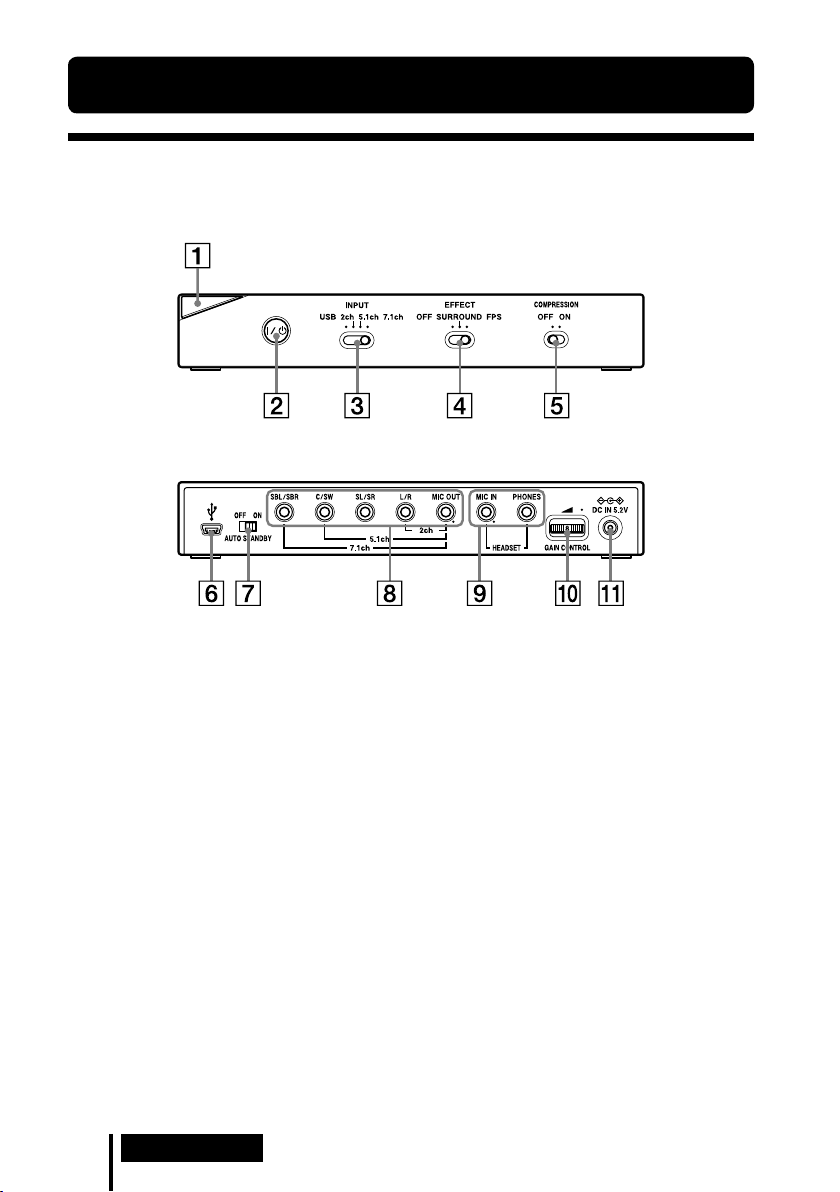
Location and Function of Parts
Digital Surround Processor Part Descriptions
Front panel of processor
Rear panel of processor
Power indicator
(See page 16)
/ (on / standby) switch
(See page 16)
INPUT (USB/2ch/5.1ch/7.1ch) switch
EFFECT (OFF/SURROUND/FPS) switch
(See page 17)
COMPRESSION (OFF/ON) switch
(See page 18)
* There is a tactile dot on the processor for easy recognition.
USB port
(See page 11)
AUTO STANDBY (OFF/ON) switch
(See page 19)
7.1ch/5.1ch/2ch (SBL/SBR, C/SW, SL/
SR, L/R, MIC OUT*) jacks
HEADSET (MIC IN
(See page 12)
GAIN CONTROL
(See page 19)
DC IN 5.2V jack
(See page 12)
*, PHONES) jacks
*

Headset Part Descriptions
Head-band
Earpads
Support-pads
Microphone
VOL (volume) control
(See page 16)
* There is a tactile dot on the headset for easy recognition.
*
MIC MUTING switch
(See page 16)
(headphone) plug (Black)
(microphone) plug (Red)
Preparation
US
7
Connection
Connecting the Headset system
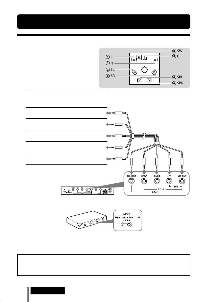
Step 1-: Connecting a 7.1ch Sound Device
1 Connect the processor to the
sound device as illustrated below.
Cable
plug
names
MIC
L / R
SL / SR
C / SW
SBL / SBR
Multi-channel cable
(supplied)
Connecting jacks of the sound
device*
MIC IN
Connect to MIC IN jack
L/R OUT
Connect to L/R OUT jack
Surround L/R OUT
Connect to SL/SR OUT jack
Center/Subwoofer OUT
Connect to C/SW OUT jack
Surround back L/R OUT
Connect to SBL/SBR OUT jack
* The jack name varies depending on the sound
device.
Rear panel of processor
2 Slide the INPUT switch to “7.1ch.”
Front panel of
processor
3 Set the 7.1ch speaker mode in the computer.
For details on operation of your computer/sound device, refer to the operating instructions
for it.
Do not connect the USB cable with multi-channel cable at the same time when you connect
the processor to the computer. The computer sound setting may be switched to an
unintended device.
US
8
Connection

Step 1-: Connecting a 5.1ch Sound Device
Connect the 5.1ch jacks of the processor by the supplied multi-channel cable. The EFFECT
function provides 7.1ch extended surround output from a 5.1ch input source.
1 Connect the processor to the
sound device as illustrated below.
Cable
plug
names
MIC
L / R
SL / SR
C / SW
SBL / SBR
Multi-channel cable
(supplied)
Connecting jacks of the sound
device*
MIC IN
Connect to MIC IN jack
L/R OUT
Connect to L/R OUT jack
Surround L/R OUT
Connect to SL/SR OUT jack
Center/Subwoofer OUT
Connect to C/SW OUT jack
Not connected
* The jack name varies depending on the sound
device.
Rear panel of processor
2 Slide the INPUT switch to “5.1ch.”
Front panel of
processor
3 Set the 5.1ch speaker mode in the computer.
For details on operation of your computer/sound device, refer to the operating instructions
for it.
Do not connect the USB cable with multi-channel cable at the same time when you connect
the processor to the computer. The computer sound setting may be switched to an
unintended device.
Connection
US
9

Step 1-: Connecting a 2ch Sound Device
Connect the 2ch jacks of the processor by the supplied multi-channel cable. The EFFECT
function provides 7.1ch extended surround output from a 2ch input source.
1 Connect the processor to the
sound device as illustrated below.
Cable
plug
names
MIC
L / R
SL / SR
C / SW
SBL / SBR
Multi-channel cable
(supplied)
Connecting jacks of the sound
device*
MIC IN
Connect to MIC IN jack
L/R OUT
Connect to L/R OUT jack
Not connected
Not connected
Not connected
* The jack name varies depending on the sound
device.
Rear panel of processor
2 Slide the INPUT switch to “2ch.”
Front panel of
processor
3 Set the 2ch speaker mode in the computer.
For details on operation of your computer/sound device, refer to the operating instructions
for it.
Do not connect the USB cable with multi-channel cable at the same time when you connect
the processor to the computer. The computer sound setting may be switched to an
unintended device.
US
10
Connection
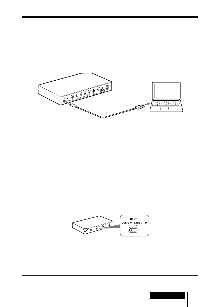
Step 1-: Connecting to the Computer Using the USB
cable
Connect the USB port on the computer to the USB port of the processor by the supplied USB
cable.
Although the processor works as an external 2ch sound device, the EFFECT functions provide
7.1ch extended surround from 2ch input.
1 Connect the processor to the computer.
to USB port
to USB port
Dedicated USB cable
(supplied)
USB drivers are included in operating systems such as Windows XP, Windows Vista, Windows
7 and Mac OS X. USB drivers will be installed automatically when the processor is turned on at
the first time after connecting and starting the computer.
When connecting to different USB ports, a computer may install USB drivers again.
Notes
The headset is not guaranteed to operate with a USB hub or USB extension cable. Use the supplied USB
cable only.
When the headset is connected to the computer, the volume level of the computer may be set to
maximum. Turn down the volume of the computer beforehand.
The sound of digital broadcasting might not be output via USB of the computer when connecting by the
USB cable. Connect it with the multi-channel cable if you cannot hear the sound of digital broadcasting
(page 8 to 10).
Computer
2 Slide the INPUT switch to “USB.”
Front panel of
processor
3 Check the sound settings of the computer.
For details on operation of your computer device, refer to the operating instructions for it.
Do not connect the USB cable with multi-channel cable at the same time when you connect
the processor to the computer. The computer sound setting may be switched to an
unintended device.
Connection
11
US
Step 2: Connecting the AC Adaptor
Connect the supplied AC adaptor to the processor, and then connect the AC adaptor to the
power outlet.
Rear panel of processor
To DC IN 5.2V jack
To power outlet
AC adaptor (supplied)
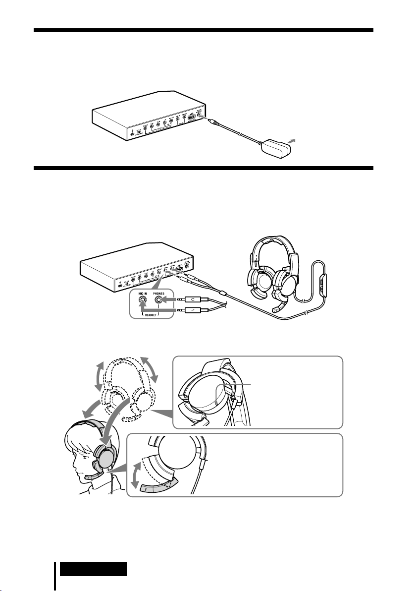
Step 3: Preparing the Headset
1 Connect the (microphone) plug of the headset to the HEADSET (MIC IN) jack of
the processor, and connect the (headphone) plug to the HEADSET (PHONES)
jack.
Rear panel of processor
Headset
Black
Red
2 Adjust the band of the headset, and wear the earpad marked on your right ear,
and the one marked on your left ear.
There is a tactile dot on the
hanger marked to
distinguish the left side.
Adjust the position of the
microphone for effective pickup of
your voice.
Return the position of the
microphone to rest near the earpad
when not in use.
Note
If the position of the microphone is not correct, the sensitivity of the microphone will decrease, and sound
from the headphone may enter the microphone.
US
12
Connection

Step 4: Checking the Settings of the Computer
To check the sound device settings of the computer
Before using the processor, check the setting of the sound device by following the instructions
below according to your operating system. For details on the operation of your computer/
sound device, refer to the operating instructions for it.
For Windows
Windows XP in Category View
Click the [start] menu, select [Control Panel], [Sounds, Speech and Audio Devices], [Sounds
and Audio Devices], [Audio] tab, and then select the regular sound device (or [USB PnP Sound
Device] if connection is by the supplied USB cable) for [Default device] in the Sound playback
or Sound recording menu.
Windows Vista
Click the [Start] menu, select [Control Panel], [Hardware and Sound], [Sound], [Playback] or
[Recording] tab, select the regular sound device (or [USB PnP Sound Device] if connection is
by the supplied USB cable) for the playback device or recording device, and then click [Set
default].
Windows 7
Click the [Start] menu, select [Control Panel], [Hardware and Sound], [Sound], [Playback] or
[Recording] tab, select the regular sound device (or [USB PnP Sound Device] if connection is
by the supplied USB cable) for the playback device or recording device, and then click [Set
default].
For Macintosh
Mac OS X
Click the [Apple] menu, select [System Preferences], [Sound], [Output] or [Input] tab, and then
select the regular sound device (or [USB PnP Sound Device] if connection is by the supplied
USB cable) for [Select a device for sound output] or [Select a device for sound input].
(Continued)
Connection
13
US

To adjust the volume level of the sound
When connecting the computer to the processor with the USB cable, adjust the volume level
using the VOL control on the headset.
When connecting with the multi-channel cable, you can adjust the volume level not only by the
VOL control on the headset, but also by changing the computer volume level as below.
For Windows
Windows XP in Category View
Click the [start] menu and select [Control Panel], [Sounds, Speech and Audio Devices],
[Sounds and Audio Devices], click [Volume] in Sound menu, and adjust the master volume
level.
Windows Vista
Click the [Start] menu and select [Control Panel], [Hardware and Sound], [Adjust system
volume], and adjust the master volume level.
Windows 7
Click the [Start] menu and select [Control Panel], [Hardware and Sound], [Adjust system
volume], and adjust the master volume level.
For Macintosh
Mac OS X
Click the [Apple] menu, select [System Preferences], [Sound], [Output] tab, and adjust the
speaker output level.
Notes
You may have to perform settings depending on the software. For details, refer to the operating
instructions of your software.
The headset volume and the output level of the computer are not synchronized.
To set for music CD playback
This setting is necessary when playing back a music CD in the CD-ROM drive, if connection is
by the supplied USB cable.
Follow the instructions below according to your operating system and click the check box of
[Enable digital CD audio for this CD-ROM device]. For Windows Vista, Windows 7 and
Macintosh, setting for music CD playback is not necessary.
For Windows XP in Category View
Click the [start] menu, and select [Control Panel], [Sounds, Speech and Audio Devices],
[Sounds and Audio Devices], and [Hardware] tab. Select the CD-ROM drive for playing music,
click [Properties], and then click the [Properties] tab. Click the check box of [Enable digital CD
audio for this CD-ROM device].
US
14
Connection

To adjust the volume level of the microphone
Before using the processor, check and adjust the volume level of the microphone by the
computer. Follow the instructions below according to your operating system, and check/adjust
the volume level.
For details on the operation of your computer, refer to the operating instructions for it.
For Windows
Before adjusting the volume of the microphone, check the input level of the microphone by
performing test recording with a sound recorder etc.
Windows XP in Category View
Click the [start] menu and select [Control Panel], [Sounds, Speech and Audio Devices],
[Sounds and Audio Devices], and [Audio] tab. Check that [Default device] in the Sound
recording menu is set to the regular sound device (or [USB PnP Sound Device] if connection is
by the supplied USB cable), click [Volume] in the Sound recording menu, and adjust the
microphone input level.
Windows Vista
Click the [Start] menu, select [Control Panel], [Hardware and Sound], [Sound], [Recording]
tab, and select the regular sound device (or [USB PnP Sound Device] if connection is by the
supplied USB cable) for the recording device and click [Set Default]. Select the regular sound
device (or [USB PnP Sound Device] if connection is by the supplied USB cable) again, click
[Properties], select the [Levels] tab, and adjust the microphone input level.
Windows 7
Click the [Start] menu, select [Control Panel], [Hardware and Sound], [Sound], [Recording]
tab, and select the regular sound device (or [USB PnP Sound Device] if connection is by the
supplied USB cable) for the recording device and click [Set Default]. Select the regular sound
device (or [USB PnP Sound Device] if connection is by the supplied USB cable) again, click
[Properties], select the [Levels] tab, and adjust the microphone input level.
For Macintosh
Mac OS X
Click the [Apple] menu, select [System Preferences], [Sound], [Input] tab, and adjust the
microphone input level.
Notes
The microphone does not support muting on the audio recording device of your computer. Slide the
MIC MUTING switch of the Headset to “ON” muting the microphone.
You may have to perform settings depending on the software. For details, refer to the operating
instructions of your software.
Connection
15
US

Operation
Listening to Sounds
1 Turn on the connected computer.
2 Press the
The power indicator of the processor lights white.
If you connect the USB port on the computer to the USB port of the processor by the
supplied USB cable, USB drivers will be installed automatically when the processor is
turned on at the first time after connecting and starting the computer.
3 Put on the headset.
(See page 12)
4 Start playback from the computer.
To adjust the volume
Adjust the volume level of the headset, and set the microphone muting mode.
/ (on / standby) switch to turn the processor on.
VOL (volume)
Adjust the volume level of
the headset.
MIC MUTING
ON: The microphone is set to
the MIC MUTING ON mode.
OFF: The microphone is set to
the MIC MUTING OFF mode.
Notes
When watching films, be careful not to increase the volume too high in quiet scenes. You may hurt your
ears when a loud scene is played.
The headset volume and the output level of the computer are not synchronized. Also note that the
microphone muting mode is not synchronized.
The music/sound might not be output from the headset if you connect to the processor by the USB cable
and slide the INPUT switch to “USB” while using music software. In this case, restart the music software.
US
16
Operation

To select your preferred sound field (EFFECT function)
The EFFECT switch allows you to select your preferred sound field.
With 5.1ch, 2ch, or via USB connection when “FPS” or “SURROUND” is selected, the built-in
Dolby Pro Logic IIx decoding will provide a similar sense of realism to 7.1ch. However, if the
INPUT switch position does not match the connection, the EFFECT function will not work
properly.
Front panel of the processor
Position of switch Sound field mode and suitable sound source
FPS (First Person Shooting) This setting provides clear localization of sounds respective of image.
This is the recommended setting for FPS where locality of sounds need to be
accurately perceived. The sound is listener-friendly, natural, clear and realistic. It
is characterized by very sharply perceived localization of all channels.
SURROUND This setting provides a seamless reproduction of all channels.
The overall sound is perceived more as a whole than with the FPS mode, and
provides the best sound field for playing multichannel surround games in general.
Also recommended for movie watching.
OFF 2ch sound is output.
A multichannel source (7.1ch/5.1ch) is downmixed to 2ch sound.
Note
The EFFECT function does not work for monaural sound sources.
About property of sound with the EFFECT function
The EFFECT function may not be obtained from sound sources that do not incorporate video, such as
music CDs.
VPT (Virtualphones Technology) simulates the average human HRTF (head-related transfer function)*.
The effect is perceived differently, depending on individual.
* HRTF = Head-Related Transfer Function. A mathematical measurement to show changes in sound
between the source and your ears.
(Continued)
Operation
17
US

To make the sound comfortable to hear (COMPRESSION function)
Slide the COMPRESSION switch to ON.
This function maintains the overall level of program material: explosive sounds are attenuated while lower
level sounds (footsteps, etc.) are enhanced. It is very effective for limiting high dynamic range source
material.
Front panel of the processor
Note
Check carefully the volume control with the COMPRESSION function.
With the COMPRESSION function on, the sound may seem loud with when the audio signal from the
computer is comparatively low. In this case, increase the computer’s volume gradually, and set where overall
sound is consistent. Conversely, the sound may be felt to be too low. In this case, decrease the computer’s
volume gradually, and set for the most consistent overall sound.
Illustration of the compression process
explosion
dynamic range
dialogue
footsteps, background noise
input signal
compression
output signal
explosion
dialogue
footsteps, background noise
standard
Dynamic range compression by built-in
DSP (Digital Signal Processor) processor
Uncomfortable
dynamic range
Easy to hear
Difficult to hear
18
US
Operation

To adjust the volume level from the sound device
OFF
AUTO STANDBY
ON
(GAIN CONTROL)
The GAIN CONTROL adjusts the volume according to the rated output of the sound device
(initial setting is “8”). Increase the GAIN CONTROL more than “8” if the output is low, even
when the volume of the sound device is maximized. And if sound is distorted, decrease the
volume level of the output on the sound device.
Rear panel of the processor
Rotate left to
decrease the
level
Sound device
rated output
More than 2Vrms Adjust the GAIN CONTROL level to “8,” and then adjust the audio output device
2Vrms This processor is calibrated for 2Vrms standard output to the sound device when
Less than 2Vrms “8” - “10,” the GAIN CONTROL level adjust for the louder volume.
GAIN CONTROL level
to lower the sound.
the GAIN CONTROL is set to “8.”
Rotate right
to increase
the level
To set the system to enter the standby mode automatically
(AUTO STANDBY function)
The processor enters the standby mode automatically if the processor does not input sound for
about 30 minutes.
You can turn the AUTO STANDBY function ON/OFF by the AUTO STANDBY switch.
Rear panel of the processor
Position of switch Effect
ON The AUTO STANDBY function will work. Turn on the system again by pressing
the / (on / standby) switch.
OFF The AUTO STANDBY function will not work.
Operation
19
US

Additional Information
Troubleshooting
If you run into any problems using this system, use the following checklist. Should any problem
persist, consult your nearest Sony dealer.
Symptom Cause and remedy
No sound
Distorted or intermittent
sound (sometimes with
noise)
Low sound
Check the connection between the processor and the computer.
Turn on the computer connected to the processor, and start playback.
Turn on the processor.
The INPUT setting does not match the actual connection method. (Example:
the input signal is USB, the INPUT setting is 7.1ch, etc.)
Set the INPUT switch to the appropriate input signal.
Increase the headset volume.
Connect the headphone plug properly.
Increase the volume level of the computer and the music playback software.
The system is connected while music software is in use.
Restart the music software.
The sound device of your computer is not set correctly (page 13).
The volume control of your computer or the music playback software, etc., is
set to mute.
Unset mute.
The GAIN CONTROL level is “0.”
Increase the GAIN CONTROL.
Your computer does not recognize the headset as a USB device if connection is
by the supplied USB cable.
Restart your computer.
The CD-ROM drive of your computer does not support the digital play
function if connection is by the supplied USB cable.
Use a CD-ROM drive that supports the digital playback function.
Digital broadcasts might not be heard with the USB connection.
Connect the computer by the multi-channel cable (page 8 to 10).
AUTO STANDBY activated because no sound was input for approx. 30
minutes.
Turn on the processor again.
Decrease the volume level on the connected computer.
Increase the volume level on the connected computer and the music playback
software.
Increase the headset volume.
Increase the GAIN CONTROL.
20
US
Additional Information

Symptom Cause and remedy
Loud background noise
The surround sound effect
is not obtained
Sound is disrupted
No sound from the
microphone
Low sound from the
microphone
Recorded sound from the
microphone is noisy
Distorted sound from the
microphone
The MIC MUTING switch
does not work
The computer output level
settings of the center
speaker and subwoofer may
be reversed.
If you connect the processor to a computer using the multi-channel cable,
increase the volume level on the connected sound device.
Separate the processor from the computer.
The INPUT setting does not match the actual connection method. (Example:
the input signal is 2ch, the INPUT setting is 7.1ch, etc.)
Set the INPUT switch to the appropriate input signal.
Set the EFFECT switch to “FPS” or “SURROUND” (page 17).
The surround effect does not work for monaural sound sources.
The INPUT setting does not match the actual connection method. (Example:
the input signal is 2ch, the INPUT setting is 7.1ch, etc.)
Set the INPUT switch to the appropriate input signal.
The CPU of your computer is overloaded, if connection is by the supplied USB
cable.
Exit other unnecessary applications.
Other USB devices are connected to your computer and being used
simultaneously while connected by the supplied USB cable.
Quit operating other USB devices.
Connect the microphone plug properly.
The MIC MUTING switch on the headset is set to “ON.”
Slide the MIC MUTING switch to “OFF.”
The audio recording device of your computer is not set correctly (page 13).
Connect the microphone plug properly.
Move the microphone to the correct position.
The volume level of the microphone is set too low on the computer.
Increase the volume level of the microphone on the computer.
There are electrical wires, fluorescent lights, or mobile phones near the headset
(especially the microphone).
Move away from any possible sources of electromagnetic interference.
Headphone sound leaked to the microphone.
Move the microphone to the correct position.
The volume level of the microphone is set too high on the computer.
Decrease the volume level of the microphone on the computer.
The computer’s microphone input is already muted.
Cancel microphone muting on the computer.
Depending on the computer, the computer output level settings of the center
speaker and subwoofer may be reversed. Before changing the computer output
level, refer to the operating instructions for details on operation of your
computer.
Additional Information
21
US
 Loading...