

Sony DNW-A75 BETACAM SX, DNW-A75P BETACAM SX Operation Manual

DIGITAL VIDEOCASSETTE RECORDER
DNW-A75/A75P
OPERATION MANUAL
1st Edition (Revised 4)
[English]

WARNING
To prevent fire or shock hazard, do not
expose the unit to rain or moisture.
To avoid electrical shock, do not open
the cabinet. Refer servicing to qualified
personnel only.
This apparatus must be earthed.
WARNING: THIS WARNING IS APPLICABLE FOR USA
ONLY.
If used in USA, use the UL LISTED power
cord specified below.
DO NOT USE ANY OTHER POWER CORD.
Plug Cap Parallel blade with ground pin
(NEMA 5-15P Configuration)
Cord Type SJT, three 16 or 18 AWG
wires
Length Less than 2.5 m (8 ft 3 in)
Rating Minimum 10 A, 125 V
Using this unit at a voltage other than 120V
may require the use of a different line cord or
attachment plug, or both. To reduce the risk
of fire or electric shock, refer servicing to
qualified service personnel.
For the customers in Europe
This product with the CE marking complies with both the
EMC Directive (89/336/EEC) and the Low Voltage Directive
(73/23/EEC) issued by the Commission of the European
Community.
Compliance with these directives implies conformity to the
following European standards:
EN60065: Product Safety
EN55103-1: Electromagnetic Interference (Emission)
EN55103-2: Electromagnetic Susceptibility (Immunity)
This product is intended for use in the following
Electromagnetic Environment (s):
E1 (Residential), E2 (Commercial and light industrial), E3
(Urban outdoors) and E4 (Controlled EMC environment
ex. TV studio)
Pour les clients européens
Ce produit portant la marque CE est conforme à la fois à la
Directive sur la compatibilité électromagnétique (EMC) (89/
336/CEE) et à la Directive sur les basses tensions (73/23/
CEE) émises par la Commission de la Communauté
européenne.
La conformité à ces directives implique la conformité aux
normes européennes suivantes:
• EN60065: Sécurité des produits
• EN55103-1: Interférences électromagnétiques (émission)
• EN55103-2: Sensibilité électromagnétique (immunité)
Ce produit est prévu pour être utilisé dans les
environnements électromagnétiques suivants:
E1 (résidentiel), E2 (commercial et industrie légère), E3
(urbain extérieur) et E4 (environnement EMC contrôlé ex.
studio de télévision).
This symbol is intended to alert the user to
the presence of important operating and
maintenance (servicing) instructions in the
literature accompanying the appliance.
For the customers in the USA
This equipment has been tested and found to comply with
the limits for a Class A digital device, pursuant to Part 15 of
the FCC Rules. These limits are designed to provide
reasonable protection against harmful interference when
the equipment is operated in a commercial environment.
This equipment generates, uses, and can radiate radio
frequency energy and, if not installed and used in
accordance with the instruction manual, may cause harmful
interference to radio communications. Operation of this
equipment in a residential area is likely to cause harmful
interference in which case the user will be required to
correct the interference at his own expense.
You are cautioned that any changes or modifications not
expressly approved in this manual could void your authority
to operate this equipment.
The shielded interface cable recommended in this manual
must be used with this equipment in order to comply with
the limits for a digital device pursuant to Subpart B of Part
15 of FCC Rules.
Für Kunden in Europa
Dieses Produkt besitzt die CE-Kennzeichnung und erfüllt
sowohl die EMV-Direktive (89/336/EEC) als auch die
Direktive Niederspannung (73/23/EEC) der EGKommission.
Die Erfüllung dieser Direktiven bedeutet Konformität für die
folgenden Europäischen Normen:
• EN60065: Produktsicherheit
• EN55103-1: Elektromagnetische Interferenz (Emission)
• EN55103-2: Elektromagnetische Empfindlichkeit
(Immunität)
Dieses Produkt ist für den Einsatz unter folgenden
elektromagnetischen Bedingungen ausgelegt:
E1 (Wohnbereich), E2 (kommerzieller und in beschränktem
Maße industrieller Bereich), E3 (Stadtbereich im Freien)
und E4 (kontrollierter EMV-Bereich, z.B. Fernsehstudio)

Table of Contents
Chapter 1
Overview
Chapter 2
Location and Function of
Parts
Chapter 3
Preparations
1-1 Features ........................................................................................... 1-1
1-2 Example System Configurations...................................................1-3
2-1 Control Panels................................................................................. 2-1
2-1-1 Upper Control Panel ...............................................................2-2
2-1-2 Lower Control Panel...............................................................2-7
2-1-3 Subsidiary Control Panel ...................................................... 2-16
2-2 Connector Panel ........................................................................... 2-19
3-1 Connections to External Devices...................................................3-1
3-1-1 Connections to Digital Devices ..............................................3-1
3-1-2 Connections to Analog Devices..............................................3-2
3-2 Reference Signals for Video Output and Servo System .............. 3-3
3-2-1 External Sync Signal for the Internal Reference Video Signal
Generator................................................................................ 3-3
3-2-2 Reference Signal for the Servo System .................................3-4
3-2-3 Connecting Reference Signals...............................................3-5
3-3 Setup ................................................................................................ 3-7
3-4 Superimposed Character Information ......................................... 3-8
3-5 Cassettes ........................................................................................ 3-10
3-5-1 Cassette Types...................................................................... 3-10
3-5-2 Inserting and Ejecting Cassettes .......................................... 3-10
3-5-3 Preventing Accidental Erasure of Recordings .....................3-11
Chapter 4
Recording and Playback
Chapter 5
Editing
4-1 Recording ........................................................................................ 4-1
4-1-1 Preparations for Recording .................................................... 4-1
4-1-2 Recording Time Code and User Bit Values ........................... 4-2
4-1-3 Recording Procedure ............................................................. 4-5
4-2 Playback .......................................................................................... 4-6
4-2-1 Preparations for Playback ...................................................... 4-6
4-2-2 Playback/Feed Play Procedures.............................................4-7
4-2-3 Dynamic Motion Control (DMC) Playback ......................... 4-11
5-1 Automatic Editing ..........................................................................5-1
5-1-1 Overview ............................................................................... 5-1
5-1-2 Switch Settings ...................................................................... 5-2
5-1-3 Selecting the Editing Mode ................................................... 5-3
5-1-4 Setting Edit Points .................................................................. 5-3
5-1-5 Modifying and Deleting Edit Points ....................................... 5-6
5-1-6 Cue-up to Edit Points and Preroll ........................................... 5-7
5-1-7 Preview ................................................................................... 5-7
5-1-8 Carrying Out Automatic Editing............................................. 5-8
5-2 DMC Editing.................................................................................. 5-10
5-2-1 Overview of DMC Editing ................................................... 5-10
5-2-2 Carrying Out DMC Editing .................................................. 5-11
5-3 Special Automatic Editing Methods ............................................ 5-12
5-3-1 Quick Editing........................................................................5-12
5-3-2 Continuous Editing ............................................................... 5-12
5-3-3 Standalone Editing................................................................5-13
5-3-4 Manual Editing ..................................................................... 5-13
5-3-5 Preread Editing ..................................................................... 5-13
Table of Contents 1

Table of Contents
Chapter 6
Shot Mark Function
Chapter 7
Menu System
Chapter 8
Maintenance and
Inspection
6-1 Overview..........................................................................................6-1
6-2 Shot Mark Operation Menu..........................................................6-2
6-3 Shot Mark Operations ................................................................... 6-3
6-3-1 Reading Shot Marks .............................................................. 6-3
6-3-2 Writing Shot Marks ............................................................... 6-3
6-3-3 Shot Mark List Operations .................................................... 6-4
6-3-4 Cueing Up to Shot Marks ...................................................... 6-6
6-3-5 Reading in Shot Data ............................................................. 6-7
6-3-6 Sorting Shot Marks ................................................................ 6-8
7-1 Menu System Configuration ......................................................... 7-1
7-2 Basic Menu...................................................................................... 7-1
7-2-1 Items in the Basic Menu ........................................................7-1
7-2-2 Basic Menu Operations.......................................................... 7-4
7-3 Extended Menu............................................................................... 7-9
7-3-1 Items in the Extended Menu .................................................. 7-9
7-3-2 Extended Menu Operations ................................................. 7-25
8-1 Removing a Cassette When Tape Slack Occurs .......................... 8-1
8-2 Head Cleaning ................................................................................ 8-1
8-3 Moisture Condensation..................................................................8-2
8-4 Digital Hours Meter ....................................................................... 8-3
Appendix
Specifications......................................................................................... A-1
Index ....................................................................................................... I-1
2 Table of Contents
1-1 Features
Chapter 1 Overview
The DNW-A75/A75P is a digital videocassette
recorder, based on the Betacam SX format.
This unit not only offers digital recording and
playback, but can also play back tapes recorded in the
conventional analog Betacam format.
The following are some of the features of the system.
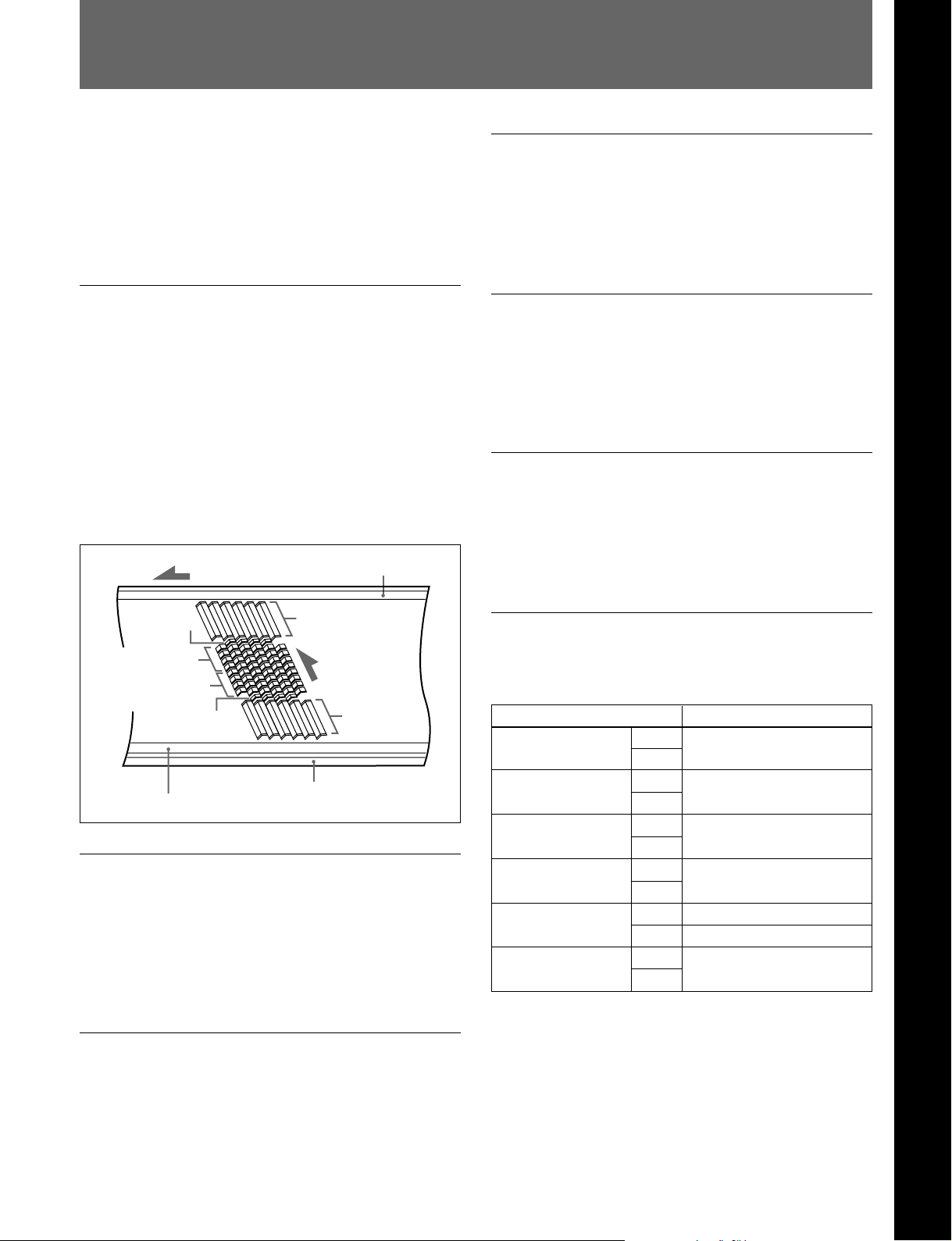
Betacam SX format
The Betacam SX format was developed as a digital
version of the Betacam SP format, and is a digital VTR
format supporting nonlinear editing systems and server
systems. Compared with analog Betacam, the
Betacam SX format reduces the tape speed to
approximately one-half. The drum rotates at 75
revolutions per second, recording two frames of video
data and four channels of digital audio in ten diagonal
tracks. The longitudinal control and time code tracks
are the same as in the analog Betacam format.
Tape transport direction
Auxiliary track
High image quality, high audio quality,
high reliability
Chapter 1 Overview
Even with a low data rate, recording and playback with
high image quality and high audio quality is achieved.
The unit also has a powerful error-correcting system.
Data compression by interframe encoding
This is the first VTR to perform data compression by
MPEG-2 interframe encoding conforming to 4:2:2
Profile @ Main level. The data rate is reduced by a
factor of 10.
Playback compatibility with Betacam/
Betacam SP
This unit can play tapes recorded in Betacam/Betacam
SP format. This makes for efficient use of existing
material in Betacam/Betacam SP format.
System data
Audio channels
1 to 4
Audio channels
1 to 4
System data
Control (CTL) track
Video
Head
direction
Video
Time code track
Head configuration
In addition to digital recording and playback heads for
Betacam SX, the unit also has analog playback heads
for Betacam SP. There are eight digital playback
heads, allowing CONFI playback (simultaneous
playback) for checking recording.
Digital signal processing
Wide range of input and output signals
You can use the following wide range of input and
output signals.
Signals Standard or option
Analog video Input Fitted as standard
Output
Analog audio
(4 channels)
AES/EBU digital
audio
a)
SDI
video/audio Input Fitted as standard
b)
SDTI
video/audio Input
Time code Input Fitted as standard
a) Serial Digital Interface
b) Serial Data Transport Interface
Input Fitted as standard
Output
Input Fitted as standard
Output
Output
Output
Output
(composite and component)
Option
Option (BKNW-118)
This unit processes digital signals conforming to 4:2:2
component digital D-1 format.
Chapter 1 Overview 1-1

1-1 Features
Chapter 1 Overview
Powerful editing functions
With two of these units together, you can carry out
automatic or manual editing, using either assemble or
insert editing.
The system also provides a powerful range of
functions for setting and amending edit points,
preview, review, and other aspects of efficient editing.
DMC (dynamic motion control) editing
You can save a varying speed, in the range -1 to +2
times normal speed, for an editing segment, and
automatically edit with this varying speed.
Split editing
In insert editing, this allows the audio IN and OUT
points to be set independently.
Preread editing
The audio or video on the tape can be read out,
processed, and rerecorded with no time shift, using the
preread heads.
Cross-fade editing
For audio editing, you can select from cut-in editing,
fade-in editing, and fade-in/fade-out editing.
Menu-based setup
Initial settings for the unit’s operating condition, the
interfaces with connected equipment, and so forth can
be made by menu operations on the front panel of the
unit.
Wide range of indications
In addition to the LED display which shows the
operating status and current settings of this unit and
connected equipment, a fluorescent display displays
numerical values including time code, user bits, editing
IN and OUT points, editing durations, error messages
and setup menu information.
Selection of external/internal time code
You can record using either an external time code or
the output of the built-in time code generator. You can
also synchronize the built-in time code generator to an
external time code.
Connection to external control devices
It is possible to connect a BVE-900/910/2000/9000/
9000P/9100/9100P or other BVE-series editor, a
control and monitoring computer, a BVR-50/50P
remote controller for the built-in digital video
processor, and so forth.
Economy
•You can use a variety of tapes, including low-priced
tapes for UVW-series VTRs and tapes for Betacam
SP or Betacam SX format. Using large cassettes,
recording of 180 minutes or more is possible.
•The design needs minimal maintenance, and requires
no daily maintenance or checks. The drum and other
components have reduced maintenance costs.
Rack mounting
The unit can be mounted in an EIA standard 19-inch
rack.
1-2 Chapter 1 Overview
For details of rack mounting, refer to the Maintenance
Manual Part 1.
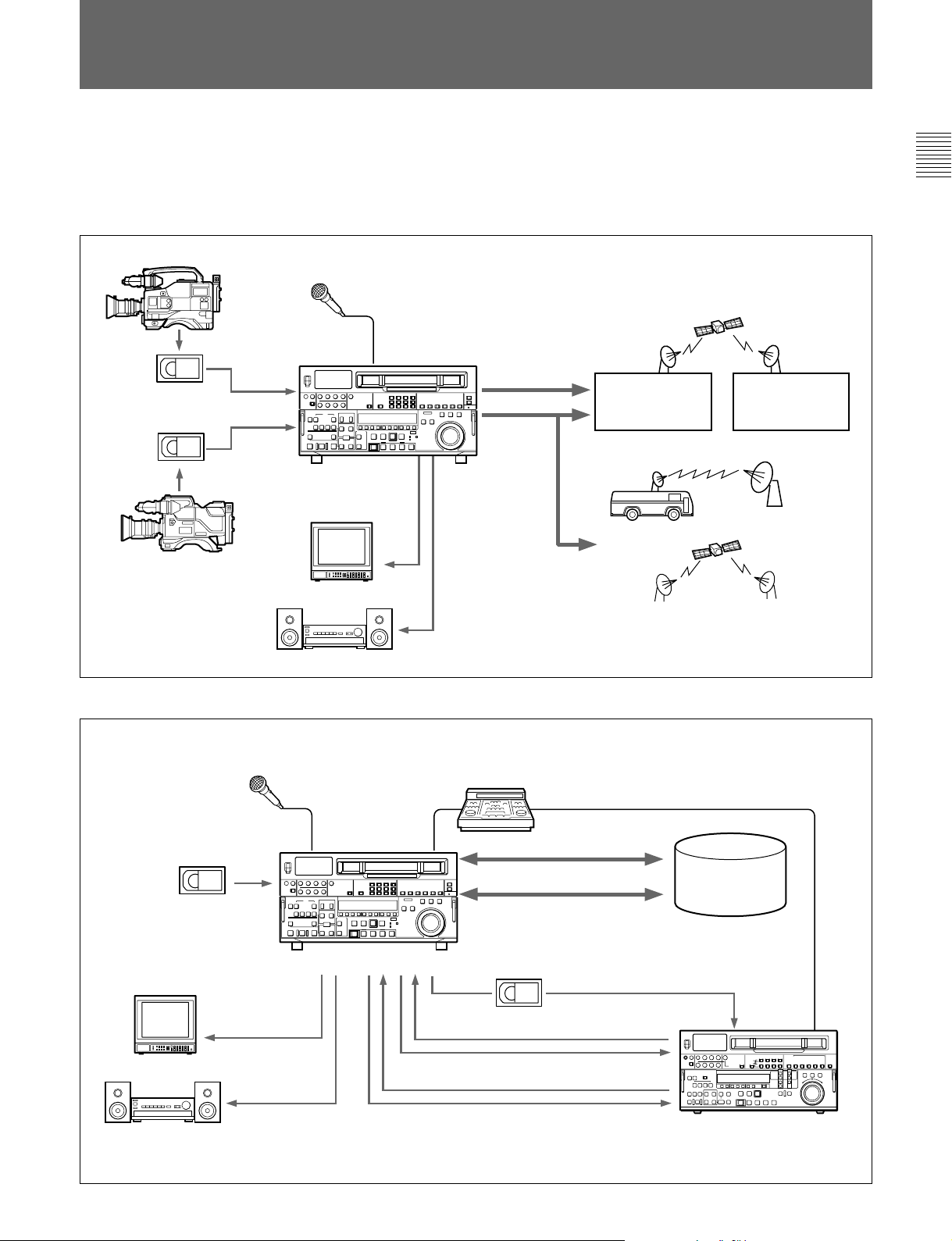
1-2 Example System Configurations
The following conceptual diagrams show examples of
use in an outside broadcast van or local station and
within a broadcasting station.
•Operation in an outside broadcast van or local station
Betacam SX camcorder
Microphone
Digital (SDTI/SDI)
Digital cassette
Analog cassette
DNW-A75/A75P
Analog
composite
Analog
composite
Analog audio
SNG a) system
Digital modulator
Chapter 1 Overview
Digital
demodulator
Betacam SP camcorder
Video monitor
Audio monitor
•Operation in a broadcasting station
Microphone
Digital/analog cassette
DNW-A75/A75P
Video monitor
Analog composite
BVE-series editor
Digital cassette
Tape control
SDTI
SDI
a) SNG: Satellite News Gathering
Audio/video
server
system
Audio monitor
Analog composite/component
SDIAnalog audio
VTR with SDI connectors
or analog VTR
Chapter 1 Overview 1-3


2-1 Control Panels
There are three control panels, as follows:
•Upper control panel
•Lower control panel
•Subsidiary control panel
Chapter 2 Location and Function of Parts
Chapter 2 Location and Function of Parts
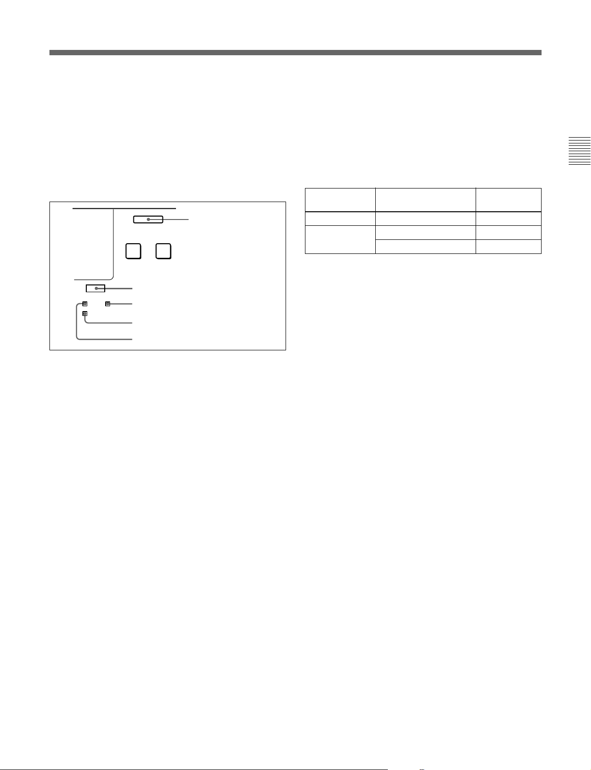
Upper control panel
(See page 2-2.)
VI TC UB
INTRP A IN DF LTC VITC 8F 4F 2F
A OUT
TCG TOTAL REMAIN 525 625
CONFI ON
DOLBY
NR
EVENT
%
a) To reveal the subsidiary control panel, pull the lower control panel forward.
Subsidiary control panel
(See page 2-16.)
Lower control panel
(See page 2-7.)
a)
Chapter 2 Location and Function of Parts 2-1
2-1 Control Panels
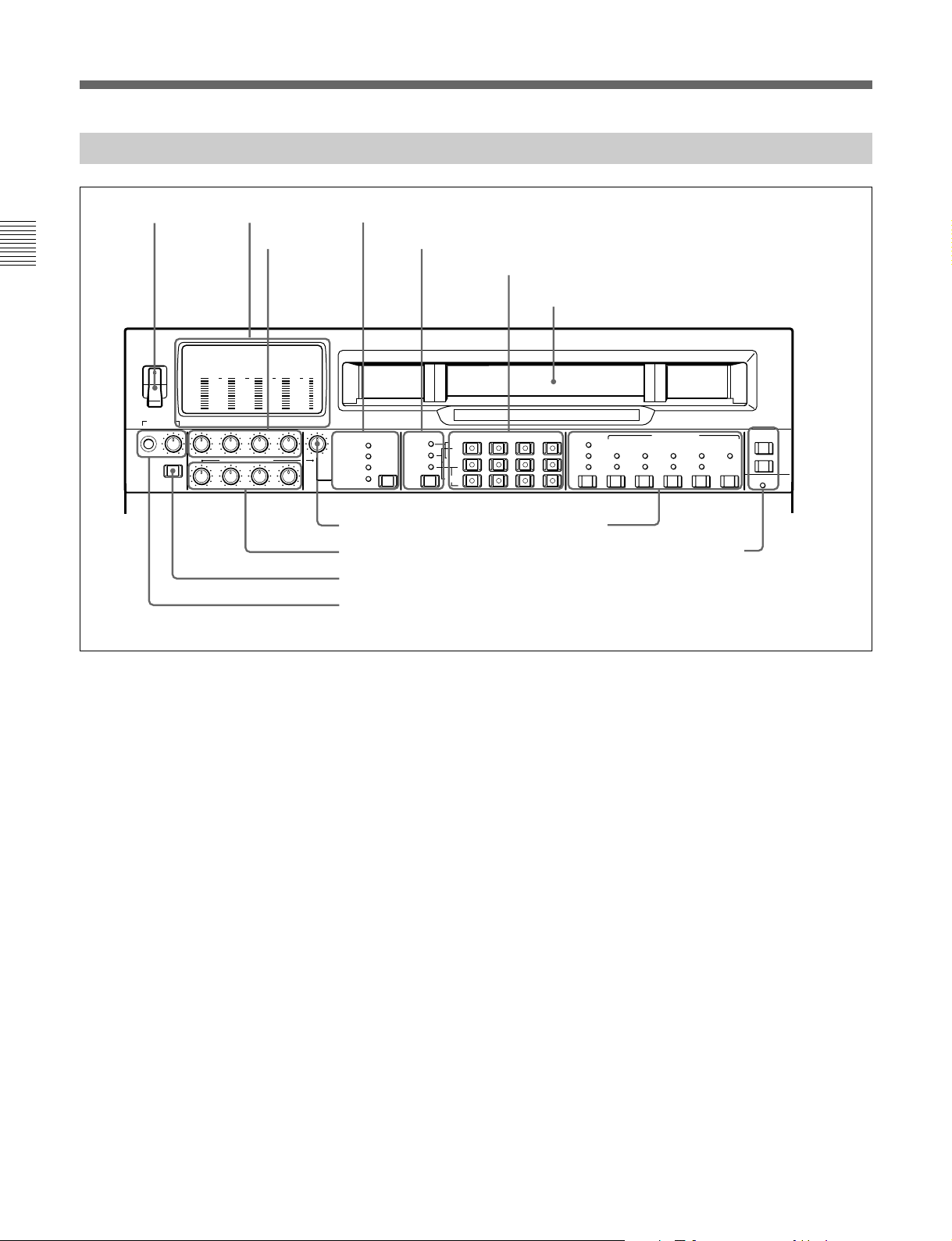
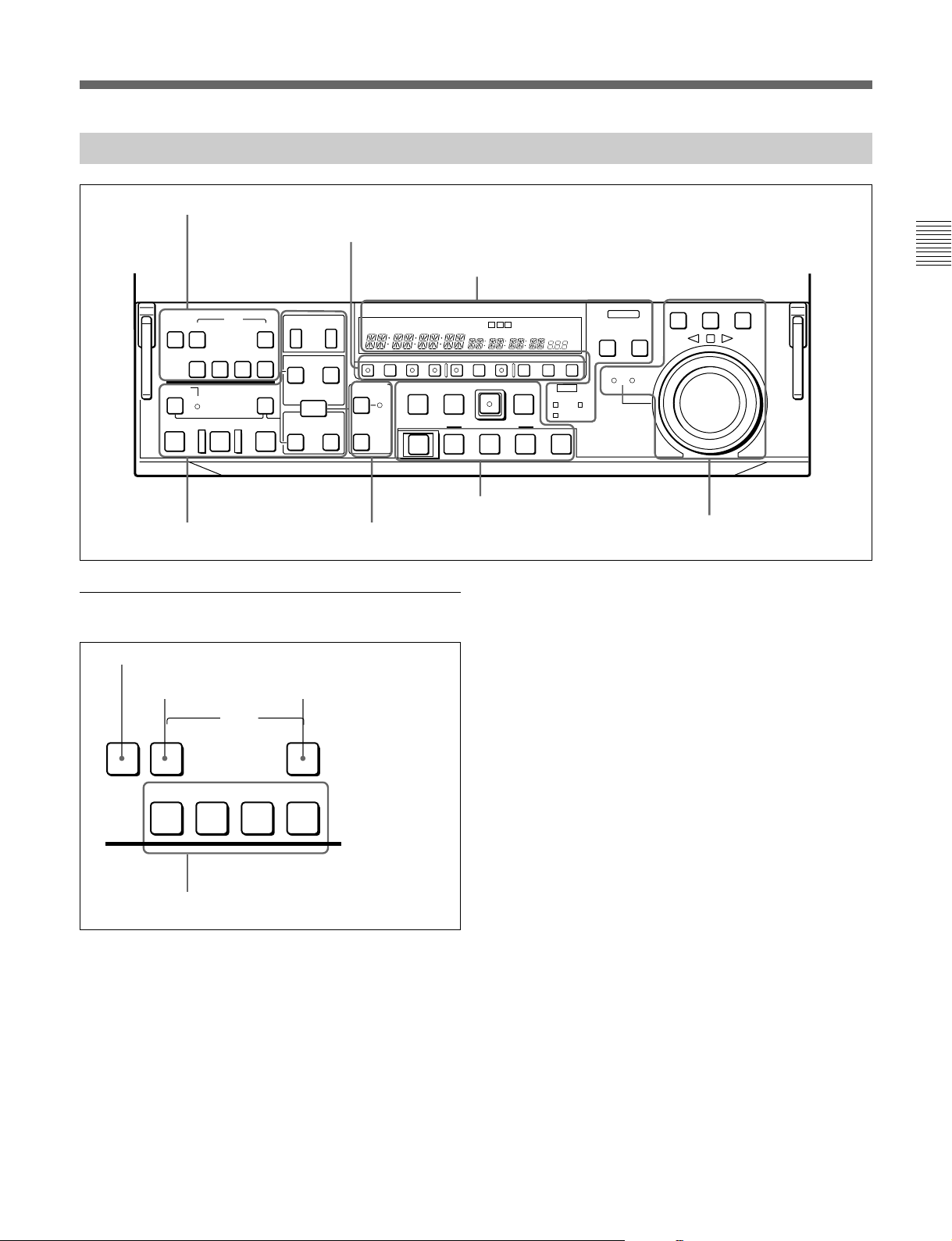
2-1-1 Upper Control Panel
1 POWER
switch
Chapter 2 Location and Function of Parts
POWER
ON
OFF
PHONES
DISPLAY
FULL/FINE
2 Level meters
3 REC controls
dB
dB
0
0
-10
-10
-20
-20
-30
-30
-40
-40
-80
-80
CH-1 CH-2 CH-3 CH-4 VIDEO
PULL FOR VARIABLE
dB
dB
0
0
-10
-10
-20
-20
-30
-30
-40
-40
-80
-80
REC
PB
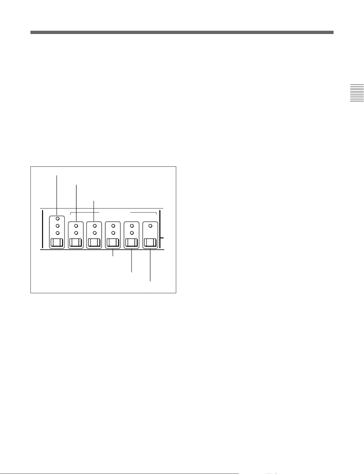
4 VIDEO INPUT SELECT switch and indicators
5 Audio selection function selector switch and indicators
2
0
-2
-4
(VIDEO&AUDIO)
AUDIO SELECT
MIXING
INPUT
MONITOR
VIDEO INPUT SELECT
SDT I
SDI
COMPONENT
(Y-R,B)
COMPOSITE
7 VIDEO control
8 PB controls
9 DISPLAY FULL/FINE switch
0 PHONES jack and control
6 Audio signal selection buttons
Cassette compartment
ANALOG / DIGITAL
AUTO
TC
LTC
INT
VITC
PRESET
EXT
REGEN
CH-1 CH-2 CH-3 CH-4
EXT
SDI
REC CH
AES/EBU
L
ANALOG
R
!¡ Time code setting
section
!™ REMOTE buttons and RS-232C indicator
TC GENERATOR
FREE
RUN
REC
RUN
REMOTE
1(9P)
VITC
DF
ON
NDF
2(50P)
RS232C
1 POWER switch
This powers the unit on and off. When the unit is
powered on, the level meters 2 and the fluorescent
display in the lower control panel light.
To power the unit off, press the side of the POWER
switch marked “OFF”.
3 REC (recording) controls
These individually adjust the recording levels on
channels 1 to 4.
To set the recording level, put the unit in E-E mode,
pull out the control knobs and adjust the level while
watching the level meters 2.
When the control knobs are pushed in, the recording
2 Level meters
These show the audio levels of channels 1 to 4
1)
(recording levels in recording mode or E-E mode
and
playback level in playback mode) and the video levels
levels return to the preset levels (0 dBm reference level
for an input of +4 dBm), and cannot be adjusted.
These controls do not function when SDTI video input
is selected.
of input composite video signals.
There are two modes for audio level indications:
FULL and FINE, selected by the DISPLAY FULL/
FINE switch 9.
..........................................................................................................................................................................................................
1) E-E mode: Abbreviation of “Electric-to-Electric mode”.
In this mode, video and audio signals input to the VTR
are output after passing through internal electric circuits,
but not through magnetic conversion circuits such as
heads and tapes. This can be used to check input signals
and for adjusting input signal levels.
For details of selecting the E-E mode, see the description of
the REC button in the tape transport control section (see
page 2-13) and the PB.EE button in the monitor/menu/
display setting section (see page 2-8).
2-2 Chapter 2 Location and Function of Parts
4 VIDEO INPUT SELECT switch and indicators
This switch selects the video input signal in the
following sequence.
SDTI n SDI n COMPONENT n COMPOSITE
To select SDTI requires the option for SDTI input.
SDTI: SDTI video signal input to the SDTI INPUT
connector (In this case the SDTI audio signals are
simultaneously selected.)
SDI: SDI video signal input to the SDI INPUT
connectors
COMPONENT: Analog component video signal
input to the COMPONENT VIDEO INPUT
connectors
COMPOSITE: Analog composite video signal input
to the COMPOSITE VIDEO INPUT connectors
The indicators light according to the selection. If there
is a fault on the selected input (such as no input
signal), the indicator flashes.
Using a video test signal
Holding down the VIDEO INPUT SELECT switch for
at least three seconds lights all four of the indicators,
and causes an internal signal generator to produce a
video test signal.
To stop the production of the video test signal, press
this switch and release within three seconds.
When the VIDEO INPUT SELECT switch is set to
SDTI, you cannot use the video test signal.
It is only possible to use this function when extended menu
item 710 is set to select a video test signal.
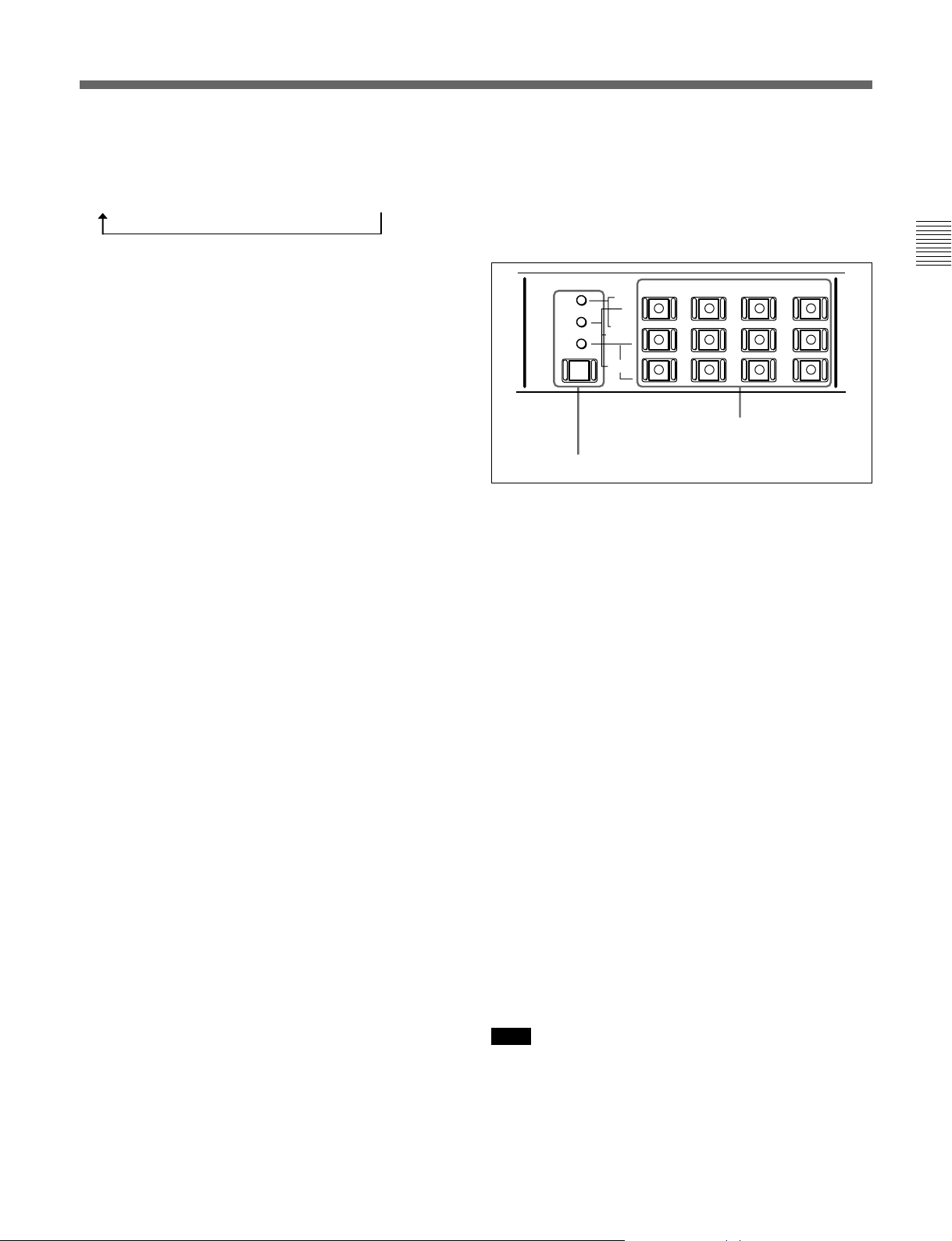
5 Audio selection function selector switch and
indicators
Pressing this switch lights the MIXING indicator,
INPUT indicator and MONITOR indicator cyclically,
and selects the function of the audio signal selection
buttons.
AUDIO SELECT
MIXING
INPUT
MONITOR
Audio selection function selector switch and indicators
CH-1 CH-2 CH-3 CH-4
EXT
SDI
REC CH
AES/EBU
L
ANALOG
R
Audio signal selection buttons
When the MIXING indicator is lit: You can use the
EXT and REC CH rows of the audio signal
selection buttons to switch the audio signals to be
recorded or carry out mixing.
When the INPUT indicator is lit: You can use the
SDI, AES/EBU, and ANALOG L/R rows of the
audio signal selection buttons to select the audio
input signals.
When the MONITOR indicator is lit: You can use
the L and R rows of the audio signal selection
buttons to select the audio output channels.
Using an audio test signal
Press the audio selection function selector switch
several times until the INPUT indicator lights. Then
press the CH-1 button in the SDI row, the AES/EBU
row, or the ANALOG row and keep it pressed for
three seconds or longer. When you release the button,
all of the audio signal selection buttons light and an
internal signal generator produces an audio test signal.
To stop the production of the audio test signal, press
the audio selection function selector switch so that
only the INPUT indicator is lit. Then press any of the
audio signal selection buttons, releasing the button
within three seconds.
Chapter 2 Location and Function of Parts
Note
When the VIDEO INPUT SELECT switch is set to
SDTI, you cannot use the audio test signal.
It is only possible to use this function when extended menu
item 808 is set to select an audio test signal.
Chapter 2 Location and Function of Parts 2-3

2-1 Control Panels
6 Audio signal selection buttons
The function of these buttons depends on the setting of
the audio selection function selector switch as follows.
When the MIXING indicator is lit
To select which input channel is to be recorded on
Chapter 2 Location and Function of Parts
which channel, press one of the buttons (CH-1 to CH-
4) in the EXT row while holding down one of the
buttons (CH-1 to CH-4) in the REC CH row.
For example, if you press the CH-2 button in the EXT
row while pressing the CH-1 button in the REC CH
row, signals from input channel 2 are recorded on
channel 1.
If you press two buttons in the EXT row
simultaneously, signals from the corresponding two
channels are mixed and recorded on the same channel.
Note
Before selecting signals from two input channels for
recording in one recorder channel, check to be sure
that the emphasis settings (ON or OFF) of the two
input channels are the same. Recording and playback
of mixed signals cannot be carried out correctly if the
emphasis settings are different.
You can check the settings in the channel display
section of the level meters. [EMPH] is displayed for
channels with the emphasis setting on.
The button that was pressed in the REC CH row
remains lit after you have finished making the settings.
When you press the lit button in the REC CH row, the
selected button or buttons in the EXT row light up
again. This allows you to check the settings. To cancel
the settings, press the corresponding button in the REC
CH row while pressing the button for the same channel
in the EXT row.
Adjusting the recording level when the MIXING
indicator is lit
Adjust by rotating the REC knob for the player
channel while viewing the level meter for the recorder
channel.
For example, when recording player channel 1 signals
on recorder channel 2, rotate the CH-1 REC knob
while viewing the level meter for CH-2.
When the INPUT indicator is lit
For each channel, press the button in the SDI row, the
AES/EBU row, or the ANALOG row.
The pressed button lights and the corresponding audio
input signal is selected.
However, when the video input signals selected with
the VIDEO INPUT SELECT switch are SDTI, the
audio input signals for all channels are also set to
SDTI.
When the MONITOR indicator is lit
Press the buttons in the L and R rows to select the
audio signal channels output from the MONITOR
OUTPUT L and MONITOR OUTPUT R connectors.
You can press two or more buttons simultaneously in
each row, turning them on, to monitor an output
produced by mixing the selected channels.
7 VIDEO control
This adjusts the level of a composite video signal input
to the COMPOSITE VIDEO INPUT connectors.
Pull out the control knob and adjust the level.
When the control knob is pushed in, the automatic gain
control (AGC) function comes into effect.
8 PB (playback) controls
These adjust individually the playback levels on
channels 1 to 4.
During playback, pull out the control knobs and adjust
the level while monitoring the audio level indication
on the level meters 2.
When the control knobs are pushed in, the playback
levels return to the preset levels, and cannot be
adjusted.
9 DISPLAY FULL/FINE switch
This switches the audio level meter 2 display as
follows:
FULL: The display covers the range – 60 dB to 0 dB
or – 40 dB to +20 dB as selected using extended
menu item 806.
In this mode the segment of the display
corresponding to the current audio level and all
lower segments light.
FINE: The display is enlarged, with a step of 0.25
dB. A segment indicating the reference level
lights.
In this mode only the segment of the display
corresponding to the current audio level lights. If
the audio level exceeds the maximum display
level, the top segment flashes, and if the audio
level goes below the minimum display level, the
bottom segment flashes.
2-4 Chapter 2 Location and Function of Parts
0 PHONES jack and control
Connect stereo headphones with an impedance of 8
ohms, to monitor the sound during recording, playback
and editing.
The control knob adjusts the volume.
It is possible to make a setting so that the output
volume from the MONITOR OUTPUT connectors is
controlled simultaneously.
In order that the output volume from the MONITOR
OUTPUT connectors can be controlled simultaneously, an
internal board switch setting is required. For details, refer
to the Maintenance Manual Part 1.
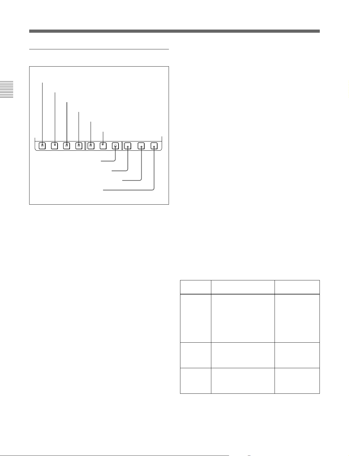
!¡ Time code setting section
TC switch and indicators
INT/EXT switch and indicators
PRESET/REGEN switch and indicators
PRESET
REGEN
TC GENERATOR
FREE
RUN
REC
RUN
DF
NDF
VITC
ON
LTC
AUTO
VITC
TC
INT
EXT
INT/EXT (internal/external) switch and indicators
This switch selects the time code used:
INT: The time code produced by the internal time
code generator.
EXT: The external time code selected as follows.
•When the TC switch is set to LTC or AUTO
The external time code input to the TIME CODE
IN connector.
•When the TC switch is set to VITC
The VITC time code included in the input video
signal.
PRESET/REGEN (preset/regenerated) switch and
indicators
This switch makes the following selection for the
internal time code generator:
PRESET: The initial value of the time code
produced by the internal time code generator can
be preset by a control panel operation or by
remote control from a device connected to the
REMOTE1-IN(9P) connector.
REGEN: The internal time code generator is
synchronized to the playback time code read by
the internal time code reader.
The indicator corresponding to the selection lights.
Chapter 2 Location and Function of Parts
FREE RUN/REC RUN switch and
indicators
DF/NDF switch and indicators
VITC switch and indicator
FREE RUN/REC RUN switch and indicators
This switch selects the time code run mode of the
internal time code generator.
FREE RUN: Regardless of the operating mode of
this unit, the time code value advances
continuously while the power is on.
TC (time code) switch and indicators
This switch selects the time code displayed in the
1)
lower control panel in the sequence: LTC
2)
n VITC
. The indicator corresponding to the
n AUTO
selection lights.
REC RUN: The time code value advances only
during recording. When this mode is selected, set
the INT/EXT switch to INT, and the PRESET/
REGEN switch to PRESET.
The indicator corresponding to the selection lights.
When AUTO is selected, the time code displayed is
VITC when the tape transport speed is up to halfspeed, and LTC when it is more than half-speed.
..........................................................................................................................................................................................................
1) LTC: abbreviation of Longitudinal Time code. This time
code is recorded on a longitudinal track on the tape.
Reading is unreliable at low speeds, and not possible at
all during still playback.
2) VITC: abbreviation of Vertical Interval Time code. This
is inserted in the vertical blanking interval and recorded
on the video tracks. It can be read at low speeds and
during still playback, but not during high-speed
playback.
Chapter 2 Location and Function of Parts 2-5

2-1 Control Panels
DF/NDF (drop-frame/non-drop-frame) switch and
indicators
In a 525/60 system, this switch selects the mode of
advancing the time code generator and CTL counter.
DF: Drop-frame mode.
NDF: Non-drop-frame mode.
Chapter 2 Location and Function of Parts
The indicator corresponding to the selection lights.
Note
When the PRESET/REGEN switch is set to REGEN,
since the time code generator is synchronized to the
playback time code, this switch has no effect.
VITC switch and indicator
To record the time code produced by the internal time
code generator as a VITC, press this switch, lighting
the ON indicator.
When the ON indicator is off, internally generated
time code is not recorded as VITC, but VITC present
in the input video signal is recorded unchanged.
1)
1)
!™ REMOTE buttons and RS-232C indicator
Press one of these buttons to select the device
controlling this unit.
1(9P): This unit is controlled by the device connected
to the REMOTE1-IN(9P) or REMOTE1-OUT(9P)
connector. The button lights.
2(50P): This unit is controlled by the device
connected to the REMOTE PARALLEL I/O(50P)
connector. The button lights.
RS-232C indicator: This indicator lights when this
unit is controlled through the RS-232C connector.
..........................................................................................................................................................................................................
1) Drop-frame/non-drop-frame mode:
In the NTSC system, the actual frame rate is 29.97
frames per second. There is therefore a cumulative
discrepancy between the actual frame rate and the 30
frames per second rate on which time code is based. In
drop-frame mode, except once every 10 minutes, the first
two frames are skipped at the beginning of each minute
to keep the time code values in step with actual elapsed
time.
In non-drop-frame mode, the correction is not carried
out, and there is a discrepancy of about 86 seconds per
day between actual elapsed time and time code values.
2-6 Chapter 2 Location and Function of Parts
2-1-2 Lower Control Panel
1 Editing mode setting section
2 Monitor/menu/display setting section
ASSEMBLE
DMC EDIT
FEED
PREVIEW
INSERT
VIDEO TIME CODE
CH-1
CH-2 CH-3 CH-4
MEMORY
AUTO EDIT
DELETE
REVIEW
TRIM
–
AUDIO
IN OUT
ENTRY
IN
+
OUT
4 Editing control section 5 Shot mark section
1 Editing mode setting section
1 ASSEMBLE button
ASSEMBLE
2 VIDEO button
INSERT
VIDEO TIME CODE
3 TIME CODE button
VI TC UB
GOOD SHOT
MARK
ERASE
LIST
3 Display section
CAPSTAN
0
LOCK
TCG TOTAL REMAIN 525 625
A OUT
REC
A IN DF LTC VITC 8F 4F 2F
PB EECONFIPREREAD PB MENU SET HOLD
STANDBY PREROLL
REC/
EJECT REW PLAY F FWD STOP
6
6 Tape transport control section
RECORDER
JOG
REVERSE
SHUTTLE JOG VAR
FORWARD
CH
CONDITION
9
CONFI ON
CTL/TC/UB TOTAL/REMAIN
EDIT
)
EVENT
REC
p
ALARM
INHIBIT
SERVO
BETACAM SX
DOLBY
NR
PLAYER
%
RESET
SHUTTLE/
VAR
KEY
7 Search control section
2 VIDEO button
2)
To select the video signal for insert editing
, press this
button, turning it on.
3 TIME CODE button
To select time code for insert editing, press this button,
turning it on.
Chapter 2 Location and Function of Parts
4 CH-1 to CH-4 (channel 1 to channel 4) buttons
CH-1
CH-2 CH-3 CH-4
For insert editing, to select audio channels 1 to 4, press
these buttons, turning them on. You can select any
number of the channels.
4 CH-1 to CH-4 buttons
1 ASSEMBLE button
Press this button, turning it on, to carry out assemble
1)
editing
.
All signals (video signals, audio signals, time code
signals, and so forth) are recorded together.
..........................................................................................................................................................................................................
1) Assemble editing: Editing in which new video/audio is
added in sequence to the end of existing recorded video/
audio.
2) Insert editing: Editing in which new video/audio is added
into the middle of existing recorded video/audio.
Chapter 2 Location and Function of Parts 2-7
2-1 Control Panels
2 Monitor/menu/display setting section
1 PREREAD button
2 CONFI button
Chapter 2 Location and Function of Parts
PB EEPREREAD CONFI PB MENU SET HOLD
1 PREREAD button
When this is lit, a preread (read-before-write) is carried
out in insert editing.
2 CONFI (confidence) button
When this is lit, the CONFI indicator appears in the
display, and during recording the video and audio
signals are simultaneously played back by the specialpurpose confidence heads. This enables you to check
the signals being recorded.
3 PB.EE (playback E-E) button
To select E-E mode input signals for the video/audio
signals output during fast forward, rewind, still, and
standby, press this button, turning it on.
Either one of this button and the PB button 4 is
always lit.
4 PB (playback) button
To select playback signals for the video/audio signals
output during fast forward, rewind, still, and standby,
press this button, turning it on.
Either one of this button and the PB.EE button 3 is
always lit.
3 PB.EE button
4 PB button
5 MENU button
6 SET button
7 HOLD button
8 CTL/TC/UB button
9 TOTAL/REMAIN button
0 RESET button
CTL/TC/UB TOTAL/REMAIN
RESET
5 MENU button
Use this button for setup menu operations.
Pressing this button, turning it on, displays setup
menus in the fluorescent display of the display section
3. Press the button once more to exit from the menu
display.
For details of setup menu operations, see Chapter 7, “Menu
System”.
6 SET button
Use this button for setting time code and user bit
values and in setup menu operations.
For details of setup menu operations see Chapter 7, “Menu
System”, and for details of setting time code and user bit
values see Section 4-1-2, “Recording Time Code and User
Bit Values” (page 4-2).
7 HOLD button
To stop updating of the time code or user bit value in
the fluorescent display (that is, to hold the display),
press this button, turning it on. To set a time code or
user bit value, first press this button to hold the value.
8 CTL/TC/UB button
This selects the value displayed in the fluorescent
display in the following sequence: CTL, TC, UB.
As the display changes, the corresponding indicators
over the fluorescent display also show the status.
Time code display value selection and display contents
Display
selection
CTL Tape running time (hours,
TC Playback time code read
UB The UB indicator
a) The selection of LTC or VITC is made by the TC switch.
When VITC is selected, the VITC indicator over the TC
switch lights.
Value displayed Indicator status
minutes, seconds,
frames) computed from
the CTL (control) signal
recorded on the tape
during playback, or a
count of the CTL signal
pulses during recording.
by the internal time code
reader or time code
during recording.
User bit value inserted in
the playback time code or
time code during
recording.
a)
a)
TC and UB
indicators are
both off.
The TC indicator
lights and the UB
indicator goes off.
lights and the TC
indicator goes off.
2-8 Chapter 2 Location and Function of Parts
9 TOTAL/REMAIN button
Press this button to switch between a TOTAL
indication or REMAIN (remaining) indication on the
fluorescent display. According to the selection, the
TOTAL indicator or REMAIN indicator above the
fluorescent display lights.
0 RESET button
To reset a CTL, time code (TC) or user bit (UB) value
displayed in the fluorescent display, hold this button
down.
Resetting the CTL value erases all edit points.
For details of the TOTAL or REMAIN indicators, see the
next page.
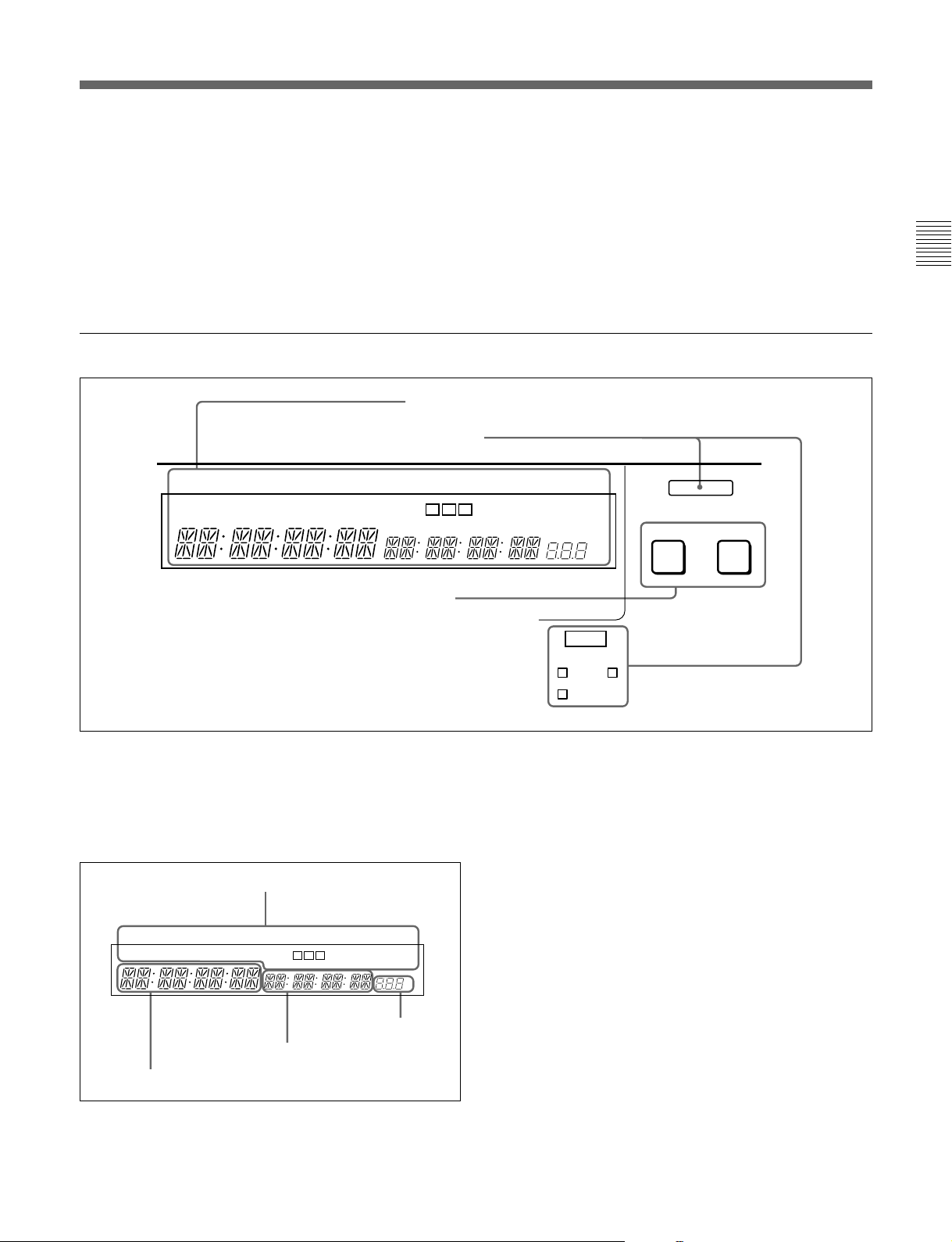
3 Display section
1 Fluorescent display and indicators
2 Indicators
CAPSTAN
LOCK
VI TC UB
3 PLAYER button and RECORDER button
A IN DF LTC VITC 8F 4F 2F
A OUT
TCG TOTAL REMAIN 525 625
CH
CONDITION
CONFI ON
EVENT
REC
DOLBY
NR
%
ALARM
INHIBIT
SERVO
KEY
BETACAM SX
PLAYER
Chapter 2 Location and Function of Parts
RECORDER
1 Fluorescent display and indicators
This comprises a time data display area 1, a time data
display area 2, and a speed display area provided by
the fluorescent display, and also a number of
indicators.
Indicator area
CAPSTAN
CH
LOCK
VI TC UB
A IN DF LTC VITC 8F 4F 2F
Time data display area 1
Time data display area 2
CONDITION
TCG TOTAL REMAIN 525 625
A OUT
CONFI ON
EVENT
DOLBY
NR
%
Speed display area
Time data display area 1
Normally this displays a CTL count, time code value,
or user bit value according to the setting of the CTL/
TC/UB button in the monitor/menu/display setting
section 2 and the setting of the TC switch in the
upper control panel.
It is also used to display an IN point (or audio IN
point), a duration, error messages, setup menus, and so
forth.
For details of the selection of CTL count, time code value,
or user bit value see the description of the CTL/TC/UB
button (previous page).
Chapter 2 Location and Function of Parts 2-9

2-1 Control Panels
Time data display area 2
This shows a TOTAL time indication or REMAIN
(remaining) time indication according to the setting of
the TOTAL/REMAIN button in the monitor/menu/
display setting section 2. Depending on the display,
the corresponding one of the TOTAL and REMAIN
Chapter 2 Location and Function of Parts
indicators immediately above lights.
TOTAL: Time value representing the total tape
length.
REMAIN: Time value representing the remaining
tape length.
These are approximate values calculated on the basis
of the detected tape diameter. They are not precise to
units of seconds.
When no cassette has been loaded or the loaded
cassette has not started running, or when the remaining
tape length has not yet been calculated because the
tape started running only seconds before, “---------”
appears as the TOTAL/REMAIN indication.
This area is also used to display an OUT point (or
audio OUT point), a time code value produced by the
time code generator, a duration, error messages, setup
menus, and so forth.
Speed display area
This displays the speed during feed or tape speed
override play.
Indicator area
This includes the following indicators.
• VI (VITC) indicator: When a VITC time code
value or VITC user bit value is displayed in the
time data display area 1, this indicator lights
together with the TC or UB indicator.
• TC (time code) indicator: This lights when a time
code is displayed in the time data display area 1.
• UB (user bits) indicator: This lights when a user
bit value is displayed in the time data display area
1.
• A (audio) IN indicator: When an IN point is
displayed in time data display area 1, the IN
indicator lights, and when an audio IN point is
displayed, the A indicator lights in addition to the
IN indicator.
..........................................................................................................................................................................................................
1) CONFI playback: This refers to playback of the audio
and video signals immediately after recording, using the
confidence heads, the signal being output to all intents
and purposes simultaneously with recording. This is used
to check recording.
• DF (drop-frame) indicator: This lights when a
displayed time code value is in drop-frame mode.
• LTC, VITC indicators: Regardless of the display
in the time data display area 1, these indicators
light when the corresponding time code values are
being read or recorded (during recording).
• CAPSTAN LOCK 8F/4F/2F (8 fields/4 fields/2
fields) indicators: The indicator lights
corresponding to the mode selected by the
CAPSTAN LOCK switch on the subsidiary
control panel or in setup menu item 106.
• CH (channel) CONDITION indicator: A threecolor indicator shows the state of the playback
signal.
Green: The state of the playback signal is good.
Yellow: The playback signal is somewhat
deteriorated, but playback is possible.
Red: The playback signal is deteriorated.
When this indicator remains on, head cleaning
or an internal inspection is necessary.
• CONFI (confidence) ON indicator: This indicates
1)
the state of the VTR CONFI playback
function.
When the CONFI playback function is enabled,
the CONFI indicator lights, and when CONFI
playback is actually being carried out the ON
indicator also lights.
CONFI playback settings are carried out using the
CONFI button.
• A (audio) OUT indicator: When an OUT point is
displayed in time data display area 2, the OUT
indicator lights, and when an audio OUT point is
displayed, the A indicator lights in addition to the
OUT indicator.
• TCG (time code generator) indicator: This lights
when a time code generated by the internal time
code generator is displayed in the time data
display area 2.
• TOTAL, REMAIN indicators: When the
“TOTAL” time is displayed in time data display
area 2 the TOTAL indicator lights, and when the
“REMAIN” time is displayed in time data display
area 2 the REMAIN indicator lights.
2-10 Chapter 2 Location and Function of Parts
• 525, 625: The indicator showing the number of scan
lines for the television standard selected using
basic menu item 013 lights (NTSC: 525 scan
lines, field frequency 60 Hz; PAL: 625 scan lines,
field frequency 50 Hz).
• DOLBY NR indicator: This lights when the Dolby
1)
noise-reduction
circuit is functioning.
2 Indicators
REC
ALARM
INHIBIT
SERVO
KEY
BETACAM SX
PLAYER
RECORDER
ALARM indicator
KEY INHIBIT indicator
SERVO indicator
REC INHIBIT indicator
BETACAM SX indicator
BETACAM SX indicator
When recording in Betacam SX format or playing
back a tape recorded in Betacam SX format, this
indicator lights.
ALARM indicator
This lights when a hardware error is detected on the
unit, and goes off when the error is resolved.
When this indicator is lit, an error message appears in
the fluorescent display. If you are using the SDI
OUTPUT 3 (SUPER) or COMPOSITE VIDEO
OUTPUT 3 (SUPER) connector, then when the
CHARACTER switch in the subsidiary control panel
is set to ON, the error message also appears on the
monitor screen.
REC (recording) INHIBIT indicator
This indicator is on or off according to the
combination of the setting of the REC INHIBIT switch
on the subsidiary control panel and the record inhibit
plug on the cassette, as shown in the following table.
When this indicator is on, recording on tape is
prohibited.
REC INHIBIT indicator indications
REC INHIBIT
switch position
ON Record inhibit/permit Lit
OFF Record inhibit Lit
State of the record inhibit
plug on the cassette
Record permit Off
REC INHIBIT
indicator state
a)
a) It is possible to make a setting (extended menu item 107)
so that in this case the indicator flashes.
3 PLAYER button and RECORDER button
When you carry out editing using a VTR connected to
the REMOTE 1-IN(9P) or REMOTE 1-OUT(9P)
connector as the player and this unit as the recorder,
these buttons select which VTR tape transport
operations apply to.
PLAYER: The editing control buttons and tape
transport buttons on this unit control the external
player VTR.
RECORDER: The editing control buttons and tape
transport buttons on this unit control the recorder,
that is to say, this unit.
When this unit is being used in standalone mode,
neither button functions.
Chapter 2 Location and Function of Parts
KEY INHIBIT indicator
This indicator lights when the KEY INHIBIT switch
on the subsidiary control panel is set to ON.
SERVO indicator
When the drum servo and capstan servo are locked
2)
,
this indicator lights.
..........................................................................................................................................................................................................
1) Dolby noise-reduction: Dolby noise reduction
manufactured under license from Dolby Laboratories
Licensing Corporation. “DOLBY” and the double-D
symbol a are trademarks of Dolby Laboratories
Licensing Corporation.
2) Servo lock: This refers to the synchronization of the
phase of the drum rotation and the reference signal for
the tape transport position, so that the video heads can
trace the same pattern on the tape for playback or
recording.
Chapter 2 Location and Function of Parts 2-11
2-1 Control Panels
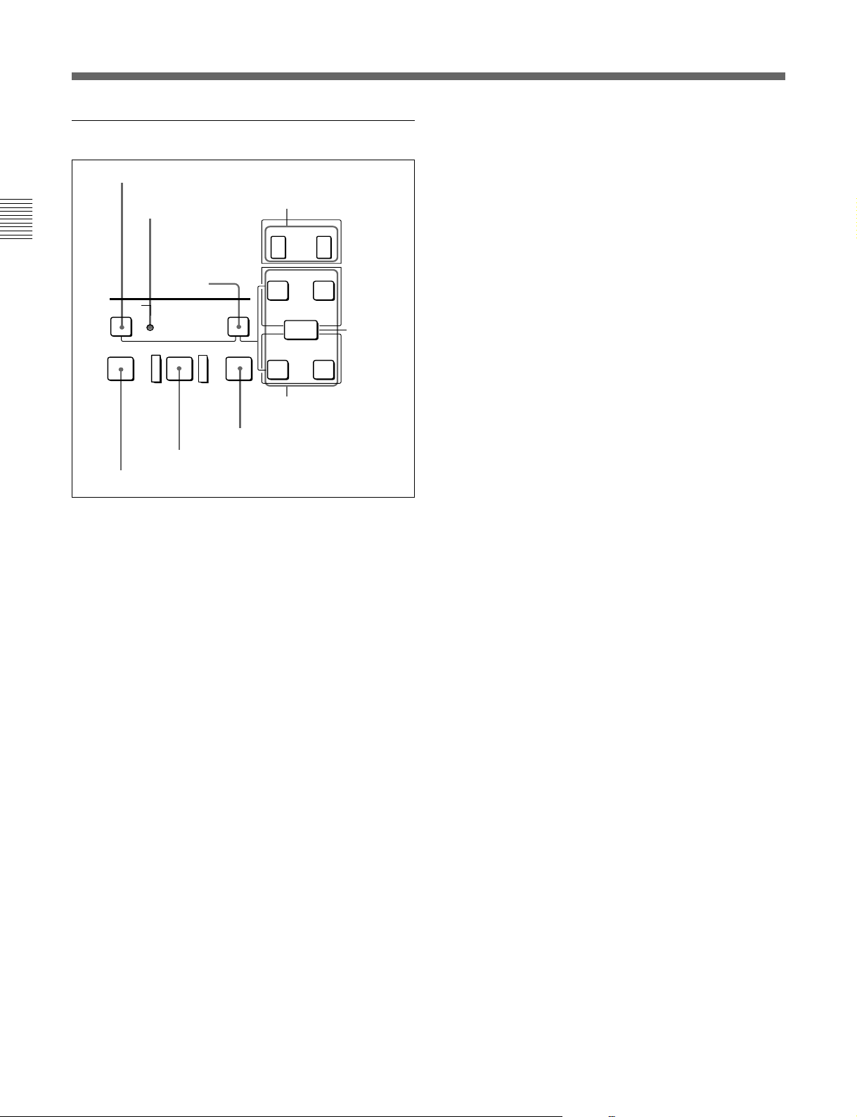
4 Editing control section
1 DMC EDIT/FEED button
2 MEMORY indicator
Chapter 2 Location and Function of Parts
3 DELETE
DMC EDIT
FEED
MEMORY
PREVIEW
5 PREVIEW button
1 DMC EDIT/FEED button
Press this button to carry out recording of playback at
any speed between –1 and +2 times normal, automatic
playback, and automatic editing.
For playback in feed mode, hold down this button and
press the PLAY button.
Playback in feed mode requires a setting of extended
menu item 111.
button
DELETE
AUTO EDIT
6 AUTO EDIT button
REVIEW
7 REVIEW button
4 TRIM buttons
TRIM
–
IN OUT
IN
+
AUDIO
ENTRY
OUT
8 Edit point setting
buttons
Hold down the IN, OUT, AUDIO IN, or AUDIO OUT
button, and press one of these buttons. The + button
advances the corresponding edit point by one frame,
and the – button sets it back by one frame.
Pressing one of these buttons while holding down the
PLAY button adjusts the tape speed by +8% or –8%
correspondingly. (Capstan override function)
5 PREVIEW button
After edit point setting, to preview the editing results
on the monitor before recording, press this button,
turning it on.
If the IN point is not set, the preview is carried out
with the point where you pressed this button as the IN
point.
During the preview it is lit, and when the preview ends
it flashes.
6 AUTO (automatic) EDIT button
After edit point setting, to carry out automatic editing
(recording), press this button, turning it on.
If the IN point is not set, the automatic editing is
carried out with the point where you pressed this
button as the IN point.
If you pressed the PREVIEW button to carry out a
preview, when the preview ends it flashes.
7 REVIEW button
Use this button to carry out a review of the editing
results after carrying out automatic editing.
2 MEMORY indicator
When memorizing the playback speed using the DMC
EDIT button, this indicator flashes as the playback
speed is captured to memory, and lights continuously
once the speed is captured.
3 DELETE button
This deletes an existing edit point.
Hold down this button and press the IN, OUT, AUDIO
IN, or AUDIO OUT button which is lit, indicating an
existing edit point, to delete the corresponding edit
point. The button either goes off or flashes. When the
button flashes, it is necessary to set the deleted edit
point again.
4 TRIM buttons
Use these buttons to trim an edit point, once set, to
single-frame precision.
2-12 Chapter 2 Location and Function of Parts
8 Edit point setting buttons
AUDIO IN button and AUDIO OUT button
In insert editing, to set an audio IN point or audio OUT
point separate from the corresponding video edit point,
hold down the AUDIO IN button or AUDIO OUT
button, and press the ENTRY button.
After you have made the setting, pressing the AUDIO
IN button or AUDIO OUT button displays the audio
IN point or audio OUT point set on the fluorescent
display.
IN button and OUT button
To set a video IN point or OUT point, hold down the
IN button or OUT button, and press the ENTRY
button.
After you have made the setting, pressing the IN
button or OUT button displays the IN point or OUT
point set on the fluorescent display.

ENTRY button
Use this for setting edit points and so forth.
•To set a video IN point or OUT point: Hold down
the IN button or OUT button, and press this button.
•To set an audio IN point or OUT point: Hold down
the AUDIO IN button or AUDIO OUT button, and
press this button.
5 Shot mark section
6 Tape transport control section
1 STANDBY button
2 PREROLL button
3 REC button
4 EDIT button
REC
STANDBY PREROLL
EDIT
Chapter 2 Location and Function of Parts
When using a tape with shot markers recorded, you
can read out the good shot marks from the tape, by
simultaneously pressing the LIST button and either F
FWD button or REW button.
GOOD SHOT
MARK
REC/
LIST
ERASE
3 REC/ERASE indicator
1 MARK button
2 LIST button
1 MARK button
Hold this button down for 2 seconds or more, to enable
writing, amending, and deleting of shot marks.
2 LIST button
Use this button to read in and list shot marks.
3 REC/ERASE indicator
This lights in the state in which writing, amending, and
deleting of shot marks is enabled.
EJECT REW PLAY F FWD STOP
6
0
8 REW button
9 EJECT button
7 PLAY button
)
9
6 F FWD button
p
5 STOP button
1 STANDBY button
When a cassette is inserted and this button is off, to put
the VTR in standby mode, press the button, turning it
on.
In standby mode, the drum is rotating and the tape is in
contact with the drum. As a result, recording or
playback can start immediately.
To end standby mode, press the STANDBY button,
turning it off.
If 8 minutes (value can be varied using extended menu
item 501) elapse in standby mode, the unit
automatically switches out of standby mode to protect
the tape.
2 PREROLL button
Press this button to cue up to the preroll point (before
the IN point by the time set as the preroll time) on the
tape. You can change or select the preroll time and the
1)
state of the unit at the end of preroll (“stop mode”
or
still playback mode) using basic menu item 001 or
extended menu item 401.
Cuing up edit points
Hold down the IN, OUT, AUDIO IN, or AUDIO OUT
button while pressing this button to cue up to the
corresponding edit point.
..........................................................................................................................................................................................................
1) Stop mode: the state in which the device currently the
subject of operation is stopped, and the STOP button is
lit.
Chapter 2 Location and Function of Parts 2-13
2-1 Control Panels
3 REC (record) button
To start recording, press this button together with the
PLAY button, turning it on.
Monitoring in E-E mode
When the unit is in stop mode, when you press this
Chapter 2 Location and Function of Parts
button it lights, and you can monitor the video and
audio in E-E mode. To return to the original state,
press the STOP button.
During playback, search, fast forward, or rewind,
while this button is held down you can monitor the
video and audio in E-E mode. In this case the button
does not light.
4 EDIT button
To carry out manual editing, press this button
simultaneously with the PLAY button.
Monitoring in E-E mode
When the unit is in stop mode, when you press this
button it lights, and you can monitor the input signal
selected with the ASSEMBLE button or INSERT
button in E-E mode. To return to the original state,
press the STOP button. During playback, search, fast
forward, or rewind, while this button is held down you
can monitor the video in E-E mode.
5 STOP button
To stop recording or playback, press this button,
turning it on.
When you stop playback, the unit switches either to
still playback or to E-E mode according to setup menu
settings, and the settings of the PB.EE button and PB
button.
7 PLAY button
To start playback, press this button, turning it on.
To operate in capstan override mode
Hold down this button, and turn the search dial.
For details of capstan override mode, see the item relating
to the search dial in the next page.
8 REW (rewind) button
To rewind the tape, press this button, turning it on.
9 EJECT button
To eject the cassette, press this button. While the
cassette is being ejected, this button lights.
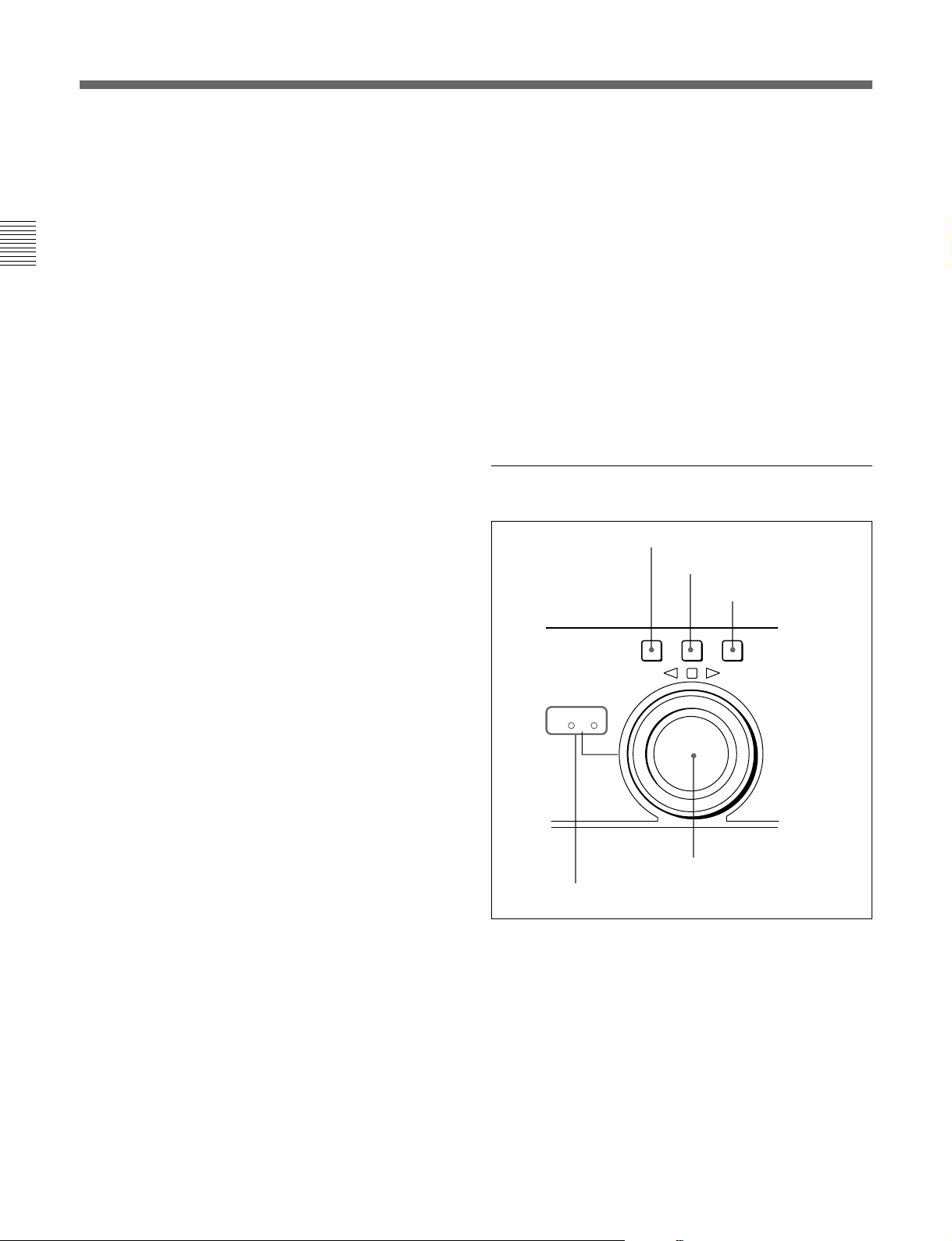
7 Search control section
1 SHUTTLE button
2 JOG button
3 VAR button
SHUTTLE JOG VAR
FORWARD
SHUTTLE/
REVERSE
VAR
JOG
Fault display function
This flashes in the following cases related to reference
signals:
•When the OUT REF switch on the subsidiary control
panel is set to INPUT VIDEO, and there is no input
video signal.
•When the OUT REF switch on the subsidiary control
panel is set to REF, and there is no external reference
signal input or the input external reference signal is
not synchronized to the input video signal.
6 F FWD (fast forward) button
To fast forward the tape, press this button, turning it
on.
2-14 Chapter 2 Location and Function of Parts
4 Search dial
5 SHUTTLE/VAR and JOG indicators
1 SHUTTLE button
To use the search dial for playback in shuttle mode,
press this button, turning it on.
For details of playback in shuttle mode, see the item for the
search dial 4.

2 JOG button
To use the search dial for playback in jog mode, press
this button, turning it on.
For details of playback in jog mode, see the item for the
search dial 4.
3 VAR (variable) button
To use the search dial for playback in variable speed
mode, press this button, turning it on.
For details of playback in variable mode, see the item for
the search dial 4.
4 Search dial
Turn this to carry out playback in the modes shown in
the following table. Turning the dial clockwise lights
the · indicator and plays back in the forward
direction. Turning the dial counterclockwise lights the
ª indicator and plays back in the reverse direction.
When the tape is stopped, the π indicator lights.
Pressing the dial toggles between shuttle and jog
modes or between variable and jog modes.
You can carry out noiseless playback in the range of
–1 times to +2 times normal speed when using a
Betacam SX format tape.
Playback modes using the search dial
Playback mode Operations and functions
Shuttle
Jog Press the JOG button or the search dial
Variable speed Press the VAR button, turning it on,
Capstan override Hold down the PLAY button and turn
Press the SHUTTLE button or the
search dial so that the SHUTTLE
button lights, then turn the search dial.
Playback is carried out at a speed
determined by the position of the
search dial. The playback speed range
is as follows:
• Using a Betacam SX tape: –78 to +78
times normal speed
• Using an analog Betacam tape: –35
to +35 times normal speed for DNWA75 or –42 to +42 times normal speed
for DNW-A75P
The search dial has detents at the still
position and at ±5 times normal speed.
The maximum shuttle mode playback
speed can be changed by changing the
setting of item 102 in the extended
menu (see page 7-9).
so that the JOG button lights, then turn
the search dial. Playback is carried out
at a speed determined by the speed of
rotation of the search dial. The
playback speed range is –1 to +1 time
normal speed:
The search dial has no detents.
then turn the search dial. You can
control the playback speed finely (51
steps) in the range of –1 times to +2
times normal speed.
The search dial has detents at the still
position and at the normal speed
position.
the search dial to adjust the playback
speed in the range of ±15%. Use this
for phase adjustment between this unit
and an external connected device.
Chapter 2 Location and Function of Parts
Changing the setting of extended menu item 101 enables you
to use the search dial alone to select shuttle/jog/variable
speed modes, without using the SHUTTLE, JOG, and VAR
buttons.
5 SHUTTLE/VAR and JOG indicators
When searching in shuttle mode, the SHUTTLE/VAR
indicator lights, and when searching in jog mode, the
JOG indicator lights.
Chapter 2 Location and Function of Parts 2-15
2-1 Control Panels
2-1-3 Subsidiary Control Panel
Pull out the lower control panel to reveal the
subsidiary control panel.
Chapter 2 Location and Function of Parts
1 CONTROL PANEL switch
2 CHARACTER switch
CONTROL
CHARACTER DOLBY
PANEL
EXT INT OFF ON OFF ON
3 DOLBY NR switch
4 OUT REF switch
5 PROCESS CONTROL switch
OUT REF
NR
INPUT
VIDEO
PROCESS
CONTROL
REF REMOTE LOCAL
MENU
!∞ CAPSTAN LOCK switch
!¢ KEY INHIBIT switch
!£ REC INHIBIT switch
!™ SC knob
!¡ SYNC knob
VIDEO
CHROMA SET UP Y/C DELAY CHROMA PHASE SYNC SC
PRESET
MANUAL
PRESET
MANUAL
PRESET
MANUAL
PRESET
MANUAL
PRESET
MANUAL
SYSTEM PHASE
0
CHROMA PHASE knob and PRESET/MANUAL switch
9 Y/C DELAY knob and PRESET/MANUAL switch
8 SET UP (DNW-A75)/BLACK LEVEL (DNW-A75P) knob and
PRESET/MANUAL switch
7 CHROMA knob and PRESET/MANUAL switch
6 VIDEO knob and PRESET/MANUAL switch
REC
INHIBIT
ON OFF ON OFF 2FD 8FD
KEY
INHIBIT
CAPSTAN
LOCK
4FD
(625/50)
1 CONTROL PANEL switch
Select the state of the control panel when this unit is
operated.
INT: When operating this unit by its own control
panel.
EXT: When the control panel is detached, to operate
this unit remotely by a connection to the
CONTROL PANEL connector.
The factory default setting is INT.
2 CHARACTER switch
Select whether or not to superimpose text information
such as time code, menu settings, and alarm messages
on the video signal output from the COMPOSITE
VIDEO OUTPUT 3 (SUPER) connector and SDI
OUTPUT 3 (SUPER) connector.
ON: Superimposed text.
OFF: No superimposed text.
The factory default setting is ON.
2-16 Chapter 2 Location and Function of Parts
3 DOLBY NR (noise reduction) switch
When using an oxide tape, switch the Dolby noisereduction system for analog audio on or off.
When using metal tape, the Dolby noise-reduction
system is automatically switched on, regardless of the
setting of this switch.
ON: Enable the Dolby noise-reduction system for
playback of an analog Betacam oxide tape.
OFF: Disable the Dolby noise-reduction system for
playback of an analog Betacam oxide tape.
The factory default setting is OFF.

4 OUT REF (reference) switch
This switch selects the reference signal for this unit
depending on the combination of the setting of
extended menu item 309 and the operating state of the
unit.
REF: Use the signal input to the REF. VIDEO
INPUT connector as the reference signal. During
recording input digital audio and video signals
must be synchronized with this signal.
INPUT VIDEO: Use the input video signal selected
by the VIDEO INPUT SELECT switch as the
reference signal.
7 CHROMA (chrominance) knob and PRESET/
MANUAL switch
The switch makes the selection described immediately
below. When it is set to MANUAL, you can use the
knob to adjust the chrominance signal output level.
PRESET: Regardless of the position of the knob, the
chrominance signal output level is set to the
reference value.
MANUAL: You can adjust the chrominance signal
output level in the range ±3 dB.
You can change the adjustment range using
extended menu item 714.
Chapter 2 Location and Function of Parts
Note
Operating this switch during playback may cause a
momentary interruption of the playback sound.
5 PROCESS CONTROL switch
This selects the method of control of the internal
digital video processor.
REMOTE: Select this position to use an optional
BVR-50/50P Remote Control Unit for remote
control of the internal digital video processor.
MENU: Select this position to use setup menus to
change the settings for the internal digital video
processor.
LOCAL: Select this position to use the subsidiary
control panel to change the settings for the internal
digital video processor.
6 VIDEO knob and PRESET/MANUAL switch
The switch makes the selection described immediately
below. When it is set to MANUAL, you can use the
knob to adjust the video signal output level.
PRESET: Regardless of the position of the knob, the
video signal output level is set to the reference
value.
MANUAL: You can adjust the video signal output
level in the range ±3 dB.
You can change the adjustment range using
extended menu item 714.
8 SET UP (DNW-A75)/BLACK LEVEL (DNWA75P) knob and PRESET/MANUAL switch
The switch makes the selection described immediately
below. When it is set to MANUAL, you can use the
knob to adjust the (black) setup level (525/60 system)
or black level (625/50 system).
PRESET: Regardless of the position of the knob, the
setup level (525/60 system) or black level (625/50
system) is set to the reference value.
MANUAL: You can adjust the setup level (525/60
1)
system) in the range ±30 IRE
, or the black level
(625/50 system) in the range ±210 mV.
9 Y/C DELAY knob and PRESET/MANUAL
switch
The switch is effective only for playback of video
recorded in Betacam or Betacam SP format. It makes
the selection described immediately below. When it is
set to MANUAL, you can use the knob to adjust the
Y/C delay.
PRESET: Regardless of the position of the knob, the
Y/C delay is set to the reference value.
MANUAL: You can adjust the Y/C delay in the
range ±100 ns.
..........................................................................................................................................................................................................
1) IRE: A unit for representing a video level laid down by
the IRE (Institute of Radio Engineers). The IRE is now
the IEEE (Institute of Electrical and Electronic
Engineers).
Chapter 2 Location and Function of Parts 2-17

2-1 Control Panels
0 CHROMA (chrominance) PHASE knob and
PRESET/MANUAL switch
The switch makes the selection described immediately
below. When it is set to MANUAL, you can use the
knob to adjust the chrominance phase (the phase
difference from a burst signal).
Chapter 2 Location and Function of Parts
PRESET: Regardless of the position of the knob, the
chrominance phase is set to the reference value.
MANUAL: You can adjust the chrominance phase in
the range ±30˚.
!¡ SYNC knob
This adjusts the output signal sync phase with respect
to the input reference signal to this unit, in a range of
±15 µs.
Use this adjustment when the output phase of this unit
is not accurately aligned with the reference signal
phase, or when carrying out special effects editing with
this unit and other VTRs connected to a switcher or
other equipment.
!™ SC (subcarrier) knob
This adjusts the output signal subcarrier phase with
respect to the input reference signal to this unit, in a
range of ±200 ns.
For editing with composite signals, use this adjustment
when the output phase of this unit with respect to the
phase of the reference signal is not accurately aligned
with the subcarrier phase. This adjustment does not
affect the output SCH (subcarrier - sync) phase, which
remains constant.
!£ REC (record) INHIBIT switch
When this switch is in the ON position, the REC
INHIBIT indicator in the lower control panel lights,
and recording on tape is no longer possible.
!¢ KEY INHIBIT switch
When this switch is in the ON position, the KEY
INHIBIT indicator in the lower control panel lights,
and the buttons in the upper control panel and lower
control panel specified by the setting of extended
menu item 118 are disabled.
!∞ CAPSTAN LOCK switch
For playback and editing, this switch selects the
capstan lock mode.
For DNW-A75
2FD: The capstan servo locks every two fields.
•There may be a color framing difference between
the tape playback output and the reference signal
selected by the OUT REF switch.
•For assemble editing, there may be a color
framing discontinuity at edit points.
During playback of a tape recorded with a
composite signal as source, there may be a
horizontal shift (H shift) of the image. (When
extended menu item 712 is set to ON.)
4FD: The capstan servo locks every four fields.
•There is no color framing difference between the
tape playback output and the reference signal
selected by the OUT REF switch.
•For assemble editing, color framing continuity at
edit points is assured.
During playback of a tape recorded with a
composite signal as source, no horizontal shift (H
shift) of the image occurs.
Select this position for editing and playback of
composite signals when video phase continuity at
edit points is required, or for A/B roll editing.
8FD (625/50): This position is not normally used in
a 525/60 system.
If you select this position in a 625/50 system, the
tape playback output is subject to virtual color
framing, frame-locked to the reference signal
selected by the OUT REF switch. (This unit is not
subject to color frame locking to the reference
signal.)
For DNW-A75P
2FD/4FD: The capstan servo locks every two fields
(2FD)/four fields (4FD).
•There may be a color framing difference between
the tape playback output and the reference signal
selected by the OUT REF switch.
•For assemble editing, there may be a color
framing discontinuity at edit points.
During playback of a tape recorded with a
composite signal as source, there may be a
horizontal shift (H shift) of the image. (When
extended menu item 712 is set to ON.)
8FD: The capstan servo locks every eight fields.
•There is no color framing difference between the
tape playback output and the reference signal
selected by the OUT REF switch.
•For assemble editing, color framing continuity at
edit points is assured.
During playback of a tape recorded with a
composite signal as source, no horizontal shift (H
shift) of the image occurs.
Select this position for editing and playback of
composite signals when video phase continuity at
edit points is required, or for A/B roll editing.
2-18 Chapter 2 Location and Function of Parts

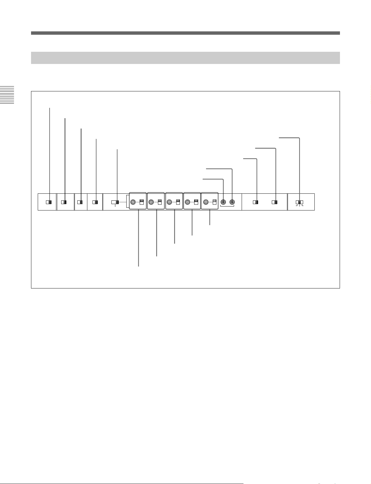
2-2 Connector Panel
BREAKER
Cooling fan
AC IN
1 Analog audio input/output
section
(See page 2-20.)
2 Analog video input/output
section
(See page 2-20.)
LEVEL
LOW HIGH
OFF ON
COMPOSITE
1
2
3
(SUPER)
600Ω
VIDEO OUTPUT
CH4
LOW HIGH
OFF ON
VIDEO INPUT
REF.VIDEO COMPOSITE COMPONENT
75Ω
ON
OFF
CH1
LEVEL
LOW HIGH
OFF ON
600Ω
CH1 CH2 CH3 CH4 R L
AUDIO INPUT
CH2
LEVEL
LOW HIGH
OFF ON
AUDIO OUTPUT
Y
75Ω
ON
R-Y
OFF
B-Y
CH3
600Ω
LEVEL
COMPONENT
Y
R-Y
B-Y
600Ω
3 Digital input/output section
SDI
OUTPUT
INPUT
1
2
3
(SUPER)
TIME CODE
IN OUT
MONITOR OUTPUT
AUDIO INPUT(AES/EBU)
CH1/2 CH3/4
AUDIO OUTPUT(AES/EBU)
CH1/2 CH3/4
(See page 2-21.)
4 Time code input/output section and
audio monitor signal output section
(See page 2-21.)
5 Digital audio input/output section
(See page 2-22.)
Cooling fan
REMOTE 2
PARALLEL I/O(50P)
Chapter 2 Location and Function of Parts
7 Power supply section
(See page 2-23.)
6 External device connectors
RS-232CREMOTE1-OUT(9P)REMOTE1-IN(9P)CONTROL PANEL VIDEO CONTROL
(See page 2-22.)
Chapter 2 Location and Function of Parts 2-19
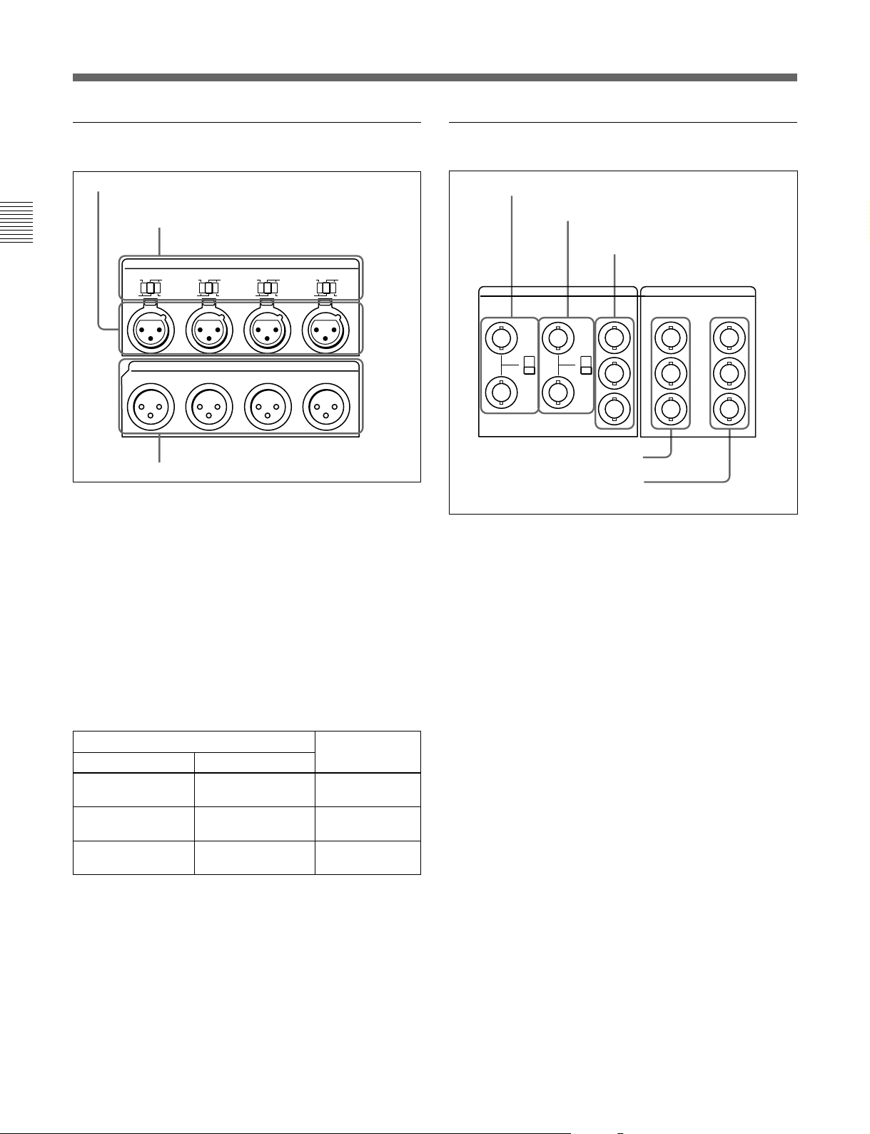
2-2 Connector Panel
1 Analog audio input/output section
1 AUDIO INPUT CH1 to CH4 connectors
2 AUDIO INPUT CH1 to CH4 LEVEL switches
Chapter 2 Location and Function of Parts
CH1
LEVEL
LOW HIGH
OFF ON
CH1 CH2 CH3 CH4
3 AUDIO OUTPUT CH1 to CH4 connectors
1 AUDIO INPUT CH1 to CH4 (channels 1 to 4)
connectors (XLR 3-pin, female)
Input analog audio signals to channels 1 to 4.
2 AUDIO INPUT CH1 to CH4 (channels 1 to 4)
LEVEL switches
Set these for each channel as shown in the following
table, according to the audio input levels to the
AUDIO INPUT CH1 to CH4 connectors and the
impedance.
AUDIO INPUT CH1 to CH4 LEVEL switch settings
Audio input level and impedance Switch setting
Level
–60 dBu
(microphone input)
+4 dBu
(line audio input)
+4 dBm
(line audio input)
3 AUDIO OUTPUT CH1 to CH4 connectors
(XLR 3-pin, male)
These output analog audio signals for channels 1 to 4.
CH2
LEVEL
LOW HIGH
OFF ON
600Ω
AUDIO OUTPUT
Impedance
High impedance
(approx. 20 kΩ)
High impedance
(approx. 20 kΩ)
600 Ω
AUDIO INPUT
CH3
LOW HIGH
OFF ON
600Ω
LEVEL
CH4
LEVEL
LOW HIGH
OFF ON
600Ω
LOW-OFF
(left position)
HIGH-OFF
(center position)
HIGH-ON 600 Ω
(right position)
600Ω
2 Analog video input/output section
1 REF. VIDEO INPUT connectors and 75 Ω
termination switch
2 COMPOSITE VIDEO INPUT connectors
and 75 Ω termination switch
3 COMPONENT VIDEO INPUT
connectors
REF.VIDEO COMPOSITE COMPONENT
VIDEO INPUT
75Ω
ON
OFF
75Ω
ON
OFF
Y
R-Y
B-Y
4 COMPOSITE VIDEO OUTPUT
connectors
5 COMPONENT VIDEO OUTPUT
connectors
1 REF. (reference) VIDEO INPUT connectors
(BNC type) and 75 Ω termination switch
Input a reference video signal. Input a video signal
with chroma burst (VBS) or a monochrome video
signal (VS). When using the loop-through connection
set the switch to the OFF position, and otherwise to the
ON position.
2 COMPOSITE VIDEO INPUT connectors (BNC
type) and 75 Ω termination switch
Input analog composite video signals.
When using the loop-through connection set the switch
to the OFF position, and otherwise to the ON position.
3 COMPONENT VIDEO INPUT connectors
(BNC type)
Input analog component video signals (Y/R–Y/B–Y).
4 COMPOSITE VIDEO OUTPUT connectors
(BNC type)
These output analog composite video signals.
When the CHARACTER switch on the subsidiary
control panel is set to ON, connector 3 (SUPER)
outputs a signal with superimposed time code, menu
settings, alarm messages, and other text information.
COMPOSITE
1
2
3
(SUPER)
VIDEO OUTPUT
COMPONENT
Y
R-Y
B-Y
2-20 Chapter 2 Location and Function of Parts
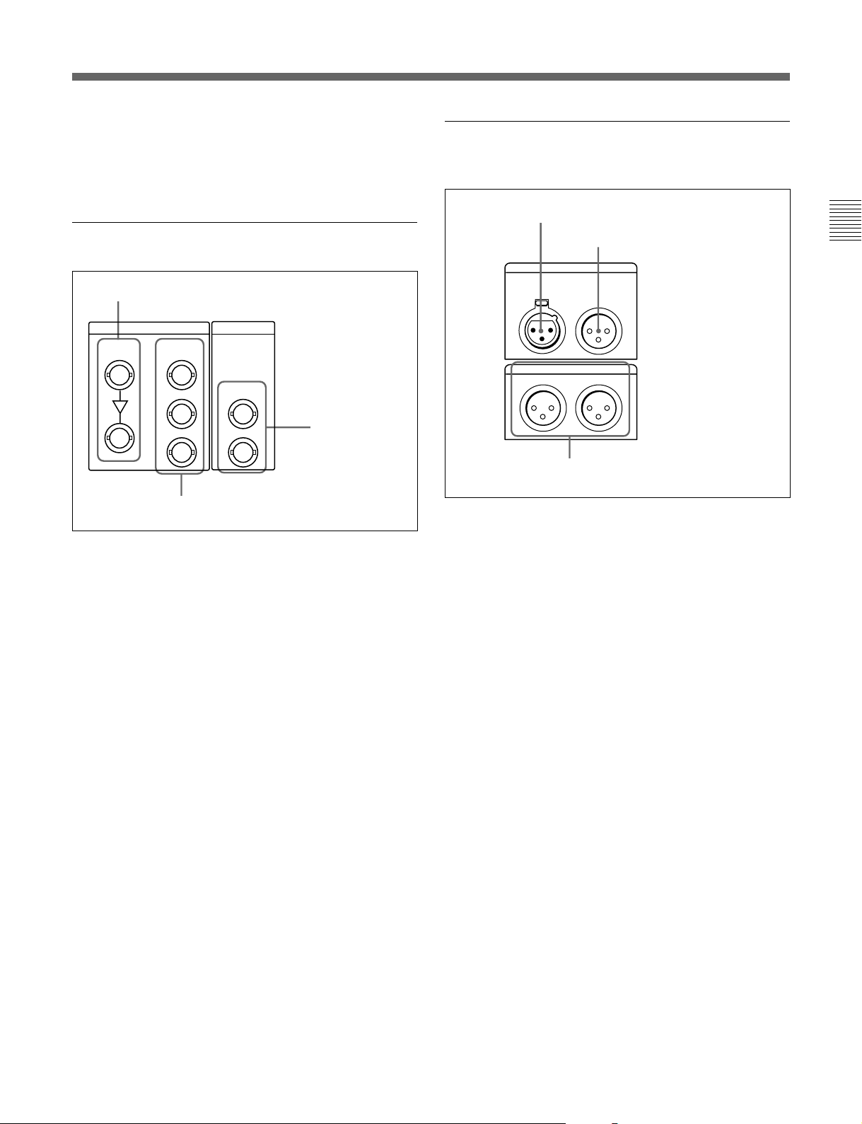
5 COMPONENT VIDEO OUTPUT connectors
TIME CODE
MONITOR OUTPUT
IN OUT
RL
(BNC type)
These output analog component video signals (Y/R–Y/
B–Y).
3 Digital input/output section
1 SDI INPUT connectors
SDI SDTI
INPUT
OUTPUT
1
4 Time code input/output section and
audio monitor signal output section
1 TIME CODE IN connector
2 TIME CODE OUT connector
Chapter 2 Location and Function of Parts
2
3
(SUPER)
2 SDI OUTPUT connectors
OUTPUT
1
2
3 SDTI OUTPUT
connectors
1 SDI (Serial Digital Interface) INPUT connectors
(BNC type)
Input D1 format digital video/audio signals. Of the
two connectors, the upper one is for input, and the
lower one is for a active-through connection.
2 SDI (Serial Digital Interface) OUTPUT
connectors (BNC type)
These output D1 format digital video/audio signals.
When the CHARACTER switch on the subsidiary
control panel is set to ON, connector 3 (SUPER)
outputs a signal with superimposed time code, menu
settings, alarm messages, and other text information.
3 MONITOR OUTPUT connectors
1 TIME CODE IN connector (XLR 3-pin, female)
To record time code from an external device, input a
time code signal from the time code output connector
of the other device.
2 TIME CODE OUT connector (XLR 3-pin, male)
This outputs a time code according to the operating
state of the unit, as follows:
•During playback: the playback time code
By setting extended menu item 606, you can also
output the time code from the internal time code
generator locked to the playback time code.
•During recording: the time code generated by the
internal time code generator or the time code input to
the TIME CODE IN connector.
3 SDTI (Serial Data Transport Interface)
OUTPUT connectors (BNC type)
These output SDTI (SX) video and audio signals.
Using these connectors requires the optional BKNW118 SDTI Output Board.
3 MONITOR OUTPUT connectors (XLR 3-pin,
male)
According to the setting of the audio signal selection
buttons (see page 2-4) on the upper control panel, two
(L and R) audio monitor signals are output.
Chapter 2 Location and Function of Parts 2-21
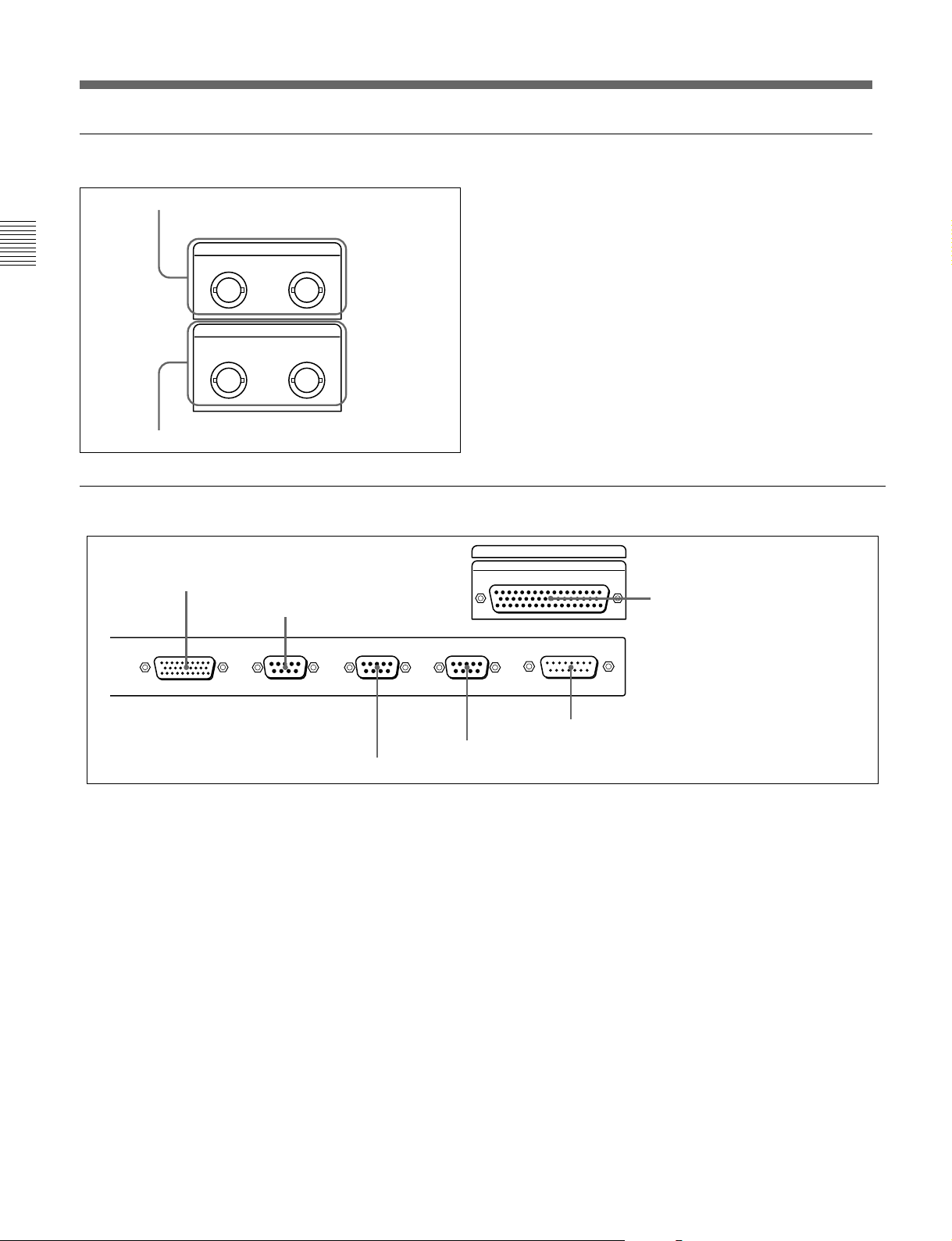
2-2 Connector Panel
5 Digital audio input/output section
1 AUDIO INPUT (AES/EBU) connectors
Chapter 2 Location and Function of Parts
2 AUDIO OUTPUT (AES/EBU) connectors
6 External device connectors
AUDIO INPUT(AES/EBU)
CH1/2 CH3/4
AUDIO OUTPUT(AES/EBU)
CH1/2 CH3/4
1 CONTROL PANEL connector
2 REMOTE1-IN(9P) connector
1 AUDIO INPUT (AES/EBU) connectors (BNC
type)
Input up to two sets (4 channels: channels 1/2 and 3/4)
of AES/EBU format digital audio signals.
2 AUDIO OUTPUT (AES/EBU) connectors (BNC
type)
Output up to two sets (4 channels: channels 1/2 and
3/4) of AES/EBU format digital audio signals.
REMOTE 2
PARALLEL I/O(50P)
6 REMOTE 2 PARALLEL I/O (50P)
connector
RS-232CREMOTE1-OUT(9P)REMOTE1-IN(9P)CONTROL PANEL VIDEO CONTROL
3 REMOTE1-OUT(9P) connector
1 CONTROL PANEL connector (29-pin)
After disconnecting the control panel from this unit,
use this connector to connect the 29-way remote
control cable supplied with the control panel extension
kit.
2 REMOTE1-IN(9P) connector (D-sub 9-pin)
When using this unit together with another DNW-A75/
A75P or a D-1, D-2, or Betacam VTR, and a BVEseries BVE-900/910/2000/9000/9000P/9100/9100P or
other editor, connect the supplied 9-pin remote control
cable from the other unit to this connector. The IN(9P)
and OUT(9P) connectors provide a loop-through
connection for remote control signals.
5 VIDEO CONTROL connector
4 RS-232C connector
3 REMOTE1-OUT(9P) connector (D-sub 9-pin)
This provides the loop-through output for remote
control signals from the REMOTE1-IN(9P) connector
2.
4 RS-232C connector (D-sub 9-pin)
Use this for monitoring and diagnosis of the state of
this unit from an external computer, using ISR
(Interactive Status Reporting).
5 VIDEO CONTROL connector (D-sub 15-pin)
For remote control of the internal digital video
processor, connect an optional BVR-50/50P Remote
Control Unit or similar.
Always power off this unit before connecting the
remote control unit.
2-22 Chapter 2 Location and Function of Parts
 Loading...