

Page 1

デテクタ付ヘッド/ Detector/ Detektor
PL21/PL22/PL23
お買い上げいただき、ありがとうございます。
ご使用の前に、この取扱説明書を必ずお読みください。
ご使用に際しては、この取扱説明書どおりお使いください。
お読みになった後は、後日お役に立つこともございますので、必ず保管してください。
Read all the instructions in the manual carefully before use and strictly follow them.
Keep the manual for future references.
Lesen Sie die ganze Anleitung vor dem Betrieb aufmerksam durch und folgen Sie beim Betrieb des Geräts den
Anweisungen. Bewahren Sie diese Bedienungsanleitung zum späferen Nachlesen griffbereit auf.
デジルーラ®/Digiruler
®
取扱説明書/ Instruction Manual/ Bedienungsanleitung
Page 2

Page 3

目次
1. ご使用になる前に
1. ご使用になる前に....................................................... 1
1-1. 一般的な注意事項 ....................................................1
1-2. 設置上のご注意 ........................................................ 2
1-3. 取付場所について ....................................................2
2. 概要 ............................................................................ 2
3. 使用方法 ..................................................................... 3
3-1. 分解能および出力パルス幅の初期設定 ................ 3
3-2. ヘッドの取り付け ....................................................5
3-3. 原点の取り付けおよび動作確認(PL23のみ)......... 6
3-4. デテクタの取り付け ................................................ 7
3-5. 原点入力コネクタ(PL23のみ)................................. 7
3-6. 出力コネクタ ............................................................ 8
4. 主な仕様 .....................................................................10
PL21の仕様 ........................................................................10
PL22の仕様 ........................................................................11
PL23の仕様 ........................................................................13
5. 外形寸法図 ................................................................. 15
PL21/PL22 ..........................................................................15
PL23 .................................................................................... 16
このたびは当社製品をお買い上げいただきまことにありが
とうございます。
この説明書を最後までよくお読みいただき、本装置の持つ
機能を十分にご活用ください。また、取扱説明書は大切に
保存してください。
1-1. 一般的な注意事項
以下は当製品を正しくお使い頂くための一般的注意事項で
す。個々の詳細な取扱上の注意は、本取扱説明書に記述さ
れた諸事項および注意を促している説明事項にしたがって
ください。
• 始業または作業時には、当社製品の機能および性能が正
常に作動していることを確認してからご使用ください。
• 当社製品が万一故障した場合、各種の損害を防止するた
めの充分な安全対策を施してご使用ください。
• 仕様に表示された規格以外での使用または改造を施され
た製品については、機能および性能の保証はできません
のでご留意ください。
• 当社の製品を他の機器と組合わせてご使用になる場合
は、使用条件、環境等により、その機能および性能が満
足されない場合がありますので、充分ご検討の上ご使用
ください。
1
Page 4

2. 概要
1-2. 設置上のご注意
本機器を設置されるとき、他機器からの雑音防止のため以
下の点にご注意ください。
1. 本機器に結合して使用されるリレー、ソレノイド、
モータなどには雑音防止の対策をしてください。
2. 電源ラインに他機器からの雑音が混入する恐れのある
場合、その雑音防止対策をしてください。
3. A/B相出力ケーブルは、9ページの指示ににしたがって
シールド処理を正しく行ってください。
また、本機器はアース線またはネジ止めによる固定な
どで、機械本体と必ず接地をとるようにしてくださ
い。
1-3. 取付場所について
• このセットは周囲温度範囲0〜45℃以内で、直射日光や熱
源を避けて風通しの良い場所を選んで使用してくださ
い。
• 大電力リレー、高電圧、大電流開閉器などのノイズ発生
源から0.5m以上離してください。
• ヘッドケーブルおよび出力ケーブルは動力ラインとは別
2
配線してください。
この製品は、スケール信号検出ヘッドとデテクタが、ケー
ブルにより接続されているデジルーラ
です。
電源を供給するだけで位置、変位量をパルス信号で得るこ
とができます。別売のスケールユニットSL100シリーズと組
合わせることにより、位置検出、変位量検出システムを簡
単に組むことができます。
なお、従来のタイプのデジルーラ・スケールユニットと組
合わせても使用できますが、その場合は従来スケールの精
度となります。
用位置検出ユニット
®
主な特長
• 検出ヘッドとスケールは非接触となっており、振動、衝
撃、耐環境性に優れています。
• 外部磁場の影響を受けにくくなっており、ヘッドクリア
ランスの変動にも強く高精度を得られます。
• 検出ヘッドとデテクタはケーブルで連結されており、機
械に取り付け、電源を供給するだけで変位量をパルスと
して出力しますので、取り扱いが容易になっています。
• PL21はDC12V単電源、PL22およびPL23はDC5V単電源で
動作します。
• 最小分解能は、10μmです。
• A相またはA/B相信号に同期した原点が出力できます。
(PL23のみ)
Page 5
3. 使用方法
3-1. 分解能および出力パルス幅の初期設定
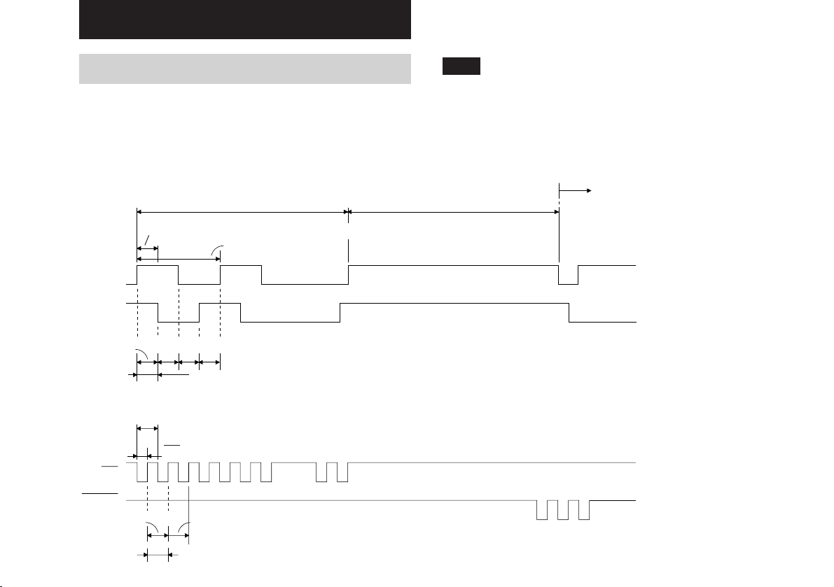
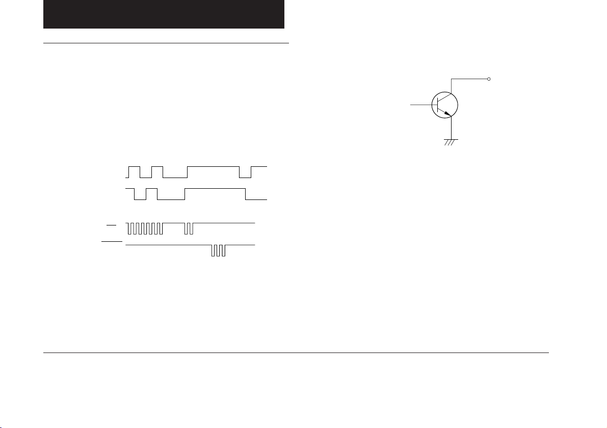
本デテクタは、出荷時〔分解能10μm、Tw20μs〕に設定
されています。
以下に、出荷時の出力信号仕様を表示します。
A/B信号出力仕様の場合
100μs
≅≅
Tw:最小位相差:20μs(PL21のみ20μs-0.9μs)
A
B
10μm
10μ10μ10μ
1分解能分
up/downパルス出力仕様の場合(PL21/PL22のみ)
Tw
Tw
2
UP
4Tw:最小周期:80μs
最小繰返し周期:20μs
パルス幅:(PL21)10μs+0.9μs,(PL22)10μs
注意 (PL21のみ)
最小位相差、パルス幅の0.9μsの補正値は、出力の負荷条
件(ケーブルの長さ、接続装置の受信回路など)により変
わります。
特に最小位相差、パルス幅が2.5μsをお使いの場合は出力
負荷を1kΩ以下となるようにしてください。
反転
100μs
A出力とB出力の位相差分を1カウントとし、これを分解能としま
す。
DOWN
10μm
10μm
1分解能分
出力パルスは、移動速度が遅い場合でも、Twごとに出力されるこ
とがあります。
3
Page 6
設定値を変更する場合
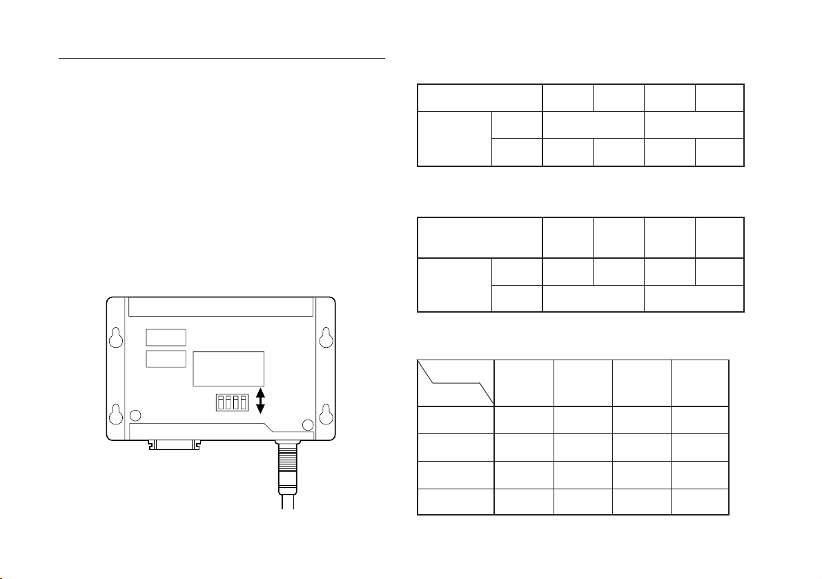
•分解能のスイッチ設定:表3-1.
分解能を変更したい場合や応答速度をあげたい場合は、以
下の手順で設定変更してください。
1. 筺体のカバーを取り外します。(M3×6ネジ2本)
2. 表3-1.、表3-2.を参考にして、プリント基板上のディッ
プスイッチ(図3-1.S101)を切り替えます。
3. 筺体のカバーを取り付け、ネジで固定します。
4. 以上の手順で機器に組付け、動作(カウント状態など)の
確認を行ってください。
S101
OFF
1234
ON
分解能(μm)
S101-1
スイッチ設定
S101-2
100
OFF
OFF
•応答速度のスイッチ設定:表3-2.
Tw(μs):
(出力サイクル数(Kpps))
S101-3
スイッチ設定
S101-4
2.5
(100)
OFF
OFF ON
•最大応答速度(m/min):表3-3.
Tw(μs)
分解能(μm)
100
50
20
2.5
300
300
300
5
300
300
192
50
ON
5
(50)
ON
10
300
240
96
20
OFF
10
(25)
OFF
10
ON
ON
20
(12.5)
ON
20
240
120
48
10
4
図3-1.
192
96
48
24
Page 7
3-2. ヘッドの取付け
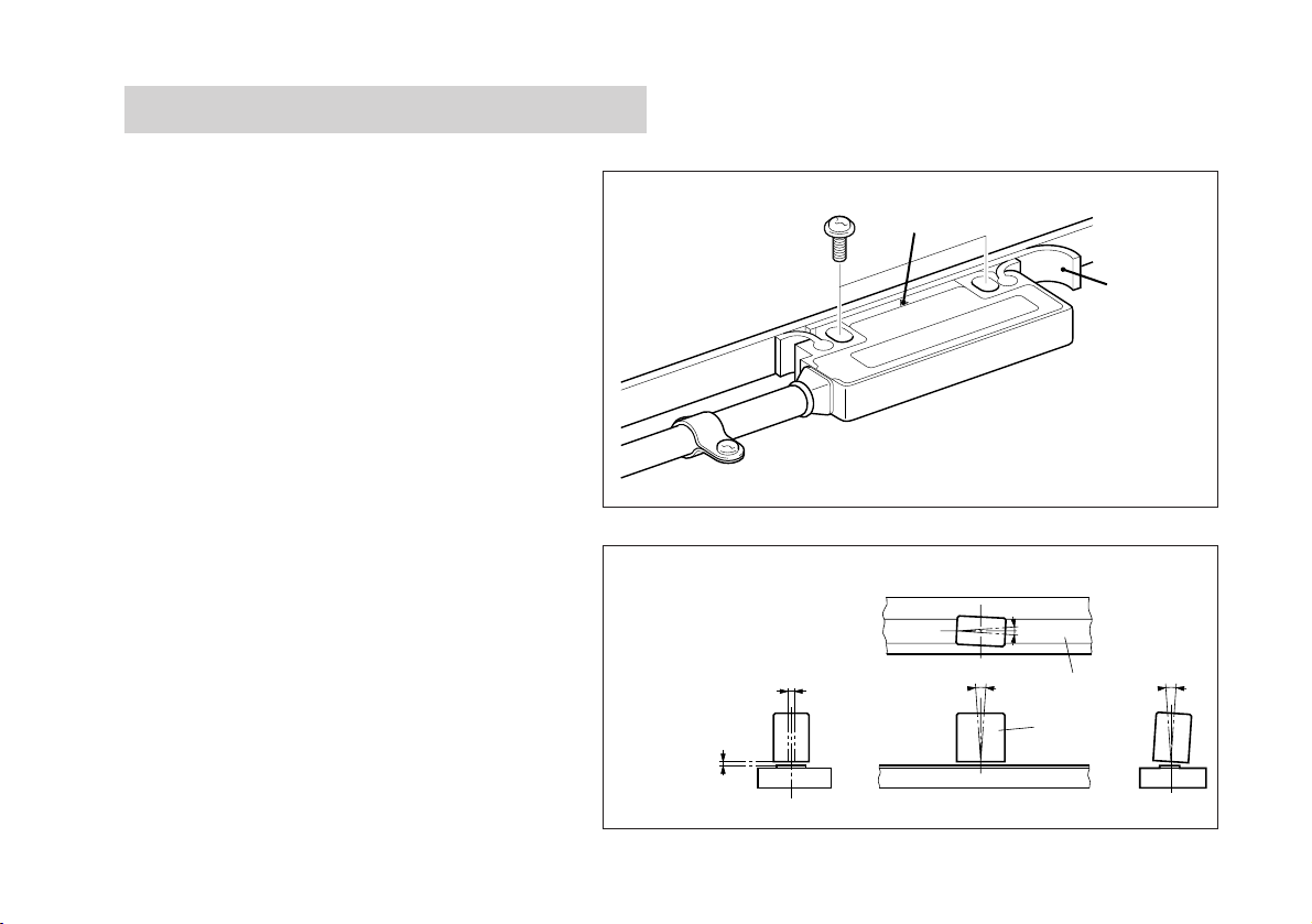
ヘッド部には、「▽」印が付いている位置に検出セ
ンサが内蔵されています。「▽」印がスケールの有
効長内に常にあるように設定してください。
• ヘッドの固定には、ヘッドの検出面とスケールと
の間にスペーサを挟み込み、付属のネジ(M4X2)
を用いて取り付けてください。
• ヘッド取付後、スペーサを抜きとってください。
• 締め付けトルクは、0.7N・m(7kg・cm)〜1.1N・m
(11kg・cm)としてください。
• ヘッド取付後、付属のケーブルクランプでケーブ
ルを固定し、引出し部のケーブルの遊びを押さえ
てください。
• スケールとヘッドの相対位置は、右図を参照して
ください。
1.5mm(最大)
クリアランス
±2mm
「▽」印
図3-2.
2
θ
<
±
0.5
1
θ
〇
スケール面
ヘッド
スペーサ
±
1
<
θ
3
3
θ
〇
<
〇
±
3
5
Page 8
3-3. 原点の取付けおよび動作確認(PL23のみ )
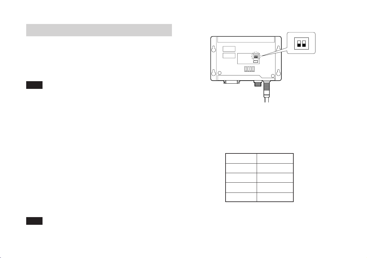
3-3-1. 取付け
別売のSET-P15-1の取扱説明書をご参照ください。
注意
スケール、ヘッド、原点を取付けた場合および取付け直し
た場合には、しっかりと固定してください。
S201
D201
S101
図3-3
AB F
ON
1
2
A
R
3-3-2. 動作確認
• 動作確認は、スケール、原点を取付けた場合および取付
け直した場合に行ってください。
• PL23本体のカバーを外して、原点通過時にLED(図3-3.
基板上D201)が点灯するかどうかで確認してください。
もしLEDが点灯しない場合には、基板上のスイッチ(図3-
3.S201のNo.2F/R)を切替えて、再度同一方向に原点通過
させ、LEDが点灯するか確かめてください。LEDが点灯
したら動作確認は終了となります。動作確認終了後は、
カバーを元通り取付けてください。
注意
原点を確実に取付けた後、動作確認を必ず行ってくださ
い。動作確認を怠ると原点がずれる可能性があります。
6
3-3-3. 応答速度
• 分解能によって異なります。
分解能
100μm
50μm
20μm
10μm
表3-4
応答速度
30m/min
15m/min
6m/min
3m/min
Page 9
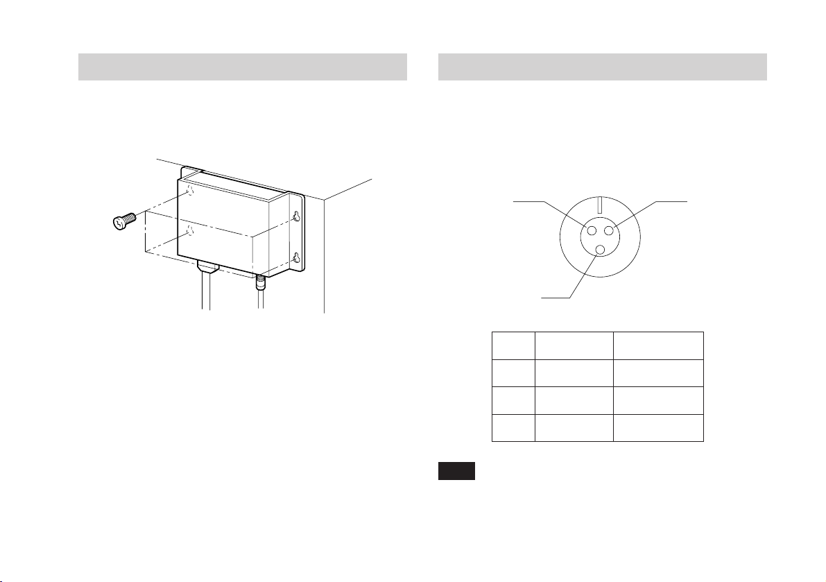
3-4.デテクタの取付け
3-5.原点入力コネクタ(PL23のみ)
デテクタの取り付けには、付属のネジ(+PSM4×10)で4ヶ所
とも固定してください。
図3-4
使用コネクタ(多治見無線製)
レセプタクル:R03-RB3F
プラグ:R03-PB3M(付属品)
A
No.
A
B
C
B
電源(+Vcc)
出力信号
電源(0V)
信号
ケ−ブル色相
C
赤
白
黒
注意
シールド線はプラグのケースに接続してください。
7
Page 10
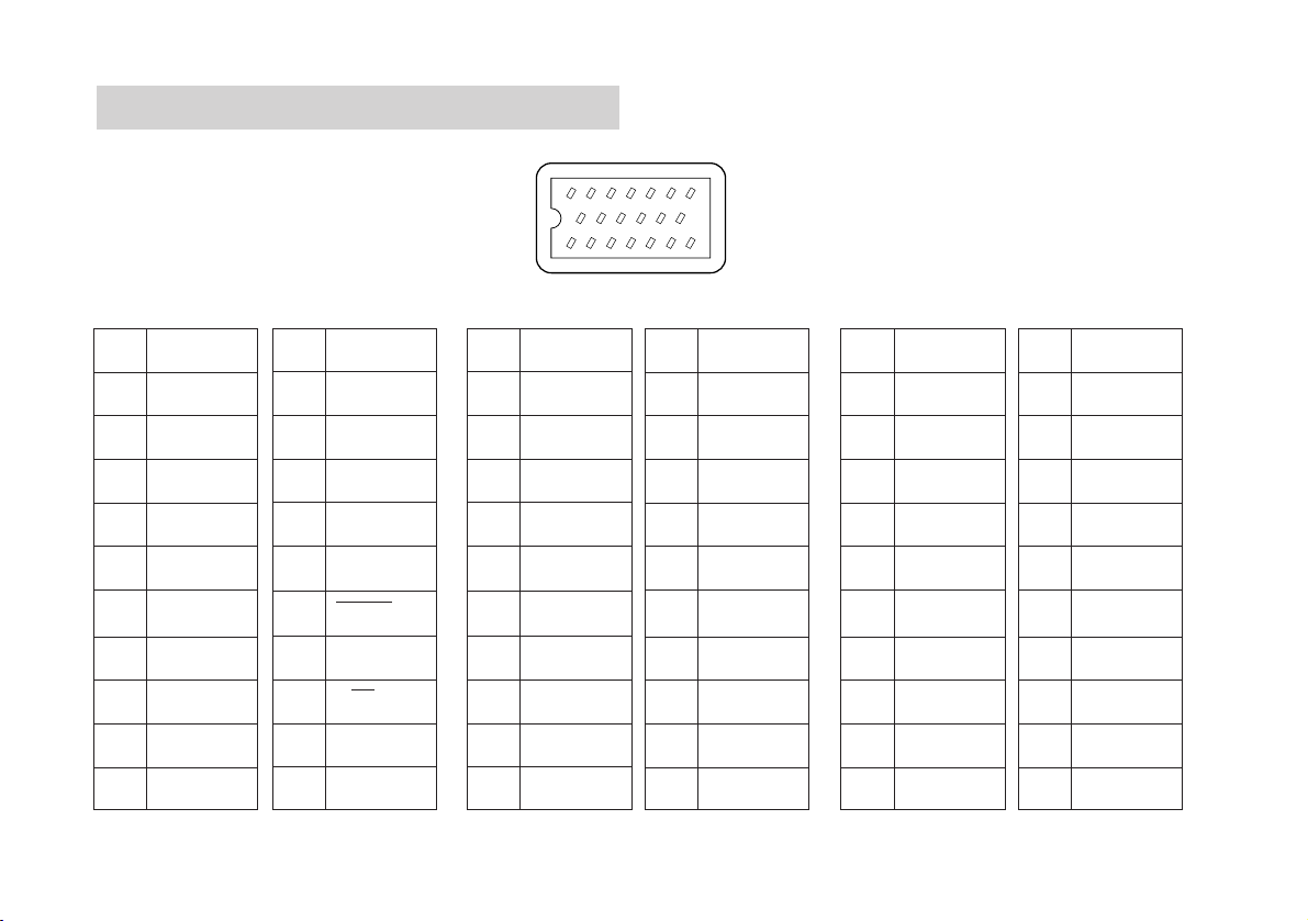
3-6. 出力コネクタ
使用コネクタ (本多通信工業製)
レセプタクル:MR-20RMAG
プラグ:MR-20LF(付属品)
PL21 PL22 PL23
No.
信号
No.
信号
No.
13 12 11 10 9 8
信号
No.
14151617181920
2134567
信号
No.
信号
No.
信号
1
2
3
4
5
6
7
8
9
10
×→接続禁止:接続禁止の端子には、ケーブルを接続しないでください。
8
0V
0V
0V
+12V
+12V
+12V
GND
×
×
×
11
12
13
14
15
16
17
18
19
20
×
ALARM
×
×
×
DOWN/PCA
×
UP/PCB
×
×
10
1
2
3
4
5
6
7
8
9
0V
0V
0V
+5V
+5V
+5V
GND
×
×
×
11
12
13
14
15
16
17
18
19
20
×
ALARM
*ALARM
×
×
*PCD/PCA
PCD/*PCA
*PCU/PCB
PCU/*PCB
RESET
10
1
2
3
4
5
6
7
8
9
0V
0V
0V
+5V
+5V
+5V
GND
×
×
×
11
12
13
14
15
16
17
18
19
20
×
ALARM
*ALARM
PCZ
*PCZ
PCA
*PCA
PCB
*PCB
RESET
Page 11
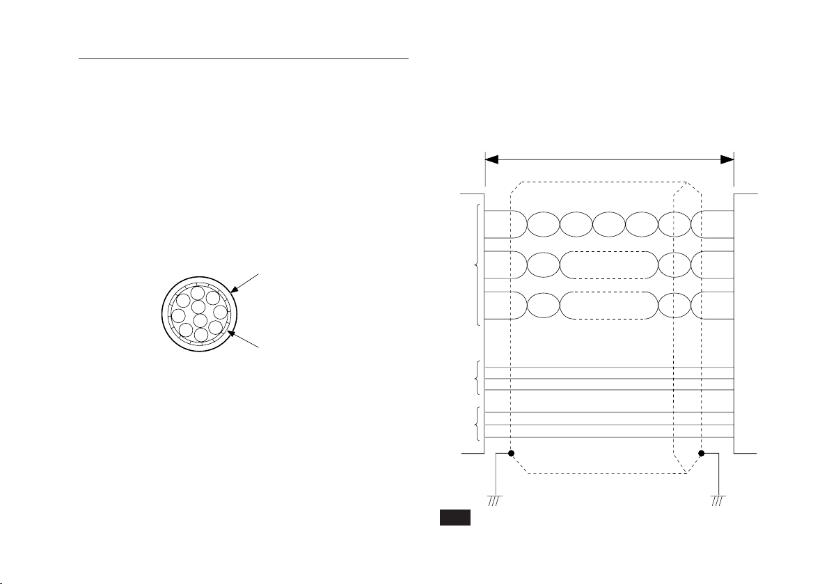
出力仕様図
出力ケーブルについて
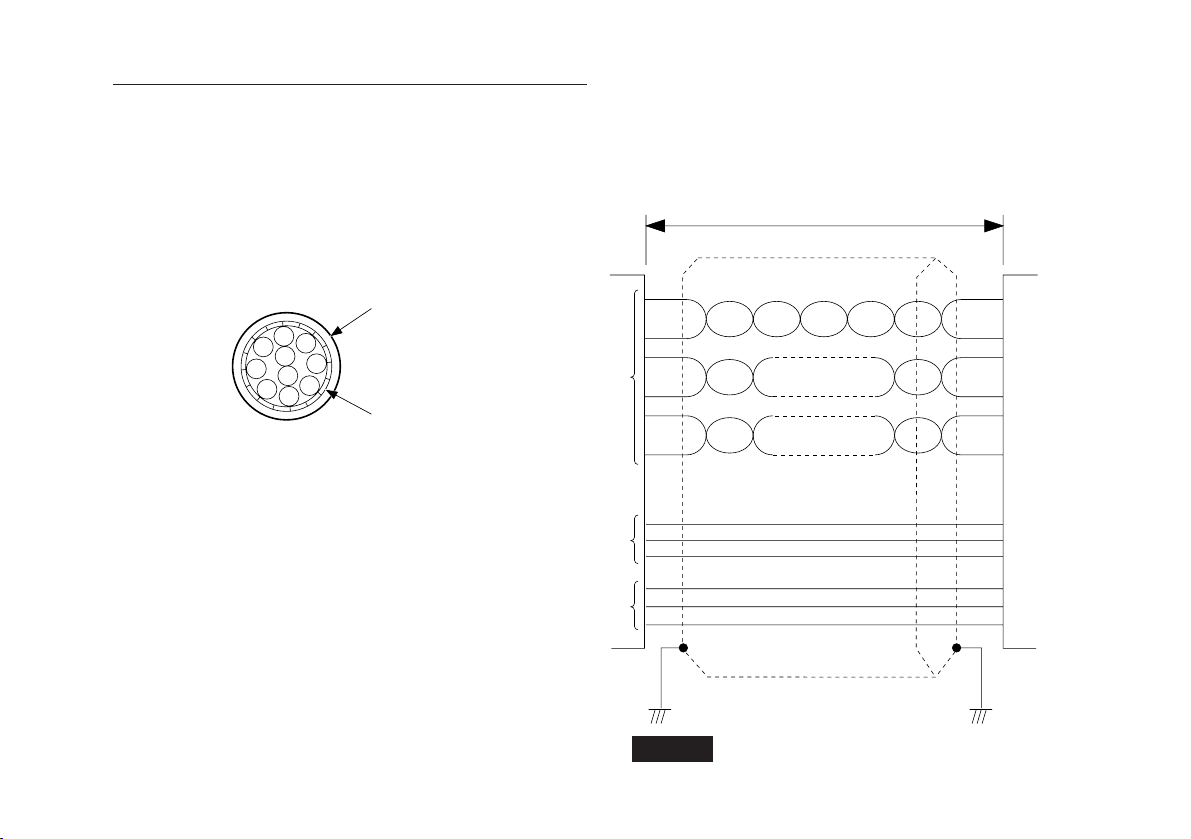
出力コネクタに接続するケーブルは、図のようなシールドさ
れたケーブルを使用してください。
デテクタ側のケーブルのシールド線は、デテクタ筺体に必ず
接続してください。
• 受信回路にはSN75115(相当品)を使用してください。
• 出力コネクタから電源を供給する場合はデテクタ入力部
で+5V±5%を満足するようにしてください。
50m以下
PL22/PL23
注意
接続機器
PL21/PL22/PL23
ケーブル断面
外皮
編組シールド
PL22
A/B相、アラーム
またはup/down、
アラーム
PL23
A/B相、原点アラーム
+5V
0V
注意
出力ケーブルはノイズ混入防止のため、短くしてください。
AWG28以上の太さの
ツイストペア線
9
Page 12
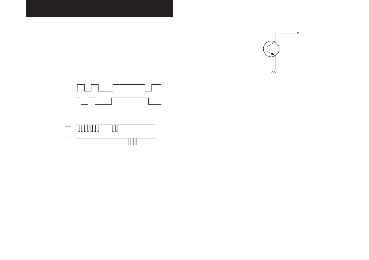
4.主な仕様
6.仕様
PL21の仕様
(OFF)
(OFF)
(ON)
(ON)
注意1
(OFF)
(OFF)
(3ページ参照)
(ON)
(OFF)
(OFF)
(ON)
(ON)
注意2
)
注意2
分解能 10μm/20μm/50μm/100μm
最小位相差(Tw)PL21-3F,AF:2.5μs/5μs/10μs/20μs(−0.9μs
最小繰返し周期(Tw)
PL21-3U,AUの2.5μs/5μs/10μs/20μs ( +0.9μs
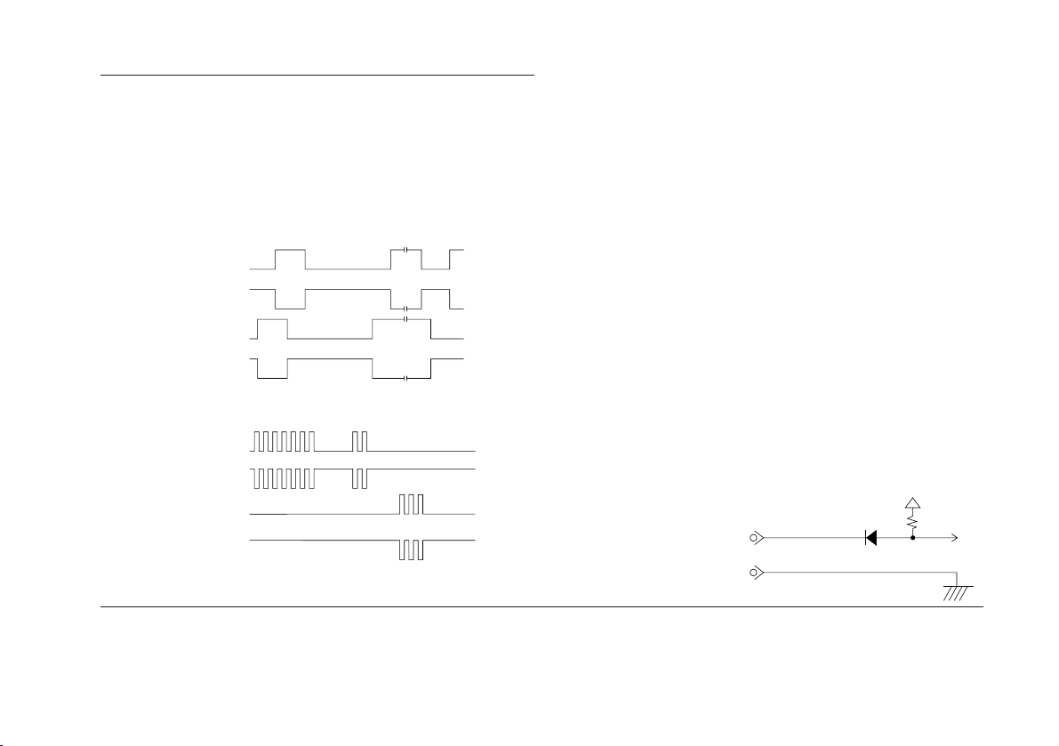
出力信号
注意3
PL21-3F,AF
A
B
(ON)
PL21-3U,AU
UP
UP
DOWN
DOWN
アラーム信号 スケールが最大応答速度を越えたとき、または
ヘッドケーブルなどの断線があったときに働きま
す。
正常時はアラーム出力はON状態であり、アラーム
が作動するとOFFとなります。電源を入れ直すこと
により、アラームが解除されます。
出力回路 オープンコレクタ
最大定格電圧:25V
最大定格電流:50mA
)
電源 DC+12V(±5%)
消費電力 0.8W(最大)
使用温度範囲 0〜+45℃
保存温度範囲 −10〜+50℃
ヘッドケーブル長
10m(PL21-AF,AU)、3m(PL21-3F,3U)
総重量 PL21-AF,AU:1030g
PL21-3F,3U:620g
付属品 ヘッド取付ネジ(M4×20).........................................2
デテクタ取付ネジ(M4×10) .....................................4
ケーブルクランプ用ネジ(M4×12).........................3
技術資料......................................................................1
出力コネクタ .........................................................1組
取扱説明書..................................................................1
ケーブルクランプ ..................................................... 3
スペーサ......................................................................1
A,B,ALARM
UP,DOWN
注意1
PL21-3U,AUのUp/Down出力は、必ずUp/Downカウンタで受信してくださ
い。片方のみの出力でご使用になりますと、正確な計測を行うことができま
せん。
注意2
10
この値は接続ケ−ブル長、接続回路で変わります。
注意3
移動量は、約100μsごとに検出され、この間に動いたスケール、またはヘッ
ドの変位量に相当するパルスとして出力されます。
A/B出力またはUp/Down出力信号は、一般のロータリーエンコーダと違い疑
似的に作っていますので、スケール移動速度が遅い場合でもあらかじめ設定
したパルス幅(Tw)で出力されることがあります。
受信回路は設定したパルス幅の信号を受けられるものが必要です。
Page 13
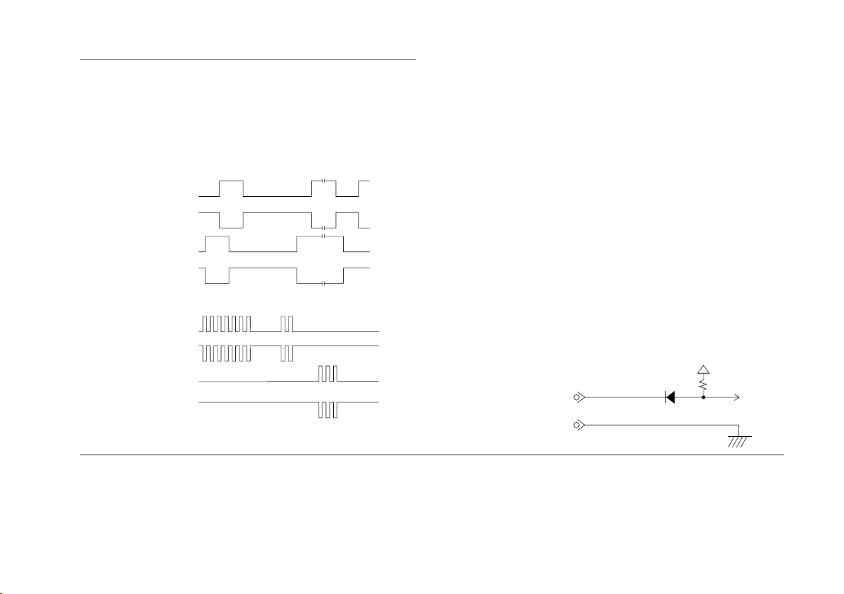
PL22の仕様
分解能 10μm/20μm/50μm/100μm
最小位相差(Tw) PL22-3F,AF:2.5μs/5μs/10μs/20μs
最小繰返し周期(Tw)
PL22-3U,AU:2.5μs/5μs/10μs/20μs
出力信号
注意2
PL22-3F,AF
PCA
*PCA
PCB
*PCB
PL22-3U,AU
PCU
*PCU
PCD
*PCD
注意1
(3ページ参照)
アラーム信号 スケールが最大応答速度を越えたとき、またはヘッ
ドケーブルなどの断線があったときに働きます。ア
ラーム発生時には、ALARM出力がHighになり、
*ALARM出力がLow になります。このとき、出力信
号は全てハイインピーダンスとなります。
アラーム解除 アラームの解除は、アラーム発生の原因を全て取り
除いた後にリセットをかけるか、または電源の再投
入をすることにより行われます。
また、アラーム状態であっても、外部リセットがか
かっていればアラーム信号は出力されず、ハイイン
ビーダンスにもなりません。ただし、出力信号は停
止します。
リセット リセットをかける場合には、出力コネクタの20番ピ
ンと7番ピンを短絡してください。
外部リセット信号入力仕様
最小リセット時間: 300ms
最大短絡電流: 0.5mA
最大動作復帰時間: 10msec
(リセット解除後)
外部リセット信号入力回路
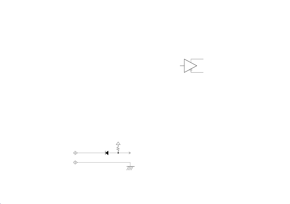
P20:RES
P7:GND
注意1
PL22-3U,AUのUp/Down出力は、必ずUp/Downカウンタで受信してくださ
い。片方のみの出力でご使用になりますと、正確な計測を行うことができま
せん。
注意2
移動量は、約100μsごとに検出され、この間に動いたスケール、またはヘッ
ドの変位量に相当するパルスとして出力されます。
A/B出力またはUp/Down出力信号は、一般のロータリエンコーダと違い疑似
的に作っていますので、スケール移動速度が遅い場合でもあらかじめ設定し
たパルス幅(Tw)で出力されることがあります。
受信回路は設定したパルス幅の信号を受けられるものが必要です。
11
Page 14

出力回路 各出力は電圧差動型ラインドライバ(SN75113)を使
用しています。したがって受信回路には電圧差動型
ラインレシーバ(SN75115相当品)をご使用くださ
い。
PCA,PCB,ALARMまたはPCU,PCD,ALARM
*PCA,*PCB,*ALARMまたは*PCU,*PCD,*ALARM
電源 DC+5V(±5%)
消費電力 2W(最大)
使用温度範囲 0〜+45℃
保存温度範囲 −10〜+50℃
ヘッドケーブル長
10m(PL22-AF,AU)、3m(PL22-3F,3U)
総重量 PL22-AF,AU:1030g
PL22-3F,3U:620g
付属品 ヘッド取付ネジ(M4×20) .........................................2
デテクタ取付ネジ(M4×10) .....................................4
ケーブルクランプ用ネジ(M4×8) ........................... 3
技術資料......................................................................1
出力コネクタ .........................................................1組
取扱説明書..................................................................1
ケーブルクランプ ..................................................... 3
スペーサ......................................................................1
12
Page 15
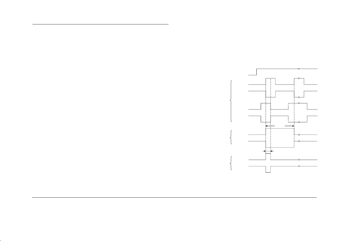
PL23の仕様
分解能 10μm/20μm/50μm/100μm(3ページ参照)
最小位相差(Tw) 2.5μs/5μs/10μs/20μs
接続可能な原点検出器
SET-P15-1(別売)
出力信号および原点出力信号
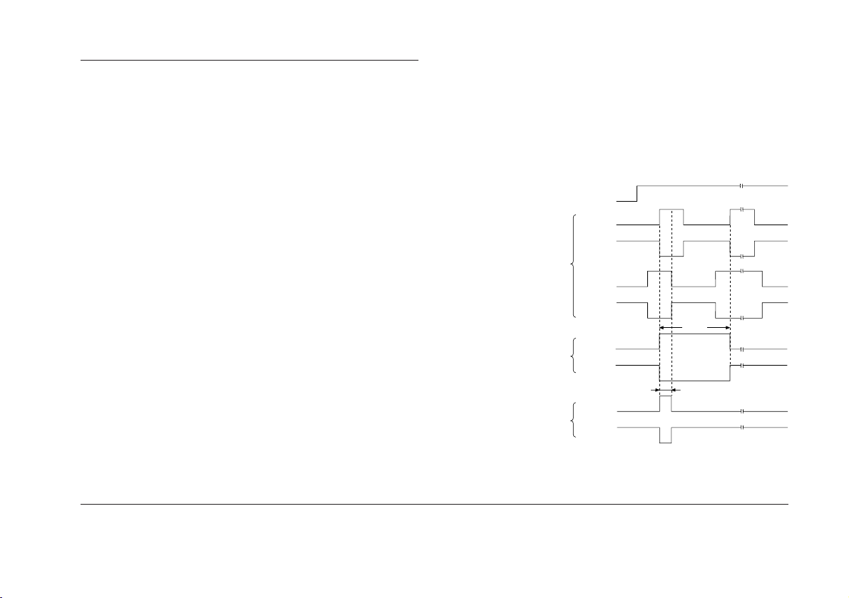
原点信号は出力パルスと同期しており、基板上の
スイッチ(図3-3.S201No.1A/AB)の切替えにより、
図の信号が出力されます。
原点出力信号は、スケールの動作に対して両方向
で出力されますが、片方向のみ参照し、原点通過
時にLEDが点灯する状態で使用してください。
注意
原点入力信号
PCA
*PCA
出力パルス
PCB
*PCB
注意
移動量は、約100μsごとに検出され、この間に動いたスケール、またはヘッ
ドの変位量に相当するパルスとして出力されます。
A/B出力またはUp/Down出力信号は、一般のロータリエンコーダと違い疑似
原点出力パルス
S201
No.1SW=A側のとき
(4パルス幅出力)
PCZ
*PCZ
4Tw
Tw
S201
No.1SW=AB側のとき
(1パルス幅出力)
的に作っていますので、スケール移動速度が遅い場合でもあらかじめ設定し
たパルス幅(Tw)で出力されることがあります。
受信回路は設定したパルス幅の信号を受けられるものが必要です。
PCZ
*PCZ
13
Page 16
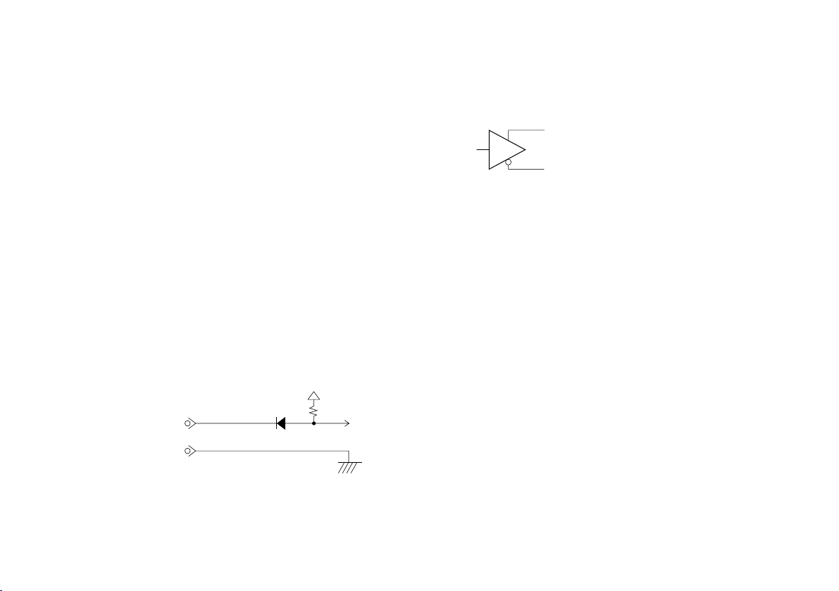
アラーム信号 スケールが最大応答速度を越えたとき、またはヘッ
ドケーブルなどの断線があったときに働きます。ア
ラーム発生時には、ALAR M 出力がH i g h になり、
*ALARM出力がLow になります。このとき、原点信
号を除く出力信号はすべてハイインピーダンスとな
ります。
アラーム解除 アラームの解除は、アラーム発生の原因を全て取り
除いた後にリセットをかけるか、または電源の再投
入をすることにより行われます。
また、アラーム状態であっても、外部リセットがか
かっていればアラーム信号は出力されず、ハイイン
ピーダンスにもなりません。ただし、出力信号は停
止します。
リセット リセットをかける場合には、出力コネクタの20番ピ
ンと7番ピンを短絡してください。
外部リセット信号入力仕様
最小リセット時間: 300ms
最大短絡電流: 0.5mA
最大動作復帰時間: 10msec
(リセット解除後)
外部リセット信号入力回路
P20:RES
P7:GND
出力回路 各出力は電圧差動型ラインドライバ(SN75113)を使
用しています。したがって受信回路には電圧差動型
ラインレシーバ(SN75115相当品)をご使用くださ
い。
PCA,PCB,PCZ,ALARM
*PCA,*PCB,*PCZ,*ALARM
原点精度 1パルス幅/4パルス幅(切替え)
例: 10μm分解能に設定した場合、精度は10μm
(1パルス幅)または40μm(4パルス幅)。
電源 DC+5V(±5%)
消費電力 2W(最大)
使用温度範囲 0〜+45℃
保存温度範囲 −10〜+50℃
ヘッドケーブル長
10m(PL23-AF)、3m(PL23-3F)
総重量 PL23-AF:1030g
PL23-3F:620g
付属品 ヘッド取付ネジ(M4×20).........................................2
デテクタ取付ネジ(M4×10) .....................................4
ケーブルクランプ用ネジ(M4×8) ........................... 3
技術資料......................................................................1
出力コネクタ .........................................................1組
取扱説明書..................................................................1
ケーブルクランプ ..................................................... 3
スペーサ......................................................................1
14
Page 17
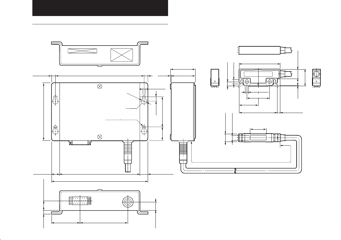
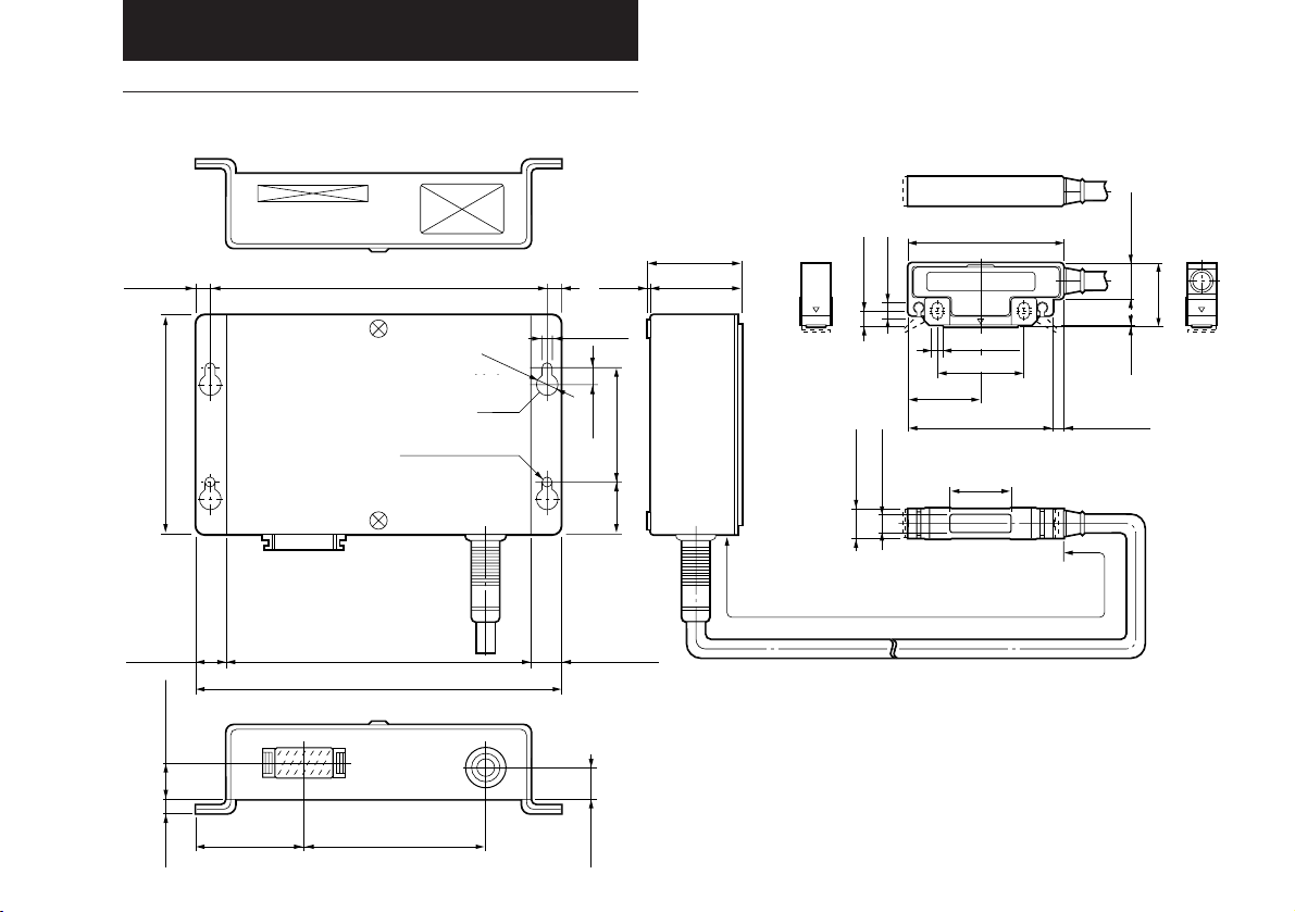
5.外形寸法図
PL21/PL22
92/3.62"
12/0.47"
5/0.19" 1.6/0.63"
138/5.43"6/0.24"
Bohrung 2-Ø4.6
126/4.96"
150/5.91"
75/2.95"45/1.77"
2-Ø4.6 hole
2-φ4.6穴
Ø8
Hole
穴
Loch
(6)/(0.24")
4.6/0.18"
(12)/(0.47")
(1.9)
(0.07")
6.5
0.26"
21
13/0.51"
(38.9)/(1.53")
37/1.46"
50/1.97"
0.83"
63/2.48"
7/0.28"
6/0.24"
4.5/0.18"
35/1.38"
29.5
1.16"
59/2.32"
28.6/1.13"
7.6/0.3"
12/0.47"
Cable length:3/9.8',10/32.8'(m/feet)
ケーブル長 3m,10m
Kabellänge:3(m),10(m)
15/0.59"
26.5
1.04"
1
0.04"
(4)/(0.16")
単位:mm/インチ
15
Page 18
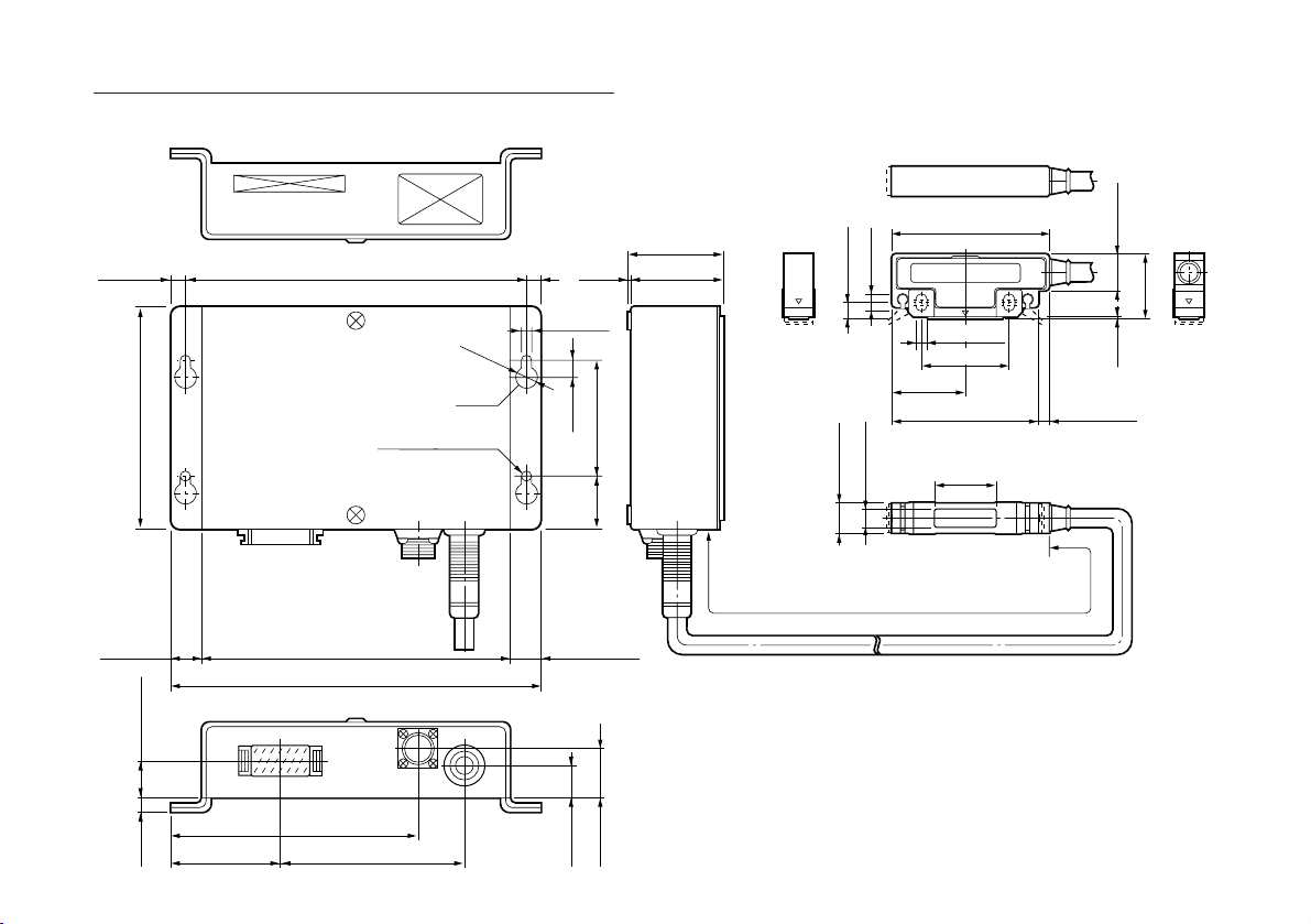
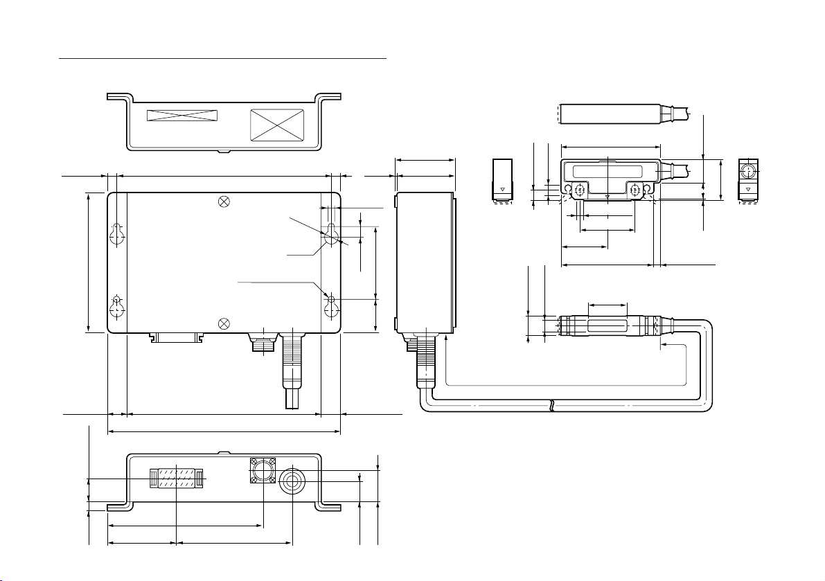
PL23
16
92/3.62"
12/0.47"
5/0.19" 1.6/0.63"
45/1.77"
138/5.43"6/0.24"
126/4.96"
150/5.91"
102/4.02"
75/2.95"
Ø8/Ø0.29"
Hole
穴
Loch
2-Ø0.18"hole
2-φ4.6穴
Bohrung 2-Ø4.6
(6)/(0.24")
4.6/0.18"
(12)/(0.47")
(1.9)
(0.07")
6.5
0.26"
21
13/0.51"
20/0.79"
(38.9)/(1.53")
37/1.46"
50/1.97"
0.83"
63/2.48"
7/0.28"
6/0.24"
4.5/0.18"
35/1.38"
29.5
1.16"
59/2.32"
28.6/1.13"
7.6/0.3"
12/0.47"
Cable length:3/9.8',10/32.8'(m/feet)
Kabellänge:3(m),10(m)
ケーブル長 3m,10m
15/0.59"
26.5
1.04"
1
0.04"
(4)/(0.16")
単位:mm/インチ
Page 19

CONTENTS 1. NOTES TO USERS
1. NOTES TO USERS ................................................... 17
1-1. General Precautions .......................................... 18
1-2. Notes of setting .................................................. 18
1-3. Installation ......................................................... 18
2. INTRODUCTION ....................................................... 18
3. OPERATION ............................................................. 19
3-1. Setting Resolution and Output Pulse Width ...... 19
3-2. Head Installation ................................................ 21
3-3. Installation of Reference Point and Operation Check .. 2 2
3-4. Detector Installation ........................................... 23
3-5. Reference Point Signal Input Connector(PL23) 23
3-6. Output Connector .............................................. 24
4. SPECIFICATIONS .................................................... 26
PL21 .......................................................................... 26
PL22 .......................................................................... 27
PL23 .......................................................................... 29
5. DIMENSIONS ............................................................ 31
PL21/PL22................................................................. 31
PL23 .......................................................................... 32
Read all instructions carefully before starting use.
Save this MANUAL for future reference.
Warning —This equipment has been tested and found to comply
with the limits for a Class A digital device, pursuant to Part 15 of the
FCC Rules. These limits are designed to provide reasonable
protection against harmful interference when the equipment is
operated in a commercial environment. This equipment generates,
uses, and can radiate radio frequency energy and, if not installed and
used in accordance with the instruction manual, may cause harmful
interference to radio communications. Operation of this equipment in a
residential area is likely to cause harmful interference in which case the
user will be required to correct the interference at his own expense.
You are cautioned that any changes or modifications not expressly
approved in this manual could void your authority to operate this
equipment.
1-1. General Precautions
When using Sony Manufacturing Systems Corporation products,
observe the following general precautions along with those given
specifically in this manual to ensure proper use of the products.
• Before and during operations, be sure to check that our
products function properly.
• Provide adequate safety measures to prevent damages in
case our products should develop malfunction.
• Use outside indicated specifications or purposes and
modification of our products will void any warranty of the
functions and performance as specified of our products.
• When using our products in combination with other equipment,
the functions and performances as noted in this manual may
not be attained, depending upon operating environmental
conditions. Make full study of the compatibility in advance.
17
Page 20

2. INTRODUCTION
1-2. Notes of setting
When installing the Digiruler units, observe the following to
prevent noise interference from other equipment.
1. Apply preventive measures to relays, solenoids and
motors connected to the Digiruler units against noise
interference.
2. Take preventive steps when the noises from other
equipment may disturb the power supply line to the
Digiruler units.
3. Shield the quadrature square wave signal (A/B phase)
output cable correctly according to the instruction
manual.
Be sure to ground the Digiruler units by connecting it to
the machine using an earth wire or by monuting it on the
machine with screws.
1-3. Installation
• Use the PL21/PL22/PL23 in the temperature range of 0
to 45°C/32 to 113°F. Do not expose it to the sunlight or
source of heat. A well-ventilated place is preferable.
• Install the PL21/PL22/PL23 at least 0.5 m away from noise
sources such as large-power relays, high-voltage sources
and large-current switches.
• Separately route the head cable and output cable from the
18
power line.
The PL21/PL22/PL23 is a Digiruler position detection unit
made up of a scale signal detection head and a detector
connected by cable. Just by turning on the power the position
and displacement can be obtained via pulse signals. By
connecting the PL21/PL22/PL23 with the optional SL100
series scale unit a position/displacement detection system
can be set up easily.
The PL21/PL22/PL23 can be used with former Digiruler scale
models but then accuracy of the system will be that of the
former scale.
FEATURES
• The detection head and scale are non-contacting, offering
excellent resistance against vibration and shock.
• The PL21/PL22/PL23 is little affected by external
magnetism and its high precision is protected against
changes in head clearance.
• The detection head and detector are directly connected by
a cable, and it merely needs to be installed on the machine
and supplied power to output displacement in pulse
signals. Thus, it is simple to operate.
• The PL21 operates on 12 V DC power supply.
• The PL22/PL23 operate on 5 V DC power supply.
• The minimum resolution is 10 µm.
• Reference point signal in synch with A/AB-phase signal
can be output.(PL23 only)
Page 21
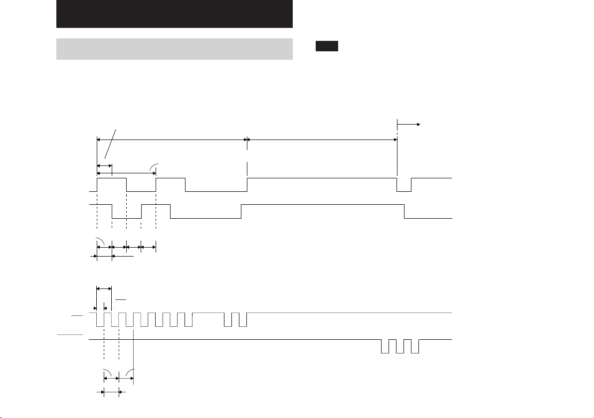
3. OPERATION
3-1.
Setting Resolution and Output Pulse Width
The resolution of this detector is factory-set to 10 µm, TW 20 µs.
Shown below are the output signal specifications for factory setting.
A/B signal output specifications
Tw: Minimum phase difference: 20 µs (20 µs – 0.9 µs at PL21)
100μs
≅≅
4Tw: Minimum period: 80 µsec
A
B
10μm
10μ10μ10μ
Resolution
(ON)
Up/Down pulse output specifications (PL21/PL22)
Tw
Tw
2
UP
Note (PL21)
The compensation value of 0.9 µsec for the minimum phase
difference and pulse width will differ according to output load
conditions (cable length, receiving circuit of connected
device, etc.). When setting the minimum phase difference
and pulse width to 2.5 µs, adjust the output load 1 kΩ or less.
Reverse
100μs
(OFF)
(OFF)
(ON)
The phase difference between A output and B output is
designated as 1 count and also resolution.
DOWN
10μm
10μm
Resolution
Minimum repeat cycle: 20 µs
Pulse width: (PL21) 10 µs + 0.9 µs
(PL22) 10 µs
Output pulse is sometimes output for every Tw even when the
movement speed is slow.
19
Page 22
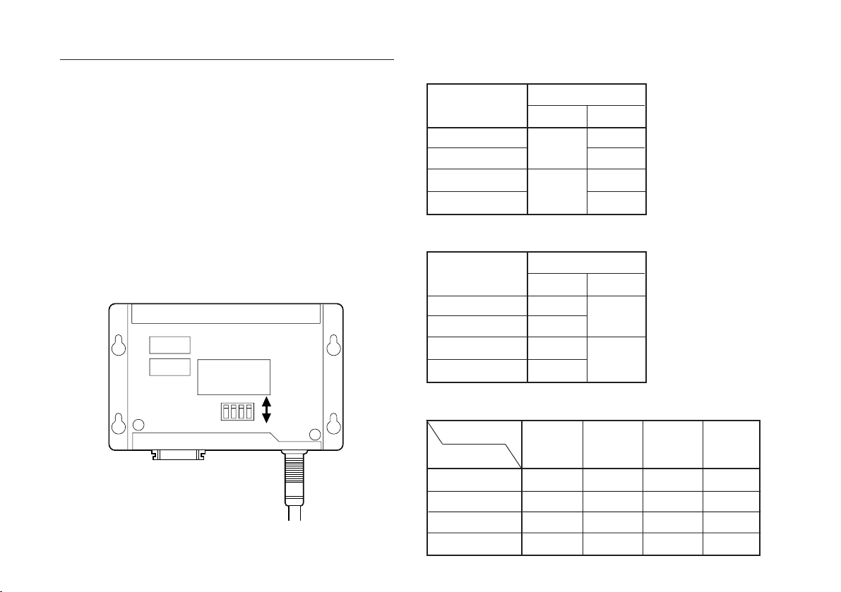
Change the Resolution
To change the resolution or increase the response speed,
follow the procedure below.
1. Remove the cover (two M3 × 6 screws).
2. Reset the dip switches on the printed circuit board (Fig.
3-1. S101) by referring to Tables 3-1 and 3-2.
3. Reinstall the cover and fasten with screws.
4. Install the unit on the machinery and confirm
operations (counter status, etc.)
• Resolution switch setting: (Table 3-1.)
Resolution (µm)
100
50
20
10
Switch setting
S101-1
OFF
ON
S101-2
OFF
ON
OFF
ON
• Responce speed switch setting: (Table 3-2.)
20
S101
Fig. 3-1
TW (µsec)
Output cycle (kpps)
2.5 (100)
5 (50)
10 (25)
20 (12.5)
OFF
1234
ON
• Maximum response speed (m/min):(Table 3-3.)
Tw (µs)
Resolution (µm)
100
50
20
10
Switch setting
S101-3
OFF
ON
OFF
ON
2.5
300
300
300
192
S101-4
OFF
ON
5
300
300
192
96
10
300
240
96
48
20
240
120
48
24
Page 23
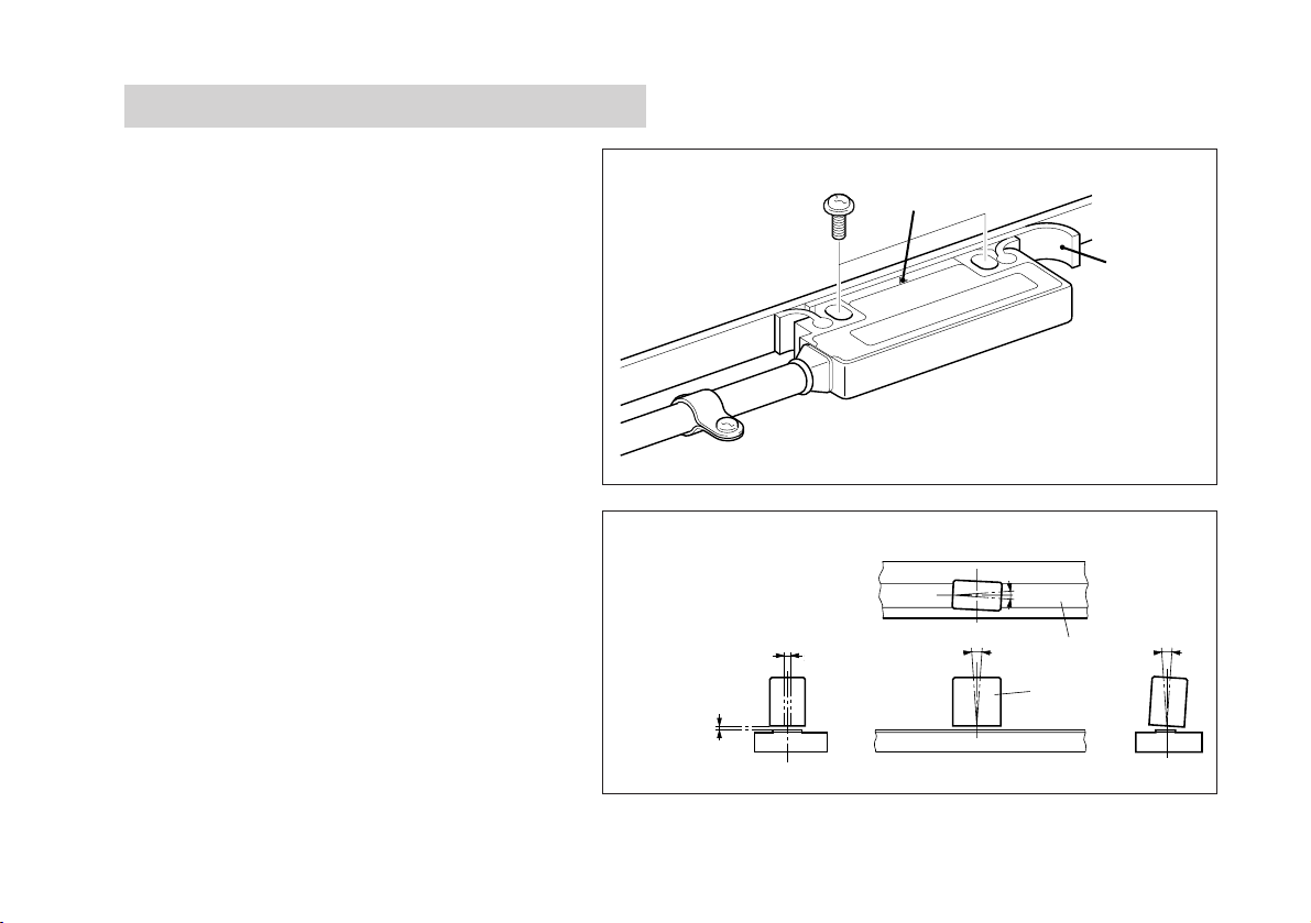
3-2. Head Installation
The detection sensor is built into head where it is
marked with “∇”. Install the head so that the “∇”
mark is always within the measuring length of the
scale.
• To fasten the head, insert the accessory spacer
between the detection surface of the head and the
scale, and install with the accessory screws (M4 × 20).
• After installing the head, remove the spacer.
• Tightening torque should be 0.7 N·m (7 kg·cm) to
1.1 N·m (11 kg·cm).
• After installing the head, use the accessory cable
clamps to fasten the cable where it extends from
the head. Make sure the cable is not loose.
• The relative positions of the scale and head should
be as shown in Fig. 3-2.
Clearance
1.5 mm/0.06"
(Max.)
±2 mm/±0.08"
±2mm
“∇” mark
θ
2
<
1
θ
〇
±
0.5
Scale surface
Head
Spacer
1
<
θ
±
3
θ
〇
3
<
〇
±
3
Fig. 3-2
21
Page 24
3-3. Installation of Reference Point and
Operation Check (PL23)
3-3-1. Installation
Refer to the instruction manual of the optional SET-P15-1.
Note
When the scale, head and reference point have been
installed, or when they have been re-installed, fasten them
tightly.
3-3-2. Operation Check
• Check the operation after installing, or reinstalling, the
scale and reference point.
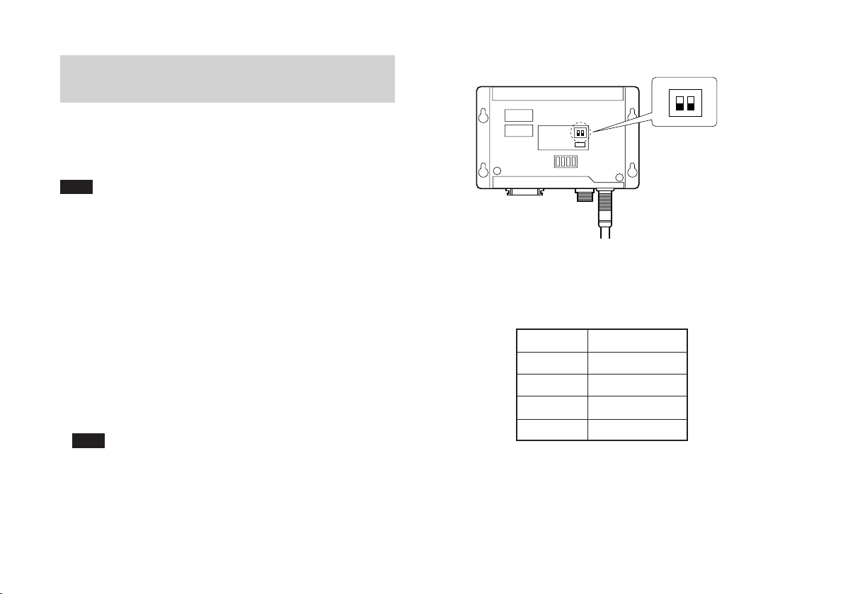
• Remove the cover of the PL23 unit and check the LED (Fig.
3-3. D201) lights when the reference point is passed. If the
LED does not light, move the switch on the board (Fig. 3-3.
S201 No.2, F/R) from the position F to R (or R to F), and
pass the reference point once again in the same direction
and confirm that the LED lights. Then reinstall the cover.
Note
Install the reference point securely and properly carry out
the operation check to prevent the reference point from
slipping.
AB F
ON
1
2
A
S201
D201
S101
Fig. 3-3
3-3-3. Responce Speed
• The responce speed varies with the resolution.
Resolution
100 µm
50 µm
20 µm
10 µm
Responce Speed
30 m / min
15 m / min
6 m / min
3 m / min
Table 3-4
R
22
Page 25
3-4. Detector Installation
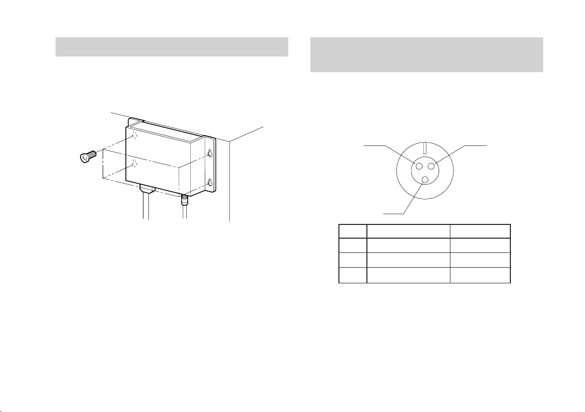
To install the detector, use four accessory screws (+PS M4 ×
10) to fasten the detector.
3-5. Reference Point Signal Input Connector
(PL23)
Connector used: (Tajimi Musen)
R03-RB3F Receptacle
R03-PB3M Plug (Provided)
Fig. 3-4
A
B
No.
A
Power Supply (+Vcc)
B
Output Signal
C
Power Supply (0 V)
Signal
Cable Color
C
Red
White
Black
Note: Connect the shielding to the shell of the connector.
23
Page 26
3-6. Output Connector
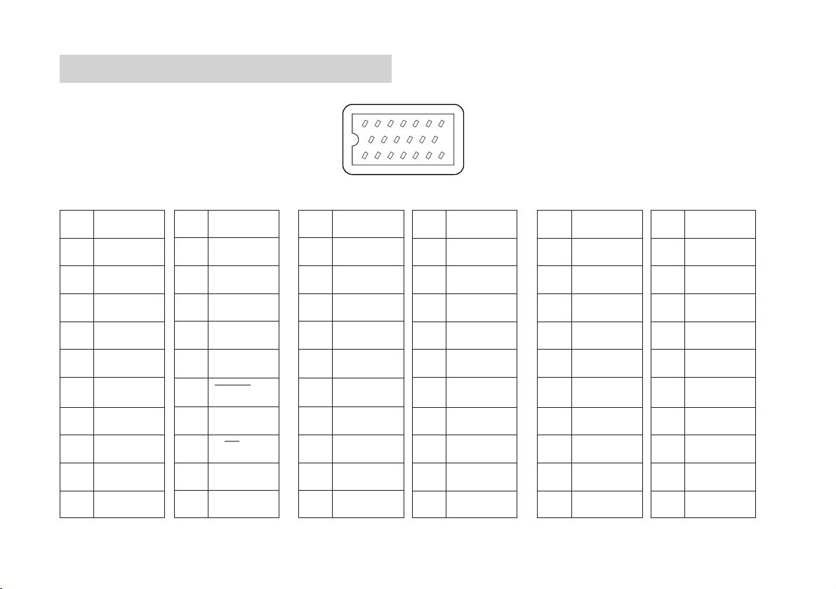
Connector used: (Honda Tsushin)
MR-20 RMAG Receptacle
MR-20LF Plug (Provided)
PL21 PL22 PL23
No.
Signal
No.
Signal
No.
13 12 11 10 9 8
Signal
2134567
No.
14151617181920
Signal
No.
Signal
No.
Signal
1
2
3
4
5
6
7
8
9
10
× → Connection inhibit: Never wire the connection inhibit pin.
24
0V
0V
0V
+12V
+12V
+12V
GND
×
×
×
11
12
13
14
15
16
17
18
19
20
×
ALARM
×
×
×
DOWN/PCA
×
UP/PCB
×
×
10
1
2
3
4
5
6
7
8
9
0V
0V
0V
+5V
+5V
+5V
GND
×
×
×
11
12
13
14
15
16
17
18
19
20
×
ALARM
*ALARM
×
×
*PCD/PCA
PCD/*PCA
*PCU/PCB
PCU/*PCB
RESET
10
1
2
3
4
5
6
7
8
9
0V
0V
0V
+5V
+5V
+5V
GND
×
×
×
11
12
13
14
15
16
17
18
19
20
×
ALARM
*ALARM
PCZ
*PCZ
PCA
*PCA
PCB
*PCB
RESET
Page 27
Output Specifications
Output cable
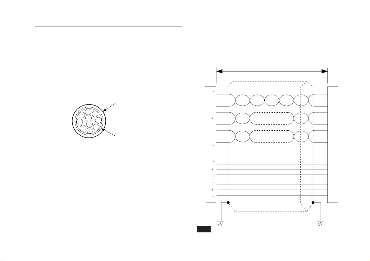
Use a shielded cable like the one shown in the illustration to
connect to the output connector. The other end of the
shielded cable must be connected to the detector body.
PL21/PL22/PL23
• Use SN75115 (or equivalent)as receiving circuit.
• When the power is supplied through the output connector,
make sure that the voltage at the PL22/PL23 input terminal
is +5 V ±5%.
50 m/164' min or less. (See note below)
PL22/PL23
Connected
equipment
Cross section of the cable
Outer coating
Shield
PL22
A/B phase, Alarm or
up/down, Alarm
PL23
A/B phase,
Reference point alarm
Twisted pair (28 AWG or thicker)
+5V
0V
Note
Shorten the output cable to improve noise immunity.
25
Page 28
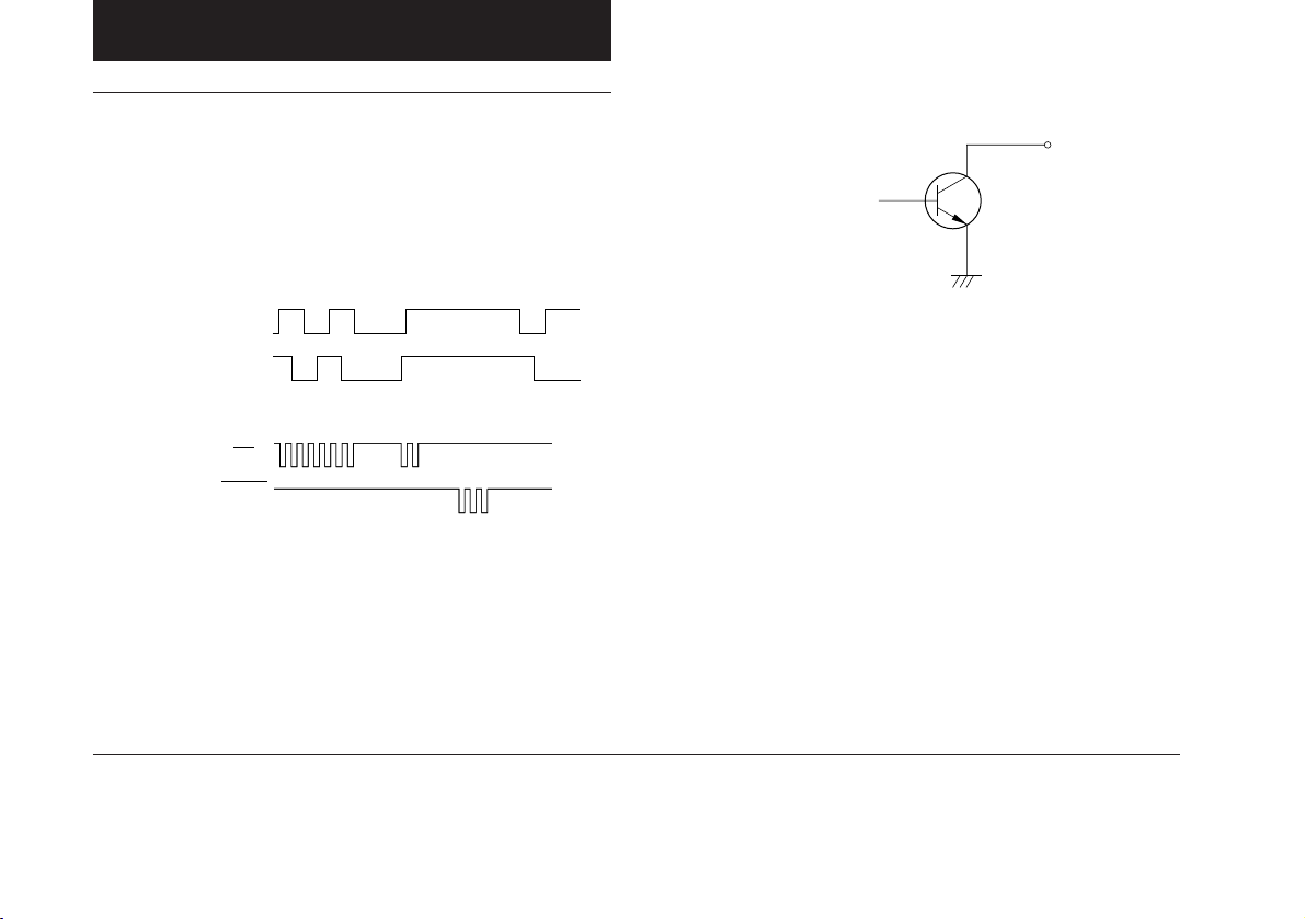
4. SPECIFICATION
PL21
(ON)
(ON)
Note 1
(OFF)
(OFF)
(OFF)
(OFF)
(See P.19)
(ON)
(OFF)
(OFF)
(ON)
(ON)
Note 2
Note 2
Resolution 10 µm/20 µm/50 µm/100 µm
Minimum phase difference (Tw)
PL21-3F, AF: 2.5 µs/5 µs/10 µs/20 µs (−0.9 µs
Minimum repeat cycle (Tw)
PL21-3U, AU: 2.5 µs/5 µs/10 µs/20 µs (+0.9 µs
Output signal
Note 3
PL21-3F, AF
A
B
(ON)
PL21-3U, AU
UP
UP
DOWN
DOWN
Alarm signal If the scale exceeds the maximum responce speed
or if a head cable connection becomes open, an
alarm is triggered.
The alarm output is ON during normal operation and
it is turned OFF when the alarm is triggerd. The
alarm can be reset by turning the power back on.
Output circuit
Open collector
Maximum rated voltage: 25 V
Maximum rated current: 50 mA
)
)
Power requirements
DC +12 V (±5%)
Power consumption
0.8 W (Max.)
Operating temperature range
0 to +45 °C/32 to 113 °F
Storage temperature range
−10 to +50 °C/14 to 122 °F
Head cable length
10 m (PL21-AF, AU), 3 m (PL21-3F, 3U)
Total weight PL21-AF, AU: 1030 g / 2.318 sb
PL21-3F, 3U: 620 g / 1.395 sb
Accessories Head installation screws (M4×20) ............... 2 pcs.
Detector installation screws (M4×10) .......... 4 pcs.
Cable clamp screws (M4×12) ...................... 3 pcs.
Techinical Information ................................... 1 pc.
Output connector ........................................... 1 set
Instruction manual ......................................... 1 pc.
Cable clamps ............................................... 3 pcs.
Spacer ............................................................ 1 pc.
A, B, ALARM
UP, DOWN
Note 1
The PL21-3U, AU is always receive Up/Down output with the Up/Down counter. Accurate
measurement cannot be obtained if only one output is used.
Note 2
26
This value differs depending on connection cable length and connected circuits.
Note 3
The displacement is detected about every 100 µs to generate pulses corresponding to the
displacement of the scale or head.
As the A/B output or Up/Down output signal, unlike common rotary encoder, is artificially
generated, it is sometimes output at the present pulse width (Tw) even when the scale
movement is slow. It is necessary to use a receiving circuit that can receive the present
pulse width.
Page 29
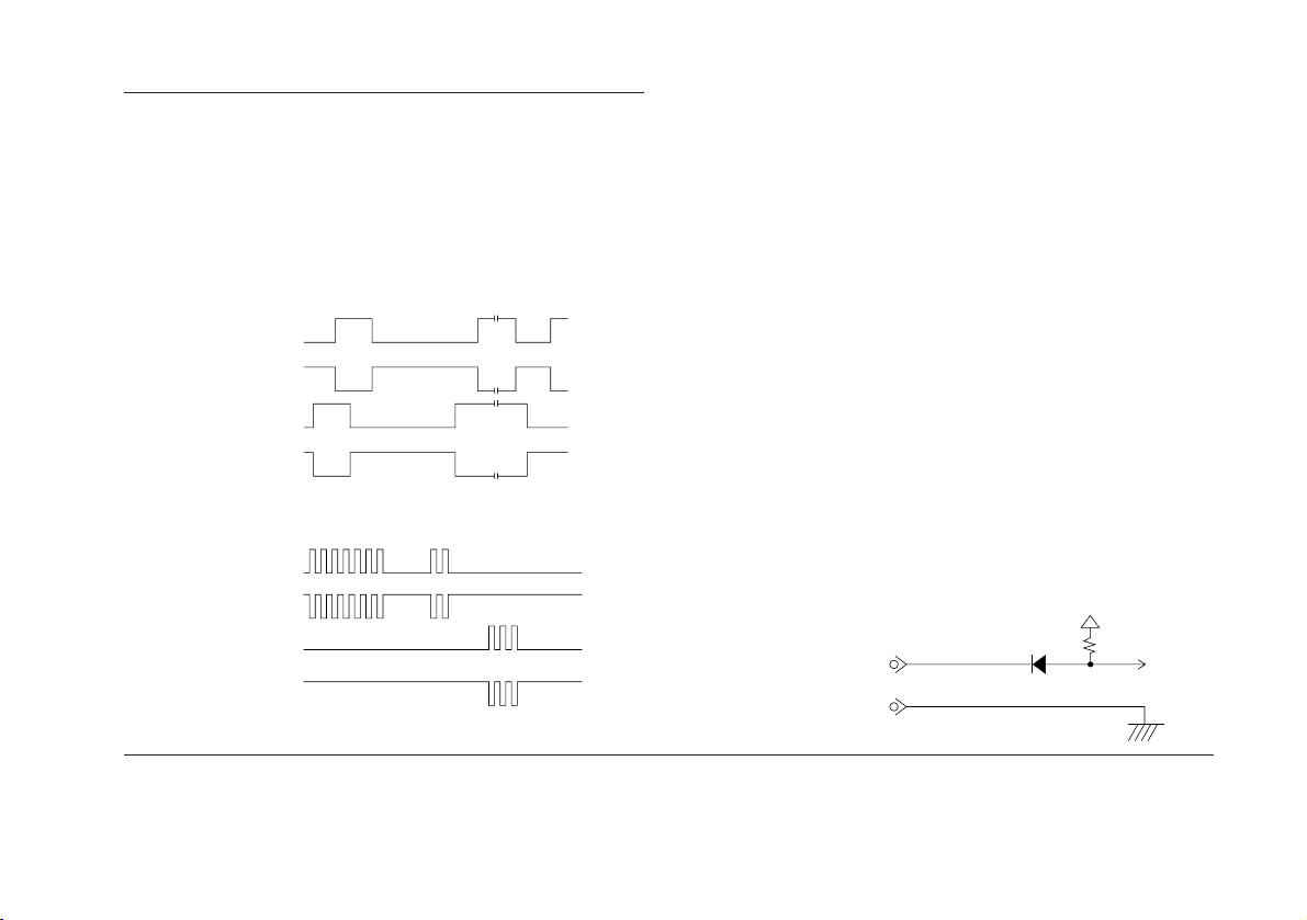
PL22
Resolution 10 µm/20 µm/50 µm/100 µm
Minimum phase difference (Tw)
Minimum repeat cycle (Tw)
Output signal
PL22-3F, AF: 2.5 µsec/5 µsec/10 µsec/20 µsec
PL22-3U, AU: 2.5 µsec/5 µsec/10 µsec/20 µsec
Note 2
PL22-3F, AF
PCA
*PCA
PCB
*PCB
PL22-3U, AU
PCU
Note 1
(See P.19)
Alarm signal If the scale exceeds the maximum response speed
or if a head cable connection becomes open, an
alarm is triggered. When an alarm is triggered, the
ALARM output goes high (the *ALARM output goes
LOW). At this time, the output signal becomes
entrirely high impedance.
Alarm clearing
To reset the alarm, remove all the causes of the
alarm and perform a reset or remove power and
apply power once again.
With the alarm triggered, if the external reset is
begin applied, the alarm signal will not be output
and outputs will not go into the high-impedance
state. However, the output signals will be stopped.
Reset To perform a reset, short pins 20 and 7 of the
output connector.
External reset signal input
Maximum reset time: 300 ms
Maximum short-circuit current: 0.5 mA
Maximum operation reset time: 10 ms
(after the reset is canceled)
*PCU
PCD
*PCD
Note 1
The PL22-3U, AU is always receive Up/Down output with the Up/Down counter. Accurate
measurement cannot be obtained if only one output is used.
External reset signal input circut
P20:RES
P7:GND
Note 2
The displacement is detected about every 100 µs to generate pulses corresponding to the
displacement of the scale or head.
As the A/B output or Up/Down output signal, unlike common rotary encoder, is artificially
generated, it is sometimes output at the present pulse width (Tw) even when the scale
movement is slow. It is necessary to use a receiving circuit that can receive the present
pulse width.
27
Page 30

Output circuit
Voltage-differential drivers (SN75113) are used to
produce outputs. Therefore use voltage-differential
line receivers (SN75115 or equivalent) to receive
those outputs.
Signals PCA, PCB and ALARM or PCU, PCD and ALARM
Signals *PCA, *PCB and *ALARM or *PCU, *PCD and *ALARM
Power requirements
DC +5 V (±5%)
Power consumption
2 W (Max.)
Operating temperature range
0 to +45 °C/32 to 113 °F
Storage temperature range
−10 to +50 °C/14 to 122 °F
Head cable length
10 m (PL22-AF, AU), 3 m (PL22-3F, 3U)
Total weight PL22-AF, AU: 1030 g /2.318 lb
PL22-3F, 3U: 620 g / 1.395 lb
Accessories Head installation screws (M4×20) ............... 2 pcs.
Detector installation screws (M4×10) .......... 4 pcs.
Cable clamp screws (M4×8) ........................ 3 pcs.
Technical Information .................................... 1 pc.
Output connector ........................................... 1 set
Instruction manual ......................................... 1 pc.
Cable clamps ............................................... 3 pcs.
Spacer ............................................................ 1 pc.
28
Page 31
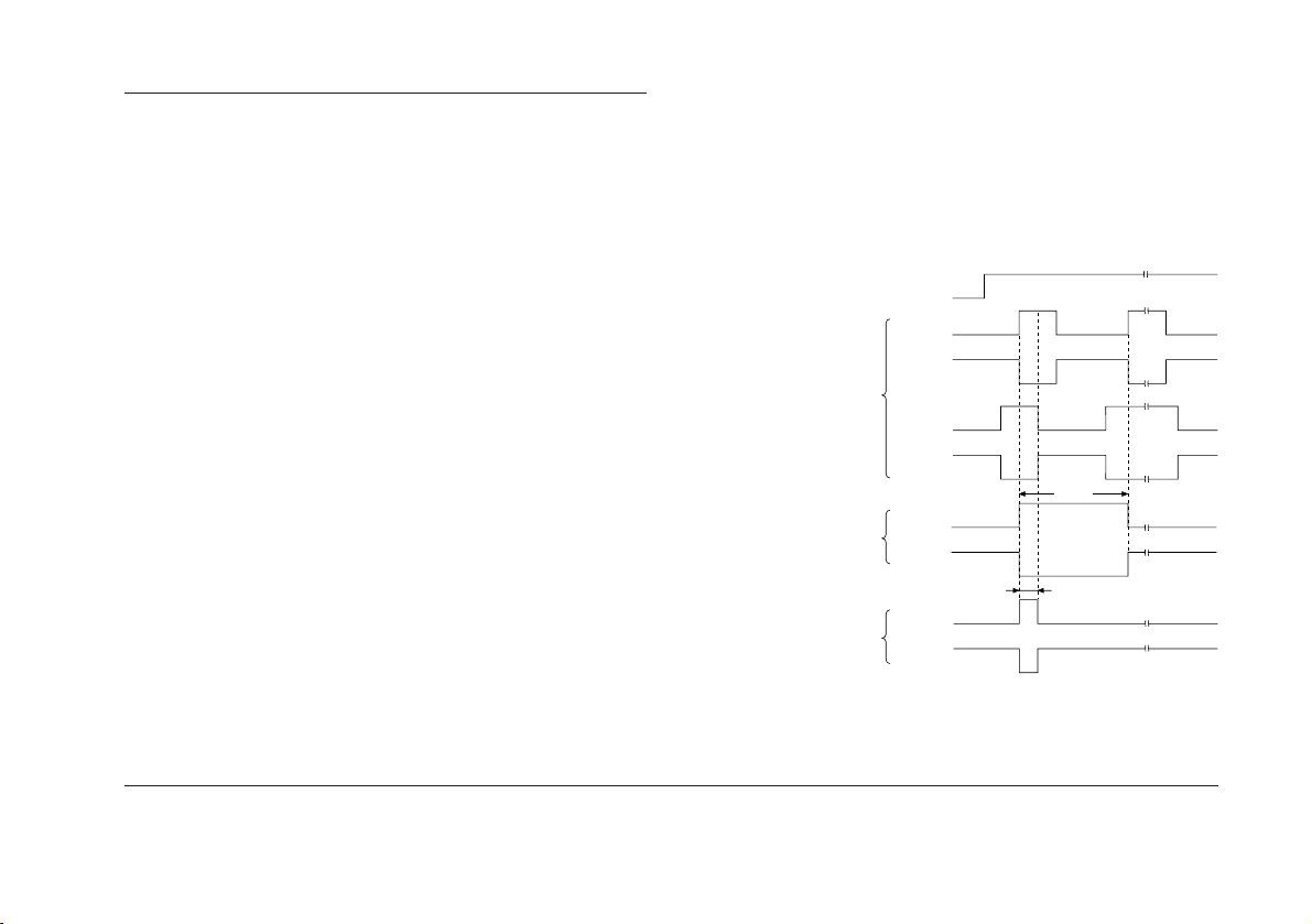
PCA
*PCA
PCB
*PCB
PCZ
*PCZ
PCZ
*PCZ
4Tw
Tw
PL23
Resolution 10 µm/20 µm/50 µm/100 µm (See P.19)
Minimum phase difference (Tw)
Connectable reference point sensor
Output signal and Zero point output signal
Note
The displacement is detected about every 100 µs to generate pulses corresponding to
the displacement of the scale or head.
As the A/B output or Up/Down output signal, unlike common rotary encoder, is artificially
2.5 µs/5 µs/10 µs/20 µs
SET-P15-1 (option)
Note
The reference point signal output is in synch with
the output pulse.
By selecting with the switch on the board (see
Fig.3-3, S201 No.1, A/AB), the signals as shown
are output. The reference point signal is
generated in both directions the scale moves but
should only be used unidirectionally. Make sure
the LED lights upon detecting the reference point.
Reference point input signal
Output pulse
Reference point output pulse
When S201 No.1 is set to A:
Pulse width = 4 x Tw
When S201 No.1 is set to AB:
Pulse width = 1 x Tw
generated, it is sometimes output at the present pulse width (Tw) even when the scale
movement is slow. It is necessary to use a receiving circuit that can receive the present
pulse width.
29
Page 32
Alarm signal If the scale exceeds the maximum response speed
or if a head cable connection becomes open, an
alarm is triggered. When an alarm is triggered, the
ALARM output goes high (the *ALARM output goes
LOW). At this time, the output signal except the
reference point assumes high impedance state.
Alarm clearing
To reset the alarm, remove all the causes of the
alarm and perform a reset or remove power and
apply power once again.
With the alarm triggered, if the external reset is
begin applied, the alarm signal will not be output
and outputs will not go into the high-impedance
state. However, the output signals will be stopped.
Reset To perform a reset, short pins 20 and 7 of the output
connector.
External reset signal input
Maximum reset time: 300 ms
Maximum short-circuit current: 0.5 mA
Maximum operation reset time: 10 ms
(after the reset is canceled)
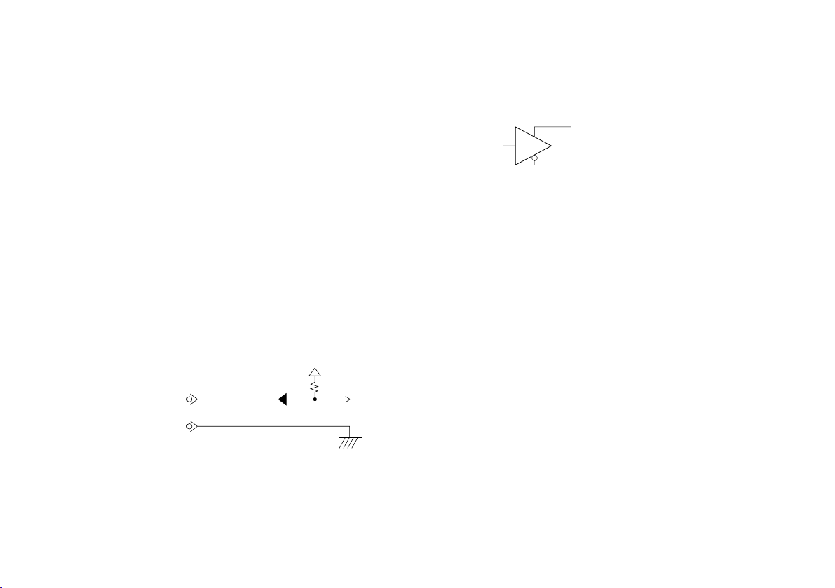
External reset signal input circut
P20:RES
P7:GND
Output circuit
Voltage-differential drivers (SN75113) are used to
produce outputs. Therefore use voltage-differential
line receivers (SN75115 or equivalent) to receive
those outputs.
Signals PCA, PCB, PCZ and ALARM
Signals *PCA, *PCB, *PCZ and *ALARM
Reference point accuracy
1 pulse/4 pulses (selectable)
Ex. : When the resolution is set to 10 µm, the accuracy
is selectable between 10 µm and 40 µm.
Power requirements
DC +5 V (±5%)
Power consumption
2 W (Max.)
Operating temperature range
0 to +45 °C/32 to 113 °F
Storage temperature range
−10 to +50 °C/14 to 122 °F
Head cable length
10 m (PL23-AF), 3 m (PL23-3F)
Total weight PL23-AF: 1030 g/2.318 lb
PL23-3F : 620 g/1.395 lb
Accessories Head installation screws (M4×20) ............... 2 pcs.
Detector installation screws (M4×10) .......... 4 pcs.
Cable clamp screws (M4×8) ........................ 3 pcs.
Techinical Information ................................... 1 pc.
Output connector ........................................... 1 set
Instruction manual ......................................... 1 pc.
Cable clamps ............................................... 3 pcs.
Spacer ............................................................ 1 pc.
30
Page 33
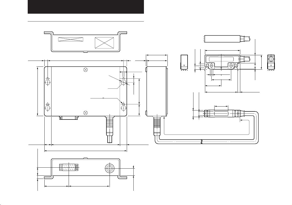
5. DIMENSIONS
PL21/PL22
92/3.62"
12/0.47"
5/0.19" 1.6/0.63"
138/5.43"6/0.24"
Bohrung 2-Ø4.6
126/4.96"
150/5.91"
75/2.95"45/1.77"
Hole
Hole
Loch
2-Ø4.6 hole
2-Ø406 hole
(6)/(0.24")
Ø8
(1.9)
(0.07")
4.6/0.18"
6.5
0.26"
21
(12)/(0.47")
13/0.51"
(38.9)/(1.53")
37/1.46"
50/1.97"
0.83"
63/2.48"
7/0.28"
6/0.24"
4.5/0.18"
35/1.38"
29.5
1.16"
59/2.32"
28.6/1.13"
7.6/0.3"
12/0.47"
Cable length:3/9.8',10/32.8'(m/feet)
Kabellänge:3(m),10(m)
Cable length:3/9.8', 10/32.8'(m/feet)
15/0.59"
1
0.04"
(4)/(0.16")
Unit : mm/inch
26.5
1.04"
31
Page 34
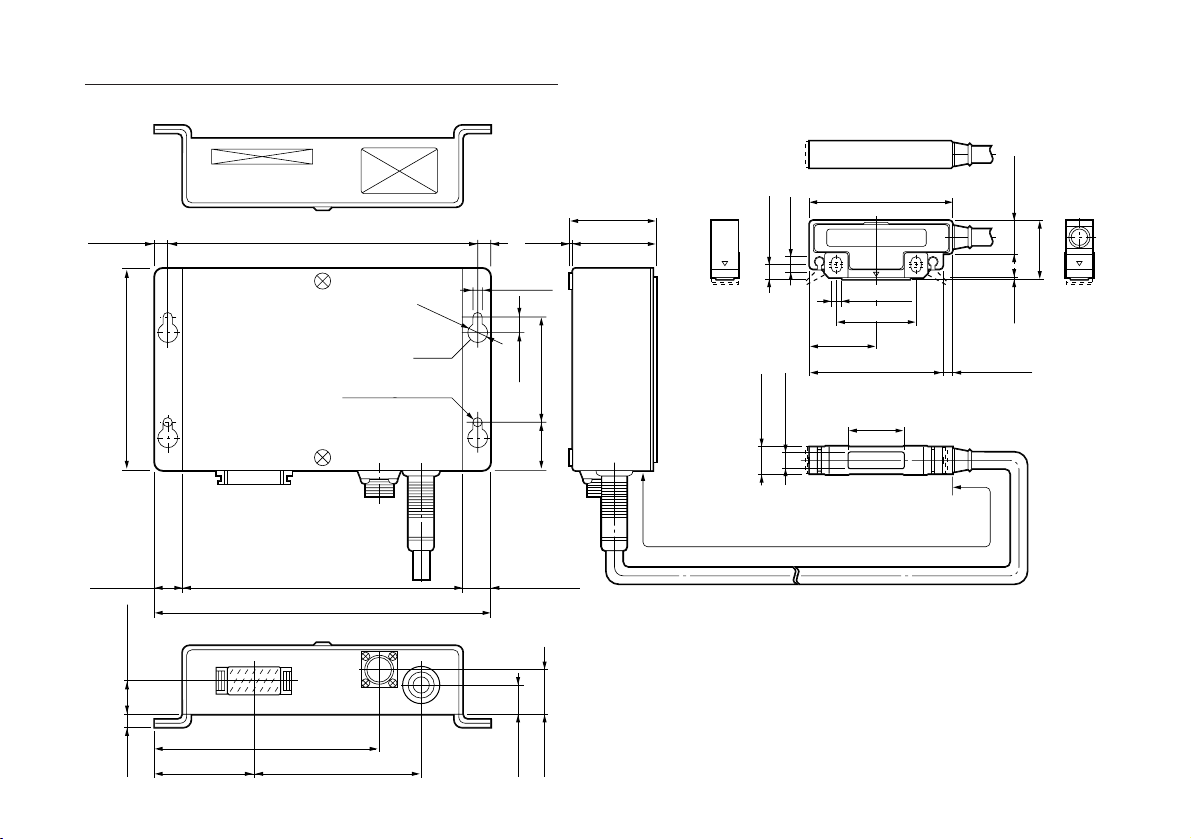
PL23
32
92/3.62"
12/0.47"
5/0.19" 1.6/0.63"
45/1.77"
138/5.43"6/0.24"
126/4.96"
150/5.91"
102/4.02"
75/2.95"
Ø8/Ø0.29"
Hole
Hole
Loch
2-Ø0.18"hole
2-Ø406 hole
Bohrung 2-Ø4.6
(6)/(0.24")
4.6/0.18"
(12)/(0.47")
(1.9)
(0.07")
6.5
0.26"
21
13/0.51"
20/0.79"
(38.9)/(1.53")
37/1.46"
50/1.97"
0.83"
63/2.48"
7/0.28"
6/0.24"
4.5/0.18"
35/1.38"
29.5
1.16"
59/2.32"
28.6/1.13"
7.6/0.3"
12/0.47"
Cable length:3/9.8',10/32.8'(m/feet)
Kabellänge:3(m),10(m)
Cable length:3/9.8', 10/32.8'(m/feet)
15/0.59"
26.5
1
0.04"
(4)/(0.16")
Unit : mm/inch
1.04"
Page 35

Inhaltsverzeichnis 1. Hinweise für den Benutzer
1. Hinweise fÜr den benutzer ..................................... 33
1-1. Allgemeine Vorsichtsmaßnahmen ..................... 33
1-2. Allgemein Hinmeise für den Betrieb .................. 34
1-3. Installation ......................................................... 34
2. Einleitung ................................................................. 34
3. Betrieb ......................................................................35
3-1. Einstellung der Auflösung und der
Ausgangsimpulsbreite ....................................... 35
3-2. Installation des Lesekopfes ............................... 37
3-3. Installation des Bezugspunkts
und Betriebsprüfung (PL23) .............................. 38
3-4. Installation des Detektors .................................. 39
3-5. Bezugspunktsignal-Eingangsanschluß (PL23) .. 39
3-6. Signalausgang ................................................... 40
4. Technische Daten .................................................... 42
PL21 .......................................................................... 42
PL22 .......................................................................... 43
PL23 .......................................................................... 45
5. Abmessungen .......................................................... 47
PL21/PL22................................................................. 47
PL23 .......................................................................... 48
Lesen Sie die Anleitung sorgfältig durch, bevor Sie mit dem
Zusammenbau beginnen, und heben Sie die Anleitung zum
späteren Nachschlagen gut auf.
1-1. Allgemeine Vorsichtsmaßnahmen
Beachten Sie bei der Verwendung von Sony Manufacturing
Systems Corporation Produkten stets auch die folgenden
Sicherheitshinweise.
• Vergewissern Sie sich vor und während des Betriebs,
daß die Einheit einwandfrei funktioniert.
• Treffen Sie ausreichende Sicherheitsvorkehrungen für
den Fall, daß es zu Fehlfunktionen kommt.
• Bei Nichteinhaltung der Spezifikationen und bei
Modifizierung des Produktes wird keine Garantie im
Hinblick auf Funktion und Einhaltung der Nenndaten
übernommen.
• Beim kombinierten Einsatz dieser Einheit mit anderen
Geräten können je nach Einsatzbedingungen die in
dieser Anleitung angegebenen Nenndaten und
Funktionen nicht einwandfrei eingehalten werden.
Überzeugen Sie sich vor der Inbetriebnahme, daß
Kompatibilität besteht.
33
Page 36

2. Einleitung
1-2. Allgemeine Hinweise für den Betrieb
Um Störungen durch andere Anlagen zu vermeiden,ist bei
der Installation des Digirulers auf folgendes zu achten.
1. Treffen Sie alle notwendigen Maßnahmen, um
Störungen durch Relaisschalter, Elektromagneten und
Motor zu vermeiden.
2. Um Störungen der Digiruler-Stromzufuhr zu verhinden,
sollten auch hier vorbeugende Maßnahmen getroffen
werden.
3. Schützen Sie das Ausgangskabel des A/B Signals
gemäß der Bedienungsanleitung (Seite 41).
Benutzen Sie zum Schutz der Digiruler-Geräte ein
Erdungskabel, oder schrauben Sie die Geräte an der
Maschine fest.
1-3. Installation
• Betreiben Sie den PL21/PL22/PL23 an einem gut
ventilierten Platz, der eine Temperatur zwischen 0°C und
+45 °C aufweist und keinem prallen Sonnenlicht oder
Wärmequellen ausgesetzt ist.
• Installieren Sie den PL21/PL22/PL23 mindestens 0.5 m
von Störquellen wie Relais und Schalter hoher Leistung,
Hochspannungsquellen usw. entfernt.
• Verlegen Sie das Lesekopfkabel und das
Signalausgangskabel vom Stromversorgungskabel
34
getrennt.
Bei dem PL21/PL22/PL23 handelt es sich um ein DigirulerPositionsmeßgerät, bestehend aus einem MaßstabLesekopf und einem Detektor, die über ein Kabel
verbunden sind. Sobald die Einheit mit Strom versorgt wird,
informiert sie den Benutzer durch Ausgangsignale über
Position und Verschiebung. Durch Verbinden des PL21/
PL22/PL23 mit einem getrennt erhältlichen Maßstab der
SL100-Serie kann man auf einfache Weise ein Positionsund Verschiebungs-Meßsystem zusammenstellen.
Die PL21/PL22/PL23-Einheit kann auch zusammen mit
älteren Digiruler-Maßstäben verwendet werden, wobei
dann jedoch die Genauigkeit des jeweiligen Maßstabs für
das System maßgebend ist.
Merkmale
• Lesekopf und Maßstab berühren sich nicht und bieten
eine ausgezeichnete Vibrations- und Stoßfestigkeit.
• Der PL21/PL22/PL23 wird nur sehr gering durch äußere
Magnetfelder beeinflußt, und Lesekopftoleranzen wirken
sich nicht auf die Meßpräzision aus.
• Lesekopf und Detektor sind direkt über ein Kabel
miteinander verbunden. Die Teile brauchen nur in das
betreffende Gerät installiert und mit Strom versorgt zu
werden, um die Meßwerte in Form von Impulsen
auszugeben.
• Der PL21 arbeitet mit 12-V-Gleichstrom.
• Der PL22/PL23 arbeitet mit 5-V-Gleichstrom.
• Die wählbare Minimalauflösung ist 10 mm.
• Ein Bezugspunkt kann eingegeben werden, das zum A/
AB-Phasen-Signal synchron ist. (PL23)
Page 37
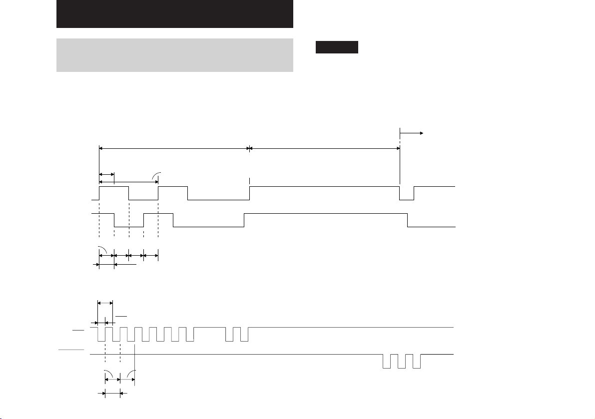
3. Betrieb
3-1. Einstellung der Auflösung und der
Ausgangsimpulsbreite
Die Auflösung des Detektors ist werksseitig auf 10 µm und
die Impulsbreite auf 20 µs voreingestellt.
Siehe hierzu die folgende Abbildung:
Spezifikation des A/B-Ausgangssignals
100μs
≅≅
Tw: Minimale Phasendifferenz: 20 µ s (PL21:20 µ s-0.9 µ s)
4Tw: Minimale Periodendauer: 80µ s
A
B
10μm
Spezifikation der UP/DOWN-Ausgangsimpulse (PL21/PL22)
UP
10μ10μ10μ
Auflösung
Tw
Tw
2
Minimaler Wiederholzyklus: 20 µ s
Impulsbreite: (PL21)10 µ s+0.9 µ s, (PL22)10 µ s
Hinweis (PL21)
Der Kompensationswert von 0,9 µs für die minimale
Phasendifferenz und die Impulsbreite hängen von der
Ausgangslast (Kabellänge, Eingangsschaltkreis des
angeschlossenen Geräts usw.) ab. Bei Einstellung der
minimalen Phasendifferenz und der Impulsbreite auf 2,5 µs
ist eine Ausgangslast von 1 k Ohm oder weniger
erforderlich.
100μs
Die Phasendifferenz zwischen A-und B-Ausgang ist als eine
Zähleinheit festgelegt (Auflösung).
Umkehrsignal
DOWN
10μm
10μm
Auflösung
Der Augangsimpuls wird eventuell bei jedem Tw ausgegeben,
selbst wenn die Bewegungs-Geschwindigkeit langsam ist.
35
Page 38
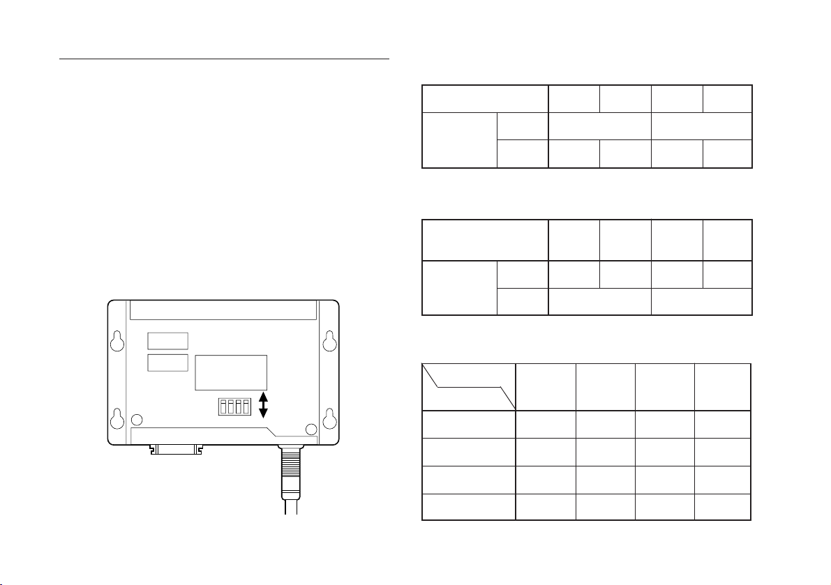
Äuderung der eingestellten Werte
•Schalter-Einstellung für Auflösung:Tabelle 3-1
Zum Ä ndern der Auflö sung und Erhö hen der
Ansprechgeschwindigkeit verfahren Sie wie folgt:
1. Nehmen Sie die Abdeckung ab, indem Sie die beiden
M3 × 6-Schrauben lösen.
2. Stellen Sie den DIP-Schalter auf der Leiterplatte (S101
in Abb. 3-1) entsprechend Tabelle 3-1 und 3-2 ein.
3. Bringen Sie die Abdeckung wieder an und ziehen Sie
die Schrauben fest.
4. Installieren Sie die Einheit im Gerät und überprüfen Sie
die Funktion (Zählerstatus usw.).
S101
OFF
1234
ON
Auflösung (µ m)
SchalterEinstellung
S101-1
S101-2
100
OFF
OFF
50
ON
20
OFF
10
ON
ON
•Schalter-Einstellung für Ansprechgeschwindigkeit:Tabelle 3-2
Tw(µs): Ausgabezyklen
(Kilopulse/Sek.)
SchalterEinstellung
S101-3
S101-4
2,5
(100)
OFF
5
(50)
ON
OFF ON
10
(25)
OFF
20
(12,5)
ON
• Maximale Ansprechgeschwindigkeit (m/min): Tabelle 3-3
Tw(µs)
Auflösung (µ m)
100
50
20
2.5
300
300
300
50
300
300
192
10
300
240
96
20
240
120
48
36
Abb. 3-1
10
192
96
48
24
Page 39
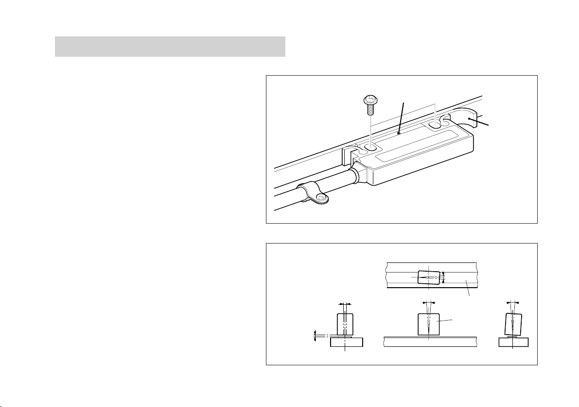
3-2. Installation des Lesekopfes
Der Sensor befindet sich an der mit „∇“ markierten
Stelle des Lesekopfes. Installieren Sie den
Lesekopf so, daß sich das „∇“-Zeichen innerhalb
der effektiven Länge des Maßstabs befindet.
• Fügen Sie das bei der Einheit mitgelieferte
Abstandsstück zwischen die Lesefläche des
Kopfes und des Maßstabes ein und befestigen
Sie den Lesekopf mit den mitgelieferten
Schrauben (M4 × 20).
• Das Anziehmoment sollte 0,7 N·m (7 kg·cm) bis
1,1 N·m (11 kg·cm) betragen.
• Nach der Befestigung des Lesekopfes nehmen
Sie das Abstandsstück heraus.
• Befestigen Sie nach der Installation des Kopfes
das Kabel mit den Kabelklemmen. Vergewissern
Sie sich, daß das Kabel nicht locker ist.
• Die Relativposition von Maßstab und Lesekopf
kann der Abbildung 3-2 entnommen werden.
Toleranz
1,5 mm
(Max.)
±2mm
„∇“-Zeichen
θ
Abb. 3-2
2
<
1
θ
〇
±
0.5
Maßstabfläche
Kopf
Abstandsstück
〇
±
1
3
<
θ
±
3
3
<
θ
〇
37
Page 40
3-3. Installation des Bezugspunkts und
Betriebsprüfung (PL23)
3-3-1. Installation
Richten Sie sich bitte nach der Bedienungsanleitung der
optionellen Einheit SET-P15-1.
Hinweis
Nach Montage bzw. Neueinrichtung von Maßstab, Kopf
und Bezugspunkt die Teile gut festziehen.
S201
D201
S101
Abb. 3-3
AB F
ON
1
2
A
R
3-3-2. Betriebsrüfung
• Führen Sie nach Montage bzw. Neueinrichtung von
Maßstab und Bezugspunkteinheit bitte eine Betriebsprüfung durch.
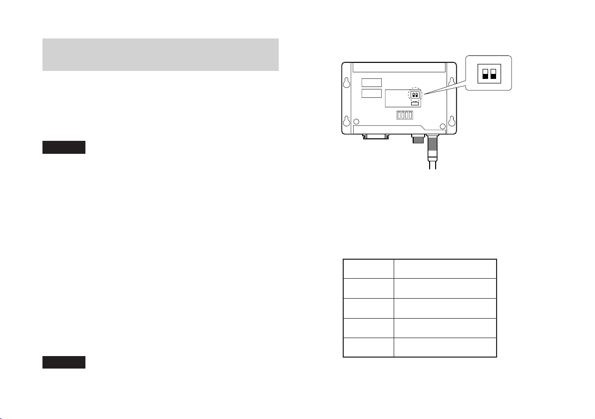
• Nehmen Sie die Abdeckung der Einheit PL23 ab, und
prüfen Sie, ob die LED (Abb. 3-3., D201) bei Passieren
des Bezugspunkts leuchtet. Wenn die LED nicht leuchtet,
verstellen Sie den Schalter (S201 Nr.2, F/R) an der
Platine von F zum R (oder von R zum F), und passieren
dann den Bezugspunkt erneut in derselben Richtung.
Wenn die LED nun leuchtet, funktioniert der Aufbau
einwandfrei. Dann die Abdeckung wieder anbringen.
Hinweis
Sorgen Sie für feste Montage des Bezugspunkts, und
führen Sie die Betriebsprüfung ordnungsgemäß aus. Sonst
38
kann sich der Bezugspunkt verschieben.
3-3-3. Ansprechgeschwindigkeit
• Die Ansprechgeschwindigkeit richtet sich nach der
Auflösung.
Auflösung
100 µ m
50 µ m
20 µ m
10 µ m
Ansprechgeschwindigkeit
30 m / min
15 m / min
6 m / min
3 m / min
Tabelle 3-4
Page 41
3-4. Installation des Detektors
3-5. Bezugspunktsignal-
Eingangsanschluß (PL23)
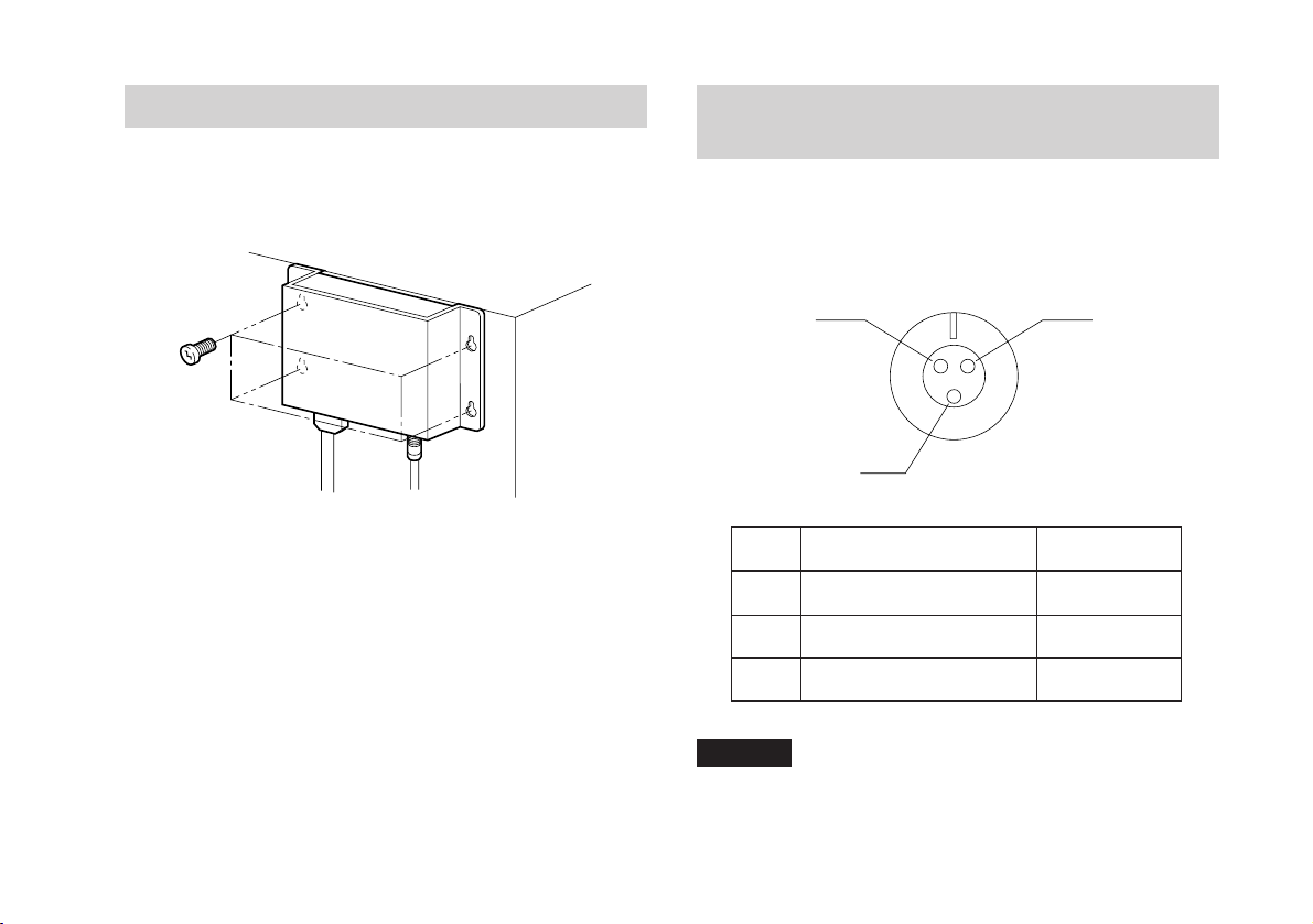
Die Befestigung des Detektors erfolgt mit vier Schrauben
(+PS M4 × 10).
Abb. 3-4
Verwendete Anschlüsse: (Tajimi Musen)
R03-RB3F-Buchse
R03-RB3M-Stecker (mitgeliefert)
A
B
Nr.
Stromversorgung (+Vcc)
A
B
Ausgangssignal
C
Stromversorgung (0V)
Signal
C
Kabelfarbe
rot
weiß
schwarz
Hinweis
Die Abschirmung mit dem Mantel der Steckverbindung
verbinden.
39
Page 42
3-6. Signalausgang
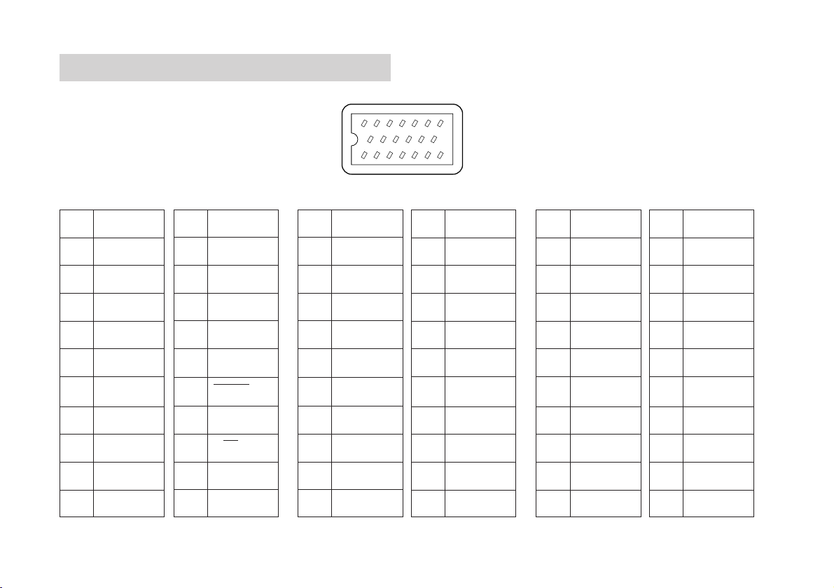
Verwendete Anschlüsse: (Honda Tsushin)
MR-20 RMAG-Buchse
MR-20LF-Stecker (mitgeliefert)
PL21 PL22 PL23
Nr.
Signal
Nr.
Signal
Nr.
13 12 11 10 9 8
Signal
Nr.
14151617181920
2134567
Signal
No.
Signal
Nr.
Signal
1
2
3
4
5
6
7
8
9
10
× → Anschluß verboten: Die mit „Anschluß verboten“ gekennzeichneten Stifte dürfen nicht
40
0V
0V
0V
+12V
+12V
+12V
GND
×
×
×
11
12
13
14
15
16
17
18
19
20
×
ALARM
×
×
×
DOWN/PCA
×
UP/PCB
×
×
10
1
2
3
4
5
6
7
8
9
0V
0V
0V
+5V
+5V
+5V
GND
×
×
×
11
12
13
14
15
16
17
18
19
20
×
ALARM
*ALARM
×
×
*PCD/PCA
PCD/*PCA
*PCU/PCB
PCU*PCB
RESET
verdrahtet werden.
10
1
2
3
4
5
6
7
8
9
0V
0V
0V
+5V
+5V
+5V
GND
×
×
×
11
12
13
14
15
16
17
18
19
20
×
ALARM
*ALARM
PCZ
*PCZ
PCA
*PCA
PCB
*PCB
RESET
Page 43
Ausgangsimpulse
Signal-Ausgangskabel
Verwenden Sie zum Anschluß ein abgeschirmtes Kabel
entsprechend der folgenden Abbildung. Das eine Ende des
Kabels ist an das Detektorgehäuse anzuschließen.
PL21/PL22/PL23
Querschnitt des Kabels
Mantel
PL22/PL23
PL22
A/B-Phase, Alarm
oder up/down,
Alarm
• Einen Baustein SN75115 (o.ä) als Empfangsschaltung
verwenden.
• Erfolgt die Stromversorgung über den
Ausgangssteckverbinder, sicherstellen, daß die
Spannung am Eingang von PL22/PL23 +5 V ±5%
beträgt.
50 m oder weniger
(Siehe Hinweis unten)
Angeschlossenes
Gerät
Abschirmung
PL23
A/B-Phase,
Bezugspunkt,
Wickeldraht dicker als
AWG 28
+5V
0V
Hinweis
Zur Verbesserung der Rauschfestigkeit das
Ausgangskabel kurzschließen.
41
Page 44
4. Technische Daten
6.仕様
PL21
(ON)
(ON)
Hinweis1
(OFF)
(OFF)
(OFF)
(OFF)
(ON)
(ON)
Auflösung 10 µm, 20 µm, 50 µm, 100 µm
Minimale Phasendifferenz (Tw)
PL21-3F, AF:
2.5 µs, 5 µs, 10 µs, 20 µs (–0,9 µs
Minimaler Wiederholzyklus (Tw)
PL21-UF, AU:
2.5 µs, 5 µs, 10 µs, 20 µs (+0,9 µs
Ausgangssignal
Hinweis 3
PL21-3F, AF
A
B
(ON)
PL21-3U, AU
UP
UP
DOWN
DOWN
Alarmsignal Falls der Maß stab die maximale
Ansprechgeschwindigkeit überschreitet, oder falls eine
Unterbrechung in einer Lesekopf-Kabelverbindung
entsteht, wird ein Alarm ausgelöst. Der Alarmausgang
ist während des normalen Betriebs aktiviert (ON) und
bei einer Alarmauslösung deaktiviert (OFF). Durch
Aus- und erneute Einschaltung der Stromversorgung
kann der Alarm zurückgesetzt werden.
Hinweis 1
Empfängt stets das UP/DOWN-Ausgangssignal des UP/DOWN-Zählers.
Wenn nur ein Ausgang verwendet wird, ist keine genaue Messung möglich.
Hinweis 2
42
Der Wert hängt von der Länge des Verbindungskabels und dem Eingangs-Schaltkreis
ab.
(Siehe Seite 35)
Hinweis2
Hinweis2
(ON)
(OFF)
(OFF)
Ausgangs-Schaltkreis Offener Kollektor
max. Nennspannung: 25 V
max. Nennstrom: 50 mA
A, B, ALARM
UP, DOWN
)
)
Stromversorgung DC +12 V (±5%)
Stromaufnahme 0.8 W (max.)
Betriebstemperaturbereich
0 bis +45°C/32 bis 113°F
Lagerungstemperaturbereich
–10 bis +50°C/14 bis 122°F
Lesekopf-Kabellänge
10 m (PL21-AF, AU), 3 m (PL21-3F, 3U)
Gesamtgewicht Ca. 1030 g/2.318 lb (PL21-AF, AU)
Ca. 620 g/1.395 lb (PL21-3F, 3U)
Zubehör Kopf-Montageschrauben (M4 × 20) ........... 2
Detektor-Montageschrauben (M4 × 10) ..... 4
Schrauben für Kabelklemmen (M4 × 12) .. 3
Anleitung ..................................................... 1
Ausgangsanschluß ..................................... 1
Bedienungsanleitung .................................. 1
Kabelklemmen ............................................ 3
Abstandsteil ................................................. 1
Hinweis 3
Die Verschiebung wird nach jeweils 100 µs registriert, um Impulse entsprechend der
Verschiebung des Maßstabes oder des Lesekopfes zu generieren.
Da das A/B- oder UP/DOWN-Ausgangssignal im Gegensatz zu herkömmlichen
Rotations-Encodern künstlich generiert wird, erfolgt die Ausgabe manchmal am
voreingestellten Tw, selbst wenn die Maßstab-Bewegungsgeschwindigkeit gering ist.
Der Empfangs-Schaltkreis muß für die eingestellte Impulsbreite ausgelegt sein.
Page 45
PL22
Auflösung 10 µm, 20 µm, 50 µm, 100 µm
Minimale Phasendifferenz (Tw)
Minimaler Wiederholzyklus (Tw)
Ausgangssignal
PL22-AF, AU: 2,5 µs, 5 µs, 10 µs, 20 µs
PL22-3F, 3U: 2,5 µs, 5 µs, 10 µs, 20 µs
Hinweis 2
PL22-AF, AU
PCA
*PCA
PCB
*PCB
PL22-3F, 3U
PCU
*PCU
PCD
*PCD
Hinweis1
(Siehe Seite 35)
Alarmsignal Wenn der Maß stab die maximale
Ansprechgeschwindigkeit überschreitet oder
z.B. das Kopfkabel abgetrennt ist, wird ein Alarm
ausgelöst. Bei einem Alarm wechselt Ausgang
ALARM auf „H“ (Ausgang * ALARM auf „L“).
Gleichzeitig werden alle Ausgänge hochohmig.
Alarmrücksetzung Zum Rü cksetzen des Alarms alle
Störungsursachen beseitigen und das Gerät
rücksetzen oder die Stromversorgung ausund wieder einschalten.
Wird bei ausgelöstem Alarm eine externe
Rücksetzung ausgeführt, erfolgt kein
Alarmsignal, und die Ausgänge wechseln
nicht auf hochohmigen Zustand. Die
Ausgangssignalausgabe wird unterdrückt.
Rücksetzung Zum Rücksetzen die Anschlüsse 20 und 7 des
Ausgangssteckverbinders kurzschließen.
Externes Rücksetzsignal
Maximale Rücksetzzeit: 300 ms
Maximaler Kurzschlußstrom: 0,5 mA
Maximale Zeit bis zur Betriebsaufnahme: 10 ms
(nach Aufheben des Rücksetzzustands)
Externe Rücksetzung Eingangs-Schalkreis
P20:RES
P7:GND
Hinweis 1
Der Wert hängt von der Länge des Verbindungskabels und dem Eingangs-Schaltkreis
ab.
Hinweis 2
Die Verschiebung wird nach jeweils 100 µs registriert, um Impulse entsprechend der
Verschiebung des Maßstabes oder des Lesekopfes zu generieren.
Da das A/B- oder UP/DOWN-Ausgangssignal im Gegensatz zu herkömmlichen
Rotations-Encodern künstlich generiert wird, erfolgt die Ausgabe manchmal am
voreingestellten Tw, selbst wenn die Maßstab-Bewegungsgeschwindigkeit gering ist.
Der Empfangs-Schaltkreis muß für die eingestellte Impulsbreite ausgelegt sein.
43
Page 46

Ausgangs-Schaltkreis
Die Ausgangsspannungen werden von
Differenzspannungs-Leitungstreibern
(SN75113) geliefert. Daher sind
empfangsseitig entsprechende
Differenzspannungs-Leitungsempfänger zu
verwenden.
Signale PCA, PCB und ALARM bzw PCU, PCD und ALARM
Signale *PCA, *PCB und *ALARM bzw *PCU, *PCD und *ALARM
Stromversorgung DC +5 V (± 5%)
Stromaufnahme 2 W (max.)
Betriebstemperaturbereich
0 bis +45°C/32 bis 113°F
Lagerungstemperaturbereich
–10 bis +50°C/14 bis 122°F
Lesekopf-Kabellänge
10 m (PL22-AF, AU), 3 m (PL22-3F, 3U)
Gesamtgewicht Ca. 2.318 lb (PL22-AF, AU)
Ca. 1.395 lb (PL22-3F, 3U)
Zubehör Kopf-Montageschrauben (M4 × 20) ........... 2
Detektor-Montageschrauben (M4 ×10) ...... 4
Schrauben für Kabelklemmen (M4 × 8) .... 3
Anleitung ..................................................... 1
Ausgangsanschluß ..................................... 1
Bedienungsanleitung .................................. 1
Kabelklemmen ............................................ 3
Abstandsteil ................................................. 1
44
Page 47
PCA
*PCA
PCB
*PCB
PCZ
*PCZ
PCZ
*PCZ
4Tw
Tw
PL23
Auflösung 10 µm, 20 µm, 50 µm, 100 µm (Siehe Seite 35)
Minimale Phasendifferenz (Tw)
Anschließbarer Bezugspunkt-Sensor
Ausgangssignale und Bezugspunktausgangssignal
PL23-AF: 2,5 µs, 5 µs, 10 µs, 20 µs
SET-P15-1 (option)
Hinweis
Das Bezugspunktsignal wird synchron zu den
Ausgangsimpuls erzeugt.
Bei Auswahl mit dem Schalter (sieh Abb. 3-3,
S201, Nr.-1,A/AB) auf der Schaltkarte wird die
angezeigten Signale erzeugt. Obwohl das
Bezugspunktsignal bei beiden Richtungen der
Maßstabsbewegung erzeugt wird, ist das nur in
einer einzigen Richtung zu benutzen.
Sicherstellen, daß die Leuchtdiode bei
Erfassung des Bezugspunkts aufleuchtet.
Bezugspunkteingangssignal
Ausgangsimpuls
Bezugspunktausgangsimpuls
Wenn S201 Nr. 1 auf Seit
A gestellt wird:
Impulsdauer = 4 x Tw
Hinweise
Die Verschiebung wird nach jeweils 100 µs registriert, um Impulse entsprechend der
Verschiebung des Maßstabes oder des Lesekopfes zu generieren.
Da das A/B- oder UP/DOWN-Ausgangssignal im Gegensatz zu herkömmlichen
Wenn S201 Nr.1 auf Seit
AB gestellt wird:
Impulsdauer = 1 x Tw
Rotations-Encodern künstlich generiert wird, erfolgt die Ausgabe manchmal am
voreingestellten Tw, selbst wenn die Maßstab-Bewegungsgeschwindigkeit gering ist.
Der Empfangs-Schaltkreis muß für die eingestellte Impulsbreite ausgelegt sein.
45
Page 48
Alarmsignal Wenn der Maß stab die maximale
Ansprechgeschwindigkeit überschreitet oder
z.B. das Kopfkabel abgetrennt ist, wird ein Alarm
ausgelöst. Bei einem Alarm wechselt Ausgang
ALARM auf „H“ (Ausgang * ALARM auf „L“).
Gleichzeitig werden alle Ausgänge außer dem
Bezugspunkt hochohmig.
Alarmrücksetzung Zum Rü cksetzen des Alarms alle
Störungsursachen beseitigen und das Gerät
rücksetzen oder die Stromversorgung ausund wieder einschalten.
Wird bei ausgelöstem Alarm eine externe
Rücksetzung ausgeführt, erfolgt kein
Alarmsignal, und die Ausgänge wechseln
nicht auf hochohmigen Zustand. Die
Ausgangssignalausgabe wird unterdrückt.
Rücksetzung Zum Rücksetzen die Anschlüsse 20 und 7 des
Ausgangssteckverbinders kurzschließen.
Externes Rücksetzsignal
Maximale Rücksetzzeit: 300 ms
Maximaler Kurzschlußstorm: 0,5 mA
Maximale Zeit bis zur Betriebsaufnahme: 10 ms
(nach Aufheben des Rücksetzzustands)
Externe Rücksetzung Eingangs-Schalkreis
P20:RES
P7:GND
Ausgangs-Schaltkreis
Die Ausgangsspannungen werden von
Differnzspannungs-Leitungstreibern
(SN75113) geliefert. Daher sind
empfangsseitig entsprechende
Differenzspannungs-Leitungsempfänger zu
verwenden.
Signale PCA, PCB, PCZ, ALARM und ALARM
Signale *PCA, *PCB, *PCZ, *ALARM und *ALARM
Bezugspunktgenauigkeit
1 Impuls und 4 Impulse (wählbar)
Z.B. : Bei Auflösung von 10 µm ist die Genauigkeit
zwischen 10 µm und 40 µm wählbar.
Stromversorgung DC +5 V (±5%)
Stromaufnahme 2 W (max.)
Betriebstemperaturbereich
0 bis +45°C/32 bis 113°F
Lagerungstemperaturbereich
–10 bis +50°C/14 bis 122°F
Lesekopf-Kabellänge
10 m (PL23-AF), 3 m (PL23-3F)
Gesamtgewicht Ca. 1030 g/2.318 lb (PL23-AF)
Ca. 620 g/1.395 lb (PL23-3F)
Zubehör Kopf-Montageschrauben (M4 × 20) ........... 2
Detektor-Montageschrauben (M4 ×10) ...... 4
Schrauben für Kabelklemmen (M4 × 8) ..... 3
Anleitung ..................................................... 1
Ausgangsanschluß ..................................... 1
Bedienungsanleitung .................................. 1
Kabelklemmen ............................................ 3
Abstandsteil ................................................. 1
46
Page 49
5. Abmessungen
PL21/PL22
92/3.62"
12/0.47"
5/0.19" 1.6/0.63"
138/5.43"6/0.24"
Bohrung 2-Ø4.6
126/4.96"
150/5.91"
75/2.95"45/1.77"
Hole
Loch
2-Ø4.6 hole
(6)/(0.24")
Ø8
(1.9)
(0.07")
4.6/0.18"
6.5
0.26"
21
(12)/(0.47")
13/0.51"
(38.9)/(1.53")
37/1.46"
50/1.97"
0.83"
63/2.48"
7/0.28"
6/0.24"
4.5/0.18"
35/1.38"
29.5
1.16"
59/2.32"
28.6/1.13"
7.6/0.3"
12/0.47"
Cable length:3/9.8',10/32.8'(m/feet)
Kabellänge:3(m),10(m)
15/0.59"
26.5
1.04"
1
0.04"
(4)/(0.16")
Einheit: mm/Zoll
47
Page 50
PL23
48
92/3.62"
12/0.47"
5/0.19" 1.6/0.63"
45/1.77"
138/5.43"6/0.24"
126/4.96"
150/5.91"
102/4.02"
75/2.95"
Ø8/Ø0.29"
Hole
Loch
2-Ø0.18"hole
Bohrung 2-Ø4.6
(6)/(0.24")
4.6/0.18"
(12)/(0.47")
(1.9)
(0.07")
6.5
0.26"
21
13/0.51"
20/0.79"
(38.9)/(1.53")
37/1.46"
50/1.97"
0.83"
63/2.48"
7/0.28"
6/0.24"
4.5/0.18"
35/1.38"
29.5
1.16"
59/2.32"
28.6/1.13"
7.6/0.3"
12/0.47"
Cable length:3/9.8',10/32.8'(m/feet)
Kabellänge:3(m),10(m)
15/0.59"
26.5
1.04"
1
0.04"
(4)/(0.16")
Einheit: mm/Zoll
Page 51
お
客
様
保
証
フリガナ
お
名
前
〒 電話 - -
ご
住
所
お買上げ日
期
間
本 体 1
型
名
年月日
PL21/PL22/PL23
お買上げ店住所・店名
年
保 証 書
様
保証規定
1 保証の範囲
1 取扱説明書、本体添付ラベル等の注意書に従った正
常な使用状態で、保証期間内に故障した場合は、無
償修理いたします。
2 本書に基づく保証は、本商品の修理に限定するもの
とし、それ以外についての保証はいたしかねます。
2 保証期間内でも、次の場合は有償修理となります。
1 火災、地震、水害、落雷およびその他天災地変によ
る故障。
2 使用上の誤りおよび不当な修理や改造による故障。
3 消耗品および付属品の交換。
4 本書の提示が無い場合。
5 本書にお買い上げ日、お客様名、販売店名等の記入
が無い場合。(ただし、納品書や工事完了報告書が
ある場合には、その限りではありません。)
3 離島、遠隔地への出張修理および持込修理品の出張修理
については、出張に要する実費を別途申し受けます。
電話 - -
本書はお買上げ日から保証期間中に故障が発生した場
合には、右記保証規定内容により無償修理を行うこと
をお約束するものです。
印
4 本書は日本国内においてのみ有効です。
5 本書の再発行はいたしませんので、紛失しないよう大切
に保管してください。
Page 52

商品についてのお問い合わせ
ソニーマニュファクチュアリングシステムズ株式会社
コールセンター 〒259-1146 神奈川県伊勢原市鈴川45 TEL:0120-55-7973
計測機器営業部 〒259-1146 神奈川県伊勢原市鈴川45 TEL:(0463)92-7971 FAX:(0463)92-7978
サービス課 〒259-1146 神奈川県伊勢原市鈴川45 TEL:(0463)92-2132 FAX:(0463)92-3090
サービス代行店
北海道地区: 札幌 (株)札幌トランジスタ TEL:(011)631-3401
東北、関東、甲信越地区: 東京 (有)保田電機 TEL:(0424)92-9191
東海、北陸地区: 岐阜 カトー商事(株) TEL:(0583)83-6234
近畿、中国、四国地区: 大阪 (有)宮下電機サービス TEL:(06)6724-7005
九州地区: 福岡 三伸エンジニアリング(株) TEL:(092)963-1296
Sony Manufacturing Systems Corporation
Isehara Plant
45 Suzukawa, Isehara-shi, Kanagawa 259-1146 Japan TEL: +81 (463) 92-7971 FAX: +81 (463) 92-7978
Sony Precision Technology America, Inc.
20381 Hermana Circle, Lake Forest, CA 92630, U.S.A. TEL: (949) 770-8400 FAX: (949) 770-8408
Sony Precision Technology Europe GmbH
Heinrich-Hertz-Strasse 1 , 70327 Stuttgart, Germany TEL: (0711) 5858-777 FAX: (0711) 580715
http://www.sonysms.co.jp/
名古屋 〒465-0095 愛知県名古屋市名東区高社2-171 TEL:(052)778-3181 FAX:(052)778-4147
大阪 〒532-0011
大阪府大阪市淀川区西中島2-14-6新大阪第2ドイビル
横浜 (株)ファーストビデオ TEL:(045)582-8649
愛知 (有)カメテック TEL:(0568)72-1435
広島 (株)三田電子 TEL:(082)831-5261
TEL:(06)6305-3101 FAX:(06)6304-6586
ソニーマニュファクチュアリングシステムズ株式会社 〒346-0035 埼玉県久喜市清久町1-10
Sony Manufacturing Systems Corporation 1-10 Kiyoku-cho, Kuki-shi, Saitama 346-0035 Japan
PL21 / PL22 / PL23
2-996-265-65
このマニュアルは再生紙を使用しています。
Printed in Japan
©1995 Sony Manufacturing Systems Corporation
2004.4
 Loading...