

Sony DEG-5, DEG-5-CK, DEG-7 Service manual

D-EG5/EG5CK/EG7
SERVICE MANUAL
Ver 1.2 2001.02
Photo : D-EG7
SPECIFICATIONS
US Model
D-EG7
Canadian Model
D-EG5/EG5CK/EG7
AEP Model
UK Model
E Model
Australian Model
D-EG7
Model Name Using Similar Mechanism NEW
CD Mechanism Type CDM-2911AAA
Optical Pick-up Type DAX-11A2
9-927-107-12
2001B0200-1
© 2001.1
US, Canadian model: 120 V, 60 Hz
AEP, French, German, East European,
E13 model:220 - 230 V, 50/60 Hz
UK model: 230 - 240 V, 50 Hz
Australian model: 240 V, 50 Hz
Sony Corporation
Audio Entertainment Group
General Engineering Dept.
– Continued on page 2 –
PORTABLE CD PLAYER
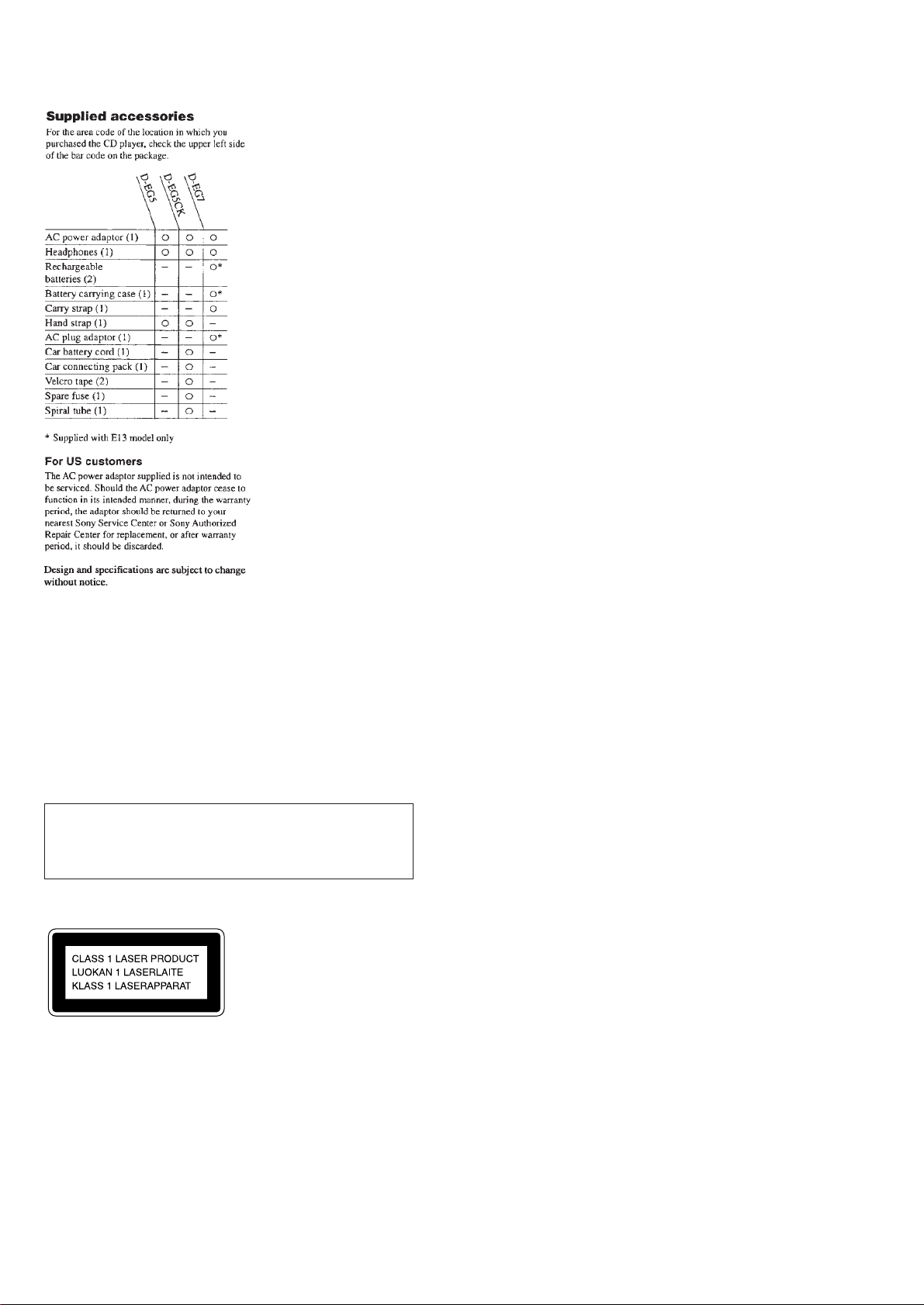
TABLE OF CONTENTS
Specifications ............................................................................ 1
1. SERVICING NOTES.................................................... 3
2. GENERAL
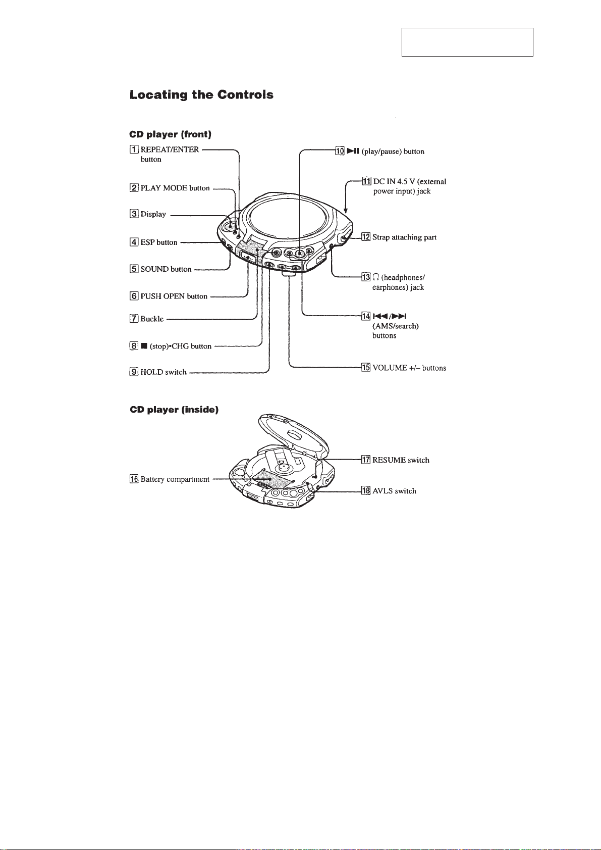
Locating the Controls......................................................... 4
3. DISASSEMBLY
3-1. Upper Lid ASSY......................................................... 5
3-2. Cabinet (Front), Cabinet (Rear).................................. 5
3-3. MD ASSY................................................................... 6
3-4. Spindle Motor (M902), Optical Pick-up,
Sled Motor (M901) ..................................................... 6
3-5. Main Board ................................................................. 6
4. SERVICE MODE........................................................... 7
5. ADJUSTMENS .............................................................. 8
6. DIAGRAMS
6-1. Explanation of IC Terminals......................................11
6-2. Block Diagram.......................................................... 13
6-3. Printed Wiring Boards .............................................. 16
6-4. Schematic Diagram................................................... 19
DANGER
Invisible laser radiation when open and interlock failed or defeated.
Avoid direct exposure to beam.
CAUTION
Use of controls or adjustments or performance of procedures other
than those specified herein may result in hazardous radiation
exposure.
Laser component in this product is capable of emitting
radiation exceeding the limit for Class 1.
This Compact Disc player is
classified as a CLASS 1 LASER
product.
The CLASS 1 LASER
PRODUCT label is located on
the rear exterior.
Flexible Circuit Board Repairing
• Keep the temperature of the soldering iron around 270°C during
repairing.
• Do not touch the soldering iron on the same conductor of the
circuit board (within 3 times).
• Be careful not to apply force on the conductor when soldering or
unsoldering.
7. EXPLODED VIEWS
7-1. Cabinet (Front) Section ............................................ 28
7-2. Cabinet (Rear) Section.............................................. 29
7-3. Optical pick-up Section (CDM-2911AAA).............. 30
8. ELECTRICAL PARTS LIST.................................... 31
SAFETY-RELATED COMPONENT WARNING!!
COMPONENTS IDENTIFIED BY MARK ! OR DOTTED LINE WITH
MARK !ON THE SCHEMATIC DIAGRAMS AND IN THE PARTS
LIST ARE CRITICAL TO SAFE OPERATION.
REPLACE THESE COMPONENTS WITH SONY PARTS WHOSE
PART NUMBERS APPEAR AS SHO WN IN THIS MANUAL OR IN
SUPPLEMENTS PUBLISHED BY SONY.
ATTENTION AU COMPOSANT AYANT RAPPORT
À LA SÉCURITÉ!
LES COMPOSANTS IDENTIFIÉS P AR UNE MARQUE ! SUR LES
DIAGRAMMES SCHÉMATIQUES ET LA LISTE DES PIÈCES
SONT CRITIQUES POUR LA SÉCURITÉ DE FONCTIONNEMENT .
NE REMPLACER CES COMPOSANTS QUE PAR DES PIÈCES
SONY DONT LES NUMÉROS SONT DONNÉS DANS CE MANUEL
OU DANS LES SUPPLÉMENTS PUBLIÉS PAR SONY.
Notes on chip component replacement
• Never reuse a disconnected chip component.
• Notice that the minus side of a tantalum capacitor may be damaged by heat.
– 2 –
SECTION 1
505
R809
806
SERVICING NOTES
NOTES ON HANDLING THE OPTICAL PICK-UP BLOCK OR
BASE UNIT
The laser diode in the optical pick-up block may suffer electrostatic
breakdown because of the potential difference generated by the charged
electrostatic load, etc. on clothing and the human body. During repair,
pay attention to electrostatic breakdown and also use the procedure in
the printed matter which is included in the repair parts.
The flexible board is easily damaged and should be handled with care.
NOTES ON LASER DIODE EMISSION CHECK
The laser beam on this model is concentrated so as to be focused on the
disc reflective surface by the objective lens in the optical pick-up block.
Therefore, when checking the laser diode emission, observe from more
than 30cm away from the objective lens.
Before Replacing the Optical pick-up Block
Please be sure to check thoroughly the parameters as per the “Optical
pick-up Block Checking Procedure” (Part No. : 9-960-027-11) issued
separately before replacing the optical Pick-up block.
Note and specifications required to check are given below.
• FOK output : IC501 !™ pin
When checking FOK, remove the lead wire to disc motor.
• S curve P-to-P value : 0.9 – 1.5Vp-p IC501 #¡ pin. (Connect pin !™
of IC501 (TP880) and 3 of IC501 (GND) with a jumper wire).
When checking S curve P-to-P value, remove the lead wire to disc
motor.
• Adjusted part for focus gain adjustment : RV503
• RF signal P-to-P value : 0.8 – 1.2Vp-p
• Traverse signal P-to-P value : 1.0 – 2.4Vp-p
• The repairing grating holder is impossible.
• Adjusted part for tracking gain adjustment : RV502
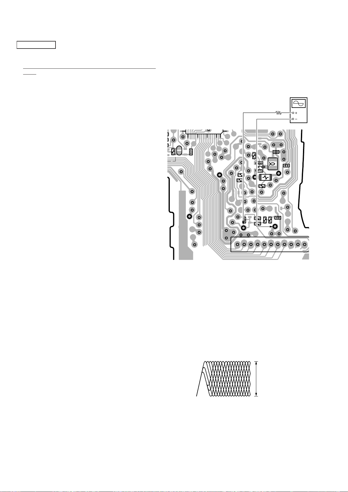
5. Calculate the current value by the reading of the digital voltmeter.
Reading of the tester (V) ÷ 4.7 ( Ω ) = current value (A)
(Example) Reading of the digital voltmeter of 0.2256 V :
0.2256 V ÷ 4.7 Ω = 0.048 (A) = 48 mA
6. Check that the current value is within the following range.
• Current value of the label
Variation by temperature : 0.4mA / °C
Current increases with temperature increased.
Current decreases with temperature decreased.
If the current is more than the range above, there is a trouble in the
automatic power control circuit or the laser diode is in deterioration.
If less than the range, a trouble exists in the automatic power control
circuit or the optical pick-up.
[MAIN BOARD] (Side B)
+5
mA(25°C)
-11
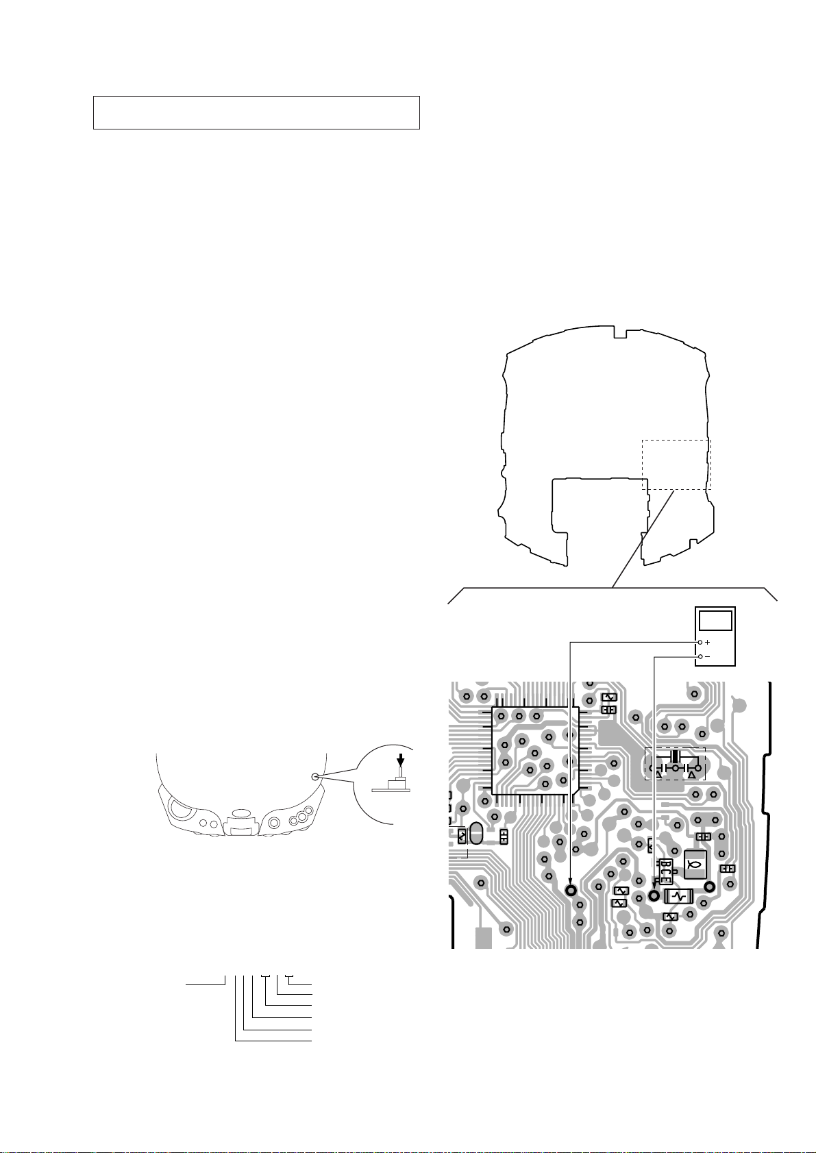
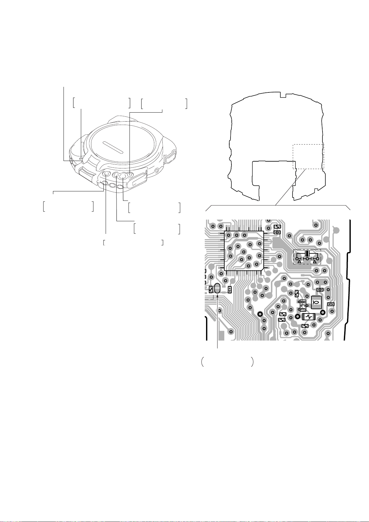
Laser Diode Checking Methods
During normal operation of the equipment, emission of the laser diode
is prohibited unless the upper panel is closed while turning ON the S801
(push switch type).
The following two checking methods for the laser diode are operable.
Method-1 (In the service mode or normal operation) :
Emission of the laser diode is visually checked.
1. Open the upper lid.
2. Push the S801 as shown in Fig. 1-1 .
3. Check the object lens for confirming normal emission of the laser
diode. If not emitting, there is a trouble in the automatic power
control circuit or the optical pick-up. During normal operation, the
laser diode is turned ON about 2.5 seconds for focus searching.
S801
Fig. 1-1 Method to push S801
Method-2 (In the service mode or normal operation) :
Check the value of current flowing in the laser diode.
1. Remove the upper panel.
2. Read the current printed on the rear side of the optical pick-up.
(Print on the rear side of the optical pick-up)
3. Connect a digital voltmeter as shown in Fig. 1-2
4. Press the ^ key.
current value
A : less than 48 mA
AC2211397
year
month
date
shift No.
line No.
version
digital voltmeter
TP506
TP547
19
18
15
10
5
1
TP503
R506
R507
TP
R
C806
TP821
TP511
TP512
TP534
TP508
R510
Q501
TP547
TP555
TP502
X801
TP523
R509
0
37
40
45
50
822
54
55 60 65 70 72
TP816
(TEST)
IC801
C879
3036
25
TP507
TP506
Fig. 1-2 Digital Voltmeter Connecting Location
R505
C516
TP501
C549
L502
TP532
– 3 –
SECTION 2
GENERAL
This section is extracted from
instruction manual.
– 4 –
SECTION 3
Y
DISASSEMBLY
r
The equipment can be removed using the following procedure.
Upper Lid ASSY
Set
Note : Follow the disassembly procedure in the numerical order given.
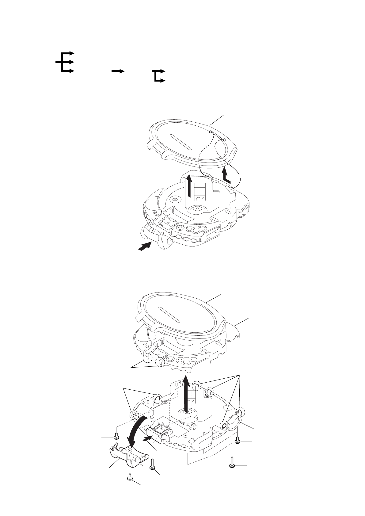
3-1. UPPER LID ASSY
Cabinet (Front)
Cabinet (Rear)
MD ASSY
Spindle motor (M902), Optical Pick-up, Sled motor (M901)
Main board
Upper lid ASS
1
OPEN
3-2. CABINET (FRONT), CABINET (REAR)
3
2
Upper lid ASSY
Cabinet (Front)
2
Screws (B2)
Buckle ASSY
7
6
Claws
Claws
9
5
4
OPEN
1
Screws (B2x10)
3
Screws (B2)
8
Claws
Cabinet (Rear)
2
1
Screws (B2x10)
Screws (B2)
– 5 –
)
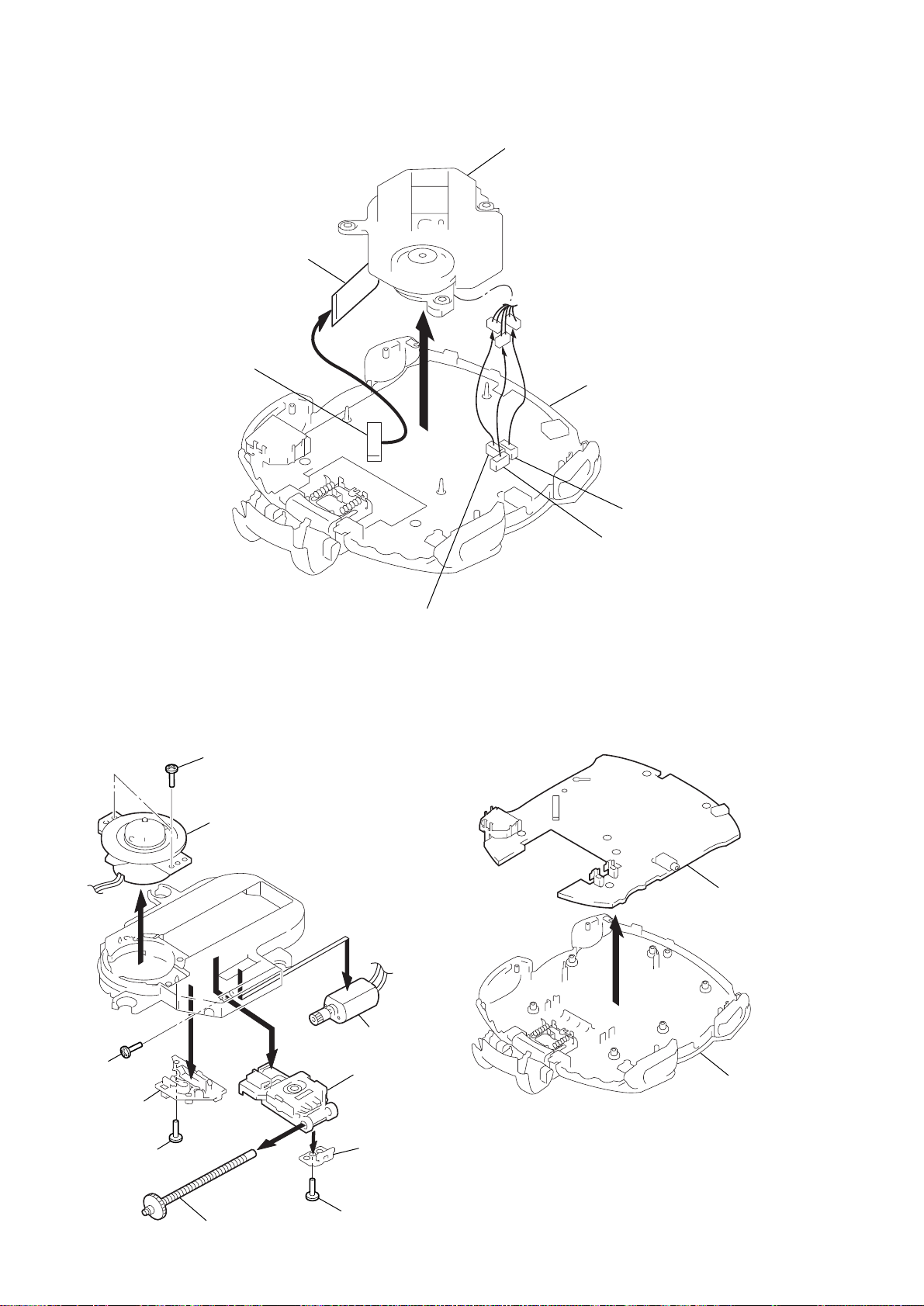
3-3. MD ASSY
)
1
Flexible board
MD ASSY
CN501
3-4. SPINDLE MOTOR (M902), OPTICAL PICK-UP,
SLED MOTOR (M901)
1
Screws (B1.7)
5
2
CN703 (White)
3-5. MAIN BOARD
Cabinet (Rear)
4
CN702 (Red
3
CN701 (Blue)
9
Screws
(+P1.4x2.5)
Spring, sled
3
Screw (B1.7x6)
2
Spindle motor (M902)
4
Screw ASSY, Feed
5
8
!º
7
6
Sled motor
(M901)
Optical pick-up
(DAX-11A2)
Rack
Screw
Main board
1
Cabinet (Rear
– 6 –
SECTION 4
505
R809
806
SERVICE MODE
Service Mode (service program)
The equipment is provided with a service program built in the microcomputer, like conventional models.
Service program operation methods are described in the following.
REPEAT/ENTER
Tracking gain-up mode while pressing
PLAY MODE
Tracking servo and sled
servo are turned ON
HOLD OFF n ON
Be sure to turn OFF
the HOLD switch
(if ON, pressing each key is
deactivated)
p
(STOP)
All servos are turned OFF
+
(FF)
The optical pick-up
is moved outwardly
^
(PLAY/PAUSE)
FOCUS is turned ON
to effect pull in mode
=
(FR)
The optical pick-up
is moved inwardly
Fig. 4-1 Layout of each key
• Step 1 (Service mode setting method)
1. Turn OFF the HOLD switch the external power supply disconnected (power is not applied to the set).
2. Solder across the TP816 (TEST) terminals (pin %™ , IC801 (TEST)
is grounded).
3. Connect an external power supply.
Thus, the set is switched to the service mode.
• Step 2 (Operation in the service mode )
1. Once the service mode is effected, the LCD displays 5 indications each of which is repeatedly displayed.
However, the following operations can be activated even if LCD
indication is effected.
2. By pressing the + or = key, the optical pick-up movable
inwardly or outwardly. However, if this is activated, tracking
servo and sled servo are turned OFF, so it can be turned ON by
pressing the PLAY MODE key, if required.
3. By pressing the REPEAT/ENTER key, the tracking gain-up mode
becomes active.
4. By pressing the ^ key, focus is turned ON from focus searching while entering CLV-S (pull-in mode).
Without disc, focus searching is repeated continuously.
5. By pressing the PLAY MODE key, tracking servo, sled servo
and CLV-A (servo in PLAY) are turned ON.
6. When 4. and 5. are performed, playing begins. No muting is ON
in the service mode.
7. By pressing the p key, all servos (focus tracking and sled) are
turned OFF. However, the disc motor revolves for a while by
inertia.
• Step 3 (Resetting service mode )
1. Be sure to disconnect the external power supply and remove the
solder bridge at the TEST terminals connected in setting.
2. The set thus becomes available for normal operation.
– MAIN BOARD – (Side B)
3036
37
0
40
IC801
45
50
822
54
55 60 65 70 72
C879
TP816
(TEST)
TP506
TP816 (TEST)
Normal mode : Open
Test mode : Short
25
TP507
19
18
15
10
TP503
R506
R507
TP
5
1
R
C806
TP821
TP511
TP512
TP508
TP534
R510
Q501
TP547
TP555
TP502
X801
TP523
R509
R505
C516
TP501
C549
L502
TP532
Fig. 4-2 Location of test terminal
– 7 –
SECTION 5
1
R809
e
ADJUSTMENTS
CD SECTION
Precautions for Adjustment
1. Before beginning adjustment, set the equipment to service mode.
After the completion of adjustment, be sure to reset the service
mode.
For more information, see “Service Mode (service program)”
on page 7.
2. Perform adjustments in the order given.
3. Use the disc (YEDS-18. Part No. 3-702-101-01) unless otherwise indicated.
4. Power supply voltage requirement : DC 4.5 V
HOLD switch : OFF
VOLUME : Minimum
SOUND switch : NORM
AVLS switch : OFF
Before Beginning Adjustment
Set the equipment to service mode (See page 7) and check the following.
If there in an error, repair the equipment.
• Checking of the sled motor
1. Open the upper panel.
2. Press the + and = keys and check that the optical pick-up
can move smoothly without sluggishness or abnormal noise in
innermost periphery n outermost periphery n innermost periphery.
+ : The optical pick-up moves outwardly
= : The optical pick-up moves inwardly
• Checking of focus searching
1. Open the upper panel.
2. Press the ^ key. (Focus searching operation is activated continuously).
3. Check the object lens of the optical pick-up for smooth up/down
motion without sluggishness or abnormal noise.
4. Press the p key.
Check that focus searching operation is deactivated. If not, again
press the p key slightly longer.
Focus Bias Check
Condition :
• Hold the set in horizontal state.
Procedure :
[MAIN BOARD] (Side B)
oscilloscop
(AC range)
Ω
TP533 (VC)
TP523
R509
TP517
R501
2 k
C516
L502
TP532
R505
TP518
C501
R512
TP533(VC)
C549
TP519
TP525
54
55 60 65 70 72
C879
TP816
(TEST)
TP514
(TEO)
TP521
TP522
TP507
TP506
TP511
TP512
TP503
R506
R507
TP505
TP509
TP510
TP513(RFO)
TP513 (RFO)
TP502
R510
Q501
TP508
TP547
TP555
TP534
R503
C599
R502
TP504
LCD801
1. Set the equipment to service mode stop state (See page 7).
2. Connect the oscilloscope between TP513 (RFO) and TP533 (VC)
on the MAIN board.
3. Move the optical pick-up by Pressing the + and = keys.
4 Put the disc (YEDS-18).
5. Press the ^ key.
From focus searching, focus is turned ON while entering
( )
CLV drawing-in mode. Tracking and sled are turned OFF.
6. Press the PLA Y MODE key. (Both tracking and sled are turned
ON).
7. Check the oscilloscope waveform is as shown below.
A good eye pattern means that the diamond shape (◊) in the center of the waveform can be clearly distinguished.
VOLT/DIV : 200 mV
TIME/DIV : 0.5 ms
151011
RF level
0.8 – 1.2 Vp-p
• RF Signal Reference Waveform (eye pattern)
To watch the eye pattern, set the oscilloscope to AC range and
increase the vertical sensitivity of the oscilloscope for easy watching.
8. Stop removing of the motor by pressing the p key.
9. After the completion of adjustment, reset service mode.
(See page 7 )
– 8 –
 Loading...