

Sony DE-925 Service manual
D-E888/E999/EJ825/EJ925
SERVICE MANUAL
Ver 1.1 2001.01
Photo: D-E999
SPECIFICATIONS
System
Compact disc digital audio system
Laser diode properties
Material: GaAlAs
Wavelength: λ = 780 nm
Emission duration: Continuous
Laser output: Less than 44.6 µW
(This output is the value measured at a distance
of 200 mm from the objective lens surface on
the optical pick-up block with 7 mm aperture.)
D-A conver sion
1-bit quartz time-axis control
Frequency response
20 - 20 000 Hz
307)
Output (at 4.5 V input level)
Line output (stereo minijack)
Output level 0.7 V r m s at 47 kΩ
Recommended load impedance over 10 kΩ
Headphones (stereo minijack)
Approx. 5 mW + Approx. 5 mW at 16 Ω
(Approx. 0.5 mW + Approx. 0.5 mWat 16 Ω)*
*For the customers in France
Optical digital output (optical output connector)
Output level: –21 - –15 dBm
Wavelength: 630 - 690 nm at peak level
Power requirements
For the area code of the model you
purchased, check the upper left side of the
bar code on the package.
• Two Sony NC-6WM rechargeable batteries:
2.4 V DC
• Two Sony NH-14WM rechargeable batteries:
2.4 V DC
• Two LR6 (size AA) batteries: 3 V DC
+1–2
dB (measured by EIAJ CP-
9-873-000-12 Sony Corporation
2001A0500-1 Audio Entertainment Group
C 2001.1 General Engineering Dept.
• AC power adaptor (DC IN 4.5 V jack):
US/Canadian model: 120 V, 60 Hz
AEP/E13 model: 220 - 230 V, 50/60 Hz
UK model: 230 - 240 V, 50 Hz
Australian model: 240 V, 50 Hz
Tourist/E33 model: 100 - 240 V, 50/60 Hz
Hong Kong model: 220 V, 50/60 Hz
Chinese model: 220 V, 50 Hz
Korean model: 220 V, 60Hz
• Sony DCC-E84 car battery cord for use on
car battery: 4.5 V DC
Battery life* (approx. hours)
(When you use the CD player on a flat and stable
surface.)
Playing time varies depending on how the CD
player is used.
When using G-PROTECTION
Two NC-6WM 15 14
(charged for
about 4 hours**)
Two NC-14WM 29 28
(charged for
about 4 hours**)
External battery case 50 48
(two alkaline batteries)
Rechargeable batteries 65 61
NC-6WM and external
battery case (two alkaline
batteries)
Rechargeable batteries 80 76
NH-14WM and external
battery case (two alkaline
batteries)
* Measured value by the standard of EIAJ
(Electronic Industries Association of Japan).
** Charging time varies depending on how the
rechargeable battery is used.
US Model
Canadian Model
AEP Model
UK Model
E Model
Australian Model
Chinese Model
D-EJ825/EJ925
Tourist Model
D-E888/E999
Model Name Using Similar Mechanism NEW
CD Mechanism Type CDM-3021EBG
Optical Pick-up Name DAX-21EG
Operating temperature
5°C - 35°C (41°F - 95°F)
Dimensions (w/h/d) (excluding
projecting parts and controls)
Approx.
127.2 × 18.4 × 135.6 mm
3
⁄8 in.) (D-E888/EJ825)
3
⁄8 in.) (D-E999/EJ925)
(excluding accessories)
“1” “2”
1
(5
⁄8 × 3⁄4 × 5
Approx. 127.2 × 15.4 × 135.6 mm
1
(5
⁄8 × 5⁄8 × 5
Mass
Approx. 175 g (6.2 oz) (D-E888/EJ825)
Approx. 155 g (5.5 oz) (D-E999/EJ925)
Supplied accessories
AC power adaptor (1)
Headphones/earphones with remote control (1)
Rechargeable batteries (2)
Battery carrying case (2)
Carrying case (1)
External battery case (1)
AC plug adaptor (1)*
* Supplied with Tourist and E33 models.
Design and specifications are subject to change
without notice.
• Abbreviation
E13: 220 - 230 V AC area in E model
E33: 100 - 240 V AC area in E model
PORTABLE CD PLAYER
D-E888/E999/EJ825/EJ925
TABLE OF CONTENTS
1. SERVICING NOTES............................................... 3
2. GENERAL ................................................................... 6
3. DISASSEMBLY ......................................................... 7
4. ELECTRICAL CHECKING .................................. 11
5. DIAGRAMS
5-1. Block Diagram – MAIN Section (1/2) –....................... 12
5-2. Block Diagram – MAIN Section (2/2) –....................... 13
5-3. Block Diagram – POWER SUPPLY Section – ............. 14
5-4. Note for Printed Wiring Boards and
Schematic Diagrams ....................................................... 15
5-5. Printed Wiring Board – MAIN Board (Suffix-11) –..... 16
5-6. Printed Wiring Board – MAIN Board (Suffix-12) –..... 17
5-7. Printed Wiring Board – MAIN Board (Suffix-13) –..... 18
5-8. Schematic Diagram – MAIN Board – ........................... 19
5-9. IC Pin Function Description ........................................... 21
6. EXPLODED VIEWS................................................ 23
7. ELECTRICAL PARTS LIST ............................... 26
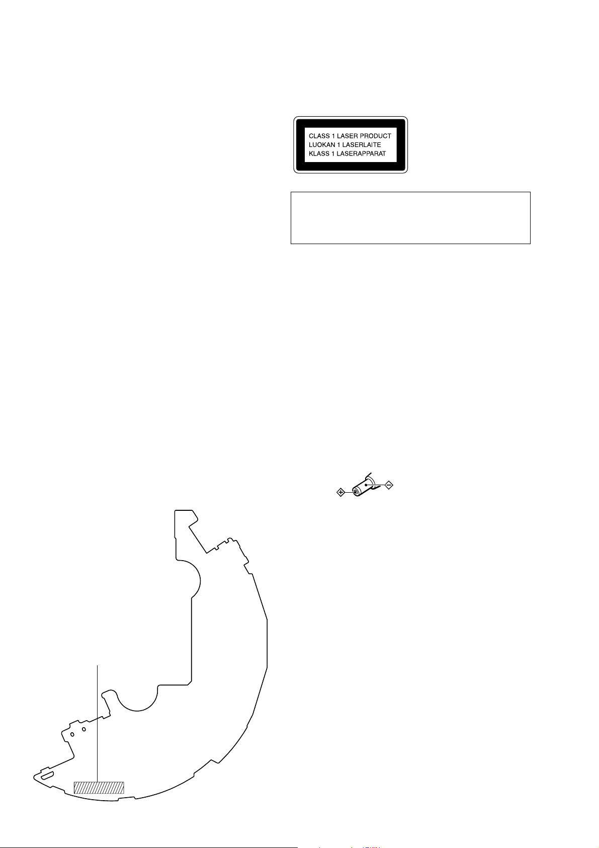
This appliance is classified as a CLASS 1 LASER product.
The CLASS 1 LASER PRODUCT MARKING is located on
the rear exterior.
CAUTION
Use of controls or adjustments or performance of procedures
other than those specified herein may result in hazardous radiation exposure.
Flexible Circuit Board Repairing
• Keep the temperature of the soldering iron around 270 ˚C during repairing.
• Do not touch the soldering iron on the same conductor of the
circuit board (within 3 times).
• Be careful not to apply force on the conductor when soldering
or unsoldering.
Notes on chip component replacement
• Never reuse a disconnected chip component.
• Notice that the minus side of a tantalum capacitor may be dam-
aged by heat.
Discrimination of MAIN board
– MAIN Board (Component Side) –
1-678-954-11,
1-678-954-12
or
1-678-954-13
On AC power adaptor
• Use only the AC power adaptor supplied or
recommended in “Accessories (supplied/
optional).” Do not use any other AC power
adaptor. It may cause a malfunction.
Polarity of the plug
ATTENTION AU COMPOSANT AYANT RAPPORT
À LA SÉCURITÉ!
LES COMPOSANTS IDENTIFIÉS P AR UNE MARQUE 0
SUR LES DIAGRAMMES SCHÉMA TIQUES ET LA LISTE
DES PIÈCES SONT CRITIQUES POUR LA SÉCURITÉ
DE FONCTIONNEMENT. NE REMPLACER CES COMPOSANTS QUE PAR DES PIÈCES SONY DONT LES
NUMÉROS SONT DONNÉS DANS CE MANUEL OU
DANS LES SUPPLÉMENTS PUBLIÉS PAR SONY.
SAFETY-RELATED COMPONENT WARNING!!
COMPONENTS IDENTIFIED BY MARK 0 OR DOTTED
LINE WITH MARK 0 ON THE SCHEMATIC DIAGRAMS
AND IN THE PARTS LIST ARE CRITICAL TO SAFE
OPERATION. REPLACE THESE COMPONENTS WITH
SONY PARTS WHOSE PART NUMBERS APPEAR AS
SHOWN IN THIS MANU AL OR IN SUPPLEMENTS PUBLISHED BY SONY.
2
SECTION 1
SERVICING NOTES
D-E888/E999/EJ825/EJ925
NOTES ON HANDLING THE OPTICAL PICK-UP BLOCK OR BASE UNIT
The laser diode in the optical pick-up block may suffer electrostatic breakdown because of the potential difference generated by
the charged electrostatic load, etc. on clothing and the human body .
During repair, pay attention to electrostatic breakdown and also
use the procedure in the printed matter which is included in the
repair parts.
The flexible board is easily damaged and should be handled with
care.
NOTES ON LASER DIODE EMISSION CHECK
The laser beam on this model is concentrated so as to be focused
on the disc reflective surface by the objective lens in the optical
pick-up block. Therefore, when checking the laser diode emission, observe from more than 30 cm away from the objecti ve lens.
BEFORE REPLACING THE OPTICAL PICK-UP BLOCK
Please be sure to check thoroughly the parameters as par the “Optical Pick-Up Block Checking Procedures” (Part No.: 9-960-027-
11) issued separately before replacing the optical pick-up block.
Note and specifications required to check are given below.
• FOK output: IC601 eg pin
When checking FOK, remove the lead wire to disc motor.
• RF signal P-to-P value: 0.4 to 0.6 Vp-p
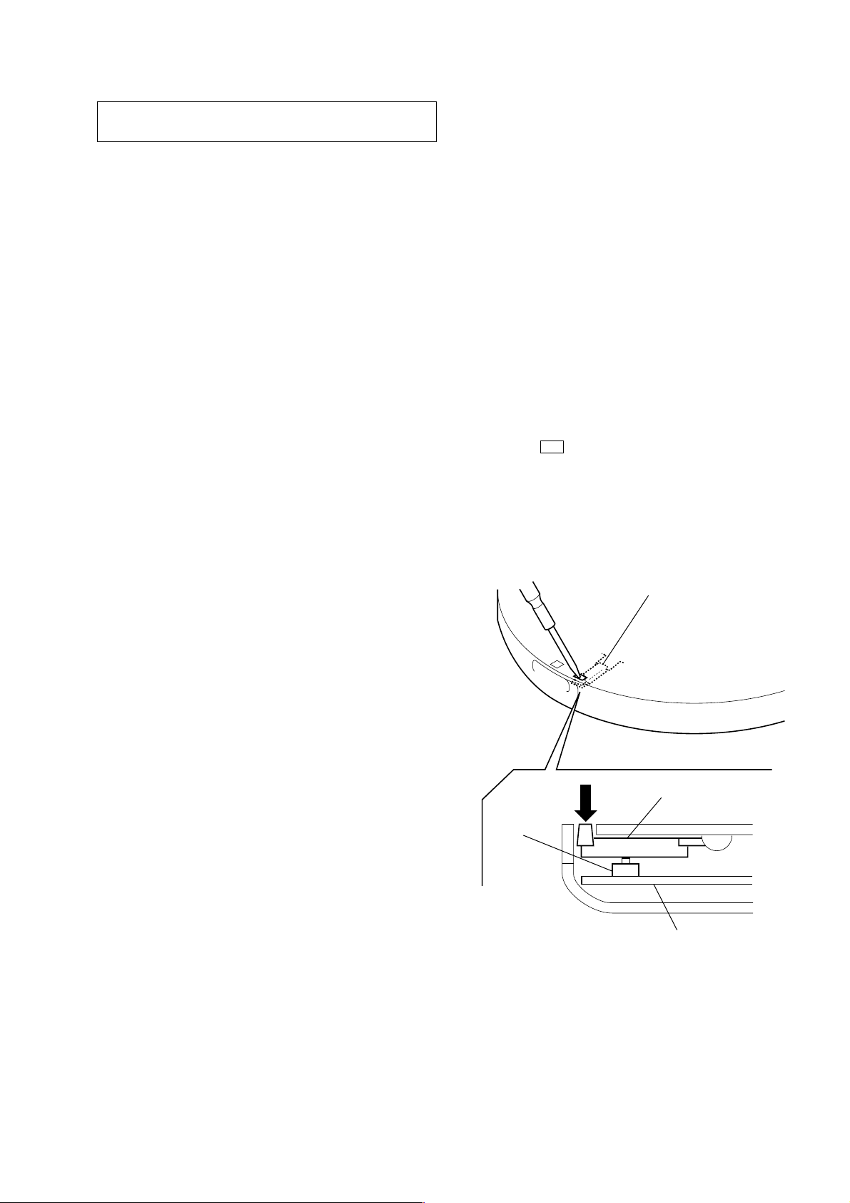
LASER DIODE AND FOCUS SEARCH OPERATION
CHECK
During normal operation of the equipment, emission of the laser
diode is prohibited unless the upper lid is closed while turning ON
the S801. (push switch type)
The following checking method for the laser diode is operable.
• Method:
Emission of the laser diode is visually checked.
1. Open the upper lid.
2. With a disc not set, turn on the S801 with a screwdri ver having
a thin tip as shown in Fig.1.
3. Press the
4. Observing the objective lens, check that the laser diode emits
light.
When the laser diode does not emit light, automatic power
control circuit or optical pickup is faulty.
In this operation, the objective lens will move up and down 4
times along with inward motion for the focus search.
u button.
S801
lever, detection
lever, detection
MAIN board
Fig. 1 Method to push the S801
3
D-E888/E999/EJ825/EJ925
SERVICE MODE
In the Service mode, this set can check the following.
1. Service Mode Setting Method
To set the Service mode, perform as follows.
1) Make sure that the Power is not turned on.
2) Check for the following states:
Open/close detection switch (S801)...... OFF
Solder bridge at TAP802 (OPEN) ......... OPEN
[ALVS] switch (S803) ........................... NORM
[HOLD] switch (S804) .......................... OFF
[G-PRO] switch (S805)......................... 1
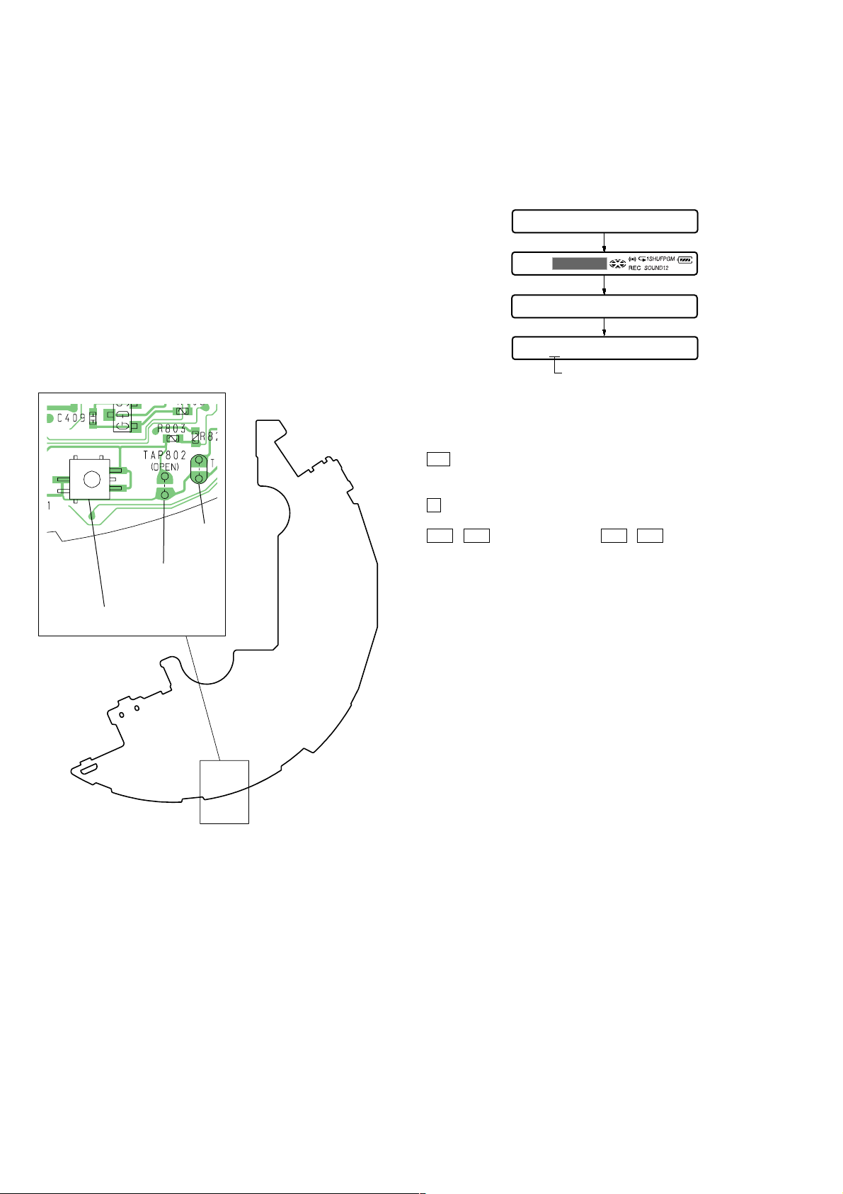
3) Short the solder bridge at the TAP801 (TEST) on the Main
board (see Fig. 2).
4) Turn the Power on.
– MAIN Board (Component side) –
TAP801
(TEST)
TAP802
(OPEN)
S801
(OPEN/CLOSE/ DETECT)
2. Operation in Service Mode
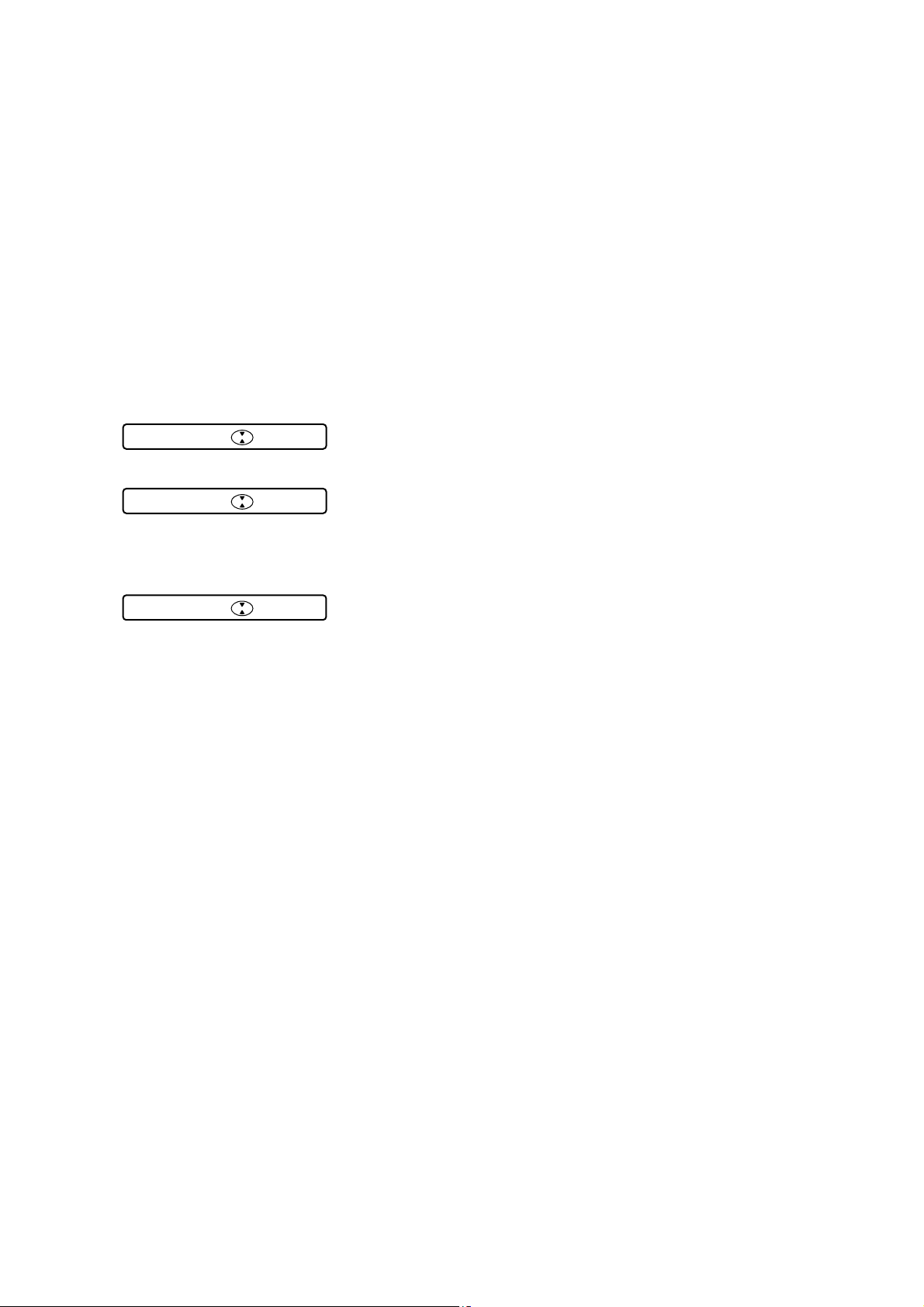
When the Service mode is set, the LCD on the remote commander
displays the following.
Remote commander LCD display
Microcomputer
version display
All lit
All off
Microcomputer
version display
3.Operation of Buttons and Knobs in Service Mode
The following operation can be checked by operating the buttons
and knobs on the set and remote commander.
u button on the set
•
Focus ON
Tracking/Thread servo OFF
• x button on the set and remote commander
All servos (Focus/Tracking/Thread) OFF
• > / . buttons on the set and > / . knobs on remote
commander
Optical pickup movement (outward or inward)
Tracking/Thread servo OFF
• [PLAYMODE] button on remote commander (CLV speed be-
comes 1 to 4 times each time the button is pressed)
Tracking/Thread servo ON
• [PRT/ENT] buttons on remote commander
Tracking gain up mode
• [VOL+] / [VOL--] buttons on the set and [VOL+] / [VOL--]
knobs on remote commander
2-step volume setting
• [SOUND] button on remote commander
Servo auto adjustment (In play mode, press this button before
pressing the [PLAYMODE] button on remote commander)
VB025
888
%B025
Uncertain
BASS12
4.Service Mode Releasing Method
To release the Service mode, perform as follows.
1) Turn the Power off.
2) Open the solder bridge at the TAP801 (TEST) on the Main
board.
Fig. 2
Note: Remove the solder completely.
4
5.Error Rate Check Display
The C1 Error Rate Check Display mode becomes active if the following operation is performed during the operation in the normal
mode.
1) Make sure that the Power is not turned on.
2) Fix the open/close detection switch (S801) on the Main board
with a tape so that the switch is turned on.
Or, short the solder bridge at the TAP802 (OPEN) on the Main
board (see Fig. 2 on page 4).
3) Turn the Power on, then set the CD to activate the Play mode.
4) Short the solder bridge at the TAP801 (TEST) on the Main
board (see Fig. 2 on page 4).
5) Press the [DISPLAY] button on remote commander, and the
C1 Error Rate Check Display mode becomes active, and the
remote commander LCD displays the following.
OK is displayed when the error rate is 0 to 99/7350, or NG is
displayed when over 100/7350.
Remote commander LCD display (OK display)
00 00
---
Remote commander LCD display (NG display)
D-E888/E999/EJ825/EJ925
11 11
---
The remote commander LCD displays the following when no
data is read such as in the skip mode.
Remote commander LCD display
---:--
---
Note: Press again the [DISPLAY] button on remote com-
mander, and the remote commander LCD displays the
time counted down from total time of CD.
Press once more the [DISPLAY] button on remote commander, and the remote commander LCD returns to
the display of the music being played at present.
6) Turn the Power off.
7) Open the solder bridges at the TAP801 (TEST) and TAP802
(OPEN) on the Main board.
Note: Remove the solder completely.
5
D-E888/E999/EJ825/EJ925
SECTION 2
GENERAL
This section is extracted from
instruction manual.
Getting started
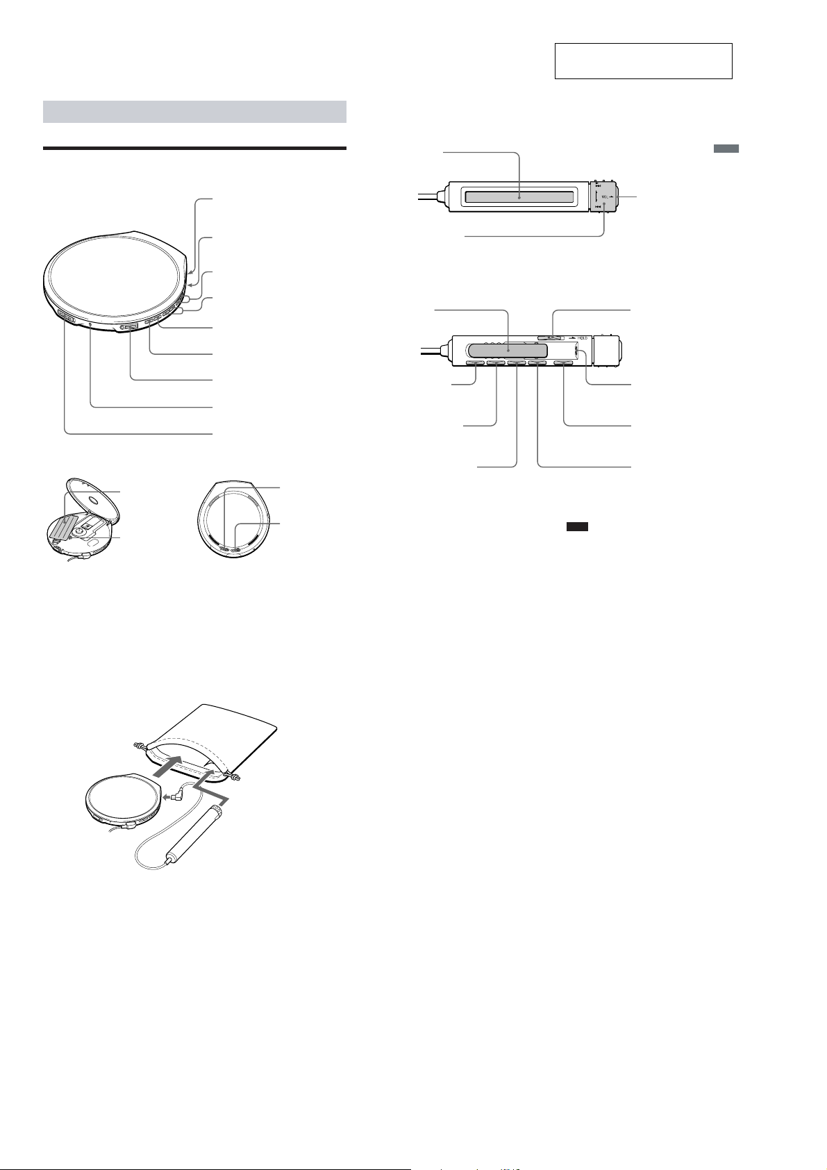
Locating the controls
For details, see pages in parentheses.
CD player (front)
CD player (inside)
q; Battery
compartment
(pages 19)
qa G-PRO (G-
PROTECTION)
switch
4
(page 13)
1 EXT BATT (external battery)/
DC IN 4.5 V (external power
input) jack (pages 7, 19, 21)
2 LINE OUT (OPTICAL) jack
(page 17)
3 VOL (volume) +/– buttons
(page 8)
4 ./> (AMS/search)
buttons
(pages 8, 11, 12)
5 u (play/pause) button
(page 8)
6 x (stop) /CHG (charge) button
(pages 8, 16, 19)
7 i (headphones) jack
(page 7)
8 CHG (charge)/HOLD lamp
(pages 15, 19)
9 OPEN switch
(page 7)
CD player (rear)
qs AVLS switch
(page 15)
qd HOLD switch
(page 15)
Remote control
qf Display
(pages 9, 11 - 15)
qg Rotary control
N/>: play, AMS/search (pages 8, 11, 12)
.: AMS/search (pages 8, 11, 12)
VOL +/–: Pull the control in the direction of the
arrow, and then turn it toward + or –. (page 8)
qj Clip
qk DISPLAY
button
(pages 13, 14)
ql PLAY MODE
button
(pages 10 - 12, 16)
w; RPT (repeat)/ENT
(enter) button
(pages 10 - 12)
qh x (stop) button
(pages 8, 16)
wa HOLD switch
(page 15)
ws i (headphones) jack
(page 7)
wd X (pause) button
(page 8)
wf SOUND button
(page 14)
Note
Use only the supplied remote control. You cannot
operate this CD player with the remote control
supplied with other CD players.
Getting started
5
Using the carrying case
You can carry your player and its battery case together using the supplied carrying case. Insert
them into the proper places in the case as illustrated below
.
6
6
D-E888/E999/EJ825/EJ925
n
SECTION 3
DISASSEMBLY
• This set can be disassembled in the order shown below.
Set Cabinet (Upper) Section “Cabinet (Upper) Sub Assy”, “Lid Sub Assy, Upper” (E888/EJ825 Model)
“Cabinet (Upper) Sub Assy”, “Lid Sub Assy, Upper” (E999/EJ925 Model)
“Main Board”, “Optical Pick-Up Section (CDM-3021EBG)”
Setting The Battery Terminal Board (Relay) Lead Wire And
Motor Lead Wires
Note: Follow the disassembly procedure in the numerical order given.
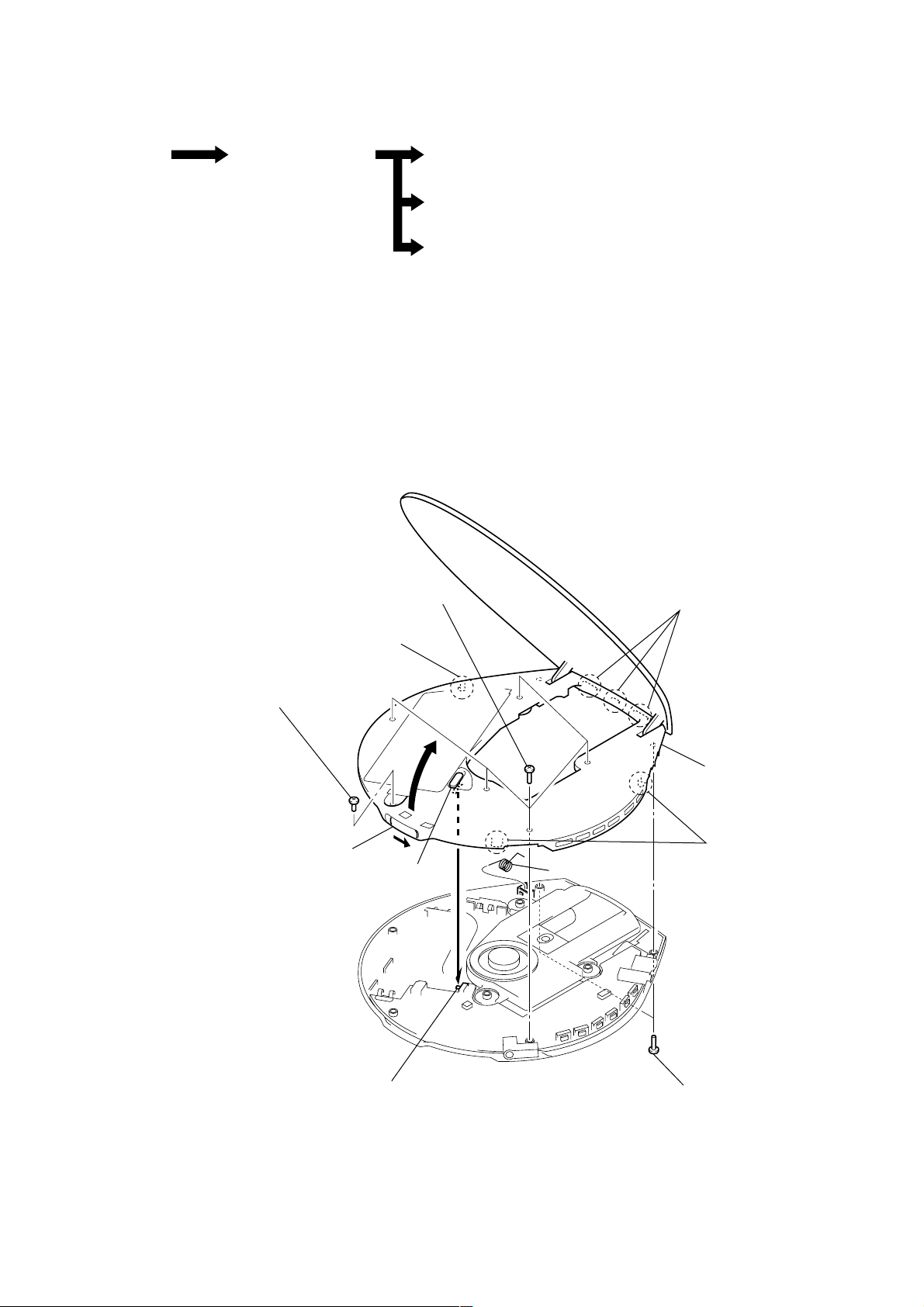
CABINET (UPPER) SECTION
4
3
screw (B2)
2
Open the upper lid sub assy.
Note on installation cabinet (upper) section:
When installing cabinet (upper) section,
adjust the S805 and knob (AVLS).
five screws (B2)
5
claw
knob (AVLS)
7
spring (open)
5
three claws
6
cabinet (upper) sectio
5
two claws
S805
1
two screws (B2)
7
D-E888/E999/EJ825/EJ925
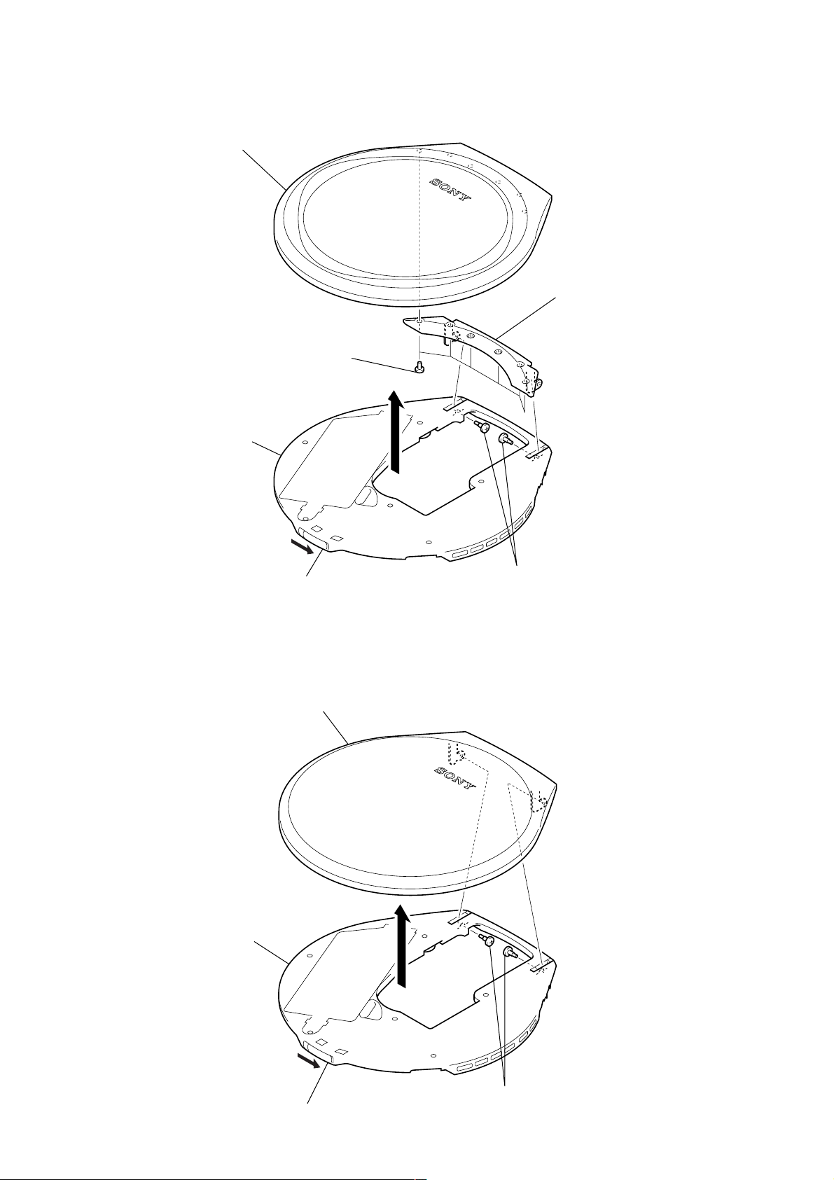
“CABINET (UPPER) SUB ASSY”, “LID SUB ASSY, UPPER” (E888/EJ825 MODEL)
7
lid sub assy, upper
6
plate, fulcrum
5
six tapping screws
×
2.5)
(1.7
4
cabinet (upper) sub assy
3
1
2
Open the upper lid sub assy.
two screws
“CABINET (UPPER) SUB ASSY”, “LID SUB ASSY, UPPER” (E999/EJ925 MODEL)
5
lid sub assy, upper
4
cabinet (upper) sub assy
3
1
two screws
2
Open the upper lid sub assy.
8
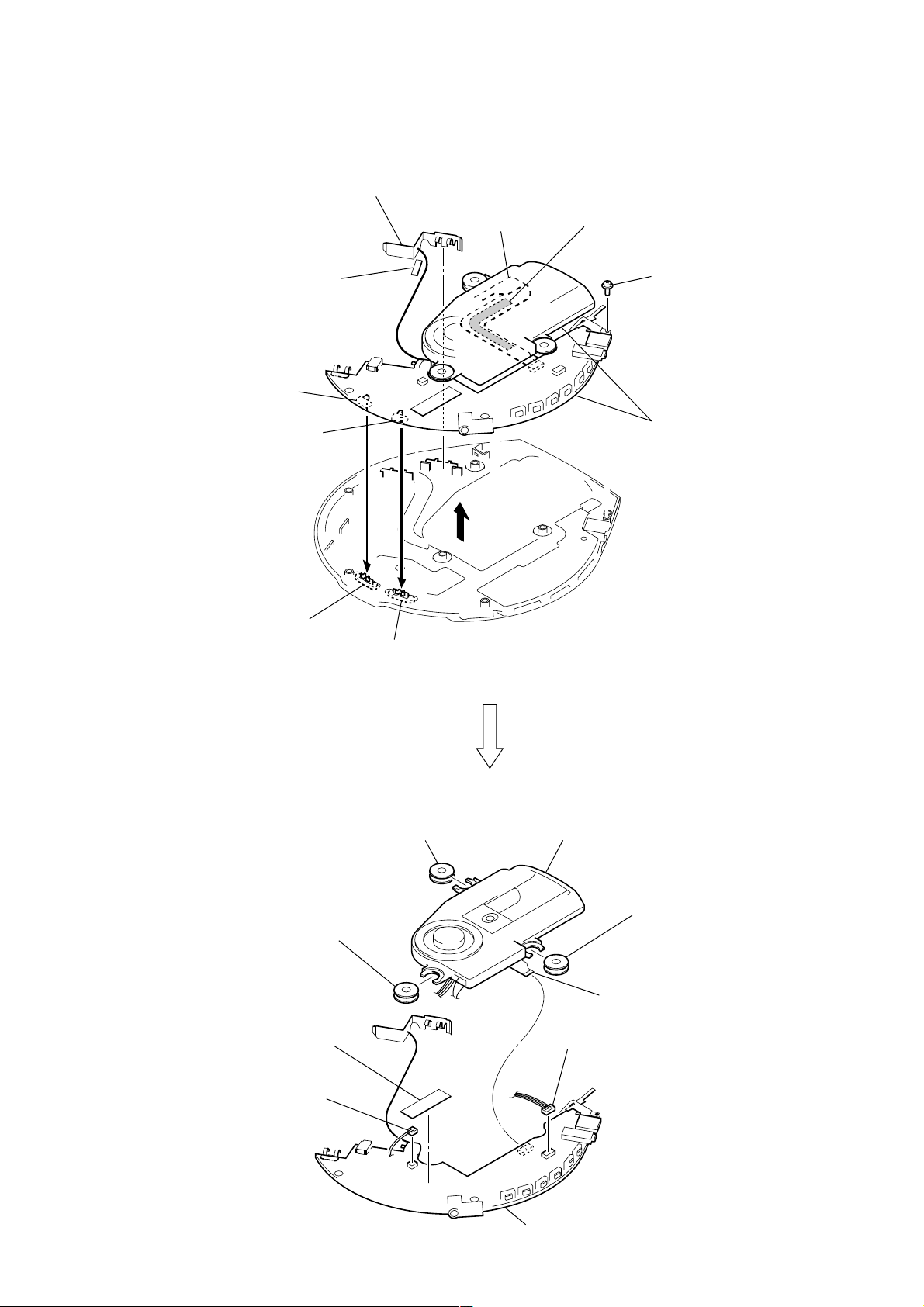
“MAIN BOARD”, “OPTICAL PICK-UP SECTION (CDM-3021EBG)”
d
Note: Do not apply an excessive force
3
terminal board (relay), battery
2
saranet cushion
S804
S803
Note on installation MAIN board:
When installing MAIN board,
adjust the S803, S804 and
knob (AV, HOLD).
optical pick-up
flexible board
4
D-E888/E999/EJ825/EJ925
when removing an adhesive sheet (MD)
from the optical pick-up flexible board.
Holding up the optical pick up section
a little, remove the adhesive sheet (MD).
1
tapping screw (B) (1.4 × 3)
5
Hold up both the optical pick-up
section and the main board at
the same time.
Note: Be careful to hold them up
because the optical pick-up
flexible board is still connected
to the main board.
knob (HOLD)
q;
spacer (MD)
6
cushion
knob (AV)
q;
spacer (MD)
qa
optical pick-up section
(CDM-3021EBG)
q;
spacer (MD)
8
optical pick-up flexible boar
(CN501)
7
connector
(CN502)
7
connector
(CN503)
9
MAIN board
9
D-E888/E999/EJ825/EJ925
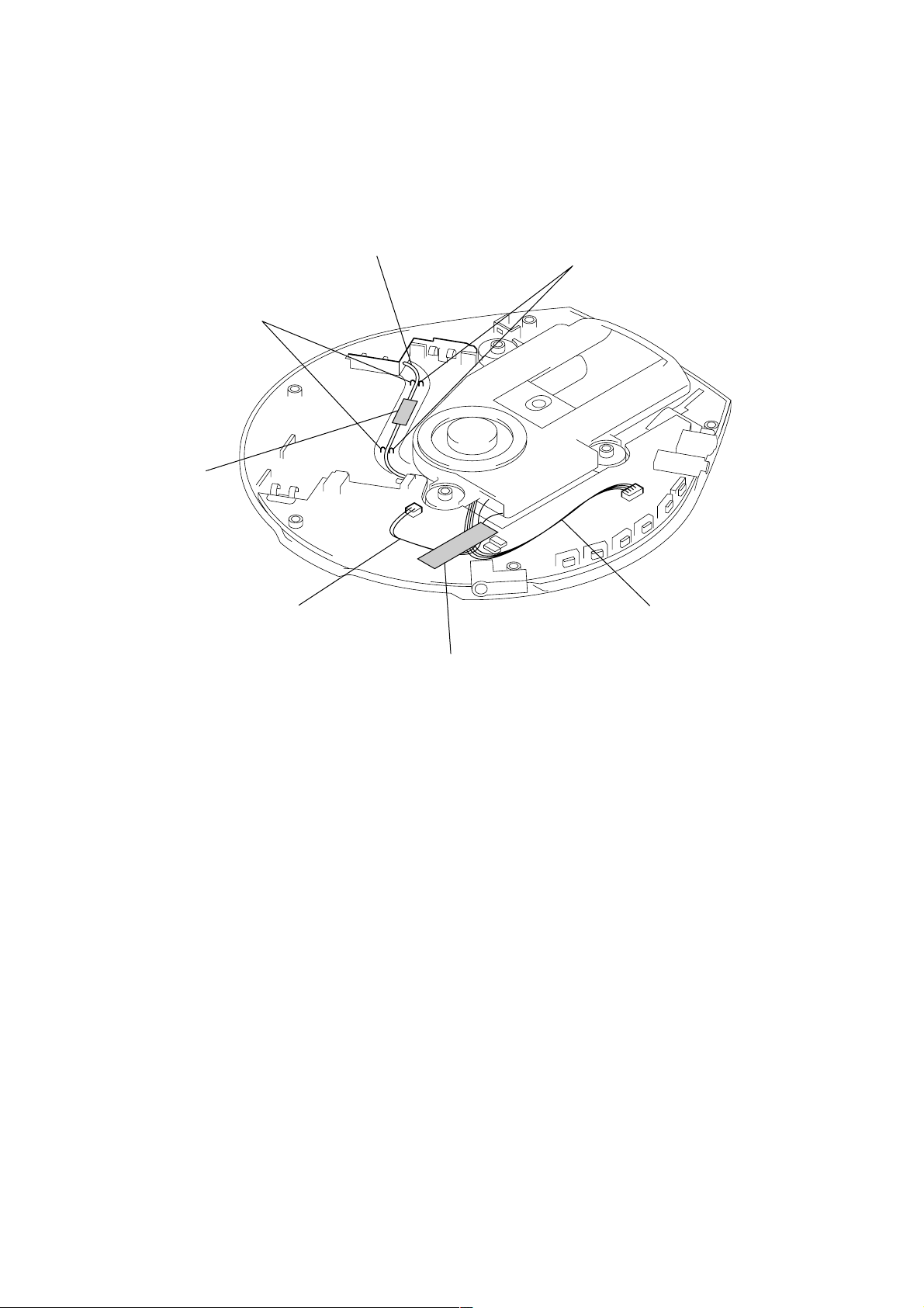
s
SETTING THE BATTERY TERMINAL BOARD (RELAY) LEAD WIRE AND MOTOR LEAD WIRES
Note: Install the battery terminal board (relay) lead wire,
aligning with four bosses.
Fix them to the position shown in figure using
saranet cushion.
two bosses
saranet cushion
battery terminal board (relay)
lead wire
two bosses
motor lead wires
motor lead wire
cushion
Note: In routing the motor lead wires,
fix them to the position shown in
figure using cushion.
10
 Loading...