

Sony DE-85 Service manual
D-E808/E885
SERVICE MANUAL
Ver 1.1 1999. 02
SPECIFICATIONS
US Model
Canadian Model
AEP Model
UK Model
E Model
Australian Model
Chinese Model
D-E885
Tourist Model
D-E808
Model Name Using Similar Mechanism D-E800/E805
CD Mechanism Type CDM-2911EBA
Optical Pick-Up Name DAX-11E
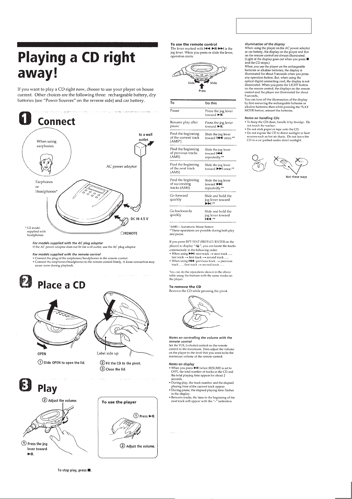
CD player section
System
Compact disc digital audio system
Laser diode properties
Material: GaAlAs
Wavelength: λ = 780 nm
Emission duration: Continuous
Laser output: Less than 44.6 µW (This output
is the value measured at a distance of 200
mm from the objective lens surface on the
optical pick-up block with 7 mm aperture.)
Error correction
Sony Super Strategy Cross Interleave Reed
Solomon Code
D-A conversion
1-bit quartz time-axis control
Frequency response
20 - 20,000 Hz
307)
Output (at 4.5 V input level)
Headphones (stereo minijack)
15 mW + 15 mW at 16 ohms
Line output (stereo minijack)
Output level 0.7 V rms at 47 kilohms
Recommended load impedance over 10
kilohms
Optical digital output (optical output
connector)
Output level: –21 to –15 dBm
Wavelength: 630 – 690 nm at peak level
+1
dB (measured by EIAJ CP-
–2
General
Power requirements
For the area code of the model you purchased,
check the upper left side of the bar code on the
package.
• Two Sony NH-DM2AA rechargeable
batteries: 2.4 V DC
Two Sony NC-DMAA rechargeable
batteries: 2.4 V DC
• Two LR6 (size AA) batteries: 3 V DC
• AC power adaptor (DC IN 4.5 V jack):
US/Canadian model: 120 V, 60 Hz
AEP/E13 model: 220 – 230 V, 50/60 Hz
UK model: 230 – 240 V, 50Hz
Australian model: 240 V, 50 Hz
Tourist/E33 model: 100 – 240 V, 50/60 Hz
Hong Kong model: 220 V, 50/60 Hz
Chinese model: 220 V, 50 Hz
• Sony DCC-E245 car battery cord for use on
car battery: 4.5 V DC
Dimensions (w/h/d) (without projecting
parts and controls)
Approx. 131.8 × 24.2 × 142.0 mm
(5 1/4 × 31/32 × 5 5/8 in.)
Mass (without rechargeable batteries)
Approx. 210 g (7.4 oz)
Operating temperature
5 ˚C – 35 ˚C (41 ˚F – 95 ˚F)
Supplied accessories
For the area code of the model you purchased,
check the upper left side of the bar code on the
package.
AC power adaptor (1)
Headphones with remote control (1)*
Earphones with remote control (1)*
Rechargeable batteries (2)
AC plug adaptor (1)*
Battery carrying case (1)
Carrying case (1)
*1Supplied with US model
*2Not supplied with US model
*3Supplied with Tourist, E33 and E13 models
Design and specifications are subject to change
without notice.
• Abbreviation
E13: 220 – 230 V AC area in E model
E33: 100 – 240 V AC area in E model
3
1
2
MICROFILM
COMPACT DISC COMPACT PLAYER
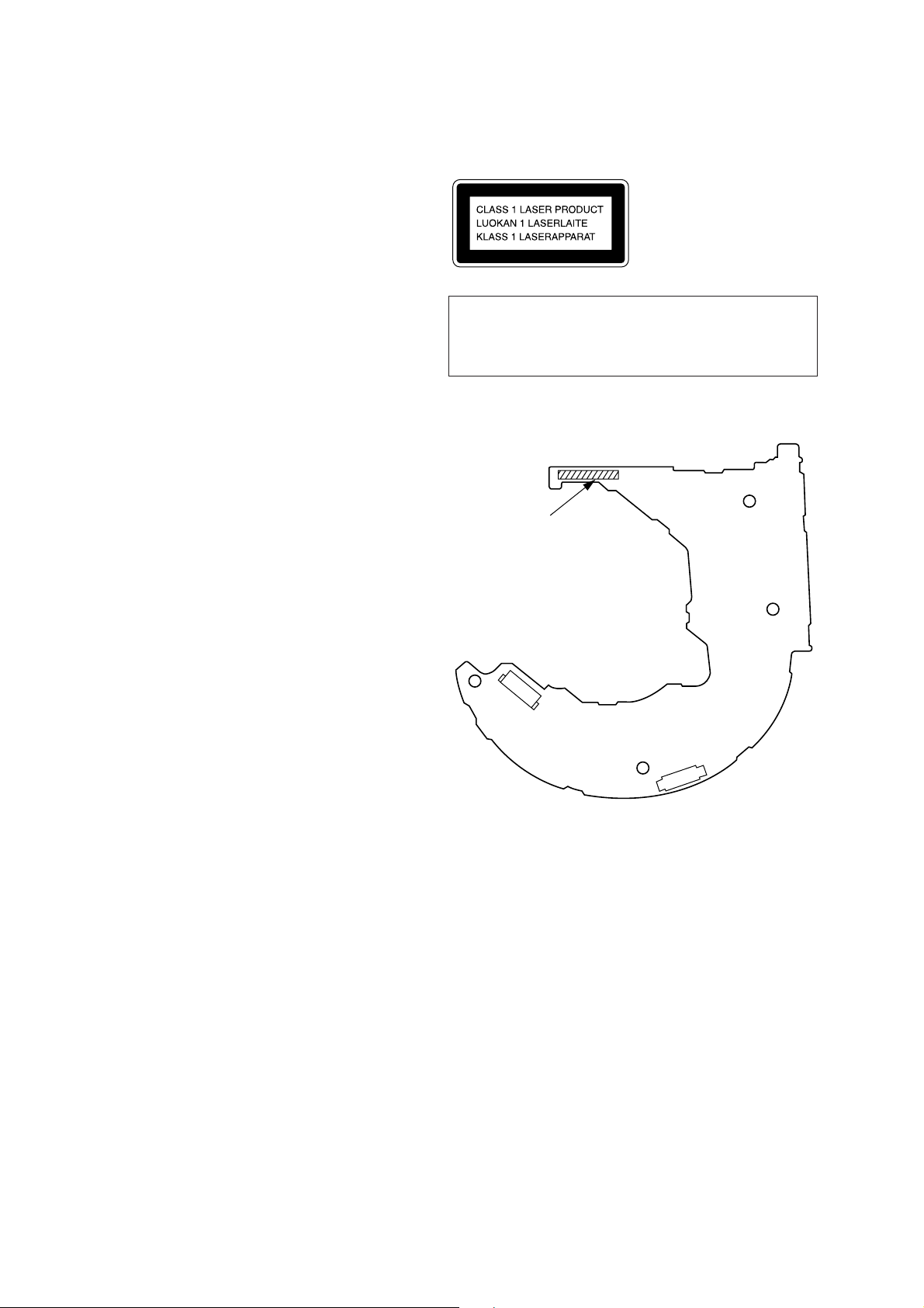
TABLE OF CONTENTS
1. SERVICING NOTES ............................................... 3
2. GENERAL ................................................................... 4
3. DISASSEMBLY ......................................................... 8
4. SERVICE MODE...................................................... 9
This appliance is classified as a CLASS 1 LASER product.
The CLASS 1 LASER PRODUCT MARKING is located on
the rear exterior.
5. ELECTRICAL ADJUSTMENTS......................... 10
6. DIAGRAMS
6-1. Block Diagram – MAIN Section – ................................. 15
6-2. Block Diagram – POWER SUPPLY Section – .............. 19
6-3. IC Pin Function Description ........................................... 21
6-4. Printed Wiring Boards (Suffix-11) ................................. 24
6-5. Schematic Diagram (Suffix-11)...................................... 27
6-6. Schematic Diagram (Suffix-12)...................................... 31
6-7. Printed Wiring Board (Suffix-12) ................................... 35
7. EXPLODED VIEWS ................................................ 43
8. ELECTRICAL PARTS LIST ............................... 46
CAUTION
Use of controls or adjustments or performance of procedures
other than those specified herein may result in hazardous radiation exposure.
Discrimination of MAIN board
– MAIN BOARD (Side A) –
1-671-585-11
or
1-671-585-12
Flexible Circuit Board Repairing
• Keep the temperature of the soldering iron around 270 ˚C during repairing.
• Do not touch the soldering iron on the same conductor of the
circuit board (within 3 times).
• Be careful not to apply force on the conductor when soldering
or unsoldering.
Notes on chip component replacement
• Never reuse a disconnected chip component.
• Notice that the minus side of a tantalum capacitor may be damaged by heat.
SAFETY-RELATED COMPONENT WARNING!!
COMPONENTS IDENTIFIED BY MARK ! OR DOTTED
LINE WITH MARK ! ON THE SCHEMATIC DIAGRAMS
AND IN THE PARTS LIST ARE CRITICAL TO SAFE
OPERATION. REPLACE THESE COMPONENTS WITH
SONY PARTS WHOSE PART NUMBERS APPEAR AS
SHOWN IN THIS MANUAL OR IN SUPPLEMENTS PUBLISHED BY SONY.
ATTENTION AU COMPOSANT AYANT RAPPORT
À LA SÉCURITÉ!
LES COMPOSANTS IDENTIFIÉS P AR UNE MARQUE !
SUR LES DIAGRAMMES SCHÉMATIQUES ET LA LISTE
DES PIÈCES SONT CRITIQUES POUR LA SÉCURITÉ
DE FONCTIONNEMENT. NE REMPLACER CES COMPOSANTS QUE PAR DES PIÈCES SONY DONT LES
NUMÉROS SONT DONNÉS DANS CE MANUEL OU
DANS LES SUPPLÉMENTS PUBLIÉS PAR SONY.
– 2 –
SECTION 1
SERVICING NOTES
NOTES ON HANDLING THE OPTICAL PICK-UP
BLOCK OR BASE UNIT
The laser diode in the optical pick-up block may suffer electrostatic breakdown because of the potential difference generated by
the charged electrostatic load, etc. on clothing and the human body .
During repair, pay attention to electrostatic breakdown and also
use the procedure in the printed matter which is included in the
repair parts.
The flexible board is easily damaged and should be handled with
care.
Befor Replacing the Optical Pick-Up Block
Please be sure to check thoroughly the parameters as par the “Optical Pick-Up Block Checking Procedures” (Part No.: 9-960-027-
11) issued separately before replacing the optical pick-up block.
Note and specifications required to check are given below.
• FOK output: IC501 !™ pin
When checking FOK, remove the lead wire to disc motor.
• S curve P-to-P value: 0.6 to 1.8 Vp-p IC501 #¡ pin
When checking S curve P-to-P value, remove the lead wire to
disc motor.
• RF signal P-to-P value: 0.8 to 1.2 Vp-p
• Traverse signal P-to-P value: 1.2 Vp-p
• The repairing grating holder is impossible.
Precautions for Checking Emission of Laser Diode
Laser light of the equipment is focused by the object lens in the
optical pick-up so that the light focuses on the reflection surface
of the disc. Therefore, be sure to keep your eyes more then 30 cm
apart from the object lens when you check the emission of laser
diode.
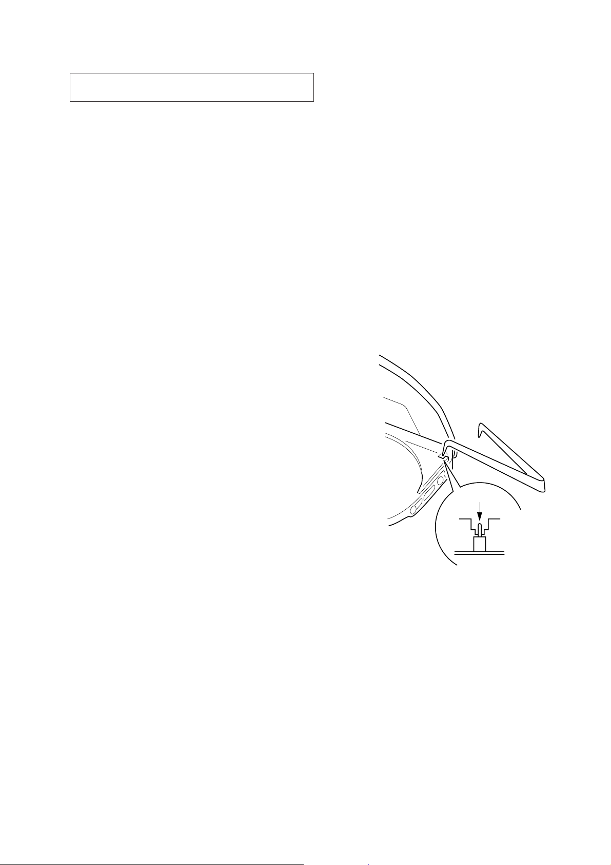
Laser Diode Checking Methods
During normal operation of the equipment, emission of the laser
diode is prohibited unless the upper panel is closed while turning
ON the S801. (push switch type)
The following two checking methods for the laser diode are operable.
• Method (In the service mode or normal operation):
Emission of the laser diode is visually checked.
1. Open the upper lid.
2. Push the S801 as shown in Fig. 1.
3. Press the ^ key.
4. Check the object lens for confirming normal emission of the
laser diode. If not emitting, there is a trouble in the automatic
power control circuit or the optical pick-up.
During normal operation, the laser diode is turned ON about
2.5 seconds for focus searching.
S801
Fig. 1 Method to push the S801
– 3 –
SECTION 2
GENERAL
This section is extracted from
instruction manual.
– 4 –
– 5 –
– 6 –
– 7 –
SECTION 3
DISASSEMBLY
Note: Follow the disassembly procedure in the numerical order given.
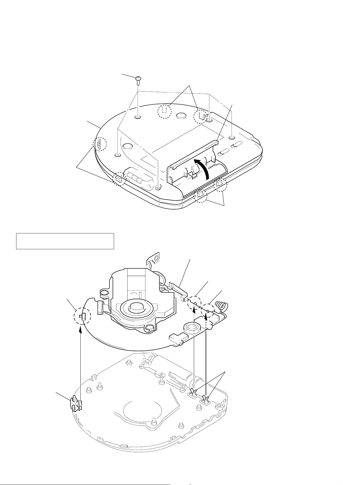
CABINET (LOWER)
1
five screws
(2
×
8)
5
cabinet (lower)
4
two claws
4
two claws
2
Open the battery case lid.
INSTALLATION MAIN BOARD
On installation MAIN board adjust the
S301, 803, 804, and knob (H-R, A VLS).
S804
3
two claws
Note:Take care not to allow the rechargeable
battery detection plate to ride on the mold
of the bottom plate.
S301
S803
knob (AVLS)
knob (H-R)
– 8 –
SECTION 4
SERVICE MODE
Service Mode (Service program)
The equipment is provided with a service program built in the
microcomputer, like conventional models.
Service program operation methods are described in the following.
PLAY MODE
HOLD
c
Be sure to turn OFF
the HOLD switch
(If ON, all the LCD
indication and
LED are lightup)
=
(FR)
The optical pick-up
is moved inwardly
+
The optical pick-up
is moved outwardly
(FF)
Tracking servo and sled
servo are turned ON
REPEAT/ENTER
Tracking gain-up mode
while pressing
^
(PLAY/PAUSE)
Focus is tuned ON to
effect draw-in mode
p
(STOP)
[All servos are turned OFF]
4. By pressing the ^ key, focus is turned ON from focus search-
ing while entering CLV-S. (draw-in mode)
Without disc, focus searching is repeated continuously.
5. By pressing the PLAY MODE key, tracking servo, sled servo
and CLV-A (servo in PLAY) are turned ON.
6. When step 4 and 5 are performed, playing begins. No muting
is ON in the service mode.
7. By pressing the p key, all servos (focus, tracking and sled)
are turned OFF. However , the disc motor re volv es for a w hile
by inertia.
• Step 3 (Resetting of service mode)
1. Be sure to disconnect the external power supply and remove
the solder bridge at the TEST terminals connected before in
setting.
2. The set thus becomes available for normal operation.
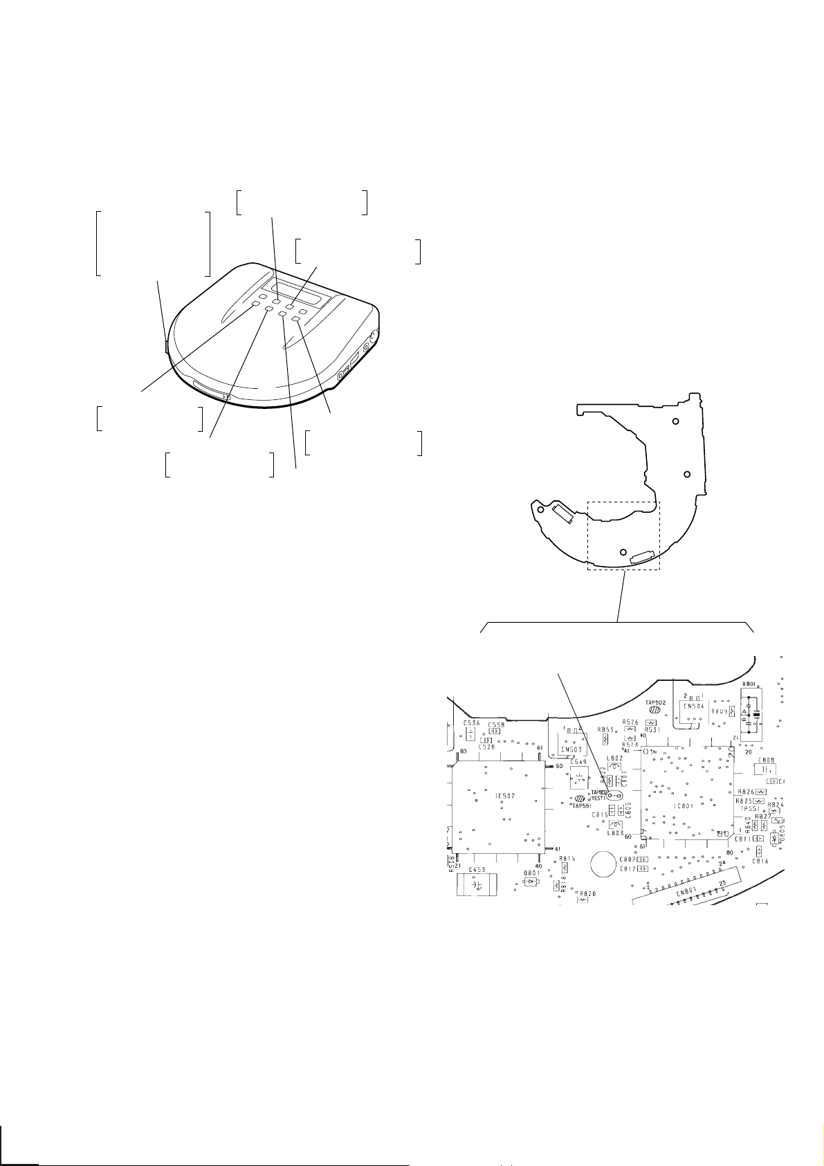
– MAIN BOARD (Side A) –
Descriptions in [ ] indicate major operations in the service
mode. For more informatrion, see Step 2.
Fig. 1 Layout of each key
• Step 1 (Service mode setting methods)
1. Turn OFF the HOLD switch with external power supply disconnected. (power is not applied to the set)
2. Solder across the TEST terminals (TAP802). (pin %¢, IC801
(ESPSL/TEST) is grounded)
3. Connect an external power supply.
Thus, the set is switched to the service mode.
• Step 2 (Operation in the service mode)
1. Once the service mode is ef fected, the LCD displays 5 indications each of which is repeatedly displayed.
However , the follo wing operations can be activated e ven if LCD
indication is effected.
2. By pressing the + or = ke y, the optical pick-up is movable inwardly or outwardly . Howe ver, if this is acti vated, tracking servo and sled servo are turned OFF, so it can be turned
ON by pressing the PLAY MODE key if required.
3. By pressing the REPEAT/ENTER key, the tracking gain-up
mode becomes active.
TAP802
(TEST)
– 9 –
Fig. 2 Location of Test terminal
SECTION 5
ELECTRICAL ADJUSTMENTS
Precautions for Adjustment
1. Before beginning adjustment, set the equipment to service
mode.
After the completion of adjustment, be sure to reset the service mode.
For more information, see “Service Mode (service program) ”
on page 9.
2. Perform adjustments in the order given.
3. Use YEDS-18 disc (P art No.: 3-702-101-01) unless otherwise
indicated.
4. Power supply voltage requirement: DC2.5 V in battery terminal
VOLUME knob : Minimum
RESUME switch : OFF
ESP switch : OFF
AVLS switch : NORMAL
HOLD switch : OFF
Before Beginning Adjustment
Set the equipment to service mode (See page 9) and check the
following. If there is an error, repair the equipment.
• Checking of the sled motor
1. Open the upper panel.
2. Press the + and = keys and check that the optical pickup can move smoothly without sluggishness or abnormal noise
in innermost periphery n outermost periphery n innermost
periphery
+ : The optical pick-up moves outwardly.
=: The optical pick-up moves inwardly.
• Checking of focus searching
1. Open the upper panel.
2. Press the ^ key. (Focus searching operation is activated
continuously)
3. Check the object lens of the optical pick-up for smooth up/
down motion without sluggishness or abnormal noise.
4. Press the p key.
Check that focus searching operation is deactivated. If not,
again press the p key slightly longer.
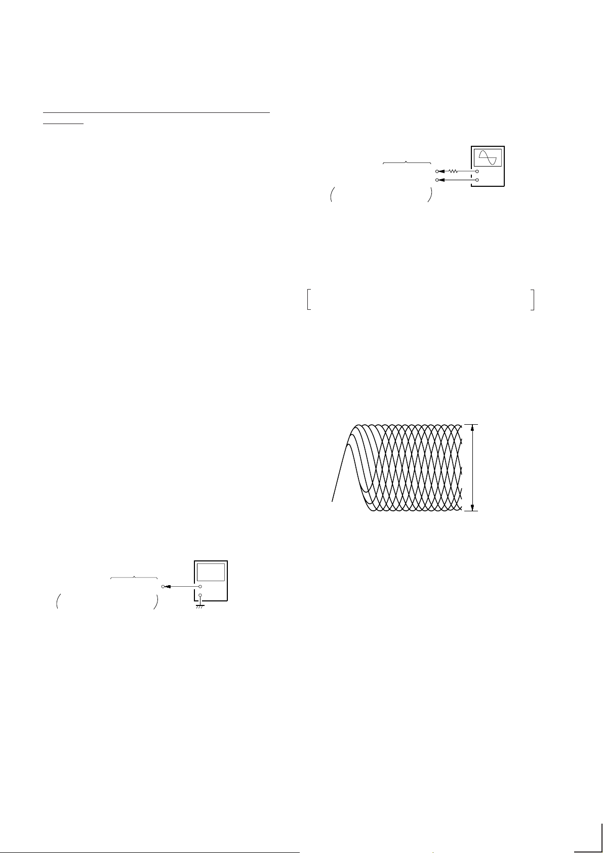
Focus bias Check
Condition:
• Hold the set in horizontal state.
Check Procedure:
oscilloscope
(AC range)
MAIN board
TP522 (RFO)
TP520 (VC)
SUFFIX-11: See page 12
SUFFIX-12: See page 13
2 k
Ω
+
–
1. Set the equipment to service mode stop state. (See page 9)
2. Connect the oscilloscope to the test point TP522 (RFO) on the
MAIN board.
3. Move the optical pick-up to the center by pressing the +
and = keys.
4. Put the disc. (YEDS-18)
5. Press the ^ key.
From focus searching, focus is turned ON while entering
CLV drawing-in mode. Tracking and sled are turned OFF.
6. Press the PLA Y MODE key . (Both tracking and sled are turned
ON)
7. Check the oscilloscope waveform is as shown below.
A good eye pattern means that the diamond shape (≈) in the
center of the waveform can be clearly distinguished.
RF Signal reference Waveform (Eye Pattern)
VOLT/DIV : 200 mV (With the 10:1 probe in use)
TIME/DIV : 500 ns
RF level
0.8 to 1.2 Vp-p
VCC Adjustment
Adjustment Procedure:
digital voltmeter
(DC range)
MAIN board
TP401 (VCC)
SUFFIX-11: See page 12
SUFFIX-12: See page 13
+
–
1. Set the equipment to service mode stop state. (See page 9)
2. Connect the digital voltmeter to TP401 (VCC) on the MAIN
board.
3. Adjust RV401 on the MAIN board so that the r eading on digital voltmeter goes 2.53 V.
Specifications: 2.5 V to 2.55 V
4. After the completion of adjustment, reset service mode. (See
page 9)
Adjustment Location:MAIN Board (SUFFIX-11: See page 12,
SUFFIX-12: See page 13)
To watch the eye pattern, set the oscilloscope to AC range and
increase the vertical sensitivity of the oscilloscope for easy watching.
8. Stop revolving of the disc motor by pressing the p key.
9. After the completion of adjustment, reset service mode. (See
page 9)
Checking Location: MAIN Board (SUFFIX-11: See page 12,
SUFFIX-12: See page 13)
– 10 –
 Loading...