

Sony DDM-2810CSU, DDM-2800CSU User Manual

Trinitron Data Display Monitor
DDM-2800CSU
DDM-2810CSU
Operating Instructions page 2
Before operating the unit, please read this manual thoroughly and retain
it for future reference.
3-858-566-11 (1)
Mode d’emploi page 6
Avant la mise en service de cet appareil, prière de lire attentivement ce
mode d’emploi que l’on conservera pour toute référence ultérieure.
Bedienungsanleitung Seite 10
Vor der Inbetriebnahme lesen Sie diese Anleitung sorgfältig durch und
bewahren Sie sie zum späteren Nachschlagen auf.
1996 Sony Corporation
English
Table of ContentsOwner’s Record
The model and serial numbers are located at the rear of the
unit. Record these numbers in the spaces provided below.
Refer to them whenever you call upon your Sony dealer
regarding this product.
Model No. Serial No.
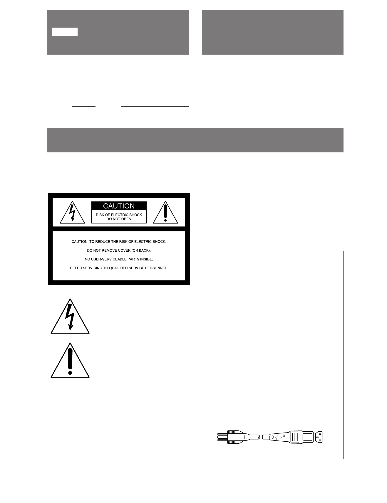
WARNING
To prevent fire or shock hazard, do not
expose the unit to rain or moisture.
WARNING........................................................................... 2
Features .............................................................................. 3
Precautions ......................................................................... 3
Location and Function of Controls ...................................... 4
Rear panel ..................................................................... 4
Specifications ...................................................................... 5
this equipment in a residential area is likely to cause harmful
interference in which case the user will be required to
correct the interference at his own expense.
You are cautioned that any changes or modifications not
expressly approved in this manual could void your authority
to operate this equipment.
The shielded interface cable recommended in this manual
must be used with this equipment in order to comply with
the limits for a digital device pursuant to Subpart B of Part
15 of FCC Rules.
This symbol is intended to alert the
user to the presence of uninsulated
"dangerous voltage" within the
product's enclosure that may be of
sufficient magnitude to constitute a
risk of electric shock to persons.
Thie symbol is intended to alert the
user to the presence of important
operating and maintenance
(servicing) instructions in the literature
accompanying the appliance.
For the customers in the USA
Warning-This equipment has been tested and found to
comply with the limits for a Class A digital device, pursuant
to Part 15 of the FCC Rules. These limits are designed to
provide reasonable protection against harmful interference
when the equipment is operated in a commercial
environment. This equipment generates, uses, and can
radiate radio frequency energy and, if not installed and used
in accordance with the instruction manual, may cause
harmful interference to radio communications. Operation of
NOTICE
This notice is applicable for USA/Canada only.
If shipped to USA/Canada, install only a UL LISTED/CSA
LABELED power supply cord meeting the following
specifications:
SPECIFICATIONS
Plug Type Nema-Plug 5-15p
Cord Type SVT or SJT, minimum 3 × 18,
AWG
Length Maximum 15 feet
Rating Minimum 7 A, 125 V
NOTICE
Cette notice s'applique aux Etats-Unis et au Canada
uniquement.
Si cet appareil est exporté aux Etats-Unis ou au Canada,
utiliser le cordon d'alimentation portant la mention UL
LISTED/CSA LABELED et remplissant les conditions
suivantes:
SPECIFICATIONS
Type de fiche Fiche Nema 5-15 broches
Cordon Type SVT ou SJT, minimum 3 × 18
AWG
Longueur Maximum 15 pieds
Tension Minimum 7 A, 125 V
2

Features Precautions
The DDM-2800CSU/2810CSU is a super-high-resolution
graphic display monitor which employs a raster scanning
method.
Super high density graphic display
The extremely high resolution of 2,048 dots (horizontal) ×
2,048 lines (vertical) per frame has been made possible
through the development of a 300 MHz band width video
amplifier.
20-inch by 20-inch useful screen size
The 32-inch Trinitron picture tube with an aspect ratio 1:1
presents a square picture.
Multi-layer optical coating
This minimizes reflections of ambient light.
This unit cannot be operated as a normal TV receiver/
monitor.
Power requirement
Each model is operated on AC 90 to 132 V and 180 to 264
V.Operate the unit on the correct power supply.
Safety
• Should any liquid or solid object fall into the cabinet,
unplug the unit and have it checked by qualified personnel
before operating it any further.
• Unplug the unit from the wall outlet if it is not to be used
for a long period of time.
Installation
• Allow adequate air circulation to prevent internal heat
build-up. Do not place the unit on surfaces (rugs, blankets,
etc.) or near materials (curtains) which might block the
ventilation holes.
• Do not install the unit in a location near heat sources such
as radiators or air ducts, or in a place subject to direct
sunlight, excessive dust, moisture, mechanical vibration,
or shock.
Transportation
• Do not throw away the carton and packing materials. They
make an ideal container in which to transport the unit.
When shipping the unit to another location, repack it as
illustrated on the carton.
• When carrying, handle it with care so as not to expose the
unit to mechanical shock, especially to the picture tube.
If you have any questions or problems about this unit,
consult your authorized Sony dealer.
3
Location and Function of Controls
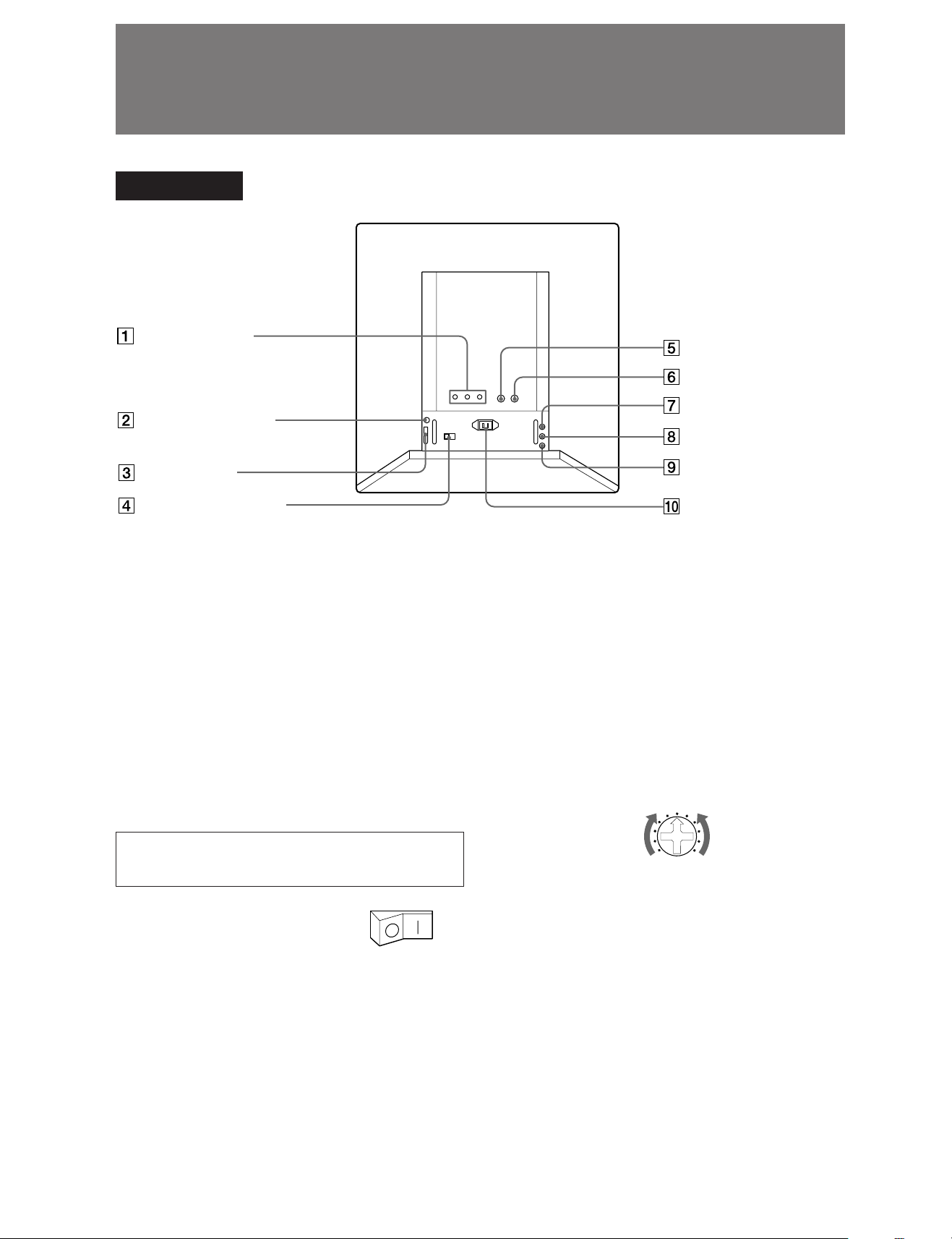
Rear panel
R/G/B VIDEO IN
connectors
LANDING SENSOR
connector
I/F connector
MAIN circuit breaker
1 R/G/B VIDEO IN (input) connectors (BNC type)
Inputs the R (red), G (green) and B (blue) signals. The
connectors are terminated at 50 ohms.
2 LANDING SENSOR connector (8 pin)∗
This connector is used when adjusting uneven color by
connecting the optional DDM-LS10 landing sensor.
3 I/F (interface) connector (D-sub 15 pin)∗
This connector is used when externally controlling
brightness, contrast, etc., and adjusting distortion,
convergence, color temperature, etc. by connecting the
optional DDM-RM10 controller.
∗ Adjustments 2 and 3 are performed by a service engineer.
Should the adjustment be required, please consult a Sony
representative.
4 MAIN circuit breaker
Set this circuit breaker to the I (on)
position when using this unit.
5 HD (horizontal drive) input connector (BNC
type)
Inputs horizontal drive pulses (HD). The connector is
terminated at 75 ohms.
HD input connector
VD input connector
POWER indicator
FAILURE indicator
ROTATION control
AC IN socket
7 POWER indicator (green)
Lights when the POWER switch on the front panel is
turned on.
8 FAILURE indicator (red)
Lights when the circuits inside the unit are not
functioning correctly. Should this lamp light, turn off the
MAIN circuit breaker and consult a Sony representative.
9 ROTATION CONTROL
Adjusts the picture rotation. Use a screwdriver etc. to
turn the control.
Rotate the picture
clockwise
Rotate the picture
counterclockwise
0 AC IN socket
Connect an AC power cord here.
Note
When connection to 1, 5 and 6, use a double-shielded coaxial
cable.
6 VD (vertical drive) input connector (BNC type)
Inputs vertical drive pulses (VD). The connecter is
terminated at 75 ohms.
4
Specifications
System 2,114 lines, 60 Hz non-interlaced, Raster
scanning system
(Horizontal display time 5.734 µs)
Picture tube Super fine-pitch Trinitron color tube
0.31 mm phosphor trio pitch
P22 phosphor
90 degree deflection
69% total optical transmission
Picture size 498 (w) × 498 (h) mm (19.6 × 19.6 inches)
Addressable pixels
2,048 dots (H) × 2,048 lines (V)
Video amplifier Band width; 60 Hz to 300 MHz ±3 dB
Pulse rise/fall time: 1.3 ns or less
Maximum brightness
More than 80 cd/m2 (at screen center)
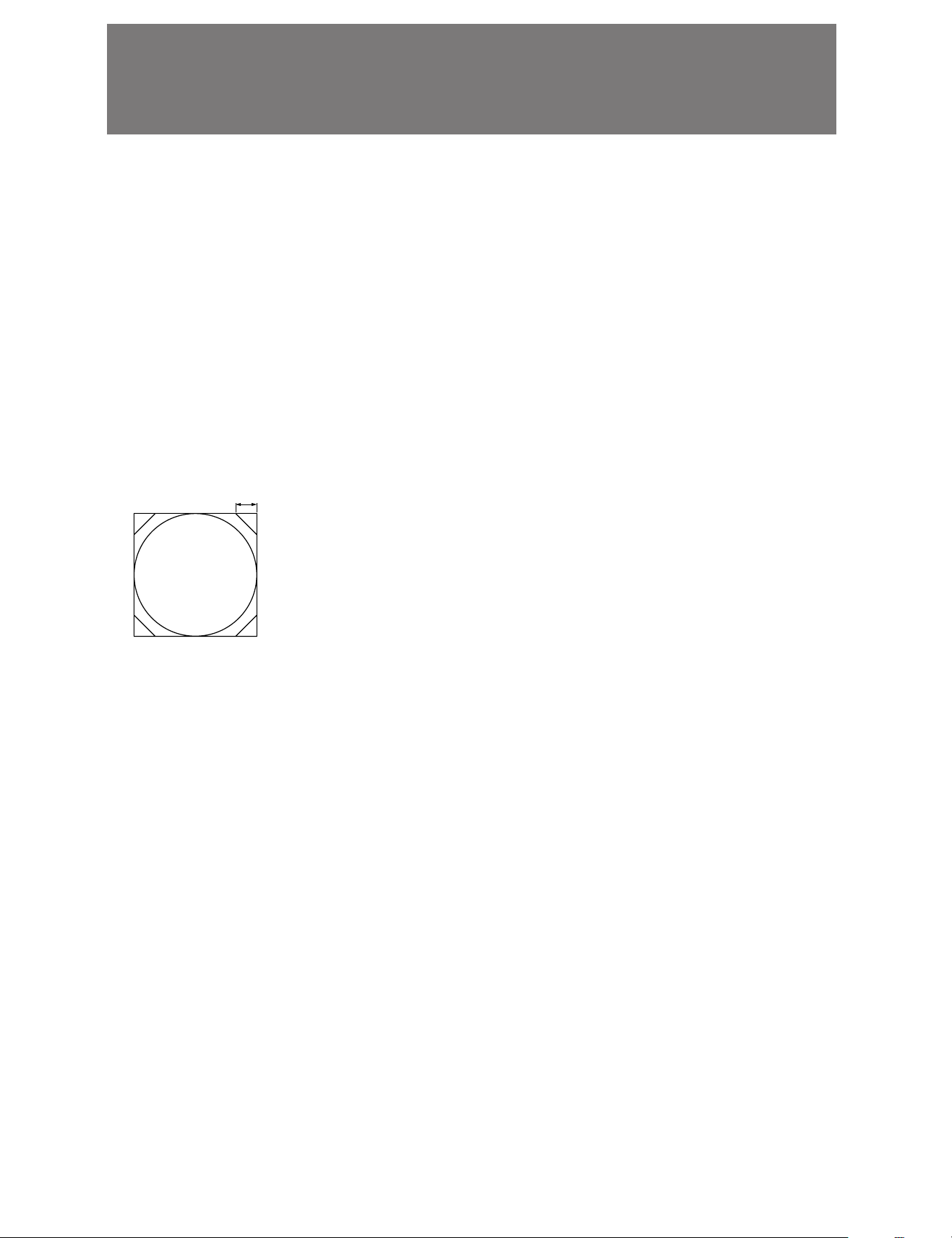
Geometric distortion
Within the area of a circle whose radius equals
1% of the picture height at all area of the pictrue.
Convergence Zone A : ≦0.013 inch
Zone B : ≦0.020 inch
Zone C : ≦0.030 inch
1''
C
B
A
Others
Operating temperature
0°C to 40°C (32°F to 104°F)
Operating humidity
10% to 80%
Storage temperature
–10°C to +60°C (14°F to 140°F)
Storage humidity
5% to 90%
Dimensions Approx. 673 × 673 × 760 mm
(26 1/2 × 26 1/2 × 30 inches)
Weight Approx. 95 kg (210 lb)
Optional accessaries
Remote controller DDM-RM10
Landing sensor DDM-LS10
Design and specifications are subject to change without notice.
Line width Zone A : ≦46 mils
Zone B, C : ≦52 mils (R,B)
≦46 mils (G)
Minimum recognizable character
0.1 inch
Inputs
Video inputs R.G.B:
BNC, 50 ohms terminated
0.714 Vp-p, positive
Sync inputs HD, VD:
BNC, 75 ohms terminated
TTL, negative
Power requirements
AC 90 to 132 V and 180 to 264 V,
50/60 Hz ±3 Hz
Power consumption
Maximum 450 W (500 VA)
5
 Loading...