

Page 1
2-590-764-11(1)
DVD Home Theatre
System
Operating Instructions
DAV-FX100W
©2005 Sony Corporation
Page 2
3
WARNING
To prevent fire or shock hazard, do not
expose the unit to rain or mo ist u r e.
Caution – The use of optical instruments
with this product will increase eye
hazard.
For the customers in the U.S.A
This symbol is int ended to alert the us er to
the presence of uninsulated “d an ge ro u s
voltage” within the p ro du ct ’ s e n clo s u r e th at
may be of sufficient magnitude to constitute a risk of
electric shock to persons.
This symbol is int ended to alert the us er to
the presence of important operating and
maintenance (servicing) instructions in the
literature accompanying the ap pliance.
Owner’s Record
The model and seria l numbers are lo cated at the botto m
of the unit. Record the serial number in the space
provided below. Refer to them whenever you call upon
your Sony dealer regarding this product.
Model No. DAV-FX100W
Serial No.______________
WARNING
This equipment has been tested and fou nd to co mply
with the limits for a Class B digital device, pursuant to
Part 15 of the FCC Rules. These limits are designed to
provide reasonable protection a gai nst harmful
interference in a residential installat ion. This
equipment generates, uses, and c an ra dia te radi o
frequency energy and, if not installed and used in
accordance with the instruc tions, may cause harmful
interference to radio commu nicati ons. However , ther e
is no guarantee that interference will not occur in a
particular installation. If thi s eq uipment does cause
harmful interference to radio or television reception,
which can be determined by turning the equipment off
and on, the user is encouraged to try to correct the
interference by one or more of the following measures:
– Reorient or relocate the rec eiv i n g antenna (aerial).
– Increase the separation between the equipment and
receiver.
– Connect the equipment into an outlet on a circuit
different from that to which the receiver is
connected.
– Consult the dealer or an experienced radio/TV
technician for help.
CAUTION
You are cautioned that any changes or modif icat ions
not expressly approved in this manual could void your
authority to operate this equipm ent .
Note to CATV system installer:
This reminder is provided to call the CATV system
installer’s attention to Article 820-40 o f th e N E C that
provides guidelines for proper ground ing a nd, in
particular, specifies that the cable ground shall be
connected to the grounding system of the building, as
close to the point of cable entry as practical.
For the customers in Canada
CAUTION
TO PREVENT ELECTRIC SHOCK, MATCH WIDE
BLADE OF PLUG TO WIDE SLOT, FULLY
INSERT.
Precautions
Safety
• If anything falls into the cabinet, unplug the unit and
have it checked by qualified per sonne l before
operating it any further.
• The unit is not disconnected from the AC power
source (mains) as long as it is connected to the wall
outlet (mains), eve n if the un it itself has been turned
off.
• Unplug the unit from the wall outlet (mains) if you do
not intend to use it for an extended period of time. To
disconnect the cord, pull it out by the plug, ne ver by
the cord.
Installing
• Allow adequate air circulation to prevent internal
heat buildup.
• Do not place the unit on surfaces (rugs, blanket s, etc.)
or near materials (curt ain s, dr aperies ) th at ma y blo ck
the ventilation slots.
• Do not install the unit near heat sources such as
radiators, or air ducts, or in a place subject to direct
sunlight, excessive dust, me c ha nic al vibration, or
shock.
• Do not install the unit in an inclined position. It is
designed to be operated in a horizontal position only.
US
2
Page 3

• Keep the unit and discs away from equipment with
strong magnets, such as microwave ove ns, or large
loudspeakers.
• Do not place heavy objects on the unit.
• If the unit is brought directly from a cold to a warm
location, moisture may conde nse insi de the DVD
Home Theatre System and cause damage to the
lenses. When you first install the unit, or when you
move it from a cold to a warm location, wait for about
30 minutes before operating th e unit.
®
ENERGY STAR
registered mark.
As an ENERGY STAR
Sony Corporation has determine d
that this product meets the ENERGY
®
guidelines for energy
STAR
efficiency.
is a U.S.
®
partner ,
Welcome!
Thank you for purchasing Sony DVD Home
Theatre System . B ef ore operating this sys te m ,
please read this manual tho ro u ghly and retain it
for future reference.
US
3
Page 4

Table of Contents
Welcome!................................................3
About This Manual................................. 6
This System Can Play the Following
Discs .................................................6
Guide to the Control Menu Display......10
Getting Started
Unpacking.............................................13
Inserting Batteries into the Remote.......13
Hookup Overview.................................14
Step 1: Speaker System Hook up...........15
Step 2: Antenna (Aerial) Hookup.........25
Step 3: TV Hookup............................. ..26
Step 4: Other Component Hookup........31
Step 5: Connecting the AC Power Cord
(Mains Lead)...................................33
Step 6: Turning off
the Demonstration...........................33
Step 7: Adjusting the Wireless
System ............................................34
Step 8: Performing the Quick Setup.....36
Speaker Setup........................................38
Playing Discs
Playing Discs........................................40
Using the DVD’s Menu........................45
Selecting [ORIGINAL] or [PLAY LIST]
on a DVD-RW.......................... .... ..46
Selecting a Playback Area for a Super
Audio CD........................................46
Playing VIDEO CDs with PBC Functions
(Ver.2.0)..........................................47
(PBC Playback)
About MP3 Audio Tracks and JPEG
Image Files .....................................48
Playing DATA CDs with MP3 Audio
Track and JPEG Image Files..........50
Playing Audio Tracks and Images as a
Slide Show with Sound...................52
Adjusting the Delay Between the Picture
and Sound.......................................54
(A/V SYNC)
Searching for a Particular Point on
a Disc..............................................55
(Scan, Slow-motion Play, Freeze
Frame)
Searching for a Title/Chapter/Track/
Scene, etc........................................ 56
Searching by Scene............................... 58
(Picture Navigation)
Viewing Information About the Disc... 59
Sound Adjustments
Changing the Sound .............................62
Enjoying Surround Sound by Using Sound
Field................................................ 64
Enjoying TV or VCR Sound from All
Speakers .........................................66
Using the Sound Effect.........................67
Using Various Additional
Functions
Changing the Angles.................. ... ....... 68
Displaying the Subtitles........................68
Locking Discs....................................... 69
(CUSTOM PARENTAL
CONTROL, PARENTAL
CONTROL)
Other Operations
Controlling the TV with the Supplied
Remote ...........................................73
Using the THEATRE SYNC
Function.......................................... 74
Enjoying the S ound of Other
Components....................................76
Enjoying Multiplex Broadcast Sound .. 76
(DUAL MONO)
Enjoying the Radio...............................77
Using the Sleep Timer..........................79
Changing the Brightness of the Front
Panel Display.................................. 80
Returning to the Default Settings.........80
US
4
Page 5

Settings and Adj ustments
Using the Setup Display........................81
Setting the Display or Sound Track
Language ........................................82
[LANGUAGE SETUP]
Settings for the Display.........................83
[SCREEN SETUP]
Custom Settings....................................85
[CUSTOM SETUP]
Settings for the Speakers.......................86
[SPEAKER SETUP]
Additional Information
Precautions............................................89
Notes about the Discs............................90
Troubleshooting....................................90
Self-diagnosis Function................ .... ... .94
(When letters/numbers appear in
the display)
Specifications........................................94
Glossary ................................................96
Language Code List..............................99
Index to Parts and Controls.................100
DVD Setup Display List.....................106
AMP Menu List..................................108
Index ...................................................109
US
5
Page 6

About This Manual
This System Can Play the
• The instructions in this manual describe the
controls on the rem ote. You can also use th e
controls on the system if they have the same or
similar names as those on the remote.
• The Control Menu items may be different
depending on the area.
• “DVD” may be used as a general term for
DVD VIDEOs, DVD+RWs/DVD+Rs, and
DVD-RWs/DVD-Rs.
• Measurements are expressed in feet (ft) for
North American models.
• The following symbols are used in this
manual.
Symbol Meaning
Functions available for DVD
VIDEOs, DVD-Rs/DVD-RWs in
video mode, and DVD+Rs/
DVD+RWs
Functions available for DVD-RWs
in VR (Video Recording) mode
Functions available for VIDEO
CDs (including Super VCDs or CDRs/CD-RWs in video CD format or
Super VCD format)
Functions available for Super Audio
CDs
Functions available for music CDs
or CD-Rs/CD- RWs in music CD
format
Functions available for DATA CDs
(CD-ROMs/CD-Rs/CD-RWs
containing MP3* audio track s an d
JPEG image files)
* MP3 (MPEG1 Audio Layer 3) is a standard format
defined by ISO/MPEG which compresses audio
data.
Following Discs
Format of
discs
DVD VIDEO
DVD-RW
VIDEO CD
Super Audio
CD
Audio CD
CD-R/CD-RW
(audio data)
(MP3 files)
(JPEG files)
The “DVD VIDEO” logo and “DVD-RW” logo are
trademarks.
Note about CDs
The system can play CD-ROMs/CD-Rs/CDRWs recor d e d in the follo wing formats:
– audio CD format
– video CD format
– MP3 audio tracks and JPEG image files of
format conform i ng to ISO 9660 Level 1 /
Level 2, or its extended format, Joliet
Disc logo
US
6
Page 7

Example of discs that the system cannot play
The system cannot play the following discs:
• CD-ROMs/CD-Rs/CD-RWs other than those
recorded in the formats listed on page 6
• CD-ROMs recorded in PHOTO CD format
• Data part of CD-Extras
• DVD Audios
• DVD-RAMs
However, since t he audio materia l side does no t
conform to the Compact Disc (CD) standard,
playback on th i s product is not guaranteed.
Note on PBC (Playback Control) (VIDEO CDs)
This system conforms to Ver. 1.1 and Ver. 2.0 of
VIDEO CD standards. You can enjoy two kinds
of playback depending on the disc type.
Also, the system can not play the following
discs:
• A DVD VIDEO with a different region code
(page 8, 98).
• A disc that has a non-standard shape (e.g.,
card, heart).
• A disc with p aper or stickers on it .
• A disc that has the adhesive of cellophane tape
or a sticker still left on it.
Notes about CD-R/CD-RW/DVD-R/
DVD-RW/DVD+R/DVD+RW
In some cases, CD-R/CD-RW/DVD-R/DVD-RW/
DVD+R/DVD+RW cannot be played on this system
due to the recording quality or physical condition of the
disc, or the characteristics of the recording device and
authoring software.
The disc will not play if it has not been correctly
finalized. For more informat ion, se e the ope r ating
instructions for the recor d ing device.
Note that discs created in the Packet Write format
cannot be played.
Music discs encoded with
copyright protection
technologies
This product is designed to play back discs that
conform to the Compact Disc (CD) standard .
Recently, various music discs encoded with copyright
protection technol o gies ar e mark eted by some record
companies. Please be aware that am ong those discs,
there are some that do not conform to the CD standard
and may not be playable by this product.
Note on DualDisc
A DualDisc is a two si de d disc product which
mates DVD recorded material on one side with
digital audio material on the other side.
Disc type You can
VIDEO CDs
without PBC
functions
(Ver. 1.1 discs)
VIDEO CDs
with PBC
functions
(Ver. 2.0 discs)
Enjoy video playback (moving
pictures) as well as music.
Play interactive software using
menu screens displayed on the
TV screen (PBC Playback ), in
addition to the video playback
functions of Ver. 1.1 discs.
Moreover, you can play highresolution still pictures, if they
are included on the disc.
About Multi Session CD
• This system can play Multi Session CDs when
an MP3 audio track is contained in the first
session. Any sub sequent MP3 audio tr acks
recorded in later sessions can also be played
back.
• This system can play Multi Session CDs when
a JPEG image file is contained in the first
session. Any sub sequent JPEG image files
recorded in later sessions can also be played
back.
• If audio tracks and images in music CD format
or video CD format are recorded in the first
session, only the first session will be played
back.
About the Super Audio CD
Super Audio CD is a new hi gh-quality audio
disc standard where music is recorded in the
DSD (Direct Stream Digital) format
(conventional CDs are recorded in the PCM
format). The DSD format, using a sampling
continued
US
7
Page 8
frequency 64 times hi gher than that of a
conventional CD, and with 1-bit quantization,
achieves both a wide frequency range and a wide
dynamic range across the audible f requency
range, and so pro vi des music reproduc ti on
extremely faithful to the original sound.
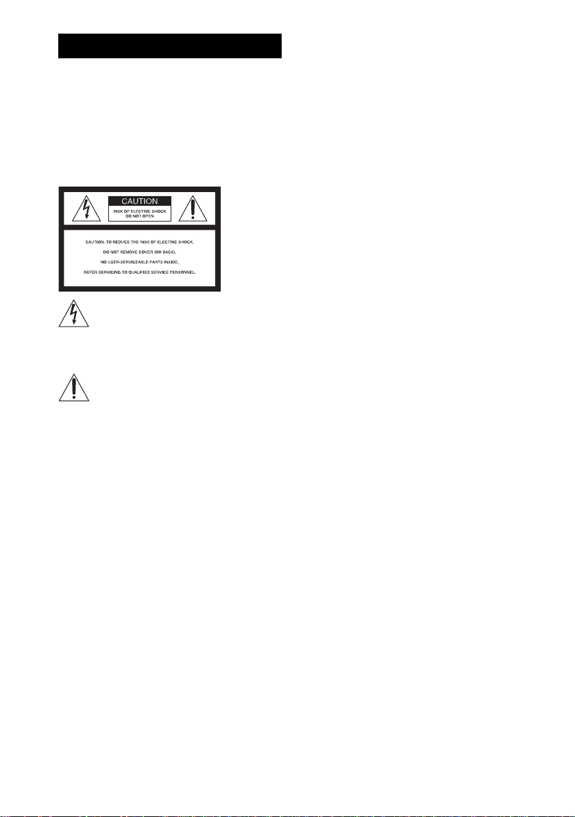
Types of Super Audio CDs
There are two types of discs, depending on the
Super Audio CD layer and CD layer
combination.
• Super Audio CD layer: A high-density
signal layer for Super Audio CD
•CD layer*
1
: A layer that is readable by a
conventional CD pl ayer
Single layer disc
(a disc with a single Super Audio CD layer)
Super Audio CD
layer
Hybrid disc*
(a disc with a Super Audio CD layer and a CD layer)
2
2 channel area*
Multi channel area*
*1You can play the CD layer on a conven tional CD
player.
*2Since both layers are on one side, it is not necessary
to turn the disc over.
*3To select a layer, see “Sel ecting a Play back Area for
a Super Audio CD” (page 46).
*4To select an area, see “S electing a Play back Area for
a Super Audio CD” (page 46).
4
4
Super Audio CD
layer
Region code
Your system has a region code printed on the
back of the unit and will only play DVDs labeled
with the same region code.
CD layer*
Super Audio CD
layer*
A Super Audio CD la ye r consists of the 2
channel area or th e m ul ti-channel area.
• 2 channel area: An area in which 2 channel
stereo tracks are recorded
• Multi-channel area: An area in which multichannel (up to 5. 1 channels) track s are
recorded
US
8
3
DVD VIDEOs labeled will also play on this
ALL
system.
3
If you try to play any other DVD VIDEO, the
message [Playback prohibited by area
limitations.] will appear on the TV screen.
Depending o n the DVD V IDEO, no re gion co de
indicati on may be given e ven though pl aying the
DVD VIDEO is prohibited by area restrictions.
Note on playba ck operations of DVDs and VIDEO CDs
Some playback operations of DVDs and VIDEO
CDs may be intentionally set by software
producers. Since this system plays DVDs and
VIDEO CDs according to the disc contents the
software pr oducers design ed , s ome playback
features may not be available. Also, refer to the
instructions supplied with the DVDs or VIDEO
CDs.
Page 9

Copyrights
This product i ncorporates copyright prot ection
technology that is protected by U.S. patents and
other intellectual property rights. Use of this
copyright protection technology must be
authorized by Macrovision, and is intended for
home and other limited viewing uses only unless
otherwise author ized by Macrovisio n. Reverse
engineer i ng or disassembly is prohibit ed.
This system incorporates with Dolby*
and Dolby Pro Logic (II) adaptive matrix
surround decoder and the DTS*2 Digita l
Surround System .
*1Manufact ured under license from Dolby
Laboratories.
“Dolby,” “Pro Logic,” and the double-D symbol are
trademarks of Dolby Laboratories.
*2Manufact ur ed under license from Digital Theate r
Systems, Inc.
“DTS” and “DTS Digital Surround” are trademarks
of Digital Theater Systems, Inc.
1
Digital
US
9
Page 10
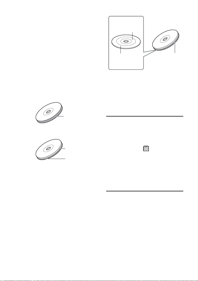
Guide to the Control Menu Display
DISPLAY
Use the Control Menu to select a function and to view related information. Press DISPLAY
repeatedly to turn on or change the Control Menu display as follows:
Control Menu display 1
,
m
Control Menu display 2 (appear s f or certa in discs only)
m
Control Menu display off
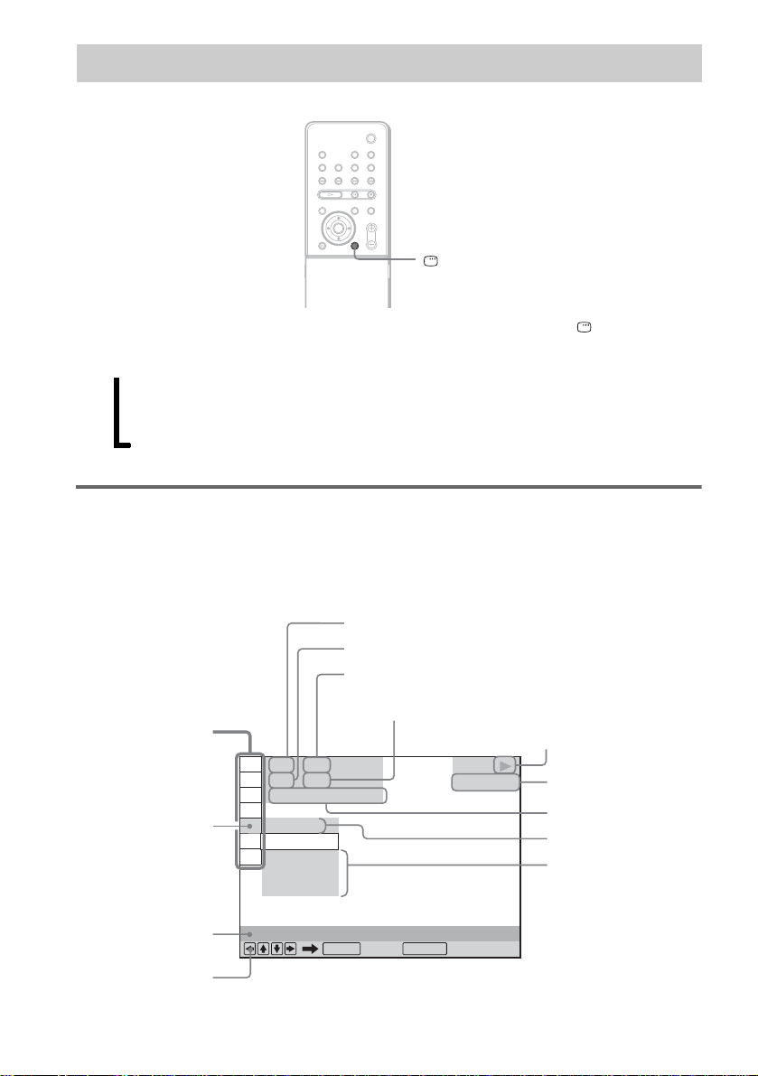
Control Menu display
The Control Menu display 1 and 2 will show different items depending on the disc type. For details
about each item, see the pages in parentheses.
Example: Control Menu display 1 when playing a DVD VIDEO.
Currently playing title number*
Currently playing chapter number*
Total number of titles*
Total number of chapters*
Control Menu items
)
)
1 : 3 2 : 5 5
Selected item
1 2 ( 2 7
1 8 ( 3 4
T
OFF
OFF
DISC
TITLE
CHAPTER
Function name of
10
selected Control
Menu item
Operation message
US
REPEAT
ENTER DISPLAY
Quit:
1
2
DVD VIDEO
1
2
Playback status
(N Playback, X
Pause,
x Stop, etc.)
Type of disc being
played*
Playing time*
Current setting
Options
3
4
Page 11
*1Displays the scene number for VIDEO CDs (PBC is on), track number for VIDEO CDs/Super Audio CDs/CDs,
album number for DATA CDs.
*2Displays the inde x number for VIDEO CDs/Super Audio CDs, MP3 audio track number, or JPEG image file
number for DATA CDs.
*3Displays Super VCD as “SVCD.” Displays “MP3” in the Control Menu display 1 or “JPEG” in the Control Menu
2 for DATA CDs.
*4Displays the date for JPEG files.
To turn off the display
Press DISPLAY.
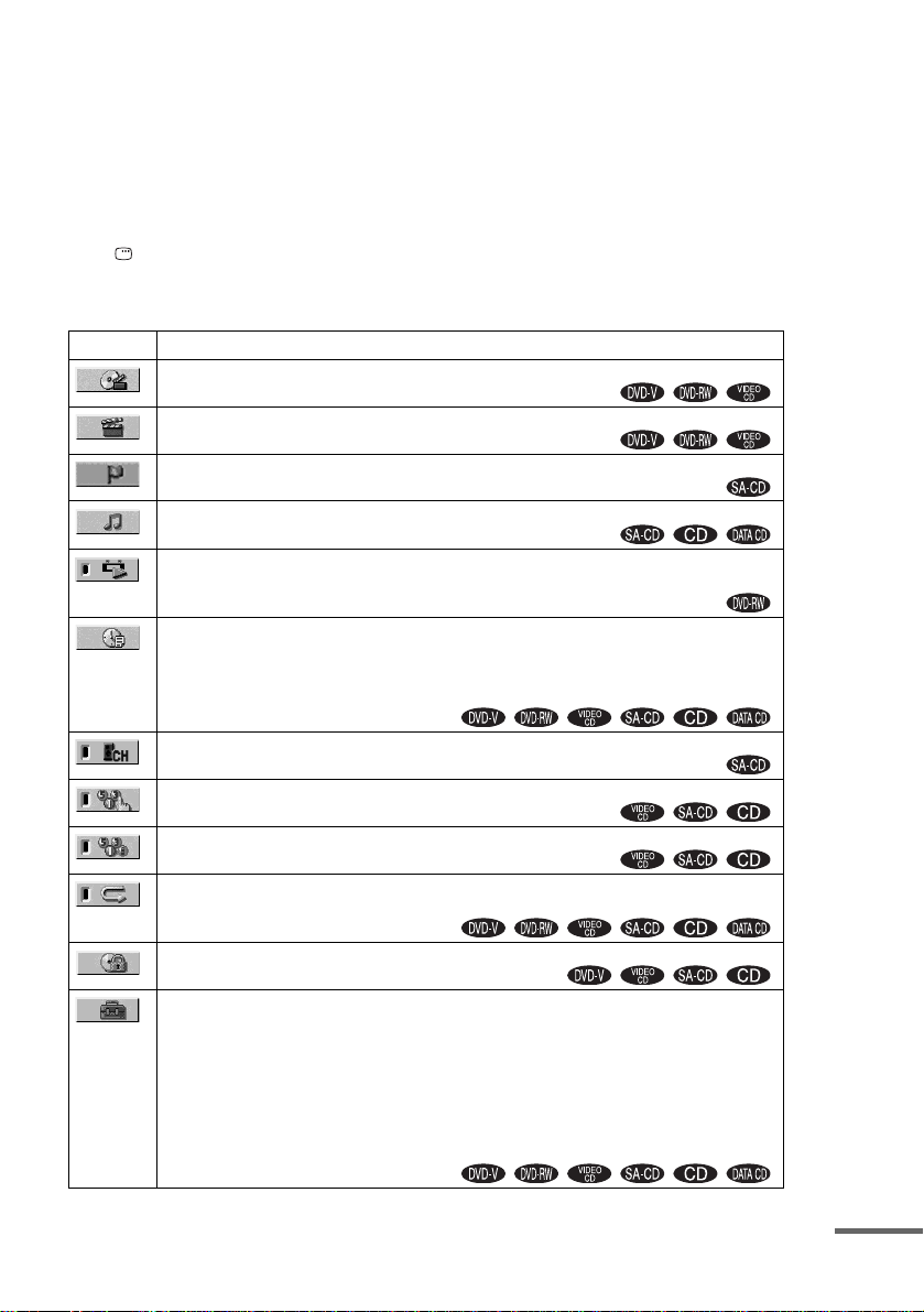
List of Control Menu items
Item Item Name, Function, Relevant Disc Type
[TITLE] (page 56)/[SCENE] (page 56)/[TRACK] (page 56)
Selects the title, scene, or track to be played.
[CHAPTER] (page 56)/[INDEX] (page 56)
Selects the chapter or index to be played.
[INDEX] (page 56)
Displays the index and selects the index to be played.
[TRACK] (page 56)
Selects the track to be played.
[ORIGINAL/PLAY LIST] (page 46)
Selects the type of titles (DVD-RW) to be played, the [ORIGINAL] one, or an edited [PLAY
LIST].
[TIME/TEXT] (page 57)
Checks the elapsed time and the remaining playback time.
Input the time code for picture and music searc h ing.
Displays the DVD/CD text or the MP3 track name.
[MULTI/2CH] (page 46)
Selects the playback area on Super Audio CDs when available.
[PROGRAM] (page 42)
Selects the track to play in the order you want.
[SHUFFLE] (page 43)
Plays the track in random orde r .
[REPEAT] (page 44)
Plays the entire disc (all titles/all tracks/all albums) repeatedly or one title/chapter/track/album
repeatedly.
[PARENTAL CONTROL] (page 69)
Sets to prohibit playback on this system.
[SETUP] (page 81)
[QUICK] Setup (page 36)
Use Quick Setup to choose the desired language of the on-screen display, the aspec t r at io of
the TV, and the size of the speakers you are using.
[CUSTOM] Setup
In addition to the Quick Setup setting, you can adjust various other settings.
[RESET]
Returns the settings in [SETUP] to the default setting.
continued
11
US
Page 12
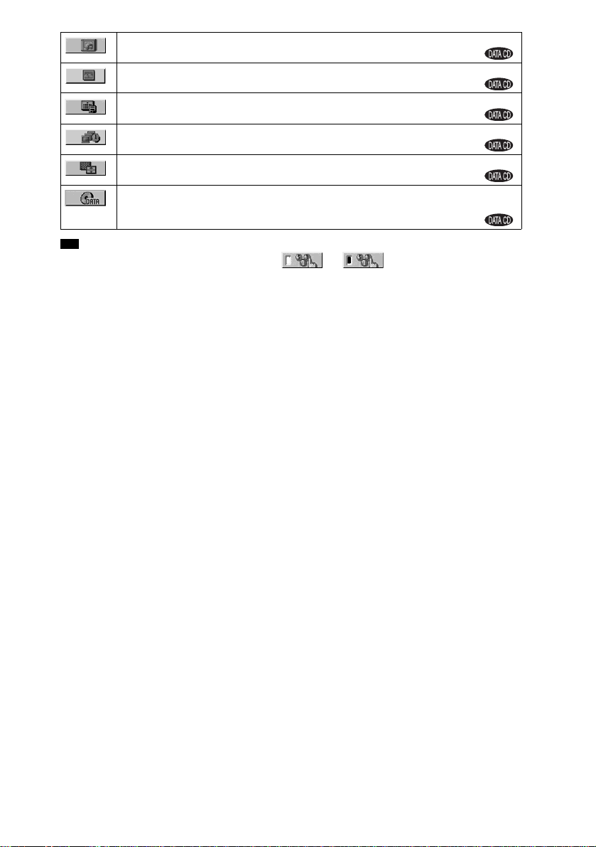
[ALBUM] (page 56)
Selects the album to be played.
[FILE] (page 56)
Selects the JPEG image file to be played.
[DATE] (page 61)
Displays the date the picture was taken by a digit al came ra.
[INTERVAL] (page 53)
Specifies the duration for which the slides are displayed on the screen.
[EFFECT] (page 54)
Selects the effects to be used for changing slides during a slide show.
[MODE (MP3, JPEG)] (page 52)
Selects the data type; MP3 audio track (AUDIO), JPEG image file (IMAGE) or both
(AUTO) to be played when playing a DATA CD
Tip
• The Control Menu icon indicator lights up in green when you select any item except [OFF]
t
([PROGRAM], [SHUFFLE], [REPEAT] only). The [ORIGINAL/PLAY LIST] indicator lights up in green when
you select [PLAY LIST] (default setting). The [M ULTI /2C H] indi cator lights up in green when you select the
multi-channel playback area on a Super Audio CD.
12
US
Page 13
Getting Started
Unpacking
Check that you have the following items:
•Speakers (5)
• Subwoofer (1)
• Posts (long × 4, short × 4)
• Bases (4)
• Terminal covers ( 4)
• Screws (20)
• Surround amplifier (1)
• IR transmitter* (1)
• IR receiver* (1)
• IR receiver stan d (1 )
• Speaker ba se (1)
• AM loop antenna (aer i al) (1)
• FM wire antenna (aerial) (1)
• Speaker cords (5 m × 6)
(16.5 ft. × 6)
• Video Cord (1)
• Remote Commander (remot e) (1)
• Size AAA (R03) batteries (2)
• Wall-mount pa ds
• Operating Instructions
• Speaker and TV connections (card) (1)
* The cords of the IR transmitter and IR receiver are
for this system only. You cannot use a commercially
available extension cord .
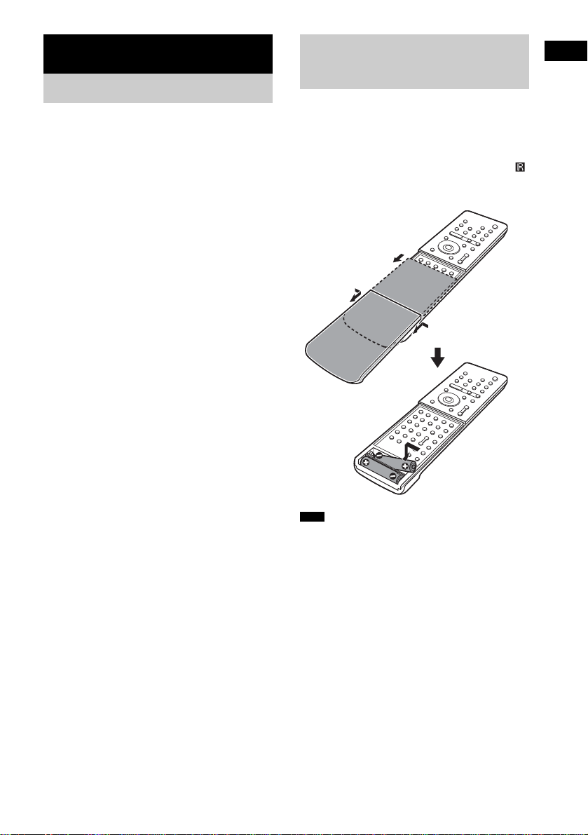
Inserting Batteries into the Remote
You can control the system using the supplied
remote. Insert two size AAA (R03) batteries b y
matching the 3 and # ends on the batteries to
the markings inside the compartment. When
using the remote, point it at the remote s ensor
on the system.
1 Slide open the c over.
2
2 Remove the
cover by pinching
the sides.
Note
• Do not leave the remote in an extremely hot or humid
place.
• Do not use a new battery with an old one.
• Do not drop any foreign object into the remote casing,
particularly when replac ing th e ba tteries.
• Do not expose the remote senso r to dir ect li ght from
the sun or lighting apparatus. Doi ng so ma y c au se a
malfunction.
• If you do not intend to use the remote for an extended
period of time, remove the batteries to avoid possible
damage from battery leakage and corros ion.
Getting Started
13
US
Page 14

Hookup Overview
Perform all connections and settings by following Steps 1 to 8.
“Step 1: Speaker System Hookup” (page 15)
“Step 2: Antenna (Aerial) Hookup” (page 25)
“Step 3: TV Hookup” (page 26)
“Step 4: Other Component Hookup” (page 31)
“Step 5: Connecting the AC Power Cord (Mains Lead)” (page 33)
“Step 6: Turning off the Demonstration” (page 33)
“Step 7: Adjusting the Wireless System” (page 34)
“Step 8: Performing the Quick Setup” (page 36)
Video signal is se nt to th e TV , and is output from the TV screen; audio signals are processed by th is
system and outpu t fro m the speakers of this sys t em . You can also enjoy sound of other sources, such
as TV programs, in ad di tion to DVDs or CDs.
14
US
Page 15
Step 1: Speaker System Hookup
Connect the supplied speaker system using the supplied speaker cords by matching the colors of the
jacks to those of the cords. Do not conn ect any speakers other than those supp lied with this system .
To obtain the best possible surround sound, specify the speaker parameters (distance, level, etc.) on
page 86.
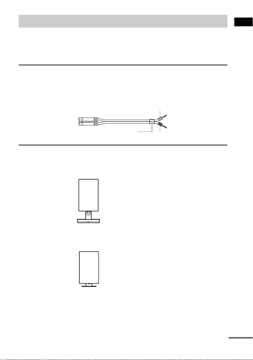
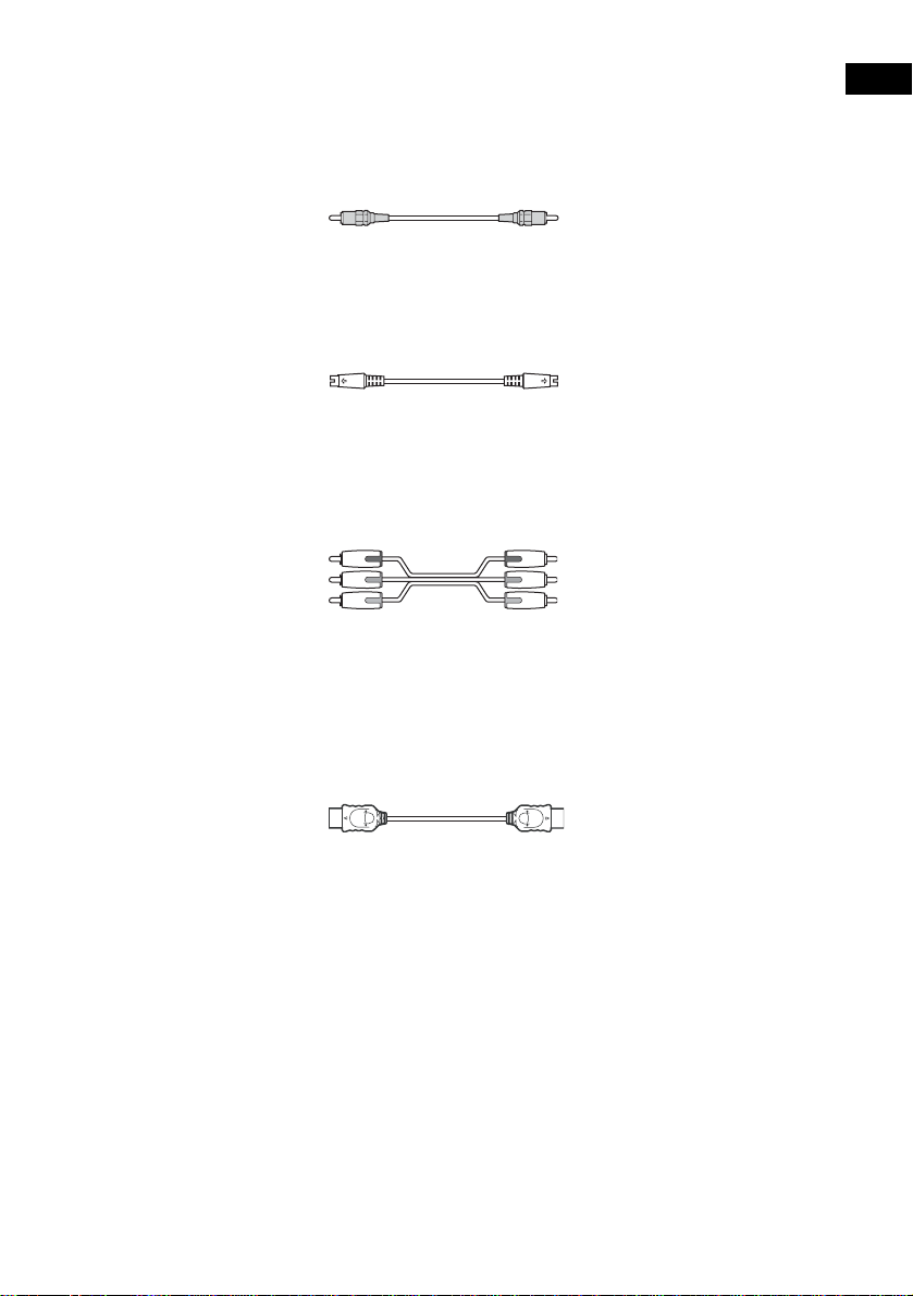
Required cords
Speaker cords
The connector and the color tube of the speaker cor ds are the same colo r as the label of the jacks to be
connected.
Gray
(+)
(–)
Color tube
Required equipments for the wireless system
IR transmitter
Transmits the sound by the infrared ray. Connect it to the system.
(+)
(–)
Black
Getting Started
IR receiver
Receive the sound by the infrared ray. Connect it to the surround amplifier.
continued
15
US
Page 16
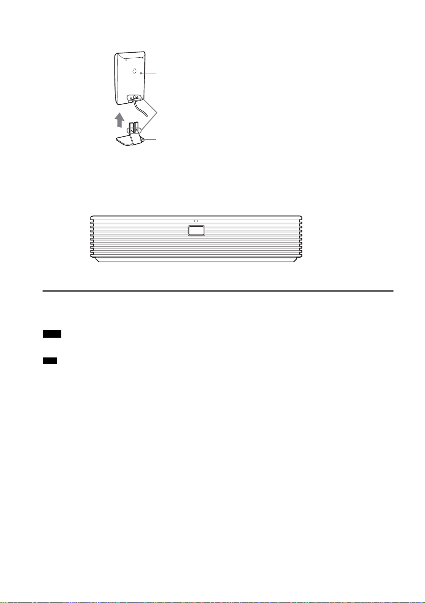
When using the IR receiver stand, attach th e stand so that bot h delta mar ks on the I R receiver and stan d
are aligned.
IR receiver
Delta marks
IR receiver stand
Surround amplifier
Receive the sound f rom the IR receiver a nd send to the surround speakers.
Connect the sur ro u nd speakers and the IR r eceiver to the surround amplifier.
POWER/ON LINE
POWER
Attaching the speaker stand to the speaker
Before conne cting the speaker s, attach the speaker st and to the speaker.
Note
• Spread a cloth on the floor to avoid damaging the floor.
Tip
• You can use the speaker without the spe aker sta nd by installing it on the wall (page 22).
1 Insert the post into the base.
16
US
Page 17
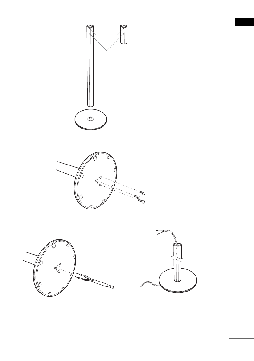
The long post is for floor use, the short post is for tabletop use.
Post (long)
or
Screw holes
Base
2 Secure the base to the post by screws.
Post (short)
Bottom of the base
Screws (3)
Getting Started
3 Draw the speaker cord through the hole on the base, then stand it up.
Bottom of the
base
,
Speaker cord
continued
17
US
Page 18
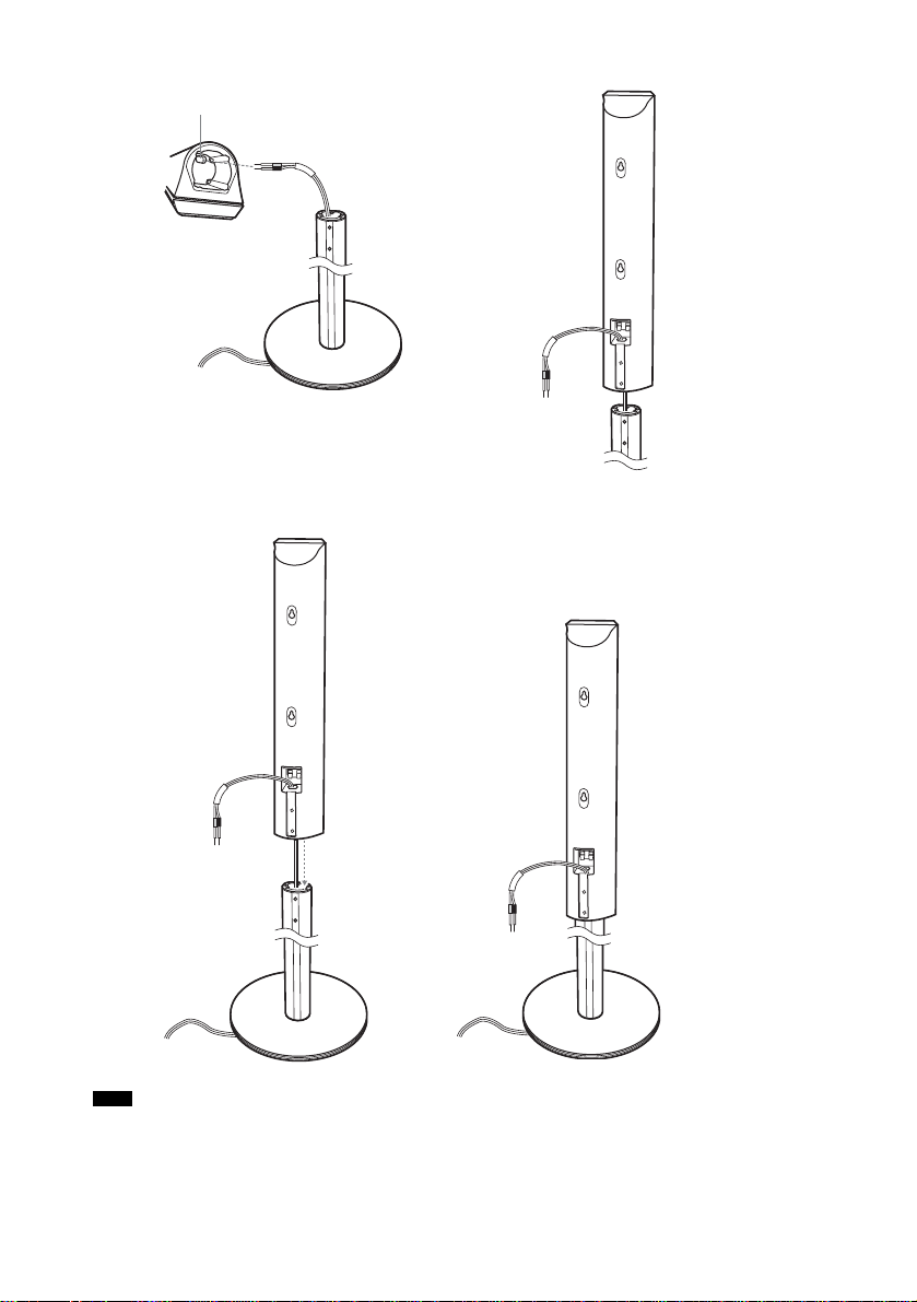
4 Draw the speaker cord through the hole on the speaker.
Hole
Speaker cord
Speaker
,
5 Mount the speaker on the post.
Speaker
,
Note
• Do not catch the speaker cord between the speaker and the post.
• Do not drop the speaker when mounting.
US
18
Page 19

6 Connect the speaker cord to the speaker, then adjust the length of the speaker cord.
Adjust the length of the speaker cord.
7 Attach the terminal cover to the speaker by screws.
Terminal cover
Getting Started
Screws (2)
19
US
Page 20
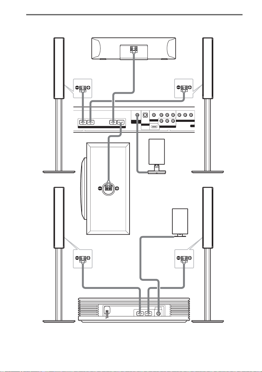
Connectin g the speakers
N
Front speaker (R)
Rear side of the front
speaker
FRONT R FRONT L CENTER WOOFER
SPEAKER
Center speaker
OPTICAL
DIR-T1
DIGITAL IN
VIDEO 2
HDMI
OUT
Rear side of the front
speaker
COAXIAL IN
AUDIO IN
RL
VIDEO 1
RL
AUDIO IN
VIDEO 2
(DVD ONLY)
IR transmitter
VIDEO IN
YPB/CBPR/C
COMPONENT VIDEO OUT
(DVD ONLY)
VIDEO IN
IR receiver
Front speaker (L)
R
MO
20
Subwoofer
Rear side of
the surround
speaker
Surround speaker (L)
US
Surround amplifier
Rear side of
the surround
speaker
SPEAKER DIR-R2
SURROUND L SURROUND R
Surround speaker (R)
Page 21
Note
• Do not set the speakers in an inclined posit ion.
• Do not place the speakers in lo cations that are:
– Extremely hot or cold
– Dusty or dirty
– Very hum id
– Subject to vibrations
– Subject to direct sunlight
• Use caution when placing t h e speakers and/or speaker stands (n o t supp lied) that are attached with th e s p eak ers on
a specially treated (waxed, oi l ed , po l is h ed , et c.) floor, as staining or discoloration may result.
• When cleaning, use a soft cloth such as a cleaning cl oth f or glasse s.
• Do not use any type of abrasive pad, scouring powder, or solvent such as alcohol or benzin e.
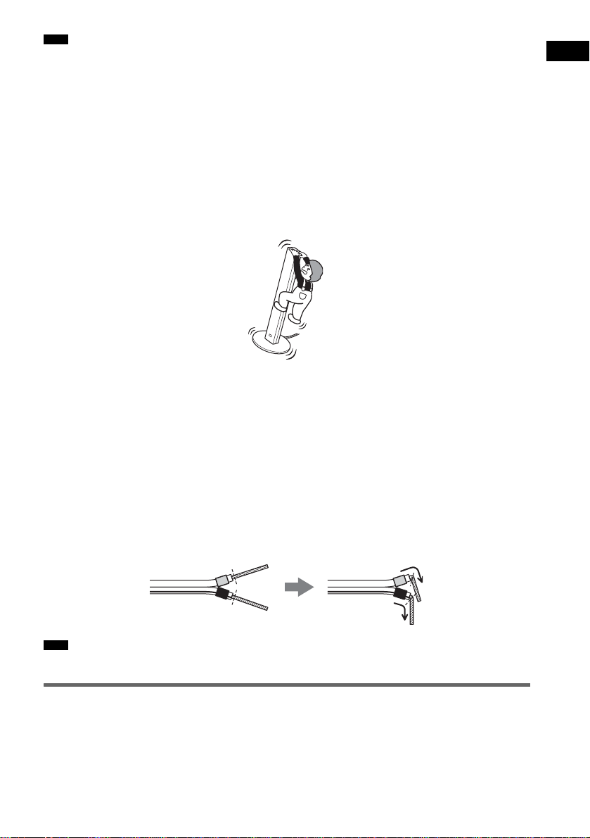
• Do not lean or hang on the speaker, as the speaker may fall down.
Notes on placing IR transmitter and IR receiver
• Do not install the IR receiver in a place exposed to direct sunlight or strong light such as an incandescent lamp.
• The cords of the IR transmit ter and IR receiver are for this syst em o nl y . Yo u ca nnot use a commercially available
extension cord.
Notes on placing the surround amplifier and speaker base
• Do not step and place objects other than supplied speakers on the surround amplif ie r and spe a ke r base .
• When you install the speaker on the surround amplifier or speaker base, make sure the speaker is properly stacked.
To connect the speaker cords
Connect the speaker cords after bending the bare wire at the end of the insulation. This prevents the
speaker insulation from being inserted in the speaker terminal.
Getting Started
Note
• Do not catch the speaker cord insulation in the SPEAKER jack.
Avoiding short-circuiting the speakers
Short-circuiting of the speakers may damage the system. To prevent this, be sure to follow these
precautions when connecting the speakers. Make sure the bare wire of each speaker cord does not touch
another speaker terminal or the bare wire of another speaker cord.
21
US
Page 22

Examples of poor conditions of the speaker cord
Stripped speaker cord is
touching another speaker
terminal.
Stripped cords are touching each
other due to excessive removal of
insulation.
After connectin g al l the components, speakers, and AC power cord (mains lead), out put a test tone to
check that all the speakers are connected correctly. For details on outputting a test tone, see page 87.
If no sound is heard from a speaker while outputting a test tone, or a test tone is output from a speaker
other than the one currently displayed on the Setup Display, the speaker may be short-circuited. If this
happens, check the speaker connect i on again.
Note
• Be sure to match the sp eaker co rd to the appropr iate termi nal on the c omponent s: 3 to 3, and # to #. If the cords
are reversed, the sound will lack bass and may be distorted.
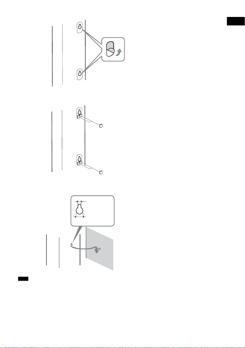
Installing the speakers on the wall
1 Prepare screws (not supplied) that are suitable for the hole on the back of each speaker.
See the illustrations below.
Hole on the back of
the speaker
25 mm (1 inch)
4 mm (
5
/32 inch)
4.6 mm
3
/16 inch)
(
10 mm
13
/32 inch)
(
2 Fasten the screws to the wall.
The screws should protrude 7 to 8 mm (9/32 to 11/32 inch).
165 mm (6 1/2 inch)
7 to 8 mm
9
(
/32 to 11/32 inch)
3 Peel the seals off the two screw points on the rear of the speaker.
22
US
Page 23
4 Attach the wall-mount pads on the rear side of the speaker.
Wall-mount pads
(7 × 7 mm, 3 mm thick)
9
(
/32 × 9/32 inch, 1/8 inch thick)
5 Hang the speakers on the screws.
Getting Started
4.6 mm
3
(
/16 inch)
10 mm
13
/32 inch)
(
Note
• Use screws that are suitable for the wall material and strength. As a plaster board wall is especially fragile, attach
the screws securely to a beam and fasten them to the wa ll . In st al l the speak ers on a vertical and flat wall where
reinforcement is applied.
• Contact a screw shop or installer regarding the wall material or screws to be used.
• Sony is not responsible for acci de n t or d amage caused by improper installation, insufficient wall strength or
improper screw insta lla tion, natural calamity, etc.
Hole on the back of
the speaker
23
US
Page 24

About the wireless system
This wireless system adopts the Digital Infra red Audio Transmission sy stem (page 96). The following
diagram indic at es the infrared tran sm i ssion area (the range that the infrare d rays can reach).
Top view
IR transmitter
Note
Infrared signal
10
10
Approx. 10m
IR receiver
Side view
IR transmitter
Infrared signal
10
10
Approx. 10m
IR receiver
• Do not install the IR receiv er in a place exposed to direct sunlight or str ong li ght such as an incandescent lamp.
• Do not use the IR transmitter or IR receiver th at is not supplied with the sys te m.
24
US
Page 25
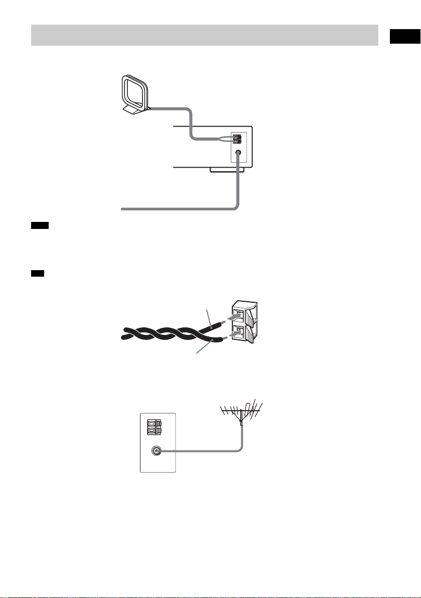
Step 2: Antenna (Aerial) Hookup
Connect the supplied AM/FM antennas (aerials) for listening to the radio.
AM loop antenna (aerial)
FM wire antenna (aerial)
Note
• To prevent noise pickup, keep the AM lo op an te nna (ae ri a l) awa y from the system and other components.
• Be sure to fully extend the FM wire antenna (aerial).
• After connecting the FM wire ant enn a (a erial), keep it as horizontal as possi ble .
Tip
• When you connect th e sup plied AM loo p ante nna (aerial ), cord (A) or co rd (B) can be connec te d to eithe r term inal .
A
Getting Started
B
• If you have poor FM reception, use a 75-ohms coaxial cable (not supplied) to connect the system to an outdoor FM
antenna (aerial) as shown below .
System
Outdoor FM antenna (aerial)
25
US
Page 26
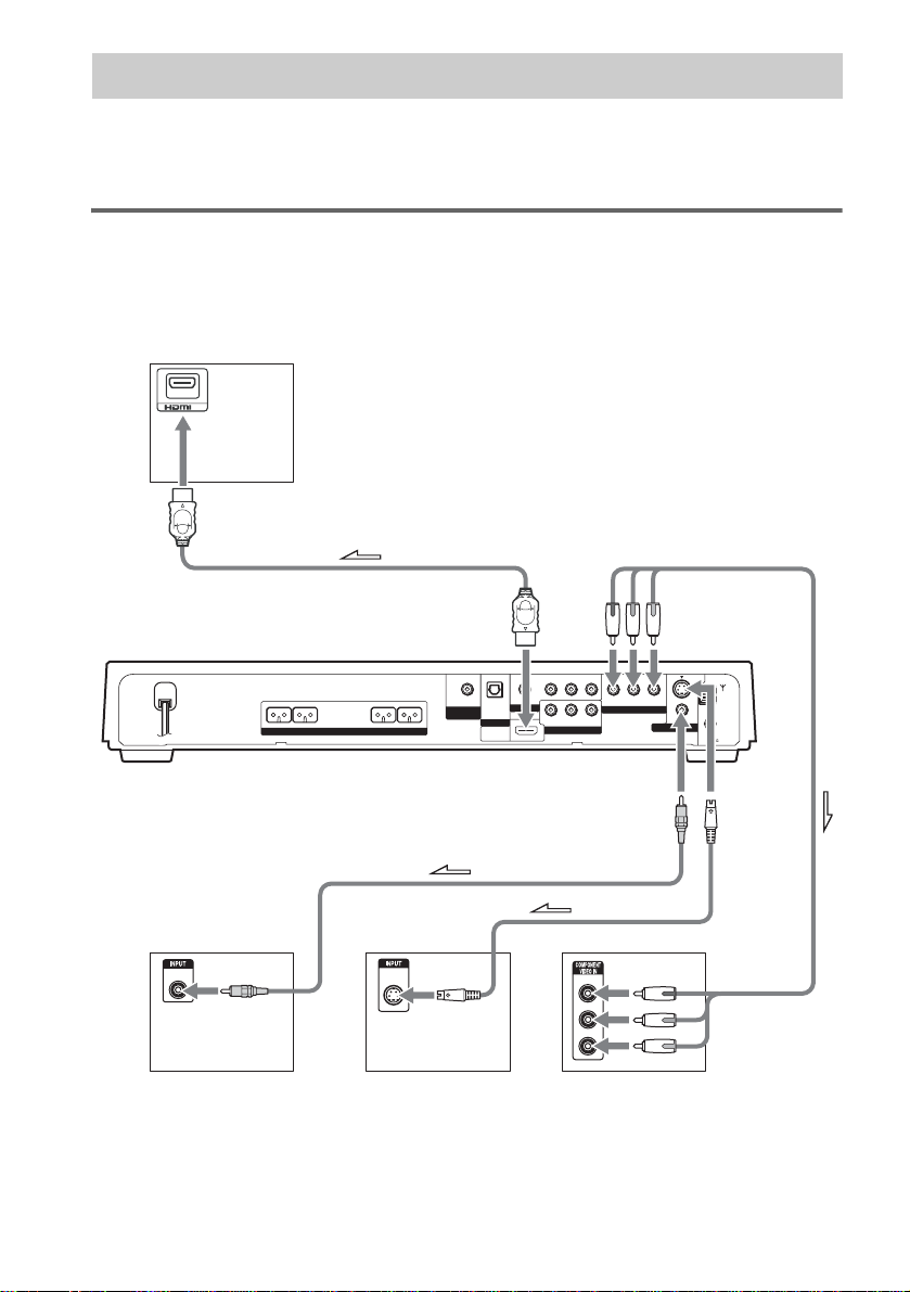
Step 3: TV Hookup
First, perform the video connection, and then audio connection.
With your TV’s audio output connected to this system, you can listen to TV sound through the system
speakers.
Connecting t he video/HDMI* cords
Sends a played back D V D image to a TV.
Check the jacks of your TV, and choose the A, B, C, or D connection. Picture quality improves in
order from A (standard) to D (component).
TV with HDMI* IN jack
IN
D
FRONT R FRONT L CENTER WOOFER
AB C
VIDEO
IN
TV TV with S VIDEO IN jack
* HDMI (high-definition multimedia interface)
The system is based on version 1.1 of High-De f ini tion Multimedia Interface Speci fications.
US
26
SPEAKER
To HDMI* OUT
S VIDEO
IN
To COMPONENT
VIDEO OUT
(DVD ONLY)
R
VIDEO
MONITOR OUT
S VIDEO
(DVD ONLY)
COAXIAL
FM
AM
75
To
S VIDEO
AUDIO IN
RL
RL
AUDIO IN
VIDEO 2
VIDEO IN
COMPONENT VIDEO OUT
VIDEO IN
YPB/CBPR/C
COAXIAL IN
VIDEO 1
OPTICAL
DIR-T1
DIGITAL IN
VIDEO 2
HDMI
(DVD ONLY)
OUT
To VIDEO
Y
PB/CB
PR/CR
TV with COMPONENT
TV with COMPONENT
VIDEO IN jacks
VIDEO IN jacks
Page 27
The system incorporates High-Defi n it i on Multimedia Interface (HDMITM) technology.
HDMI, the HDMI logo and High-Definition Multimedia Interface trademarks or registered trademarks of HDMI
Licensi ng LLC.
A To connect to a TV with the VIDEO IN jacks
Connect the video co rd.
Yellow
B To connect to a TV with the S VIDEO IN jack
Connect an S video cor d (not supplied). When using the S video jack instead of the video jac ks, your
TV monitor must also be connected via an S video jack. S video signals are on a separate bus from the
video signals and wi l l not be output throug h th e vi deo jacks.
C To connect to a TV with the COMPONENT VIDEO IN jacks
Connect a component video cord (not supplied). To use the COMPONENT VIDEO OUT jacks (Y, PB/
C
B, PR/CR) instead of the video jacks, your TV monitor must be equipped with via COMPONENT
VIDEO IN jacks (Y, P
B/CB, PR/CR). If your TV acce pts progressiv e fo rm at signals, you m ust use this
connection and set th e output channel of the system to progress iv e format (page 28).
Green
Blue
Red
D To connect to a TV with the HDMI (high-definition multimedia
interface)/DVI (digital visual interface) input jack
Use a certified HDMI (hig h -d ef i ni tio n mul timedia interface) cord (n ot su pp lied) to enjoy high quality
digital picture and sound through the HDMI OUT (high-definition multimedia interface out) jack.
Note that Super Audio CD sound is not output from the HDMI OUT (high-definition multimedia
interface out) jack.
Getting Started
To connect to a TV with DVI (digital visual interface) input
Use an HDMI (high-definition multime dia interfac e)-DVI (digital visu al interface) co nverter cord (not
supplied) with an HDMI (high-d ef ini tio n multimedia interface)-DVI (digital visual interface) adapto r
(not supplied). The DVI (digit al visual interface) jack wil l no t accept any audio s ignals. Furtherm ore,
you cannot connect the HDMI OUT (high-definition multimedia interface out) jack to DVI (digital
visual interface) jacks that are not HDCP (high-b and widt h digi tal content protection) compliant (e.g.,
DVI (digital visual interface) jacks on PC displays).
When connecting to a standard 4:3 screen TV
Depending on the disc, the image may not fit yo ur TV screen.
To change the aspect rat i o, see page 83.
27
US
Page 28
Does your TV accept progressive signals?
Progressive is the method for displaying TV images which reduces flickering, and sharpens the image.
To display using thi s m e thod, you need to connect to a TV that accepts pro gr essive signals.
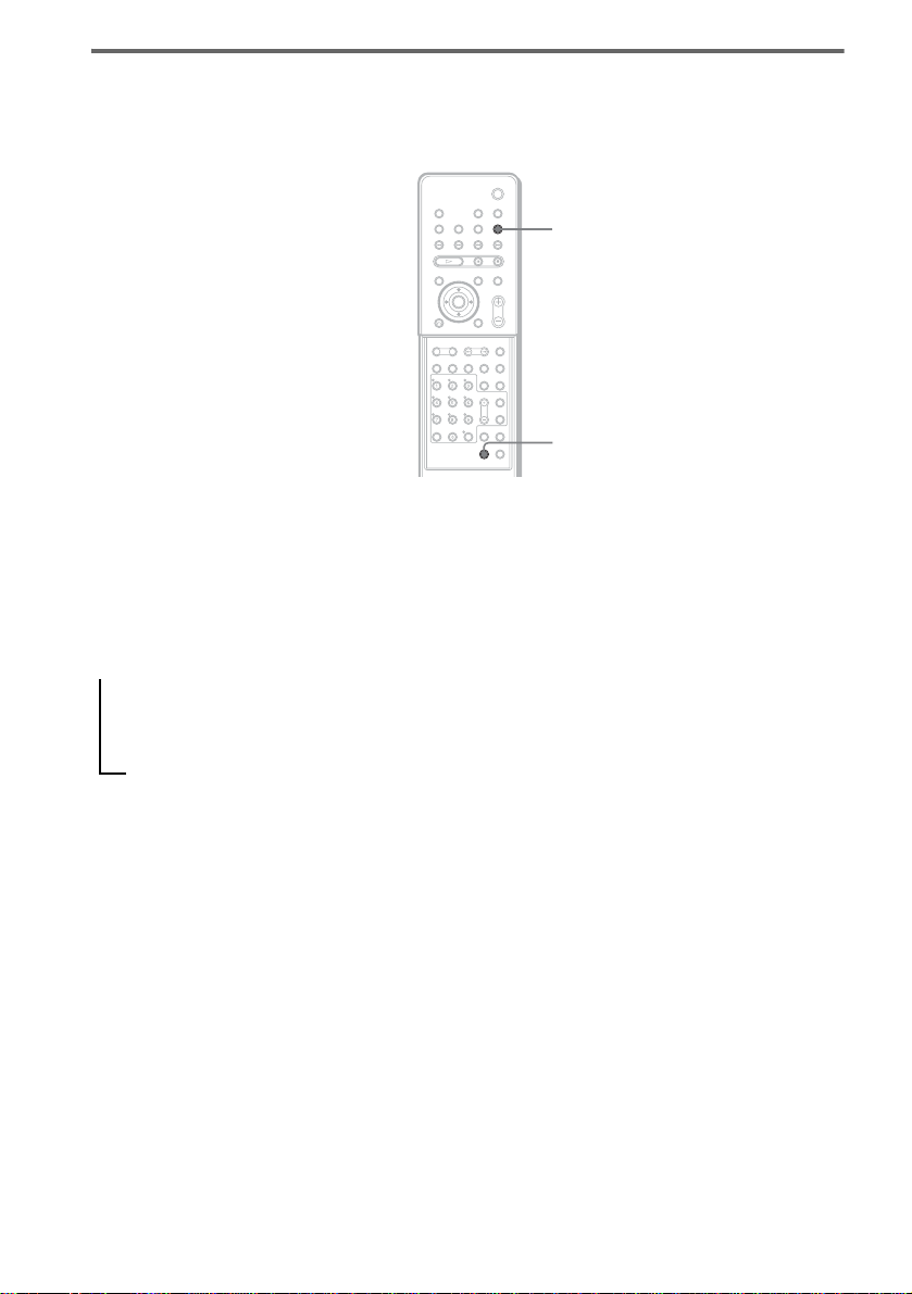
FUNCTION
PROGRESSIVE
With cover opened.
“P AUTO” or “P VIDEO” appears in the front panel display w hen the system outputs progressive
signals.
1 Press FUNCTION repeatedly to select “DVD.”
2 Press PROGRESSIVE.
Each time you press PROGRESSIVE, the display changes as follows:
t P AUTO (PROGRESSIVE AUTO)
r
P VIDEO (PROGRESSIVE VIDEO)
r
INTERLACE
28
x P AUTO (PROGRESSIVE A UT O )
Select this setting when:
– your TV accepts progress iv e si gnals, and,
– the TV is connected to the COMPONENT VIDEO OUT jacks.
Normally select this under the above condition. This automaticall y detects the software type, and
selects the appropriate conversion method.
Note that the pictur e w i ll not be clear or no pict ur e w ill appear if you selec t these settings when
either of the above conditions is not met.
x P VIDEO (PROGRESSIVE VIDEO)
Select this setting when:
– your TV accepts progress iv e si gnals, and,
– the TV is connected to the COMPONENT VIDEO OUT jacks, and,
– y ou want to fix the conversion method to PROG R ESSIVE VIDEO for vide o-based software .
Select this if the image is not clear when you select PROGRESSIVE AUTO.
Note that the pictur e w i ll not be clear or no pict ur e w ill appear if you selec t these settings when
US
Page 29
either of the above conditions is not met.
x INTERLACE
Select this setting when:
– your TV does not accept progressive signals, or,
– your TV is connected to jacks other than the COMPONENT VIDEO OUT jacks (MONITOR
OUT (VIDEO/S VIDEO)).
About DVD software types and the conversion method
DVD software can be divided into 2 types: film-based software and video-based software.
Video-based software is derived from TV, such as dramas and sit-coms, and displays images at 30
frames/60 f ields per s econd. Fi lm-based software is derived f rom film an d display s images at 24 frames
per second. Some DVD software contains both video and film.
In order for these i mages to appear na tural on your scree n w hen output in progr essive format, th e
progressive signal s need to be converted to match the type of DVD sof tware that you are watc hing.
Note
• When you play video-based software in prog ress ive signal format, sections of some types of ima ge s ma y app ear
unnatural due to the conversion process when output through the COMPONENT VIDEO OUT jacks. Even though
you set to “PROGRESSIVE AUTO” or “PROGRESSIVE VIDEO,” images from the MONITOR OUT (VIDEO or
S VIDEO) jack are unaffected as they are output in th e in t e rl ace format.
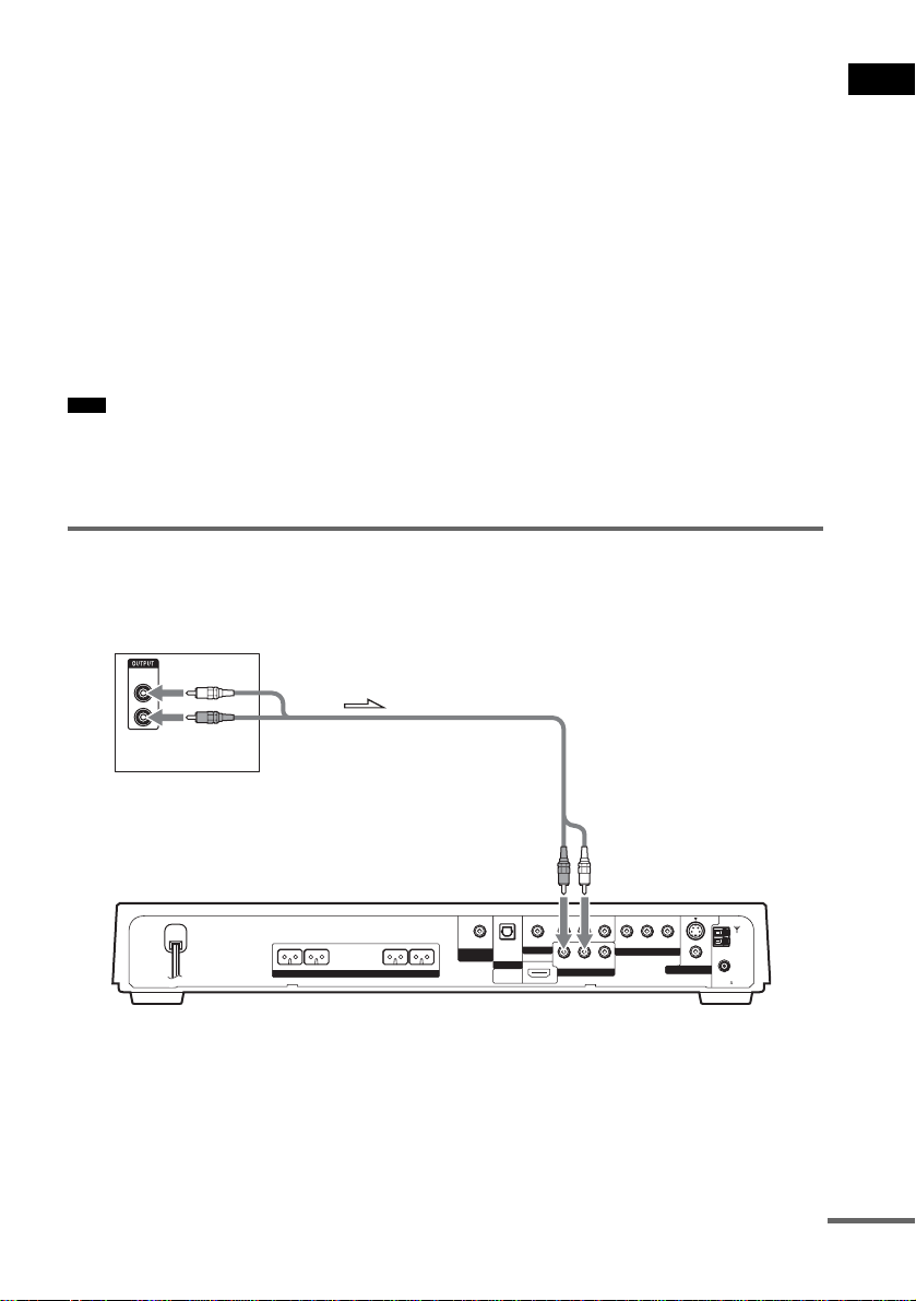
Connecting the audio cords
Outputs TV sound through the speake rs of this system.
TV
AUDIO
OUT
L
R
Getting Started
To VIDEO 2
(AUDIO IN)
R
VIDEO
MONITOR OUT
S VIDEO
(DVD ONLY)
COAXIAL
FM
AM
75
FRONT R FRONT L CENTER WOOFER
SPEAKER
AUDIO IN
RL
RL
AUDIO IN
VIDEO 2
VIDEO IN
YPB/CBPR/C
COMPONENT VIDEO OUT
VIDEO IN
(DVD ONLY)
COAXIAL IN
VIDEO 1
OPTICAL
DIR-T1
DIGITAL IN
VIDEO 2
HDMI
(DVD ONLY)
OUT
To connect the AUDIO OUT jacks of a TV to the VIDEO 2 (AUDIO IN)
jacks of this system
Connect a TV to the VIDEO 2 (AUDIO IN) jacks using an audio co rd (not supplied ). When connecting
a cord, be sure to match the color-coded sleeves to the appropriate jacks on the component s.
continued
29
US
Page 30

White (L/audio)
Red (R/audio)
Note
• Be sure to make connections sec ur el y to a void hum and noise.
• If your TV does not have AUDIO OUT jacks, you cannot output the TV sound from the speakers of this system.
Tip
• To listen to the TV sound, select the funct ion by pressing FUNCTION. For details, see page 66.
• When you want to output the TV sound or stereo sound of a 2 channel source from the 6 speakers, select the “Dolby
Pro Logic,” “Dolby Pro Logic II MOVIE,” or “Dolby Pro Logic II MUSIC ” sound f ield ( page 64).
30
US
Page 31

Step 4: Other Component Hookup
You can enjoy other component by connecting the VIDEO/AUDIO OUT jacks of another co mponent.
Connecting the system and the other component
Outputs the other component through the speakers of thi s system.
VCR
COAXIAL
DIGITAL
OUT
VIDEO
OUT
AUDIO
OUT
L
R
Getting Started
OPTICAL
DIGITAL
OUT
Digital satellite receiver or
PlayStation 2, etc.
VIDEO
OUT
AUDIO
OUT
L
R
FRONT R FRONT L CENTER WOOFER
SPEAKER
To VIDEO 2
(OPTICAL DIGITAL IN)
To VIDEO 1
(COAXIAL IN)
OPTICAL
DIR-T1
DIGITAL IN
VIDEO 2
HDMI
COAXIAL IN
RL
VIDEO 1
RL
(DVD ONLY)
OUT
AUDIO IN
AUDIO IN
VIDEO 2
VIDEO IN
COMPONENT VIDEO OUT
VIDEO IN
To VIDEO 1
(VIDEO/AUDIO IN)
R
VIDEO
MONITOR OUT
S VIDEO
(DVD ONLY)
COAXIAL
FM
AM
75
YPB/CBPR/C
(DVD ONLY)
To VIDEO 2
(VIDEO/AUDIO IN)
To connect the VIDEO/AUDIO OUT jacks of other component to the
VIDEO 1 or VIDEO 2 (VIDEO/AUDIO IN) jacks of this system
Connect the VCR or other components to the VIDEO 1 or VIDEO 2 (VIDEO/AUDIO IN) jacks using
the video/ audi o cord ( not su ppli ed). When con necti ng a co rd, be sure to match t he co lor-c oded s leev es
to the appropriate jacks on the components.
Yellow (Video)
White (L/audio)
Red (R/audio)
If you connect a digital satellite receiver with an DIGITAL OUT
(COAXIAL or OPTICAL) jack
The digital satellite receiver can be connected to the VIDEO 1 COAXIAL IN or VIDEO 2 OPTICAL
DIGITAL IN jack instead of the VIDEO 1 or VIDEO 2 AUDIO IN jacks of the system.
The system can accept both the digital and analogue signals. Digital signals have priority over analogue
signals. If the digi t al signal ceases, t he analogue signal w ill be processed after 2 seconds.
31
US
Page 32

If you connect a digital satellite receiver without an DIGITAL OUT jack
Connect the digital satelli te receiv er to t he VIDEO 1 or VIDEO 2 AUDIO IN j acks onl y of th e system.
Note
• Be sure to make connections sec ur el y to a void hum and noise.
Tip
• When you connect another component to the system, you can enjoy the component by pressing FUNCTION
(page 76).
32
US
Page 33

Step 5: Connecting the AC Power Cord (Mains Lead)
Before connecting the AC power cord (mains
lead) of th is system to a wall outlet (mains),
connect the speakers to the system (page 15).
"/1
"/1
To turn on the system
Press "/1.
To turn off the system
Press "/1. The system enters stan dby mode.
While playing a disc, do not turn off the system
by pressing "/1. Doing so may cancel the menu
settings. When you turn off the system, first
press x to stop pl ayback and then pres s "/1.
Step 6: Turning off the
Getting Started
Demonstration
"/1
X/x/c
ENTER
AMP MENU
With cover opened.
After connecting the AC power cor d (m ains
lead), the demonstration appears in the front
panel display. When you press "/1 on the
remote, the demonstration turns off.
Note
• When you press "/1 on the system, the demonstration
does not turn off.
• When you set the demonstr a tion mode in the AMP
menu to on, the demonstration does not turn off even
though you press "/1 on the rem ote. To turn off the
demonstration, set the demonstration mode to off,
then press "/1 on the remote.
Setting the demonstration mode on/off
1 Press AMP MENU.
2 Press X/x repeatedly until “DEMO”
appears in the front panel display, then
press ENTER or c.
3 Press X/x to select the setting.
• DEMO OFF: sets the demonstration mode
off.
• DEMO ON: sets the demonstration mode
on.
4 Press ENTER or AMP MENU.
The AMP menu turns off.
33
US
Page 34

Step 7: Adjusting the Wireless System
After connecting the speakers, surround
amplifier, IR transmitter, IR receiver, and the
AC power cords (mains leads), adjust the
wireless system for good transmission.
"/1
Example for installation
Position the IR transmitter and IR receiver as
illustrated.
Install the IR transmitter and IR receiver in
direct line with each other, and adjust the
orientation of the IR tra nsmitter and IR re ceiver
until the POWER/ON LINE indicator turns
green.
Top view
IR transmitter
POWER/
ON LINE indicator
POWER
POWER/ON LINE
POWER
1 Press "/1 on the system and POWER
on the surround amplifier.
The system and surround amplifier tur n on
and the POWER/ON LINE indicator turns
red.
2 Orient the IR transmitter and IR
receiver to face each other.
Adjust the position until the POWER/ON
LINE indicator turns green.
Tip
• The IR transmitter is movable for easy reorient ati o n.
Note
• Make sure that there is no obstr uc tion such as a
person or object between the IR transmitter and the IR
receiver. Otherwise, the sound from the surround
speakers may be interrupted.
• If the POWER/O N LIN E indicator turns red, th e
transmission is incomplete. Adjust the position of the
IR transmitter and IR receiver until the POWER/ ON
LINE indicator turns green.
• If the POWER/ON LINE indicator flashes in red, the
IR receiver is receiving an infr ared ray from another
Sony’s wireless product. Mov e the IR transmitter
and/or the IR receiver so that the POWER/ON LINE
indicator turns green.
Front
speaker (L)
Surround
speaker (L)
Surround amplifier
IR receiver
Center speaker
TV
Listening position
Front
speaker (R)
Subwoofer
Surround
speaker (R)
Speaker base
Hanging the IR transmitter and IR receiver on a wall
You can hang the IR transmitter a nd IR receiver
on a wall when:
– there is an obstruction betw een the IR
transmitter and the IR receiver.
– people often pass between the IR transmitter
and the IR receiver.
When hanging both the IR transmitter and IR
receiver, adjust the positi on of the IR transmitter
after deciding the position of the IR receiver.
34
US
Page 35

To hang the IR receiver on a wall
1 Install a commercially available screw
in the wall so that it protrudes 4 mm.
IR transmitter
Getting Started
Stand
4 mm
2 Detach the IR receiver stand and hang
it via hole on the rear side of the IR
receiver on the screw.
Make sure that the IR receiver does not
move afte r installa tion.
IR receiver
IR receiver stand
Tip
• When reattaching the IR receiver sta nd to the IR
receiver, attach the s t an d s o that both delta marks on
the IR receiver and stand a re aligned (pa ge 16).
To hang the IR transmitter on a
wall
1 Rotate the stand of the IR transmitter.
2 Install 2 commercially available screws
in the wall so that it protrudes 4 mm.
Install the screws 30 mm apart.
30 mm
4 mm
3 Hang the IR transmitter via hole on the
bottom of the stand on the screw.
Make sure that the IR transmitter does not
move after installation.
IR transmitter
Stand
Tip
• You can store the co r ds in the troughs in the bottom
of the stand.
continued
35
US
Page 36

Step 8: Performing the
Stand
Troughs
Note
• Use screws suitable for the material and strength of
the wall.
• Do not install the IR tr a n smitter or IR receiver to a
wall of low strength.
• Sony is not liable for any damage or accident incurred
by incorrect installation (i.e. low strength wall, etc.),
incorrect use of this product, or natur a l disaster.
• When connecting/disconnecting cords, detach the IR
transmitter or IR receiver from the wall first.
Quick Setup
Follow the steps below to make the minimum
number of basic adjustments for using the
system.
To skip an adjustment, press >. To return to
the previous adjustment, press ..
"/1
./>
X/x
ENTER
CLEAR
With cover opened.
1 Turn on the TV.
2 Press [/1.
Note
• Disconnect the headphone when you perform
the Quick Setup. You ca nnot oper ate st eps after
8 with the headphone connected.
• Make sure that the function is set to “DVD.”
3 Switch the input selector on your TV so
that the signal from the system
appears on the TV screen.
[Press [ENTER] to run QUICK SETUP.]
appears at the bottom of the screen. If th is
message does not appear, display the Quick
Setup and perform again (page 38).
Note
• When you press CLEAR in message, the
message disappears . When you need to perf orm
the Quick Setup, see “To recall the Quick Setup
display” (page 38).
4 Press ENTER without inserting a disc.
36
US
Page 37

The Setup Display for selecting the
language used in the on- screen display
appears.
LANGUAGE SETUP
OSD:
MENU:
AUDIO:
SUBTITLE:
ENGLISH
ENGLISH
FRENCH
SPANISH
PORTUGUESE
5 Press X/x to select a language.
The system displays the menu and subti tles
in the selected language.
Note
• The selectable language is different depending
on the area.
6 Press ENTER.
The Setup Display for selecting the aspect
ratio of the TV to be connected appears.
SPEAKER SETUP
SIZE:
DISTANCE:
LEVEL(FRONT):
LEVEL(SURROUND):
TEST TONE:
FRONT:
CENTER:
SURROUND:
OFF
3.0m
3.0m
3.0m
10Press X/x to select the center speaker
distance from the listening position,
then press ENTER.
You can set from 0.0 to 7.0 meters (0 to 23
ft).
SPEAKER SETUP
SIZE:
DISTANCE:
LEVEL(FRONT):
LEVEL(SURROUND):
TEST TONE:
FRONT:
CENTER:
SURROUND:
OFF
3.0m
3.0m
3.0m
Getting Started
SCREEN SETUP
TV TYPE:
HDMI RESOLUTION:
SCREEN SAVER:
BACKGROUND:
BLACK LEVEL:
BLACK LEVEL
4:3 OUTPUT:
(COMPONENT OUT)
4:3 LETTER BOX
16:9
16:9
4:3 PAN SCAN
ON
OFF
:
FULL
7 Press X/x to select the setting that
matches your TV type.
x If you have a 4:3 standard TV
[4:3 LETTER BOX] or [4:3 PAN SCAN]
(page 83)
x If you have a wide-screen TV or a 4:3
standard TV with a wide-screen mode
[16:9] (page 83)
8 Press ENTER.
The Setup Display for selecting the speaker
distance appears.
9 Press X/x to select the front speaker
distance from the listening position,
then press ENTER.
You can set from 1.0 to 7.0 m eters (4 to 23
ft).
Note
• The setting range changes depending on the
front speaker setting.
11Press X/x to select the surround
speaker distance from the listening
position.
You can set from 0.0 to 7.0 meters (0 to 23
ft).
SPEAKER SETUP
SIZE:
DISTANCE:
LEVEL(FRONT):
LEVEL(SURROUND):
TEST TONE:
FRONT:
CENTER:
SURROUND:
Note
• The setting range changes depending on the
front speaker setting.
OFF
3.0m
3.0m
3.0m
12Press ENTER.
Quick Setup is finished. All connections
and setup operations are complete.
To quit the Quick Setup
Press DISPLAY in any Step.
continued
37
US
Page 38

Note
• If you want to change each setting, see “Using the
Setup Dis play” (page81).
To recall the Quick Setup display
1 Press DISPLAY when the system is
in stop mode.
The Control Men u appears.
2 Press X/x to select [SETUP],
then press ENTER.
The options for [SETUP] appear.
)
1 2 ( 2 7
)
1 8 ( 3 4
: :
DVD VIDEO
Speaker Setup
Positioning the speakers
For the best possible surround sound, all the
speakers other than the subwoofer should be the
same distance from the listening position (A).
However, this system allows you t o place the
center speaker up to 1.6 meters (5 ft) closer (B)
and the surround speakers up to 5.0 meters (16
ft) closer (C) to the listening position.
The front speakers can be placed from 1.0 to
7.0 meters (4 to 23 ft) (A) from the listenin g
position.
QUICK
QUICK
CUSTOM
RESET
BNR
3 Press X/x to select [QUICK], then press
ENTER.
The Quick Setup display appears.
Place speakers as i l lu st rated below.
Note
• Do not place the center and surround speakers farther
away from the listening position than the front
speakers.
If you encounter color irregularity
on a nearby TV screen
The front and center speakers and the subwoofer
are magnetically shielded to allow it to be
installed near a TV set. However, color
irregularities may still be observed on certain
types of TV sets. As the surround speakers are
not magnetically shielded, we recommend that
you place the surround speakers slightly further
away from TV set.
If color irregularity is observed...
Turn off the TV set once, then turn it on again
after 15 to 30 minutes.
38
US
Page 39

If color irregularity is observed
again...
Place the speaker further away from the TV set.
If howling occurs
Reposition the speakers or turn down the
volume on the syst em.
Getting Started
39
US
Page 40

Playing Discs
Playing Discs
"/1
Disc slot
H
Adjust the
volume
When no disc is in the di sc stocker you
selected, “No Di sc” appears. Perform next
Step while “*D ISC-1* (eg., 2-5) ” fl ashes.
5 Press A.
6 Load a disc.
Push the disc into th e disc slot unt il the disc
is pulled in automatically.
The disc is drawn into the system
automatically.
With the playback side facing down
DISC 1-5 FUNCTION
DISC SKIP
./>
H
X/x/c
ENTER
DISPLAY
ALBUM –/+
A
With cover opened.
Connect
headphone
"/1
FUNCTION
X
x
MUTING
VOLUME +/–
/
REPEAT
Depending on the DVD VIDEO or VIDEO CD,
some operations may be different or restricted.
Refer to the operation details supplied with your
disc.
1 Turn on your TV.
2 Switch the input selector on the TV to
this system.
3 Press "/1.
The system tur n s on.
Unless the system is set to “DVD,” press
FUNCTION to select “DVD.”
4 Press DISC 1-5.
Press the button of the disc number you
want.
To load othe r disc s, pr ess D ISC 1- 5 (tha t i s
not loaded with a disc) and A and load the
disc.
The system starts playback (continuous
play) of the disc whose DISC indicator is
green.
To play back ot he r di scs, pr es s DIS C SKIP
on the remote or DISC 1-5 of the system.
Adjust the volume on the system.
Tip
• The DISC 1-5 indicators change color as follows:
– green: the disc is selected, or the disc is being
played back.
– off: there is no disc.
– orange: a disc is loaded in the disc stocker but not
selected.
– The indicator turns off if an unplay abl e disc is
inserted.
• Depending on the disc, a menu may appear on the TV
screen. You can play the disc interacti v el y by
following the instructions on the menu. (DVD:
page 45), (VIDEO CD: page 47).
To save the power in standby
mode
Press "/1 while the system turns on. To cancel
standby mode, pr ess "/1 once.
40
US
Page 41

Additional operations
About DVD 5-DISC changer
To Press
Stop x
Pause X
Resume pla y after paus e X or H
Go to the next chapter,
track, or scene
Go back to the preceding
chapter, track, or scen e
Mute the sound MUTING. To cancel
Change a disc while pla ying
another disc
Play the de sired dis c direc tly DISC 1-5 on the
Stop play and remove the
desired disc
Replay the previous scene*
Briefly fast forward the
current scene*
Go to the next or previous
album*
*1DVD VIDEOs/DVD-RWs/DVD-Rs only.
*2DVD VIDEOs/DVD-RWs/DVD-Rs/DVD+RWs
only.
*3DATA CDs only.
Note
• If there is no di sc in t he system , “No Dis c” appears in
the front panel display.
Tip
• The Instant Replay function is useful when you want
to review a scene or dialogue that you miss ed.
• The Instant Advance function is usef ul whe n you
want to pass over a scene that you don’t want to
watch.
• You may not be able to use the Instant Re pla y or
Instant Advance function with som e sce ne s.
2
3
> (except for JPEG)
. (except for JPEG)
muting, press it again
or VOLUME + to
adjust the sound
volume.
DISC SKIP
system.
DISC 1-5 and A on the
system.
1
(instant
replay) during
playback.
(instant
advance) during
playback.
ALBUM + or – during
playback.
Stocker
Disc
DISC 3
Playing unit
DISC 1
DISC 2
DISC 4
DISC 5
The disc changer consists of a playing unit and a
stocker which transports the discs to the disc slot
and the playing unit .
For example, if yo u pr ess DISC 3, the stocker
moves until the DISC 3 comes to the posi tion of
the playing unit and then moves the DISC 3 over
the playing unit.
Note
• Do not insert discs while playing.
• Noise may come from the dis c cha nge r when
changing discs or turning the system on and off.
However, this is just noise produced by the operation
of the internal mechanisms and does not indicate a
malfunction.
• 8 cm (3-inch) CDs or DVDs cannot be stored in the
stocker.
Do not inse r t an 8 cm (3-inch) CD with an 8 c m (3inch) adapter. It may damage the system and disc.
Resuming playback from the point where you stopped the disc (Resume Play)
When you stop t he disc, the system remembers
the point where you pressed x and “Resume”
appears in the front panel display. As long as
you do not remove the disc, Resume Play will
work even if the system enters standby mode by
pressing "/1.
1 While playing a disc, press x to stop
playback.
“Resume” appe ars in the front panel
display, so y ou can r estar t th e dis c from th e
point where you stopped the disc .
Playing Discs
continued
41
US
Page 42

If “Resume” does not appear, Resume Play
is not available.
2 Press H.
The system starts pl ayback from the poin t
where you stoppe d th e disc in Step 1.
Note
• If [MULTI-DISC RESUME] in [CUSTOM SETUP]
is set to [OFF] (page 85), the resume point is cleared
when you change the function by pressing
FUNCTION.
• The point where you stopped playing may be cleared
when:
– you change the play mode.
– you change the settings on the Setup Display.
– you change the function by pressing FUNCTION.
– you disconnect the AC power cord (mains lead).
• For DVD-RWs in VR mode, CDs, Super Audio C Ds,
and DATA CDs, the system remembers the resume
playback point for the current disc.
The resume point is cleared when :
– you ej ect the disc .
– the system enters standby mode (DATA CD only).
• Resume Play does not work during Program Play and
Shuffle Play.
• This function may not work with some discs.
• Depending on where you stop the disc, the system
may not resume playback from e xa ct ly the sa me
point.
Tip
• To play from the beginning of the disc, press x twice,
then press H.
To enjoy a disc that is played
before by resume playback
(Multi-disc Resume)
(DVD VIDEO, VIDEO CD only)
This system stores the point where you stopped
the disc for up to 40 discs and resumes playback
the next time yo u insert the same dis c . If you
store a resume playback point for the 41st disc,
the resume playback point for the first disc is
deleted.
To activate this function, set [MULTI-DISC
RESUME] in [CUSTOM SETUP] to [ON]. For
details, see “[MULTI-DISC RESUME] (DVD
VIDEO/VIDEO CD only)” (page 85).
Note
• If [MULTI-DISC RESUME] in [CUSTOM SETUP]
is set to [ON] (page 85) and you playback a recorded
disc such as DVD-RW, the system may playback
other recorded discs from the same resume point. To
play from the beginning, press x twice and then press
H.
Creating your own program (Program Play)
(VIDEO CD, Super Audio CD, CD only)
You can play the contents of a disc in the order
you want by arranging the order of the tracks on
the disc to create you r own program. You can
program up to 99 tr acks.
Note
• You can program the track on the cur r ent disc only.
1 Press DISPLAY.
The Control Menu appears.
2 Press X/x to select
[PROGRAM], then press ENTER.
The options for [PROGRAM] a ppear.
T
OFF
OFF
SET
ON
6 (14)
2 : 5 0
PLAY
CD
3 Press X/x to select [SET t], then
press ENTER.
[TRACK] is displayed when you play a
VIDEO CD, Super Audio CD, or CD.
PROGRAM
ALL CLEAR
1. TRACK
2. TRACK
3. TRACK
4. TRACK
5. TRACK
6. TRACK
7. TRACK
Tracks recorded
on a disc
– –
– –
– –
– –
– –
– –
0:00:00
T
– –
01
02
03
04
05
06
Total time of the
programmed tracks
4 Press c.
The cursor moves to the track row [T] (in
this case, [01]).
42
US
Page 43

PROGRAM
ALL CLEAR
1. TRACK
2. TRACK
3. TRACK
4. TRACK
5. TRACK
6. TRACK
7. TRACK
– –
– –
– –
– –
– –
– –
– –
0:00:00
T
– –
01
02
03
04
05
06
5 Select the track you want to program.
For example, select track [02].
Press X/x to select [02] under [T], then
press ENTER. The track number may be
displayed in 3 digits for a Super Audio CD.
Selected track
– –
– –
– –
– –
– –
– –
0:15:30
T
– –
01
02
03
04
05
06
PROGRAM
ALL CLEAR
1. TRACK 0 2
2. TRACK
3. TRACK
4. TRACK
5. TRACK
6. TRACK
7. TRACK
Total time of the programmed tracks
6 To program other tracks, repeat steps 4
to 5.
The programmed tracks are di splayed in th e
selected order.
7 Press H to start Program Play.
Program Play starts.
When the progra m ends, you ca n restar t the
same program again by pressing H.
To return to normal play
Press CLEAR, or select [OFF] in Step 2. To play
the same program again, select [ON] in Step 3
and press ENTER.
To turn off the Control Menu
Press DISPLAY repeatedly until the Control
Menu is tu rned off.
To change or cancel a program
1 Follow steps 1 to 3 of “Creating your own
program (Program Play).”
2 Select the program number of the track you
want to change or cancel using X/x. If you
want to delete the track from the program,
press CLEAR.
3 Follow Step 5 for new programming. To
cancel a program, select [--] under [T], then
press ENTER.
To cancel all of the tracks in the
programmed order
1 Follow steps 1 to 3 of “Creating your own
program (Program Play).”
2 Press X and select [ALL CLEAR].
3 Press ENTER .
Tip
• You can perform Shuffle Play or Repeat Play of
programmed tracks. During Program Play, follow the
steps of Shuffle Play (page 43) or Repeat Play
(page 44).
Note
• All Discs Repeat is automatically changed into
Program Repeat when you set to program play mode.
You can only program the contents of the curr ent
disc.
• When you change the disc by pressing DISC SKIP or
DISC 1-5, programmed tracks are canceled .
• You cannot use this function with VIDEO CDs and
Super VCDs with PBC playback.
Playing in r andom order (Shuffle Play)
(VIDEO CD, Super Audio CD, CD only)
You can have the system “shuffle” tr acks.
Subsequent “s huffli ng” may pr oduce a di fferen t
playing orde r.
Note
• You can shuffle the track on the current disc only.
1 Press DISPLAY during playback.
The Control Menu a ppears.
2 Press X/x to select [SHUFFLE],
then press ENTER.
The options for [SHUFFLE] appear.
Playing Discs
continued
43
US
Page 44

T
OFF
OFF
TRACK
6 (14)
2 : 5 0
PLAY
CD
6 (14)
T
2 : 5 0
OFF
OFF
ALL DISCS
ONE DISC
TRACK
PLAY
CD
3 Press X/x to select the item to be
shuffled.
x When playing a VIDEO CD, Super
Audio CD, or CD
• [TRACK]: sh uffles tracks on the d i sc.
x When Program Play is activated
• [ON]: shuffles tracks selected in Program
Play.
4 Press ENTER.
Shuffle Play starts.
To return to normal play
Press CLEAR, or select [OFF] in Step 2.
To turn off the Control Menu
Press DISPLAY repeatedly until the Control
Menu is turned of f.
Tip
• You can set Shuffle Play while the system is stopped.
After selecting the [SHUFFLE] option, press H.
Shuffle Play starts.
Note
• You cannot use this function with VIDEO CDs and
Super VCDs with PBC playback.
Playing repe atedly (Repeat Play)
You can play all of the titl es, tracks or albums o n
a disc or a single title, chapter, track, or album
repeatedly.
You can use a combination of Shuffle or
Program Play modes.
1 Press DISPLAY during playback.
The Control Men u appears.
2 Press X/x to select [REPEAT],
then press ENTER.
The options for [RE PEA T] appear.
3 Press X/x to select the item to be
repeated.
The default setting is underlined.
x When playing a DVD VIDEO or DVDRW
• [OFF]: does no t p la y repeatedly.
• [ALL DISCS]: repeats all of the discs.
• [ONE DISC]: repeats all of the titles on
the current disc. (When playing a DVDRW in VR mode, [ONE DISC] repeats all
of the titles of the selected type.)
• [TITLE]: repeats the current title on a
disc.
• [CHAPTE R ] : repeats the current chapter.
x When playing a VIDEO CD, Super
Audio CD, or CD
• [OFF]: does no t p la y repeatedly.
• [ALL DISCS]: repeats all of the discs.
• [ONE DISC]: repeats all of the tracks on
the current dis c.
• [TRACK]: repeats the current track.
x When playing a DATA CD
• [OFF]: does no t p la y repeatedly.
• [ALL DISCS]: repeats all of the discs.
• [ONE DISC]: repeats all of the albums on
the current dis c.
• [ALBUM] : repeats the current album.
• [TRACK] (MP 3 audio tracks only):
repeats the current tr ack.
4 Press ENTER.
The item is selected.
To return to normal play, press CLEAR, or
select [OFF] in Step 2.
To turn off the Control Menu
Press DISPLAY repeatedly until the Control
Menu is tu rned off.
44
US
Page 45

Tip
• You can set Repeat Play while the system is stopped.
After selecting the [REPEAT] option , press H.
Repeat Play starts.
• You can quickly display the [REPEAT] status by
pressing REPEAT. Each time you press REPEAT,
the [REPEAT] option changes.
Note
• You cannot use this function with VIDEO CDs an d
Super VCDs with PBC playback.
• When playing a DATA CD which contains MP3
audio track and JPEG image files, and their playing
time are not the same, the audio sound will not match
the image.
• When [MODE (MP3, JPEG)] is set to [IMAGE
(JPEG)] (page 52), you cannot select [TRACK].
Using the DVD’s Menu
A DVD is divided into a lot of sections, which
make up a picture or music feature. These
sections are called “titles.” When you play a
DVD which contains several titles, you can
select the title you want using TOP MENU.
When you play DVDs that allow you to select
items such as the language for the subtitles and
the language for the sound, select these items
using MENU.
TOP
MENU
C/X/x/c
ENTER
Number
buttons
MENU
Playing Discs
With cover opened.
1 Press TOP MENU or MENU.
The disc’s menu appe ars on the TV screen.
The contents of the menu vary from disc to
disc.
2 Press C/X/x/c or the number buttons to
select the item you want to play or
change.
3 Press ENTER.
45
US
Page 46

Selecting [ORIGINAL] or
Selecting a Playback Area
[PLAY LIST] on a DVD-RW
Some DVD-RWs in VR (Video Recording)
mode have two types of titles for playb ac k :
originally recorded titles ([ORIGINAL]) and
titles that can be created on recordable DVD
players for editing ([PLAY LIST]). You can
select the type of title to be played.
X/x
ENTER
DISPLAY
1 Press DISPLAY when the system is
in stop mode.
The Control Men u appears.
2 Press X/x to select [ORIGINAL/
PLAY LIST], then press ENTER.
The options for [ORIGINAL/PLAY LIST]
appear.
)
1 ( 4 4
(
3
2 8
T
1 : 3 0 : 5 0
PLAY LIST
PLAY LIST
ORIGINAL
)
DVD-RW
for a Super Audio CD
SA-CD/CD
MULTI/2CH
With cover opened.
Selecting a playback area on a 2 channel + Multi-channel Super Audio CD
Some Super Audio CDs consist of a 2 channel
playback area and a multi-channel playback
area. You can select the playback area you want
to listen to.
1 Press MULTI/2CH when the system is
in stop mode.
The following display appears.
2CH
3 Press X/x to select a setting.
• [PLAY LIST]: plays the titles created
from [ORIGINAL] fo r editing.
• [ORIGINAL]: plays the titles originally
recorded.
4 Press ENTER.
US
46
2 Press MULTI/2CH repeatedly to select
the item.
• [MULTI]: plays a multi-channel playback
area.
• [2CH]: plays a 2 channel playback are a.
“MULTI” lights up in the front panel
display when playing a multi-c hannel
playback area.
Page 47

Note
• You cannot change a playback area during play ba ck .
Selecting a p layback layer when playing a hybrid Super Audio CD
Some Super Audio CDs consist of an HD layer
and a CD layer. You can select the playback
layer you want to lis t en to.
Press SA-CD/CD when the system is in
stop mode.
Each time you press the button, an HD layer or a
CD layer is alternately selected. When playing a
CD layer, “CD” lights up in the front panel
display.
Note
• For details about Super Audio CD discs, see page 7.
• Each play mode function works only w ithi n the
selected layer or playback area.
• You cannot change a playback layer during playback.
• When you select a CD layer, you cannot change a
playback area by pressing MULTI/2 CH.
• Super Audio CD audio signals are not output from the
HDMI OUT (high-definition multimedia interface
out) jack.
Playing VIDEO CDs with PBC Functions (Ver.2.0)
(PBC Playback)
With PBC (Playback Cont r ol ) f unc tions, you
can enjoy simple interactive operations, search
functions, an d other such opera t i ons.
PBC playback allow s you to play VIDEO CDs
interactively by following the me nu on the TV
screen.
ENTER
Number
buttons
With cover opened.
Playing Discs
1 Start playing a VIDEO CD with PBC
functions.
The menu for your selection appears.
2 Select the item number you want by the
number buttons.
3 Press ENTER.
4 Follow the instructions in the menu for
interactive operations.
Refer to the operation details s upplied wit h
the disc, as the operating procedure may
differ depending on th e V I D EO CD .
To go back to the menu
Press O RETURN.
Note
• Depending on the VIDEO CD, the menu does not
appear in Ste p 1 .
continued
47
US
Page 48

• Dependin g o n the VIDEO CD, [Press ENTER] in
Step 3 may appear as [Press SELECT] in the
instructions supplied with the disc. In this case, press
H.
Tip
• To play without using PBC, press ./> or the
number buttons while the system is stopped to select
a track, then press H or ENTER.
[Play without PBC] appears on the TV screen and the
system starts continuous play. Yo u cannot play still
pictures such as a menu . T o ret ur n t o PBC pl ay b ack ,
press x twice, then press H.
About MP3 Audio Tracks and JPEG Image Files
What is MP3/JPEG?
MP3 is audio comp ression technology that
satisfies the ISO/MPEG regulations. JPEG is
image compression technology.
Discs that the system can play
You can play back DATA CDs (CD-ROMs/CDRs/CD-RWs) recorded in MP3 (MPEG1 Audio
Layer 3) and JPEG format. However, the di s cs
must be recorded according to ISO 9660 Level
1, Level 2 or Joliet format for the system to
recognize the tracks (or files). You can also play
discs recorded in Multi Session.
See the instructions supplied with the CD-R/
CD-RW drives and the recording softw are (not
supplied) for details on the recording format.
About the multi-session disc
If MP3 audio track s or JPEG image files are
recorded in the first s ession, the system will also
play MP3 audio tracks or JPEG image files in
other sessions. If audio tracks and images in
audio CD format or video CD format are
recorded in the first session, only the first
session will be played back.
Note
• The system may not be able to play some DATA CDs
created in the Packet Write format. In this case, you
cannot view the JPEG images recorded.
48
MP3 audio track or JPEG image file that the syst em can play
The system can play the MP3 audio tracks or
JPEG image files:
• which have the ex tens ion “. MP3” (MP3 au dio
track) or “.JPG”/“.JPEG” (JPEG image file)
• which conform to the DCF* image file format
US
Page 49

* “Design rule for Camera File system”: Image
standards for digital cam era s regulated by Japan
Electronics and Information Technology Industries
Association (JEITA).
Note
• The system will play any data with the
extension “.MP3,” “.JPG,” or “.JPEG” even if
they are not in MP3 or JP EG format. Playing
this data may generate a loud noise which
could damage your spe aker system.
• The system does not conform to audio in
MP3PRO format.
Playback order of MP3 audio tracks or JPEG image files
The playback order of MP3 audio tracks or
JPEG image files recorded on a DATA CD is as
follows:
x Structure of disc contents
Tree 1 Tree 2 Tree 3 Tree 4 Tree 5
ROOT
priority over the next album in the same tree.
(Example: C contains D so 4 is played before
5.)
When you press MENU and the list of albu m
names appear s ( page 50), the album names are
arrange d in the following orde r:
A t B t C t D t F t G. Albums
that do not contai n tracks (or files) (such as
album E) do not appea r in the lis t.
Tip
• If you add number s (01, 02 , 03, etc.) to the fron t of th e
track/file names when you store the tracks (or files) in
a disc, the tracks an d files wil l be played in that o rder.
• Since a disc with ma ny tr ees takes longer to start
playback, it is recomme n de d that you create albums
with no more than tw o tr ees.
Note
• Depending on the software you use to create the
DATA CD, the playback order may differ from the
illustration.
• The playback order above ma y not be app lic a ble if
there are more than 200 albu ms and 300 fi le s in each
album.
• The system can recognize up to 200 albums (the
system will count just albums, including albums that
do not contain MP3 audio tracks and JPEG image
files). The system will not play any albums beyond
the 200th album.
• The system may take longer time to playback, when
progressing to the following albu m or jum p to othe r
album.
• Some type of JPEG files cannot be played.
Playing Discs
Track (MP3 audio) or
Album
File (JPEG image)
When you inse rt a DATA CD, the numbered
tracks (or files) are pla yed sequentially , from 1
through 7. An y sub-albums/tracks (or files)
contained within a currently selected album take
49
US
Page 50

Playing DATA CDs wi th MP3 Audio Track and JPEG Image Files
(
3 0
)
3
ROCK BEST HIT
KARAOKE
MY FAVOURITE SONG
R&B
JAZZ
CLASSIC
SALSA OF CUBA
BOSSA NOVA
MP3 audio tracks and JPEG image files
recorded on DATA CDs (CD-ROMs/CD-Rs/
CD-RWs) can be played on this syst em.
x
H
C/X/x/c
ENTER
With cover opened.
Tip
• You can view the disc inform a tion while playing
MP3 audio tracks and JPEG image fi le s (p ag e 59).
• You can select Repeat P lay while playing MP3 au dio
tracks and JPEG image files (page 44) and [AUDIO]
while playing an MP3 audio track (page 62).
MENU
PICTURE
NAVI
Selecting an album
1 Load a DATA CD.
The system star ts pl aying from the firs t
album.
2 Press MENU.
The list of albums recorded on the DATA
CD appears. When an album is being
played, its title is shaded.
You can turn the al bum list on and off by
pressing MENU.
3 Press X/x to select the album you want
and press H.
The system starts playing the selected
album.
To stop playback
Press x.
To play the next or previous MP3
audio track
Press ./>. Note that you can select the
next album by continuing to press > after the
last track on the first album, but that you cannot
return to the prev ious album by pressi ng ..
To return to the previous album, select the
album from the album list.
To play the next or previous JPEG
image file
Press C/c when the Control Menu is not
displayed. Note that you can select the next
album by continuing to press c after the last
image on the first album, but that you cannot
return to the prev ious album by pressi ng C. To
return to the previous album, select the album
from the album list.
To turn off the display
Press MENU.
Selecting an MP3 audio track
1 Load a DATA CD.
The system starts playing from the first
album.
2 Press MENU.
The albums recorded on the DATA C D
appear. When an album is being played, its
title is shaded.
50
US
Page 51

3 Press X/x to select an album and press
ENTER.
The list of tracks contained in the album
appears.
3 Press X/x to select an album and press
PICTURE NAVI.
Images of files i n th e album appear in 16
subscreens.
M Y FAVOURITE SONG
1 ( 2 5 6
WALTZ FOR DEBBY
MY ROMANCE
MILES TONES
MY FUNNY VALENTINE
AUTUM LEAVES
ALL BLUES
SOMEDAY MY PRINCE W...
)
4 Press X/x to select a track and press
ENTER.
The selected track st arts playing. You can
turn the track list off by pressing MENU.
Pressing MENU again will display the
album list.
To stop playback
Press x.
To play the next or previous MP3
audio track
Press ./>. Note that you can sele ct th e
next album by continuing to press > after the
last track on the first album, but that you cannot
return to the previous album by pressing ..
To return to the previous album, select the
album from the album list.
To return to the previous display
Press O RETURN.
To turn off the display
Press MENU.
Selecting a JPEG image file
1 Load a DATA CD.
The system starts playing from the first
album.
2 Press MENU.
The albums recorded on the DATA CD
appear. When an album is being played, its
title is shad ed .
Playing Discs
1234
5678
9101112
13 14 15 16
4 Press C/X/x/c to select the image you
want to view and press ENTER.
To play the next or previous JPEG
image file
Press C/c when the Con trol Menu i s not
displayed. Note that you can select the next
album by continui ng to press c after the last
image on the first album, but that you cannot
return to the previous album by pressing C. To
return to the previous album, select the album
from the album lis t.
To rotate a JPEG image
When a JPEG image file is displayed on the
screen, you can rotate the image by 90 degrees.
Press X/x while viewing an image. Each time
you press X, the image r otates counte rclockwise
by 90 degrees.
Example of whe n you press X once:
continued
51
US
Page 52

Rotating direction
Press CLEAR to return to normal view.
Note
• Nothing happens when you press C while playing the
first image file of th e album.
• If you press C/c to go to the next or previous image,
the “Rotating a JPEG image” function is canceled.
• The slide show stops when you press X/x.
To stop playback
Press x.
Tip
• A scroll box is displayed at the right side of th e
screen. To display the additiona l image files, select
the bottom image and press x. To return to the
previous image, select the top image and press X.
• You can also change the slide show du rat ion
(page 53) and eff
image file.
ect
(page 54) while playing JPEG
Playing Audio Tracks and Images as a Slide Show with Sound
You can play a slide show with sound by f ir s t
placing both MP3 a nd J P EG f iles in the same
album on a DA TA CD. When yo u pl ay bac k the
DATA CD, select [AUTO] mode as explained
below.
H
X/x
ENTER
x
MENU
DISPLAY
1 Load a DATA CD.
The system starts playing from the first
album.
2 Press x.
The system stops playback.
52
3 Press DISPLAY.
The Control Menu appears.
4 Press X/x to select [MODE
(MP3, JPEG)], then press ENTER.
The options for [MODE (MP3, JPEG)]
appear.
)
1 2 ( 2 7
)
1 8 ( 3 4
T
1 : 3 2 : 5 5
AUTO
AUTO
AUDIO (MP3)
IMAGE (JPEG)
DATA CD
MP3
5 Press X/x to select the setting you
want and press ENTER.
US
Page 53

The default setting is underlined.
•[AUTO]
: plays both the JPEG image files
and MP3 audio tracks in the same album
as a slide show.
• [AUDIO (MP3)]: pl ays only MP3 audio
tracks continuousl y.
• [IMAGE (JPEG)]: plays only JPEG
image files as a slide show.
6 Press MENU.
The list of albums re corded on the DAT A
CD appears.
7 Press X/x to select the album you want
and press H.
The system starts playing the selected
album.
You can turn the album list on and off by
pressing MENU repeatedly.
Tip
• You can also change the slide show durati on
(page 53) and effect (pag e 54) while playing JPEG
image files.
• If you want to play a slide show to the same audio
track, set the track to Repeat Play (page 44).
• When you select [AUTO], the system can recogniz e
up to 300 MP3 tracks and 300 JPEG files in a single
album. When you select [AUDIO (MP3)] or [IMAGE
(JPEG)], the system can recognize up to 600 MP3 and
600 JPEG files in a single album. A maximum of 200
albums can be recognized regardless of the selected
mode.
Note
• You cannot playback JPEG files and MP3 tracks at
the same time if they are not contained in the same
album.
• When the JPEG image file’s playbac k dur a tion is
longer than the MP3 audio track, the image slide
show continues without sound.
• When the MP3 audio track is longer tha n the JPEG
image file’s playback duration, the audio track
continues with no slide show.
• If there are no MP3 audio tracks and JPEG image
files in the DATA CD, the [No audio data] and [No
image data] messages appear on the screen.
• If you set [MODE (MP3, JPEG)] to [IMAGE
(JPEG)] on a disc that contains MP3 tra ck s only or
[AUDIO (MP3)] on a disc that contains JPEG files
only, you may not able to change the [MODE (MP3,
JPEG)] setting.
• PICTURE NAVI does not work when [AUDIO
(MP3)] is selected.
• If you play large MP3 track data and JP EG image
data at the same time, the so und ma y skip. It is
recommended that you set the MP3 bit rate to 128
kbps or lower when creating the file. If the sound still
skips, then reduce the si ze of the JPEG file.
Specifying the slide show duration
(JPEG only)
When you play JPEG image files using slide
show, you can spe cify the duration for slides to
appear on the screen.
1 Press DISPLAY twice.
The Control Menu for JPEG appears.
2 Press X/x to select
[INTERVAL], then press ENTER.
The options for [INTERVAL] appear.
12)
3 (
4)
1(
10 / 29 / 2 004
NORMAL
NORMAL
FAST
SLOW1
SLOW2
DATA CD
JPEG
3 Press X/x to select the setting you
want.
The default setting is underlined.
• [NORMAL]
: sets the duration to about 6
to 9 seconds. (Images that are four million
pixels or more will lengthen t he durati on.)
• [FAST]: sets the duration shorter than
[NORMAL].
• [SLOW1]: Sets the duration longer than
[NORMAL].
• [SLOW2]: Sets the duration longer than
[SLOW1].
4 Press ENTER.
The selected setting takes effect.
Note
• Some JPEG files may take longe r to display than
others, which may make the duration seems longer
that the option you selected. Especia ll y pro g res sive
JPEG files or JPEG files of 3,000,000 pixels or more.
Playing Discs
53
US
Page 54

Selecting an effect for image files in the slide show
(JPEG only)
When you play a JPEG image file, you can
select the effect to be used when viewing the
slide show.
1 Press DISPLAY twice.
The Control Menu for JPEG appears.
2 Press X/x to select [EFFECT],
then press ENTER.
The options for [EFFECT] appear.
12)
3 (
4)
1(
1 0 / 2 3 / 2 0 0 4
MODE1
MODE1
MODE2
MODE3
MODE4
MODE5
OFF
DATA CD
JPEG
3 Press X/x to select the setting you
want.
The default setting is underlined.
• [MODE1]
to bottom.
• [MODE2]: The image stretches out from
left to right of the screen.
• [MODE3]: The image stretches out from
the center of the screen.
• [MODE4]: The images randomly cycle
through the eff ects.
• [MODE5]: The next image slides over the
previous image.
• [OFF]: Turns off this function.
: The image sweeps in from top
4 Press ENTER.
The selected se tti n g takes effect.
Adjusting the Delay Between the Picture and Sound
(A/V SYNC)
When the sound doe s not match the pictures on
the screen, you can adjust the delay between the
picture and sound.
X/x/c
ENTER
AMP MENU
With cover opened.
1 Press AMP MENU.
2 Press X/x repeatedly until “A/V SYNC”
appears in the front panel display, then
press ENTER or c.
3 Press X/x to select the setting.
• SYNC OFF: do es not adjust.
• SYNC ON: adjusts the difference
between picture a nd s ound.
4 Press ENTER or AMP MENU.
The AMP menu turns off.
Note
• Depending on the input stream, this function may not
be effective.
• Depending on the sound field, this function may not
be effective.
54
US
Page 55

Searching for a Particular Point on a Disc
(Scan, Slow-motion Play, Freeze
Frame)
You can quickly locate a parti cular point on a
disc by monitoring the picture or playi ng back
slowly.
SLOW /
H
m/M
X
Playback direction
×2B t 1M t 2M t 3M
3M (DVD VIDEO/DVD-RW/VIDEO CD only)
×2B (DVD VIDEO/Super Audio CD/CD only)
Opposite direction
×2b t 1m t 2m t 3m
3m (DVD VIDEO/DVD-RW/VIDEO CD only)
×2b (DVD VIDEO only)
The “
×2B”/“×2b” playback speed is ab out
twice the normal speed. The “3M”/“3m”
playback speed is faster than the “2M”/
“2m” and the “2M”/“2m” playback speed
is faster than “1M”/“1m.”
Playing Discs
/
With cover opened.
Note
• Depending on the DVD/VIDEO CD, you may not be
able to do some of the operations des c ribed.
Locating a point quickly by playing a disc in fast forw ar d or fast reverse (Scan)
(except for JPEG)
Press m or M while playing a disc.
When you find the point you want, press H to
return to normal speed. Each time you press
m or M during scan, the playback speed
changes. With each press the indication changes
as shown below. Ac tu al speeds may differ wit h
some discs.
Watching frame by frame (Slow-motion Play)
(DVD, DVD-RW, VIDEO CD only)
Press m or M when the system is in
pause mode. To return to the normal playback
speed, pres s H. Each time you press m or
M during Slow-motion Play, the playback
speed changes. Two speeds are available. With
each press the indication changes as follows:
Playback direction
2 y 1
Opposite direction (DVD VIDEO only)
2 y 1
The “2 ”/“2 ” playback speed is slower
than “1 ”/“1 .”
Playing one frame at a time (Freeze Fram e)
(except for Super Audio CD, CD, and
JPEG)
When the system i s i n th e pause mode, press
(step) to go to the next frame. Press
(step) to go to the pre ceding fra me
(DVD VIDEO/DVD-RW only). To return to
normal playbac k, press H.
continued
55
US
Page 56

Note
• You cannot search for a still picture on a DVD-RW in
VR mode.
Searching for a T i tle/ Chapter/Track/Scene, etc.
You can search a DVD by title or chapter, and
you can search a VIDEO CD/Super Audi o CD/
CD/DATA CD by track, index, or sce ne. As
titles and tracks a re assigned unique numbe rs on
the disc, you can se le ct the desired one by
entering its num ber. Or, you can sea rch for a
scene using the time code.
X/x
ENTER
DISPLAY
Number
buttons
56
CLEAR
With cover opened.
1 Press DISPLAY. (When playing a
DATA CD with JPEG image files, press
DISPLAY twice.)
The Control Menu appears.
2 Press X/x to select the search method.
x When playing a DVD VIDEO/DVD-RW
[TITLE]
[CHAPTER]
[TIME/TEXT]
Select [TIME/TEX T] t o search for a
starting point by inputting the time code.
x When playing a VIDEO CD/Super
VCD without PBC Playback
[TRACK]
US
Page 57

[INDEX]
x When playing a VIDEO CD/Super
VCD with PBC Playback
[SCENE]
x When playing a Super Audio CD
[TRACK]
[INDEX]
x When playing a CD
[TRACK]
x When playing a DATA CD (MP3
audio)
[ALBUM]
[TRACK]
x When playing a DATA CD (JPEG file)
[ALBUM]
[FILE]
Example: when you select
[CHAPTER]
[** (**)] is selected (** refers to a number).
The number in parentheses indic ates the
total number of titles, chapters, tracks,
indexes, scenes, al bums or files.
)
1 2 ( 2 7
)
1 8 ( 3 4
T
1 : 3 2 : 5 5
Selected row
DVD VIDEO
3 Press ENTER.
[** (**)] chan ges to [– – (**)].
4 Press X/x or the number buttons to
select the title, chapter, track, index,
scene, etc., number you want to search
for.
If you make a mistake
Cancel the number by pr es si ng CLEAR,
then select anot her number.
5 Press ENTER.
The system starts playback from the
selected number.
To search for a scene using the
time code (DVD VIDEO only)
1 In Step 2, select [TIME/TEXT].
[T **:**:**] (playing time o f the current title)
is selected.
2 Press ENTER .
[T **:**:**] ch anges to [T --:--:--].
3 Input the time code using the number
buttons, then press ENTER.
For example, to find the scene at 2 hour s, 10
minutes, and 20 seconds after the begi nning,
just enter [2:10:20].
Tip
• When the Control Menu display is turned off, you can
search for a chapter (DVD VIDEO/DVD-RW) or
track (Super Audio CD/CD) by pressing the number
buttons and ENTER.
Note
• You cannot search for a scene on a DVD+RW using
the time code.
• The title, chapter or track number displayed is the
same number recorded on the disc .
Playing Discs
1 2 ( 2 7
( 3 4
T
1 : 3 2 : 5 5
)
)
DVD VIDEO
57
US
Page 58

Searching by Scene
(Picture Navigation)
You can divide the scr een i nto 9 su bscr eens and
find the desired scene quickly.
1
4
7
2
5
8
3
6
9
4 Press C/X/x/c to select a title, chapter,
or track, and press ENTER.
Playback starts fro m the selected scene.
C/X/x/c
ENTER
With cover opened.
DISPLAY
PICTURE
NAVI
1 Press PICTURE NAVI during playback.
The following display appears.
CHAPTER VIEWER
ENTER
2 Press PICTURE NAVI repeatedly to
select an item.
• [TITLE VIEWER] (DVD VIDEO only):
displays the first scene of each title.
• [CHAPTER VIEWER] (DVD VIDEO
only): displays the first scene of each
chapter.
• [TRACK VIEWER] (VIDEO CD/
Super VCD only): displays the first scene
of each track.
3 Press ENTER.
The first scene of each title, chapter, or
track appears as follows.
To return to normal play during
setting
Press O RETURN or DISPLAY.
Tip
• If there are more than 9 titles, chapters, or tracks, V is
displayed at the bottom ri ght of the screen.
To display the add it ional titles, chap ters, or tracks,
select the botto m scene s and pres s x. To return to the
previous scene, select the top scenes and press X.
Note
• Depending on the disc, you may not be able to select
some items.
58
US
Page 59

Viewing Information About the Disc
DISPLAY
DISPLAY
When playing a DVD VIDEO or
DVD-RW
t Playing time and number of the current
title
r
Remaining time of the current title
r
Playing time and number of the current
chapter
r
Remaining time of the current chapter
r
Disc name
r
Title and chapte r
r
The display returns to the top image af ter
2 seconds.
Playing Discs
With cover opened.
Viewing the Pl aying Time a nd Remaining Time in the Front Panel Display
You can check disc information, such as the
remaining time, total n umber of tit les in a DVD,
tracks in a VIDEO CD, Super Audio CD, CD, or
MP3, using the front panel display (page 101).
Press DISPLAY.
Each time you press DIS PLAY while playing
the disc, the displa y changes as shown in the
charts.
When playing a VIDEO CD
(without PBC functions), Super
Audio CD, or CD
t Playing time of the current track
r
Remaining time of the current track
r
Playing time of the disc
r
Remaining time of the disc
r
Disc name
r
Track and index*
r
The display returns to the top image af ter
2 seconds.
* Except for CD.
When playing an MP3
t Playing time and current track number
r
Track (file) name
continued
59
US
Page 60

Tip
• When playing VIDEO CDs with PBC functions, the
playing time is displaye d.
• When playing VIDEO C Ds w ithout PBC functions,
the track number and the index number are displayed
after the Disc name.
• You can also check the time in fo rmat ion and text
using the Control Menu.
Note
• If the disc does not contain text, the Disc name or the
Track (file) name is displayed “NO TEXT.”
• The system can only display the fir st level of the
DVD/CD text, such as the Disc name or title.
• If an MP3 file name cannot be displayed, “*” will
appear in the front panel display instead.
• The disc name or track name may not be displayed
depending on the text.
• Playing time of MP3 audio tracks may not be
displayed correctly.
• If you play a disc containing JPEG imag e file s only
and you set [MODE (MP3, JPEG)] to [AUTO] or
[AUDIO (MP3)] (page 52), the “No Audio” message
appears on the front panel displa y.
• If you play a disc containing MP3 files only and you
set [MODE (MP3, JPEG)] to [IMAGE (JPEG)]
(page 52), the “No Image” message appears on the
front panel display.
Viewing the Station Na me or Frequency in the front panel display
When the system is set to “TUNER AM” or
“TUNER FM,” you can check the frequency
using the front pa nel display.
Press DISPLAY.
Each time you press DISPLAY, the display
changes as shown in the charts.
t Station name*
Frequency*
*1This is displayed if you have entered a name f or a
preset station (page 78).
2
Returns to the orig inal dis play wh en severa l seconds
*
has elapsed.
1
r
2
Checking the Playing Time and Remaining Time
You can check th e pl aying time and rema i ning
time of the current title, chapter, or track, an d the
total playing time or remainin g time of t he disc .
You can also chec k the DVD text and MP3
folder name/file name recorded on the disc.
1 Press DISPLAY during playback.
The following display appears.
T 1:01:57
Time information
2 Press DISPLAY repeatedly to change
the time information.
The display and the k in ds of time that you
can check depend on the disc you are
playing.
x When playing a DVD VIDEO or DVDRW
• T **:**:**
Playing time of the current title
• T–**:**:**
Remaining time of the current title
• C **:**:**
Playing time of the current chapter
• C–**:**:**
Remaining time of the current c hap ter
x When playing a VIDEO CD (with PBC
functions)
• **:**
Playing time of the current scene
x When playing a VIDEO CD (without
PBC functions), Super Audio CD, or CD
•T **:**
Playing time of the current track
• T–**:**
Remaining time of the current track
•D **:**
Playing time of the current disc
• D–**:**
Remaining time of the current disc
60
US
Page 61

x When playing a DATA CD (MP3
audio)
• T **:**
Playing time of the current track
Note
• Only alphabetical letters and numbers can be
displayed.
• Depending on the type of disc being played, the
system can only display a limite d number of
characters. Also, depe ndi ng on the disc, not all text
characters will be displayed.
Checking the pla y information of the Disc
To check DVD/Super Audio CD/CD
text
Press DISPLAY repe atedly in Step 2 to display
text recorded on the DVD/Super Audio CD/CD.
The DVD/Super Audio CD/CD text appears
only when text is recorded in the disc. You
cannot change the text. If the disc does not
contain text, “NO TEX T” appears.
BRAHMS SYMPHONY
To check DATA CD (MP3 audio)
text
By pressing DISPLA Y w hi le pl aying MP3
audio tracks on a DATA CD, you can display the
name of the album/tr ack, and the audio bit rate
(the amount of data per second of the current
audio) on your TV screen.
* Appears when:
– playing an MP3 audio track on DATA CDs.
Checking the date information
(JPEG only)
You can check the date information du ring
playback when the Exif* tag is recorded in the
JPEG image data.
Press DISPLAY twice during playback.
The Control Menu appears.
)
1 ( 8
)
1 ( 2 0
01/ 01/ 2003
Date information
* “Exchangeable Image File Format” is a digital
camera image format defined by the Jap an
Electronics and Information Technology Industries
Association (JEITA).
Tip
• Date information is [MM/DD/YYYY].
MM: Month
DD: Day
YYYY: Year
Note
• If there is no date information or data is damaged on
the disc, the system cannot display the date
information.
DATA CD
JPEG
Playing Discs
Bit rate*
128k
17:30T
JAZZ
RIVER SIDE
Album name Track name
61
US
Page 62

Sound Adjustments
Changing the Sound
When playing a DVD VIDEO re corded in
multiple audio formats (PCM, Dolby Digital or
DTS), you can ch ange the audio form at. If the
DVD VIDEO is recorded with multilingual
tracks, you can also change the langua ge.
With VIDEO CDs, CDs, or DATA CDs, you
can select the sound from the right or left
channel and listen to the sound of the selected
channel through both the right and left speakers.
For example, when playing a disc cont ai ni ng a
song with the vocals on the right channel and the
instruments on the left channel, you can hear the
instruments from both speakers by selecting the
left channel.
AUDIO
With cover opened.
1 Press AUDIO during playback.
The following display appears.
1:ENGLISH DOLBY DIGITAL 3/2.1
2 Press AUDIO repeatedly to select the
desired audio signal.
x When playing a DVD VIDEO
Depending on the DVD VIDEO, the choice
of language varies.
When 4 digits are displayed, they indicate a
language code. Refer to “ L anguage Code
List” (page 99) to see which language the
code represents. When the same language is
displayed two or more times, the DVD
VIDEO is recorded in multiple audio
formats.
x When playing a DVD-RW
The audio streams recorded on a disc are
displayed. The default sett ing is underl ined.
Example:
• [1: AUDIO
]
• [2: AUDIO]
Note
• [2: AUDIO] does not appear when one audio
stream is recorded on the disc.
x When playing a VIDEO CD, CD, or
DATA CD (MP3 audio)
The default setting is underlined.
• [STEREO]
: the standard stereo sound
• [1/L]: the sound of th e l ef t c hannel
(monaural)
• [2/R]: the sound of the right channel
(monaural)
x When playing a Super VCD
The default setting is underlined.
• [1:STEREO]
: the stereo soun d of the
audio track 1
• [1:1/L]: the sound of the left channel of
the audio track 1 (monaural)
• [1:2/R]: the sound of the right channel of
the audio track 1 (monaural)
• [2:STEREO]: the stereo sound of the
audio track 2
• [2:1/L]: the sound of the left channel of
the audio track 2 (monaural)
• [2:2/R]: the sound of the right channel of
the audio track 2 (monaural)
Note
• While playing a Super VCD on which the audio track
2 is not recorded, no sound will come out when you
select [2:STEREO], [2:1/L], or [2:2/R].
• You cannot change the sound for Super Audio C Ds.
62
US
Page 63

Checking the audio signal format
(DVD only)
If you press AUDIO repeatedly during
playback, the format of the current audio signal
(PCM, Dolby Di gi t al, DTS, etc.) appe ar s as
shown below .
x When playing a DVD VIDEO
Example:
Dolby Digital 5.1 ch
LFE (Low
Surround (L/R)
Frequency Effect)
or the Dolby Digital sound’s monaural
Surround audio signal s.
• LFE (Low Fre quency Effect) signal
Sound Adjustments
1:ENGLISH DOLBY DIGITAL
Front (L/R) +
Center
Currently playing
program format
3 / 2 .1
LRC
LFE
LS RS
Example:
Dolby Digital 3 ch
Surround
Front (L/R)
2:SPANISH DOLBY DIGITAL
(Monaural)
2 / 1
LR
S
Currently playing
program format
About audio signals
Audio signals recorded in a disc contain the
sound elements (channels) shown bel o w . Each
channel is output fro m a separate speak er.
• Front (L)
• Front (R)
•Center
• Surround (L)
• Surround (R)
• Surround (Monaural): This signal can be either
the Dolby Surrou nd Sound processed s ig nal s
63
US
Page 64

Enjoying Surround Sound by Using Sound Field
You can take advantage of surround so und
simply by selectin g one of system’s preprogrammed so und fields. They brin g the
exciting and powerful sound of movie theaters
into your home.
SOUND
FIELD
C/c
Press SOUND FIELD.
Each time you press SOUND FIELD repeatedly
until the sound field you want appears in the
front panel display.
You can also select the sound field by pr essing
C/c.
All sound field
Sound field Display
AUTO FORMAT DIRECT
AUTO
Dolby Pro Logic PRO LOGIC
Dolby Pro Logic II MOVIE PLII MOVIE
Dolby Pro Logic II MUSIC PLII MUSIC
CINEMA STUDIO EX A C. ST. EX A*
CINEMA STUDIO EX B C. ST. EX B*
CINEMA STUDIO EX C C. ST. EX C*
MULTI ST. MULTI ST.
REAR ST. REAR ST.
HALL HALL
JAZZ CLUB JAZZ CLUB
LIVE CONCERT L. CONCERT
GAME GAME
SPORTS SPORTS
A.F.D. AUTO
Sound field Display
MONO MOVIE MONO MOVIE
NIGHT NIGHT
2 CHANNEL STEREO 2CH STEREO
HEADPHONE THEATER HP THEATER
HEADPHONE 2CHANNEL
STEREO
*Use DCS Technology
HP 2CH
Automatic outputting of the original sound
x AUTO FORMAT DIRECT AUTO
The auto decoding function automatically
detects the type of audio signal being input
(Dolby Digital, DTS, or standard 2 chan nel
stereo) and performs the proper decoding if
necessary. This mode presents the sound as it
was recorded/encoded, without adding any
effects (e.g. reverberation).
However, if ther e are no low freque ncy signals
(Dolby Digital LFE, etc.), it will generate a low
frequency sign al for output to the subw oofer.
Using only the front speaker and subwoofe r
x 2 CHANNEL STEREO
This mode outputs the sound from the fro nt lef t
and right speakers and subwoofer. S tandard 2
channel (stereo) sources completely bypass the
sound field processing. Multi channel surround
formats are dow n mixed to two chan nels.
This allows you to play any source using only
the front left and ri ght speakers and subwoofer.
Outputting 2 channel sources like CDs by 5.1channel
x Dolby Pro Logic
Dolby Pro Logic produces five output channels
from 2 channel sources. This mode performs Pro
Logic decodi ng t o the in put s igna l and ou tput to
front, center, and surround speakers.
Meanwhile, the s urround channel bec om es
monaural.
64
US
Page 65

x Dolby Pro Logic II MOVIE/MUSIC
Dolby Pro Log ic II produ ces five full -bandwidth
output channels from 2 channel sources. This is
done using an advanced, high-purity ma tr i x
surround decoder that extracts the spatial
properties of the or ig inal recording with out
adding any new sounds or tonal colorations.
Note
• When the input signal is multi channel source, Dolby
Pro Logic and Dolby Pro Logic II MOVIE/MUSIC
are canceled and the multi channel source is output
directly.
• When the bilingual broadcast sound is input, Dolby
Pro Logic and Dolby Pro Logic II MOVIE/MUSIC
are not effective.
Enjoying Digital Cinema Sound
About DCS (Digital Cinema
Sound)
In collaboration with Sony Pictures
Entertainment, Son y m easured the sound
environment of their studios and integrated the
data of the measurement and Sony’s own DSP
(Digital Signal Processor) technology to
develop “Digital Cinema Sound.” “Digital
Cinema Sound” simulates in a home theater an
ideal movie theater sound environment based on
the preference of the movie director.
x CINEMA STUDIO EX A (Cinema Studi o
EX A)
Reproduces the s ound characteristics of the
Sony Pictures Entert ai nment “Cary Grant
Theater” cinema production studio. This is a
standard mode, great for watching most any type
of movie.
x CINEMA STUDIO EX B (Cinema Studi o
EX B)
Reproduces the s ound characteristics of the
Sony Pictures Entert ai nment “Kim Novak
Theater” cinema production studio. This mode
is ideal fo r watching science-fi c tion or act ion
movies with lots of sound eff e cts.
x CINEMA STUDIO EX C (Cinema Studi o
EX C)
Reproduces the s ound characteristics of the
Sony Pictures Entertainment scoring stage. This
mode is ideal for watching musicals or classic
films where music is featured in the soundtrack.
About Cinema Studio EX
Cinema Studio EX is ideal for enjoying the
movie software encoded with multi channel
format, such as the Dolby Digital DVD. This
mode reproduces the sound characte ristics of
Sony Pictures Entertainment’s stud io s.
Cinema Studio EX consists of the following 3
elements.
• Virtual Multi Dimension
Creates 5 sets of vi rt ual speakers surr ounding
the listener from a single pair of actual
surround speake rs.
• Screen Depth Matching
In a movie theater, sound see ms to come fro m
inside the imag e reflected on the movi e screen.
This element creates the same sensation in
your listening ro om by shifting the soun d of
the front speakers “into” the screen.
• Cinema Studio Reverberation
Reproduces the reverberations pecul i ar to a
movie theater. Cinema Studio EX is the
integrated mode which operates these
elements simulta neously.
Note
• The virtual speaker effect may cause increas ed noise
in the playback signal.
• When listening with sound fields that employ virtual
speakers, you will not be able to hear any sound
coming directly from the surr ound speakers.
Outputting 2 ch annel sourc es from the surround speake r s and center speaker
x MULTI ST.
This mode outputs 2 channel sources from the
front speakers , s urround speakers, an d center
speaker simult aneously. The so und that is output
from the surround speakers is same as the sound
that is output from the front speakers.
x REAR ST.
This mode outputs 2 channel sources from the
surround speakers only. (Although no sound is
output from the f ront speakers, sound is output
from the front speakers when you set
Sound Adjustments
continued
65
US
Page 66

[SURROUND] in [SPEAKER SETUP] to
[NONE] (page 86).)
Tip
• When you select “MULTI ST.” or “REAR ST.,”
“LINK” lights up in the front panel display.
Selecting a sound field for movies, music, news, sports, or others
x HALL, JAZZ CLUB, LIVE CONCERT,
GAME, SPORTS, MONO MOVIE
The each mode provi ded sound to suit the
source.
Enjoying the sound at low volume
x NIGHT
You can enjoy sound effects or dialogue, as you
would in a movie theater, even at low volume. It
is useful for watc hi ng movies at night.
Enjoying the surround sound by headphones
x HEADPHONE THEATER
This mode outputs t he sound as surround from
headphone L/R.
x HEADPHONE 2CHANNEL STEREO
This mode outputs the sound from headphone L/
R. Standard 2 chan nel (stereo) sour ces
completely byp as s t h e sound field proces si ng.
Multi channel surround format s are downmixed
to two channels.
To turn the surround effect off
Press SOUND FIELD repeatedly until “A.F.D.
AUTO” or “2CH STEREO” appears in the front
panel display.
Tip
• The system memorizes the la st sound field selected
for each function mode.
Whenever you select a function such as DVD or
TUNER, the sound field that was last applied to
function is auto maticall y applied again. For exam ple,
if you listen to DVD with HALL as the sound field,
then change to another function, and then return to
DVD, HALL will be applied again.
Enjoying TV or VCR Sound from All Speakers
You can enjoy TV or VCR sound from all
speakers of this system.
For details, see “Step 3: TV Hookup” (page 26)
and “Step 4: Other Component Hookup”
(page 31).
SOUND
FIELD
FUNCTION
1 Press FUNCTION repeatedly until
“VIDEO 1” or “VIDEO 2” (depending on
connection) appears in the front panel
display.
2 Press SOUND FIELD repeatedly until
the sound field you want appears in the
front panel display.
When you want to output the TV sound or
stereo sound of a 2 channel source from the
6 speakers, selec t the “Dolby Pro Logic,”
“Dolby Pro Logic II MO VIE,” or “Dolby
Pro Logic II MUSIC” s ound field.
Note
• When you use both the VIDEO 1 or VIDEO 2 jacks
(analog connection) and COAXIAL DIGITAL IN or
OPTICAL DIGITAL IN jack (digital connection) at
the same time, the dig ital connectio n tak e s priority.
66
US
Page 67

Using the Sound Effect
X/x/c
ENTER
DSGX
AMP MENU
With cover opened.
Reinforcing bass fr eq uencies
You can reinforce ba ss frequencies.
Press DSGX.
Bass frequencies are effectively reinforced.
To turn off the sound effect
Press DSGX again.
4 Press ENTER or AMP MENU.
The AMP menu turns off.
Note
• AUDIO DRC only applies to Dolby Digital sources.
Sound Adjustments
Enjoying the sound at low volume
Narrows the dynamic range of the sound track.
Useful for watching movies at low volume late
at night.
1 Press AMP MENU.
2 Press x/X repeatedly until “AUDIO
DRC”
appears in the front panel
display, then press ENTER or c.
3 Press x/X to select the setting.
• DRC STD: reproduces the sound track
with the kind of dyna mic range that the
recording engi neer intended.
• DRC MAX: compr esses dynamic range
fully.
• DRC OFF: no compression of dynamic
range.
67
US
Page 68

Using Various Additiona l Funct io ns
Changing the Angles
If various angles (multi-angles) for a scene are
recorded on a DVD VIDEO, you can change the
viewing angle.
For example , w h i l e playing a s cene of a train in
motion, you can display the view from either the
front of the train, the left window of the train , or
from the righ t window with out having the train’s
movement interrupted.
ANGLE
Displaying the Subtitles
If subtitles are recorded on a dis c, yo u can turn
the subtitles on or off while playing. If
multilingual subtitles are recorded on the disc,
you can change the sub ti t le la nguage while
playing, or turn the subtitles on or off whenever
you want. You can select a language you ar e
learning, for example, and turn on the su bt itl es
for better understanding.
SUBTITLE
With cover opened.
With cover opened.
Press ANGLE during playback.
Each time you press ANGLE, the angle changes.
Note
• Depending on the DVD VIDEO, you may not be able
to change the an gle ev en i f mult i- angle s are recorded
on the DVD VIDEO.
US
68
Press SUBTITLE during playback.
Each time you press SUBTITLE, the subtitle
language change s.
Note
• Depending on the DVD VIDEO, you may not be able
to change the subtitles eve n if multilingual subtitle s
are recorded on it. You also may not be able to turn
them off.
Page 69

Locking Discs
(CUSTOM PARENTAL CONTROL,
PARENTAL CONTROL)
You can set 2 kind s of playback restr i ctions for
the desired disc.
• Custom Parental Control
You can set playback restriction s so that the
system will not play inappropriate discs.
• Parental Control
Playback of some DVD VIDEOs can be
limited according to a predetermined level
such as the age of th e users. Scenes may be
blocked or replac ed w ith different scenes.
The same password i s us ed for both Custom
Parental Control and Parental Control.
x
C/X/x
ENTER
3 Press X/x to select
[PARENTAL CONTROL], then press
ENTER.
The options for [PARENTAL CONTROL]
appear.
)
1 2 ( 2 7
)
1 8 ( 3 4
T
1 : 3 2 : 5 5
OFF
ON
PLAYER
PASSWORD
DVD VIDEO
4 Press X/x to select [ON t], then press
ENTER.
x If you have not entered a password
The display f or regi ste ri ng a ne w pa ss wor d
appears.
PARENTAL CONTROL
Enter a new 4-digit password,
ENTER
then press
.
Using Various Additional Functions
DISPLAY
Number
buttons
With cover opened.
Preventing playback of specific discs [CUSTOM PARENTAL CONTROL]
You can set the same C ustom Parental Con t rol
password for up to 40 discs. When yo u set the
41st-disc, the first di s c is canceled.
1 Insert the disc you want to lock.
If the disc is playing, press x to stop
playback.
2 Press DISPLAY while the system is
in stop mode.
The Control Menu ap pears.
Enter a 4-digit password using t he number
buttons, then press ENTER.
The display for conf irm i ng t he password
appears.
x When you have already registered a
password
The display for en te ri ng the password
appears.
PARENTAL CONTROL
Enter password, then press
ENTER
.
5 Enter or re-enter your 4-digit password
using the number buttons, then press
ENTER.
[Custom parental control is set.] appears
and the screen re turns to the Cont rol Menu.
69
US
Page 70

To turn off the Custom Parental
Control function
1 Follow steps 1 through 3 of “Preventing
playback of specific discs [CUSTOM
PARENTAL CONTROL].”
2 Press X/x to select [OFF t], then press
ENTER.
3 Enter your 4-digit password using the
number buttons, then press ENTER.
To play a disc for which Custom
Parental Control is set
1 Insert the disc for which Custom Parental
Control is set.
The [CUSTOM PARENTAL CONTROL]
display appears.
CUSTOM PARENTAL CONTROL
Custom parental control is already
set. To play, enter your password
ENTER
and press
.
2 Enter your 4-digit password using the
number buttons, then press ENTER.
The system is ready for pla yb ack.
Tip
• If you forget your password, enter the 6-digit number
“199703” using the number buttons when the
[CUSTOM PARENTAL CONTROL] display asks
you for your password, then press ENTER. The
display will ask you to enter a new 4-digit password.
2 Press X/x to select
[PARENTAL CONTROL], then press
ENTER.
The options for [PARENTAL CONTROL]
appear.
)
1 2 ( 2 7
)
1 8 ( 3 4
T
1 : 3 2 : 5 5
OFF
ON
PLAYER
PASSWORD
DVD VIDEO
3 Press X/x to select [PLAYER t], then
press ENTER.
x If you have not entered a password
The display for registering a new password
appears.
PARENTAL CONTROL
Enter a new 4-digit password,
ENTER
then press
.
Enter a 4-digit pass w or d using the number
buttons, then press ENTE R.
The display for confirming the password
appears.
x When you have already registered a
password
The display for entering the password
appears.
Limiting pla yback for c hildren [PARENTAL CONTROL]
(DVD only)
Playback of some DVD VIDEOs can be limited
according to a predetermined leve l such as the
age of the users. Th e [PARENTAL CONTROL ]
function allows you to set a p la yback limitation
level.
1 Press DISPLAY while the system is
in stop mode.
The Control Men u appears.
US
70
PARENTAL CONTROL
Enter password, then press
ENTER
.
4 Enter or re-enter your 4-digit password
using the number buttons, then press
ENTER.
The display for set t ing the playback
limitation level appears.
Page 71

PARENTAL CONTROL
LEVEL: OFF
STANDARD:
USA
PARENTAL CONTROL
LEVEL:
STANDARD: USA
4: PG13
5 Press X/x to select [STANDARD], then
press ENTER.
The selection items for [STANDARD] are
displayed.
PARENTAL CONTROL
LEVEL:
STANDARD:
OFF
USA
USA
OTHERS
6 Press X/x to select a geographic area
as the playback limitation level, then
press ENTER.
The area is selected.
When you select [OTHERS t], select and
enter a standard code in the table on page 72
using the number bu t to ns.
7 Press X/x to select [LEVEL], then press
ENTER.
The selection items for [L EVEL ] are
displayed.
PARENTAL CONTROL
LEVEL: OFF
STANDARD:
OFF
8:
NC17
7:
R
6:
5:
8 Press X/x to select the level you want,
then press ENTER.
Parental Control setting is complete.
The lower the value, the stricter the
limitation.
To turn off the Parental Control
function
Set [LEVEL] to [OFF] in Step 8.
To play a disc for which Parental
Control is set
1 Insert the disc and press H.
The display for ent ering your password
appears.
2 Enter your 4-digit password using the
number buttons, then press ENTER.
The system starts playback.
Tip
• If you forget your password, remov e the disc and
repeat steps 1 to 3 of “Preventing playback of specific
discs [CUSTOM PARENTAL CONTROL].” When
you are asked to enter your password, enter “199703”
using the number buttons, then press ENTE R. Th e
display will ask you to enter a new 4-digit password.
After you enter a new 4-digit password, replace the
disc in the system and press H. When th e display for
entering your password appears, enter your ne w
password.
Note
• The Control Menu display wi ll show different items
depending on the disc type.
• When you play discs which do not have the Parental
Control function, playback cannot be limited on this
system.
• Depending on the disc, you may be asked to change
the parental control level while playing the disc. In
this case, enter your pas sword, then chan ge the le vel.
If the Resume Play mode is canceled , the leve l returns
to the previous level.
Using Various Additional Functions
71
US
Page 72

Area Code
Standard Code
Argentina 2044
Australia 2047
Austria 2046
Belgium 2057
Brazil 2070
Canada 2079
Chile 2090
China 2092
Denmark 2115
Finland 2165
France 2174
Germany 2109
India 2248
Indonesia 2238
Italy 2254
Japan 2276
Korea 2304
number
Standard Code
Malaysia 2363
Mexico 2362
Netherlands 2376
New
Zealand
Norway 2379
Pakistan 2427
Philippines 2424
Portugal 2436
Russia 2489
Singapore 2501
Spain 2149
Sweden 2499
Switzerland 2086
Thailand 2528
United
Kingdom
number
2390
2184
6 To confirm your password, re-enter it
using the number buttons, then press
ENTER.
If you make a mistake entering
your password
Press C before you press ENTER and in put the
correct numbe r.
Changing the password
1 Press DISPLAY while the system is
in stop mode.
The Control Men u appears.
2 Press X/x to select
[PARENTAL CONTROL], then press
ENTER.
The options for [PARENTAL CONTROL]
appear.
3 Press X/x to select [PASSWORD t],
then press ENTER.
The display for enteri ng the password
appears.
4 Enter your 4-digit password using the
number buttons, then press ENTER.
5 Enter a new 4-digit password using the
number buttons, then press ENTER.
US
72
Page 73

Other Operations
Controlling the TV with the Supplied Remote
By adjusting the remote signal, you can co nt rol
your TV with the supplied remote.
TV
TV CH +/–
with the TV
button
ENTER
Number
buttons
With cover opened.
Note
• If you enter a new code number, the code number
previously entered will be erased.
• When you replace the batteries of the remote, the
code number may reset itself to the default (SONY)
setting. Reset the appropri at e code n umber.
Controlling TVs with the remote
Press and hold TV [/1 while entering your
TV’s manufacturer’s code (see the table)
using the number buttons. Then release TV
[/1.
If you set successfully the manufacturer’s code,
the remote transmits the on/off signal of the TV.
Code numbers of controllable TVs
If more than one code number is listed, try
entering them one at a time until you find the one
that works with your TV.
TV ?/1
TV/VIDEO
TV VOL +/–
with the TV
button
TV CH +/–
TV VOL +/–
TV
Manufacturer Code number
SONY 001 (default)
DAEWOO 002, 004, 005, 006
FISHER 009
GOLDSTAR 020
HITACHI 014, 015
JVC 018
LOEWE 027, 028
MAGNAVOX 034
MITSUBISHI/MGA 022
PANASONIC 049, 050
PIONEER 029
RCA/PROSCAN 012, 032, 033
SAMSUNG 036
SANYO 010
SHARP 039, 040
TOSHIBA 046
ZENITH 016, 017
CATV
Manufacturer Code number
SONY 101
HAMLIN/REGAL 123, 124, 125, 126, 127
JERROLD/GI 102, 103, 104, 105, 106, 107,
OAK 128, 129, 130
PANASONIC 120, 121, 122
PIONEER 115, 116
SCIENTIFIC
ATLANTA
TOCOM 117, 118, 131
ZENITH 113, 114
108, 109, 119
110, 111, 112
To control the TV
You can control the TV by using following
buttons.
By pressing You can
TV [/1 Turn the TV on or off.
TV/VIDEO* Switch the TV’s input source
TV VOL +/–* Adjust the TV volume.
TV CH +/–* Selec t the TV channel.
Number buttons* Select the TV channel.
between the TV and other input
sources.
continued
73
Other Operations
US
Page 74

* To use these buttons, set the remote to the TV mode
by pressing the TV button. To cancel the TV mode,
press the TV button again.
You can select the TV channels by using th e
number buttons.
To select the TV chan nel s , p re ss the number
buttons, then ENTER.
Note
• Depending on the TV, you may not be able to control
your TV or to use some of the buttons above.
• The TV mode turns off when you do not operate the
remote for 10 seconds.
Using the THEATRE SYNC Function
THEATRE SYNC allows you to turn on your
SONY TV and thi s system, changes the system
mode to “DVD,” and then switches the TV’s
input source you se t wi t h one button push.
THEATRE
TV
TV CH +
ALBUM –/+
Number
buttons
CLEAR
With cover opened.
Preparing for the THEATRE SYNC function
SYNC
TV/VIDEO
74
Register the TV’s input source connected to this
system.
Press and hold TV/VIDEO while entering
the code for the TV’s input source
connected to this system (see the table)
using the number buttons.
The TV’s input source is selected.
If you successf ul ly set the TV’s input source
code, the TV button flashes twice slo wly . If the
setting is unsuccessful, the TV button flashes 5
times quickly.
Set your TV’s input to the input you used to
connect the syste m . For details, see the
instructions of yo ur TV.
US
Page 75

By pressing Number TV’s input source
TV/VIDEO 0 No input source
(Default)
1VIDEO1
2VIDEO2
3VIDEO3
4VIDEO4
5VIDEO5
6VIDEO6
7VIDEO7
8VIDEO8
9* COMPONENT 1
INPUT
CLEAR* COMPONENT 2
INPUT
ALBUM –* COMPONENT 3
INPUT
ALBUM +* COMPONENT 4
INPUT
* Except for North American models.
Operating for the THEATRE SYNC function
Point the rem ote to the d irection of TV a nd th is
system, then press THEATRE SYNC once.
While transmitting the code fr om the remote, the
TV button flashes.
If this function does not work, change the
transmit time. The transmit time varies
depending on the TV.
To change the transmit time
Press and hold TV CH + while entering the
code for transmit time (see the table) using the
number buttons.
The transmit time from the remote is selected.
If you successfully set the transmit time code,
the TV button flashes twice slowly. If the setting
is unsuccessful, t he TV button flashes 5 tim es
quickly.
By pressing Number Transmit time
52.5
63
73.5
84
Note
• This function is only for SONY TVs. (This function
may not work on some SONY TVs.)
• If distance between TV and this system is too far, this
function may not work. Install the system near the
TV.
• Keep the remote pointed in the di rec ti on of the TV
and this system while the TV button is flashing.
Other Operations
By pressin g Number Transmit time
TV CH + 1 0.5 (Default)
21
31.5
42
75
US
Page 76

Enjoying the Sound of
Enjoying Multiplex
Other Components
FUNCTION
Selecting the connected component
You can use a VCR or other components
connected to the VIDEO 1 or VIDEO 2 jacks on
the rear panel. Refer to the operation manual
supplied with the components for further
information on the operation.
Press FUNCTION repeatedly until “VIDEO
1” or “VIDEO 2” appears in the front panel
display.
Each time you press FUNCTION, the mode of
the system chan ges in the following sequence.
DVD t TUNER FM t TUNER AM t
VIDEO 1 t VIDEO 2 t DVD t ...
Broadcast Sound
(DUAL MONO)
You can enjoy multiplex broadcast sound when
the system receive the AC-3 multiplex broadcast
signal.
Note
• To receive the AC-3 signal, you need to connect a
digital satellite tuner to the system with an optical
cable or coaxial cable (page31) and set the digital
output mode of the digital satellite tuner to AC-3.
• When you connect the syst em and TV with the HDMI
cord, this function does not apply to the sound that is
output from the TV. The main sound is output from
the TV.
X/x/c
ENTER
AMP MENU
With cover opened.
76
1 Press AMP MENU.
2 Press x/X repeatedly until “DUAL
MONO”
display, then press ENTER or c.
appears in the front panel
3 Press x/X to select the sound you
want.
• MAIN: main sound is output from the left
and right speakers.
• SUB: sub sound is output from the left and
right speakers.
• MAIN+SUB: main sound and Sub sound
are output from the left and right s peakers .
US
Page 77

• MAIN/SUB: m ai n sound is output from
the left speaker and Sub sound is output
from the right sp eaker.
4 Press ENTER or AMP MENU.
The AMP menu turns off.
Enjoying the Radio
PRESET
–/+
FUNCTION
TUNING –/+
C/X/x/c
ENTER
CLEAR
With cover opened.
VOLUME +/–
TUNER
MENU
Presetting radio stations
You can preset 20 FM stations, and 10 AM
stations. Before tuning, make sure to turn down
the volume to minimum.
1 Press FUNCTION repeatedly until the
band you want appears in the front
panel display.
2 Press and hold TUNING + or – until the
auto scanning starts.
Scanning stop s w hen the system tune s i n a
station. “TUNED” and “ST” (for stereo
program) appear in the front panel display.
Other Operations
3 Press TUNER MENU.
4 Press C/X/x/c repeatedly until
“Memory?” appears in the front panel
display.
5 Press ENTER.
A preset number appears in the front panel
display.
continued
77
US
Page 78

6 Press X/x to select the preset number
you want.
7 Press ENTER.
The station is stored.
8 Repeat 1 to 7 to store other stations.
To change the preset number
Restart from Step 1.
To change the AM tuning interval
(except for Middle Eastern
model)
The AM tu n ing interval can be s e t to either
10 kHz or 9 kHz.
To change the AM tuning interval, first tune in
any AM station, then turn off the system by
pressing "/1 on the system. While holding down
> (on the system), press "/1 on the system to
turn on the power. I f you change the interval,
AM preset stations will be erased.
To reset the interval, repeat th e s ame proc ed ur e.
Listening to the radio
Preset radio stations in the system’s memory
first (see “Presetting radio stations” (page77)).
1 Press FUNCTION repeatedly until “FM”
or “AM” appears in the front panel
display.
The last received station is tuned in.
2 Press PRESET + or – repeatedly to
select the preset station you want.
Each time you press the button, the system
tunes in one preset st ation.
3 Adjust the volume by pressing
VOLUME +/–.
To turn off the radio
Press "/1.
To listen to non-preset radio
stations
Use manual or automatic tuning in Step 2.
For manual tuning, press TUNING + or –
repeatedly.
For automatic tuning, press and hold TUNING +
or –. Press x when you stop the au to m at ic
tuning.
Tip
• If an FM program is noisy, press FM MODE so th at
“MONO” appears in the front panel dis p lay. There
will be no stereo effect, but the rece pti on will
improve. Press the button again to r e stor e the ste r eo
effect.
• To improve reception, reorient the supplied antennas
(aerials).
• You can check the frequency by pressing DISP LAY
repeated ly (page 60).
Naming preset st at ions
You can enter a nam e for preset stations. These
names (for example, “XYZ”) appear in the
system’s front panel display when a station is
selected.
Note that no more than one name can be entered
for each preset st at ion.
1 Press FUNCTION repeatedly until “FM”
or “AM” appears in the front panel
display.
The last station you r eceived is tuned in.
2 Press PRESET + or – repeatedly to
select the preset station you want to
create an index name for.
3 Press TUNER MENU.
4 Press C/X/x/c repeatedly until “Name
In?” appears in the front panel display.
5 Press ENTER.
6 Create a name by using the cursor
buttons.
78
US
Page 79

Press X/x to select a character, then press c
to move the cursor to the next position.
Letters, numbers, and other symbols can be
input for a radio station name.
If you make a mistake
Press C/c repeatedly until the character to
be changed flashes, then press X/x to select
the desired character.
To erase the character, press C/c
repeatedly until the character to be er ased
flashes, then press CLEAR.
7 Press ENTER.
The station name is store d.
Using the Sleep Timer
You can set the system to turn off at a pr eset
time, so you can fall asleep listening to music.
You can preset the t ime in 10 minutes
decrements.
SLEEP
Other Operations
Press SLEEP.
Each time you press this button, the minutes
display (the remaining time) changes as follows:
SLEEP 90M t SLEEP 80M t SLEEP 70M
Rr
SLEEP OFF T SLEEP 10M ..... SLEEP 60M
To check the remaining time
Press SLEEP once.
To change the remaining time
Press SLEEP repeatedly to select the desired
time.
To cancel the Sleep Timer
function
Press SLEEP repeatedly until “SLEEP OFF”
appears in the front pa nel display.
79
US
Page 80

Changing the Brightness
Returning to the Default
of the Front Panel Display
The brightness of the front panel display can be
set to either of 2 levels.
X/x/c
ENTER
AMP MENU
With cover opened.
1 Press AMP MENU.
2 Press X/x repeatedly until “DIMMER”
appears in the front panel display, then
press ENTER or c.
3 Press X/x to select the brightness of
the front panel display.
4 Press ENTER or AMP MENU.
The AMP menu turns of f.
Settings
You can return the system parameters, such as
preset stations, to the default settings.
"/1
A
x
1 Press "/1 to turn on the system.
2 Press x, A, and "/1 on the system at
the same time.
“COLD RESET” appear s in the fro nt pa nel
display and the default settings are returned.
80
US
Page 81

Settings and Adjustments
Using the Setup Display
By using the Setup Display, you can make
various adju stment s to items such as pi cture an d
sound. You can also set a language for the
subtitles and the Se tu p D isplay, among other
things. F o r details on each Setup Display item,
see pages from 82 to 88. For an overall list of
Setup Display items, see page 106.
Note
• Playback settings stored in the disc take priority over
the Setup Display settings and not all the functi ons
described may work.
X/x
ENTER
DISPLAY
1 Press DISPLAY when the system is
in stop mode.
The Control Menu ap pears.
2 Press X/x to select [SETUP],
then press ENTER.
The options for [SETUP] appear.
)
1 2 ( 2 7
)
1 8 ( 3 4
: :
DVD VIDEO
LANGUAGE SETUP
OSD:
MENU:
AUDIO:
SUBTITLE:
ENGLISH
ENGLISH
ORIGINAL
ENGLISH
4 Press X/x to select the setup item from
the displayed list: [LANGUAGE
SETUP], [SCREEN SETUP], [CUSTOM
SETUP], or [SPEAKER SETUP]. Then
press ENTER.
The Setup item is sele ct ed.
Example: [SCREEN SETUP]
Selected item
SCREEN SETUP
TV TYPE:
HDMI RESOLUTION:
SCREEN SAVER:
BACKGROUND:
BLACK LEVEL:
BLACK LEVEL
4:3 OUTPUT:
(COMPONENT OUT)
Setup items
JACKET PICTURE
16:9
AUTO
ON
ON
OFF
:
FULL
5 Select an item using X/x, then press
ENTER.
The options for the selected item appear.
Example: [TV TYPE]
SCREEN SETUP
TV TYPE:
HDMI RESOLUTION:
SCREEN SAVER:
BACKGROUND:
BLACK LEVEL:
BLACK LEVEL
4:3 OUTPUT:
(COMPONENT OUT)
4:3 LETTER BOX
16:9
16:9
4:3 PAN SCAN
ON
:
OFF
FULL
Options
Settings and Adjustments
QUICK
QUICK
CUSTOM
RESET
BNR
3 Press X/x to select [CUSTOM], then
press ENTER.
The Setup Disp l ay appears.
6 Select a setting using X/x, then press
ENTER.
The setting is select ed and setup is
complete.
continued
81
US
Page 82

SCREEN SETUP
TV TYPE:
HDMI RESOLUTION:
SCREEN SAVER:
BACKGROUND:
BLACK LEVEL:
BLACK LEVEL
4:3 OUTPUT:
4:3 LETTER BOX
JACKET PICTURE
(COMPONENT OUT)
Selected setting
AUTO
ON
ON
OFF
:
FULL
To reset all of the [SETUP]
settings
1 Select [RESET] in Step 3 and press ENTER.
2 Select [YES] using X/x.
You can also quit the process and return to
the Control Menu by selecting [NO] here.
3 Press ENTER.
All the settings explained on pages 82 to 88
return to the default settings. Do not press [/
1 while resetting the system as it takes a
few seconds to complete.
Note
• When you turn the system on after resetting and no
disc is in the system, the guide message appears on
the TV screen. To perform the Quick Setup
(page 36), press ENTER, to return to normal screen,
press CLEAR.
Setting the Display or Sound Track Language
[LANGUAGE SETUP]
[LANGUAGE SETUP] allows you to set
various languages for the on-screen display or
sound track.
Select [LANGUAGE SETUP] in the Setup
Display. To use the disp l ay, see “Using the
Setup Display” (pa ge 81).
LANGUAGE SETUP
OSD:
MENU:
AUDIO:
SUBTITLE:
x [OSD] (On-Screen Display)
Switches the displa y language on the scree n.
x [MENU] (DVD VIDEO only)
You can select the desired language for the
disc’s menu.
x [AUDIO] (DVD VIDEO only)
Switches the language of the sound track.
When you select [O RIGINAL], the la nguage
given priority in the disc is selected.
x [SUBTITLE] (DVD VIDEO only)
Switches the language of the subtitle recorded
on the DVD VIDEO.
When you select [AUDIO FOLLOW], the
language for the subtitles changes according to
the language you sel ected for the sound track.
Tip
• If you select [OTHERS t] in [MENU], [AUDIO],
and [SUBTITLE], select and enter a language code
from “Language Code List” (page 99) using the
number buttons.
Note
• When you select a language in [MENU], [AUDIO],
or [SUBTITLE] that is not recorded on the DVD
VIDEO, one of the recorded languages will be
automatically selected (depending on the disc, the
language may not be selected automatically).
ENGLISH
ENGLISH
ORIGINAL
ENGLISH
82
US
Page 83

Settings for the Display
SCREEN SETUP
TV TYPE:
HDMI RESOLUTION:
SCREEN SAVER:
16:9
AUTO
ON
BACKGROUND: JACKET PICTURE
ON
BLACK LEVEL:
BLACK LEVEL
(COMPONENT OUT)
:
OFF
4:3 OUTPUT:
FULL
[SCREEN SETUP]
[4:3 LETTER BOX]
Choose settings according to the TV to be
connected.
Select [SCREEN SETUP] in the Setup Display.
To use the display, see “Using the Setup
Display” (page 81).
The default settings are underlined.
x [TV TYPE]
Selects the aspect rati o of the connected TV (4:3
standard or wide).
The default setting varies, depending on the
country model.
[4:3 LETTER
BOX]
[4:3 PAN SCAN]
[16:9]
Select this when you connect a 4:3
screen TV. Displays a wide picture
with bands on the upper and lower
portions of the screen.
Select this when you connect a 4:3
screen TV. Auto maticall y displays
the wide picture on the entire
screen and cuts off the portions
that do not fit.
Select this when you connect a
wide-screen TV or a TV with a
wide mode function.
[4:3 PAN SCAN]
[16:9]
Note
• Depending on the DVD, [4:3 LETTER BOX] may be
selected automatical ly instead of [4: 3 PAN SCAN] or
vice versa.
x HDMI RESOLUTION
Selects the type of video signals output from the
HDMI OUT (high-definition multimedia
interface out) ja ck. When you select A UTO
(default), t he syste m outputs vi deo sign als of the
highest resolution acceptable for your TV.
If the picture is not clear, natural or to your
satisfaction, try a nother optio n that suits the disc
and your TV/projector, etc. For details, refer
also to the instruction manual su pp lied with the
TV/projector, etc.
[AUTO]
[1920 ×1080i]
[1280 ×720p]
[720 ×480p]
[720 ×480i]
Note
• Even when a setting other than “AUTO” is sele cte d
and the connected TV cannot accept the resolution,
the system automati cally adjusts the video sig nals
that are suitable for the TV.
Normally, select this.
Sends 1920 × 1080i video signals.
Sends 1280 × 720p video signals.
Sends 720 × 480p video signals.
Sends 720 × 480i video signals.
x [SCREEN SAVER]
The screen sa ver im age ap pear s when yo u le ave
the system in pause or stop mode for 15
minutes,
or when you play back a Super Audio CD, CD, or
DATA CD (MP3 audio) for more than 15
minutes. The screen saver will help prevent your
continued
83
Settings and Adjustments
US
Page 84

display device from becoming damaged
(ghosting). Press
[ON]
[OFF]
H
to turn off the screen saver.
Turns on the screen saver.
Turns off the screen saver.
x [BACKGROUND]
Selects the backg ro und color or picture o n the
TV screen in stop mod e or while playin g a Super
Audio CD, CD, or DATA CD (M P3 audio).
[JACKET
PICTURE]
[GRAPHICS]
[BLUE]
[BLACK]
The jacket picture (still picture)
appears, but only when the jacket
picture is already recorded on the
disc (CD-EXTRA, etc.). If the
disc does not contain a jacket
picture, the [GRAPHICS] picture
appears.
A preset picture stored in the
system appears.
The background color is blue.
The background color is black.
x [BLACK LEVEL]
Selects the black level (setup level) for the video
signals output from the jacks other than
COMPONENT VIDEO OUT/HDMI OUT.
x [4:3 OUTPUT]
This setting is effective only when you set [TV
TYPE] in [SCREEN SETUP] to [16:9]
(page 83). Adjust to watch 4:3 aspect ratio
progressive signals. If you can change the aspect
ratio on your progressive format compatible TV,
change the setting on your TV, not the system.
Note that this settin g is eff ective only f or HDMI
connection or progressive signals output from
the COMPONENT VIDEO OUT jacks.
Note
• This setting is effective only when “P AUTO
(PROGRESSIVE AUTO)” or “P VIDEO
(PROGRESSIVE VIDEO)” is selected by using
PROGRESSIVE (page 28).
• This setting is not effective when you use the HDMI
OUT jack and set [HDMI RESOLUTION] to [720 ×
480i] (page 83).
[FULL]
[NORMAL]
Select this when you can change
the aspect ratio on your TV.
Select this when you cannot
change the aspect ratio on your
TV. Shows a 16:9 aspect ratio
signal with black bands on left and
right sides of the image.
[ON]
[OFF]
Sets the black level of the output
signal to the standard level.
Lowers the standard black level.
Use this when the picture becomes
too white.
x [BLACK LEVEL (COMPONENT OUT)]
Selects the black level (setup level) for the video
signals output from the COMPONENT VIDEO
OUT jacks.
You cannot select this and the setting is not
effective when the system outputs progressive
signal.
84
[OFF]
[ON]
US
Sets the black level of the output
signal to the standard level.
Raise the standard black level.
Use this when the picture becomes
too black.
16:9 aspect ratio TV
Page 85

Custom Settings
[CUSTOM SETUP]
Use this to set up playback related and oth er
settings.
Select [CUSTOM SETUP] in the Setup Display.
To use the display, see “Using the Setup
Display” (page 81).
The default settings are underlined.
CUSTOM SETUP
PAUSE MODE:
TRACK SELECTION:
MULTI-DISC RESUME:
AUDIO (HDMI):
x [PAUSE MODE] (DVD VI D EO / DVD -RW
only)
Selects the picture in paus e mo de.
[AUTO]
[FRAME]
The picture, including subjects
that move dynamically, is output
with no ji tter. Norm ally sele ct t his
position.
The picture, including subjects
that do not move dynamically, is
output in high resolution.
AUTO
OFF
ON
OFF
selects PCM, DTS, Dolby Digital sound, and MPEG
audio tracks in this order .
x [MULTI-DISC RESUME] (DVD VIDEO/
VIDEO CD only)
Switches the Multi-disc Resume setting on or
off. Resume play back point can be stor ed in
memory for up to 40 different DVD VIDEO/
VIDEO CD discs (page 41).
[ON]
[OFF]
Stores the resum e se ttings in
memory for up to 40 discs.
Does not store the resume settings
in memory. Pla yback restarts at
the resume point only for th e
current disc in the system.
x AUDIO (HDMI)
Selects the type of audio signal output fro m th e
HDMI OUT jack.
[OFF]
[AUTO]
[PCM]
The sound is not output from the
HDMI OUT jack.
Outputs audio signals that is
matched to the requested aud io
stream from the co nn ected TV.
Converts Dolb y D ig ital, DTS
(digital thea ter system), or 96
kHz/24 bit PCM (pulse code
modulation) signals to 48 kHz/ 16
bit PCM (pulse code modulation).
Settings and Adjustments
x [TRACK SELECTION] (DVD VIDEO only)
Gives the sound track which contains the highest
number of channels pr iority when you play a
DVD VIDEO on which multiple audio formats
(PCM, DTS, MPEG au di o, or D ol by D i gi t al
format) are recorded.
[OFF]
[AUTO]
Note
• When you set the item to [AUTO], the language may
change. The [TRACK SELECTION] setting has
higher priority than the [AUDIO] settings in
[LANGUAGE SETUP] (page 82). (Depending on
the disc, this function may not work.)
• If PCM, DTS, Dolby Digital sound, and MPEG audio
tracks have the same number of channels, the system
No priority given.
Priority given.
Note
• A loud noise (or no sound) will be output if you
connect the s y stem to a TV that is no t compatible
with DOLBY DIGITAL/DTS (digital theater system)
signals and [AUTO] is selected . In thi s cas e, select
[PCM].
• When you connect the system and TV with the HDMI
cord and [AUTO] or [PCM] is selected, DUAL
MONO, AUDIO DRC, A/V SYNC, DSGX, and
sound field functions are not applied to the sound that
is output from the TV.
85
US
Page 86

Settings for the Speakers
[SPEAKER SETUP]
To obtain the best possible surround sound, set
for the size of the speakers you have connected
and their distance fr om your listening posi t i on.
Then use the test tone to adju st th e leve l and the
balance of the speakers to the same level.
Select [SPEAKER SETUP] in the Setup
Display. For details, see “Using the Setup
Display” (page 81).
The default settin gs are underlined.
Note
• You cannot operate these setup ite ms when you
connect headphones to the system.
SPEAKER SETUP
SIZE:
DISTANCE:
LEVEL(FRONT):
LEVEL(SURROUND):
TEST TONE:
FRONT:
CENTER:
SURROUND:
SUBWOOFER:
OFF
YES
YES
BEHIND
YES
Position diagram
[FRONT]
[CENTER]
[SURROUND]
[SUBWOOFER]
90
AA
45
BB
20
[YES]
[YES]: Normally select this.
[NONE]: Select this if no center
speaker is used.
[BEHIND]: Select this if surround
speakers are located i n sectio n B.
[SIDE]: Select this if surr ound
speakers are located i n sectio n A.
[NONE]: Select this if no
surround speaker is used.
[YES]
To return to the default setting
when changing a setting
Select the item, then press CLEAR. Note that
only the [SIZE] setting does not return to the
default setting.
x [SIZE]
If you do not connect center or surround
speakers, or move th e surround sp eakers, se t the
parameters for [CENTER] and [SURROUND]
and specify the surround speaker position. Since
the front speaker setting is fixed, you cannot
change them.
US
86
Note
• When you select an item, the sound cut s of f for a
moment.
• Depending on the settings of other spe a k e rs,
subwoofer may be excessive.
x [DISTANCE]
The default distance setting for the speakers in
relation to the listenin g position is shown below.
When you set the distance using the Quick Setup
(page 36), the settings is automatically
displayed.
Page 87

1.0 - 7.0 m/
4 - 23 ft
0.0 - 7.0 m/
0 - 23 ft
Be sure to change the value in the Setup Display
when you move the speakers.
[FRONT]
3.0 m/10 ft
[CENTER]
3.0 m/10 ft
(appears when
you set
[CENTER] to
[YES] in th e
[SIZE] setting.)
[SURROUND]
3.0 m/10 ft
(appears except
when you set
[SURROUND]
to [NONE] in the
[SIZE] setting.)
* When you perform the Quick Setup (page 36), the
default settings are changed.
Note
• When you set the distance, the soun d cut s of f for a
moment.
• If all front and sur round s peake rs ar e no t pl ace d at a n
equal distance from your liste ning position, set the
distance according to the clo sest speaker.
• Do not place the surround speakers farther away from
your listening position than the front speakers.
• Depending on the input stream, the [DIS TANCE]
setting may not be effec tive.
Front speaker distance from the
*
listening position can be set in 0. 2
meter (1 ft) increments from 1.0 to
7.0 meters (4 to 23 ft).
Center speaker distance from the
*
listening position can be set in 0. 2
meter (1 ft) increments from 0.0 to
7.0 meters (0 to 23 ft).
Surround speaker distance from the
*
listening position can be set in 0. 2
meter (1 ft) increments from 0.0 to
7.0 meters (0 to 23 ft).
x [LEVEL (FRONT)]
You can vary the level of front speakers as
follows. Be sure to set [T E S T TONE] to [ON]
for easy adjustment.
[L]
0 dB
[R]
0 dB
[CENTER]
0 dB
(appears when you
set [CENTER] to
[YES] in the [SIZE]
setting.)
[SUBWOOFER]
0 dB
Set this between –6 dB and 0 dB
in 1 dB increments.
Set this between –6 dB and 0 dB
in 1 dB increments.
Set this between –6 dB and +6 dB
in 1 dB increments.
Set this between –6 dB and +6 dB
in 1 dB increments.
x [LEVEL (SURROUND)]
You can vary the level of surround speakers as
follows. Be sure to set [TEST TONE] to [ON]
for easy adjustme nt .
(This settings appear except when you set
[SURROUND] to [NONE] in the [SIZE]
setting.)
[L]
0 dB
[R]
0 dB
Set this between –6 dB and +6 dB in
1 dB increments.
Set this between –6 dB and +6 dB in
1 dB increments.
To adjust the volume of all the
speakers at one time
Press VOLUME + / – on the system, or press
VOLUME +/– on the remote.
x [TEST TONE]
The speakers will emit a test tone to adjust
[LEVEL (FRONT)] and [LEVEL
(SURROUND)].
[OFF]
[ON]
The test tone is not emitted from the
speakers.
The test tone is emitted from each speaker
in sequence while adjus ting level. When
you select one of the [SPEAKER SETUP]
items, the test tone is emitted from each
speaker in sequence.
Adjusting the speaker l evel by using the test tone
1 Press DISPLAY when the system is
in stop mode.
continued
87
Settings and Adjustments
US
Page 88

The Control Men u appears.
2 Press X/x to select [SETUP],
then press ENTER.
The options for [SETUP] appear.
3 Press X/x to select [CUSTOM], then
press ENTER.
The Setup Display appears.
4 Press X/x repeatedly to select
[SPEAKER SETUP], then press ENTER
or c.
5 Press X/x repeatedly to select [TEST
TONE], then press ENTER or c.
6 Press X/x repeatedly to select [ON],
then press ENTER.
You will hear the te st tone from each
speaker in sequ ence.
7 From your listening position, adjust the
value of [LEVEL (FRONT)] or [LEVEL
(SURROUND)] using C/X/x/c.
The test tone is emitted from only the
speaker which you are adjusting.
8 Press ENTER when you have finished
making adjustments.
9 Press X/x repeatedly to select [TEST
TONE], then press ENTER.
10Press X/x repeatedly to select [OFF],
then press ENTER.
Note
• When you adjust the speaker settings, the sound cuts
off for a moment.
• The test tone signals are not output from the HDMI
OUT jack.
88
US
Page 89

Additional Information
Precautions
On your TV’s color
• If the speakers should cause the TV sc reen to ha ve
color irregularity, turn off the TV then turn it on after
15 to 30 minutes. If color irregularit y should persist,
place the speakers farther away from the set.
On placement
• Place the system in a location with adequate
ventilation to prevent heat b uil d- up in the system.
• At high volume, over long periods of time, the cabinet
becomes hot to the touch. This is not a malfunction.
However, touching the cabinet should be avoided. Do
not place the unit in a confined space where
ventilation is poor as this may cause overheating.
• Do not block the ventilation slots by putting anything
on the system. The system is equipped with a high
power amplifier. If the ventila ti on slots are blocked,
the unit can overheat and malfunc tion.
• Do not place the system on a soft surface such as a rug
and do not block the ventilation hole s.
• Do not place the system in a location near heat
sources, or in a place subject to dire ct sunlight,
excessive dust, or mechanical shock.
On operation
• If the system is brought directly from a cold to a warm
location, or is placed in a very damp room, moisture
may condense on the lenses inside the system. Should
this occur, the system may not opera te pr ope r ly. In
this case, remove the dis c and leave the syst em turned
on for about half an hour until the moisture
evaporates.
• When you move the system, take out any disc. If you
don’t, the disc may be damaged.
On adjusting volume
• Do not turn up the volume while listening to a section
with very low level inputs or no audio signals. If you
do, the speakers may be damaged when a pea k le ve l
section is suddenly pla ye d .
On cleaning
• Clean the cabinet, panel, and controls with a soft cloth
slightly moistened with a mild detergent solution. Do
not use any type of abrasive pad, scouring powder or
solvent such as alcohol or benzine .
If you have any questions or problems concerni ng
your system, please consult your nearest Sony dealer.
On cleaning discs
• Do not use a commercially available CD/DVD
cleaning disc. It may cause a malfunction.
IMPORTANT NOTICE
Caution: This system is capable of holdi ng a st ill
video image or on-screen display ima ge on your
television screen indefinitely. If you leav e the still
video image or on-screen display ima ge displayed
on your TV for an extended period of time you risk
permanent damage to your television screen.
Projection televisions are especially susceptible to
this.
On moving the system
When you carry the system, use the following
procedure to protect the inner mechanism.
1 Press FUNCTION repeatedly to select
“DVD.”
2 Make sure that all discs are removed from
the system.
3 Press x and "/1 simultaneously.
“MECHA LOCK” appears in the front panel
display after “STANDBY.”
4 Remove the AC power cord (mains lead)
from the wall outlet (mains).
Additional Information
89
US
Page 90

Notes about the Discs Troubleshooting
On handling discs
• To keep the di sc clean, handle the dis c by its
edge. Do not touch the surface.
• Do not stick paper or tape on the disc.
• Do not expose the disc to direct sunlight or
heat sources such as hot air ducts, or leave it in
a car parked in direct sunlight as the
temperature may rise considerab l y in side the
car.
• After playing, store the disc in its cas e.
On cleaning
• Before play in g, clean the disc with a clea ni ng
cloth.
Wipe the disc fr om t h e center out.
• Do not use sol vents such as benzine, thinner,
commercially available clean ers, o r an ti-sta tic
spray intended for viny l LPs.
This system can onl y pl ay back a standard
circular disc. Using neither standard nor circular
discs (e.g., card, heart, or star sha pe) may cause
a malfunction.
Do not use a disc that has a commercially
available accessory attached, such as a label or
ring.
If you experience a ny of the following
difficulties while using the system, use this
troubleshooting guide to help remedy the
problem before req ues t ing repairs. Should any
problem persist, co ns ul t your nearest Sony
dealer.
In the event of a prob le m of the surround
amplifier, have a Sony dealer check other parts
of the system together (system, IR transmitter,
and IR receiver).
Power
The power is not turned on.
• Check that the AC power cord (mains lead) is
connected securely.
If “PROTECT” and “UNPLUG” appears
alternately in the front panel display.
Immediately unplug the AC power cord (mains
lead) and check the following items.
• Are the + a nd – spe ak er co rd s shor t- c ircuited?
• Are you using only the specified speakers?
• Is anythi ng blocking the ventilation holes of the
system?
After checking the above items and fix ing any
problems, connect the AC power cord (mains lead)
again and turn on the system. If the caus e of the
problem cannot be found even after checking all the
above items, consult your nearest Sony deale r .
The POWER/ON LINE indicator does not turn
on.
• The + and – speaker cords are short-circuited. In
this case, disconn ec t the AC power cord (m a i ns
lead) of the surround amplifier from the wall
outlet (mains), reconnect, and then turn the
surround amplifier on.
Picture
There is no picture.
• The video c onne c ting cords are not connected
securely.
• The video c onne c ting cords are damaged.
• The syst em is not connected to the correct TV
input jack (page 26).
• The video input on the TV is not set so that you
can view pictures from the sys tem.
• You have se t p rog res sive format but your TV
cannot accept the signal in progressive format. In
90
US
Page 91

this case, return the sett ing to interlace format (the
default setting) (page 28).
• Even if your TV is compatible with progressive
format (525p/625p) signals, the image may be
affected when you set progressive format. In this
case, return the setting to interlace for ma t ( the
default setting) (page 28).
• Re-connect the connecting cord securely.
• The system is connected to an input device that is
not HDCP (high-bandwidth digital content
protection) compliant (“HDMI” on the front panel
does not light up). See page 101.
• If the HDMI OUT jack is use d for video output,
changing the [HDMI RESOLUTION] setting in
[SCREEN SETUP] may solve the problem
(page 83).
Connect the TV and the system usi ng a video jack
other than the HDMI OUT, and switch the TV’s
input to the connected video input so that you can
see the on-screen displays. Change the [HDMI
RESOLUTION] setting in [SCREEN SETUP],
and switch the TV’s input back to HDMI. If the
picture still does not appear, repeat the steps and
try other options.
Picture noise appears.
• The disc is dir ty or flawed.
• If the picture output from your system goes
through your VCR to get to your TV, the copyprotection signal applied to some DVD programs
could affect picture quality. If you still experience
problems even when you connect your syste m
directly to your TV, try connecting your system to
your TV’s S video input (page 26, 31).
Even though you set the aspect ratio in [TV
TYPE] of [SCREEN SETUP], the picture does
not fill the screen.
• The aspect ratio on the disc is fixed.
Sound
There is no sound.
• The speaker cord is not connected securely.
• Press MUTING on the remote if “MUTING ON”
is displayed in the front panel dis pla y.
• The system is in pa use mode or in Slow-motion
Play mode. Press H to return to normal play
mode.
• Fast forward or fast reverse is performed. Press
H to return to normal play mode.
• Check the speaker settings (page 86).
• Super Audio CD audio signals are not output from
the HDMI OUT jack.
• The equipment connected to the HDMI OUT jack
does not conform to the audio signal forma t, in
this case set [AUDIO (HDMI)] in [CUSTOM
SETUP] to [PCM] (page 85).
No sound is output from the HDMI OUT jack.
• The HDMI OUT jack is connected to a DVI
(digital visual interface) device (DVI (digital
visual interface) jacks do not accept audio
signals).
• The HDMI OUT jack does not output Super
Audio CD sound.
The left and right sounds are unbalanced or
reversed.
• C he c k tha t the spe a ke rs and com pone nts are
connected correctly and se cu rel y .
There is no sound from the subwoofer.
• Check the speaker connections and settings
(page 15, 86).
• Set the sound field to “AUTO FORMAT DIRECT
AUTO” (page 64).
Severe hum or noise is heard.
• C he c k tha t the spe a ke rs and com pone nts are
connected securely.
• Check that the connecting cords are away from a
transformer o r mot or, and at le ast 3 me ter s (10ft)
away from your TV set or a fluorescent light.
• M ove your TV awa y fro m the a udio components.
• The plugs and jacks are dirty. Wipe them with a
cloth slightly moistened with al c ohol .
• Clean the disc.
The sound loses stereo effect when you play a
VIDEO CD, a CD, or an MP3.
• Set [AUDIO] to [STEREO] by pressing AUDIO
(page 62).
• Make sure the system is connected properly.
The surround effect is difficult to hear when
you are playing a Dolby Digital, DTS, or MPEG
audio sound track.
• Make sure the sound field function is on
• Check the speaker connections and set ting s (pag e
15, 86).
• Depending on the DVD, the output signal may not
be the entire 5.1 channel. It may be mona ur a l or
stereo even if the sound t rack is recorded i n Dolby
Digital or MPEG audio format.
The sound comes from the center speaker
only.
• Depending on the disc, the sound may come from
the center speaker only.
No sound is heard from the center speaker.
• Check the speaker connections and settings.
• Make sure the sound field function is on
(page 64).
(page 64).
continued
91
Additional Information
US
Page 92

• Depending on the source, the effect of the center
speaker may be less noticeable.
No sound or only a very low-level sound is
heard from the surround speakers.
• Check the speaker connections and setti n gs.
• Make sure the sound field function is on
• Depending on the source, the effect of the
surround speakers may be less noticeable.
• Wirele ss setting of the surround speaker is not
correct (page 34).
• Th e plasma display may interfere w ith
transmission, in which case, adjust the position of
the IR transmitter and IR receiver (page34).
• Do not install the IR receiver i n a place expos ed to
direct sunlight or strong light such as an
incandescent lamp.
• Clean the surface of the IR transmitter and IR
receiver.
(page 64).
Operation
Radio stations cannot be tuned in.
• Check that the antenna (aerial) is connec ted
securely. Adjust the antenna (aerial) or connect an
external antenna (aerial) if necessary.
• The si gna l str e ngth of the stations is too weak
(when tuning in with automatic tuning). Use direct
tuning.
• No stations have been preset or the preset stati ons
have been cleared (when tuning by scanning
preset stations). Preset the stations (page 77).
• Press DISPLAY so that the frequency appears in
the front panel display.
The remote does not function.
• There are obstacles between the remote and the
system.
• The distance between the remote and the system is
too far.
• The remote is not pointed at the remote sensor on
the system.
• The batteries in the remote are weak.
The POWER/ON LINE indicator momentarily
turns red.
• The indicator mome nt ar ily t urns r ed. T his is no t a
malfunction.
The POWER/ON LINE indicator flashes in red.
• Move the wirel es s syst em awa y fr om a ny other
nearby wireless system(s).
• Point the IR transmitter at the IR receiver.
The disc does not play.
• There is no disc inserted.
• The disc is upside down.
Insert the disc with the playback side facing down.
• The syst em cannot play CD-ROMs, etc. (page 7).
• The region code on the DVD does not match the
system.
• Moist ur e has c onde nse d inside the system and
may cause damage to the lenses. Remove the disc
and leave the s y stem turned on for about ha lf an
hour.
The MP3 audio track cannot be played.
• The DATA CD is not recorded in the MP3 format
that conforms to ISO 9660 Level 1/Level 2 or
Joliet.
• The MP3 audio track does not have the extension
“.MP3.”
• The data is not formatted in MP3 even though it
has the extension “.MP3.”
• The data is not MP EG1 Audio Layer 3 data.
• The system cannot play audio tracks in MP3PRO
format.
• The [MODE (MP3, JPEG)] setting has been set to
[IMAGE (JPEG)] (page 52).
• If you cannot change the [MODE (MP3, JPEG)]
setting, re-load the disc or turn the system off, then
on.
The JPEG image file cannot be played.
• The DATA CD is not recorded in a JPEG format
that conforms to ISO 9660 Level 1/Level 2, or
Joliet.
• It has an exte nsion other than “.JPEG” or “.JPG.”
• It is lar ge r than 3,07 2 (width) × 2,048 (height) in
normal mode, or more than 3,300,000 pixels in
Progressive JPEG.
• It does not fit the screen (those images are
reduced).
• The [MODE (MP3, JPEG)] setting has been set to
[AUDIO (MP3)] (page 52).
• If you cannot change the [MODE (MP3, JPEG)]
setting, re-load the disc or turn the system off, then
on.
The MP3 audio tracks and JPEG im age file
starts playing simultaneously.
• [AUTO] has been selected in [MODE (MP3,
JPEG)] (page 52).
The titles of album/track/file name are not
displayed correctl y.
• The syst em ca n onl y display numbers and letters
of the alphabets. Other characters are displayed as
[*].
92
US
Page 93

A disc does not start playing from the
beginning.
• Program play, Shuffle Play, or Repeat Play has
been selected.
Press CLEAR to cancel these functions before
playing a disc.
• Resume Play has been selected.
During stop, press x on the system or the remote
and then start playback (page 41).
• The title, DVD or PBC menu automatically
appears on the TV screen.
The system starts playing the disc
automatically.
• The DVD features an auto playback function.
Playback st o ps automati ca lly.
• Some disc s may contain an auto pause signal.
While playing such a disc, the syste m stops
playback at the auto pause si g n al.
You cannot perform some functions such as
Stop, Search, Slow-motion Play, or Repeat
Play.
• Depending on the disc, you may not be able to
perform some of the operations above. See the
operating manual that came with the disc.
Messages do not appear on the screen in the
language you want.
• In the Setup Display, select the desired language
for the on-screen display in [OSD] under
[LANGUAGE SETUP] (page 82).
The language for the sound track cannot be
changed.
• Multilingual tracks are not recorded on the DVD
being played.
• The DVD prohibits changing the language for the
sound track.
The subtitle language cannot be changed.
• Multilingual subtitles are not recorded on the
DVD being played.
• The DVD prohibits changing the subtitles.
The subtitle cannot be turned off.
• The DVD prohibits turning off subtitles.
The angles cannot be changed.
• Multi-angles are not recorded on the DVD being
played (page 68).
• The DVD prohibits changing the angles.
A disc cannot be ejected and “LOCKED”
appears in the front panel d isplay.
• Contact your Sony dealer or local authorized Sony
service facility.
[Data error] appears on the TV screen whe n
playing a DATA CD.
• The MP3 audio track/JPEG image file you want to
play is broken.
• The data is not MPEG1 Audio Layer 3 data.
• The JPEG image file format does not confo rm to
DCF.
• The JPEG image file has the extension “.JPG” or
“.JPEG,” but is not in JPEG format.
The system does not work normally.
• Disconnect the AC power cord (mains lead) from
the wall outlet (mains), then reco n n ect after
several minutes.
Additional Information
93
US
Page 94

Self-diagnosis Function
Specifications
(When letters/numbers appear in the
display)
When the self-diagnosis f un c tio n is activated to
prevent the system from malfunctioning, a 5character service number (e.g., C 13 50) with a
combination of a letter and 4 digits appears on
the screen and the front panel display. In this
case, check th e following table .
C:13:50
First 3
characters of
the service
number
C 13 The disc is dirty.
C 31 The disc is n o t inserted correctly .
E XX
(xx is a number)
Cause and/or corrective action
,Clean the disc with a soft cloth
(page 90).
,Restart the system, then re-insert
the disc correctly.
To prevent a malfunction, the
system has performed the se lf diagnosis function.
,Contact your nearest Sony
dealer or local authorized Sony
service facility and give the 5character service number .
Example: E 61 10
AUDIO POWER SPECIFICATIONS
POWER OUTPUT AND
TOTAL HARMONIC
DISTORTION: With 3 ohm loads, both
channels driven, from
200 – 20,000 Hz; rated
55 watts per channel
minimum RMS power,
with no more than 0.7 %
total harmonic distortion
from 250 milli watts to
rated output.
Amplifier section
Surround mode (reference) music powe r output
Front: 143 W + 143 W
(with SS-TS46)
Center*: 143 W
(with SS-CT46)
Surround*: 143 W + 143
W
(with SS-TS46B)
Subwoofer*: 285 W
(with SS-WS42)
* Depending on the sound field settings and the sourc e,
there may be no sound output.
Inputs (Analog)
VIDEO 1, VIDEO 2 Sensitivity: 450 mV
Impedance: 50 kilohms
Inputs (Digital)
VIDEO 1 (Coaxial) Impedance: 75 ohms
VIDEO 2 (Optical)
Phones Accepts low-and high-
impedance headphones.
94
Super Audio CD/DVD system
Laser Semiconductor laser
(Super Audio CD/DVD: λ
= 650 nm)
(CD: λ = 790 nm)
Emission duration:
continuous
Signal format system NTSC
Frequency response (at 2 CH STEREO mode)
DVD (PCM): 2 Hz to 22
kHz (±1.0 dB)
CD: 2 Hz to 20 kHz (±1.0
dB)
US
Page 95

Tuner section
System PLL quartz-loc ked digital
synthesizer system
FM tuner section
Tuning range 87.5 – 108.0 MHz
(100 kHz step)
Antenna (aerial) FM wire ante nna (aerial)
Antenna (aerial) terminals 75 ohms, unbalanced
Intermediate frequency 10.7 MHz
AM tuner section
Tuning range 530 – 1,710 kHz (with the
interval set at 10 kHz)
531 – 1,710 kHz (with the
interval set at 9 kHz)
Antenna (aerial) AM loop antenna (aerial)
Intermediate frequency 450 kHz
Video section
Outputs Video: 1 Vp-p 75 ohms
S video:
Y: 1 Vp-p 75 ohms
C: 0.286Vp-p 75 ohms
COMPONENT:
Y: 1 Vp-p 75 ohms
PB/CB, PR/CR: 0.7 Vp-p
75 ohms
HDMI OUT: Type A (19
pin)
Input VIDEO1, VIDEO2: 1 Vp-
p 75 ohms
Speakers
Front
Speaker system Two-way Bass reflex,
Speaker unit 70 × 100 mm (2
magnetically shielded
7
/8 × 4
inches) cone type,
25 mm (1 inch) dia.
balanced dome type
Rated impedance 2.7 ohms
Dimensions (approx.) 265 × 1,108 × 265 mm
1
/2 × 43 5/8 × 10 1/2
(10
inches)
(w/h/d)
Mass (approx.) 3.5 kg (7 lb 12 oz)
Center
Speaker system Two-way Bass reflex,
Speaker unit 55 × 110 mm (2
magnetically shielded
1
/4 × 4 3/8
inches) cone type,
25 mm (1 inch) dia.
balanced dome type
Rated impedance 2.7 ohms
Dimensions (approx.) 300 × 79 × 116 mm
(11 7/8 × 3 1/8 × 4 5/8 inches)
(w/h/d)
Mass (approx.) 1.2 kg (2 lb 10 oz)
Surround
Speaker system Two-way Bass reflex
Speaker unit 70 × 100 mm (2
7
/8 × 4
inches) cone type,
25 mm (1 inch) dia.
balanced dome type
Rated impedance 2.7 ohms
Dimensions (approx.) 265 × 1,108 × 265 mm
1
/2 × 43 5/8 × 10 1/2
(10
inches)
(w/h/d)
Mass (approx.) 3.4 kg (7 lb 8 oz)
Subwoofer
Speaker system Bass reflex, magnetically
Speaker unit 200 mm (7
shielded
7
/8 inches) cone
type
Rated impedance 1.3 ohms
Dimensions (approx.) 206 × 382 × 392 mm
1
/8 × 15 1/8 × 15 1/2
(8
inches)
(w/h/d)
Mass (approx.) 7.8 kg (17 lb 4 oz)
General
Power requirements 120 V AC, 60 Hz
Power consumption On: 130 W
Standby: 0.3 W (at the
Power Saving Mode)
Dimensions (approx.) 445 × 70 × 375 mm
5
/8 × 2 7/8 × 14 7/8
(17
inches) (w/h/d) incl.
projecting parts
Mass (approx.) 5.1 kg (11 lb 4 oz)
Supplied accessories See page 13.
Surround amplifier
Power requirements 120 V AC, 60 Hz
Power consumption 50 W
Dimensions (approx.) 260 × 260.5 × 58 mm
1
/4 × 10 3/8 × 2 3/8
(10
inches)
(w/h/d)
Mass (approx.) 1.45 kg (3 lb 3 oz)
Design and specifications are subject to change
without notice.
Additional Information
95
US
Page 96

Glossary
Album
Section of a music pi ece or an image on a dat a
CD containing MP3 audio tracks or JPEG files.
Chapter
Subdivision of a title on a DVD. A title is
composed of several chapters .
Digital Infrared Audio Transmission
Recent times have been witness to the rapid
spread of DVDs, Digi tal Broa dcasting Satellite
Receiver and oth er hi gh -qua li t y medi a. In o rd er
to ensure that th e subtle nuances end ow ed by
these high-quality media would be transmitted
with no accompany i ng deterioration, Sony
developed a technology called “Digital Infrared
Audio Transmission” for the infr ared
transmission of di gi tal audio signals usi ng no
compression, and it introduced it into the
system.
This technology tra nsfers digital audio signals
using no compression inside the subcarrier
frequency band al lo cated by the IEC
(International Electronic Committee) and
JEITA (Japan E lectronics and Information
Technology Industries Association) for hi-fi
audio transmission applications. (See Fig. 1)
Analog
transmission
L
R
Fig. 1 Signal spectrum for digital infrared audio
transmission
Dolby Digital
This mov ie theater sound format for is more
advanced than Dolby Surround Pro Logi c. In
this format, the surround speakers output stereo
sound with an expanded frequency range, and a
subwoofer channel for deep bass is
independently provided. This format is also
Digital transmission (Digital
infrared Audio Transmission)
[MHz]
5432
6
called “5.1” with th e subwoofer channe l
designed as the 0.1 channel (since it functions
only when a d ee p bass effect i s n eeded). All si x
channels in this f ormat are recorded separately
for superior ch annel separatio n. Furthermore,
since all the signals are processed digitally, less
signal degradat io n occurs.
Dolby Pro Logic II
Dolby Pro Logic II cr eates five full-ban dw idth
output channels from 2 channel sources. This is
done using an adva nced, high-purity ma tr i x
surround decoder that extracts the spatial
properties of the or iginal recording w i thout
adding any new sounds or tonal colorations.
x Movie mode
The Movie mode is for use with stereo television
shows and all prog rams encoded in Dolby
Surround. The result is enhanced soundfield
directionality tha t a pproaches the qualit y of
discrete 5.1-ch annel sound.
x Music mode
The Music mode is f or use with an y stereo musi c
recordings, and provides a wide and deep sound
space.
Dolby Surround Pro Log ic
As one method of decoding Dolby Surround,
Dolby Surround Pro Lo gi c produces four
channels from 2 channe l soun d. Comp ared wi th
the former Dolby Surround system, Dolby
Surround Pro Logic r eproduces left-to-right
panning more natur al ly and localizes sounds
more precisely. To take full advant age of Dolby
Surround Pro Logic, you should have one pair of
surround speakers and a center speaker. The
surround speak ers output monaural sound.
DTS
Digital audio compression technology
developed by Digital Theater Systems, Inc. This
technology conforms to 5.1-channel surrou nd.
This format comprises of stereo rear channel and
there is discrete subwoofer channel in th is
format. DTS pr ovi des the same 5.1 dis cr ete
channels of high quality digital audio. The good
channel separation is realized due to the all
channel data being recorded discret el y and
processed in digita l ly .
96
US
Page 97

DVD
A disc that contains up to 8 hours of moving
pictures even though its diameter is the same as
a CD.
The data capacity of a si ngle-layer and sing l esided DVD, at 4.7 GB (Giga Byte), is 7 times
that of a CD. Fu rthermor e, the data cap acity o f a
dual-layer and single-sided DVD is 8. 5 G B , a
single-layer and double-sided DVD 9.4 GB, and
a dual-layer and double-sided DVD 1 7 G B .
The pictur e data uses the MPE G 2 format, on e of
a worldwide standard of digital compression
technology. The pict ur e data is compressed to
about 1/40 of its orig in al size. The DVD also
uses the variable rate coding technology that
processes allocated data according to the status
of the picture.
The audio data is recorded in Dolby Digital as
well as in PCM, allowing you to enjoy more
realistic audio pr esence.
Furthermor e, various advanced functions suc h
as the multi-angle, multilingual, and Parental
Control functions are provided with the DVD.
DVD-RW
A DVD-RW is a recordable and rewritable disc
that is the same size as a DVD VIDEO. The
DVD-RW has two different modes: VR mode
and Video mode. DVD-RWs created in Video
mode have the same format as a DVD VIDEO,
while discs created in VR (Video Recording)
mode allow the contents to be programmed or
edited.
DVD+RW
A DVD+RW (plus RW) is a recordable and
rewritable disc. DVD+RWs use a recording
format that is comparable to the DVD VIDEO
format.
File
A JPEG image recorded on a DATA CD. (“File”
is an exclusive definition for this system.) A
single file consists of a single image.
Film based software, Video based
software
DVDs can be classified as Film based or Video
based software. Film based DVDs contain the
same images (24 frames per second) that are
shown at movie theaters. Video based DVDs,
such as television dramas or sit-coms, displays
images at 30 frames (or 60 fields) per second.
HDMI (high-definiti on mult ime di a
interface)
HDMI is an inte rf ace that supports bot h video
and audio on a single digital connection. The
HDMI connection carries standard to high
definition video si gnals a nd multi -channel audio
signals to AV components such as HDMI
equipped TVs, in digital form without
degradation. Since the video signals are
compatible w i th the current DVI (digital visual
interface) format, HDMI jacks can be connected
to DVI (digital visu al i nterfac e) j acks b y way of
an HDMI -DVI (digital visual interface)
converter cord. The HDMI specification
supports HDCP (high-bandwidth di gi ta l
contents pro t ection), a copy protection
technology t hat i nco rpor at es co ding te ch nol og y
for digital video signals.
Interlace format
(Interlaced scanning)
The Interlace format is the NTSC standard
method for displ ayi ng TV images at 30 frames
per second. Each frame is scanned twice alternately between the even numbered scanning
lines and then odd numbered scanning lines, at
60 times per second.
Multi-angle function
Various angle s of a scene, or viewpo in ts of the
video camera are recorded on some DVDs.
Multilingual function
Several languages for the sound or subt itles in a
picture are recorded on some DVDs.
Parental Control
A function of the DVD to limit playback of the
disc by the age of th e users according to t he
limitation level in each country. The limitation
varies from disc to disc; when it is activated,
playback is completely prohibited, violent
scenes are sk ipped or repla ced with other s cenes
and so on.
Playback Control (PBC)
Signals encoded on VIDEO CDs (Version 2.0)
to control playback.
By using menu sc reens recorded on VIDEO
CDs with PBC functions, you can enjoy playing
Additional Information
continued
97
US
Page 98

simple interactive programs, progra ms wi th
search functions, and so on.
Progressive f orm a t
(sequential scan nin g)
In contrast to the Interlace format, the
progressive format can reproduce 60 frames per
second by reproducing all scanning lines (525
lines for the NTSC system). The overall picture
quality increases and still images, text and
horizontal lines appear sharper. This format is
compatible with the 525 progre ssive format.
Region Code
This system is used to protect copyrights. A
region number is allocated on each DVD syst em
or DVD disc according to the sales regio n. Each
region code is shown on the sy stem as well as on
the disc packaging. The system can pl ay discs
that match its regi on code. The system ca n al so
play discs with the “ ” mark. Even when the
ALL
region code is not s hown on the DVD, the regi on
limit may still apply.
Scene
On a VIDEO CD with PBC (playback control)
functions, the menu screens, moving pictures
and still pictures are d ivided in to sections called
“scenes.”
Title
The longest section of a picture or music feature
on a DVD, movie, etc., in video software, or the
entire album in audio software.
Track
Section of a picture or a music pi ece on a
VIDEO CD, CD, or MP3. An album is
composed of several tracks (M P3 only).
VIDEO CD
A compact disc th at contains moving pictures.
The picture data uses the MPEG 1 format, one of
a worldwide standard of digita l co m p r ession
technology. The picture data is compressed to
about 1/14 0 of it s or ig in al siz e . Con se que nt ly, a
12 cm VIDEO CD c an co nta in u p t o 74 m i nut es
of moving pictures.
VIDEO CDs also contain compact audio data.
Sounds outside the r ange of human hearing are
compressed wh ile sounds we can hear are not
compressed. VIDEO CDs can hold 6 times the
audio informatio n of conventional audio C D s.
There are 2 versions of V ID EO CDs.
• Version 1.1: You can play only moving
pictures and sounds.
• Version 2.0: You can play high-r esolution still
pictures and enjoy PBC functions.
This system conform s t o both versions.
98
US
Page 99

Language Code List
g
The language spellings conform to the ISO 639: 1988 (E/F) standard.
Code Language Code Language Code Language
1027 Afar
1028 Abkhazian
1032 Afrikaans
1039 Amharic
1044 Arabic
1045 Assamese
1051 Aymara
1052 Azerbaijani
1053 Bashkir
1057 Byelorussian
1059 Bulgarian
1060 Bihari
1061 Bislama
1066 Bengali; Bangla
1067 Tibetan
1070 Breton
1079 Catalan
1093 Corsican
1097 Czech
1103 Welsh
1105 Danish
1109 German
1130 Bhutani
1142 Greek
1144 English
1145 Esperanto
1149 Spanish
1150 Estonian
1151 Basque
1157 Persian
1165 Finnish
1166 Fiji
1171 Faroese
1174 French
1181 Frisian
1183 Irish
1186 Scots Gaelic
1194 Galician
1196 Guarani
1203 Gujarati
1209 Hausa
1217 Hindi
1226 Croatian
1229 Hungarian
1233 Armenian
1235 Interlingua
1239 Interlin
ue
1245 Inupiak
1248 Indonesian
1253 Icelandic
1254 Italian
1257 Hebrew
1261 Japanese
1269 Yiddish
1283 Javanese
1287 Georgian
1297 Kazakh
1298 Greenlandic
1299 Cambodian
1300 Kannada
1301 Korean
1305 Kashmiri
1307 Kurdish
1311 Kirghiz
1313 Latin
1326 Lingala
1327 Laothian
1332 Lithuanian
1334 Latvian; Lettish
1345 Malagasy
1347 Maori
1349 Macedonian
1350 Malayalam
1352 Mongolian
1353 Moldavian
1356 Marathi
1357 Malay
1358 Maltese
1363 Burmese
1365 Nauru
1369 Nepali
1376 Dutch
1379 Norwegian
1393 Occitan
1403 (Afan) Oromo
1408 Oriya
1417 Punjabi
1428 Polish
1435 Pashto; Pushto
1436 Portuguese
1463 Quechua
1481 Rhaeto-Romance
1482 Kirundi
1483 Romanian
1489 Russian
1491 Kinyarwanda
1495 Sanskrit
1498 Sindhi
1501 Sangho
1502 Serbo-Croatian
1503 Singhalese
1505 Slovak
1506 Slovenian
1507 Samoan
1508 Shona
1509 Somali
1511 Albanian
1512 Serbian
1513 Siswati
1514 Sesotho
1515 Sundanese
1516 Swedish
1517 Swahili
1521 Tamil
1525 Telugu
1527 Tajik
1528 Thai
1529 Tigrinya
1531 Turkmen
1532 Tagalog
1534 Setswana
1535 Tonga
1538 Turkish
1539 Tsonga
1540 Tatar
1543 Twi
1557 Ukrainian
1564 Urdu
1572 Uzbek
1581 Vietnamese
1587 Volap k
1613 Wolof
1632 Xhosa
1665 Yoruba
1684 Chinese
1697 Zulu
1703
Not specified
Additional Information
US
99
Page 100

Index to Parts and Controls
For more info rmation, refer to th e pages indicated in parentheses.
Front panel
A Disc slot (40)
B (remote sensor) (13)
C Front panel display (101)
D PHONES jack (40)
E VOLUME +/– (40)
F FUNCTION (40)
G ./> (41)
H x (stop) (41, 80)
I X (pause) (41)
J H (play) (40)
K A (eject) (40, 80)
L DISC 1-5 (40)
M "/1 (on/standby) (33, 40, 80)
100
US
 Loading...