

Sony PCM-3348HR, DABK-3343HR Installation Manual
DIGITAL AUDIO RECORDER
PCM-3348HR
CONVERTER BOARD PACK
DABK-3343HR
INSTALLATION MANUAL
1st Edition (Revised 1)
PCM-3348HR Serial No. 10001 and Higher
DABK-3343HR Serial No. 10001 and Higher
! WARNING
This manual is intended for qualified service personnel only.
To reduce the risk of electric shock, fire or injury, do not perform any servicing other than that
contained in the operating instructions unless you are qualified to do so. Refer all servicing to
qualified service personnel.
! WARNUNG
Die Anleitung ist nur für qualifiziertes Fachpersonal bestimmt.
Alle Wartungsarbeiten dürfen nur von qualifiziertem Fachpersonal ausgeführt werden. Um die
Gefahr eines elektrischen Schlages, Feuergefahr und Verletzungen zu vermeiden, sind bei
Wartungsarbeiten strikt die Angaben in der Anleitung zu befolgen. Andere als die angegeben
Wartungsarbeiten dürfen nur von Personen ausgeführt werden, die eine spezielle Befähigung
dazu besitzen.
! A VERTISSEMENT
Ce manual est destiné uniquement aux personnes compétentes en charge de l’entretien. Afin
de réduire les risques de décharge électrique, d’incendie ou de blessure n’effectuer que les
réparations indiquées dans le mode d’emploi à moins d’être qualifié pour en effectuer d’autres.
Pour toute réparation faire appel à une personne compétente uniquement.

Table of Contents
Manual Structure
Pupose of this manual................................................................................................ 2
Contents ..................................................................................................................... 2
Related manuals......................................................................................................... 2
1. Installation
1-1. Operational Environment ............................................................................1-1
1-2. Power Supply ..............................................................................................1-1
1-2-1. AC Power Supply.......................................................................1-1
1-2-2. AC Power Cord ..........................................................................1-2
1-3. Installation Space ........................................................................................1-3
1-3-1. PCM-3348HR ............................................................................1-3
1-3-2. RM-3348HR...............................................................................1-4
1-4. Installing the Remote Control Unit on the Remote Stand...........................1-5
1-4-1. Assembly of the Remote Stand ..................................................1-5
1-4-2. Installation of the Remote Unit on the Remote Stand................1-6
1-4-3. Angle Adjustment of the AC Control Panel ..............................1-8
1-4-4. Height Adjustment of Remote Stand ......................................... 1-8
1-4-5. Angle Adjustment of Remote Stand (Top Plate) ....................... 1-8
1-5. Installation of the DIO-43 Board (Supplied) ..............................................1-9
1-6. Using the Extension Board........................................................................1-10
1-6-1. Using Extension board EXT-310 .............................................1-10
1-6-2. Using Extension board EXT-309 .............................................1-11
1-7. Connector/Cable........................................................................................1-12
1-7-1. PCM-3348HR ..........................................................................1-12
1-7-2. RM-3348HR.............................................................................1-13
1-8. Installation of the DABK-3343HR ........................................................... 1-14
1-9. Installation of the Shield Panel (For CE only) ..........................................1-14
PCM-3348HR
2. Periodic Inspections and Maintenance
2-1. Daily Maintenance PCM-3348HR.............................................................. 2-1
2-1-1. Cleaning ..................................................................................... 2-1
2-1-2. Magnetic erasing on the heads ...................................................2-1
2-1-3. Dust Cover Handling..................................................................2-1
2-2. Periodic Inspections ....................................................................................2-2
2-2-1. Purpose of Periodic Inspections .................................................2-2
2-2-2. Periodic Inspections ................................................................... 2-2
1

Purpose of this manual
Contents
Manual Structure
This manual is the Installation Manual of the Digital Audio Recoder PCM-3348HR
and Converter Board Pack DABK-3343HR.
This manual is intended for use by trained system and service engeineers, and
describes the information when installing.
This manual is organized by following sections.
Section 1 Installation
This section describes the operational environment, power supply, installation space,
installing the remote control unit on the remote stand, installation of the DIO-43
board (supplied) and using the extension board.
Section 2 Periodic Inspections and Maintenance
This section describes the daily maintenance and periodic inspecitons for PCM3348HR.
Related manuals
The following manuals are prepared for PCM-3348HR.
..
. PCM-3348HR Operation Manual (Supplied with the PCM-3348HR)
..
..
. PCM-3348HR Quick Refernce (Supplied with the PCM-3348HR)
..
These manuals describe the application and operation of the PCM-3348HR.
..
. PCM-3348HR Maintenance Manual Volume 1
..
(Not supplied with the PCM-3348HR)
This manual describes the detailed service information with the intention of
servicing based on the component parts, (Service Overview, Parts Replacement
and Mechanical Adjustments, Electrical Allignment, Spare Parts, Block
Diagrams).
For obtaining the Maintenance Manual Volume 1, please contact to your local
Sony’s sale/service office.
..
. PCM-3348HR Maintenance Manual Volume 2
..
(Not supplied with the PCM-3348HR)
This manual describes the detailed service information with the intention of
servicing based on teh components parts, (Board Layouts, Schematic Diagrams).
For obtaining the Maintenance Manual Volume 2, please contact to your local
Sony’s sale/service office.
2
PCM-3348HR

Section 1
Installation
1-1. Operational Environment
. Operating temperature: +10 dC to +35 dC
(characteristics guaranteed)
+5 dC to +40 dC
(function guaranteed)
. Storage temperature: _20 dC to +55 dC
. Mass: Approx. 200 kg (PCM-3348HR)
13.5 kg
(Remote control unit RM-3348HR)
14.5 kg (Remote stand)
Locations to avoid
. Areas where the unit will be exposed to direct sunlight or
any other strong lights.
. Dusty areas or areas where it is subject to vibration.
. Areas with strong electric or magnetic fields.
. Areas near heat sources.
Ventilation/Radiation
PCM-3348HR has the fan to cool the entire unit.
If the intake on the fan is blocked, or the fan stops rotating,
the unit may be damaged.
Therefore, there must be at least 20 cm of clearance at the
rear of the nuit.
1-2. Power Supply
1-2-1. AC Power Supply
The power supplies of the PCM-3348HR/RM-3348HR are
shipped with the following power voltage settings according to the destination.
Power supply voltages:
PCM-3348HR:
UC; AC 120 V (Model available in USA and CANADA)
CE; AC 220 to 240 V (Model available in Europe)
RM-3348HR: AC 100 to 240 V
Power supply frequency: 50/60 Hz
Power/Current consumption:
PCM-3348HR: UC; 1.2 kW
CE; 7A
RM-3348HR: 0.7A
PCM-3348HR
1-1
1-2. Power Supply
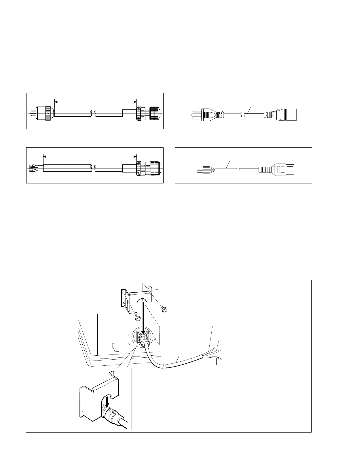
1-2-2. AC Power Cord
The PCM-3348HR includes the appropriate AC power cords for each destination of the PCM-3348HR and RM-3348HR.
PCM-3348HR
For UC
5000±100
Unit: mm
For CE
5000±100
Unit: mm
CAUTION
For PCM-3348HR CE model only
This model is High Leakage Current, be sure to connect
the wires by “Field wiring”.
This work may be regulated by laws of each country.
Follow laws of each country.
In addition, when installation, attach an AC inlet to a
bracket by fixing the screws. Refer servicing to qualified
service personal.
RM-3348HR
For UC
Power cord
For CE
Power cord
Vorsicht
Für nur PCM-3348HR CE modell
Dieses Modell ist für hohen Leckstrom ausgelegt, deshalb
immer mit “Feldverkabelung” verdrahten.
Diese Arbeit unterliegt gesetzlichen Vorschriften, die ja
nach Land unterschiedlich sein können.
Immer die örtlich geltenden Vorschriften beachten.
Außerdem muß bei ber Installation der Netzeingang mit
Schrauben an der Halterung befestigt werden.Wartung darf
nur von qualifizierten Fachpersonal ausgeführt werden.
1-2
PSW3 x 6
Bracket
Halterung
PSW3 x 6
Brown : LIVE
: STROMFÜHREND
Braun
Blue
: NEUTRAL
Blau
: NEUTRAL
Power cord
Netzkable
Green/Yellow
Grün/Geld
PCM-3348HR (supplied) / PCM-3348HR (Zubehör)
Bracket ............................1 pc. Halterung ........................ 1 Stück
Screws (PSW3 x 6) ........ 3 pcs. Schrauben (PSW3 x 6) ...3 Stücke
: GND
: GND
PCM-3348HR
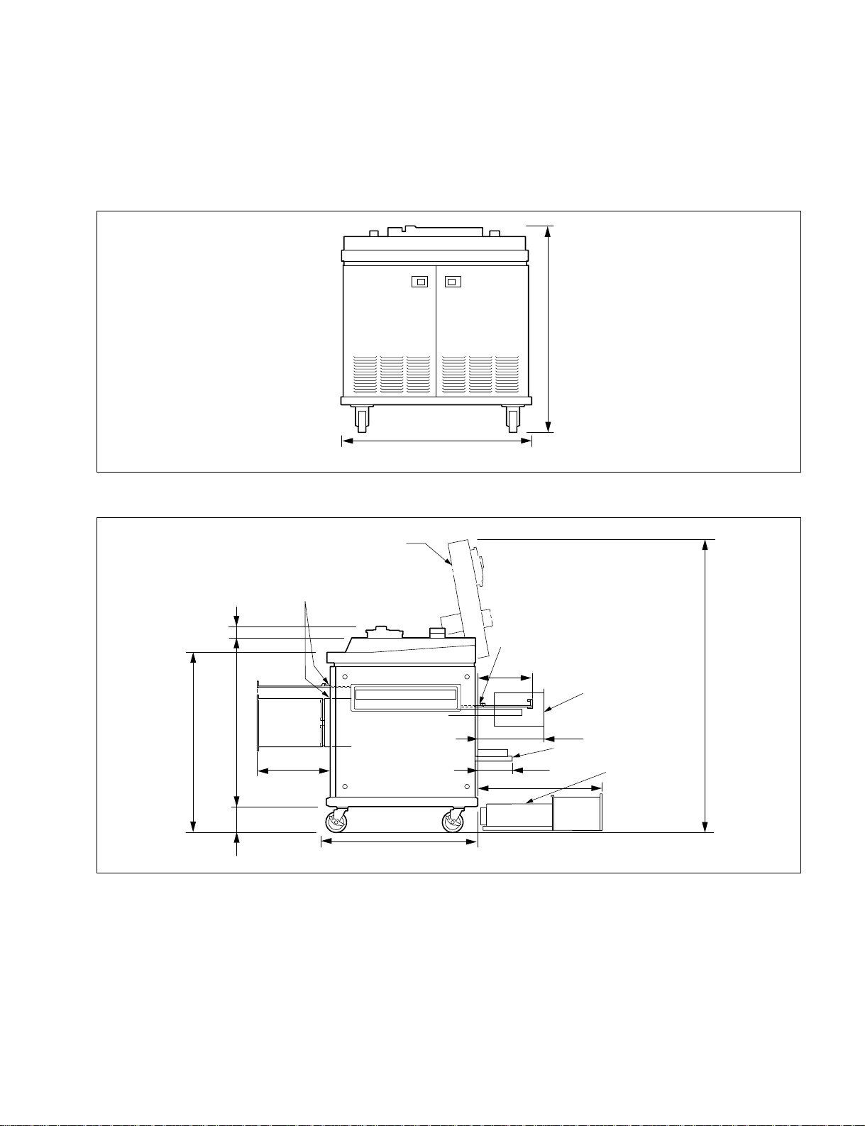
1-3. Installation Space
1-3-1. PCM-3348HR
(1) Dimensions
1-3. Installation Space
1047
(2) Working space
871
Extension board EXT-310
54
816
358
127
Mecha deck
740
916
Extention board EXT-309
269
167
610
RM/DIO
rack
323
Connector panel
Switching
regulator
Unit: mm
1420
Unit: mm
PCM-3348HR
1-3

1-3. Installation Space
1-3-2. RM-3348HR
(1) Dimensions (Remote control unit)
221266
424
490
(2) When the remote control unit is installed to the remote stand.
5°
10°
46
364
32°
20°
Unit: mm
220
150
600
1-4
526
536
Unit: mm
PCM-3348HR
 Loading...