


FM Stereo
FM/AM Receiver
4-129-743-11(1)
Operating Instructions
STR-DA1500ES
©2009 Sony Corporation
WARNING
To reduce the risk of fire or electric
shock, do not expose this apparatus to
rain or moisture.
To reduce the risk of fire, do not cover the ventilation
opening of the apparatus with newspapers,
tablecloths, curtains, etc. Do not place the naked
flame sources such as lighted candles on the
apparatus.
Do not install the appliance in a confined space, such
as a bookcase or built-in cabinet.
To reduce the risk of fire or electric shock, do not
expose this apparatus to dripping or splashing, and
do not place objects filled with liquids, such as
vases, on the apparatus.
As the main plug is used to disconnect the unit from
the mains, connect the unit to an easily accessible
AC outlet. Should you notice an abnormality in the
unit, disconnect the main plug from the AC outlet
immediately.
Do not expose batteries or apparatus with batteryinstalled to excessive heat such as sunshine, fire or
the like.
The unit is not disconnected from the mains as long
as it is connected to the AC outlet, even if the unit
itself has been turned off.
Excessive sound pressure from earphones and
headphones can cause hearing loss.
For customers in the United
States and Canada
This symbol is intended to alert
the user to the presence of the Hot
Surface that may be hot if it is
touched during the normal
operation.
ENERGY STAR
mark.
As an ENERGY STAR
Corporation has determined that this
product meets the ENERGY STAR
guidelines for energy efficiency.
®
is a U.S. registered
®
partner, Sony
®
For customers in the United
States
Owner’s Record
The model and serial numbers are located on the rear
of the unit. Record these numbers in the space
provided below. Refer to them whenever you call
upon your Sony dealer regarding this product.
Model No.
This symbol is intended to alert the
user to the presence of uninsulated
“dangerous voltage” within the
product’s enclosure that may be of
sufficient magnitude to constitute a
risk of electric shock to persons.
This symbol is intended to alert the
user to the presence of important
operating and maintenance
(servicing) instructions in the
literature accompanying the
appliance.
Serial No.
Important Safety Instructions
1) Read these instructions.
2) Keep these instructions.
3) Heed all warnings.
4) Follow all instructions.
5) Do not use this apparatus near water.
6) Clean only with dry cloth.
7) Do not block any ventilation openings. Install in
accordance with the manufacturer’s instructions.
8) Do not install near any heat sources such as
radiators, heat registers, stoves, or other
apparatus (including amplifiers) that produce
heat.
9) Do not defeat the safety purpose of the polarized
or grounding-type plug. A polarized plug has
two blades with one wider than the other. A
grounding type plug has two blades and a third
grounding prong. The wide blade or the third
prong are provided for your safety. If the
provided plug does not fit into your outlet,
consult an electrician for replacement of the
obsolete outlet.
10)Protect the power cord from being walked on or
pinched particularly at plugs, convenience
receptacles, and the point where they exit from
the apparatus.
11)Only use attachments/accessories specified by
the manufacturer.
US
2

12)Use only with the cart, stand, tripod, bracket, or
table specified by the manufacturer, or sold with
the apparatus. When a cart is used, use caution
when moving the cart/apparatus combination to
avoid injury from tip-over.
13)Unplug this apparatus during lightning storms or
when unused for long periods of time.
14)Refer all servicing to qualified service personnel.
Servicing is required when the apparatus has
been damaged in any way, such as power-supply
cord or plug is damaged, liquid has been spilled
or objects have fallen into the apparatus, the
apparatus has been exposed to rain or moisture,
does not operate normally, or has been dropped.
The following FCC statement
applies only to the version of
this model manufactured for
sale in the U.S.A. Other
versions may not comply with
FCC technical regulations.
NOTE:
This equipment has been tested and found to comply
with the limits for a Class B digital device, pursuant
to Part 15 of the FCC Rules. These limits are
designed to provide reasonable protection against
harmful interference in a residential installation.
This equipment generates, uses and can radiate radio
frequency energy and, if not installed and used in
accordance with the instructions, may cause harmful
interference to radio communications. However,
there is no guarantee that interference will not occur
in a particular installation. If this equipment does
cause harmful interference to radio or television
reception, which can be determined by turning the
equipment off and on, the user is encouraged to try
to correct the interference by one or more of the
following measures:
– Reorient or relocate the receiving antenna.
– Increase the separation between the equipment
and receiver.
– Connect the equipment into an outlet on a circuit
different from that to which the receiver is
connected.
– Consult the dealer or an experienced radio/TV
technician for help.
CAUTION
You are cautioned that any changes or modifications
not expressly approved in this manual could void
your authority to operate this equipment.
To reduce the risk of electric shock, the speaker cord
should be connected to the apparatus and the
speakers in accordance with the following
instructions.
1) Disconnect the AC power cord from the MAINS.
2) Strip 10 to 15 mm of the wire insulation of the
speaker cord.
3) Connect the speaker cord to the apparatus and
the speakers carefully so as not to touch the core
of speaker cord by hand. Also disconnect the AC
power cord from the MAINS before
disconnecting the speaker cord from the
apparatus and the speakers.
US
3
About This Manual
• The instructions in this manual are for model
STR-DA1500ES. Check your model number by
looking at the lower right corner of the front panel.
In this manual, models of area code UC is used for
illustration purposes unless stated otherwise. Any
difference in operation is clearly indicated in the
text, for example, “Models of area code UC only”.
• The instructions in this manual describe the
controls on the supplied remote. You can also use
the controls on the receiver if they have the same
or similar names as those on the remote.
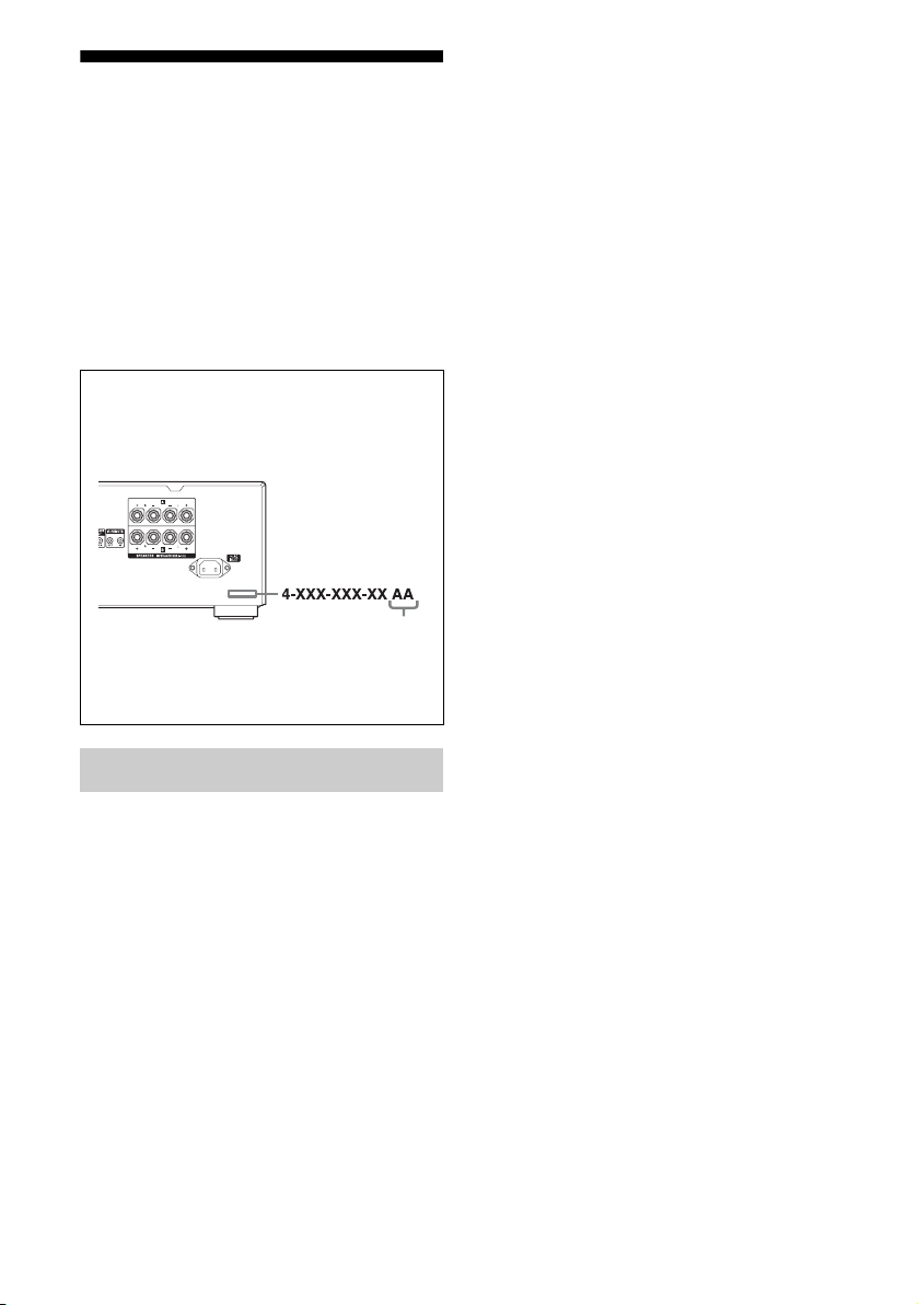
About area codes
The area code of the receiver you purchased is
shown on the lower right portion of the rear panel
(see the illustration below).
Area code
Any differences in operation, according to the area
code, are clearly indicated in the text, for example,
“Models of area code AA only”.
On Copyrights
SIRIUS, XM and all related marks and logos are
trademarks of Sirius XM Radio Inc. and its
subsidiaries. All rights reserved.
US
4

Table of Contents
Description and location of parts .................. 6
Getting Started
1: Installing the speakers............................. 13
2: Connecting the speakers ......................... 13
3a: Connecting the audio components ........ 14
3b: Connecting the video components........ 15
4: Connecting the antennas (aerials) ........... 19
5: Preparing the receiver and the remote..... 19
6: Selecting the speaker system .................. 21
Playback
Enjoying sound/images from the component
connected to the receiver........................ 22
Amplifier Operations
Navigating through menus.......................... 24
Adjusting the level (LEVEL menu) ............ 26
Adjusting the equalizer (EQ menu) ............ 26
Settings for the tuner (TUNER menu)........ 27
Settings for the system (SYSTEM menu)... 28
Using the Remote
Changing button assignments...................... 51
Additional Information
Precautions .................................................. 52
Troubleshooting...........................................53
Specifications .............................................. 56
Index............................................................ 58
Tuner Operations
Listening to FM/AM radio.......................... 29
Presetting radio stations .............................. 31
Listening to Satellite Radio......................... 33
Connecting a satellite radio tuner................ 34
Preparing to listen to a satellite radio.......... 34
Selecting a channel of the satellite radio..... 37
Presetting satellite radio channels............... 38
Restricting access to specific channels
(Parental Lock) (SIRIUS only) .............. 40
Other Operations
Enjoying the DIGITAL MEDIA PORT
(DMPORT) ............................................ 44
Changing the display................................... 46
Using the Sleep Timer................................. 47
Recording using the receiver....................... 47
Using multi-zone features ........................... 48
US
5
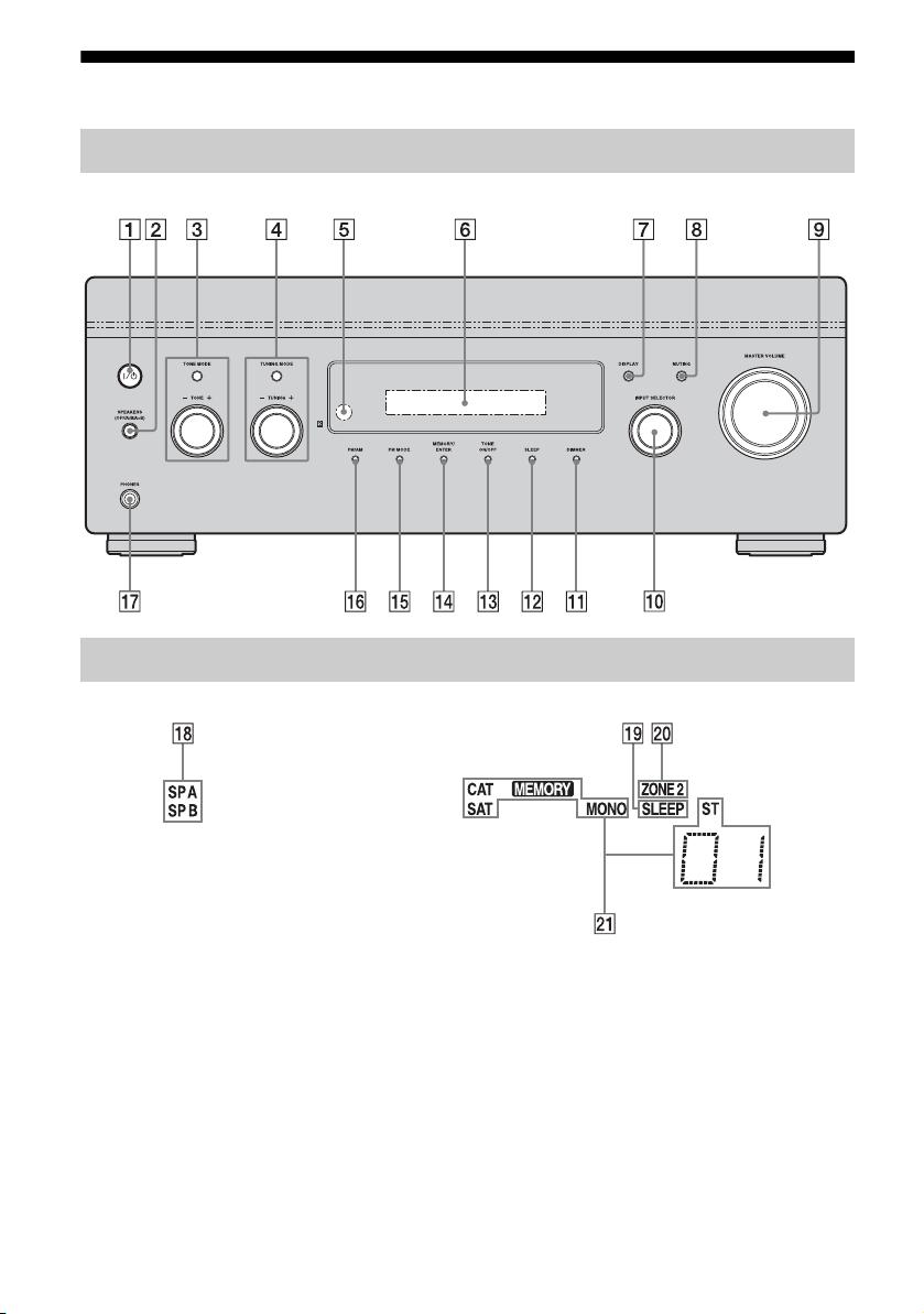
Description and location of parts
Front panel
About the indicators on the display
US
6
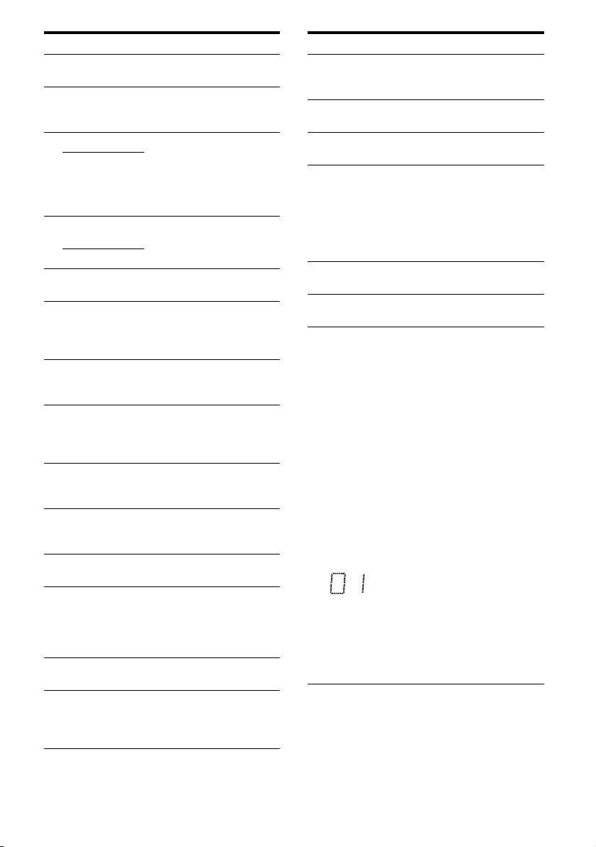
Name Function
A ?/1
(on/standby)
B SPEAKERS
(OFF/A/B/
A+B)
C TONE MODE Adjust the bass and treble
TONE +/ –
D TUNING
MODE
TUNING +/–
E Remote
sensor
F Display
window
G DISPLAY Press repeatedly to select
H MUTING Press to turn off the sound
I MASTER
VOLUM E
J INPUT
SELECTOR
K DIMMER Press repeatedly to adjust the
L SLEEP Press to activate the sleep
M TONE ON/OFF Press to turn the bass and
N MEMORY/
ENTER
Press to turn the receiver on
or off (page 20, 30).
Switch to OFF, A, B, A+B of
the front speakers (page 21).
level of the speakers. Press
TONE MODE repeatedly to
select bass or treble, then turn
TONE +/– to adjust the level
(page 25).
Press to operate a tuner (FM/
AM) and satellite radio (XM/
SIRIUS) (page 29, 36, 37).
Receives signals from remote
commander.
The current status of the
selected component or a list
of selectable items appears
here (page 6).
information displayed on the
display (page 46).
temporarily.
Press MUTING again to
restore the sound (page 23).
Turn to adjust the volume
level of all speakers at the
same time (page 22).
Turn to select the input
source to play back (page 22,
23, 46, 47, 48).
brightness of the display.
timer function and the
duration which the receiver
turns off automatically (page
47).
treble on or off.
Press to store a station or
enter the selection when
selecting the settings (page
20, 31, 39).
Name Function
O FM MODE Press to select the FM
P FM/AM Press to select FM or AM
Q PHONES jack Connects to headphones
R SP A/SP B Lights up according to the
S SLEEP Lights up when the sleep
T ZONE 2 Lights up when operation in
U Tuning
indicators
CAT Lights up when the category
SAT Lights up when the satellite
MEMORY Lights up when a memory
MONO Monaural broadcast
ST Stereo broadcast
monaural or stereo reception
(page 29).
station.
(page 53).
speaker system used (page
21). However, these
indicators do not light up if
the speaker output is turned
off or if headphones are
connected.
timer is activated.
zone 2 is being enabled.
Lights up when the receiver
tunes in radio stations, or
satellite radio stations.
mode is set to “ONE CAT”
during the satellite radio
operation.
radio is connected and “XM
RADIO” or “SIRIUS” is
selected.
function, such as Preset
Memory (page 31), etc., is
activated.
A preset station number
appears when the preset radio
station is selected.
Note
The preset station number
will change accordingly to
the preset station you select.
For details on presetting
radio station, see page 31.
US
7
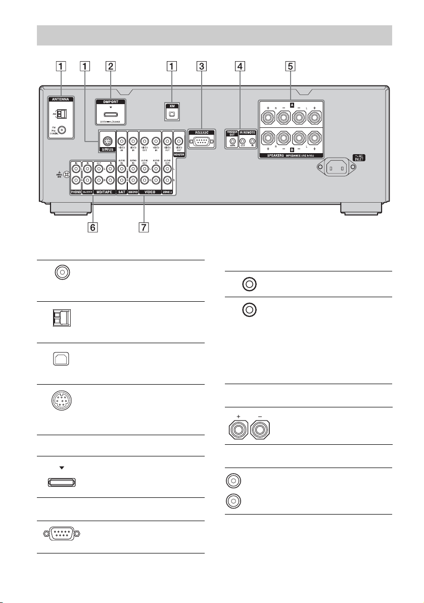
Rear panel
A ANTENNA section
FM
ANTENNA
jack
AM
ANTENNA
jack
XM jack Connects to the XM
SIRIUS jack Connects to a
B DMPORT
DMPORT
jack
C RS232C port
Connects to the
supplied FM wire
antenna (aerial)
(page 19).
Connects to the
supplied AM loop
antenna (aerial)
(page 19).
Mini-Tuner and
Home Dock (not
supplied) (page 34).
SiriusConnect
Home tuner (not
supplied)
(page 34).
Connects to a
DIGITAL MEDIA
PORT adapter
(page 45).
Used for
maintenance and
service.
D Control jacks for Sony equipment
and other external components
IR REMOTE
IN/OUT jacks
TRIGGER
OUT jack
Connect an IR
repeater (page 48).
Connects to an
interlock on/off of
the power supply of
other 12V
TRIGGER
compliant
components, or the
amplifier/receiver
of zone 2 (page 28).
E SPEAKERS section
Connects to the
speakers (page 13).
F AUDIO INPUT/OUTPUT section
White (L)
Red (R)
AUDIO IN/
OUT jacks
Connects to a tape
deck or MD deck,
etc. (page 14).
US
8
G VIDEO/AUDIO INPUT/OUTPUT
section
White (L)
Red (R)
Yellow
* You can watch the selected input image when you
connect the MONITOR OUT jack to a TV (page
16–18).
AUDIO IN/
OUT jacks
VIDEO IN/
OUT* jacks
AUDIO OUT
jacks
VIDEO OUT
jack
Connects to a VCR,
DVD player, etc.
(page 16–18).
Connects to the
component in zone
2 (page 49).
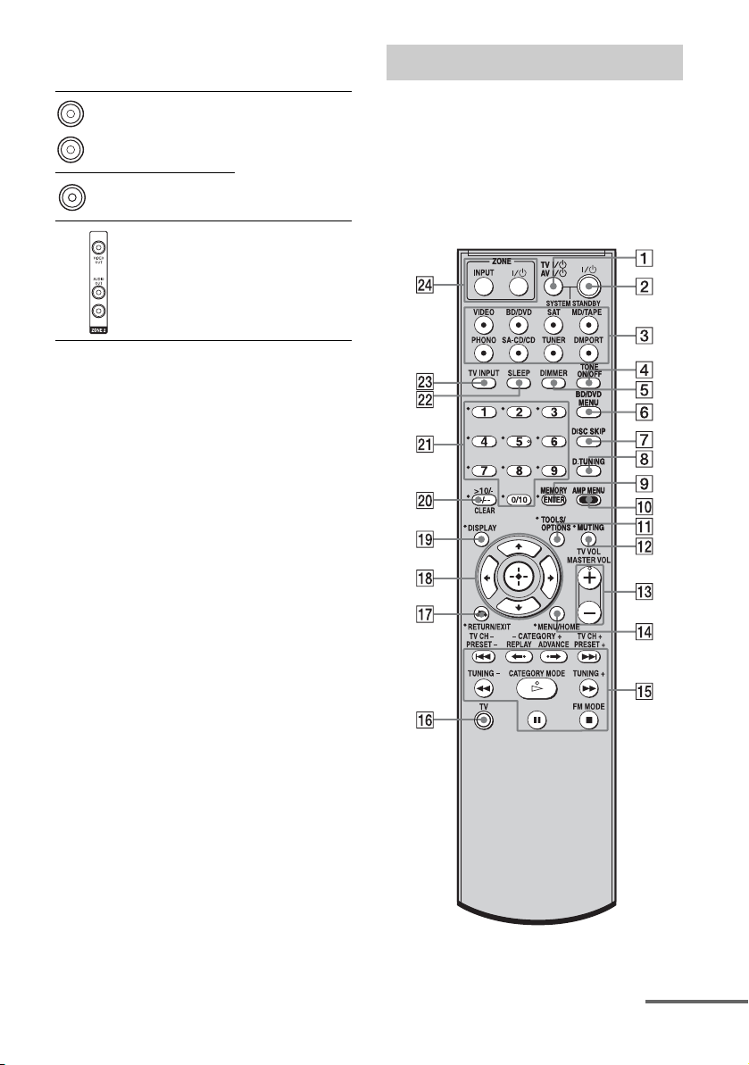
Remote commander
You can use the supplied RM-AAU056
Remote Commander to operate the receiver
and to control the Sony audio/video
components that the remote is assigned to
operate (page 51).
RM-AAU056
continued
US
9

Name Function
A TV ?/1
(on/standby)
AV ?/1
(on/standby)
B ?/1
(on/standby)
C Input buttons Press one of the buttons to
D TONE ON/OFF Press to turn the bass and
E DIMMER Press repeatedly to adjust the
Press TV ?/1 and TV (P) at
the same time to turn the TV
on or off.
Press to turn on or off the
Sony audio/video components
that the remote is assigned to
operate (page 51).
If you press ?/1 (B) at the
same time, it will turn off the
receiver and other Sony
components (SYSTEM
STANDBY).
Note
The function of the AV ?/1
switch changes automatically
each time you press the input
buttons (C).
Press to turn the receiver on or
off.
If zone 2 is selected, only the
main receiver is turned on or
off with this button. To turn
off all components including
an amplifier in zone 2, press
?/1 and AV ?/1 (A) at the
same time (SYSTEM
STANDBY).
Saving the power in standby
mode.
When “RS232C” (page 28) is
set to “OFF”.
select the component you
want to use. When you press
any of the input buttons, the
receiver turns on. The buttons
are factory assigned to control
Sony components.
You can change the button
assignments following the
steps in “Changing button
assignments” on page 51.
treble on or off.
brightness of the display.
Name Function
F BD/DVD
MENU
G DISC SKIP Press to skip a disc when
H D.TUNING Press to enter direct tuning
I ENTER Press to enter the value after
MEMORY Press to store a station during
J AMP MENU Press to display the menu of
K TOOLS/
OPTIONS
L MUTING Press to turn off the sound
M TV VOL
a)
+
/–
MASTER
a)
VOL +
N MENU/HOME Press to display the menu of
Press to display the menu of
the DVD or Blu-ray disc on
the TV screen. Then, use V, v,
B, b and (qk) to perform
menu operations.
using a multi-disc changer.
mode.
selecting a channel, disc or
track using the numeric
buttons of the TV, VCR, CD
player, DVD player, DVD
recorder or satellite tuner.
tuner operation.
the receiver. Then, use V, v,
B, b and (qk) to perform
menu operations.
Press to display and select the
options of the DVD player or
Blu-ray disc player.
Press TOOLS/OPTIONS and
TV (P) at the same time to
display the options applicable
to the Sony TV.
temporarily.
Press MUTING again to
restore the sound.
Press MUTING and TV (P)
at the same time to activate
the TV’s muting function.
Press TV VOL +/– and TV
(P) at the same time to adjust
the volume level of the TV.
Press to adjust the volume
/–
level of all speakers at the
same time.
the VCR, DVD player,
satellite tuner or Blu-ray disc
player on the TV screen.
Press MENU/HOME and TV
(P) at the same time to
display the TV’s menu.
Then, use V, v, B, b and
(qk) to perform menu
operations.
10
US
Name Function
O ./>
REPLAY /
ADVANCE
m/M
H
X
x
TV CH +/– Press TV CH +/– and TV (P)
CATEGORY
+/–
PRESET +/– Press to select
TUNING +/– Press to scan a station.
CATEGORY
MODE
FM MODE Press to select the FM
b)
Press to skip a track of the CD
player, DVD player, DVD
recorder, MD deck, tape deck
or Blu-ray disc player.
<
Press to replay the previous
<
scene or fast forward the
current scene of the VCR,
DVD player or Blu-ray disc
player.
b)
Press to
– search tracks in the forward/
reverse direction of the
DVD player.
– start fast forward/rewind of
the VCR, CD player, DVD
recorder, MD deck, tape
deck or Blu-ray disc player.
a)b)
Press to start playback of the
VCR, CD player, DVD
player, DVD recorder, MD
deck or Blu-ray disc player.
b)
Press to pause playback or
recording of the VCR, CD
player, DVD player, DVD
recorder, MD deck, tape deck
or Blu-ray disc player. (Also
starts recording with
components in recording
standby.)
b)
Press to stop playback of the
VCR, CD player, DVD
player, DVD recorder, MD
deck, tape deck or Blu-ray
disc player.
at the same time to select
preset TV channels.
Press to select a category for
satellite tuner (page 37).
– preset stations.
– preset channels of the VCR
or satellite tuner.
Press to select the category
mode for satellite tuner (page
37).
monaural or stereo reception.
Name Function
P TV Press TV and the button with
Q RETURN/
EXIT O
R
V/v/B/b
S DISPLAY Press to select information
orange printing at the same
time to enable TV operation.
Press to
– return to the previous menu.
– exit the menu while the
menu or on-screen guide of
the DVD recorder, DVD
player, satellite tuner or Bluray disc player is displayed
on the TV screen.
Press RETURN/EXIT O
and TV (P) at the same time
to return to the previous menu
or exit the TV’s menu while
the menu is displayed on the
TV screen.
After pressing BD/DVD
MENU (F), AMP MENU
(0), or MENU/HOME (N),
press V, v, B or b to select the
settings. Then, press to
enter the selection if you have
pressed BD/DVD MENU or
MENU/HOME previously.
Press also to enter the
selection of the receiver,
VCR, satellite tuner, CD
player, DVD player, DVD
recorder or Blu-ray disc
player.
displayed on the TV screen of
the VCR, satellite tuner, CD
player, DVD player, DVD
recorder, MD deck or Blu-ray
disc player.
Press DISPLAY and TV (P)
at the same time to display
TV’s information on the TV
screen.
continued
11
US

Name Function
T -/-- Press to select the channel
>10/
-
CLEAR Press to clear a mistake when
U Numeric
buttons
(number 5
V SLEEP Press to activate the Sleep
W TV INPUT Press TV INPUT and TV (P)
X ZONE ?/1 Press ZONE ?/1 to turn the
ZONE INPUT Press ZONE INPUT
entry mode, either one or two
digit of the VCR, satellite
tuner, etc.
Press -/-- and TV (P) at the
same time to select the
channel entry mode, either
one or two digits of the TV.
Press to select
– track numbers over 10 of the
VCR, satellite tuner, MD
deck or CD player.
– channel numbers of the
Digital CATV terminal.
you press the incorrect
numeric button.
Press to
– preset/tune to preset
a)
)
stations.
– select track numbers of the
CD player, DVD player,
DVD recorder, MD deck or
Blu-ray disc player. Press
0/10 to select track number
10.
– select channel numbers of
the VCR or satellite tuner.
Press the numeric buttons and
TV (P) at the same time to
select the TV channels.
Timer function and the
duration which the receiver
turns off automatically.
at the same time to select the
input signal (TV input or
video input).
zone 2 on or off.
repeatedly to select the input
source for zone 2.
a)
The number 5, MASTER VOL +, TV VOL +, and
H buttons have tactile dots. Use the tactile dots
as references when operating the receiver.
b)
This button is also available for DIGITAL MEDIA
PORT adapter operation. For details on the
function of the button, refer to the operating
instructions supplied with the DIGITAL MEDIA
PORT adapter.
Notes
• Some functions explained in this section may not
work depending on the model.
• The above explanation is intended to serve as an
example only. Therefore, depending on the
component, the above operation may not be
possible or may operate differently than described.
12
US
Getting Started
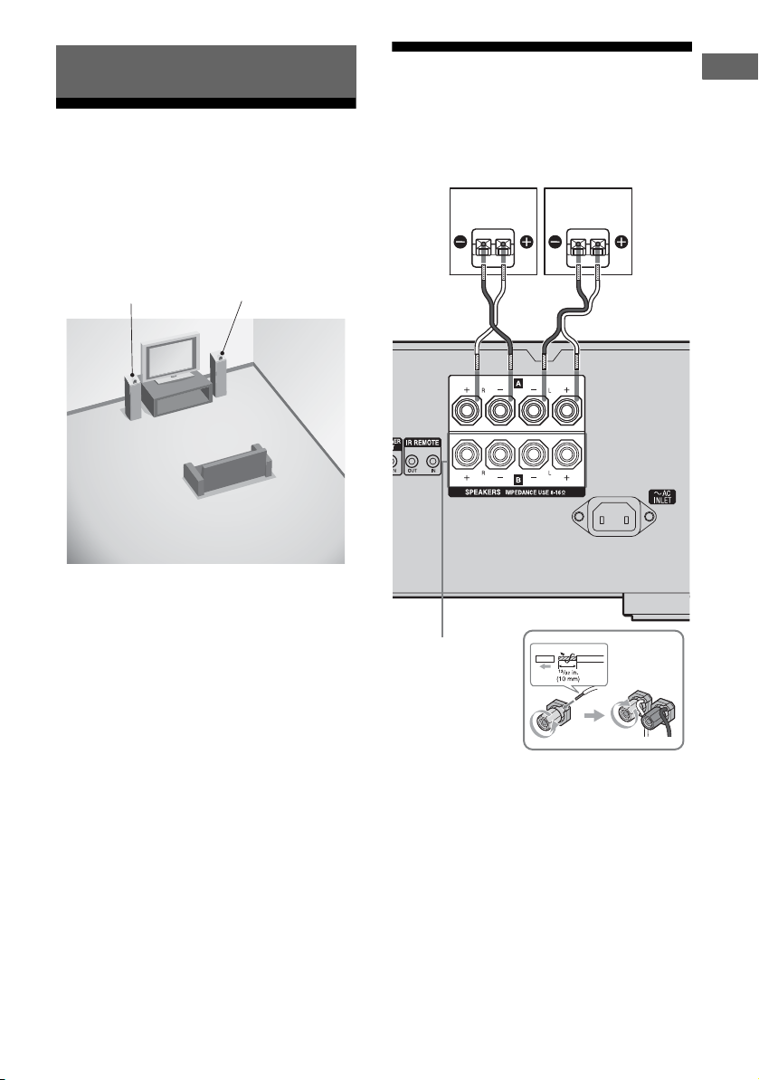
1: Installing the speakers
This receiver allows you to use a 2.0 channel
system.
Example of the speaker system
configuration
Right speakerLeft speaker
2: Connecting the speakers
Before connecting the cords, be sure to
disconnect the AC power cord (mains lead).
Left speakerRight speaker
A
Getting Started
SPEAKERS B
terminals*
A Speaker cords (not supplied)
*
If you have an additional front speaker system,
connect them to the SPEAKERS B terminals.
You can select the front speakers you want to use
with SPEAKERS (OFF/A/B/A+B) on the front
panel (page 21).
13
US
.
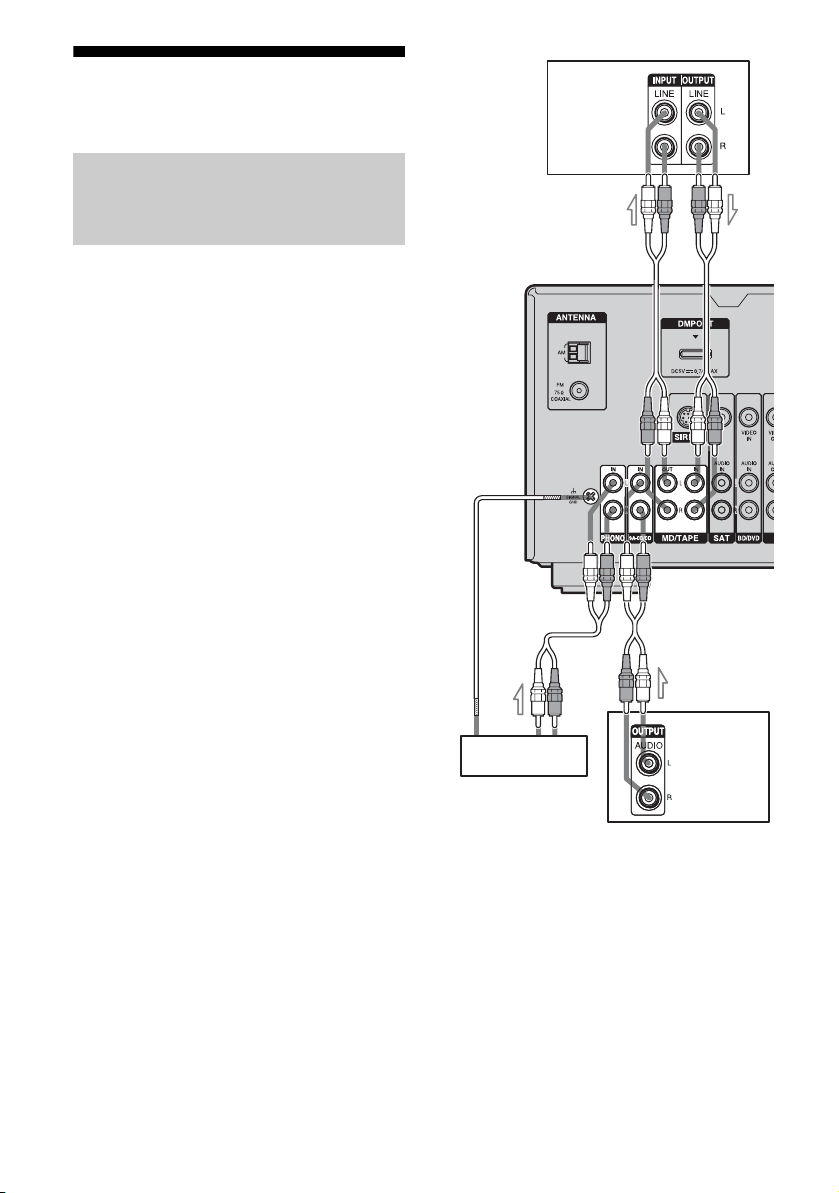
3a: Connecting the audio components
Connecting a Super Audio CD
player, CD player, MD deck,
Tape deck or Turntable
The following illustration shows how to
connect a Super Audio CD player, CD player,
MD deck, tape deck or turntable.
Before connecting the cords, be sure to
disconnect the AC power cord (mains lead).
After connecting your audio component,
proceed to “3b: Connecting the video
components”(page 15).
MD deck,
Tape deck
A
A
14
Super Audio
Turntable
CD player,
CD player
A Audio cord (not supplied)
Note
If your turntable has a ground (earth) wire, connect
it to the (U) SIGNAL GND terminal.
US

3b: Connecting the video components
How to connect your
components
This section describes how to connect your
video components to this receiver. Before you
begin, refer to “Component to be connected”
below for the pages which describe how to
connect each component.
Before connecting the cords, be sure to
disconnect the AC power cord (mains lead).
After connecting all your components,
proceed to “4: Connecting the antennas
(aerials)” (page 19).
Component to be connected Page
Blu-ray disc player, DVD player 16
Satellite tuner, Set-top box 17
DVD recorder, VCR 18
Getting Started
15
US

Connecting a Blu-ray disc
player, DVD player
The following illustration shows how to
connect a Blu-ray disc player or a DVD player.
Connect audio and video cords according to
the jacks of your components.
If you connect a DVD player
• Be sure to change the factory setting of the
BD/DVD input button on the remote so that
you can use the button to control your DVD
player. For details, see “Changing button
assignments” (page 51).
• You can also rename the BD/DVD input so
that it can be displayed on the receiver’s
display. For details, see “Naming inputs”
(page 23).
Blu-ray disc player, DVD player
Audio signals Video signals
AB
TV
Video signals
B
A Audio cord (not supplied)
B Video cord (not supplied)
US
16
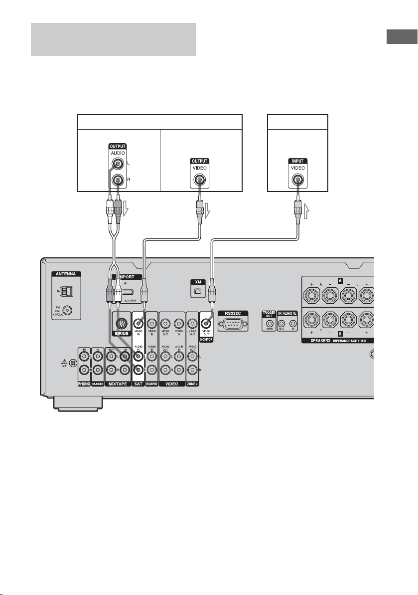
Connecting a satellite tuner,
Set-top box
The following illustration shows how to
connect a satellite tuner or a Set-top box.
Connect audio and video cords according to
the jacks of your components.
Getting Started
Satellite tuner, Set-top box
Audio signals Video signals
AB
TV
Video signals
B
A Audio cord (not supplied)
B Video cord (not supplied)
17
US
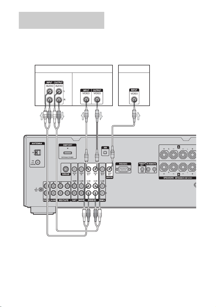
Connecting components with
analog video and audio jack
The following illustration shows how to
connect a component which has analog jacks
such as a DVD recorder, VCR, etc.
Connect audio and video cords according to
the jacks of your components.
DVD recorder, VCR
Video signals Audio signals
A
B
TV
Video signals
B
A Audio cord (not supplied)
B Video cord (not supplied)
Notes
• Be sure to change the factory setting of the
VIDEO input button on the remote so that you can
use the button to control your DVD recorder. For
details, see “Changing button assignments” (page
51).
US
18
• You can also rename the VIDEO input so that it
can be displayed on the receiver’s display. For
details, see “Naming inputs” (page 23).