

Sony Xperia Z3, D6603, D6653, D6643, D6616 Working Instructions
Working Instructions
- mechanical -
Xperia
D6603,D6616,D6643,D6653
1288-9438 Rev 2
© Sony Mobile Communications AB – Company Internal
TM
Z3

Working Instructions (mech)
CONTENTS
1 Exterior Views ................................................................................. 6
1.1 D6603, D6616, D6643, D6653 ................................................................ 6
2 Tools ................................................................................................ 7
3 Disassembly.................................................................................... 9
3.1 Sim Tray ................................................................................................. 9
3.2 Rear Panel ............................................................................................ 10
3.3 Sub Antenna ........................................................................................ 11
3.4 Holder Main Camera ............................................................................ 12
3.5 Main Camera ........................................................................................ 12
3.6 Antenna BT + WLAN ........................................................................... 13
3.7 Main PBA .............................................................................................. 13
3.8 Shield Main Camera ............................................................................ 15
3.9 Audio Jack ........................................................................................... 15
3.10 RF cable ............................................................................................... 16
3.11 Embedded Battery ............................................................................... 16
3.12 Cushion Battery ................................................................................... 16
3.13 Main Antenna ....................................................................................... 17
3.14 Holder Vibrator .................................................................................... 18
3.15 Plate Speaker ....................................................................................... 19
3.16 Holder Speaker sub assembly ........................................................... 19
3.17 Charge FPC .......................................................................................... 20
3.18 Holder key volume .............................................................................. 21
3.19 Plate holder speaker ........................................................................... 22
3.20 Relay FPC + Front Assy ...................................................................... 22
4 Replacement ................................................................................. 23
4.1 Sim Tray ............................................................................................... 23
4.2 Rear Panel ............................................................................................ 23
4.3 Sub Antenna ........................................................................................ 23
4.4 Holder Main Camera ............................................................................ 23
4.5 Main Camera ........................................................................................ 24
4.6 Antenna BT + WLAN ........................................................................... 24
4.7 Main PBA .............................................................................................. 24
4.8 Shield Main Camera ............................................................................ 24
4.9 Audio Jack ........................................................................................... 25
4.10 RF cable ............................................................................................... 25
4.11 Embedded Battery ............................................................................... 25
4.12 Cushion Battery ................................................................................... 25
4.13 Main Antenna ....................................................................................... 26
4.14 Holder Vibrator .................................................................................... 26
1288-9438 Rev 2
© Sony Mobile Communications AB – Company Internal 2(97)

Working Instructions (mech)
4.15 Plate Speaker ....................................................................................... 26
4.16 Holder Speaker sub assembly ........................................................... 26
4.17 Charge FPC .......................................................................................... 27
4.18 Holder key volume .............................................................................. 27
4.19 Plate holder speaker ........................................................................... 27
4.20 Relay FPC ............................................................................................. 27
4.21 Front Assy ............................................................................................ 28
4.22 Adhesive Battery Front ....................................................................... 29
4.23 Adhesive Battery Rear ........................................................................ 30
4.24 Adhesive Battery Rear 2 ..................................................................... 31
4.25 Adhesive Charger FPC ....................................................................... 32
4.26 Adhesive FPC Speaker ....................................................................... 33
4.27 Adhesive Rear Panel ........................................................................... 34
4.28 Adhesive Relay FPC A ........................................................................ 35
4.29 Adhesive Relay FPC B ........................................................................ 36
4.30 Adhesive WP Audio Jack ................................................................... 37
4.31 Adhesive WP holder speaker ............................................................. 38
4.32 Adhesive WP Speaker ......................................................................... 39
4.33 Cap SD .................................................................................................. 40
4.34 Cap USB ............................................................................................... 41
4.35 Core Unit Label .................................................................................... 42
4.36 Cushion Audio Jack FPC BtB ............................................................ 43
4.37 Cushion Battery FPC BtB ................................................................... 44
4.38 Cushion Camera BtB .......................................................................... 45
4.39 Cushion Chat Camera ......................................................................... 46
4.40 Cushion Rear Panel ............................................................................ 47
4.41 Cushion Relay FPC bottom BtB ......................................................... 48
4.42 Cushion Relay FPC BtB ...................................................................... 49
4.43 Cushion Speaker ................................................................................. 50
4.44 Cushion Vibrator ................................................................................. 51
4.45 Gasket conductive USB ...................................................................... 52
4.46 Gore Sheet(1st mic) .............................................................................. 53
4.47 Grill Receiver ....................................................................................... 54
4.48 Holder Mic sub assembly ................................................................... 55
4.49 Holder Receiver sub assembly .......................................................... 56
4.50 Label Plate ........................................................................................... 57
4.51 Label Plate Guide ................................................................................ 58
4.52 Lightguide 3 LED ................................................................................. 59
4.53 Liquid Indicator ................................................................................... 60
4.54 Loudspeaker ........................................................................................ 61
4.55 Loudspeaker B .................................................................................... 62
1288-9438 Rev 2
© Sony Mobile Communications AB – Company Internal 3(97)

Working Instructions (mech)
4.56 Magnetic connector ............................................................................ 63
4.57 Sheet ACO L ........................................................................................ 64
4.58 Sheet ACO R ........................................................................................ 65
4.59 Sheet Battery Rear .............................................................................. 66
4.60 Sheet Chat Camera ............................................................................. 67
4.61 Sheet copper display BtB ................................................................... 68
4.62 Sheet Relay FPC .................................................................................. 69
4.63 Sheet Sub Antenna ............................................................................. 70
4.64 Sheet Sub PBA A ................................................................................. 71
4.65 Sheet thermal MSM ............................................................................. 72
4.66 Sheet touch FPC CN ........................................................................... 73
4.67 Spacer Sub Antenna ........................................................................... 74
4.68 Sub Camera ......................................................................................... 75
4.69 Sub PBA-A ........................................................................................... 76
4.70 Sub PBA-B ........................................................................................... 77
4.71 Water Indicator .................................................................................... 78
4.72 Board Swap - Replacement ................................................................ 79
4.73 Board Swap – Change Label .............................................................. 80
4.74 Board Swap – Customize of Software ............................................... 80
5 Reassembly................................................................................... 81
5.1 Front assy & Relay FPC ...................................................................... 81
5.2 Plate Holder Speaker .......................................................................... 81
5.3 Holder key volume .............................................................................. 82
5.4 Charge FPC .......................................................................................... 83
5.5 Holder Speaker sub assembly ........................................................... 84
5.6 Plate Speaker ....................................................................................... 85
5.7 Holder Vibrator .................................................................................... 85
5.8 Main Antenna ....................................................................................... 86
5.9 Cushion Battery ................................................................................... 87
5.10 Embedded Battery ............................................................................... 87
5.11 RF cable ............................................................................................... 88
5.12 Audio Jack ........................................................................................... 89
5.13 Shield Main Camera ............................................................................ 90
5.14 Main PBA .............................................................................................. 90
5.15 Antenna BT + WLAN ........................................................................... 91
5.16 Main Camera ........................................................................................ 92
5.17 Holder Main Camera ............................................................................ 92
5.18 Sub Antenna ........................................................................................ 93
5.19 Rear Panel ............................................................................................ 93
5.20 Sim Tray ............................................................................................... 95
1288-9438 Rev 2
© Sony Mobile Communications AB – Company Internal 4(97)

Working Instructions (mech)
6 Revision History ........................................................................... 97
For general information about mechanical repair related issues, refer to
1220-1333: Generic Repair Manual - mechanical
1288-9438 Rev 2
© Sony Mobile Communications AB – Company Internal 5(97)
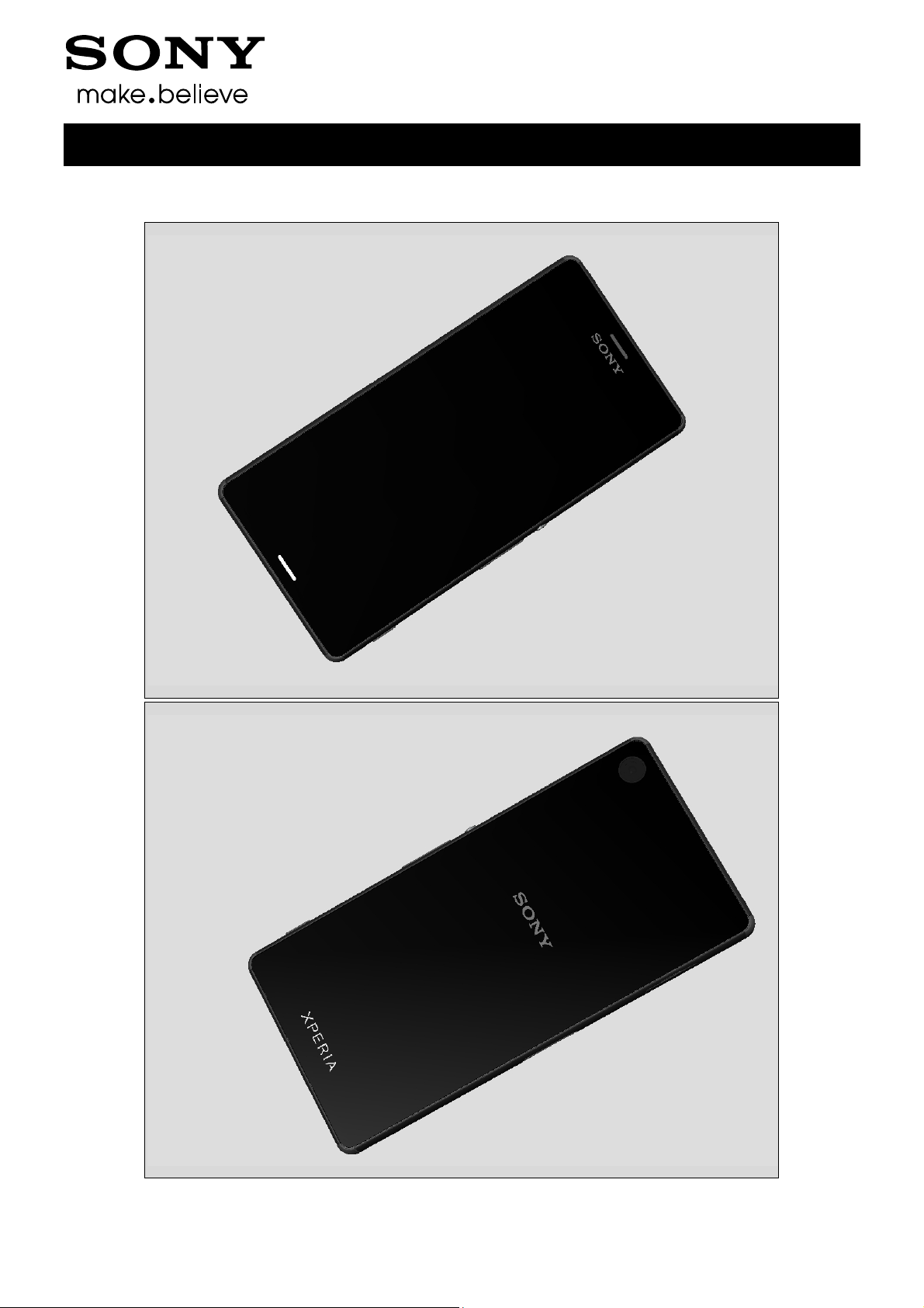
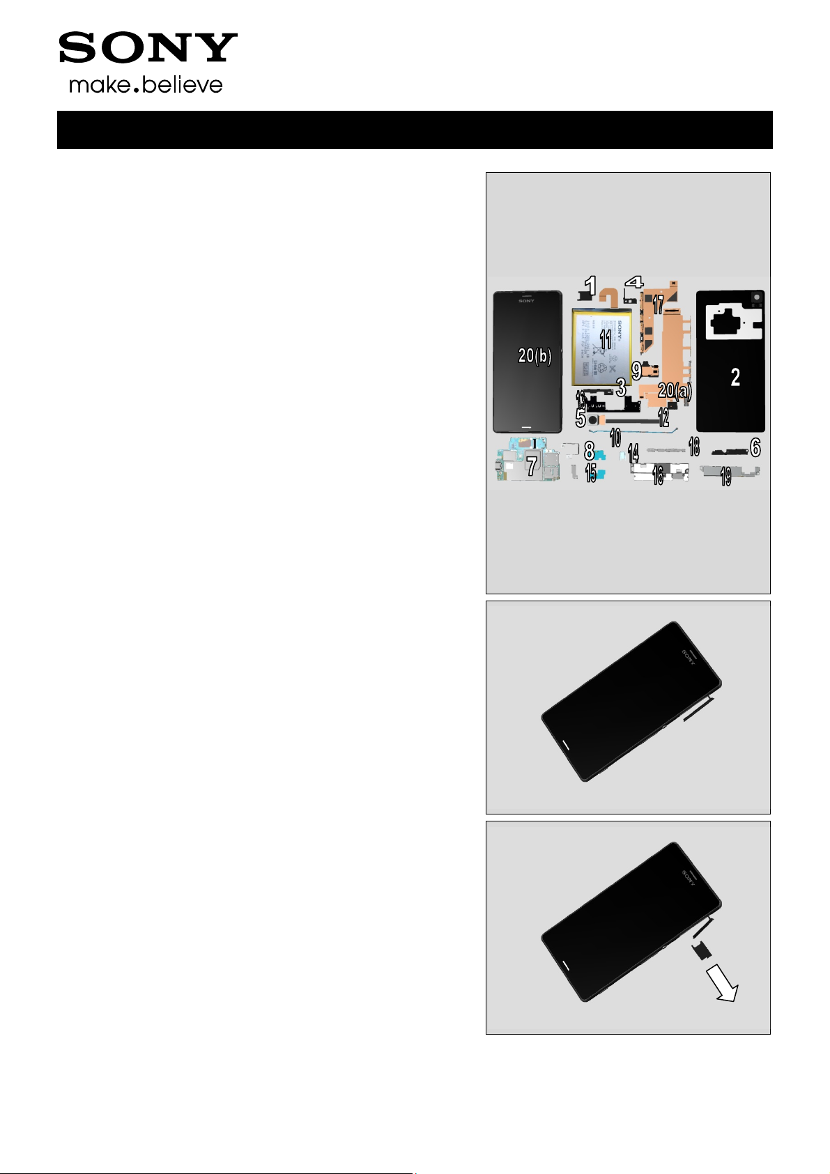
1 Exterior Views
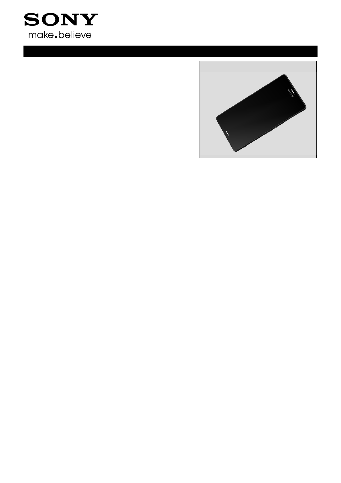
1.1 D6603, D6616, D6643, D6653
Working Instructions (mech)
1288-9438 Rev 2
© Sony Mobile Communications AB – Company Internal 6(97)
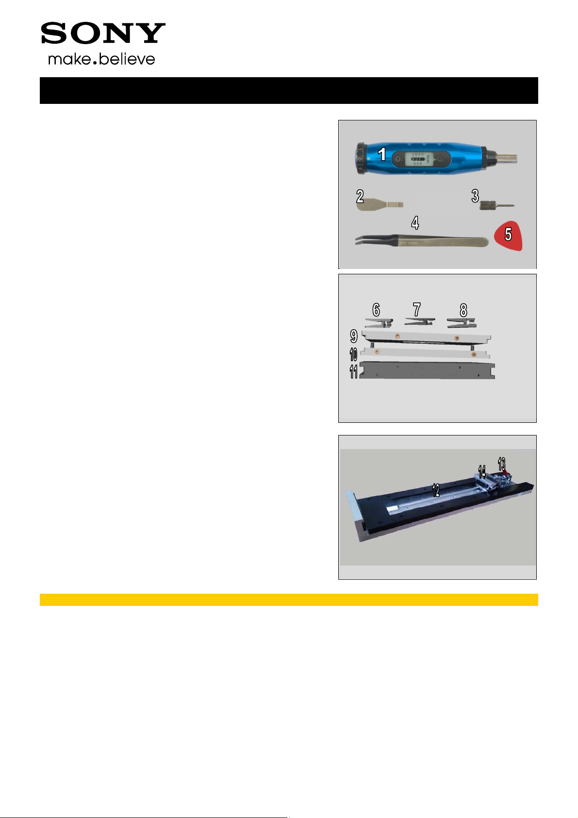
2 Tools
SPECIAL TOOLS
1. Torque Screwdriver
2. Front Opening Tool
3. Bits (JCIS No 0)
4. Flex Film Assembly Tool
5. Guitar Pick
6. Audio Jack Press
7. Press Tool Loudspeaker
8. Speaker FPC Press
9. Rear Panel Press Top Inlay
10. Bottom Press Inlay
11. Rear Panel Adhesive alignment fixture
Working Instructions (mech)
12. Side Panel press
13. Side Panel Press Head
14. Charge connector press pad
For part no’s on the tools above, refer to the ‘Tools Catalogue/Matrix’.
1288-9438 Rev 2
© Sony Mobile Communications AB – Company Internal 7(97)
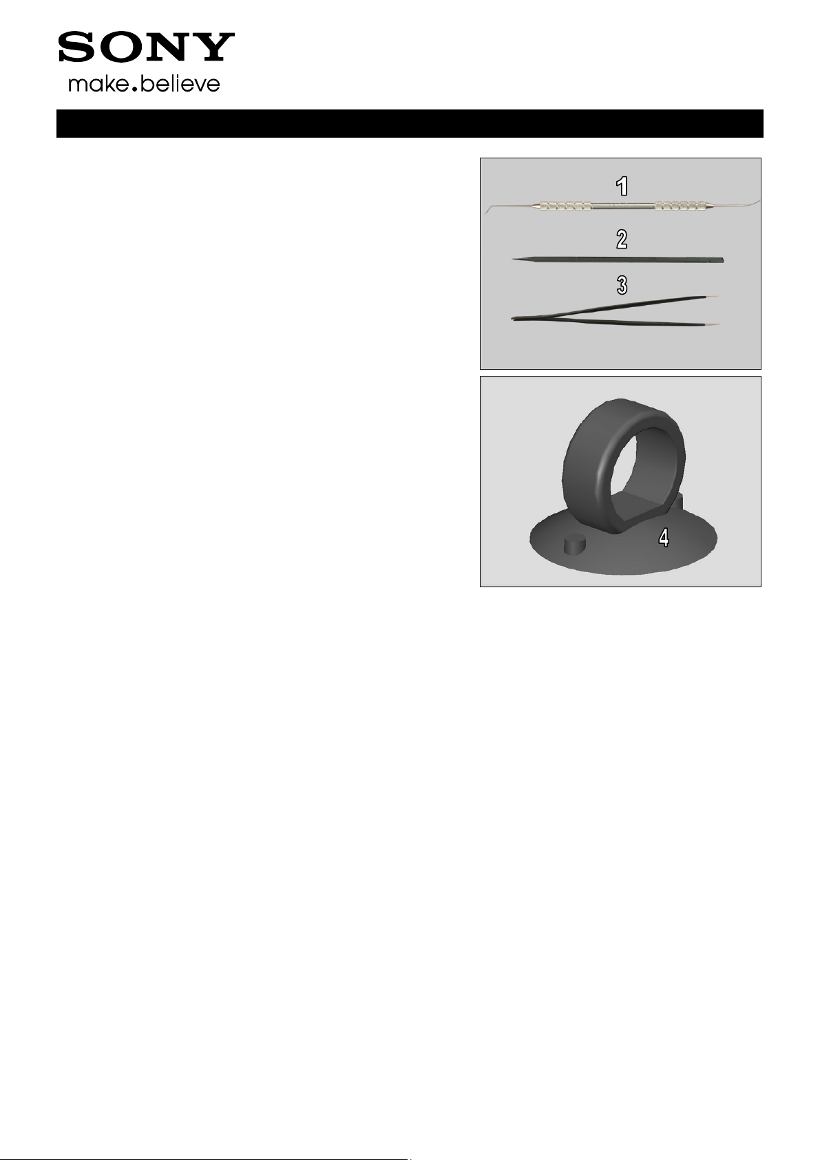
Tools
STANDARD TOOLS
1. Dentist Hook
2. Nylon Pointer
3. Tweezers
4. Suction Cup
Working Instructions (mech)
1288-9438 Rev 2
© Sony Mobile Communications AB – Company Internal 8(97)
3 Disassembly
The disassembly is done in the following order:
1. Sim Tray
2. Rear Panel
3. Sub Antenna
4. Holder Main Camera
5. Main Camera
6. Antenna BT + WLAN
7. Main PBA
8. Shield Main Camera
9. Audio Jack
10. RF cable
11. Embedded Battery
12. Cushion Battery
13. Main Antenna
14. Holder Vibrator
15.Plate Speaker
16. Holder Speaker sub assembly
17. Charge FPC
18. Holder key volume
19. Plate Holder Speaker
20. Relay FPC (a) + Front Assy (b)
Working Instructions (mech)
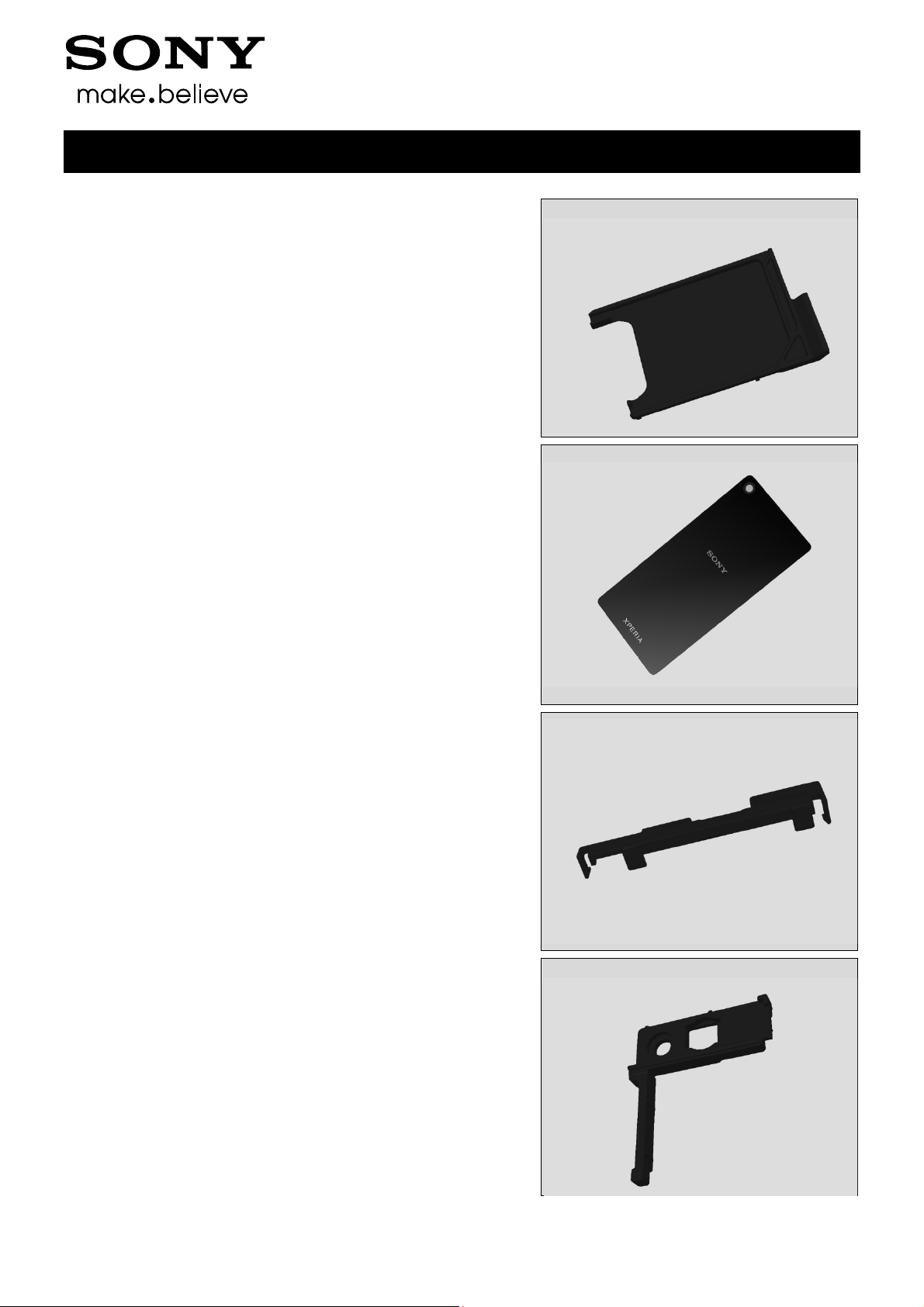
3.1 Sim Tray
Open the Cap SD
Remove the Sim Tray with fingers
1288-9438 Rev 2
© Sony Mobile Communications AB – Company Internal 9(97)
Disassembly
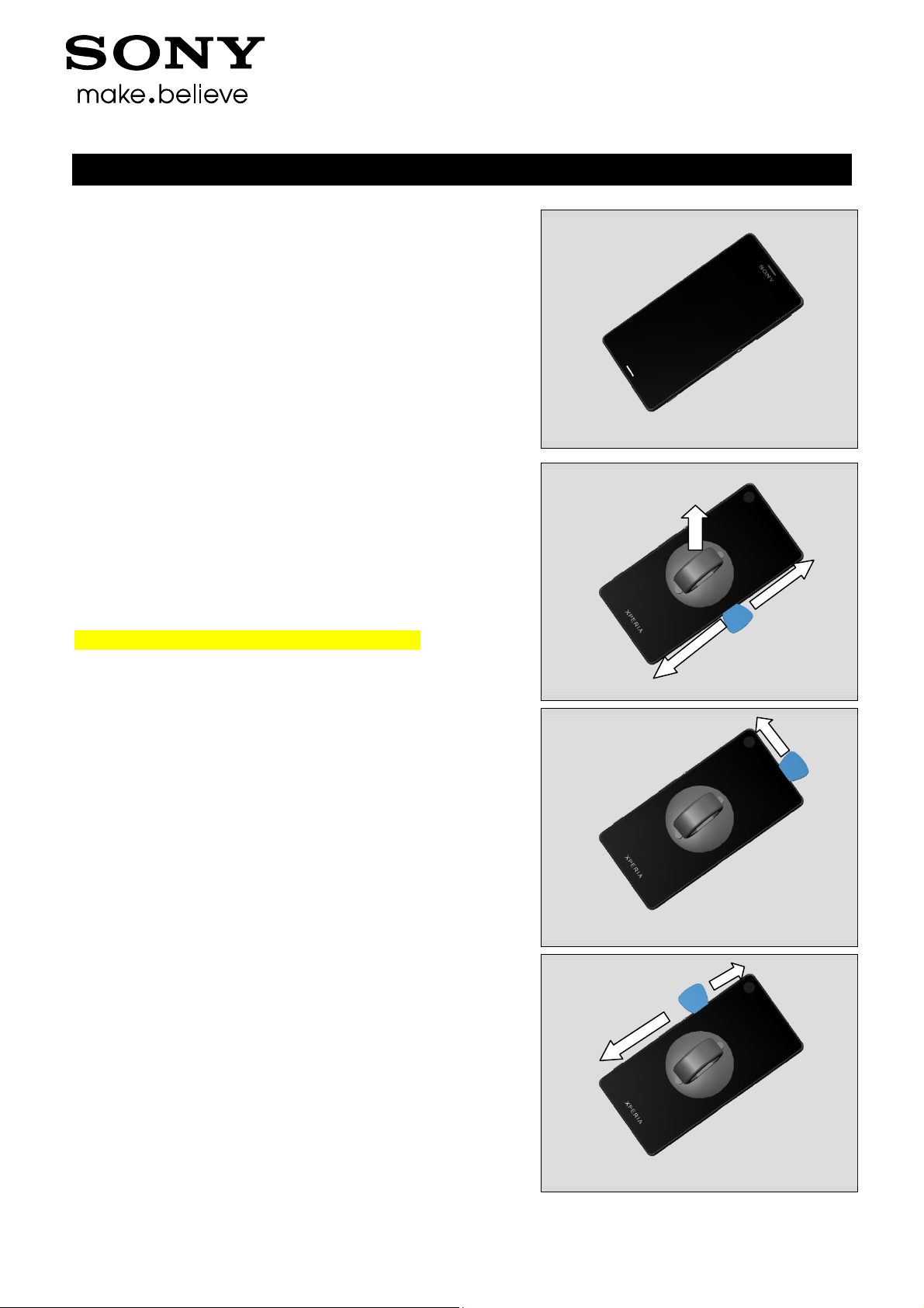
Close the Cap SD
3.2 Rear Panel
Use Suction cup to get space for inserting the Guitar Pick.
Gently slide the Guitar Pick along to release all sides of the
Rear Panel.
Note! Start in the middle of the right long side!
Working Instructions (mech)
1288-9438 Rev 2
© Sony Mobile Communications AB – Company Internal 10(97)
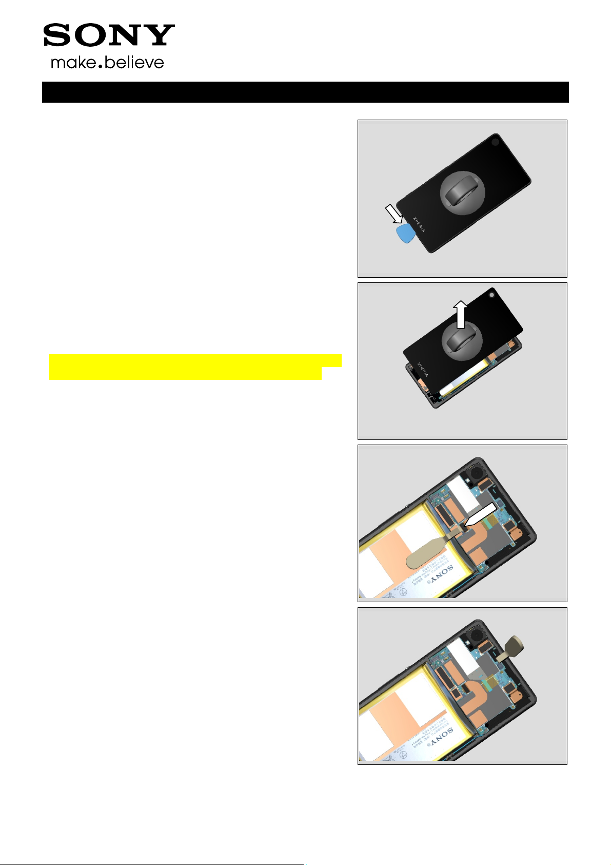
Disassembly
Remove the Rear Panel by using the Suction cup.
Note! Be careful when removing the Rear Panel due to the
adhesive between Embedded Battery and Rear Panel.
Working Instructions (mech)
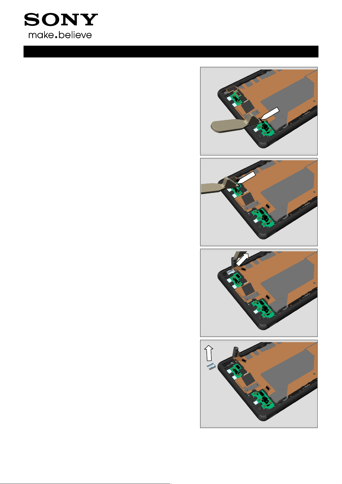
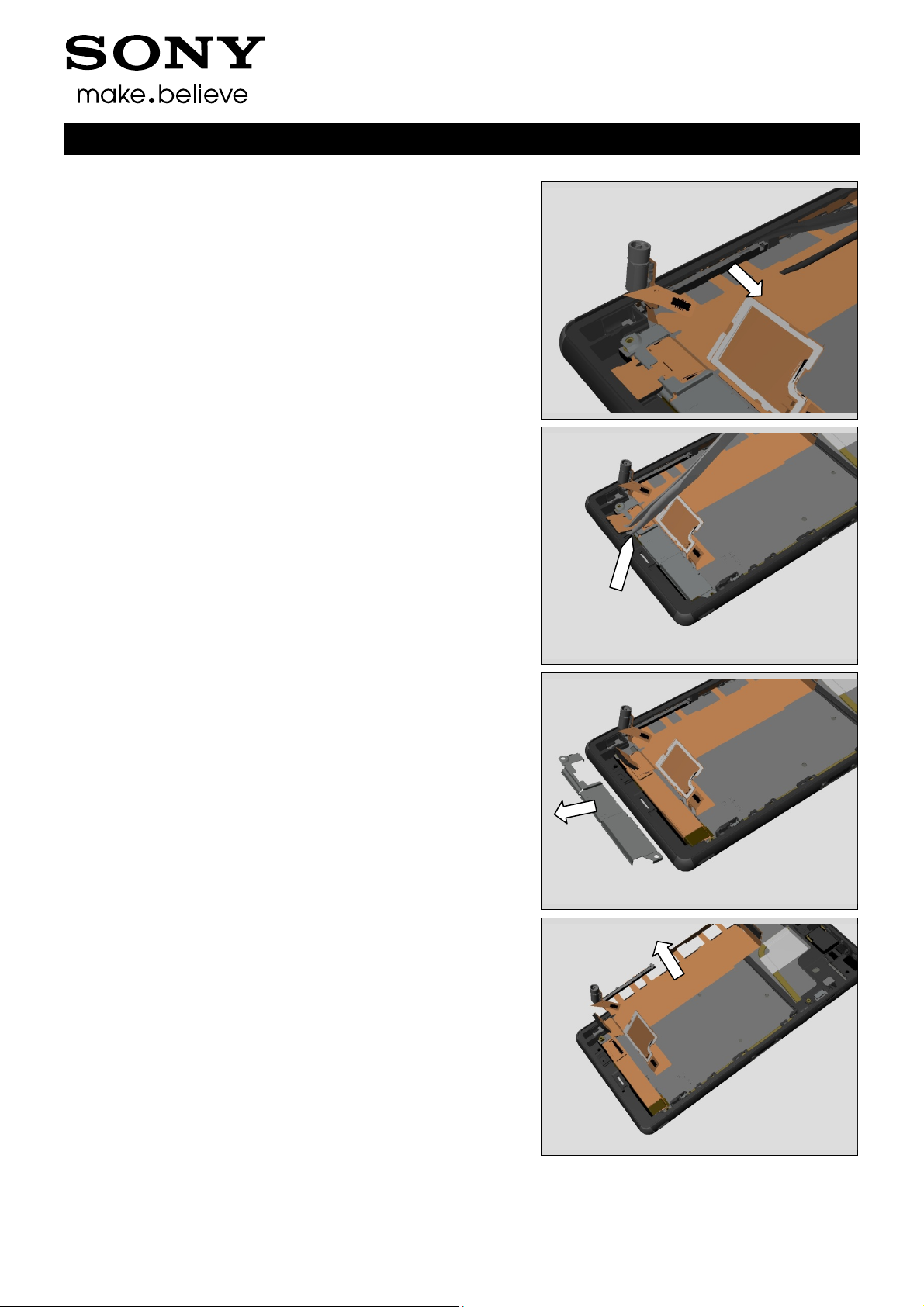
Use a Front Opening Tool to disconnect the BtB connector.
3.3 Sub Antenna
Remove the Sub Antenna by using a Front Opening Tool.
1288-9438 Rev 2
© Sony Mobile Communications AB – Company Internal 11(97)
Disassembly
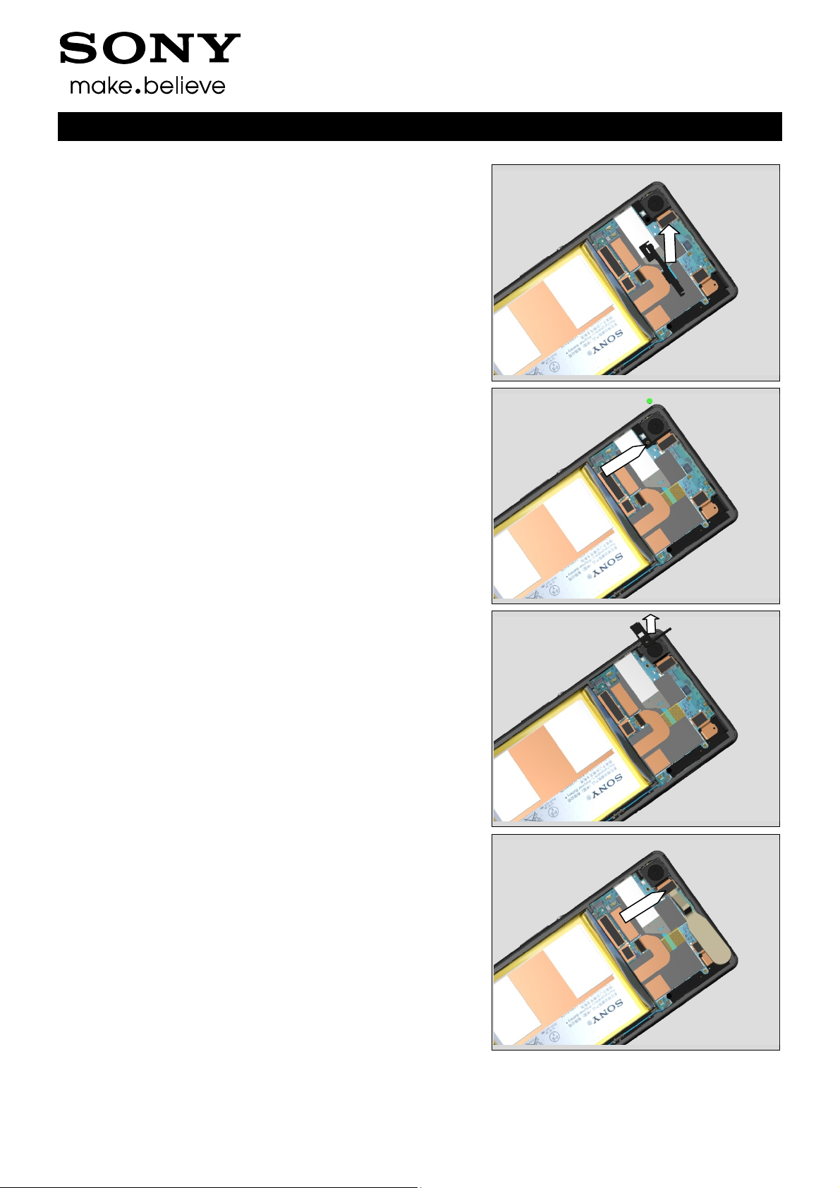
Remove the Sub Antenna.
3.4 Holder Main Camera
Remove the Screw Other Len:2.6 Diam:1.4 by using a
screwdriver with Bits (JCIS No 0).
Working Instructions (mech)
Remove Holder Main Camera
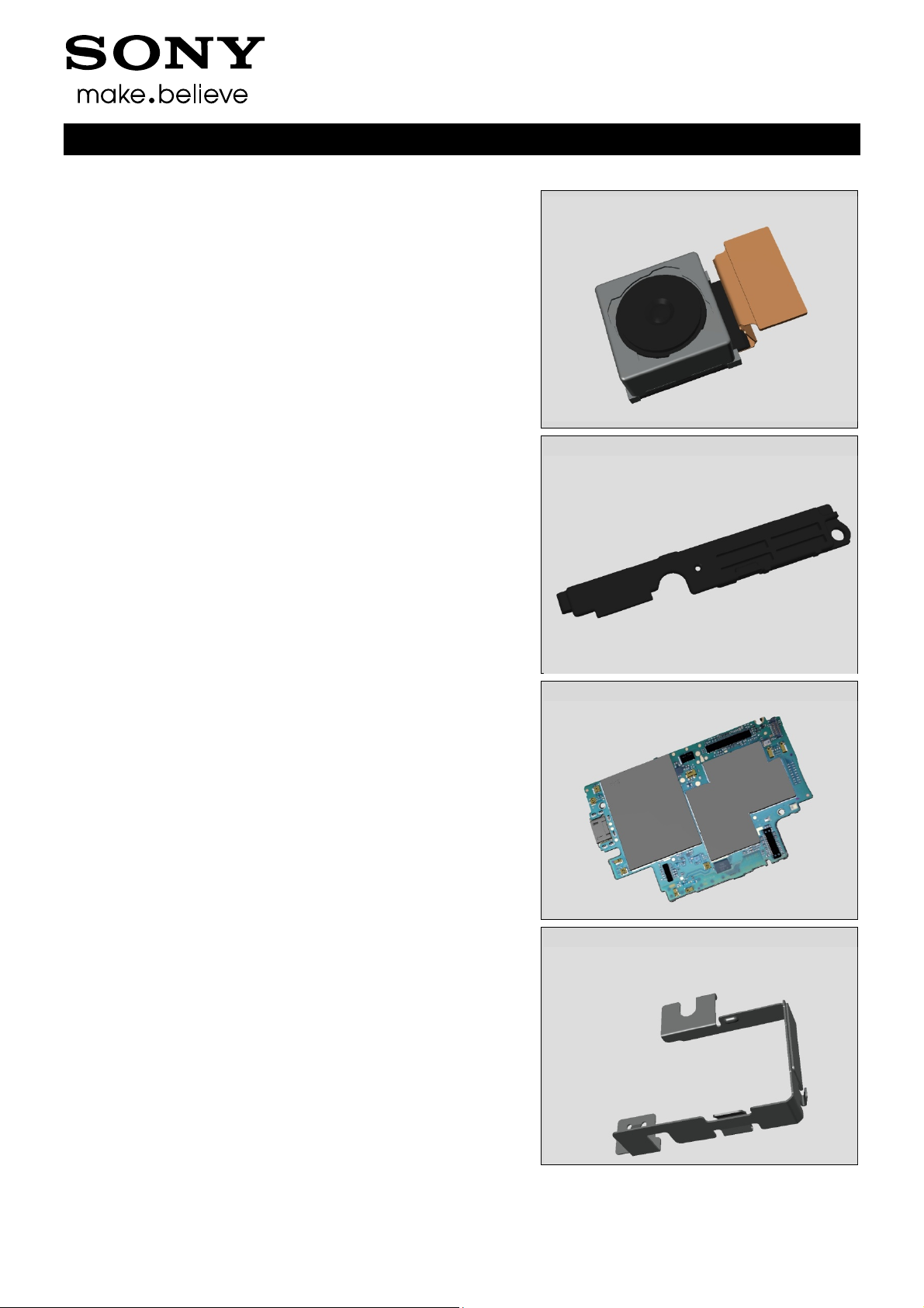
3.5 Main Camera
Use a Front Opening Tool to disconnect the BtB connector.
1288-9438 Rev 2
© Sony Mobile Communications AB – Company Internal 12(97)
Disassembly
Remove the Camera. Be careful not to damage it.
3.6 Antenna BT + WLAN
Remove the Screw Other Len:2.6 Diam:1.4 by using a
screwdriver with Bits (JCIS No 0).
Working Instructions (mech)
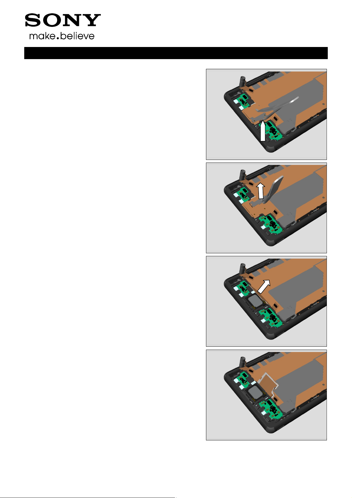
Remove the Antenna BT + WLAN with fingers.
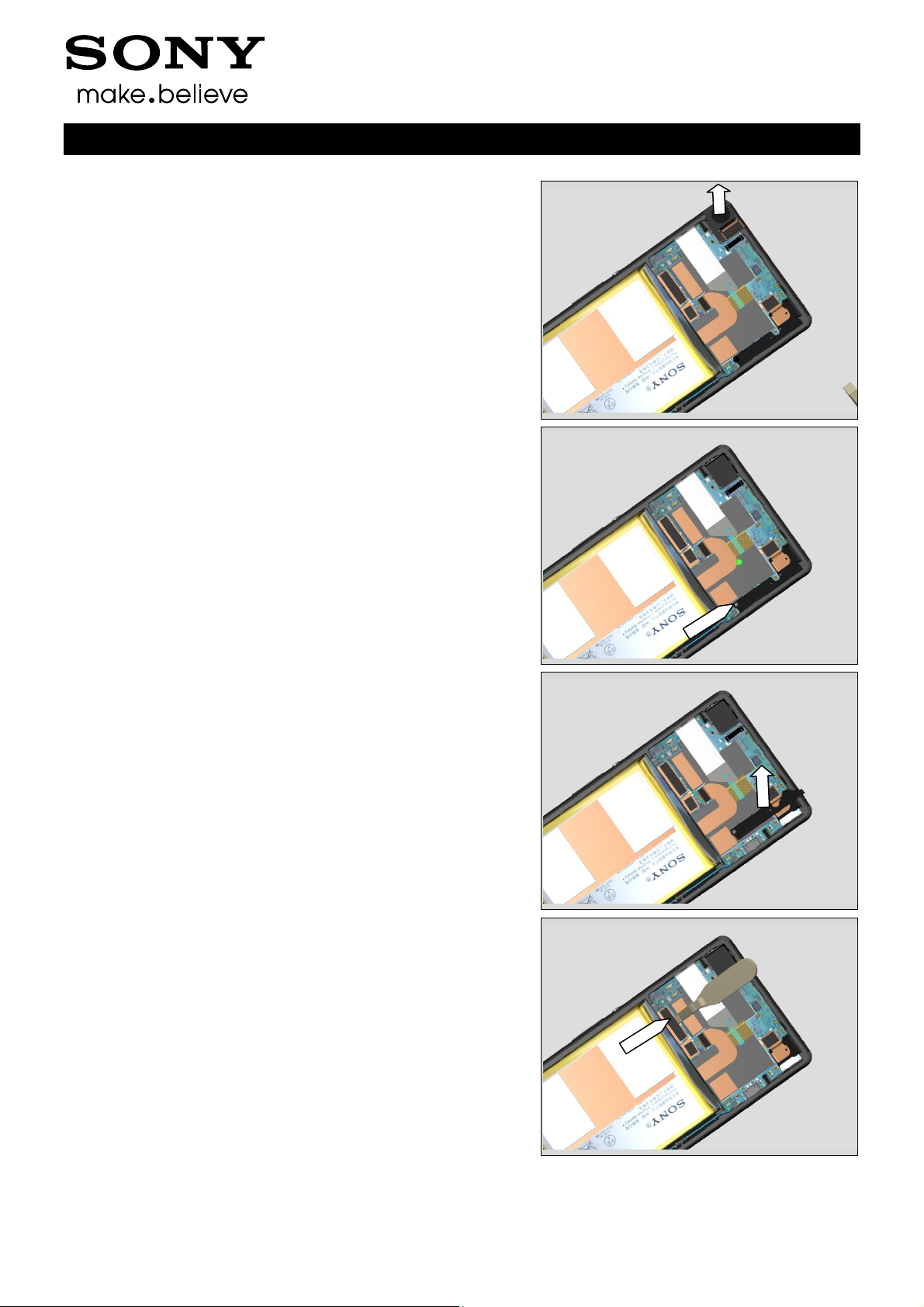
3.7 Main PBA
Use a Front Opening Tool to disconnect the BtB connector
for Relay FPC.
1288-9438 Rev 2
© Sony Mobile Communications AB – Company Internal 13(97)
Disassembly
Use a Front Opening Tool to disconnect the BtB connector
for Charger FPC.
Use a Front Opening Tool to disconnect the BtB connector
for Audio Jack.
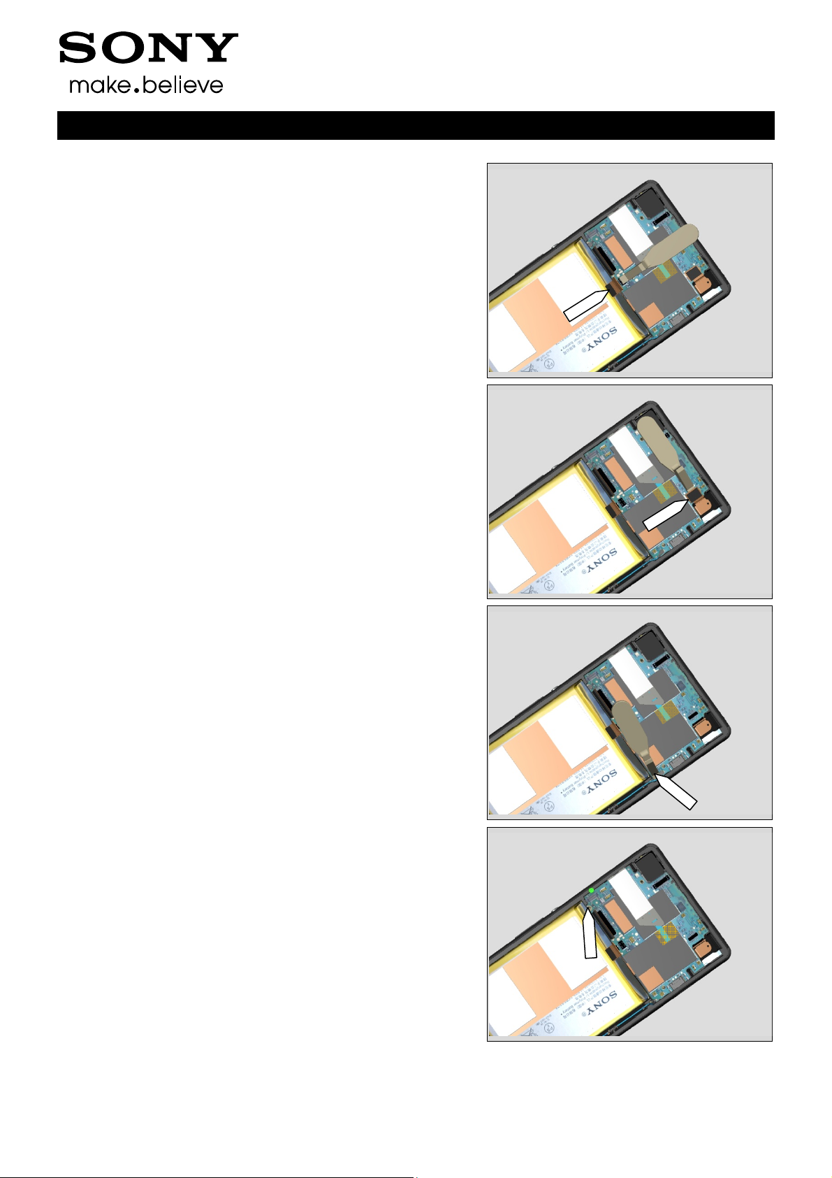
Working Instructions (mech)
Use a Front Opening Tool to disconnect the RF cable
connector.
Remove the Screw Other Len:2.6 Diam:1.4 by using a
screwdriver with Bits (JCIS No 0).
1288-9438 Rev 2
© Sony Mobile Communications AB – Company Internal 14(97)
Disassembly
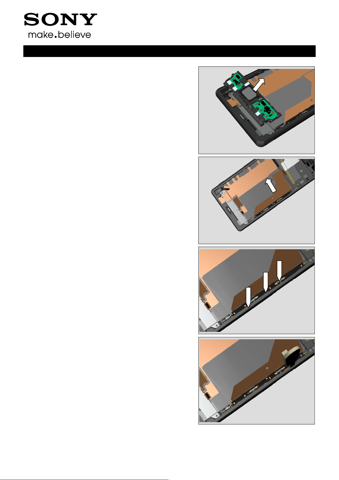
Insert the Front Opening Tool to release the Main PBA.
Remove the Main PBA
Working Instructions (mech)
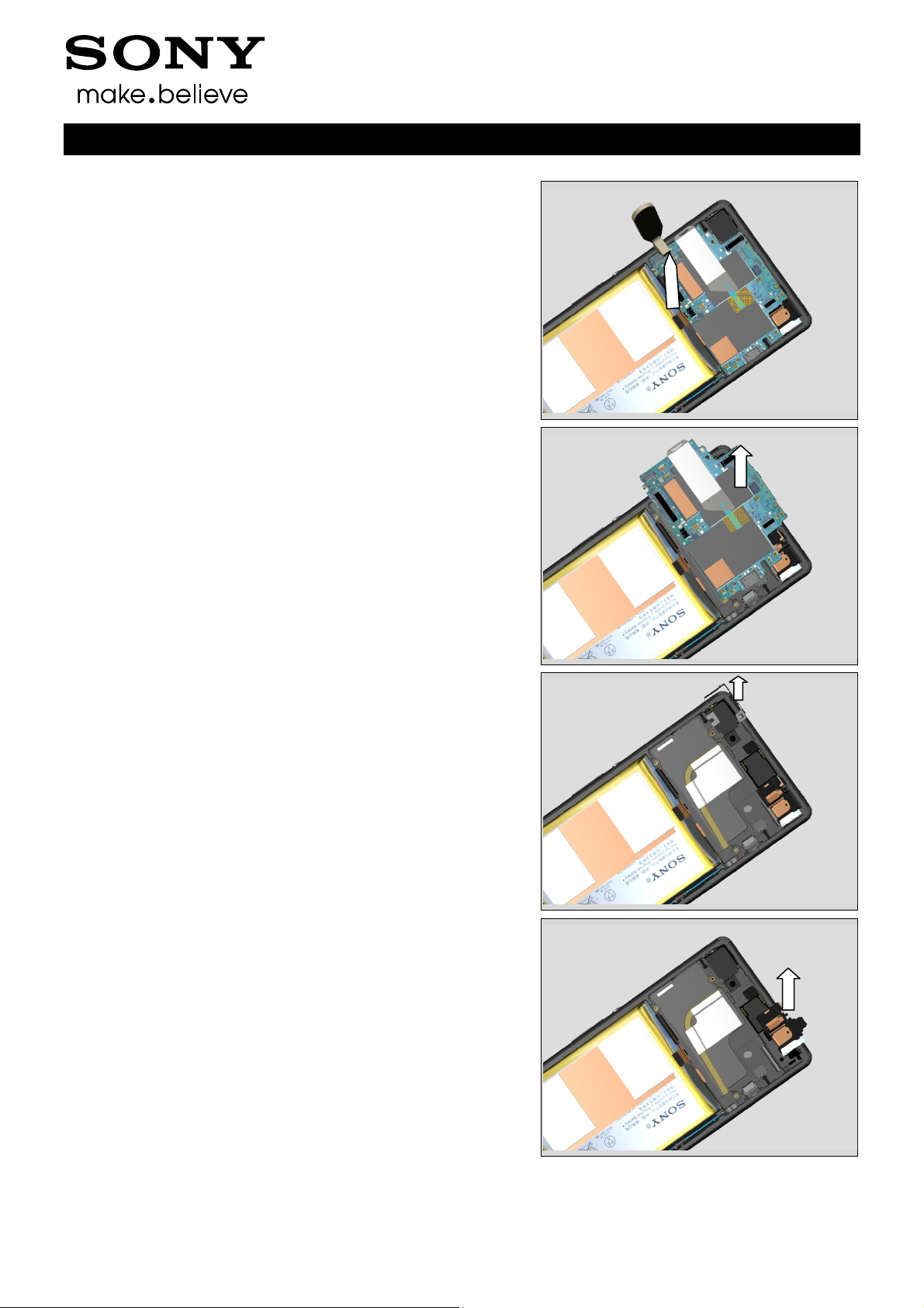
3.8 Shield Main Camera
Remove Shield Main Camera with a pair of tweezers.
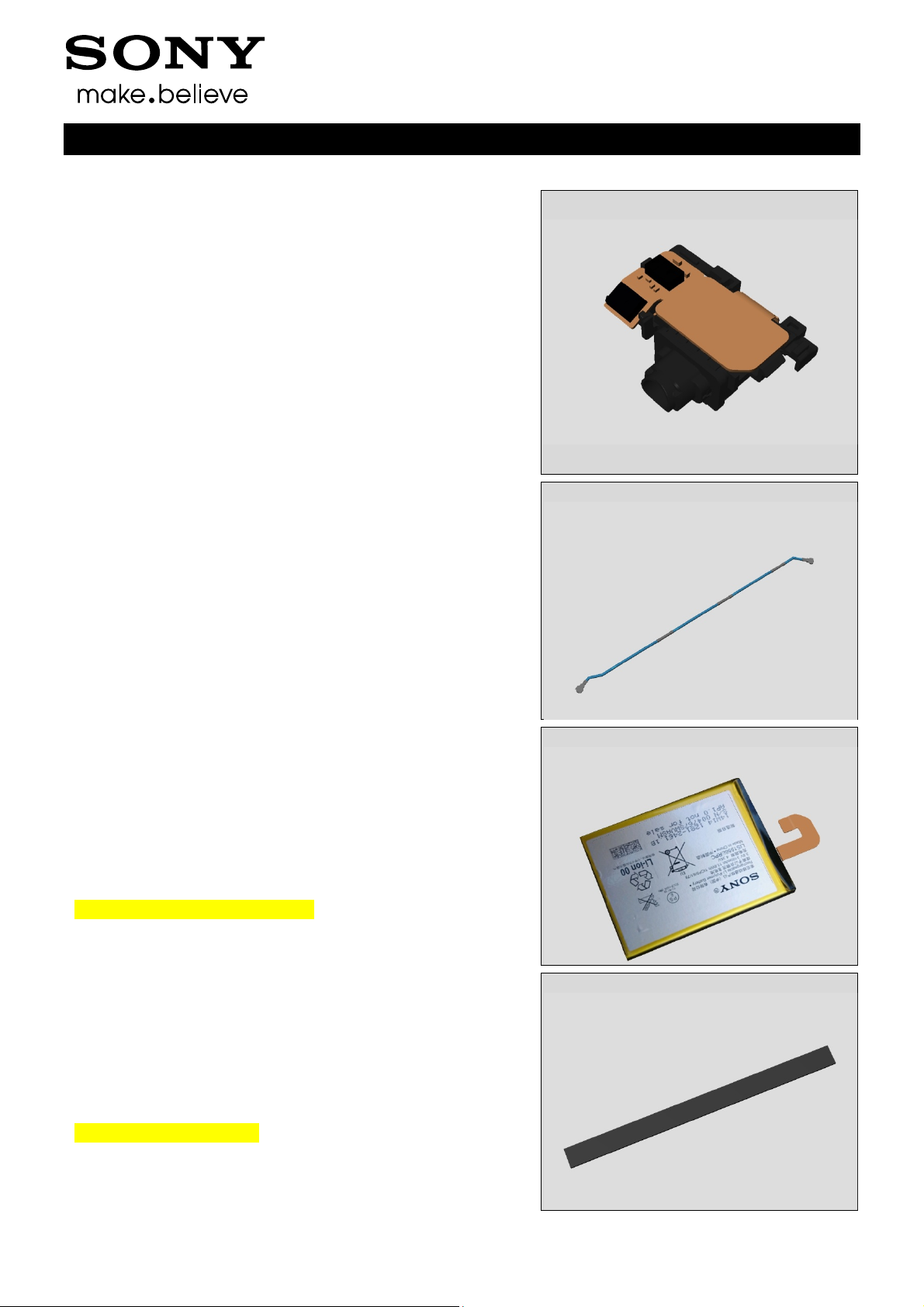
3.9 Audio Jack
Remove the Audio Jack with fingers.
1288-9438 Rev 2
© Sony Mobile Communications AB – Company Internal 15(97)

Disassembly
3.10 RF cable
Use a Front Opening Tool to disconnect the RF cable
connector.
Remove the RF cable with fingers
Working Instructions (mech)
3.11 Embedded Battery
Remove the Embedded Battery by pull the tab (red arrow)
with fingers
3.12 Cushion Battery
Remove the Cushion Battery using a Front Opening Tool
and fingers.
1288-9438 Rev 2
© Sony Mobile Communications AB – Company Internal 16(97)
Disassembly
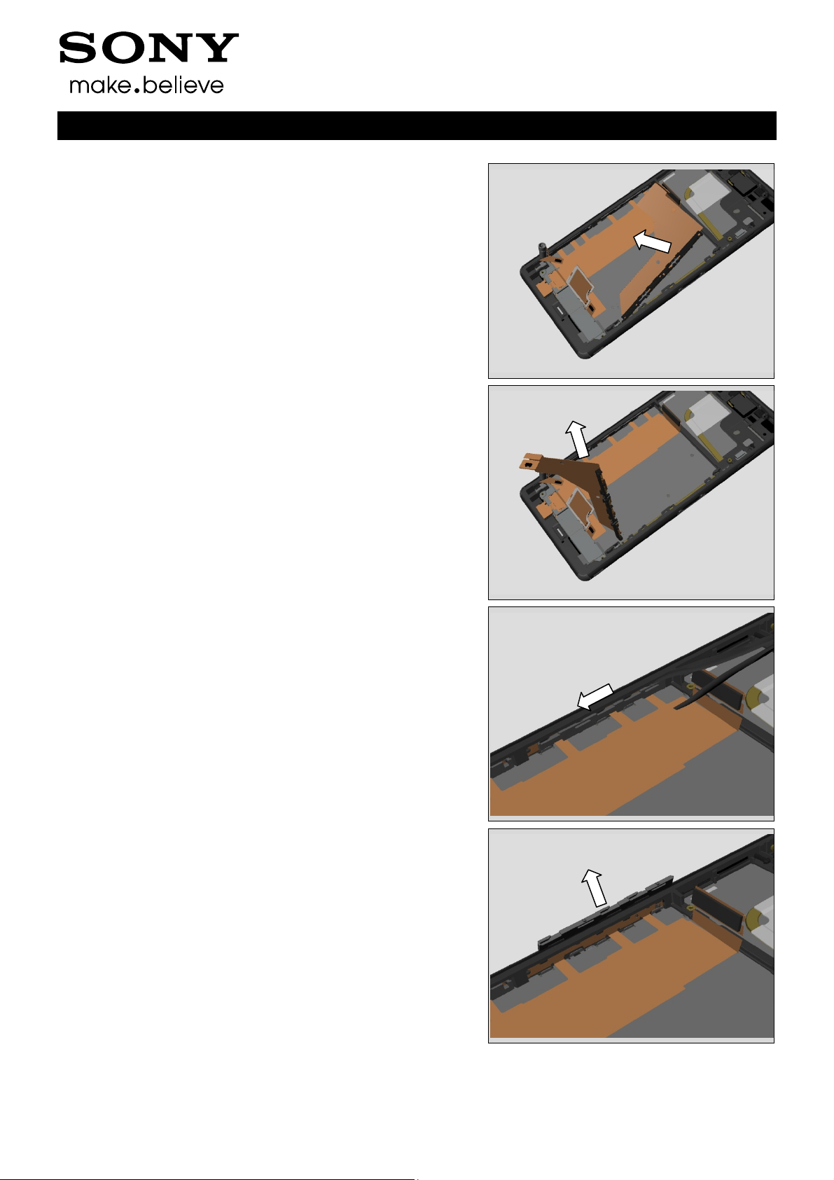
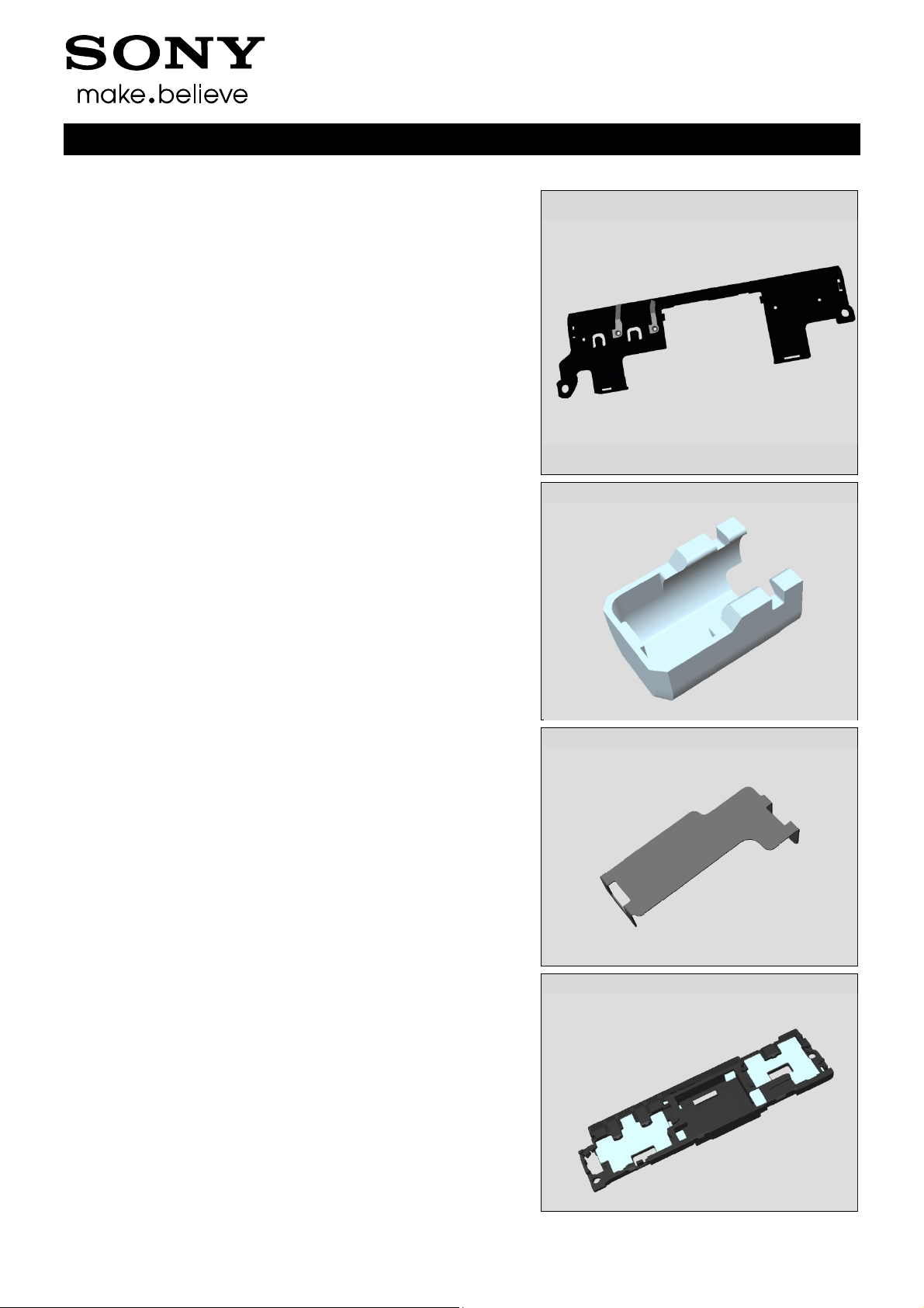
3.13 Main Antenna
Remove the two Screw Other Len:4.0 Diam:1.4 by using a
screwdriver with Bits (JCIS No 0).
Insert the Flex Film Assembly Tool to release left side of
Main Antenna
Working Instructions (mech)
Insert the Flex Film Assembly Tool to release right side of
Main Antenna
Remove Main Antenna with fingers
1288-9438 Rev 2
© Sony Mobile Communications AB – Company Internal 17(97)
Disassembly
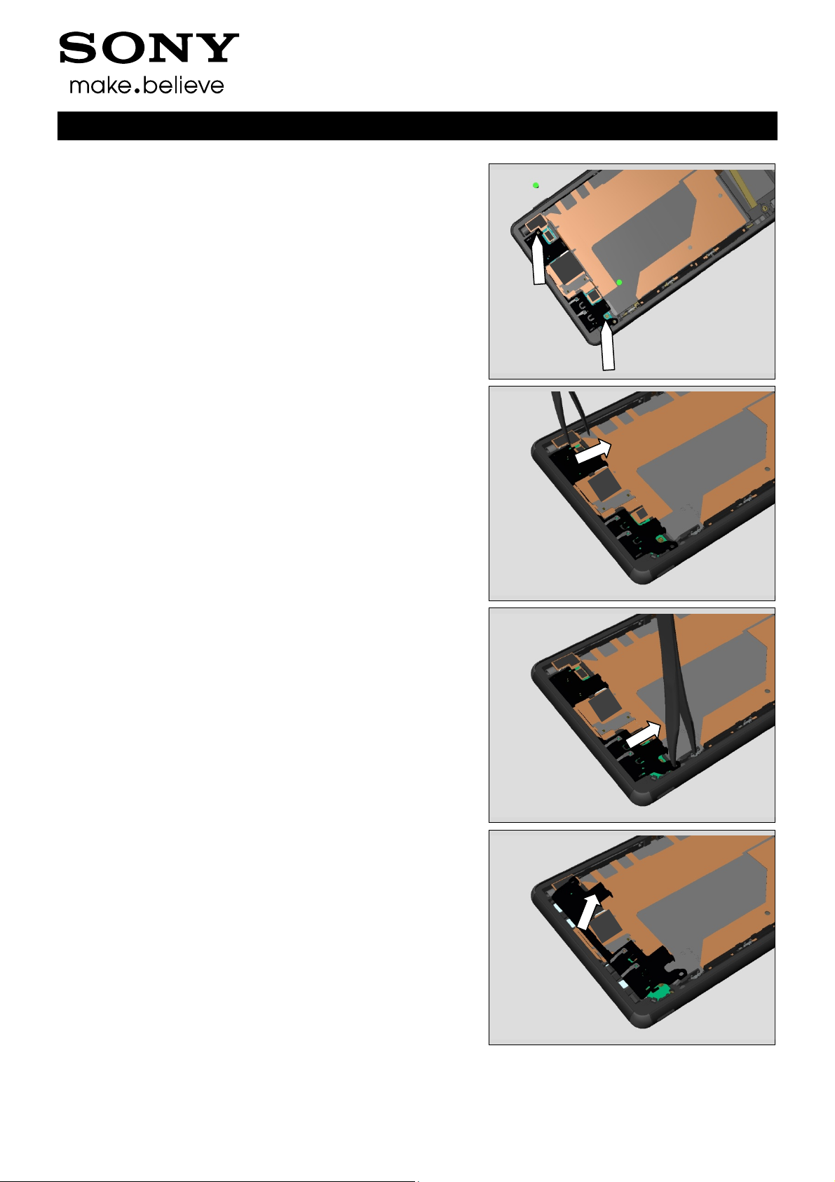
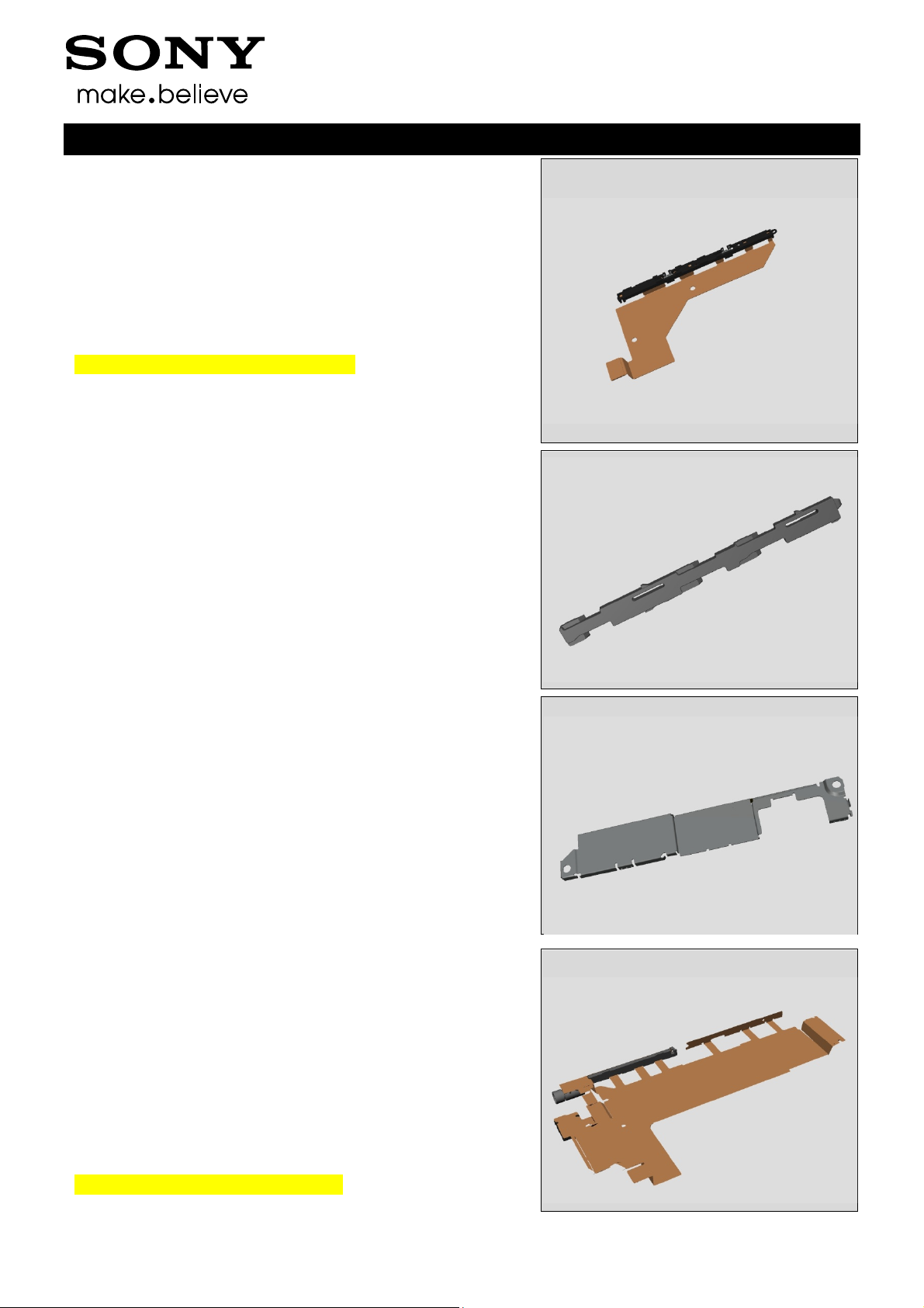
3.14 Holder Vibrator
Use a Front Opening Tool to disconnect the BtB connector.
Use a Front Opening Tool to disconnect the BtB connector.
Working Instructions (mech)
Lift the Vibrator
Remove the Holder Vibrator with a pair of tweezers.
1288-9438 Rev 2
© Sony Mobile Communications AB – Company Internal 18(97)
Disassembly
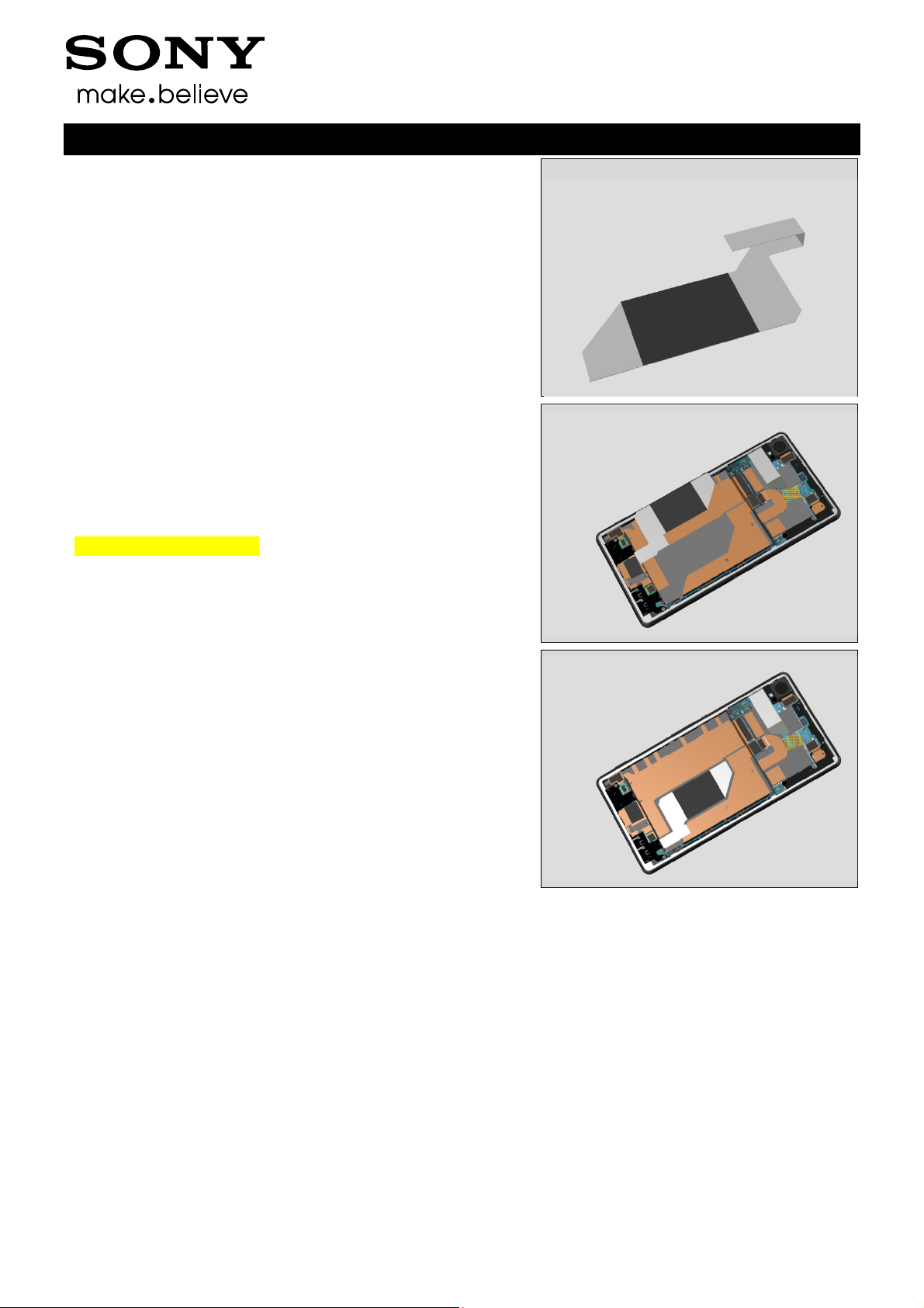
3.15 Plate Speaker
Detach the Plate Speaker with Flex Film Assembly Tool.
Remove the Plate Speaker with Flex Film Assembly Tool.
Working Instructions (mech)
3.16 Holder Speaker sub
assembly
Lift up the Relay FPC over Holder Speaker sub assembly
with a Flex Film Assembly Tool
Unsnap the Holder Speaker sub assembly with fingers
1288-9438 Rev 2
© Sony Mobile Communications AB – Company Internal 19(97)
Disassembly
Remove it.
3.17 Charge FPC
Detach the adhesive under the Charge FPC
Working Instructions (mech)
Charge FPC has three hooks
Detach the Charge FPC from Front Assy using Front
Opening Tool
1288-9438 Rev 2
© Sony Mobile Communications AB – Company Internal 20(97)
Disassembly
Lift up the Charge FPC
Remove the Charge FPC
Working Instructions (mech)
3.18 Holder key volume
Detach the Holder key volume to the left using a Flex Film
Assembly Tool
Remove the Holder key volume
1288-9438 Rev 2
© Sony Mobile Communications AB – Company Internal 21(97)
Disassembly
Unsnap the Holder camera key of Relay FPC
3.19 Plate holder speaker
Detach the Holder Mic sub assembly of Relay FPC from
Front Assy with a Flex Film Assembly Tool.
Working Instructions (mech)
Remove the Plate holder speaker using a pair of tweezers.
3.20 Relay FPC + Front Assy
Detach the adhesive under Relay FPC and remove it
1288-9438 Rev 2
© Sony Mobile Communications AB – Company Internal 22(97)
4 Replacement
4.1 Sim Tray
Follow the 3.1 Disassembly instructions!
Prepare the new Sim Tray.
Follow the 5.20 Reassembly instructions!
4.2 Rear Panel
Follow the 3.2 Disassembly instructions!
Prepare the new Rear Panel.
Follow the 4.26 Installation instructions!
Follow the 5.19 Reassembly instructions!
Working Instructions (mech)
4.3 Sub Antenna
Follow the 3.2 – 3.3 Disassembly instructions!
Prepare the new Sub Antenna.
Follow the 4.61, 4.65 Installation instructions!
Follow the 5.18-5.19 Reassembly instructions!
4.4 Holder Main Camera
Follow the 3.2 and 3.6 Disassembly instructions!
Prepare the new Holder Main Camera.
Follow the 5.17 and 5.19 Reassembly instructions!
1288-9438 Rev 2
© Sony Mobile Communications AB – Company Internal 23(97)
Replacement
4.5 Main Camera
Follow the 3.2 and 3.4-3.5 Disassembly instructions!
Prepare the new Main Camera.
Follow the 5.16-17 and 5.19 Reassembly instructions!
4.6 Antenna BT + WLAN
Follow the 3.2 and 3.6 Disassembly instructions!
Prepare the new Antenna BT + WLAN.
Follow the 4.52 Installation instructions!
Follow the 5.15 and 5.19 Reassembly instructions!
Working Instructions (mech)
4.7 Main PBA
Follow the 3.1 – 3.7 Disassembly instructions!
Follow the 4.66 Removal instructions!
Prepare the new Main PBA.
Follow the 4.66 Installation instructions!
Follow the 5.14 – 5.20 Reassembly instructions!
4.8 Shield Main Camera
Follow the 3.1 – 3.8 Disassembly instructions!
Prepare the new Shield Main Camera.
Follow the 4.44 Installation instructions!
Follow the 5.13 – 5.20 Reassembly instructions!
1288-9438 Rev 2
© Sony Mobile Communications AB – Company Internal 24(97)
Replacement
4.9 Audio Jack
Follow the 3.1 – 3.7 and 3.9 Disassembly instructions!
Prepare the new Audio Jack.
Follow 5.12 and 5.14 – 5.20 Reassembly instructions!
Working Instructions (mech)
4.10 RF cable
Follow the 3.2 and 3.10 Disassembly instructions!
Prepare the new RF cable.
Follow the 5.11 and 5.19 Reassembly instructions!
4.11 Embedded Battery
Follow the 3.2 and 3.11 Disassembly instructions!
Prepare the new Embedded Battery.
Follow the 4.36 Installation instructions!
Follow the 5.10 and 5.19 Reassembly instructions!
Visual Inspection of the Battery.
4.12 Cushion Battery
Follow the 3.2 and 3.11-3.12 Disassembly instructions!
Prepare the new Cushion Battery.
Follow the 5.9-5.10 and 5.19 Reassembly instructions!
Scrap! Not to be reused!
1288-9438 Rev 2
© Sony Mobile Communications AB – Company Internal 25(97)
Replacement
4.13 Main Antenna
Follow the 3.2 and 3.11-3.13 Disassembly instructions!
Prepare the new Main Antenna.
Follow the 5.8-5.10 and 5.19 Reassembly instructions!
Working Instructions (mech)
4.14 Holder Vibrator
Follow the 3.2 and 3.11-3.13 Disassembly instructions!
Prepare the new Holder Vibrator.
Follow the 5.7-5.10 and 5.19 Reassembly instructions!
4.15 Plate Speaker
Follow the 3.2 and 3.11-3.14 Disassembly instructions!
Prepare the new Plate Speaker.
Follow the 5.8-5.10 and 5.19 Reassembly instructions!
4.16 Holder Speaker sub
assembly
Follow the 3.2 and 3.11-3.14 Disassembly instructions!
Follow the 4.30, 4.67, 4.66, 4.54 Removal instructions!
Prepare the new Holder Speaker sub assembly
Follow the 4.30, 4.54, 4.25 4.66, 4.67
Installation instructions!
Follow the 5.8-5.10 and 5.19 Reassembly instructions!
1288-9438 Rev 2
© Sony Mobile Communications AB – Company Internal 26(97)
Replacement
4.17 Charge FPC
Follow the 3.2, 3.10-312 and 3.17 Disassembly instructions!
Prepare the new Charge FPC.
Follow the 4.36 Installation instructions!
Follow the 5.4, 5.9-5.11 and 5.19 Reassembly instructions!
Visual Inspection of the Charge FPC.
4.18 Holder key volume
Follow the 3.11-312 and 3.17 Disassembly instructions!
Prepare the new Holder key volume.
Follow the 5.9-5.10 and 5.19 Reassembly instructions!
Working Instructions (mech)
4.19 Plate holder speaker
Follow the 3.2, 3.11-3.16 and 3.19 Disassembly instructions!
Prepare the new Plate holder speaker.
Follow the 5.2, 5.5-5.10 and 5.8 Reassembly instructions!
4.20 Relay FPC
Follow the 3.2, 3.11-3.16 and 3.19 -3.20 Disassembly
instructions!
Follow the 4.27, 4. 28 Removal instructions!
Prepare the new Relay FPC.
Follow the 4.27, 4. 28, 4.36, 4.40, 4.42, 4.43, 4.47
Installation instructions!
Follow the 5.1-5.2, 5.5-5.10 and 5.8 Reassembly
instructions!
Visual Inspection of the Relay FPC.
1288-9438 Rev 2
© Sony Mobile Communications AB – Company Internal 27(97)
Replacement
4.21 Front Assy
Follow the 3.1 – 3.20 Disassembly instructions!
Follow the 4.48, 4.53 Removal instructions!
Prepare the new Front Assy.
Follow the 4.63, 4.64 Installation instructions!
Follow the 5.1 – 5.20 Reassembly instructions!
Working Instructions (mech)
1288-9438 Rev 2
© Sony Mobile Communications AB – Company Internal 28(97)
Replacement
4.22 Adhesive Battery Front
Follow the 3.2 and 3.11 Disassembly instructions!
Carry out the Removal as described below.
Prepare the new Adhesive Battery Front.
Carry out the Installation as described below.
Follow the 5.10 and 5.19 Reassembly instructions!
REMOVAL
Remove the Adhesive Battery Front with fingers.
Scrap! Not to be reused!
Working Instructions (mech)
INSTALLATION
Attach the Adhesive Battery Front with fingers.
1288-9438 Rev 2
© Sony Mobile Communications AB – Company Internal 29(97)
Replacement:
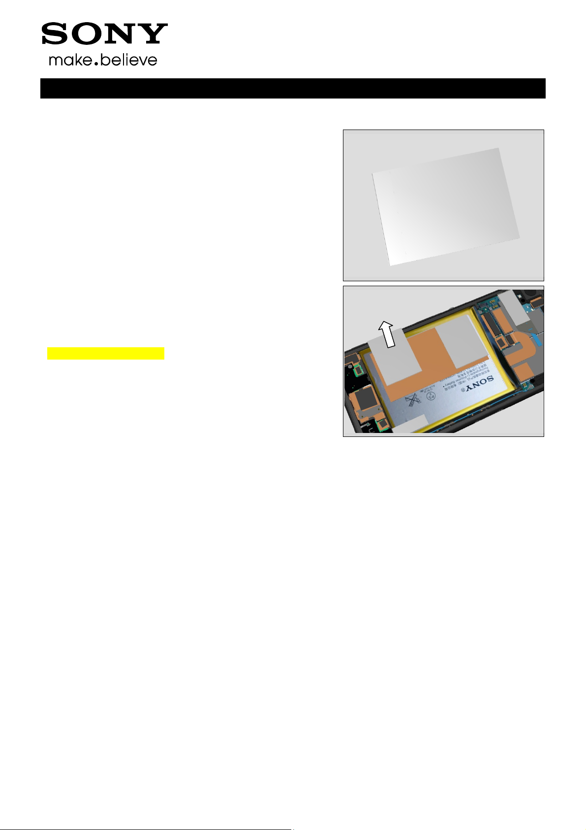
4.23 Adhesive Battery Rear
Follow the 3.2 Disassembly instructions!
Carry out the Removal as described below.
Prepare the new Adhesive Battery Rear.
Carry out the Installation as described below.
Follow the 5.19 Reassembly instructions!
REMOVAL
Detach to remove the Adhesive Battery Rear with the Flex
Film Assembly Tool
Scrap! Not to be reused!
INSTALLATION
Place a new Adhesive Battery Rear on the Embedded
Battery using a Flex Film Assembly Tool.
Working Instructions (mech)
1288-9438 Rev 2
© Sony Mobile Communications AB – Company Internal 30(97)
 Loading...