

Sony D6633, Xperia Z3 Test Instructions
TM
D6663, L55u, L55t
Test Instructions
- mechanical -
1291-7740 Rev 2
Sony Mobile Communications AB – Company Internal
Xperia
Z3

Company Internal
Test Instructions (mech)
CONTENTS
1 Pre-Test Preparation ...................................................................... 4
1.1 Process flow – Water Resistance Test (WRT) for incoming units .... 4
1.2 Hardware ............................................................................................... 5
1.2.1 Water indicator inspection .......................................................................... 5
1.3 Test Enablers ........................................................................................ 6
1.3.1 Test Enablers ............................................................................................... 6
1.4 Software ................................................................................................ 7
1.4.1 Software update ........................................................................................... 7
2 Tests ................................................................................................ 8
2.1 Service Test Mode ................................................................................ 8
2.2 Service Tests ........................................................................................ 9
2.2.1 Keyboard & Switch ...................................................................................... 9
2.2.1 Touch Screen ............................................................................................... 9
2.2.2 Display .......................................................................................................... 9
2.2.3 LED/Illumination ........................................................................................ 10
2.2.4 Speaker ....................................................................................................... 10
2.2.5 Stereo speaker ........................................................................................... 10
2.2.6 Earphone .................................................................................................... 11
2.2.7 Microphone ................................................................................................ 11
2.2.8 Secondary Microphone ............................................................................. 12
2.2.9 Vibrator ....................................................................................................... 12
2.2.10 Camera ....................................................................................................... 13
2.2.11 Secondary Camera .................................................................................... 13
2.2.12 Flash LED ................................................................................................... 13
2.2.13 Antenna RX Diversity ................................................................................ 14
2.2.14 Bluetooth .................................................................................................... 14
2.2.15 WLAN .......................................................................................................... 15
2.2.16 NFC ............................................................................................................. 15
2.2.17 GPS ............................................................................................................. 15
2.2.18 Compass .................................................................................................... 16
2.2.19 Accelerometer ............................................................................................ 16
2.2.20 Gyroscope .................................................................................................. 17
2.2.21 Ambient Light Sensor ............................................................................... 17
2.2.22 Proximity switch ........................................................................................ 18
2.2.23 Hall Element ............................................................................................... 18
2.2.24 Pressure Sensor ........................................................................................ 18
2.2.25 Real time clock .......................................................................................... 19
2.2.26 Total call time ............................................................................................. 19
2.2.27 Storage ....................................................................................................... 19
2.2.28 Security ...................................................................................................... 20
2.2.29 FM Radio .................................................................................................... 20
2.2.30 Verify certificates ....................................................................................... 21
2.2.31 TV-Out Test ................................................................................................ 21
1291-7740 Rev 2
Sony Mobile Communications AB –
2(29)
Company Internal
Test Instructions (mech)
2.3 Manual Tests ...................................................................................... 23
2.3.1 SIM test ....................................................................................................... 23
2.3.2 Data Communication test ......................................................................... 23
2.3.3 Audio Jack test .......................................................................................... 24
2.3.4 Charging (Charger or Computer) ............................................................. 25
2.3.5 Battery Test ................................................................................................ 27
2.3.6 Network Test .............................................................................................. 28
3 Revision History ........................................................................... 29
For general information about test procedures, refer to
1220-1333: Generic Repair Manual – mechanical
1291-7740 Rev 2
Sony Mobile Communications AB –
3(29)
Company Internal
Test Instructions (mech)
1 Pre-Test Preparation
1.1 Process flow – Water Resistance
Test (WRT) for incoming units
Follow the process according to 1269-3536 Water Resistant Test for PC - mechanical in the including
document Test Instruction WRT.
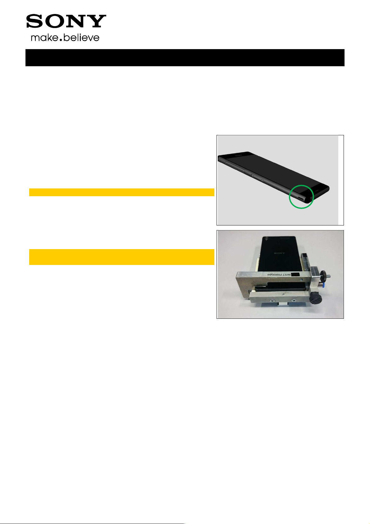
Close all Caps (Cap SIM and Cap USB) before WRT.
The WRT Vent hole is shown as photo.
Note! The circle area is the WRT Vent hole.
Install the “WRT Inlay plate” into the generic “WRT Generic
Side Inlay”.
Note: The unit’s back side should be up in the WRT
fixture!
Make sure the arm and the unit is aligned to the Generic
Inlay side, the side without gasket.
Connect phone according to 1269-3536 Water Resistant
Test for PC - mechanical in the including document Test
Instruction WRT.
1291-7740 Rev 2
Sony Mobile Communications AB –
4(29)

Company Internal
Pre-Test Preparations
1.2 Hardware
1.2.1 Water indicator inspection
Before starting any tests the Liquid Indicator has to be
checked.
The 1st indicator is located on Front Assy as shown.
Test Instructions (mech)
The 1st indicator can be checked as shown in this picture
under Cap SIM.
The 2nd indicator is located on Front Assy as shown.
The 2nd indicator can be checked as shown in this picture
under Cap USB.
1291-7740 Rev 2
Sony Mobile Communications AB –
5(29)
Company Internal
3
6
8
Pre-Test Preparations
1.3 Test Enablers
1.3.1 Test Enablers
These are items on the phone that are used during the test
of the unit.
Note! The product supports only Nano SIM!
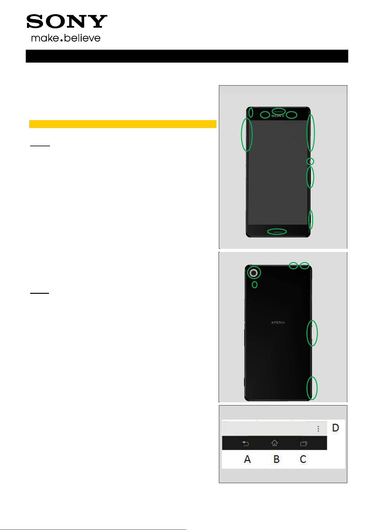
Front:
1. On/Off Key
2. Volume up/down Key
3. Camera Key
4. Ambient Light Sensor& Proximity Switch
5. Earphone/Speaker top port
6. Front Camera
7. SIM Cover (D6633/L55u: two Nano SIM; L55t:
one Nano SIM)
8. Main MIC hole/ Speaker bottom port
9. USB Cover (USB and Micro SD)
10. Notification LED
Test Instructions (mech)
10
4
5
9
7
1
2
Back:
11. Camera
12. Flash LED
13. Second MIC hole(Top side)
14. Audio Jack(Top side)
15. Magnetic connector (to dock)
16. Strap hole/WRT vent Hole
A. Back key
B. Home key
C. Task key
D. Menu key
11
12
13
14
15
16
1291-7740 Rev 2
Sony Mobile Communications AB –
6(29)
Company Internal
Test Instructions (mech)
Pre-Test Preparations
1.4 Software
1.4.1 Software update
1.4.1.1 Software version verification
Check the software version of the phone for fault verification. The latest improvements are found on
the support pages under the support news: http://www.sonymobile.com/global-en/support/.
• Start up the phone
• Make sure the phone is in call setup.
• Press the following keypad combination: *#*#7378423#*#* (i.e. *#*#service#*#*)
• Select ‘Service info’
• Select ‘Software info’
• Check the software file revisions and, if needed, update as described below:
For more information, refer to 1220-1333: Generic Repair Manual - mechanical
1.4.1.2 Software version update
Mandatory first repair action!
Use the USB cable to connect with the Micro USB connector of the phone for this purpose!
Ensure the phone is powered off and proceed as follows:
• Open the Emma application and log in.
• Press and hold the volume down key on the phone, connect the phone to the USB cable and then
release the volume down key.
• Select the appropriate service and follow the on-screen instructions.
Note: For phones with eMMC flash memory (built in “SD card” memory), the only service which
erase this eMMC memory is Service’s “Refurbish” and “Customize”.
See also emma User Guide info.
http://software.sonymobile.com/emma/documents/emma_user_guide.pdf
(see “Service Types” and “Aspects of large files”)
In Swap flow, when change a phone from Customer A to Customer B, always use the service
Customization script.
1291-7740 Rev 2
Sony Mobile Communications AB –
7(29)
Company Internal
Test Instructions (mech)
2 Tests
2.1 Service Test Mode
Stamina mode needs to be turned off before entering
Service Test Mode
Settings -> Power management -> STAMINA mode
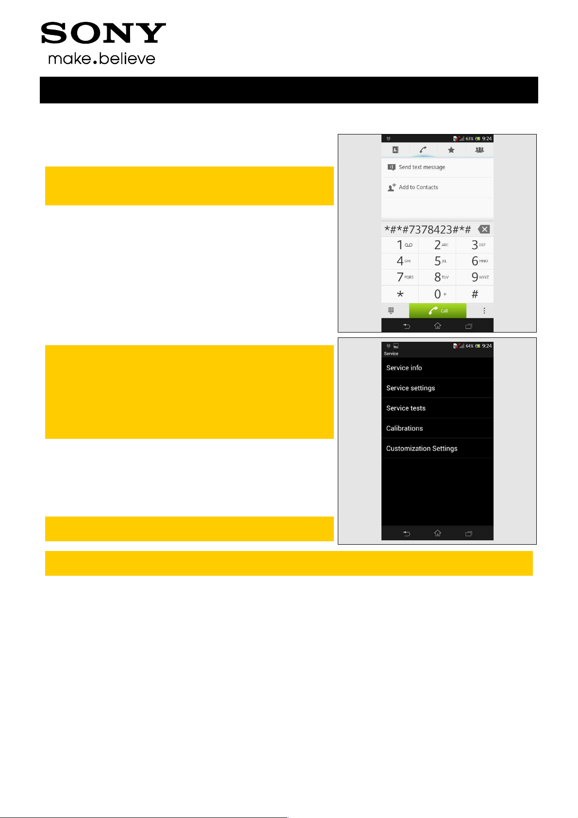
• Start up the phone, go to call setup.
• Press the following keypad combination: *#*#7378423#*#*
(i.e. *#*#service#*#*)
Service info: information about Model, Software,
Simlock, Configuration (IMEI, bands, codec’s)
,Firmware, WLAN Mac address etc.
Service settings: Do not use
Service test: Follow instruction below
Calibration: Do not use
Customization Settings: Do not use.
• Select ‘Service tests’
• Select one of the tests and follow the test instructions as
described below
• To stop the test and return to the ‘Service tests’ menu,
press the Back key
For more information, refer to
1220-1333: Generic Repair Manual - mechanical
The following pictures will show a simplified basic phone for a general visualization of the
service tests!
1291-7740 Rev 2
Sony Mobile Communications AB –
8(29)
Company Internal
Tests
2.2 Service Tests
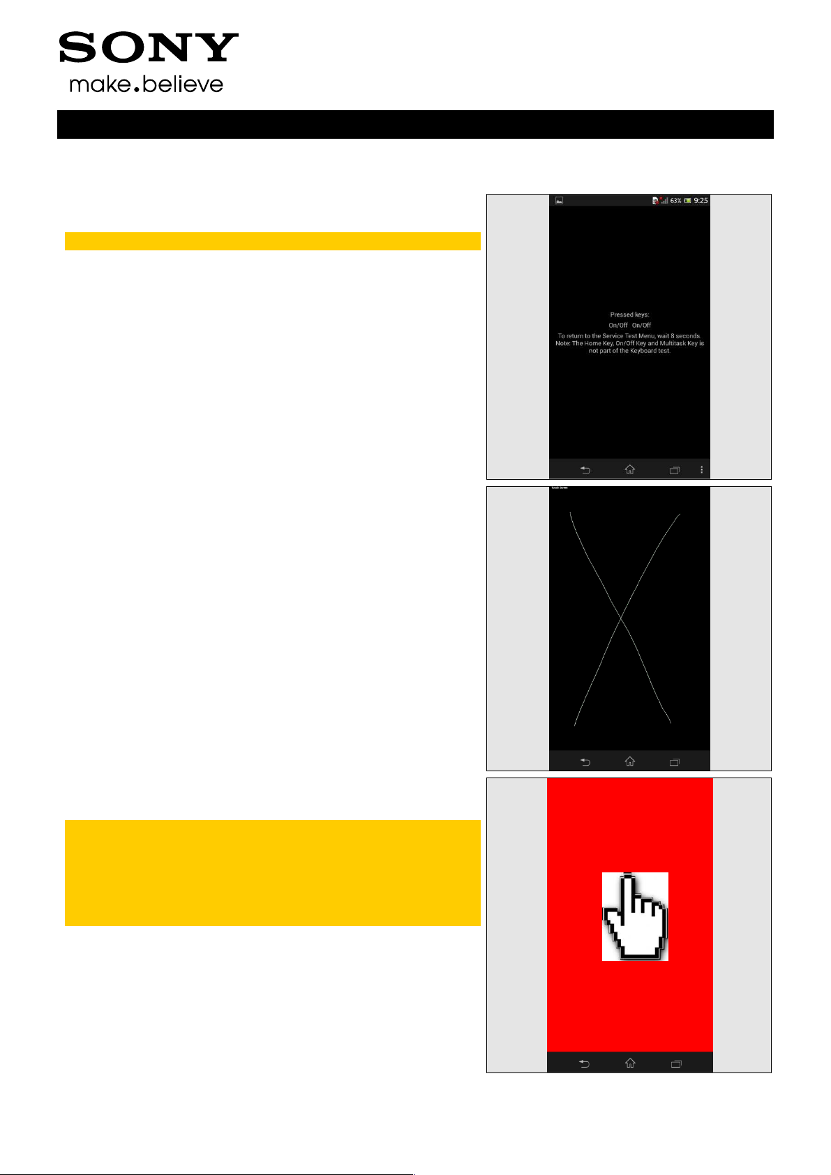
2.2.1 Keyboard & Switch
To return to the Service Test Menu, wait for 8 seconds.
Press all keys:
- Back key:
- Home key:
- Task navigation key:
Menu to return
- Menu key:
- Power key: the
more time
- Volume up key:
- Volume down key:
- Auto Focus key (short press) / Camera key:
notification on screen
will leave the Service tests menu,
taskbar will be shown, press Service
notification on screen
screen will go black, press the Power key one
notification on screen
notification on screen
notification
Test Instructions (mech)
2.2.1 Touch Screen
Move a finger across the touch screen, a line will be drawn
as it touches.
Check all area of the touch screen as indicated by the two
lines.
Press the Back key to return to the Service Test Menu.
2.2.2 Display
Minor variations in the display’s brightness and color
may occur between phones.
If any tiny bright dots on the display are found, this
indicates defective pixels which occur when individual
dots have malfunctioned and cannot be adjusted.
Two defective pixels are considered to be acceptable.
Touch the display using a finger. With every touch, the
display will show Nine test patterns of White, Gray, Black,
Red, Green, Blue, Rainbow Colors, Cross-Line, TV Pattern
on the full screen. Make sure that there are no missing
segments and that the colors and contrast are OK.
Press the Back key to return to the Service Test Menu.
1291-7740 Rev 2
Sony Mobile Communications AB –
9(29)
 Loading...