

Working Instructions
- mechanical -
TM
Xperia
D6633,L55u,L50t
1291-7738 Rev 1
© Sony Mobile Communications AB – Company Internal
Z3

CONTENTS
7
Working Instructions (mech)
1 Exterior Views ................................................................................. 4
1.1 D6633, L55u & L50t .............................................................................. 4
2 Tools ................................................................................................ 5
3 Disassembly.................................................................................... 7
3.1 Rear Panel ............................................................................................ 7
3.2 Embedded Battery ............................................................................... 8
3.3 Cover Holder –A, Sub Antenna, Antenna BT + WLAN ....................... 9
3.4 Holder Speaker sub assembly .......................................................... 10
3.5 Main PBA ............................................................................................ 12
3.6 Front Assy .......................................................................................... 13
4 Replacement ................................................................................. 14
4.1 SIM Tray .............................................................................................. 14
4.2 Rear Panel .......................................................................................... 14
4.3 Adhesive Rear Panel .......................................................................... 14
4.4 Cushion Battery ................................................................................. 14
4.5 Embedded Battery ............................................................................. 15
4.6 Cover Holder -A .................................................................................. 15
4.7 Sub Antenna ....................................................................................... 16
4.8 Antenna BT + WLAN .......................................................................... 17
4.9 Sheet ACO L & Sheet ACO R ............................................................. 18
4.10 Screw M14×3.3 ................................................................................... 19
4.11 RF Cable ............................................................................................. 20
4.12 Main Antenna ...................................................................................... 21
4.13 Holder Speaker sub assembly .......................................................... 21
4.14 Sub PBA-A & Sheet Sub PBA ............................................................ 22
4.15 Sub PBA-B .......................................................................................... 23
4.16 Film Display BtB ................................................................................. 23
4.17 Front Assy .......................................................................................... 24
4.18 Sub Camera & Sheet Chat Camera ................................................... 25
4.19 Cap USB .............................................................................................. 26
4.20 Cap SIM ............................................................................................... 27
4.21 Core Unit Label ................................................................................... 28
4.22 Gore Sheet(1st mic) ........................................................................... 29
4.23 Loudspeaker B & Grill Receiver Black ............................................. 30
1291-7738 Rev 1
© Sony Mobile Communications AB – Company Internal
4.24 Audio Jack & Cushion Audio Jack FPC BtB .................................... 32
4.25 Charge FPC & Adhesive Charge FPC ............................................... 35
4.26 Relay FPC PBA &Adhesive Relay FPC A &Adhesive Relay FPC B 40
4.27 Holder Mic sub assembly .................................................................. 45
2(86)

Working Instructions (mech)
4.28 Cushion Relay FPC BtB & Cushion Relay FPC bottom BtB &
Cushion 10pin BB speaker ................................................................ 47
4.29 Cushion MIC ....................................................................................... 48
4.30 Plate holder speaker .......................................................................... 49
4.31 Cushion Battery FPC BtB .................................................................. 52
4.32 Cushion Rear Panel ........................................................................... 53
4.33 Shield Main Camera ........................................................................... 54
4.34 Main Camera & Cushion Camera BtB ............................................... 55
4.35 Label tray ............................................................................................ 56
4.36 Liquid indicator .................................................................................. 58
4.37 Label Guide ........................................................................................ 59
4.38 Holder Receiver sub assembly ......................................................... 61
4.39 Holder key volume ............................................................................. 62
4.40 Magnetic connector ........................................................................... 64
4.41 Gasket conductive USB ..................................................................... 65
4.42 Gasket speaker rubber ...................................................................... 66
4.43 Cushion Chat Camera ........................................................................ 67
4.44 Sheet Sub PBA ................................................................................... 68
4.45 Sheet Sub ANT ................................................................................... 69
4.46 Film for TP FPC .................................................................................. 70
4.47 Dummy SIM assy (L55t only) ............................................................. 71
4.48 Adhesive Battery Front ...................................................................... 72
4.49 Adhesive WP Audio Jack .................................................................. 73
4.50 Board Swap - Replacement ............................................................... 74
4.51 Board Swap – Change Label ............................................................. 75
4.52 Board Swap – Customize of Software .............................................. 75
5 Reassembly................................................................................... 76
5.1 Front Assy .......................................................................................... 76
5.2 Main PBA ............................................................................................ 76
5.3 Holder Speaker sub assembly .......................................................... 77
5.4 Cover Holder –A, Sub Antenna, Antenna BT + WLAN ..................... 79
5.5 Embedded Battery ............................................................................. 81
5.6 Rea Panel ............................................................................................ 83
6 Revision History ........................................................................... 86
For general information about mechanical repair related issues, refer to
1220-1333: Generic Repair Manual - mechanical
1291-7738 Rev 1
© Sony Mobile Communications AB – Company Internal
3(86)
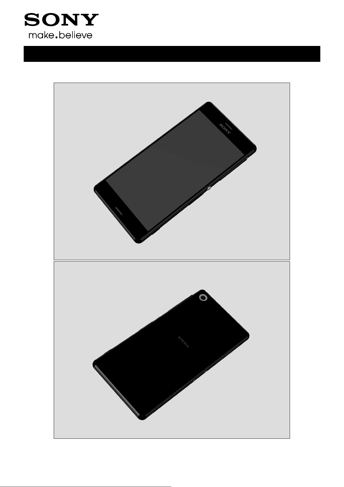
1 Exterior Views
1.1 D6633, L55u & L50t
Working Instructions (mech)
1291-7738 Rev 1
© Sony Mobile Communications AB – Company Internal
4(86)
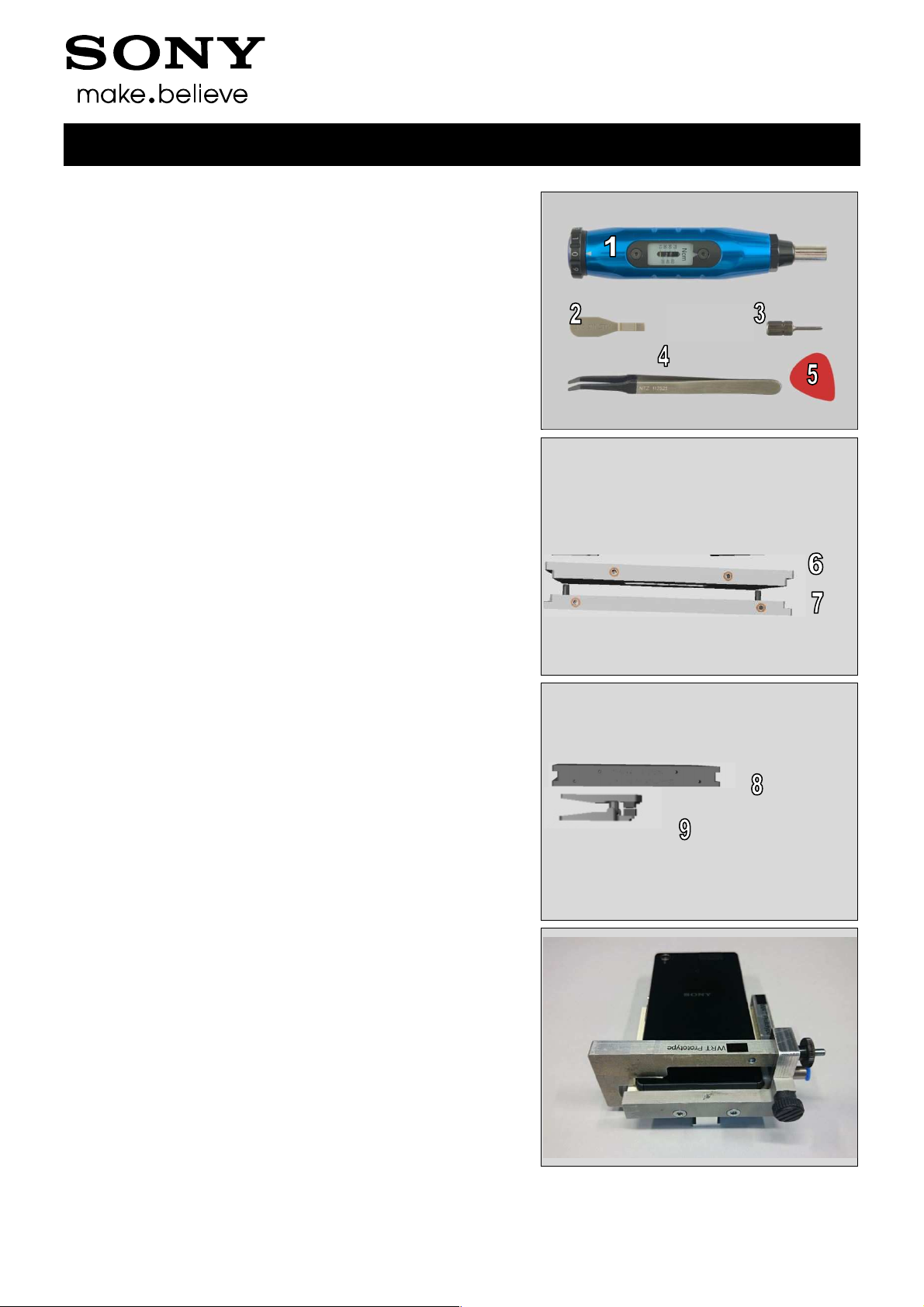
2 Tools
SPECIAL TOOLS
1. Torque Screwdriver
2. Front Opening Tool
3. Bits (JCIS No 0)
4. Flex Film Assembly Tool
5. Guitar Pick
6. Rear Panel Press Top Inlay(1287-4891)
7. Bottom Press Inlay(1287-4890)
Working Instructions (mech)
8. Rear Panel Adhesive alignment fixture(1287-4892)
9. Audio Jack Press(1287-4893)
10. WRT Inlay Plate(1287-4895)
1291-7738 Rev 1
© Sony Mobile Communications AB – Company Internal
5(86)
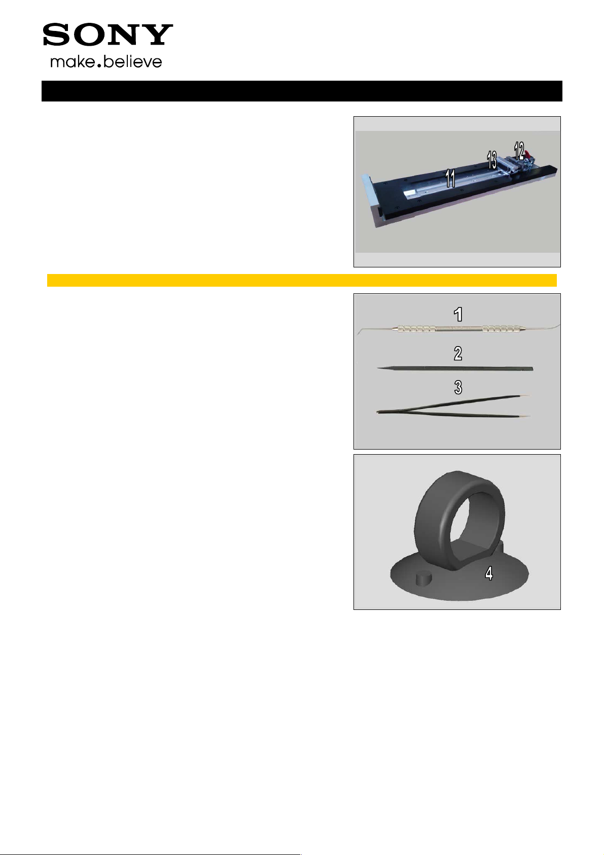
Tools
11. Side Panel press
12. Side Panel Press Head
13. Charge connector press pad
For part no’s on the tools above, refer to the ‘Tools Catalogue/Matrix’.
STANDARD TOOLS
1. Dentist Hook
2. Nylon Pointer
3. Tweezers
Working Instructions (mech)
4. Suction Cup
1291-7738 Rev 1
© Sony Mobile Communications AB – Company Internal
6(86)
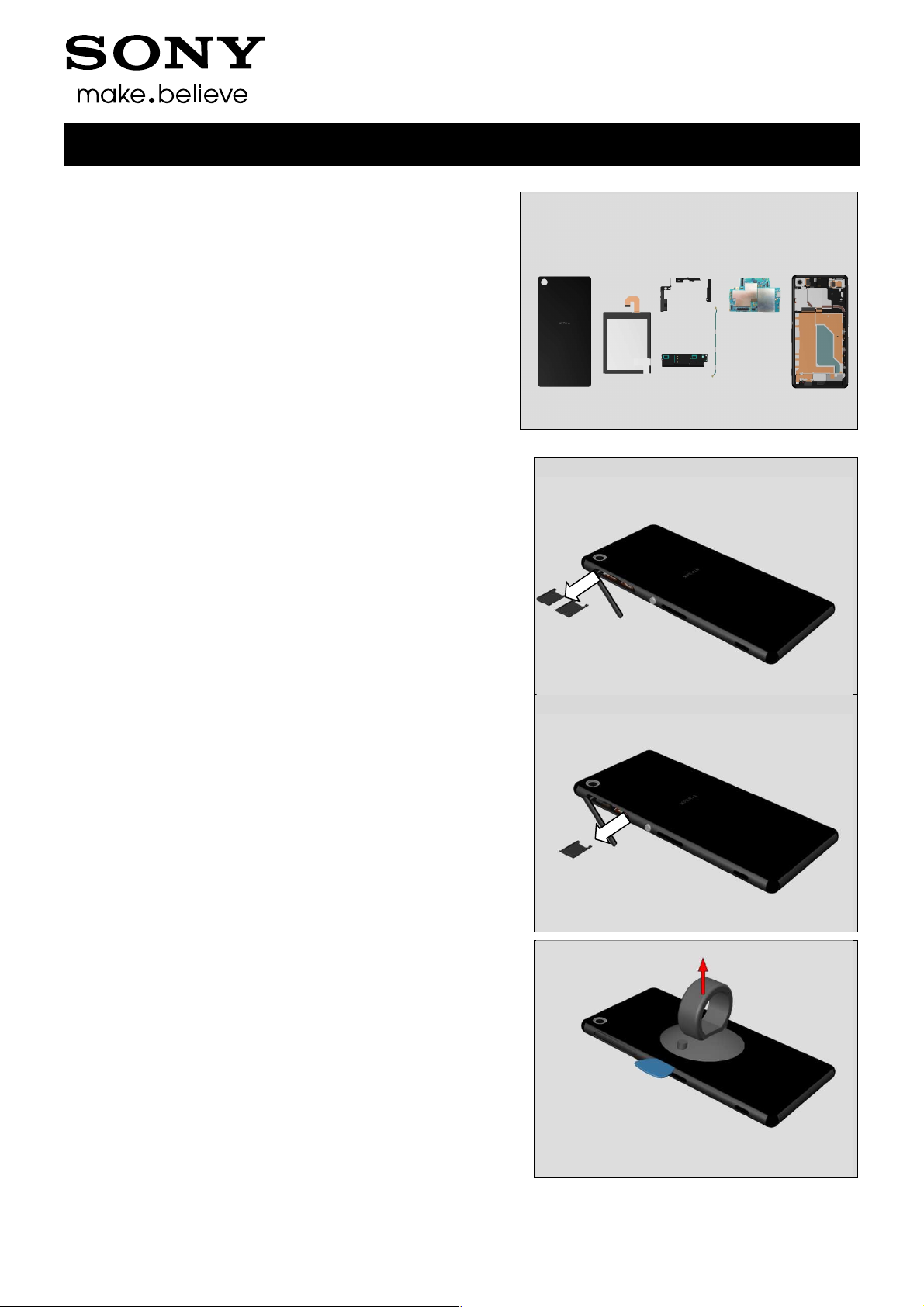
3 Disassembly
The disassembly is done in the following order:
1. Rear Panel
2. Embedded Battery
3. Cover Holder –A(a), Sub Antenna(b), Antenna BT +
WLAN(c)
4. Holder Speaker sub assembly
5. Main PBA
6. Front Assy
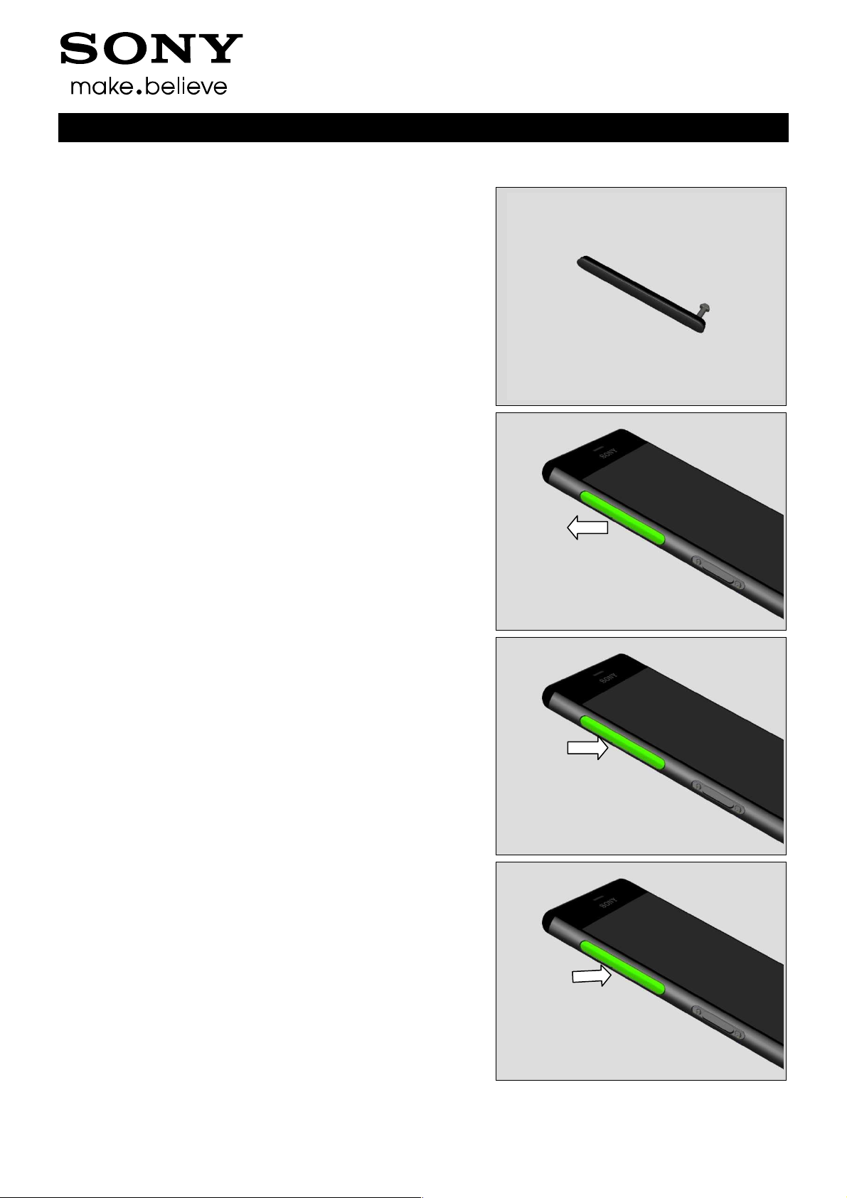
3.1 Rear Panel
Open the Cap SIM and remove the SIM Tray (Two SIM
Tray for D6633, L55u).
Then Close the Cap SIM.
Working Instructions (mech)
3b
3a
3c
5
1
2
4
6
Open the Cap SIM and remove the SIM Tray (One SIM
Tray for L55t).
Then Close the Cap SIM.
Attach the Suction cup, insert the Guitar Pick.
1291-7738 Rev 1
© Sony Mobile Communications AB – Company Internal
7(86)
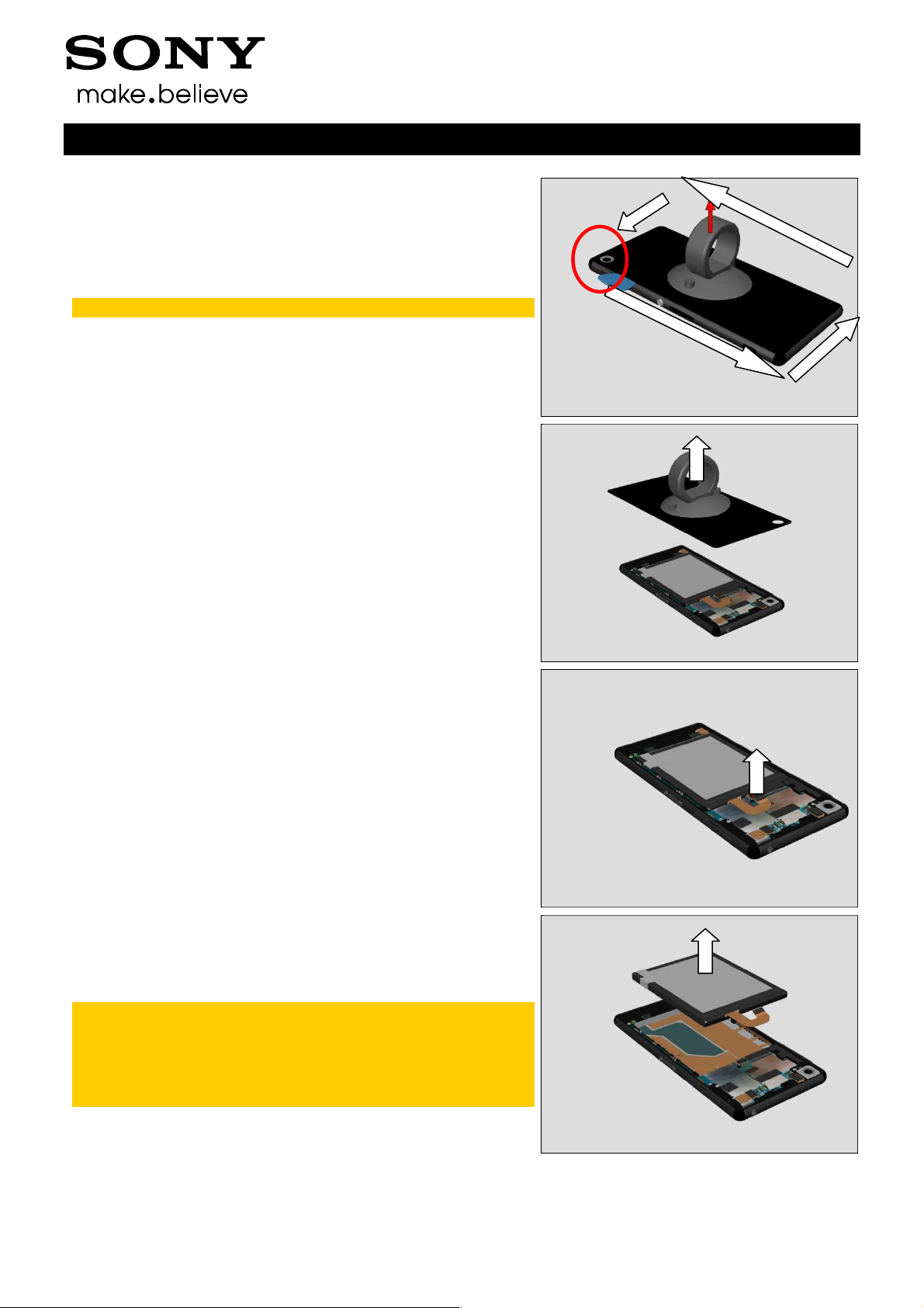
Disassembly
Slide along all sides.
Note: Do not slide Camera corner area.
Remove the Rear Panel.
Working Instructions (mech)
3.2 Embedded Battery
Unsnap the BtB connector of the Embedded Battery.
Lift up the Embedded Battery at an angel and remove the
Embedded Battery.
Note: the Film part of Adhesive Battery Front maybe
peeled off together with Embedded Battery.
Embedded Battery together with the film part of
Adhesive Battery Front could be reused if not damaged.
1291-7738 Rev 1
© Sony Mobile Communications AB – Company Internal
8(86)
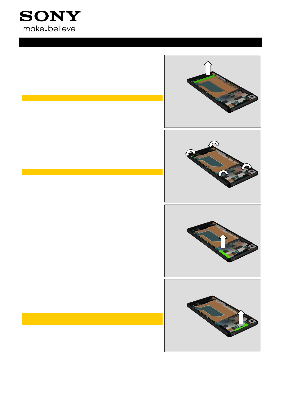
Disassembly
Remove the Cushion Battery.
Scrap! Not to be reused.
Remove the four Screws by using a screwdriver with
Bits (JCIS No 0).
Scrap! Not to be reused.
Working Instructions (mech)
3.3 Cover Holder –A, Sub
Antenna, Antenna BT +
WLAN
Remove the Cover Holder –A from Main PBA.
Remove the Sub Antenna from Main PBA.
Note: be careful about the hooks of Sub Antenna
avoiding being damaged!
1291-7738 Rev 1
© Sony Mobile Communications AB – Company Internal
9(86)
Disassembly
Remove the Antenna BT + WLAN from Main PBA.
Open two RF connectors and Remove the RF Cable from its
cavity.
Working Instructions (mech)
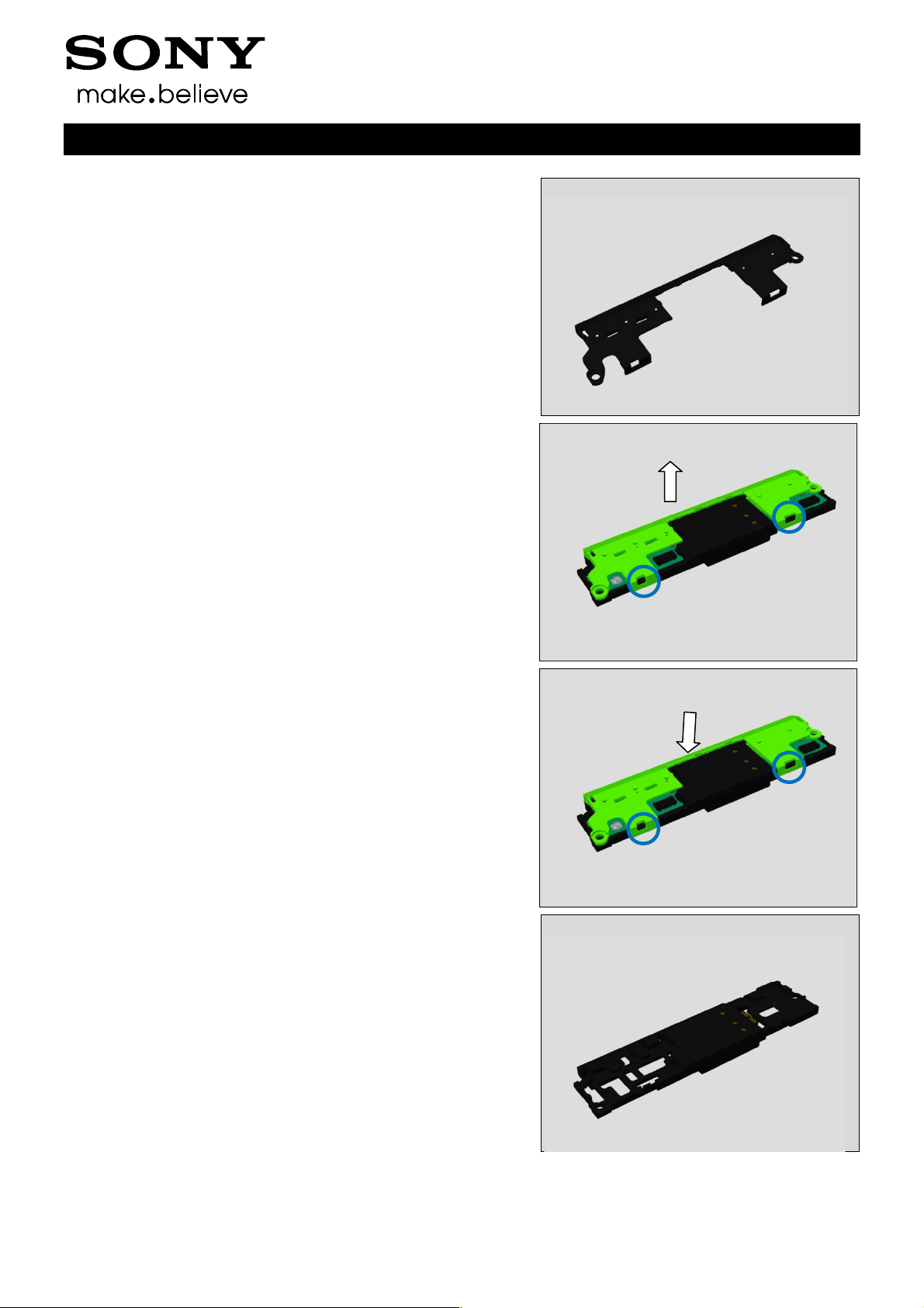
3.4 Holder Speaker sub
assembly
Unsnap the BtB connector from Sub PBA-B as shown.
Insert Front Opening Tool to release vibrator’s hook from
Front Assy.
1291-7738 Rev 1
© Sony Mobile Communications AB – Company Internal
10(86)

Disassembly
Turn over the vibrator FPC.
Unsnap the BtB connector from Sub PBA-A as shown.
Working Instructions (mech)
Insert Guitar Pick under Holder Speaker sub assembly as
shown to lift its bottom side up.
Remove the Holder Speaker sub assembly from Front Assy.
1291-7738 Rev 1
© Sony Mobile Communications AB – Company Internal
11(86)
Disassembly
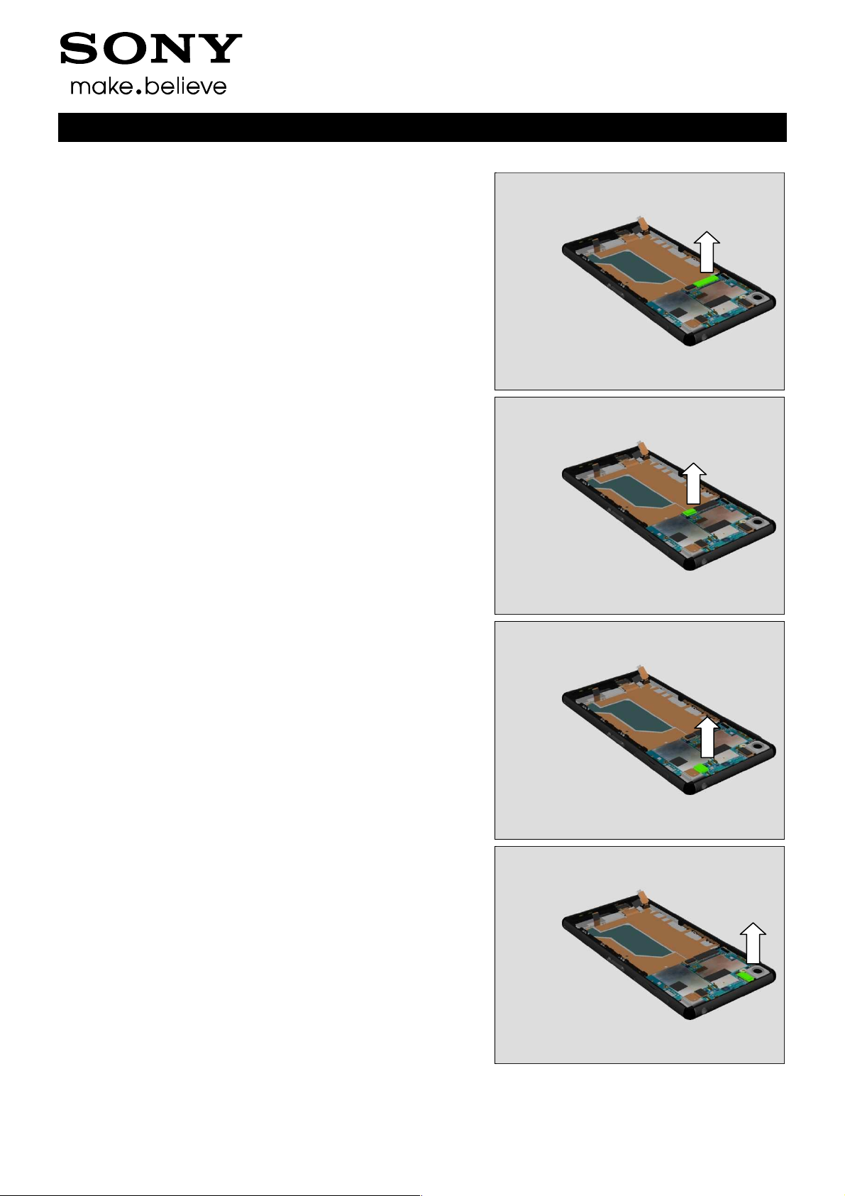
3.5 Main PBA
Unsnap the BtB connector of Relay FPC PBA.
Working Instructions (mech)
Unsnap the BtB connector of Charge FPC.
Unsnap the BtB connector of Audio Jack.
Unsnap the BtB connector of Main Camera.
1291-7738 Rev 1
© Sony Mobile Communications AB – Company Internal
12(86)
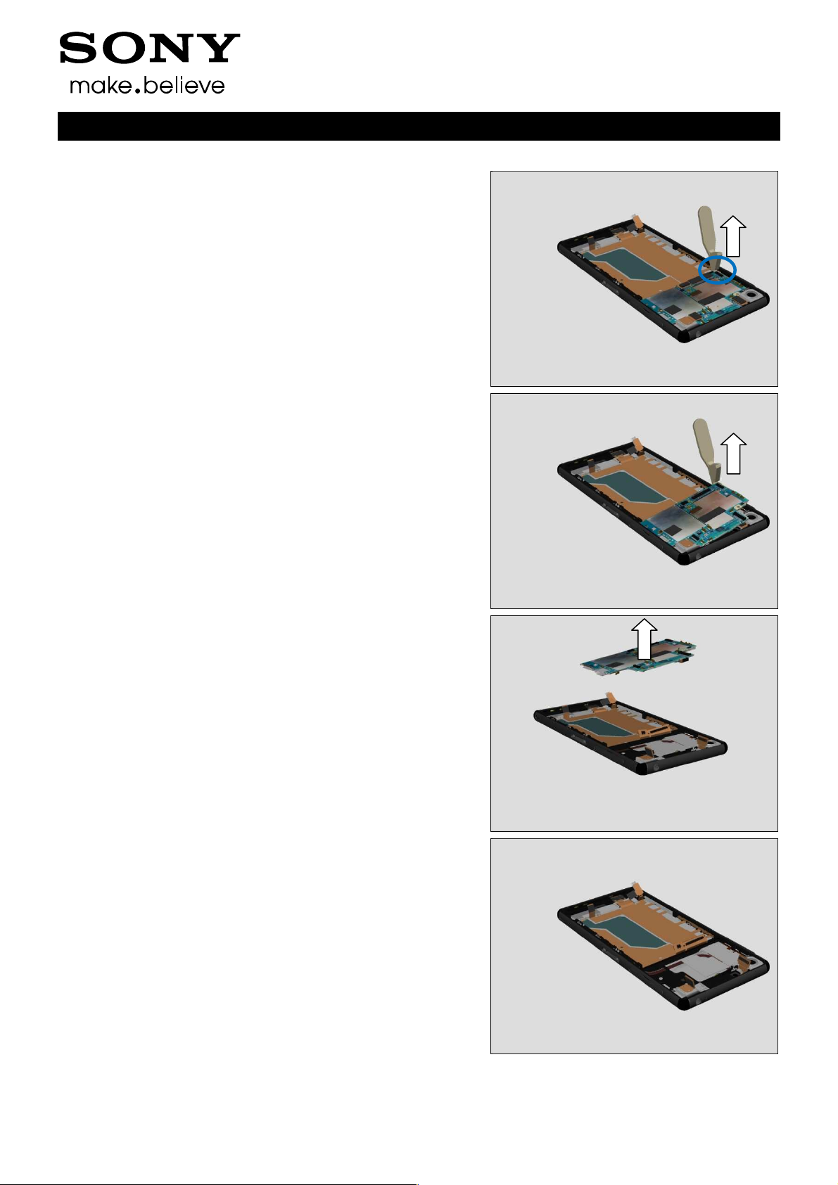
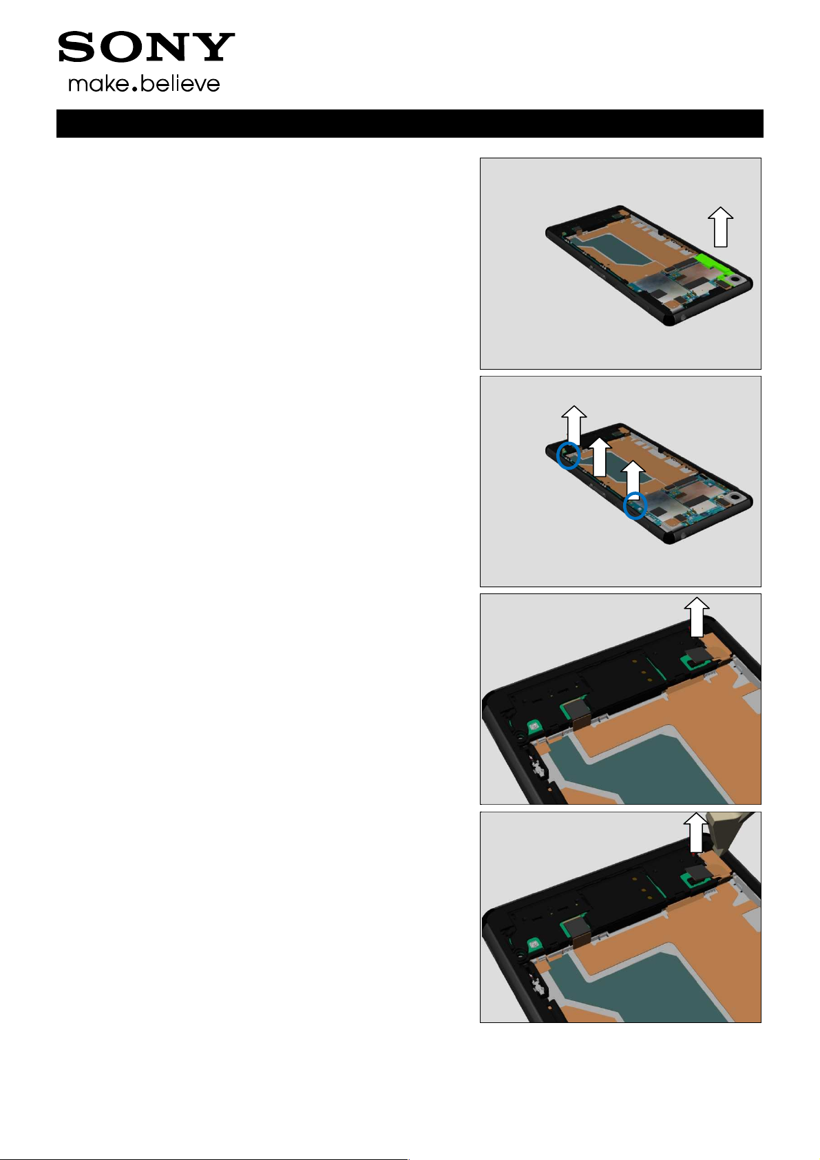
Disassembly
Insert the Front Opening Tool to release the Main PBA’s
hook.
Working Instructions (mech)
Lift up the main PBA.
Remove the Main PBA from the Front Assy.
Front Assy as shown.
1291-7738 Rev 1
© Sony Mobile Communications AB – Company Internal
3.6 Front Assy
13(86)
4 Replacement
4.1 SIM Tray
Follow the 3.1 Disassembly instructions!
Prepare the new SIM Tray.
Follow the 5.6 Reassembly instructions!
Note: D6633, L55u have two SIM Trays.
L55t has only one SIM Tray.
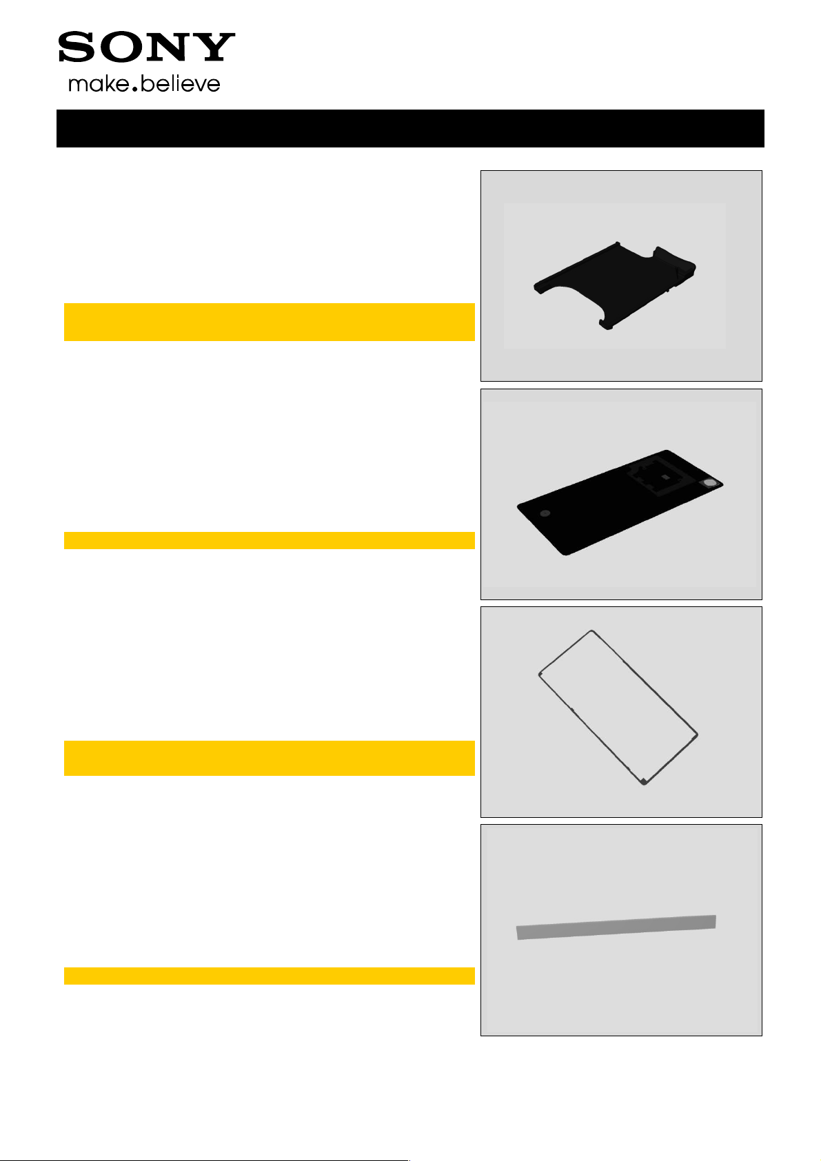
4.2 Rear Panel
Follow the 3.1 Disassembly instructions!
Prepare the new Rear Panel.
Follow the 5.6 Reassembly instructions!
Note: New Rear Panel already has Adhesive Rear Panel.
Working Instructions (mech)
4.3 Adhesive Rear Panel
Follow the 3.1 Disassembly instructions!
Prepare the new Adhesive Rear Panel.
Follow the 5.6 Reassembly instructions!
Note: old Adhesive Rear Panel could not be reused.
Scrap!
4.4 Cushion Battery
Follow the 3.1 – 3.2 Disassembly instructions!
Prepare the new Cushion Battery.
Follow the 5.5 – 5.6 Reassembly instructions!
Scrap! Not to be reused.
1291-7738 Rev 1
© Sony Mobile Communications AB – Company Internal
14(86)

1
2
1
2
Replacement
4.5 Embedded Battery
Follow the 3.1 – 3.2 Disassembly instructions!
Prepare the new Embedded Battery.
Follow 4.48 4.31 Installation instructions.
Follow the 5.5 – 5.6 Reassembly instructions!
Note: Must use new Adhesive Battery Front.
Visual Inspection of Emedded Battery.
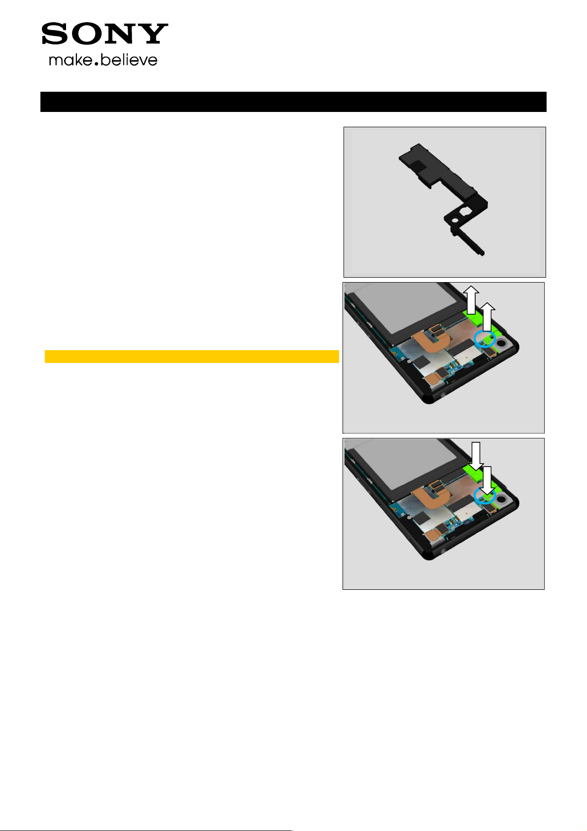
4.6 Cover Holder -A
Follow the 3.1 Disassembly instructions!
Carry out the Removal as described below.
Prepare the new Cover Holder -A.
Carry out the Installation as described below.
Follow the 5.6 Reassembly instructions!
Working Instructions (mech)
REMOVAL
Remove the Screw by using a screwdriver with Bits (JCIS
No 0).
Scrap! Not to be reused.
Remove Cover Holder –A from Main PBA.
INSTALLATION
Assemble new Cover Holder –A at its correct position as
shown.
Apply 12 ± 1 Ncm torque when tightening the Screw
Bits (JCIS No 0).
1291-7738 Rev 1
© Sony Mobile Communications AB – Company Internal
15(86)
Replacement
4.7 Sub Antenna
Follow the 3.1 Disassembly instructions!
Carry out the Removal as described below.
Prepare the new Sub Antenna.
Carry out the Installation as described below.
Follow the 5.6 Reassembly instructions!
Working Instructions (mech)
REMOVAL
Remove the Sub Antenna from Main PBA.
INSTALLATION
Assemble Sheet Sub Antenna on new Sub Antenna (2
pieces) as shown.
Assemble new Sub Antenna onto Main PBA.
Press to secure its hooks is properly assembled.
1291-7738 Rev 1
© Sony Mobile Communications AB – Company Internal
16(86)
1
2
1
2
Replacement
4.8 Antenna BT + WLAN
Follow the 3.1 Disassembly instructions!
Carry out the Removal as described below.
Prepare the new Antenna BT + WLAN.
Carry out the Installation as described below
Follow the 5.6 Reassembly instructions!
Working Instructions (mech)
REMOVAL
Remove the Screw by using a screwdriver with Bits (JCIS
No 0).
Scrap! Not to be reused.
Remove Antenna BT + WLAN from Main PBA.
INSTALLATION
Assemble Antenna BT + WLAN on Main PBA.
Apply 12 ± 1 Ncm torque when tightening the Screw
Bits (JCIS No 0).
1291-7738 Rev 1
© Sony Mobile Communications AB – Company Internal
17(86)
Replacement
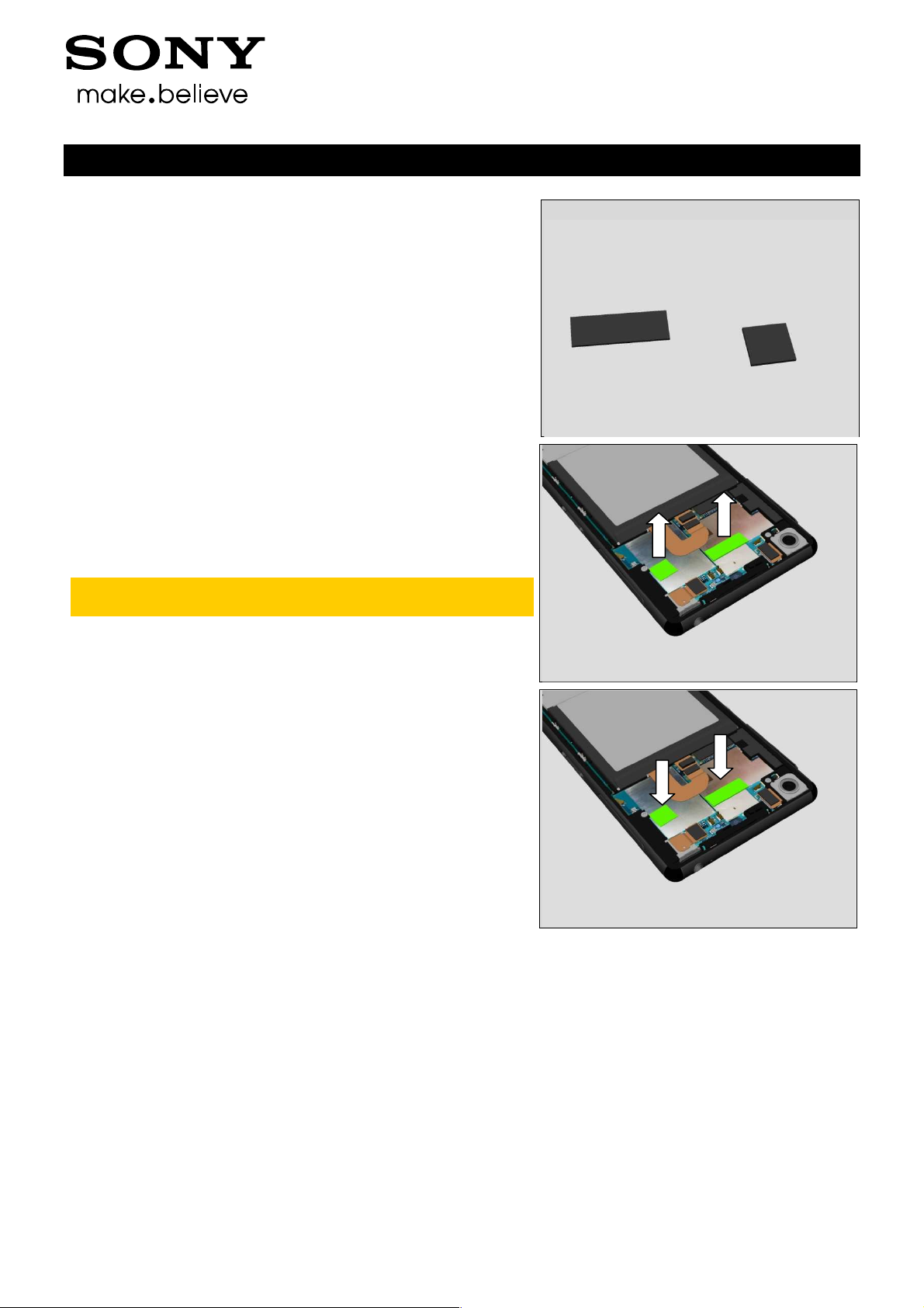
4.9 Sheet ACO L & Sheet
ACO R
Follow the 3.1 Disassembly instructions!
Carry out the Removal as described below.
Prepare the new Sheet ACO L(a) & Sheet ACO R(b).
Carry out the Installation as described below
Follow the 5.6 Reassembly instructions!
REMOVAL
Remove the Sheet ACO L & Sheet ACO R from Main PBA.
Note: Clean surplus of Sheet ACO L & Sheet ACO R
from Rear Panel if has.
Working Instructions (mech)
a
b
INSTALLATION
Assemble new Sheet ACO L & Sheet ACO R on Main PBA
at their correct position as shown.
1291-7738 Rev 1
© Sony Mobile Communications AB – Company Internal
18(86)
Replacement
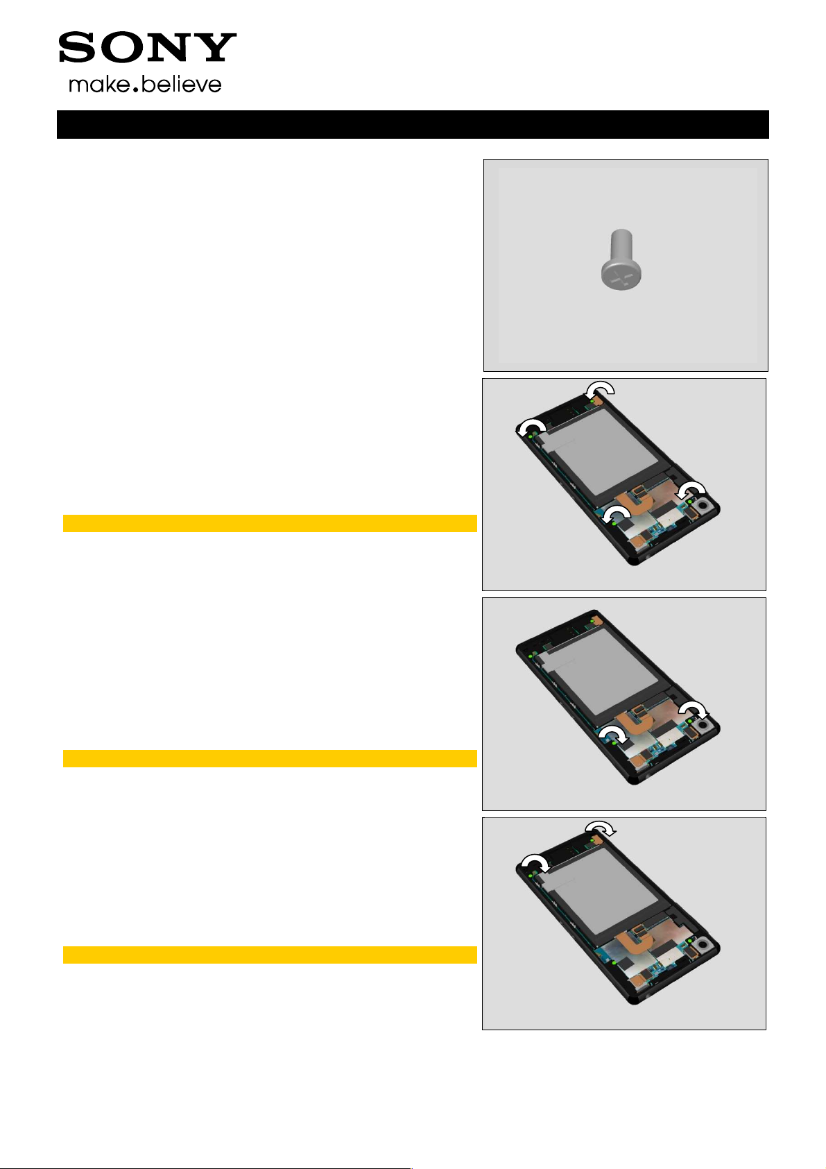
4.10 Screw M14×3.3
Follow the 3.1 Disassembly instructions!
Carry out the Removal as described below.
Prepare the new Screw M14×3.3.
Carry out the Installation as described below
Follow the 5.6 Reassembly instructions!
REMOVAL
Remove the four Screws by using a screwdriver with
Bits (JCIS No 0).
Scrap! Not to be reused.
Working Instructions (mech)
INSTALLATION
Apply 12 ± 1 Ncm torque on Main PBA when tightening the
Screw Bits (JCIS No 0).
Take new Screws!
Apply 8 ± 1 Ncm torque on Holder Speaker sub assembly
when tightening the Screw Bits (JCIS No 0).
Take new Screws!
1291-7738 Rev 1
© Sony Mobile Communications AB – Company Internal
19(86)
Replacement
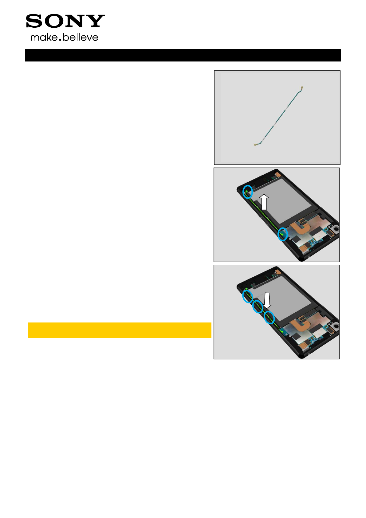
4.11 RF Cable
Follow the 3.1 Disassembly instructions!
Carry out the Removal as described below.
Prepare the new RF Cable.
Carry out the Installation as described below
Follow the 5.6 Reassembly instructions!
Working Instructions (mech)
REMOVAL
Open two RF connectors and remove the RF Cable from its
cavity.
INSTALLATION
Assemble RF Cable into its cavity and connect two RF
connectors.
Note: the RF Cable has direction. The long Metal side is
towards Main PBA.
1291-7738 Rev 1
© Sony Mobile Communications AB – Company Internal
20(86)
Replacement
4.12 Main Antenna
Follow the 3.1 – 3.4 Disassembly instructions!
Carry out the Removal as described below.
Prepare the new Main Antenna.
Carry out the Installation as described below
Follow the 5.3 – 5.6 Reassembly instructions!
REMOVAL
Open two hooks and remove the Main Antenna from Holder
Speaker sub assembly.
Working Instructions (mech)
INSTALLATION
Assemble the Main Antenna onto Holder Speaker sub
assembly.
Press to secure its hooks is properly assembled.
4.13 Holder Speaker sub
assembly
Follow the 3.1 – 3.4 Disassembly instructions!
Follow 4.12, 4.14, 4.15, 4.29 Removal instructions.
Prepare the new Holder Speaker sub assembly.
Follow 4.12, 4.14, 4.15, 4.29 Installation instructions.
Follow the 5.3 – 5.6 Reassembly instructions!
1291-7738 Rev 1
© Sony Mobile Communications AB – Company Internal
21(86)

Replacement
4.14 Sub PBA-A & Sheet
Sub PBA
Follow the 3.1 – 3.4 Disassembly instructions!
Follow 4.12 Removal instructions.
Carry out the Removal as described below.
Prepare the new Sub PBA-A and new Sheet Sub PBA.
Carry out the Installation as described below.
Follow 4.12 Installation instructions.
Follow the 5.3 – 5.6 Reassembly instructions!
REMOVAL
Remove the Sub PBA-A from Holder Speaker sub assembly.
Working Instructions (mech)
INSTALLATION
Place new Sub PBA-A on Holder Speaker sub assembly.
Press to secure its hooks is properly assembled.
Place new Sheet Sub PBA to cover Sub PBA-A IC.
1291-7738 Rev 1
© Sony Mobile Communications AB – Company Internal
22(86)
© Sony Mobile Communications AB
Replacement
B
Disassembly instructions!
as described below.
as described below
Follow 4.12 Installation instructions.
Reassembly instructions!
Holder Spea
Holder Speaker sub assembly
is properly
Film Display BtB
Disassembly instructions!
as described below.
as described below
Reassembly instructions!
Working Instructions (mech)
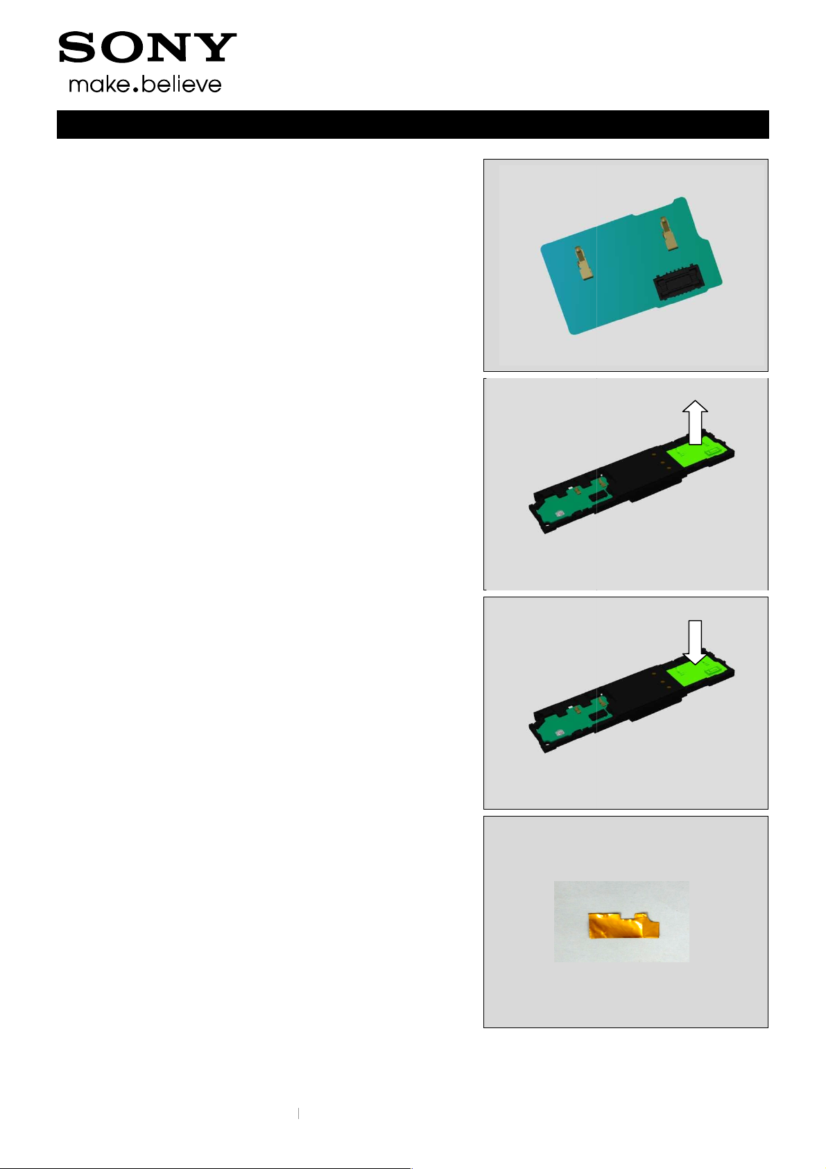
4.15 Sub PBA-
Follow the 3.1 – 3.4
Follow 4.12 Removal instructions.
Carry out the Removal
Prepare the new Sub PBA-B.
Carry out the Installation
Follow the 5.3 – 5.6
REMOVAL
Remove the Sub PBA-B from
.
ker sub assembly.
INSTALLATION
Place new Sub PBA-B on
Press to secure its hooks
4.16
Follow the 3.1 – 3.4
Carry out the Removal
Prepare the new Film Display BtB.
Carry out the Installation
Follow the 5.3 – 5.6
assembled.
.
.
1291-7738 Rev 1
– Company Internal
23(86)
Replacement
REMOVAL
Remove the Film Display BtB from Plate holder speaker.
INSTALLATION
Place new Film Display BtB on Plate holder speaker.
Working Instructions (mech)
4.17 Front Assy
Follow the 3.1 – 3.6 Disassembly instructions!
Follow the 4.16, 4.23, 4.24, 4.25, 4.26, 4.30, 4.33, 4.34,
4.35, 4.38, 4.39, 4.47(L55t only), 4.49, 4.48
Removal instructions!
Carry out the Removal as described below.
Prepare the new Front Assy.
Carry out the Installation as described below.
Follow the 4.23, 4.24, 4.25, 4.26, 4.30, 4.33, 4.34, 4.35,
4.38, 4.39, 4.47(L55t only), 4.37, 4.41, 4.42, 4.22, 4.16,
4.43, 4.46, 4.21, 4.49, 4.48 Installation instructions!
Follow the 5.1 – 5.6 Reassembly instructions!
1291-7738 Rev 1
© Sony Mobile Communications AB – Company Internal
24(86)
© Sony Mobile Communications AB
Sub Camera
Disassembly instructions!
as described below.
described
Reassembly instructions!
Open the connector and remove the
on Sub Camera first as
ched on two sides of
Insert ZIF connector first and lock it down.
on Main PBA.
Working Instructions (mech)
& Sheet Chat Camera
ched on two sides of
Replacement
4.18
Follow the 3.1 – 3.6
Carry out the Removal
Prepare the new Camera Chat.
Carry out the Installation as
Follow the 5.1 – 5.6
REMOVAL
Chat Camera.
below.
Sub Camera & Sheet
INSTALLATION
Attach new Sheet Chat Camera
shown.
Note: Sheet Chat Camera is atta
Sub Camera as shown.
Put Sub Camera into its cavity
1291-7738 Rev 1
– Company Internal
25(86)
Replacement
4.19 Cap USB
Carry out the Removal as described below.
Prepare the new Cap USB.
Carry out the Installation as described below.
Working Instructions (mech)
REMOVAL
Remove the Cap USB, Pull its tail out.
INSTALLATION
Insert the new Cap USB tail first into its hole, and then push
it back into phone.
Press to secure its position.
1291-7738 Rev 1
© Sony Mobile Communications AB – Company Internal
26(86)

Replacement
4.20 Cap SIM
Carry out the Removal as described below.
Prepare the new Cap SIM.
Carry out the Installation as described below.
Working Instructions (mech)
REMOVAL
Remove the Cap USB, Pull its tail out.
INSTALLATION
Insert the new Cap USB tail first into its hole, then push it
back into phone.
Press to secure its position.
1291-7738 Rev 1
© Sony Mobile Communications AB – Company Internal
27(86)

Replacement
4.21 Core Unit Label
Carry out the Removal as described below.
Prepare the new Core Unit Label.
Carry out the Installation as described below.
Note: D6633, L55u Core Unit Label includes two piece of
White Paper.
L55t Core Unit Label has only one piece of White Paper.
Working Instructions (mech)
REMOVAL
Read the old Core Unit Label and write the information
into the ‘’LabelPrint Solution’ program.
Open the Cap SIM and pull out the Label Tray using Dentist
Hook.
Remove the Core Unit Label.
Scrap Core Unit Label, not to be reused.
Remove and clean any remaining adhesive residue found
on Label Tray.
INSTALLATION
Check that the proper label format is loaded in the Zebra
printer and write a new Label by using the ‘Label Print’
software.
Place and align a new Core Unit Label in the correct
position. Press with a finger to secure the attachment.
One label only is allowed.
1291-7738 Rev 1
© Sony Mobile Communications AB – Company Internal
28(86)

Replacement
4.22 Gore Sheet(1st mic)
Follow the 3.1 – 3.4 Disassembly instructions!
Carry out the Removal as described below.
Prepare the new Gore Sheet(1st mic).
Carry out the Installation as described below.
Follow the 5.3 – 5.6 Reassembly instructions!
REMOVAL
Turn over the Main MIC FPC from its cavity first.
Remove the Gore Sheet(1st mic) from Front Assy.
Clean the surplus adhesive on Holder Mic sub assembly.
Working Instructions (mech)
INSTALLATION
Place New Gore Sheet(1st mic) in its cavity on Front Assy.
Turn over the Main MIC FPC back and assemble it into its
cavity.
Press to secure its attachment.
1291-7738 Rev 1
© Sony Mobile Communications AB – Company Internal
29(86)

Working Instructions (mech)
Replacement
4.23 Loudspeaker B & Grill Receiver Black
Follow the 3.1 – 3.6 Disassembly instructions!
Follow 4.38 Removal Instructions.
Carry out the Removal as described below.
Prepare the new Loudspeaker B and Grill Receiver Black.
Carry out the Installation as described below.
Follow 4.38 Installation Instructions.
Follow the 5.1 – 5.6 Reassembly instructions!
REMOVAL
Remove the Loudspeaker B from its cavity.
Remove the old Grill Receiver Black from its cavity.
Scrap! Not to be reused!
INSTALLATION
Place new Grill Receiver Black into its cavity.
1291-7738 Rev 1
© Sony Mobile Communications AB – Company Internal
30(86)

Replacement:
Place the new Loudspeaker B into its cavity as shown in the
picture.
Do not touch the pins of the Loudspeaker B!
Press the Loudspeaker B to secure the attachment.
Working Instructions (mech)
Do not touch the pins of the Loudspeaker B!
1291-7738 Rev 1
© Sony Mobile Communications AB – Company Internal
31(86)

Working Instructions (mech)
Replacement
4.24 Audio Jack & Cushion Audio Jack FPC BtB
Follow the 3.1 – 3.6 Disassembly instructions!
Carry out the Removal as described below.
Prepare the new Audio Jack and new Cushion Audio Jack
FPC BtB.
Carry out the Installation as described below.
Follow the 5.1 – 5.6 Reassembly instructions!
Note: New Audio Jack already has Adhesive WP Audio
Jack.
REMOVAL
Remove the Audio Jack and Cushion Audio Jack FPC BtB
gently from its cavity.
Clean the old Adhesive and all remaining of the Adhesive
residue found in the cavity.
INSTALLATION
Place new Cushion Audio Jack FPC BtB on Audio Jack FPC
BtB connector gently.
1291-7738 Rev 1
© Sony Mobile Communications AB – Company Internal
32(86)

© Sony Mobile Communications AB
lready has
Assemble Audio Jack into its Cavity on Front Assy.
fixture to press Audio Jack.
Working Instructions (mech)
Replacement:
Prepare the new Audio Jack.
Note: New Audio Jack a
Jack.
Adhesive WP Audio
Use the Audio Jack Press
Place the unit in the fixture.
1291-7738 Rev 1
– Company Internal
33(86)

© Sony Mobile Communications AB
Replacement:
Audio Jack Pres
MIC FPC area back on Audio Jack
MIC FPC area on Audio Jack at its correct
Note: Check front camera and Proximity/Light Sensor
Working Instructions (mech)
Press for ten seconds with the
secure the attachment.
Bend 2nd
s to
as shown.
Assemble 2nd
position.
position from Phone front side.
1291-7738 Rev 1
– Company Internal
34(86)

Working Instructions (mech)
Replacement
4.25 Charge FPC & Adhesive Charge FPC
Follow the 3.1 – 3.2 Disassembly instructions!
Carry out the Removal as described below.
Prepare the new Charge FPC & Adhesive Charge FPC.
Carry out the Installation as described below.
Follow 4.31 Installation instructions.
Follow the 5.5 – 5.6 Reassembly instructions!
Visual Inspektion of the Charge FPC.
REMOVAL
Unsnap the BtB connector of Charge FPC.
Lift the Charge FPC up to release the adhesive.
There are three hooks for Charger FPC.
1291-7738 Rev 1
© Sony Mobile Communications AB – Company Internal
35(86)

Replacement
Detach the Charge FPC from Front Assy using Front
Opening Tool.
Lift up the Charge FPC vertically as shown.
Working Instructions (mech)
Note: there is a guide pillar on Front Assy.
Release the guide pillar and Remove the Charge FPC from
Front Assy.
1291-7738 Rev 1
© Sony Mobile Communications AB – Company Internal
36(86)

Replacement:
Clean the surplus Adhesive Charge FPC from Front Assy.
Working Instructions (mech)
INSTALLATION
Place new Adhesive Charge FPC on Front Assy.
Place new Cushion Battery FPC BtB on the BtB connector
of new Charger FPC.
Place new Charge FPC onto Front Assy.
1291-7738 Rev 1
© Sony Mobile Communications AB – Company Internal
37(86)

Replacement:
Assemble the guide pillar first as shown.
Working Instructions (mech)
Put down Charger FPC on Front Assy.
Press this side area to ensure its hooks is properly
assembled.
Press the Charge FPC area to secure its attachment.
1291-7738 Rev 1
© Sony Mobile Communications AB – Company Internal
38(86)

Replacement:
Connect the BtB connector on Main PBA.
Working Instructions (mech)
1291-7738 Rev 1
© Sony Mobile Communications AB – Company Internal
39(86)

Working Instructions (mech)
Replacement
4.26 Relay FPC PBA &Adhesive Relay FPC A &Adhesive
Relay FPC B
Follow the 3.1 – 3.4 Disassembly instructions!
Follow the 4.16, 4.39, 4.22 Removal instructions!
Carry out the Removal as described below.
Prepare the new Relay FPC PBA, Adhesive Relay FPC A
and Adhesive Relay FPC B.
Carry out the Installation as described below.
Follow the 4.16, 4.39, 4.27, 4.22, 4.28 Installation
instructions!
Follow the 5.3 – 5.6 Reassembly instructions!
Visual Inspection of the Relay FPC.
B
A
REMOVAL
Unsnap the BtB between the Relay FPC PBA and Main
PBA.
Disassemble the main MIC FPC area from Front Assy.
Unsnap the BtB between the Relay FPC PBA and LCM
FPC.
Disassemble the FPC area from Front Assy.
1291-7738 Rev 1
© Sony Mobile Communications AB – Company Internal
40(86)

Replacement:
Release the camera key holder area from Front Assy.
Release the volume/power key FPC area from Front Assy.
Working Instructions (mech)
Remove the Relay FPC PBA From Front Assy.
Note: if the Relay FPC PBA is damaged, Do not reuse it
then, scrap.
Clean the Adhesive Relay FPC A from Front Assy.
Scrap! Cannot be reused.
1291-7738 Rev 1
© Sony Mobile Communications AB – Company Internal
41(86)

Replacement:
Clean the Adhesive Relay FPC B from Front Assy.
Scrap! Cannot be reused.
INSTALLATION
Place a new Adhesive Relay FPC B on Front Assy
Working Instructions (mech)
Place a new Adhesive Relay FPC A on Front Assy
Prepare new Relay FPC PBA on Front Assy.
1291-7738 Rev 1
© Sony Mobile Communications AB – Company Internal
42(86)

Replacement:
Assemble the camera key holder area on Front Assy first.
Assemble the volume/power key FPC area on Front Assy.
Working Instructions (mech)
Put down the FPC area on Front Assy.
Press to secure its attachment.
Assemble the main MIC FPC area on Front Assy.
Connect the BtB between the Relay FPC PBA and LCM
FPC.
Note: Must new Gore Sheet(1st mic) on Front Assy and
new Holder Mic sub assembly on Relay FPC PBA.
1291-7738 Rev 1
© Sony Mobile Communications AB – Company Internal
43(86)

Replacement:
Connect the BtB connector between the Relay FPC PBA
and Main PBA.
Working Instructions (mech)
1291-7738 Rev 1
© Sony Mobile Communications AB – Company Internal
44(86)

© Sony Mobile Communications AB
Replacement
Mic sub assembly
Disassembly instructions!
as described below.
Holder Mic sub assembl
as described below
Reassembly instructions!
Disassemble the main MIC FPC area from Front Assy.
Unsnap the BtB between the Relay FPC PBA and LCM
ssembly
damage the Relay FPC PBA.
Holder Mic sub assembly
Do not damage the Relay FPC PBA.
Working Instructions (mech)
4.27 Holder
Follow the 3.1 – 3.4
Carry out the Removal
Prepare the new
Carry out the Installation
Follow the 5.3 – 5.6
REMOVAL
FPC.
y.
.
Remove the Holder Mic sub a
FPC PBA.
Scrap! Cannot be reused.
Do not
INSTALLATION
Place new
Press to secure its attachment.
gently from Relay
on main MIC.
1291-7738 Rev 1
– Company Internal
45(86)

Replacement
Connect the BtB between the Relay FPC PBA and LCM
FPC.
Assemble the main MIC FPC area on Front Assy.
Press to secure its attachment,
Working Instructions (mech)
1291-7738 Rev 1
© Sony Mobile Communications AB – Company Internal
46(86)

Working Instructions (mech)
Replacement
4.28 Cushion Relay FPC BtB & Cushion Relay FPC
bottom BtB & Cushion 10pin BB speaker
Follow the 3.1 Disassembly instructions!
Carry out the Removal as described below.
Prepare the new Cushion Relay FPC BtB(a), Cushion Relay
FPC bottom BtB(b) and Cushion 10pin BB speaker(c.).
Carry out the Installation as described below.
Follow the 5.6 Reassembly instructions!
REMOVAL
Remove the Cushion Relay FPC BtB(a), Cushion Relay
FPC bottom BtB(b) and Cushion 10pin BB speaker(c.) from
Relay FPC PBA.
Scrap! Cannot be reused.
a
b
c
a
b
c
INSTALLATION
Assemble new Cushion Relay FPC BtB(a), Cushion Relay
FPC bottom BtB(b) and Cushion 10pin BB speaker(c) onto
Relay FPC PBA at its correct BtB connector.
a
b
c
1291-7738 Rev 1
© Sony Mobile Communications AB – Company Internal
47(86)

Replacement
4.29 Cushion MIC
Follow the 3.1 – 3.4 Disassembly instructions!
Carry out the Removal as described below.
Prepare the new Cushion MIC.
Carry out the Installation as described below.
Follow the 5.3 – 5.6 Reassembly instructions!
REMOVAL
Remove the Cushion MIC from Holder Speaker sub
assembly.
Working Instructions (mech)
INSTALLATION
Place new Cushion MIC on Holder Speaker sub assembly.
1291-7738 Rev 1
© Sony Mobile Communications AB – Company Internal
48(86)

Replacement
4.30 Plate holder speaker
Follow the 3.1 – 3.4 Disassembly instructions!
Carry out the Removal as described below.
Prepare the new Plate Speaker.
Carry out the Installation as described below.
Follow the 5.3 – 5.6 Reassembly instructions!
Working Instructions (mech)
REMOVAL
Release the Film Display BtB.
Disassemble the main MIC area from Front Assy.
Open the BtB connector.
1291-7738 Rev 1
© Sony Mobile Communications AB – Company Internal
49(86)

Replacement:
Remove the Plate holder speaker.
Remove the Gore Sheet(1st mic) from Front Assy.
Remove the surplus adhesive from Holder Mic sub
assembly also.
Working Instructions (mech)
INSTALLATION
Place new Gore Sheet(1st mic) at its cavity.
Assemble the Plate holder speaker at its position.
1291-7738 Rev 1
© Sony Mobile Communications AB – Company Internal
50(86)

Replacement:
Connect the BtB connector.
Assemble the Main MIC area onto its cavity.
Press to secure its attachment.
Working Instructions (mech)
Assemble the new Film Display BtB on Plate holder
speaker.
1291-7738 Rev 1
© Sony Mobile Communications AB – Company Internal
51(86)

Replacement
4.31 Cushion Battery FPC BtB
Follow the 3.1 Disassembly instructions!
Prepare the new Cushion Battery FPC BtB
Carry out the Installation as described below.
Follow the 5.6 Reassembly instructions!
REMOVAL
Remove the Cushion Battery FPC BtB(2 pcs).
Scrap! Cannot be reused.
Working Instructions (mech)
INSTALLATION
Prepare the new Cushion Battery FPC BtB(2pcs) at their
correct BtB connectors.
1291-7738 Rev 1
© Sony Mobile Communications AB – Company Internal
52(86)

Replacement
4.32 Cushion Rear Panel
Follow the 3.1 Disassembly instructions!
Carry out the Removal as described below.
Prepare the new Cushion Rear Panel.
Carry out the Installation as described below.
Follow the 5.6 Reassembly instructions!
REMOVAL
Remove the Cushion Rear Panel from Rear Panel.
Scrap! Cannot be reused.
Working Instructions (mech)
INSTALLATION
Assemble the new Cushion Rear Panel on Rear Panel.
1291-7738 Rev 1
© Sony Mobile Communications AB – Company Internal
53(86)

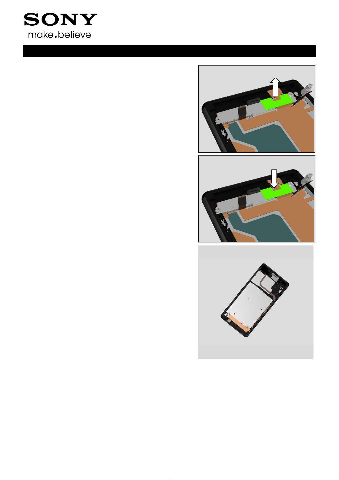
Replacement
4.33 Shield Main Camera
Follow the 3.1 Disassembly instructions!
Follow 4.34 Removal Instructions.
Carry out the Removal as described below.
Prepare the new Shield Main Camera.
Carry out the Installation as described below
Follow 4.34 Installation Instruction..
Follow the 5.6Reassembly instructions!
REMOVAL
Remove the Shield Main Camera from its cavity.
Working Instructions (mech)
INSTALLATION
Place the new Shield Main Camera into its cavity.
Press with your finger to secure the position.
1291-7738 Rev 1
© Sony Mobile Communications AB – Company Internal
54(86)

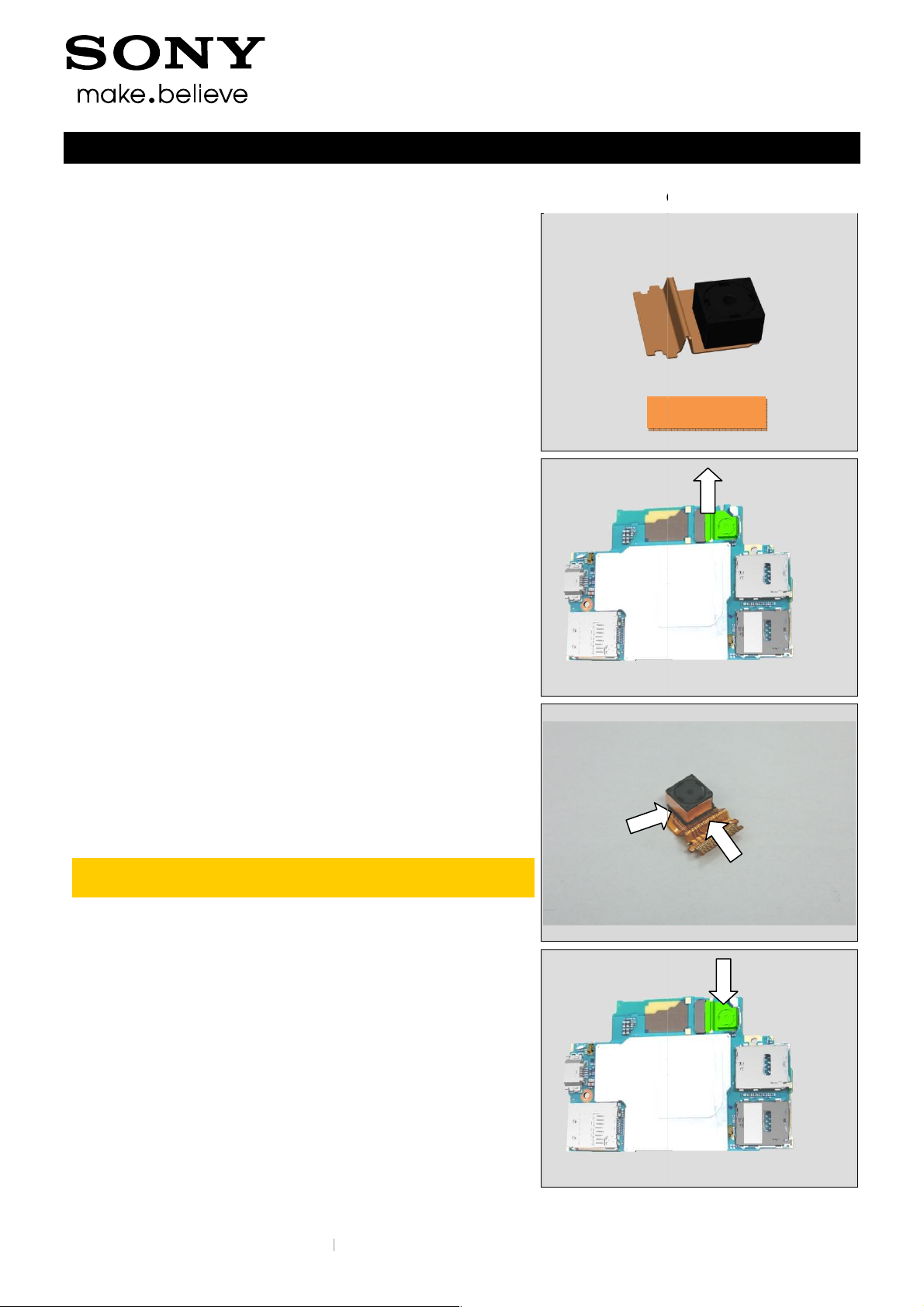
Working Instructions (mech)
Replacement
4.34 Main Camera & Cushion Camera BtB
Follow the 3.1 Disassembly instructions!
Follow 4.8 Removal instructions.
Carry out the Removal as described below.
Prepare the new Main Camera & Cushion Camera BtB.
Carry out the Installation as described below.
Follow 4.8 Installation instructions.
Follow the 5.6 Reassembly instructions!
REMOVAL
Remove the Main Camera and Cushion Camera BtB.
INSTALLATION
Place Main Camera into its Cavity first.
Connect its BtB connector onto Main PBA.
Assemble the new Cushion Camera BtB.
1291-7738 Rev 1
© Sony Mobile Communications AB – Company Internal
55(86)

Replacement
4.35 Label tray
Follow the 3.1 – 3.6 Disassembly instructions!
Follow the 4.21, 4.37 Removal instructions!
Carry out the Removal as described below.
Prepare the new Label tray.
Carry out the Installation as described below.
Follow the 4.21, 4.37 Installation instructions!
Follow the 5.1 – 5.6 Reassembly instructions!
REMOVAL
Remove the Label tray (D6633, L55u) from Front Assy.
Working Instructions (mech)
D6633, L55u
L55t
Remove the Label tray (L55t) from Front Assy.
INSTALLATION
Assemble the Label tray (D6633, L55u) on Front Assy.
1291-7738 Rev 1
© Sony Mobile Communications AB – Company Internal
56(86)

Replacement
Assemble the Label tray (L55t) on Front Assy.
Working Instructions (mech)
1291-7738 Rev 1
© Sony Mobile Communications AB – Company Internal
57(86)

Replacement
4.36 Liquid indicator
Follow the 3.1 – 3.6 Disassembly instructions!
Carry out the Removal as described below.
Prepare the new Liquid indicator.
Carry out the Installation as described below.
Follow the 5.1 – 5.6 Reassembly instructions!
REMOVAL
Remove the Liquid indicator from Front Assy.
Scrap! Cannot be reused.
Liquid indicator (b) is attached on vertical side.
Working Instructions (mech)
a
b
INSTALLATION
Align and press to attach new Liquid indicator on Front Assy.
Liquid indicator (b) is attached on vertical side.
a
b
1291-7738 Rev 1
© Sony Mobile Communications AB – Company Internal
58(86)

© Sony Mobile Communications AB
Replacement
Label Guide
Disassembly instructions!
as described below.
as described below
Reassembly instructions!
(D6633, L55u)
from Front Assy
(D6633, L55u)
Working Instructions (mech)
4.37
Follow the 3.1 – 3.6
Carry out the Removal
Prepare the new Label Guide.
Carry out the Installation
Follow the 5.1 – 5.6
REMOVAL
Remove the Label Guide
Scrap! Cannot be reused.
.
from Front Assy.
D6633, L55u
L55t
Remove the Label Guide (L55t)
Scrap! Cannot be reused.
INSTALLATION
Place new Label Guide
.
on Front Assy.
1291-7738 Rev 1
– Company Internal
59(86)

© Sony Mobile Communications AB
Place new Label Guide (L55t) on Front Assy.
Working Instructions (mech)
Replacement
1291-7738 Rev 1
– Company Internal
60(86)

Replacement
4.38 Holder Receiver sub assembly
Follow the 3.1 – 3.6 Disassembly instructions!
Carry out the Removal as described below.
Prepare the new Holder Receiver sub assembly.
Carry out the Installation as described below.
Follow the 5.1 – 5.6Reassembly instructions!
REMOVAL
Remove the Holder Receiver sub assembly from its cavity.
Working Instructions (mech)
INSTALLATION
Place a new Holder Receiver sub assembly into its cavity
1291-7738 Rev 1
© Sony Mobile Communications AB – Company Internal
61(86)

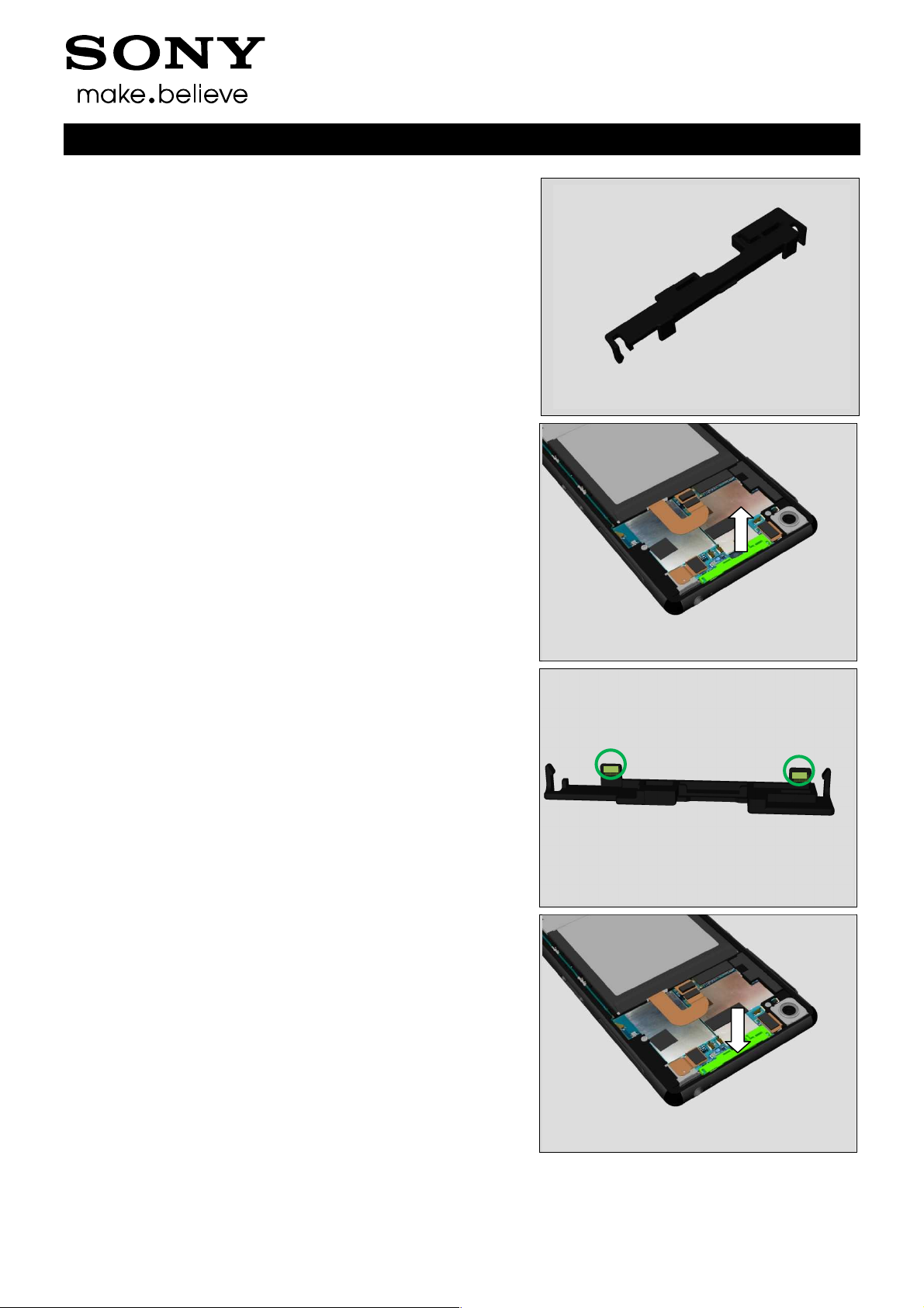
Replacement
4.39 Holder key volume
Follow the 3.1 – 3.6 Disassembly instructions!
Carry out the Removal as described below.
Prepare the new Holder key volume.
Carry out the Installation as described below.
Follow the 5.1 – 5.6Reassembly instructions!
REMOVAL
Push the Holder key volume as shown direction to release
its hooks first.
Working Instructions (mech)
Remove the Holder key volume from Front Assy.
INSTALLATION
Assemble the Holder key volume from left side as shown.
1291-7738 Rev 1
© Sony Mobile Communications AB – Company Internal
62(86)

Replacement
Then push the Holder key volume to right side as shown to
lock its hooks.
Working Instructions (mech)
1291-7738 Rev 1
© Sony Mobile Communications AB – Company Internal
63(86)

Replacement
4.40 Magnetic connector
Carry out the Removal as described below.
Prepare the new Magnetic connector.
Carry out the Installation as described below.
REMOVAL
Remove the Magnetic connector from phone.
Scrap! Cannot be reused.
Clean the surplus adhesive left on its cavity.
Working Instructions (mech)
INSTALLATION
Place the new Magnetic connector onto its cavity.
Press to secure the attachment.
Then use Side Panel press, Side Panel Press Head and
Charge connector press pad with the force of 60N for five
Seconds. According to 1003-9107 Tool Catalogue –
mechanical and document Side Panel press Instruction for
Use.
Note: Use the pressing fixture of Charge connector
press pad (1275-4443) to press it.
1291-7738 Rev 1
© Sony Mobile Communications AB – Company Internal
64(86)

Replacement
4.41 Gasket conductive USB
Follow the 3.1 – 3.4 Disassembly instructions!
Carry out the Removal as described below.
Prepare the new Gasket conductive USB.
Carry out the Installation as described below.
Follow the 5.5 – 5.8 Reassembly instructions!
REMOVAL
Remove the Gasket conductive USB from Front Assy.
Scrap! Cannot be reused.
Working Instructions (mech)
INSTALLATION
Attach new Gasket conductive USB on Front Assy.
1291-7738 Rev 1
© Sony Mobile Communications AB – Company Internal
65(86)

Replacement
4.42 Gasket speaker rubber
Follow the 3.1 – 3.4 Disassembly instructions!
Carry out the Removal as described below.
Prepare the new Gasket speaker rubber.
Carry out the Installation as described below.
Follow the 5.3 – 5.6 Reassembly instructions!
REMOVAL
Remove the Gasket speaker rubber from its cavity.
Scrap! Cannot be reused.
Working Instructions (mech)
INSTALLATION
Place the Gasket speaker rubber into its cavity.
Press to secure its attachment.
1291-7738 Rev 1
© Sony Mobile Communications AB – Company Internal
66(86)

Replacement
4.43 Cushion Chat Camera
Follow the 3.1 – 3.6 Disassembly instructions!
Carry out the Removal as described below.
Prepare the Cushion Chat Camera.
Carry out the Installation as described below.
Follow the 5.1 – 5.6 Reassembly instructions!
REMOVAL
Remove the Cushion Chat Camera from its cavity.
Scrap! Cannot be reused.
Working Instructions (mech)
INSTALLATION
Assemble the new Cushion Chat Camera into its cavity.
1291-7738 Rev 1
© Sony Mobile Communications AB – Company Internal
67(86)

Replacement
4.44 Sheet Sub PBA
Follow the 3.1 – 3.6 Disassembly instructions!
Carry out the Removal as described below.
Prepare the Sheet Sub PBA.
Carry out the Installation as described below.
Follow the 5.1 – 5.6 Reassembly instructions!
REMOVAL
Remove the Sheet Sub PBA from Sub PBA-A IC.
Scrap! Cannot be reused.
Working Instructions (mech)
INSTALLATION
Assemble the new Sheet Sub PBA on Sub PBA-A IC.
1291-7738 Rev 1
© Sony Mobile Communications AB – Company Internal
68(86)

Replacement
4.45 Sheet Sub ANT
Follow the 3.1 – 3.6 Disassembly instructions!
Carry out the Removal as described below.
Prepare the Sheet Sub ANT.
Carry out the Installation as described below.
Follow the 5.1 – 5.6 Reassembly instructions!
Working Instructions (mech)
REMOVAL
Remove the Sheet Sub ANT from Sub Antenna.
Scrap! Cannot be reused.
INSTALLATION
Assemble the new Sheet Sub ANT on Sub Antenna.
1291-7738 Rev 1
© Sony Mobile Communications AB – Company Internal
69(86)

Replacement
4.46 Film for TP FPC
Follow the 3.1 – 3.6 Disassembly instructions!
Carry out the Removal as described below.
Prepare the Film for TP FPC.
Carry out the Installation as described below.
Follow the 5.1 – 5.6 Reassembly instructions!
Working Instructions (mech)
REMOVAL
Remove the Film for TP FPC from Front Assy.
Scrap! Cannot be reused.
INSTALLATION
Assemble the new Film for TP FPC on Front Assy.
1291-7738 Rev 1
© Sony Mobile Communications AB – Company Internal
70(86)

Replacement
4.47 Dummy SIM assy (L55t only)
Follow the 3.1 – 3.6 Disassembly instructions!
Carry out the Removal as described below.
Prepare the Dummy SIM assy.
Carry out the Installation as described below.
Follow the 5.1 – 5.6 Reassembly instructions!
REMOVAL
Push the Dummy SIM assy out as shown.
Remove the Dummy SIM assy
Note: Only L55t has this Dummy SIM assy.
Working Instructions (mech)
INSTALLATION
Insert the new Dummy SIM assy as shown.
Use the Label Guide gap as shown to fix its position
1291-7738 Rev 1
© Sony Mobile Communications AB – Company Internal
71(86)

Replacement
Working Instructions (mech)
4.48
Follow the 3.1 – 3.2 Disassembly instructions!
Carry out the Removal as described below.
Prepare the Adhesive Battery Front.
Carry out the Installation as described below.
Follow the 5.5 – 5.6 Reassembly instructions!
REMOVAL
Remove the old Adhesive Battery Front left on Front Assy.
Note: old Adhesive Battery Front left on Front Assy
cannot be reused. Scrap!
If the film part of Adhesive Battery Front is left on
Embedded Battery without damage, this film part on
Embedded Battery could be reused together with
Embedded Battery.
Adhesive Battery Front
INSTALLATION
Assemble the new Adhesive Battery Front on Front Assy.
1291-7738 Rev 1
© Sony Mobile Communications AB – Company Internal
72(86)

Replacement:
Working Instructions (mech)
4.49
Follow the 3.1 – 3.6 Disassembly instructions!
Follow 4.24 Removal instructions.
Carry out the Removal as described below.
Prepare the Adhesive WP Audio Jack.
Carry out the Installation as described below.
Follow 4.24 Installation instructions.
Follow the 5.1 – 5.6 Reassembly instructions!
REMOVAL
Remove the old Adhesive WP Audio Jack from Audio Jack.
Note: Scrap! Cannot be reused.
Adhesive WP Audio Jack
INSTALLATION
Assemble new Adhesive WP Audio Jack on Audio Jack.
1291-7738 Rev 1
© Sony Mobile Communications AB – Company Internal
73(86)

Replacement
4.50 Board Swap - Replacement
Follow the 3.1 – 3.6 Disassembly instructions!
Follow the 4.18 Removal instructions!
Replace the Swap Board.
Reuse the Main Camera and the Camera Chat.
Follow the 4.18 Installation instructions!
Follow the 5.1 – 5.6 Reassembly instructions!
Press the On/Off key to power on the unit, place unit on
flat desk and wait 4 minutes until system boot up has
been completed.
Please DO NOT move the unit during the start up until
“Select Language” menu is shown on the display!
Working Instructions (mech)
After “Select Language” menu, turn off the unit.
Follow the calibrations in Trouble Shooting Application
1262-6643 – mechanical
Accelerometer
Gyroscope
Noise cancelling
1291-7738 Rev 1
© Sony Mobile Communications AB – Company Internal
74(86)

© Sony Mobile Communications AB
Replacement
Board Swap
Follow the instructions in the Generic Repair Manual
Board Swap
Follow the instructions in the Generic Repair Manual
swap for customization of the software.
Working Instructions (mech)
Software
4.51
CHANGE LABEL
Build swap for change of label.
4.52
– Change Label
–
– Customize of
CUSTOMIZE OF SOFTWARE
Build
–
1291-7738 Rev 1
– Company Internal
75(86)

5 Reassembly
1. Front Assy
2. Main PBA
3. Holder Speaker sub assembly
4. Cover Holder –A(a), Sub Antenna(b), Antenna BT
+ WLAN(c)
5. Embedded Battery
6. Rear Panel
6
Working Instructions (mech)
4b
4a
4c
2
5
3
1
5.1 Front Assy
Prepare the Front Assy.
5.2 Main PBA
Place the Main PBA into Front Assy.
Align with the USB connector first.
Note: Pls make sure that all FPC BtB connectors are
above Main PBA.
Put down Main PBA gently to secure the position.
1291-7738 Rev 1
© Sony Mobile Communications AB – Company Internal
76(86)

Reassembly
Make sure the Hook is is properly assembled.
Connect all the four the BtB connectors on Main PBA.
Working Instructions (mech)
5.3 Holder Speaker sub
assembly
Place the Holder Speaker sub assembly onto Front Assy.
Insert the top side of Holder Speaker sub assembly into
Front Assy first.
1291-7738 Rev 1
© Sony Mobile Communications AB – Company Internal
77(86)

Reassembly
Put down the Bottom side of Holder Speaker sub assembly
then.
Press to secure its position.
Connect the BtB connector of the Relay FPC PBA.
Working Instructions (mech)
Turn over the vibrator FPC and press it to secure its
position.
Connect the BtB connector of the Holder Speaker sub
assembly.
1291-7738 Rev 1
© Sony Mobile Communications AB – Company Internal
78(86)

Reassembly
5.4 Cover Holder –A, Sub
Antenna, Antenna BT +
WLAN
Place the RF Cable back, Connect and press both two RF
connectors.
Note: RF Cable has direction. The long metal side is
towards Main PBA.
,
Insert RF Cable into its cavity.
Note: RF Cable has direction. The long metal side is
towards Main PBA.
Working Instructions (mech)
,
Place the the Antenna BT + WLAN on Main PBA.
,
Place the the Sub Antenna on Main PBA.
Note: Ensure the Sheet Sub Ant(2 pieces) are already
attached on Sun Antenna.
1291-7738 Rev 1
© Sony Mobile Communications AB – Company Internal
79(86)

Reassembly
Place the the Cover Holder –A on Main PBA.
,
Apply 12 ± 1 Ncm torque on Main PBA when tightening the
Screw Bits (JCIS No 0).
Working Instructions (mech)
Take new Screws!
,
Apply 8 ± 1 Ncm torque on Holder Speaker sub assembly
when tightening the Screw Bits (JCIS No 0).
Take new Screws!
,
Assemble the Cushion Battery at its correct position.
1291-7738 Rev 1
© Sony Mobile Communications AB – Company Internal
80(86)

Reassembly
5.5 Embedded Battery
Note: Visible inspection of the Embedded Battery.
There is risk to damage the cell laminate (Pinhole,
Bubbles or Wrinkles) when the Adhesive Battery Front
is removed.
If the Embedded Battery is damaged, then It cannot be
reused.
,
The film part of Adhesive Battery Front on Embedded
Battery could be reused if it is not damaged.
Working Instructions (mech)
,
Remove the old Adhesive Battery Front left on Front assy.
,
Attach the new Adhesive Battery Front on Front assy.
Note: if the film part of Adhesive Battery Front on
Embedded Battery could be reused, then need to
remove the new film part on Front assy.
1291-7738 Rev 1
© Sony Mobile Communications AB – Company Internal
81(86)

Reassembly
Place the Embedded Battery into its cavity.
Connector the BtB connectors on Main PBA.
,
Working Instructions (mech)
Press gently with your finger on the Embedded Battery to
secure the attachment.
,
Remove the old Sheet ACO L and Sheet ACO R from Main
PBA.
Note: Clean Rear Panel if there are some surplus
adhesive left on Rear Panel.
,
Place new Sheet ACO L and Sheet ACO R on Main PBA.
1291-7738 Rev 1
© Sony Mobile Communications AB – Company Internal
82(86)

Reassembly
5.6 Rea Panel
Remove the old Adhesive Rear Panel and all remaining of
the Adhesive residue.
Clean the edges of the Rear Panel carefully with alcohol
before the new Adhesive Panel Back is mounted. This
action is done to secure the water resistant of the unit.
Place the new Adhesive Rear Panel in the Rear Panel
adhesive alignment fixture and the Rear Panel in a correct
Position.
Working Instructions (mech)
Press to secure the attachment.
The Rear Panel is ready to be assembled.
,
1291-7738 Rev 1
© Sony Mobile Communications AB – Company Internal
83(86)

Reassembly
Place the Rear Panel on Core Unit at its correct position.
Use Isopropyl Alcohol - 99 % for clean around the edges
of Front Assy before assembly Rear Panel.
,
Press with fingers first to secure its attachment
Working Instructions (mech)
Upper inlay = Rear Panel Press Top Inlay
Lower inlay = Bottom Press Inlay
Place the phone in the Bottom Press Inlay and follow the
instruction in 1003-9107 Tool Catalogue – mechanical and
document Toothed Rack Press Instruction for use.
Insert the Bottom Press Inlay with Phone.
1291-7738 Rev 1
© Sony Mobile Communications AB – Company Internal
84(86)

Reassembly
Press with 494 ± 60 N for 10 seconds
(the pressure value is adjusted for 600N because of the
weight of the pressure fixture)
Remove the unit from the pressure fixture.
Working Instructions (mech)
,
Insert SIM Tray into its cavity and close the Cap SIM.
Note:
1. Pay more attention about SIM tray direction.
2. D6633, L55u have two SIM Trays. L55t has one SIM
Tray.
1291-7738 Rev 1
© Sony Mobile Communications AB – Company Internal
85(86)

Rev.
Date
Changes / Comments
6 Revision History
1 2014-09-12 Initial release
Working Instructions (mech)
1291-7738 Rev 1
© Sony Mobile Communications AB – Company Internal
86(86)
 Loading...