

Working Instructions
- mechanical -
Xperia
D6603,D6616,D6643,D6653
1288-9438 Rev 2
© Sony Mobile Communications AB – Company Internal
TM
Z3

Working Instructions (mech)
CONTENTS
1 Exterior Views ................................................................................. 6
1.1 D6603, D6616, D6643, D6653 ................................................................ 6
2 Tools ................................................................................................ 7
3 Disassembly.................................................................................... 9
3.1 Sim Tray ................................................................................................. 9
3.2 Rear Panel ............................................................................................ 10
3.3 Sub Antenna ........................................................................................ 11
3.4 Holder Main Camera ............................................................................ 12
3.5 Main Camera ........................................................................................ 12
3.6 Antenna BT + WLAN ........................................................................... 13
3.7 Main PBA .............................................................................................. 13
3.8 Shield Main Camera ............................................................................ 15
3.9 Audio Jack ........................................................................................... 15
3.10 RF cable ............................................................................................... 16
3.11 Embedded Battery ............................................................................... 16
3.12 Cushion Battery ................................................................................... 16
3.13 Main Antenna ....................................................................................... 17
3.14 Holder Vibrator .................................................................................... 18
3.15 Plate Speaker ....................................................................................... 19
3.16 Holder Speaker sub assembly ........................................................... 19
3.17 Charge FPC .......................................................................................... 20
3.18 Holder key volume .............................................................................. 21
3.19 Plate holder speaker ........................................................................... 22
3.20 Relay FPC + Front Assy ...................................................................... 22
4 Replacement ................................................................................. 23
4.1 Sim Tray ............................................................................................... 23
4.2 Rear Panel ............................................................................................ 23
4.3 Sub Antenna ........................................................................................ 23
4.4 Holder Main Camera ............................................................................ 23
4.5 Main Camera ........................................................................................ 24
4.6 Antenna BT + WLAN ........................................................................... 24
4.7 Main PBA .............................................................................................. 24
4.8 Shield Main Camera ............................................................................ 24
4.9 Audio Jack ........................................................................................... 25
4.10 RF cable ............................................................................................... 25
4.11 Embedded Battery ............................................................................... 25
4.12 Cushion Battery ................................................................................... 25
4.13 Main Antenna ....................................................................................... 26
4.14 Holder Vibrator .................................................................................... 26
1288-9438 Rev 2
© Sony Mobile Communications AB – Company Internal 2(97)

Working Instructions (mech)
4.15 Plate Speaker ....................................................................................... 26
4.16 Holder Speaker sub assembly ........................................................... 26
4.17 Charge FPC .......................................................................................... 27
4.18 Holder key volume .............................................................................. 27
4.19 Plate holder speaker ........................................................................... 27
4.20 Relay FPC ............................................................................................. 27
4.21 Front Assy ............................................................................................ 28
4.22 Adhesive Battery Front ....................................................................... 29
4.23 Adhesive Battery Rear ........................................................................ 30
4.24 Adhesive Battery Rear 2 ..................................................................... 31
4.25 Adhesive Charger FPC ....................................................................... 32
4.26 Adhesive FPC Speaker ....................................................................... 33
4.27 Adhesive Rear Panel ........................................................................... 34
4.28 Adhesive Relay FPC A ........................................................................ 35
4.29 Adhesive Relay FPC B ........................................................................ 36
4.30 Adhesive WP Audio Jack ................................................................... 37
4.31 Adhesive WP holder speaker ............................................................. 38
4.32 Adhesive WP Speaker ......................................................................... 39
4.33 Cap SD .................................................................................................. 40
4.34 Cap USB ............................................................................................... 41
4.35 Core Unit Label .................................................................................... 42
4.36 Cushion Audio Jack FPC BtB ............................................................ 43
4.37 Cushion Battery FPC BtB ................................................................... 44
4.38 Cushion Camera BtB .......................................................................... 45
4.39 Cushion Chat Camera ......................................................................... 46
4.40 Cushion Rear Panel ............................................................................ 47
4.41 Cushion Relay FPC bottom BtB ......................................................... 48
4.42 Cushion Relay FPC BtB ...................................................................... 49
4.43 Cushion Speaker ................................................................................. 50
4.44 Cushion Vibrator ................................................................................. 51
4.45 Gasket conductive USB ...................................................................... 52
4.46 Gore Sheet(1st mic) .............................................................................. 53
4.47 Grill Receiver ....................................................................................... 54
4.48 Holder Mic sub assembly ................................................................... 55
4.49 Holder Receiver sub assembly .......................................................... 56
4.50 Label Plate ........................................................................................... 57
4.51 Label Plate Guide ................................................................................ 58
4.52 Lightguide 3 LED ................................................................................. 59
4.53 Liquid Indicator ................................................................................... 60
4.54 Loudspeaker ........................................................................................ 61
4.55 Loudspeaker B .................................................................................... 62
1288-9438 Rev 2
© Sony Mobile Communications AB – Company Internal 3(97)

Working Instructions (mech)
4.56 Magnetic connector ............................................................................ 63
4.57 Sheet ACO L ........................................................................................ 64
4.58 Sheet ACO R ........................................................................................ 65
4.59 Sheet Battery Rear .............................................................................. 66
4.60 Sheet Chat Camera ............................................................................. 67
4.61 Sheet copper display BtB ................................................................... 68
4.62 Sheet Relay FPC .................................................................................. 69
4.63 Sheet Sub Antenna ............................................................................. 70
4.64 Sheet Sub PBA A ................................................................................. 71
4.65 Sheet thermal MSM ............................................................................. 72
4.66 Sheet touch FPC CN ........................................................................... 73
4.67 Spacer Sub Antenna ........................................................................... 74
4.68 Sub Camera ......................................................................................... 75
4.69 Sub PBA-A ........................................................................................... 76
4.70 Sub PBA-B ........................................................................................... 77
4.71 Water Indicator .................................................................................... 78
4.72 Board Swap - Replacement ................................................................ 79
4.73 Board Swap – Change Label .............................................................. 80
4.74 Board Swap – Customize of Software ............................................... 80
5 Reassembly................................................................................... 81
5.1 Front assy & Relay FPC ...................................................................... 81
5.2 Plate Holder Speaker .......................................................................... 81
5.3 Holder key volume .............................................................................. 82
5.4 Charge FPC .......................................................................................... 83
5.5 Holder Speaker sub assembly ........................................................... 84
5.6 Plate Speaker ....................................................................................... 85
5.7 Holder Vibrator .................................................................................... 85
5.8 Main Antenna ....................................................................................... 86
5.9 Cushion Battery ................................................................................... 87
5.10 Embedded Battery ............................................................................... 87
5.11 RF cable ............................................................................................... 88
5.12 Audio Jack ........................................................................................... 89
5.13 Shield Main Camera ............................................................................ 90
5.14 Main PBA .............................................................................................. 90
5.15 Antenna BT + WLAN ........................................................................... 91
5.16 Main Camera ........................................................................................ 92
5.17 Holder Main Camera ............................................................................ 92
5.18 Sub Antenna ........................................................................................ 93
5.19 Rear Panel ............................................................................................ 93
5.20 Sim Tray ............................................................................................... 95
1288-9438 Rev 2
© Sony Mobile Communications AB – Company Internal 4(97)

Working Instructions (mech)
6 Revision History ........................................................................... 97
For general information about mechanical repair related issues, refer to
1220-1333: Generic Repair Manual - mechanical
1288-9438 Rev 2
© Sony Mobile Communications AB – Company Internal 5(97)
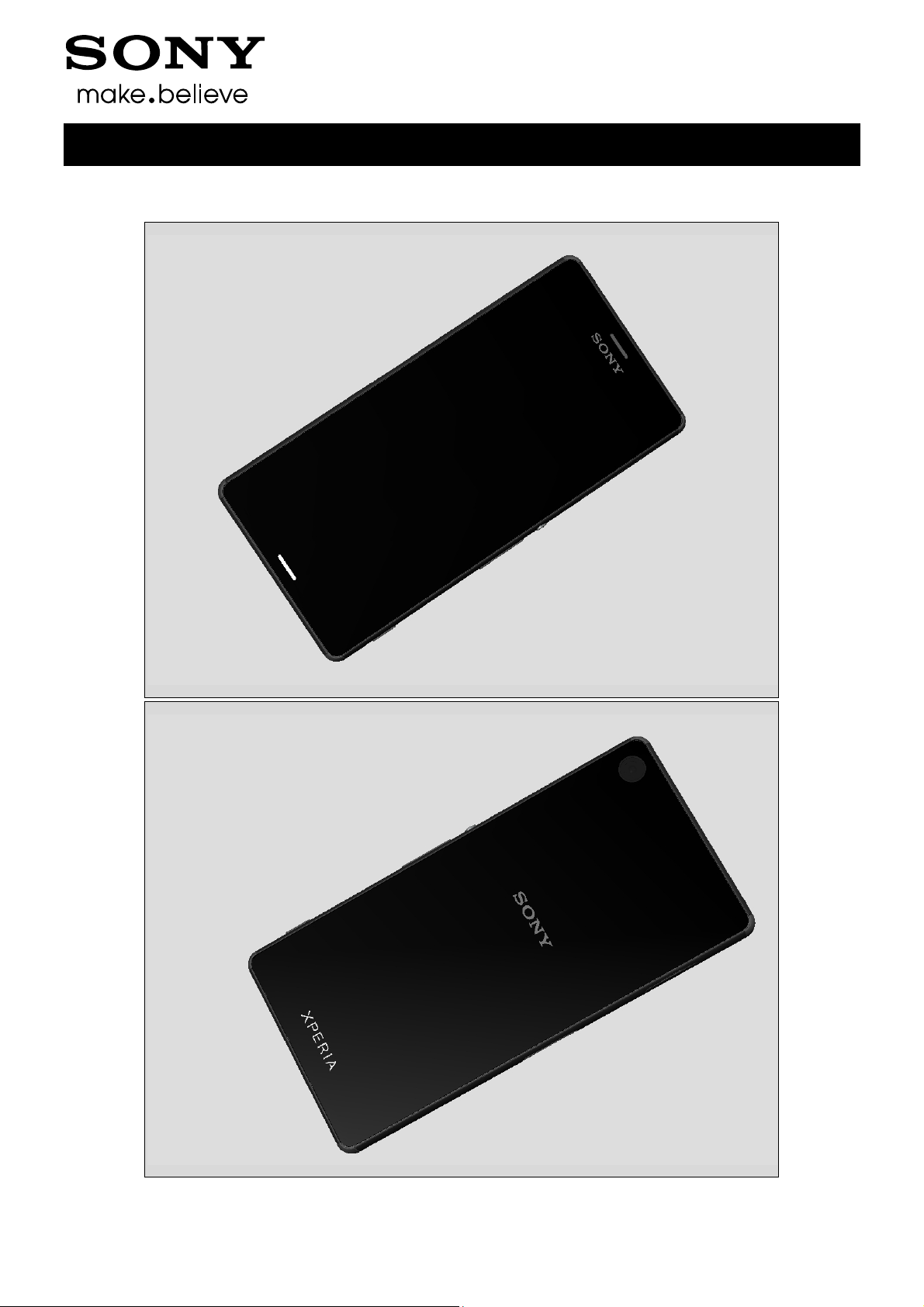
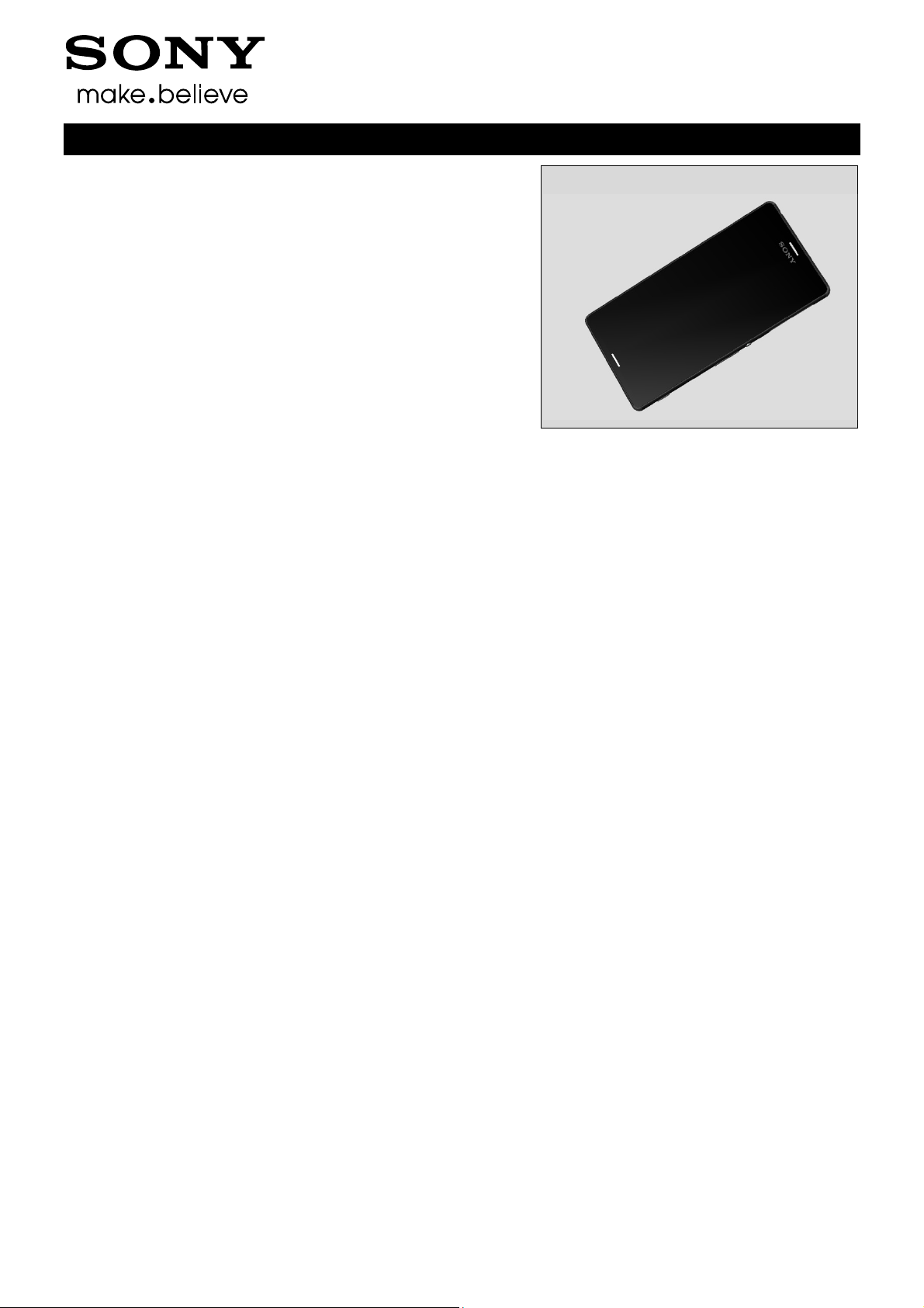
1 Exterior Views
1.1 D6603, D6616, D6643, D6653
Working Instructions (mech)
1288-9438 Rev 2
© Sony Mobile Communications AB – Company Internal 6(97)
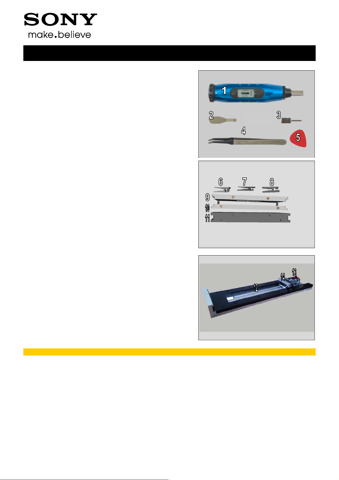
2 Tools
SPECIAL TOOLS
1. Torque Screwdriver
2. Front Opening Tool
3. Bits (JCIS No 0)
4. Flex Film Assembly Tool
5. Guitar Pick
6. Audio Jack Press
7. Press Tool Loudspeaker
8. Speaker FPC Press
9. Rear Panel Press Top Inlay
10. Bottom Press Inlay
11. Rear Panel Adhesive alignment fixture
Working Instructions (mech)
12. Side Panel press
13. Side Panel Press Head
14. Charge connector press pad
For part no’s on the tools above, refer to the ‘Tools Catalogue/Matrix’.
1288-9438 Rev 2
© Sony Mobile Communications AB – Company Internal 7(97)
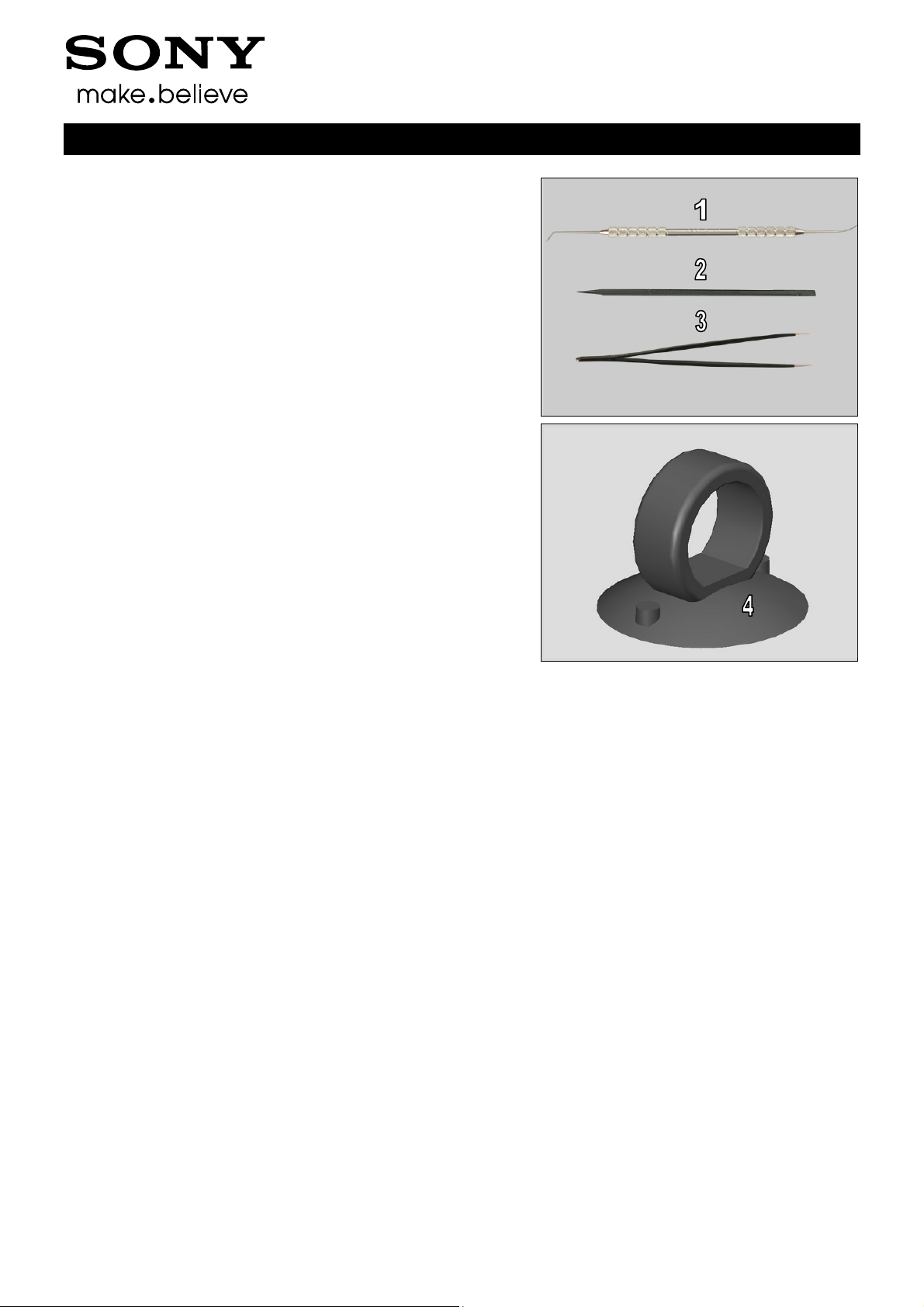
Tools
STANDARD TOOLS
1. Dentist Hook
2. Nylon Pointer
3. Tweezers
4. Suction Cup
Working Instructions (mech)
1288-9438 Rev 2
© Sony Mobile Communications AB – Company Internal 8(97)
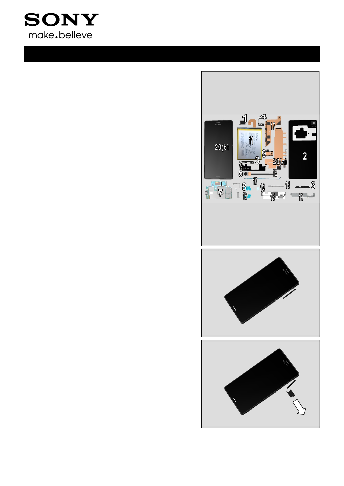
3 Disassembly
The disassembly is done in the following order:
1. Sim Tray
2. Rear Panel
3. Sub Antenna
4. Holder Main Camera
5. Main Camera
6. Antenna BT + WLAN
7. Main PBA
8. Shield Main Camera
9. Audio Jack
10. RF cable
11. Embedded Battery
12. Cushion Battery
13. Main Antenna
14. Holder Vibrator
15.Plate Speaker
16. Holder Speaker sub assembly
17. Charge FPC
18. Holder key volume
19. Plate Holder Speaker
20. Relay FPC (a) + Front Assy (b)
Working Instructions (mech)
3.1 Sim Tray
Open the Cap SD
Remove the Sim Tray with fingers
1288-9438 Rev 2
© Sony Mobile Communications AB – Company Internal 9(97)
Disassembly
Close the Cap SD
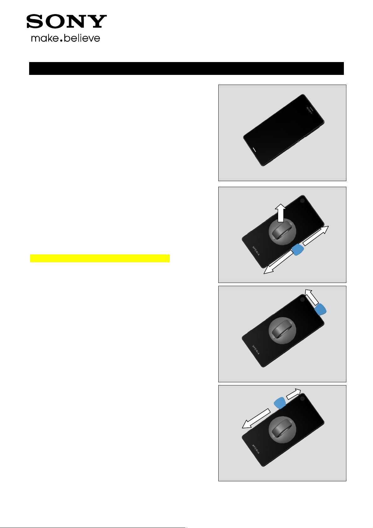
3.2 Rear Panel
Use Suction cup to get space for inserting the Guitar Pick.
Gently slide the Guitar Pick along to release all sides of the
Rear Panel.
Note! Start in the middle of the right long side!
Working Instructions (mech)
1288-9438 Rev 2
© Sony Mobile Communications AB – Company Internal 10(97)
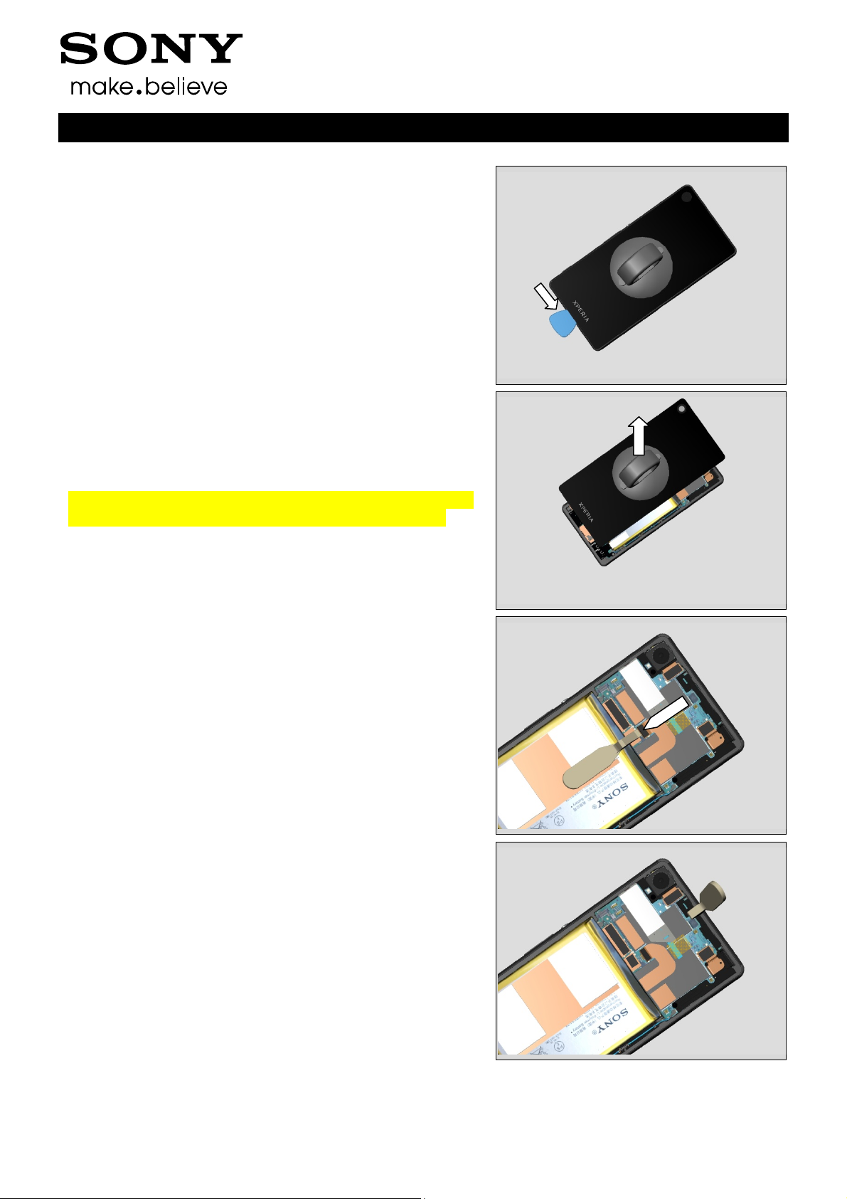
Disassembly
Remove the Rear Panel by using the Suction cup.
Note! Be careful when removing the Rear Panel due to the
adhesive between Embedded Battery and Rear Panel.
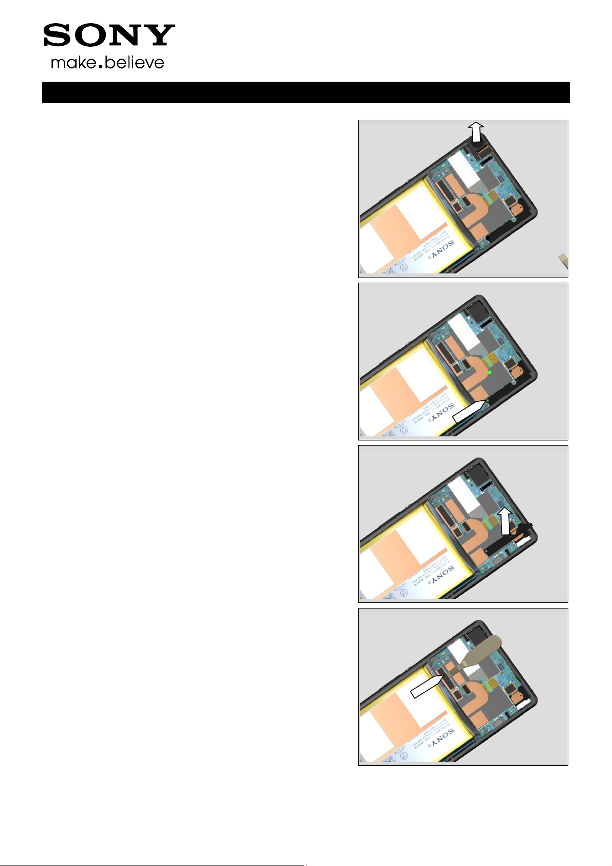
Working Instructions (mech)
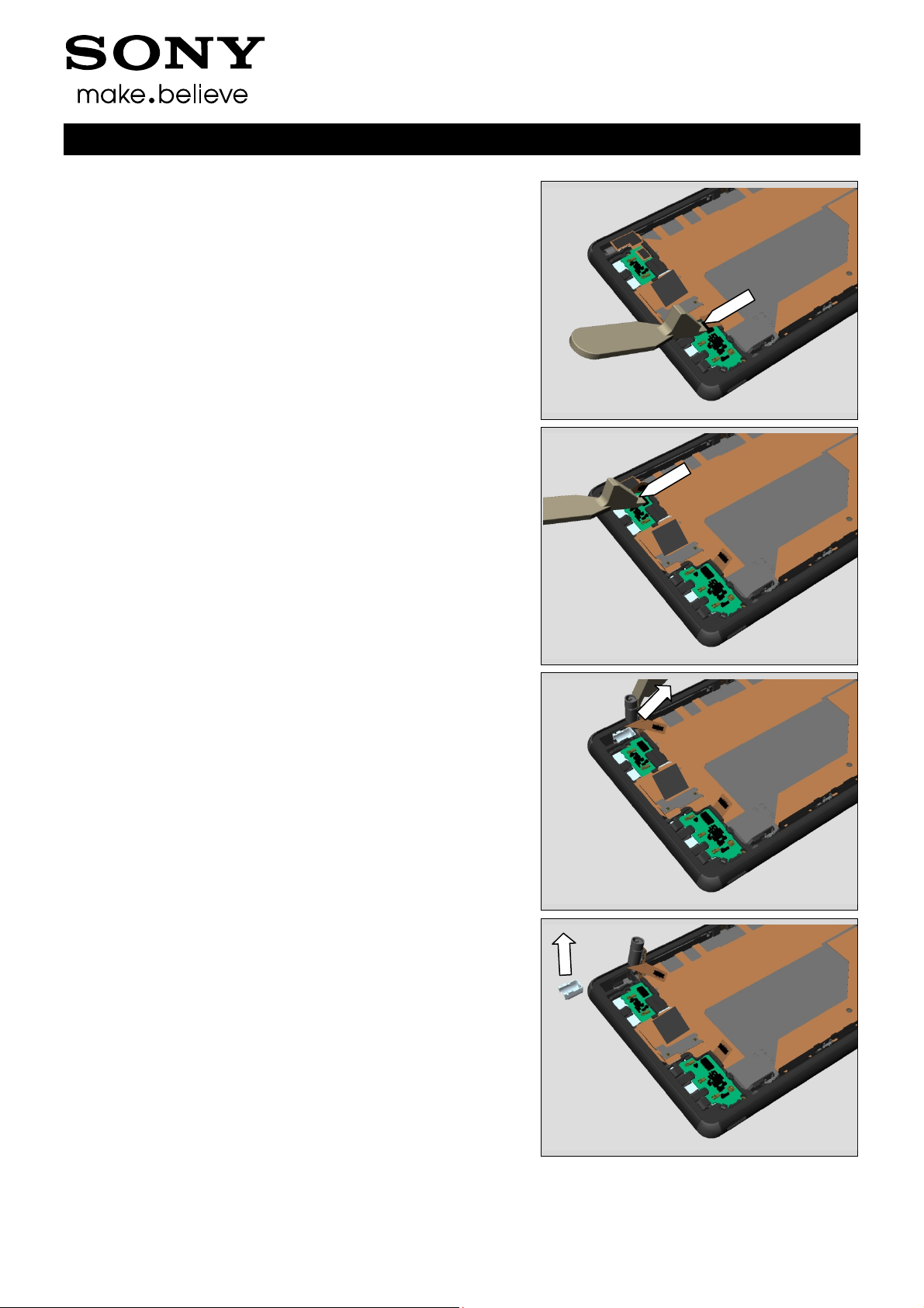
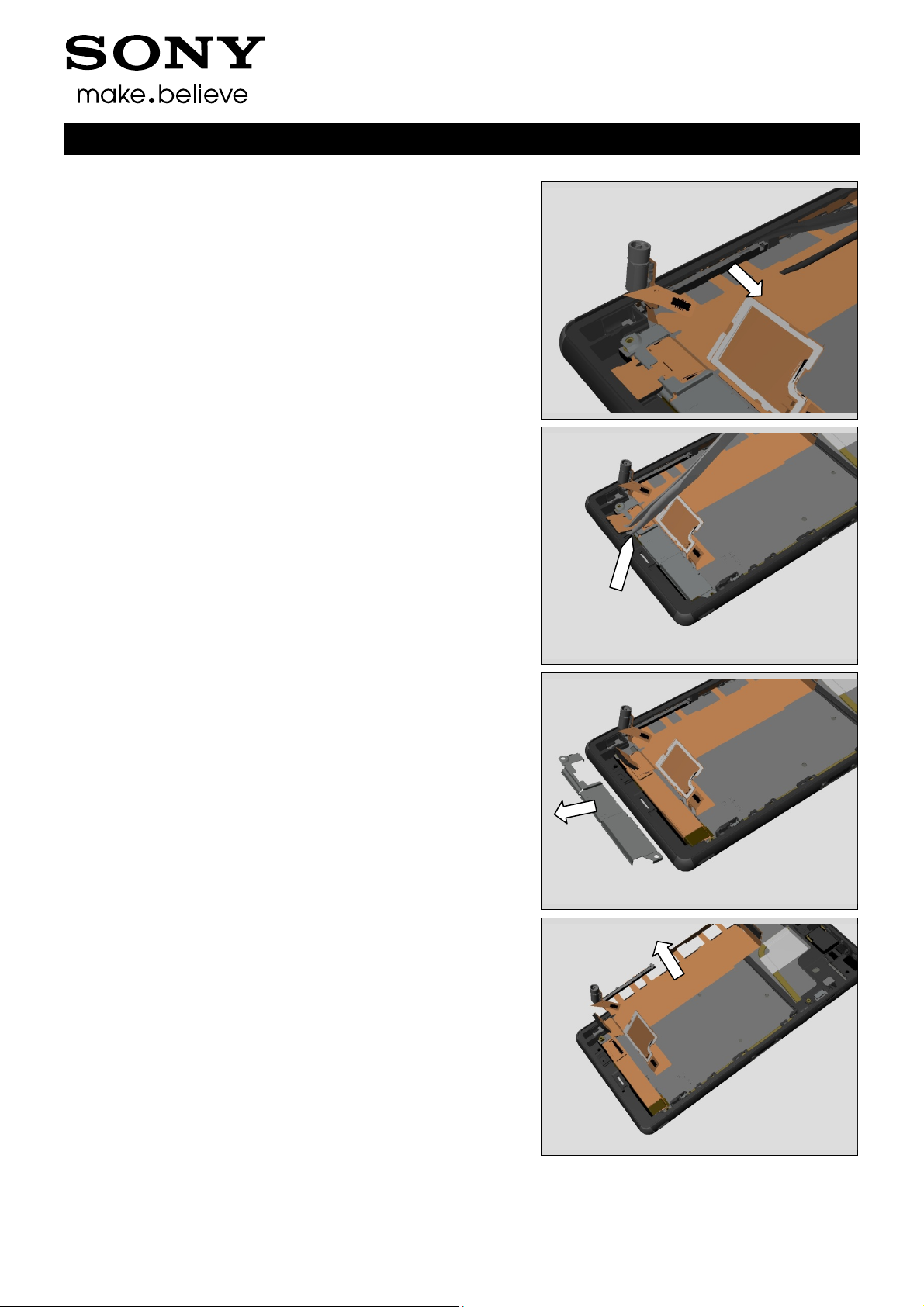
Use a Front Opening Tool to disconnect the BtB connector.
3.3 Sub Antenna
Remove the Sub Antenna by using a Front Opening Tool.
1288-9438 Rev 2
© Sony Mobile Communications AB – Company Internal 11(97)
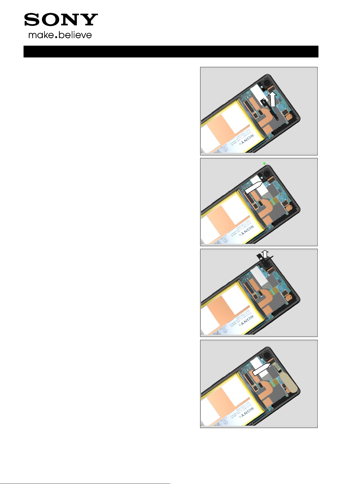
Disassembly
Remove the Sub Antenna.
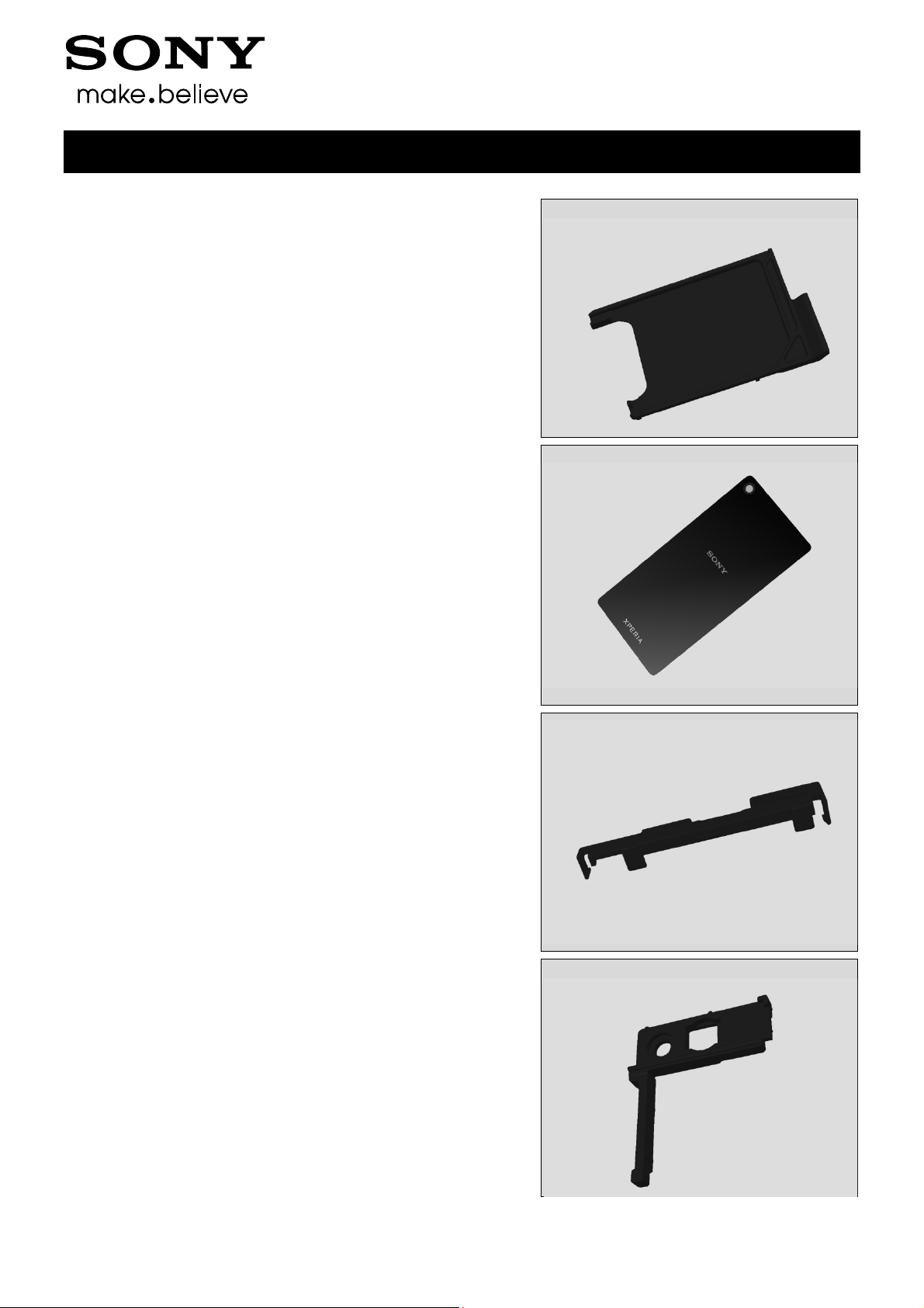
3.4 Holder Main Camera
Remove the Screw Other Len:2.6 Diam:1.4 by using a
screwdriver with Bits (JCIS No 0).
Working Instructions (mech)
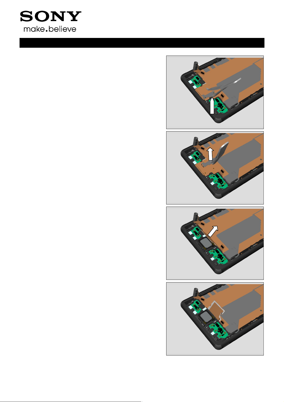
Remove Holder Main Camera
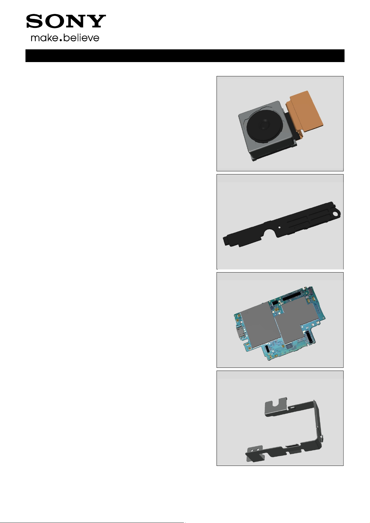
3.5 Main Camera
Use a Front Opening Tool to disconnect the BtB connector.
1288-9438 Rev 2
© Sony Mobile Communications AB – Company Internal 12(97)
Disassembly
Remove the Camera. Be careful not to damage it.
3.6 Antenna BT + WLAN
Remove the Screw Other Len:2.6 Diam:1.4 by using a
screwdriver with Bits (JCIS No 0).
Working Instructions (mech)
Remove the Antenna BT + WLAN with fingers.
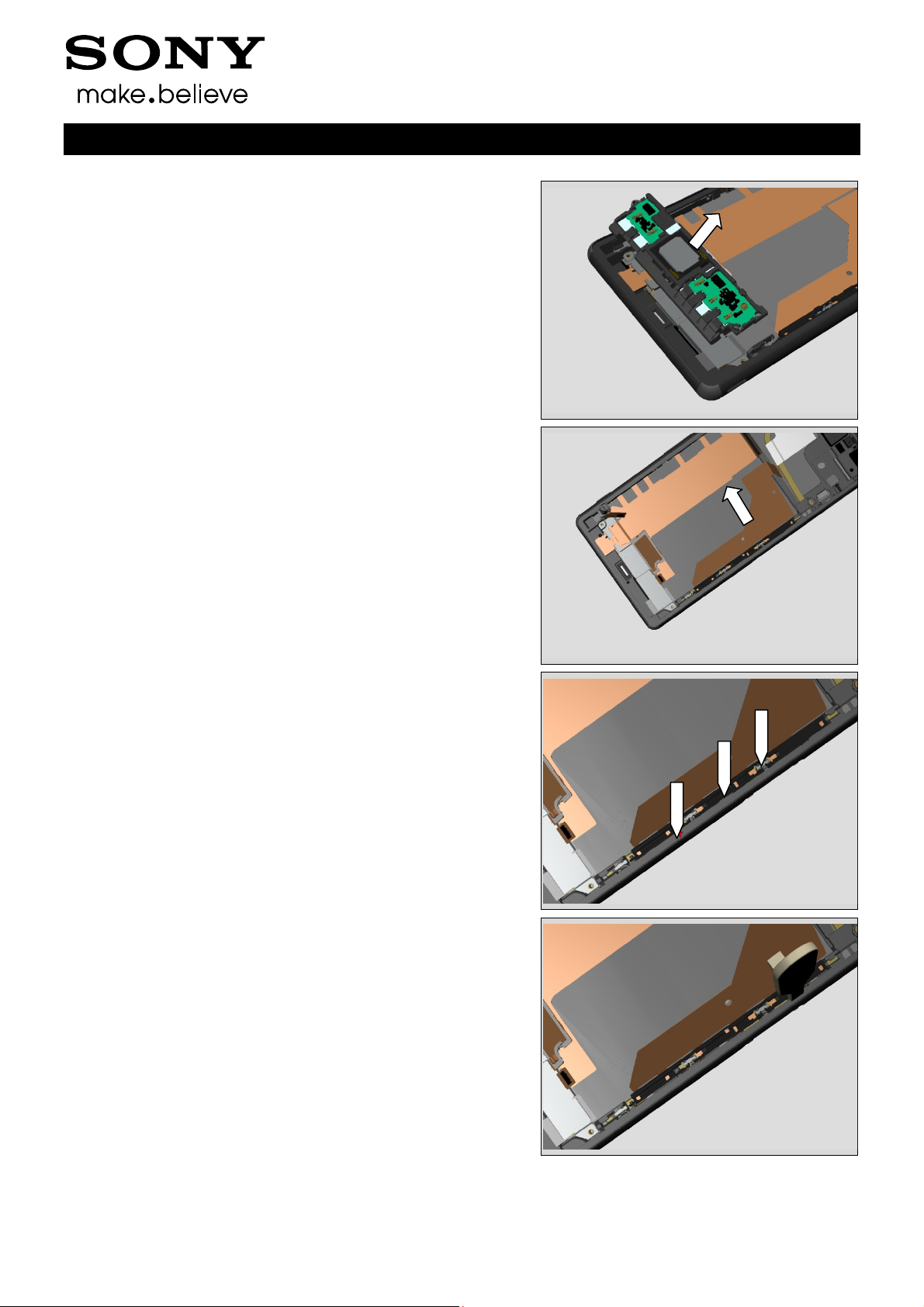
3.7 Main PBA
Use a Front Opening Tool to disconnect the BtB connector
for Relay FPC.
1288-9438 Rev 2
© Sony Mobile Communications AB – Company Internal 13(97)
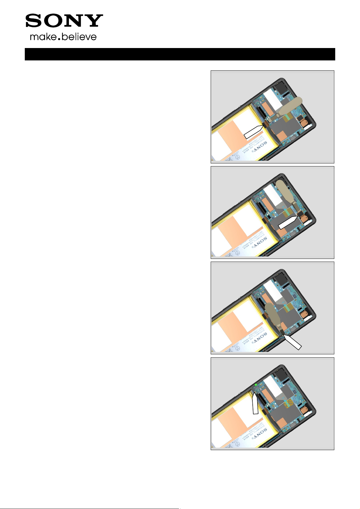
Disassembly
Use a Front Opening Tool to disconnect the BtB connector
for Charger FPC.
Use a Front Opening Tool to disconnect the BtB connector
for Audio Jack.
Working Instructions (mech)
Use a Front Opening Tool to disconnect the RF cable
connector.
Remove the Screw Other Len:2.6 Diam:1.4 by using a
screwdriver with Bits (JCIS No 0).
1288-9438 Rev 2
© Sony Mobile Communications AB – Company Internal 14(97)
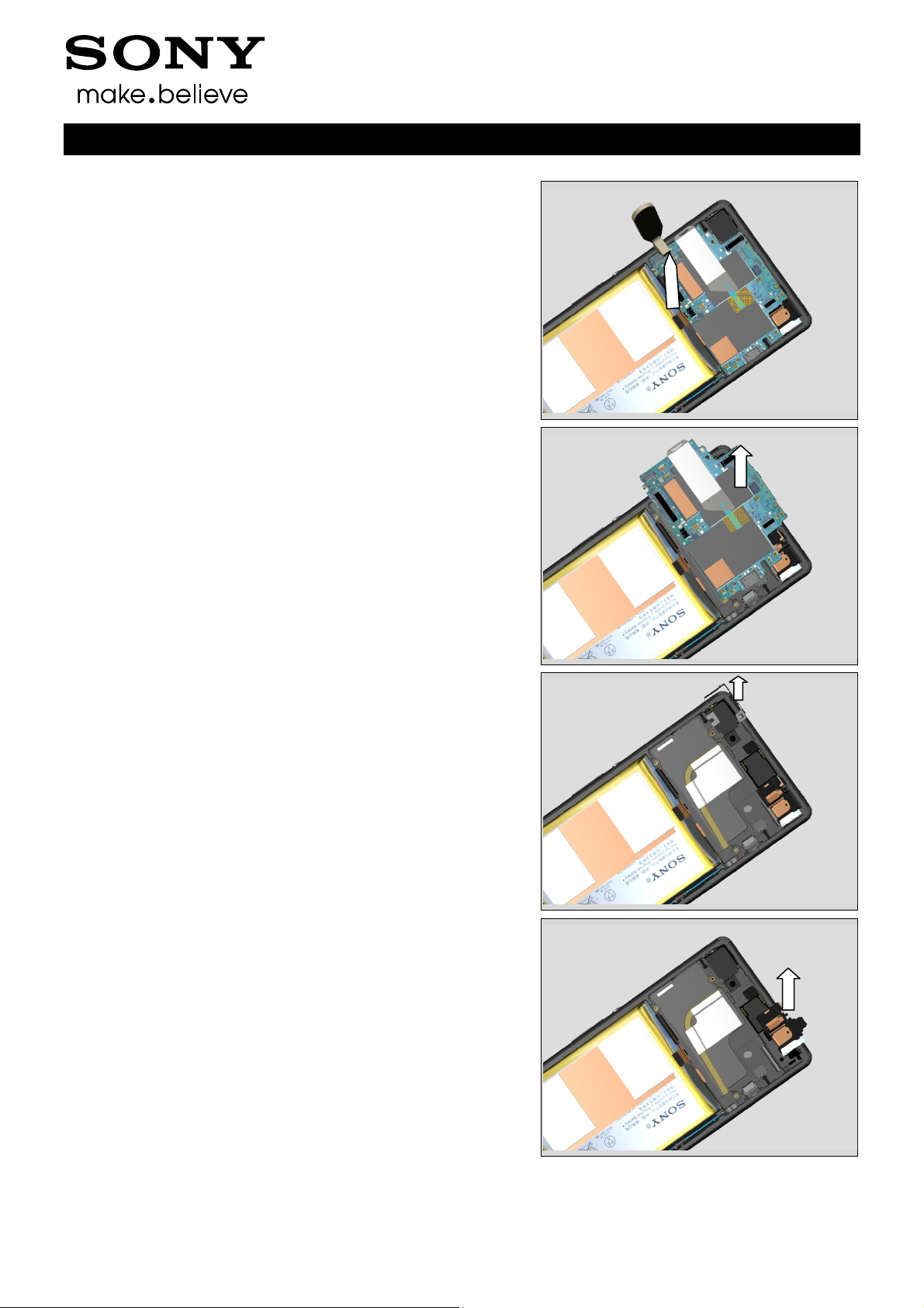
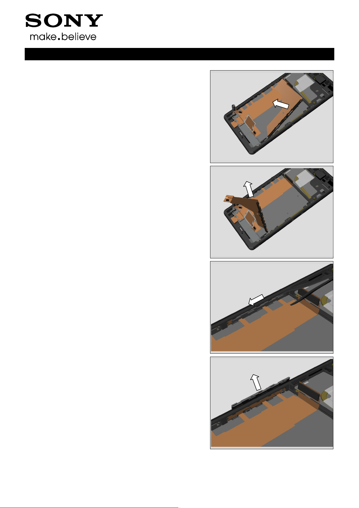
Disassembly
Insert the Front Opening Tool to release the Main PBA.
Remove the Main PBA
Working Instructions (mech)
3.8 Shield Main Camera
Remove Shield Main Camera with a pair of tweezers.
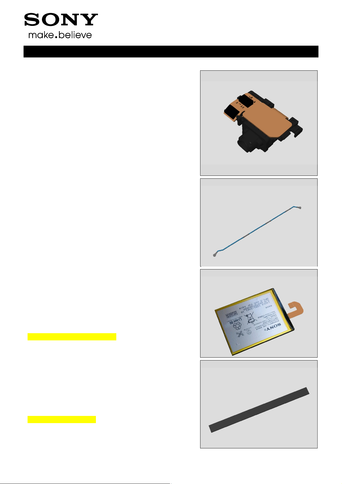
3.9 Audio Jack
Remove the Audio Jack with fingers.
1288-9438 Rev 2
© Sony Mobile Communications AB – Company Internal 15(97)

Disassembly
3.10 RF cable
Use a Front Opening Tool to disconnect the RF cable
connector.
Remove the RF cable with fingers
Working Instructions (mech)
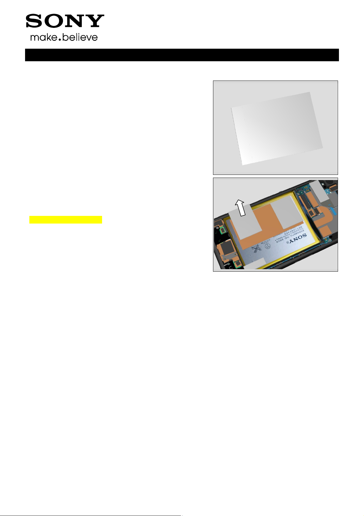
3.11 Embedded Battery
Remove the Embedded Battery by pull the tab (red arrow)
with fingers
3.12 Cushion Battery
Remove the Cushion Battery using a Front Opening Tool
and fingers.
1288-9438 Rev 2
© Sony Mobile Communications AB – Company Internal 16(97)
Disassembly
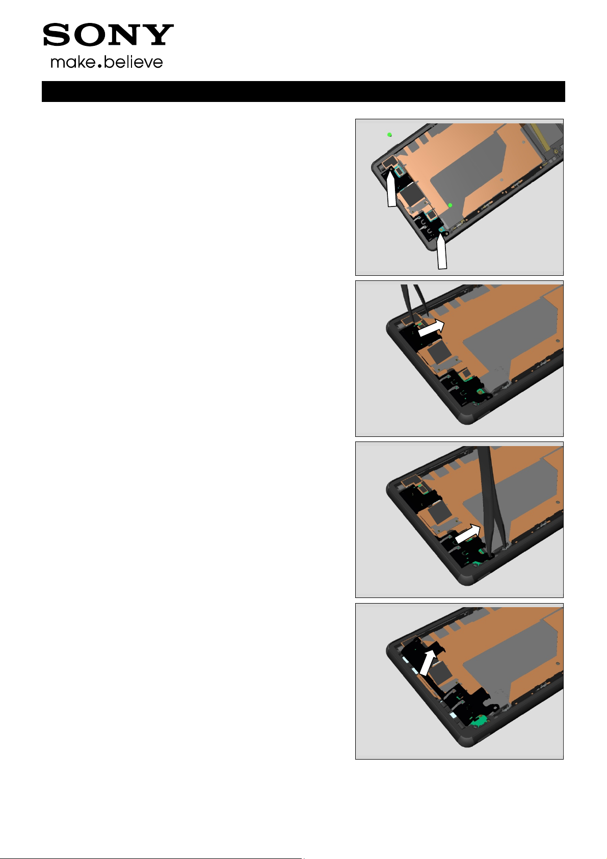
3.13 Main Antenna
Remove the two Screw Other Len:4.0 Diam:1.4 by using a
screwdriver with Bits (JCIS No 0).
Insert the Flex Film Assembly Tool to release left side of
Main Antenna
Working Instructions (mech)
Insert the Flex Film Assembly Tool to release right side of
Main Antenna
Remove Main Antenna with fingers
1288-9438 Rev 2
© Sony Mobile Communications AB – Company Internal 17(97)
Disassembly
3.14 Holder Vibrator
Use a Front Opening Tool to disconnect the BtB connector.
Use a Front Opening Tool to disconnect the BtB connector.
Working Instructions (mech)
Lift the Vibrator
Remove the Holder Vibrator with a pair of tweezers.
1288-9438 Rev 2
© Sony Mobile Communications AB – Company Internal 18(97)
Disassembly
3.15 Plate Speaker
Detach the Plate Speaker with Flex Film Assembly Tool.
Remove the Plate Speaker with Flex Film Assembly Tool.
Working Instructions (mech)
3.16 Holder Speaker sub
assembly
Lift up the Relay FPC over Holder Speaker sub assembly
with a Flex Film Assembly Tool
Unsnap the Holder Speaker sub assembly with fingers
1288-9438 Rev 2
© Sony Mobile Communications AB – Company Internal 19(97)
Disassembly
Remove it.
3.17 Charge FPC
Detach the adhesive under the Charge FPC
Working Instructions (mech)
Charge FPC has three hooks
Detach the Charge FPC from Front Assy using Front
Opening Tool
1288-9438 Rev 2
© Sony Mobile Communications AB – Company Internal 20(97)
Disassembly
Lift up the Charge FPC
Remove the Charge FPC
Working Instructions (mech)
3.18 Holder key volume
Detach the Holder key volume to the left using a Flex Film
Assembly Tool
Remove the Holder key volume
1288-9438 Rev 2
© Sony Mobile Communications AB – Company Internal 21(97)
Disassembly
Unsnap the Holder camera key of Relay FPC
3.19 Plate holder speaker
Detach the Holder Mic sub assembly of Relay FPC from
Front Assy with a Flex Film Assembly Tool.
Working Instructions (mech)
Remove the Plate holder speaker using a pair of tweezers.
3.20 Relay FPC + Front Assy
Detach the adhesive under Relay FPC and remove it
1288-9438 Rev 2
© Sony Mobile Communications AB – Company Internal 22(97)
4 Replacement
4.1 Sim Tray
Follow the 3.1 Disassembly instructions!
Prepare the new Sim Tray.
Follow the 5.20 Reassembly instructions!
4.2 Rear Panel
Follow the 3.2 Disassembly instructions!
Prepare the new Rear Panel.
Follow the 4.26 Installation instructions!
Follow the 5.19 Reassembly instructions!
Working Instructions (mech)
4.3 Sub Antenna
Follow the 3.2 – 3.3 Disassembly instructions!
Prepare the new Sub Antenna.
Follow the 4.61, 4.65 Installation instructions!
Follow the 5.18-5.19 Reassembly instructions!
4.4 Holder Main Camera
Follow the 3.2 and 3.6 Disassembly instructions!
Prepare the new Holder Main Camera.
Follow the 5.17 and 5.19 Reassembly instructions!
1288-9438 Rev 2
© Sony Mobile Communications AB – Company Internal 23(97)
Replacement
4.5 Main Camera
Follow the 3.2 and 3.4-3.5 Disassembly instructions!
Prepare the new Main Camera.
Follow the 5.16-17 and 5.19 Reassembly instructions!
4.6 Antenna BT + WLAN
Follow the 3.2 and 3.6 Disassembly instructions!
Prepare the new Antenna BT + WLAN.
Follow the 4.52 Installation instructions!
Follow the 5.15 and 5.19 Reassembly instructions!
Working Instructions (mech)
4.7 Main PBA
Follow the 3.1 – 3.7 Disassembly instructions!
Follow the 4.66 Removal instructions!
Prepare the new Main PBA.
Follow the 4.66 Installation instructions!
Follow the 5.14 – 5.20 Reassembly instructions!
4.8 Shield Main Camera
Follow the 3.1 – 3.8 Disassembly instructions!
Prepare the new Shield Main Camera.
Follow the 4.44 Installation instructions!
Follow the 5.13 – 5.20 Reassembly instructions!
1288-9438 Rev 2
© Sony Mobile Communications AB – Company Internal 24(97)
Replacement
4.9 Audio Jack
Follow the 3.1 – 3.7 and 3.9 Disassembly instructions!
Prepare the new Audio Jack.
Follow 5.12 and 5.14 – 5.20 Reassembly instructions!
Working Instructions (mech)
4.10 RF cable
Follow the 3.2 and 3.10 Disassembly instructions!
Prepare the new RF cable.
Follow the 5.11 and 5.19 Reassembly instructions!
4.11 Embedded Battery
Follow the 3.2 and 3.11 Disassembly instructions!
Prepare the new Embedded Battery.
Follow the 4.36 Installation instructions!
Follow the 5.10 and 5.19 Reassembly instructions!
Visual Inspection of the Battery.
4.12 Cushion Battery
Follow the 3.2 and 3.11-3.12 Disassembly instructions!
Prepare the new Cushion Battery.
Follow the 5.9-5.10 and 5.19 Reassembly instructions!
Scrap! Not to be reused!
1288-9438 Rev 2
© Sony Mobile Communications AB – Company Internal 25(97)
Replacement
4.13 Main Antenna
Follow the 3.2 and 3.11-3.13 Disassembly instructions!
Prepare the new Main Antenna.
Follow the 5.8-5.10 and 5.19 Reassembly instructions!
Working Instructions (mech)
4.14 Holder Vibrator
Follow the 3.2 and 3.11-3.13 Disassembly instructions!
Prepare the new Holder Vibrator.
Follow the 5.7-5.10 and 5.19 Reassembly instructions!
4.15 Plate Speaker
Follow the 3.2 and 3.11-3.14 Disassembly instructions!
Prepare the new Plate Speaker.
Follow the 5.8-5.10 and 5.19 Reassembly instructions!
4.16 Holder Speaker sub
assembly
Follow the 3.2 and 3.11-3.14 Disassembly instructions!
Follow the 4.30, 4.67, 4.66, 4.54 Removal instructions!
Prepare the new Holder Speaker sub assembly
Follow the 4.30, 4.54, 4.25 4.66, 4.67
Installation instructions!
Follow the 5.8-5.10 and 5.19 Reassembly instructions!
1288-9438 Rev 2
© Sony Mobile Communications AB – Company Internal 26(97)
Replacement
4.17 Charge FPC
Follow the 3.2, 3.10-312 and 3.17 Disassembly instructions!
Prepare the new Charge FPC.
Follow the 4.36 Installation instructions!
Follow the 5.4, 5.9-5.11 and 5.19 Reassembly instructions!
Visual Inspection of the Charge FPC.
4.18 Holder key volume
Follow the 3.11-312 and 3.17 Disassembly instructions!
Prepare the new Holder key volume.
Follow the 5.9-5.10 and 5.19 Reassembly instructions!
Working Instructions (mech)
4.19 Plate holder speaker
Follow the 3.2, 3.11-3.16 and 3.19 Disassembly instructions!
Prepare the new Plate holder speaker.
Follow the 5.2, 5.5-5.10 and 5.8 Reassembly instructions!
4.20 Relay FPC
Follow the 3.2, 3.11-3.16 and 3.19 -3.20 Disassembly
instructions!
Follow the 4.27, 4. 28 Removal instructions!
Prepare the new Relay FPC.
Follow the 4.27, 4. 28, 4.36, 4.40, 4.42, 4.43, 4.47
Installation instructions!
Follow the 5.1-5.2, 5.5-5.10 and 5.8 Reassembly
instructions!
Visual Inspection of the Relay FPC.
1288-9438 Rev 2
© Sony Mobile Communications AB – Company Internal 27(97)
Replacement
4.21 Front Assy
Follow the 3.1 – 3.20 Disassembly instructions!
Follow the 4.48, 4.53 Removal instructions!
Prepare the new Front Assy.
Follow the 4.63, 4.64 Installation instructions!
Follow the 5.1 – 5.20 Reassembly instructions!
Working Instructions (mech)
1288-9438 Rev 2
© Sony Mobile Communications AB – Company Internal 28(97)
Replacement
4.22 Adhesive Battery Front
Follow the 3.2 and 3.11 Disassembly instructions!
Carry out the Removal as described below.
Prepare the new Adhesive Battery Front.
Carry out the Installation as described below.
Follow the 5.10 and 5.19 Reassembly instructions!
REMOVAL
Remove the Adhesive Battery Front with fingers.
Scrap! Not to be reused!
Working Instructions (mech)
INSTALLATION
Attach the Adhesive Battery Front with fingers.
1288-9438 Rev 2
© Sony Mobile Communications AB – Company Internal 29(97)
Replacement:
4.23 Adhesive Battery Rear
Follow the 3.2 Disassembly instructions!
Carry out the Removal as described below.
Prepare the new Adhesive Battery Rear.
Carry out the Installation as described below.
Follow the 5.19 Reassembly instructions!
REMOVAL
Detach to remove the Adhesive Battery Rear with the Flex
Film Assembly Tool
Scrap! Not to be reused!
INSTALLATION
Place a new Adhesive Battery Rear on the Embedded
Battery using a Flex Film Assembly Tool.
Working Instructions (mech)
1288-9438 Rev 2
© Sony Mobile Communications AB – Company Internal 30(97)

Replacement
4.24 Adhesive Battery Rear 2
Follow the 3.2 Disassembly instructions!
Carry out the Removal as described below.
Prepare the new Adhesive Battery Rear 2.
Carry out the Installation as described below.
Follow the 5.2 Reassembly instructions!
REMOVAL
Detach to remove the Adhesive Battery Rear 2 with the Flex
Film Assembly Tool
Scrap! Not to be reused!
INSTALLATION
Place a new Adhesive Battery Rear2 on the Embedded
Battery using a Flex Film Assembly Tool.
Working Instructions (mech)
1288-9438 Rev 2
© Sony Mobile Communications AB – Company Internal 31(97)

Replacement
4.25 Adhesive Charger FPC
Follow the 3.2, 3.10-3.12 and 3.17 Disassembly instructions!
Carry out the Removal as described below.
Prepare the new Adhesive Charger FPC.
Carry out the Installation as described below.
Follow the 5.4, 5.9-5.11 and 5.19 Reassembly instructions!
REMOVAL
Detach to remove the Adhesive Charger FPC with the
Dentist Hook.
Scrap! Not to be reused!
INSTALLATION
Place a new Adhesive Charger FPC on the Front Assy using
fingers
Working Instructions (mech)
1288-9438 Rev 2
© Sony Mobile Communications AB – Company Internal 32(97)

Replacement
4.26 Adhesive FPC Speaker
Follow the 3.2, 3.11 and 3.15 Disassembly instructions!
Carry out the Removal as described below.
Prepare the new Adhesive FPC Speaker.
Carry out the Installation as described below.
Follow the 5.6, 5.10 and 5.19 Reassembly instructions!
REMOVAL
Detach to remove the Adhesive FPC Speaker with the
Dentist Hook.
Scrap! Not to be reused!
Working Instructions (mech)
INSTALLATION
Place a new Adhesive FPC Speaker on the Holder Speaker
sub assembly using a pair of tweezers.
Fold down the Relay FPC on the Holder Speaker sub
assembly and press with Speaker FPC Press under five
seconds
1288-9438 Rev 2
© Sony Mobile Communications AB – Company Internal 33(97)

Replacement
4.27 Adhesive Rear Panel
Follow the 3.2 Disassembly instructions!
Carry out the Removal as described below.
Prepare the new Adhesive Rear Panel.
Carry out the Installation as described below.
Follow the 5.19 Reassembly instructions!
REMOVAL
Remove the old Adhesive Rear Panel and all remains of
the Adhesive residue.
Clean the edges of the Rear Panel carefully with alcohol
before the new Adhesive Rear Panel is mounted. This action
is done to secure the water resistant of the unit.
Scrap! Not to be reused!
Working Instructions (mech)
INSTALLATION
Place the new Adhesive Rear Panel in the Rear Panel
adhesive alignment fixture and the Rear Panel in a correct
position.
Press to secure the attachment.
1288-9438 Rev 2
© Sony Mobile Communications AB – Company Internal 34(97)

Replacement
4.28 Adhesive Relay FPC A
Follow the 3.2, 3.11-3.16 and 3.18-3.20 Disassembly
instructions!
Carry out the Removal as described below.
Prepare the new Adhesive Relay FPC A.
Carry out the Installation as described below.
Follow the 5.1-5.3, 5.5-5.10 and 5.19 Reassembly
instructions!
REMOVAL
Detach to remove the Adhesive Relay FPC A with the
Dentist Hook.
Scrap! Not to be reused!
INSTALLATION
Place a new Adhesive Relay FPC A on the Front Assy using
fingers
Working Instructions (mech)
1288-9438 Rev 2
© Sony Mobile Communications AB – Company Internal 35(97)

Replacement
4.29 Adhesive Relay FPC B
Follow the 3.2, 3.11-3.16 and 3.18-3.20 Disassembly
instructions!
Carry out the Removal as described below.
Prepare the new Adhesive Relay FPC B.
Carry out the Installation as described below.
Follow the 5.1-5.3, 5.5-5.10 and 5.19 Reassembly
instructions!
REMOVAL
Detach to remove the Adhesive Relay FPC B with the
Dentist Hook.
Scrap! Not to be reused!
INSTALLATION
Place a new Adhesive Relay FPC B on the Front Assy using
fingers
Working Instructions (mech)
1288-9438 Rev 2
© Sony Mobile Communications AB – Company Internal 36(97)

Replacement
4.30 Adhesive WP Audio Jack
Follow the 3.1 – 3.7 Disassembly instructions!
Carry out the Removal as described below.
Prepare the new Adhesive WP Audio Jack.
Carry out the Installation as described below.
Follow the 5.14 – 5.20 Reassembly instructions!
REMOVAL
Detach to remove the Adhesive WP Audio Jack with the
Flex Film Assembly Tool.
Scrap! Not to be reused!
INSTALLATION
Place a new Adhesive WP Audio Jack the Audio Jack using
a Flex Film Assembly Tool.
Working Instructions (mech)
1288-9438 Rev 2
© Sony Mobile Communications AB – Company Internal 37(97)

Replacement
4.31 Adhesive WP holder
speaker
Follow the 3.2 and 3.11-3.16 Disassembly instructions!
Carry out the Removal as described below.
Prepare the new Adhesive WP holder speaker.
Carry out the Installation as described below.
Follow the 5.5-5.10 and 5.19 Reassembly instructions!
REMOVAL
Detach to remove the Adhesive WP holder speaker with the
Dentist Hook.
Scrap! Not to be reused!
INSTALLATION
Place a new Adhesive WP holder speaker on the Front Assy
using a Flex Film Assembly Tool.
Working Instructions (mech)
1288-9438 Rev 2
© Sony Mobile Communications AB – Company Internal 38(97)

Replacement
Working Instructions (mech)
4.32 Adhesive WP Speaker
Follow the 3.2, 3.11 and 3.15 Disassembly instructions!
Follow the 4.25, 4.54 Removal instructions!
Carry out the Removal as described below.
Prepare the new Adhesive WP Speaker.
Carry out the Installation as described below.
Follow the 4.54, 4.25 Installation instructions!
Follow the 5.6, 5.10 and 5.19 Reassembly instructions!
REMOVAL
Detach to remove the Adhesive WP Speaker with the
Dentist Hook.
Scrap! Not to be reused!
INSTALLATION
Place a new Adhesive WP Speaker on the Holder Speaker
sub assembly using a Flex Film Assembly Tool.
1288-9438 Rev 2
© Sony Mobile Communications AB – Company Internal 39(97)

Replacement:
4.33 Cap SD
Carry out the Removal as described below.
Prepare the new Cap SD.
Carry out the Installation as described below.
REMOVAL
Detach to remove the Cap SD with fingers
INSTALLATION
Place a new Cap SD with fingers and a pair of tweezers
Working Instructions (mech)
1288-9438 Rev 2
© Sony Mobile Communications AB – Company Internal 40(97)

Replacement
4.34 Cap USB
Carry out the Removal as described below.
Prepare the new Cap USB.
Carry out the Installation as described below.
REMOVAL
Detach to remove the Cap USB with fingers
INSTALLATION
Place a new Cap USB with fingers and a pair of tweezers
Working Instructions (mech)
1288-9438 Rev 2
© Sony Mobile Communications AB – Company Internal 41(97)

Replacement:
4.35 Core Unit Label
Carry out the Removal as described below.
Prepare the new Core Unit Label.
Carry out the Installation as described below.
REMOVAL
Open Cap SD and pull out the Label Plate. Then remove the
Core Unit Label with a Dentist Hook.
Scrap! Not to be reused!
INSTALLATION
Attach new Core Unit Label with fingers and close Cap SD.
Working Instructions (mech)
1288-9438 Rev 2
© Sony Mobile Communications AB – Company Internal 42(97)

Replacement:
4.36 Cushion Audio Jack FPC
BtB
Follow the 3.2 Disassembly instructions!
Carry out the Removal as described below.
Prepare the new Cushion Audio Jack FPC BtB.
Carry out the Installation as described below.
Follow the 5.19 Reassembly instructions!
REMOVAL
Detach to remove the Cushion Audio Jack FPC BtB with the
Flex Film Assembly Tool.
Scrap! Not to be reused!
INSTALLATION
Place a new Cushion Audio Jack FPC BtB on the Audio
Jack FPC using a Flex Film Assembly Tool.
Working Instructions (mech)
1288-9438 Rev 2
© Sony Mobile Communications AB – Company Internal 43(97)

Replacement:
4.37 Cushion Battery FPC BtB
Follow the 3.2 Disassembly instructions!
Carry out the Removal as described below.
Prepare the new Cushion Battery FPC BtB.
Carry out the Installation as described below.
Follow the 5.19 Reassembly instructions!
REMOVAL
Detach to remove the Cushion Battery FPC BtB with the
Flex Film Assembly Tool.
Scrap! Not to be reused!
INSTALLATION
Place a new Cushion Battery FPC BtB on the Embedded
Battery FPC using a Flex Film Assembly Tool.
Working Instructions (mech)
REMOVAL
Detach to remove the Cushion Battery FPC BtB with the
Flex Film Assembly Tool.
Scrap! Not to be reused!
INSTALLATION
Place a new Cushion Battery FPC BtB on the Charge FPC
BtB using a Flex Film Assembly Tool.
1288-9438 Rev 2
© Sony Mobile Communications AB – Company Internal 44(97)

Replacement
4.38 Cushion Camera BtB
Follow the 3.2 Disassembly instructions!
Carry out the Removal as described below.
Prepare the new Cushion Camera BtB.
Carry out the Installation as described below.
Follow the 5.19 Reassembly instructions!
REMOVAL
Detach to remove the Cushion Camera BtB with the Flex
Film Assembly Tool.
Scrap! Not to be reused!
INSTALLATION
Place a new Cushion Camera BtB on the Main Camera FPC
using a Flex Film Assembly Tool.
Working Instructions (mech)
1288-9438 Rev 2
© Sony Mobile Communications AB – Company Internal 45(97)

Replacement:
4.39 Cushion Chat Camera
Follow the 3.1-3.8 Disassembly instructions!
Carry out the Removal as described below.
Prepare the new Cushion Chat Camera.
Carry out the Installation as described below.
Follow the 5.13-5.20Reassembly instructions!
REMOVAL
Detach to remove the Cushion Chat Camera with the Flex
Film Assembly Tool.
Scrap! Not to be reused!
INSTALLATION
Place a new Cushion Chat Camera on the Front Assy using
a Flex Film Assembly Tool.
Working Instructions (mech)
1288-9438 Rev 2
© Sony Mobile Communications AB – Company Internal 46(97)

Replacement
4.40 Cushion Rear Panel
Follow the 3.2 Disassembly instructions!
Carry out the Removal as described below.
Prepare the new Cushion Rear Panel.
Carry out the Installation as described below.
Follow the 5.19Reassembly instructions!
REMOVAL
Detach to remove the Cushion Rear Panel with a dentist
hook.
Scrap! Not to be reused!
INSTALLATION
Place a new Cushion Rear Panel on the Rear Panel using a
Flex Film Assembly Tool.
Working Instructions (mech)
1288-9438 Rev 2
© Sony Mobile Communications AB – Company Internal 47(97)

Replacement:
4.41 Cushion Relay FPC bottom
BtB
Follow the 3.2 Disassembly instructions!
Carry out the Removal as described below.
Prepare the new Cushion Relay FPC bottom BtB.
Carry out the Installation as described below.
Follow the 5.19 Reassembly instructions!
REMOVAL
Detach to remove the Cushion Relay FPC bottom BtB with
the Flex Film Assembly Tool.
Scrap! Not to be reused!
INSTALLATION
Place a new Cushion Relay FPC bottom BtB on the Relay
FPC using a Flex Film Assembly Tool.
Working Instructions (mech)
1288-9438 Rev 2
© Sony Mobile Communications AB – Company Internal 48(97)

Replacement:
4.42 Cushion Relay FPC BtB
Follow the 3.2 Disassembly instructions!
Carry out the Removal as described below.
Prepare the new Cushion Relay FPC BtB.
Carry out the Installation as described below.
Follow the 4.19 Reassembly instructions!
REMOVAL
Detach to remove the Cushion Relay FPC BtB with the Flex
Film Assembly Tool.
Scrap! Not to be reused!
INSTALLATION
Place a new Cushion Relay FPC BtB on the Relay FPC
using a Flex Film Assembly Tool.
Working Instructions (mech)
1288-9438 Rev 2
© Sony Mobile Communications AB – Company Internal 49(97)

Replacement:
4.43 Cushion Speaker
Follow the 3.2Disassembly instructions!
Carry out the Removal as described below.
Prepare the new Cushion Speaker.
Carry out the Installation as described below.
Follow the 5.19 Reassembly instructions!
REMOVAL
Detach to remove the Cushion Speaker with the Flex Film
Assembly Tool.
Scrap! Not to be reused!
INSTALLATION
Place a new Cushion Speaker on the Relay FPC using a
Flex Film Assembly Tool.
Working Instructions (mech)
1288-9438 Rev 2
© Sony Mobile Communications AB – Company Internal 50(97)

Replacement:
4.44 Cushion Vibrator
Follow the 3.2 Disassembly instructions!
Carry out the Removal as described below.
Prepare the new Cushion Vibrator.
Carry out the Installation as described below.
Follow the 5.19 Reassembly instructions!
REMOVAL
Detach to remove the Cushion Vibrator with the Flex Film
Assembly Tool.
Scrap! Not to be reused!
INSTALLATION
Place a new Cushion Vibrator on the Relay FPC using a
Flex Film Assembly Tool.
Working Instructions (mech)
1288-9438 Rev 2
© Sony Mobile Communications AB – Company Internal 51(97)

Replacement:
4.45 Gasket conductive USB
Follow the 3.1 – 3.8Disassembly instructions!
Carry out the Removal as described below.
Prepare the new Gasket conductive USB.
Carry out the Installation as described below.
Follow the 5.13 – 5.20 Reassembly instructions!
REMOVAL
Detach to remove the Gasket conductive USB with the
Dentist Hook.
Scrap! Not to be reused!
INSTALLATION
Place a new Gasket conductive USB on the Front Assy
using a pair of tweezers.
Working Instructions (mech)
REMOVAL
Detach to remove the Gasket conductive USB with the
Dentist Hook.
Scrap! Not to be reused!
INSTALLATION
Place a new Gasket conductive USB on the Shield Main
Camera using a pair of tweezers.
1288-9438 Rev 2
© Sony Mobile Communications AB – Company Internal 52(97)

Replacement
4.46 Gore Sheet(1st mic)
Follow the 3.2 and 3.11-3.16 Disassembly instructions!
Carry out the Removal as described below.
Prepare the new Gore Sheet(1
Carry out the Installation as described below.
Follow the 5.5-5.10 and 5.19 Reassembly instructions!
REMOVAL
Detach to remove the Gore Sheet(1
Hook.
Scrap! Not to be reused!
INSTALLATION
Place a new Gore Sheet(1
pair of tweezers.
st
mic).
st
mic) with the Dentist
st
mic) on the Front Assy using a
Working Instructions (mech)
1288-9438 Rev 2
© Sony Mobile Communications AB – Company Internal 53(97)

Replacement
4.47 Grill Receiver
Follow the 3.1 – 3.7 Disassembly instructions!
Follow the 4.53 Removal instructions!
Carry out the Removal as described below.
Prepare the new Grill Receiver.
Carry out the Installation as described below.
Follow the 4.53 Installation instructions!
Follow the 5.14 – 5.20 Reassembly instructions!
REMOVAL
Detach to remove the Grill Receiver with the Dentist Hook.
Scrap! Not to be reused!
INSTALLATION
Place a new Grill Receiver on the Front Assy using a Flex
Film Assembly Tool.
Working Instructions (mech)
1288-9438 Rev 2
© Sony Mobile Communications AB – Company Internal 54(97)

Replacement
4.48 Holder Mic sub assembly
Follow the 3.2 and 3.11-3.16 Disassembly instructions!
Carry out the Removal as described below.
Prepare the new Holder Mic sub assembly.
Carry out the Installation as described below.
Follow the 5.5-5.10 and 3.2 Reassembly instructions!
REMOVAL
Remove Holder Mic sub assembly with a Flex Film
Assembly Tool.
Working Instructions (mech)
INSTALLATION
Place a new Holder Mic sub assembly on the Relay FPC
using a Flex Film Assembly Tool.
1288-9438 Rev 2
© Sony Mobile Communications AB – Company Internal 55(97)

Replacement:
4.49 Holder Receiver sub
assembly
Follow the 3.1 – 3.7 Disassembly instructions!
Carry out the Removal as described below.
Prepare the new Holder Receiver sub assembly.
Carry out the Installation as described below.
Follow the 5.14 – 5.20 Reassembly instructions!
REMOVAL
Remove Holder Receiver sub assembly with a pair of
tweezers.
Working Instructions (mech)
INSTALLATION
Place a new Holder Receiver sub assembly on the Front
Assy using a pair of tweezers.
1288-9438 Rev 2
© Sony Mobile Communications AB – Company Internal 56(97)

Replacement:
4.50 Label Plate
Follow the 3.2 Disassembly instructions!
Carry out the Removal as described below.
Prepare the new Label Plate.
Carry out the Installation as described below.
Follow the 5.19 Reassembly instructions!
REMOVAL
Remove Label Plate with a Flex Film AssemblyTool.
Working Instructions (mech)
INSTALLATION
Place a new Label Plate on the Label Plate Guide using
fingers.
1288-9438 Rev 2
© Sony Mobile Communications AB – Company Internal 57(97)

Replacement:
4.51 Label Plate Guide
Follow the 3.2 Disassembly instructions!
Follow the 4.49 Removal instructions!
Carry out the Removal as described below.
Prepare the new Label Plate Guide.
Carry out the Installation as described below.
Follow the 4.49 Installation instructions!
Follow the 5.19 Reassembly instructions!
REMOVAL
Remove Label Plate Guide with a Flex Film AssemblyTool.
Working Instructions (mech)
INSTALLATION
Place a new Label Plate Guide on the Main PBA using
fingers.
1288-9438 Rev 2
© Sony Mobile Communications AB – Company Internal 58(97)

Replacement:
4.52 Lightguide 3 LED
Follow the 3.2 Disassembly instructions!
Carry out the Removal as described below.
Prepare the new Lightguide 3 LED.
Carry out the Installation as described below.
Follow the 5.19 Reassembly instructions!
REMOVAL
Remove the Lightguide 3 LED with a pair of tweezers.
Working Instructions (mech)
INSTALLATION
Place a new Lightguide 3 LED on the Audio Jack with a pair
of tweezers.
1288-9438 Rev 2
© Sony Mobile Communications AB – Company Internal 59(97)

Replacement:
4.53 Liquid Indicator
Follow the 3.2 and 3.6 Disassembly instructions!
Carry out the Removal as described below.
Prepare the new Liquid Indicator.
Carry out the Installation as described below.
Follow the 5.15 and 5.19 Reassembly instructions!
REMOVAL
Detach to remove the Liquid Indicator with the Dentist Hook.
Scrap! Not to be reused!
INSTALLATION
Place a new Liquid Indicator on the Antenna BT + WLAN
using a pair of tweezers.
Working Instructions (mech)
1288-9438 Rev 2
© Sony Mobile Communications AB – Company Internal 60(97)

Replacement:
4.54 Loudspeaker
Follow the 3.1 – 3.7 Disassembly instructions!
Carry out the Removal as described below.
Prepare the new Loudspeaker.
Carry out the Installation as described below.
Follow the 5.14 – 5.20 Reassembly instructions!
REMOVAL
Detach to remove the Loudspeaker with the Front Opening
Tool.
Working Instructions (mech)
INSTALLATION
Place a new Loudspeaker on the Front Assy using Flex Film
Assembly Tool.
Use Press Tool Loudspeaker and press for 10s.
1288-9438 Rev 2
© Sony Mobile Communications AB – Company Internal 61(97)

Replacement:
4.55 Loudspeaker B
Follow the 3.2, 3.11 and 3.15 Disassembly instructions!
Follow the 4.25, 4.31 Removal instructions!
Carry out the Removal as described below.
Prepare the new Adhesive WP Speaker.
Carry out the Installation as described below.
Follow the 4.31, 4.25 Installation instructions!
Follow the 5.6, 5.10 and 5.19 Reassembly instructions!
REMOVAL
Detach to remove the Loudspeaker B with the Front
Opening Tool.
Working Instructions (mech)
INSTALLATION
Place a new Loudspeaker B on the Front Assy using fingers.
Use Press Tool Loudspeaker and press for 10s.
1288-9438 Rev 2
© Sony Mobile Communications AB – Company Internal 62(97)

Replacement:
4.56 Magnetic connector
Follow the 3.2, 3.10-3.12 and 3.17 Disassembly instructions!
Carry out the Removal as described below.
Prepare the new Magnetic connector.
Carry out the Installation as described below.
Follow the 5.4, 5.9-5.11 – 5.19 Reassembly instructions!
REMOVAL
Push the two pads of Magnetic charger connector by using
Flex Film Assembly Tool.
Scrap! Not to be reused!
Working Instructions (mech)
INSTALLATION
Mount a new Magnetic charger connector by fingers.
Then use Side Panel press, Side Panel Press Head and
Charge connector press pad with the force of 60N for five
seconds. According to 1003-9107 Tool Catalogue –
mechanical and document Side Panel press Instruction for
use.
1288-9438 Rev 2
© Sony Mobile Communications AB – Company Internal 63(97)

Replacement
4.57 Sheet ACO L
Follow the 3.2 Disassembly instructions!
Carry out the Removal as described below.
Prepare the new Sheet ACO L.
Carry out the Installation as described below.
Follow the 5.19 Reassembly instructions!
REMOVAL
Detach to remove the Sheet ACO L with the Dentist Hook.
Scrap! Not to be reused!
INSTALLATION
Place a new Sheet ACO L on the Main PBA using a Flex
Film Assembly Tool.
Working Instructions (mech)
1288-9438 Rev 2
© Sony Mobile Communications AB – Company Internal 64(97)

Replacement
4.58 Sheet ACO R
Follow the 3.2 Disassembly instructions!
Carry out the Removal as described below.
Prepare the new Sheet ACO R.
Carry out the Installation as described below.
Follow the 5.19 Reassembly instructions!
R REMOVAL
Detach to remove the Sheet ACO R with the Dentist Hook.
Scrap! Not to be reused!
INSTALLATION
Place a new Sheet ACO R on the Main PBA using a Flex
Film Assembly Tool.
Working Instructions (mech)
1288-9438 Rev 2
© Sony Mobile Communications AB – Company Internal 65(97)

Replacement
4.59 Sheet Battery Rear
Follow the 3.2 Disassembly instructions!
Carry out the Removal as described below.
Prepare the new Sheet Battery Rear.
Carry out the Installation as described below.
Follow the 5.19 Reassembly instructions!
REMOVAL
Detach to remove the Sheet Battery Rear with the Flex Film
Assembly Tool.
Scrap! Not to be reused!
INSTALLATION
Place a new Sheet Battery Rear on the Embedded Battery
using a Flex Film Assembly Tool.
Working Instructions (mech)
1288-9438 Rev 2
© Sony Mobile Communications AB – Company Internal 66(97)

Replacement
4.60 Sheet Chat Camera
Follow the 3.1-3.7 Disassembly instructions!
Follow the 4.66 Removal instructions!
Carry out the Removal as described below.
Prepare the new Sheet Chat Camera.
Carry out the Installation as described below.
Follow the 4.66 Installation instructions!
Follow the 5.14-5.19 Reassembly instructions!
REMOVAL
Detach to remove the Sheet Chat Camera with the Flex Film
Assembly Tool.
Scrap! Not to be reused!
INSTALLATION
Place a new Sheet Chat Camera on the Sub Camera using
a Flex Film Assembly Tool.
Working Instructions (mech)
1288-9438 Rev 2
© Sony Mobile Communications AB – Company Internal 67(97)

Replacement
4.61 Sheet copper display BtB
Follow the 3.2 and 3.11-3.16 Disassembly instructions!
Carry out the Removal as described below.
Prepare the new Sheet copper display BtB.
Carry out the Installation as described below.
Follow the 5.5-5.10 and 5.19 Reassembly instructions!
REMOVAL
Detach to remove the Sheet copper display BtB with the
Flex Film Assembly Tool.
Scrap! Not to be reused!
INSTALLATION
Place a new Sheet copper display BtB on the Relay FPC
using a Flex Film Assembly Tool.
Working Instructions (mech)
1288-9438 Rev 2
© Sony Mobile Communications AB – Company Internal 68(97)

Replacement
4.62 Sheet Relay FPC
Follow the 3.2, 3.11-3.16 and 3.19 -3.20 Disassembly
instructions!
Follow the 4.27, 4. 28 Removal instructions!
Carry out the Removal as described below.
Prepare the new Relay FPC.
Carry out the Installation as described below.
Follow the 4.27, 4. 28 Installation instructions!
Follow the 5.1-5.2, 5.5-5.10 and 5.8 Reassembly
instructions!
REMOVAL
Detach to remove the Sheet Relay FPC with the Flex Film
Assembly Tool.
Scrap! Not to be reused!
INSTALLATION
Place a new Sheet Relay FPC on the Relay FPC using a
Flex Film Assembly Tool.
Working Instructions (mech)
1288-9438 Rev 2
© Sony Mobile Communications AB – Company Internal 69(97)

Replacement
4.63 Sheet Sub Antenna
Follow the 3.2 -3.3 Disassembly instructions!
Carry out the Removal as described below.
Prepare the new Sheet Sub Antenna.
Carry out the Installation as described below.
Follow the 5.18 – 5.19 Reassembly instructions!
REMOVAL
Detach to remove the Sheet Sub Antenna with a Dentist
Hook.
Scrap! Not to be reused!
INSTALLATION
Place a new Sheet Sub Antenna on the Sub Antenna using
a pair of tweezers.
Working Instructions (mech)
1288-9438 Rev 2
© Sony Mobile Communications AB – Company Internal 70(97)

Replacement
4.64 Sheet Sub PBA A
Follow the 3.2 – 3.11 Disassembly instructions!
Carry out the Removal as described below.
Prepare the new Sheet Sub PBA A.
Carry out the Installation as described below.
Follow the 5.10 – 5.19 Reassembly instructions!
REMOVAL
Detach to remove the Sheet Sub PBA A with the Flex Film
Assembly Tool.
Scrap! Not to be reused!
INSTALLATION
Place a new Sheet Sub PBA A on the Sub PBA-A using a
Flex Film Assembly Tool.
Working Instructions (mech)
1288-9438 Rev 2
© Sony Mobile Communications AB – Company Internal 71(97)

Replacement
4.65 Sheet thermal MSM
Follow the 3.1 – 3.7Disassembly instructions!
Carry out the Removal as described below.
Prepare the new Sheet thermal MSM.
Carry out the Installation as described below.
Follow the 5.14 – 5.20 Reassembly instructions!
REMOVAL
Detach to remove the Sheet thermal MSM with the Flex Film
Assembly Tool.
Scrap! Not to be reused!
INSTALLATION
Place a new Sheet thermal MSM on the Front Assy using a
Flex Film Assembly Tool.
Working Instructions (mech)
1288-9438 Rev 2
© Sony Mobile Communications AB – Company Internal 72(97)

Replacement
4.66 Sheet touch FPC CN
Follow the 3.2, 3.11-3.16 and 3.19Disassembly instructions!
Carry out the Removal as described below.
Prepare the new Sheet touch FPC CN.
Carry out the Installation as described below.
Follow the 5.2, 5.5-10 and 5.19 Reassembly instructions!
REMOVAL
Detach to remove the Sheet touch FPC CN with the Flex
Film Assembly Tool.
Scrap! Not to be reused!
INSTALLATION
Place a new Sheet touch FPC CN on the Front Assy using a
Flex Film Assembly Tool.
Working Instructions (mech)
1288-9438 Rev 2
© Sony Mobile Communications AB – Company Internal 73(97)

Replacement
4.67 Spacer Sub Antenna
Follow the 3.2 Disassembly instructions!
Carry out the Removal as described below.
Prepare the new Spacer Sub Antenna.
Carry out the Installation as described below.
Follow the 5.19 Reassembly instructions!
REMOVAL
Detach to remove the Spacer Sub Antenna a pair of
tweezers.
Scrap! Not to be reused!
INSTALLATION
Place a new Spacer Sub Antenna on the Sub Antenna using
a pair of tweezers.
Working Instructions (mech)
1288-9438 Rev 2
© Sony Mobile Communications AB – Company Internal 74(97)

Replacement
4.68 Sub Camera
Follow the 3.1 – 3.7 Disassembly instructions!
Carry out the Removal as described below.
Prepare the new Sub Camera.
Carry out the Installation as described below.
Follow the 4.59 Installation instructions!
Follow the 5.14 – 5.20 Reassembly instructions!
REMOVAL
Open the Zif contact with a Nylon pointer.
Working Instructions (mech)
Use the Flex Film Assembly Tool to loosen the Sub Camera
flex then use fingers to remove the Sub Camera.
INSTALLATION
Use the Flex Film Assembly Tool and attach the flex to Zif
contact. Then use fingers for position the new Sub Camera
in the cavity.
1288-9438 Rev 2
© Sony Mobile Communications AB – Company Internal 75(97)

Replacemen
4.69 Sub PBA-A
Follow the 3.2 and 3.10-3.13 Disassembly instructions!
Carry out the Removal as described below.
Prepare the new Sub PBA-A.
Carry out the Installation as described below.
Follow the 5.8-5.11 – 5.19 Reassembly instructions!
REMOVAL
Remove the Sub PBA-A with Front Opening Tool.
INSTALLATION
Attach the Sub PBA-A with fingers
Working Instructions (mech)
1288-9438 Rev 2
© Sony Mobile Communications AB – Company Internal 76(97)

Replacement
4.70 Sub PBA-B
Follow the 3.2 and 3.10-3.13 Disassembly instructions!
Carry out the Removal as described below.
Prepare the new Sub PBA-B.
Carry out the Installation as described below.
Follow the 5.8-5.11 – 5.19 Reassembly instructions!
REMOVAL
Remove the Sub PBA-B with Front Opening Tool.
INSTALLATION
Attach the Sub PBA-B with fingers
Working Instructions (mech)
1288-9438 Rev 2
© Sony Mobile Communications AB – Company Internal 77(97)

Replacement
4.71 Water Indicator
Follow the 3.1-3.7 Disassembly instructions!
Carry out the Removal as described below.
Prepare the new Water Indicator.
Carry out the Installation as described below.
Follow the 5.14-5.20 Reassembly instructions!
REMOVAL
Detach to remove the Water Indicator with a Dentist Hook.
Scrap! Not to be reused!
INSTALLATION
Place a new Water Indicator on the Front Assy using a pair
of tweezers.
Working Instructions (mech)
1288-9438 Rev 2
© Sony Mobile Communications AB – Company Internal 78(97)

Replacement
4.72 Board Swap - Replacement
Follow the 3.1 – 3.7 Disassembly instructions!
Follow the 4.66 Removal instructions!
Replace the Swap Board.
Reuse the Main Camera and the Camera Chat.
Follow the 4.66 Installation instructions!
Follow the 5.14 – 5.20 Reassembly instructions!
Press the On/Off key to power on the unit, place unit on
flat desk and wait 4 minutes until system boot up has
been completed.
Please DO NOT move the unit during the start up until
“Select Language” menu is shown on the display!
Working Instructions (mech)
After “Select Language” menu, turn off the unit.
Follow the calibrations in Trouble Shooting Application
1262-6643 – mechanical
・
Accelerometer
・
Gyroscope
・
Noise cancelling
1288-9438 Rev 2
© Sony Mobile Communications AB – Company Internal 79(97)

Replacement
4.73 Board Swap – Change Label
CHANGE LABEL
Follow the instructions in the Generic Repair Manual –
Build swap for change of label.
Working Instructions (mech)
4.74 Board Swap – Customize of Software
CUSTOMIZE OF SOFTWARE
Follow the instructions in the Generic Repair Manual –
Build swap for customization of the software.
1288-9438 Rev 2
© Sony Mobile Communications AB – Company Internal 80(97)

5 Reassembly
The disassembly is done in the following order:
1. Front Assy (a) + Relay FPC (b)
2. Plate Holder Speaker
3. Holder key volume
4. Charge FPC
5. Holder Speaker sub assembly
6. Plate Speaker
7. Holder Vibrator
8. Main Antenna
9. Cushion Battery
10. Embedded Battery
11. RF cable
12. Audio Jack
13. Shield Main Camera
14. Main PBA
15. Antenna BT + WLAN
16. Main Camera
17. Holder Main Camera
18. Sub Antenna
19. Rear Panel
20. Sim Tray
Working Instructions (mech)
5.1 Front assy & Relay FPC
Place the Relay FPC on the Front Assy with fingers
5.2 Plate Holder Speaker
Place the Plate Holder Speaker to Front Assy
1288-9438 Rev 2
© Sony Mobile Communications AB – Company Internal 81(97)

Use fingers to secure the position of Plate Holder Speaker
st
and 1
mic then press with fingers for ten seconds.
5.3 Holder key volume
Position the holder on Relay FPC to the Front Assy
Working Instructions (mech)
Place the Holder key volume to the Front Assy
Use fingers to secure the position by move the Holder key
volume to the right
1288-9438 Rev 2
© Sony Mobile Communications AB – Company Internal 82(97)

Reassembly
5.4 Charge FPC
Place the Charge FPC to Front Assy
Position the Charge FPC to the pin on the Front Assy
Working Instructions (mech)
Position the Charge FPC to the adhesive on the Front Assy
Secure the three hooks to the Front Assy
1288-9438 Rev 2
© Sony Mobile Communications AB – Company Internal 83(97)

Reassembly
Attach the Charge FPC to the adhesive on Front Assy
5.5 Holder Speaker sub
Working Instructions (mech)
assembly
Place the Holder Speaker sub assembly into the cavity
Use fingers to secure the position of Holder Speaker sub
assembly
Fold down the Relay FPC over Holder Speaker sub
assembly
1288-9438 Rev 2
© Sony Mobile Communications AB – Company Internal 84(97)

Reassembly
Use Speaker FPC Press to secure attachment
For five seconds
Working Instructions (mech)
5.6 Plate Speaker
Place the Plate Speaker to the Relay FPC and position it
5.7 Holder Vibrator
Place the Holder Vibrator into the cavity on Front Assy
1288-9438 Rev 2
© Sony Mobile Communications AB – Company Internal 85(97)

Reassembly
Fold down the vibrator into the Holder Vibrator
Position the BtB connector on Sub PBA-B
Working Instructions (mech)
Position the BtB connector on Sub PBA-A
5.8 Main Antenna
Position the Main Antenna to the Holder Speaker sub
assembly
1288-9438 Rev 2
© Sony Mobile Communications AB – Company Internal 86(97)

Reassembly
Use fingers to secure the position of the Main Antenna
Apply 10 Ncm torque when tightening the Screw Other
Len:4.0 Diam:1.4 with Bits (JCIS No 0)
Working Instructions (mech)
5.9 Cushion Battery
Place the Cushion Battery with a pair of tweezers
5.10 Embedded Battery
Follow the 4.22 removal and installation instruction to
replace a new Adhesive Battery Front
Note: Visible inspection of the Embedded Battery.
There is risk to damage the cell laminate (Pinhole,
Bubbles or Wrinkles) when the Adhesive Battery Front
is removed.
Do not twist or deform the Embedded Battery in any way. A
Battery that has been dropped to floor should not be reused.
1288-9438 Rev 2
© Sony Mobile Communications AB – Company Internal 87(97)

Reassembly
Place the Embedded Battery into the cavity
Follow the 4.23-24 removal and installation instruction to
replace a new Adhesive Battery Rear and Adhesive Battery
Rear 2
Working Instructions (mech)
5.11 RF cable
Place the RF cable to the Charge FPC
Note! Important that the silver parts of the RF cable A is
placed in the three sockets.
Use fingers to secure the connector of the RF cable to Sub
PBA-A
1288-9438 Rev 2
© Sony Mobile Communications AB – Company Internal 88(97)

Reassembly
5.12 Audio Jack
Place the Audio Jack to the Front Assy
Working Instructions (mech)
Use finger to secure the position of the Audio Jack
Use Audio Jack Press
Press for 10s.
1288-9438 Rev 2
© Sony Mobile Communications AB – Company Internal 89(97)

Reassembly
Remove the Audio Jack Press
5.13 Shield Main Camera
Place the Shield Main Camera into the cavity
Working Instructions (mech)
5.14 Main PBA
Place the Main PBA into the cavity
Use the fingers to secure the Main PBA on the Front Assy
1288-9438 Rev 2
© Sony Mobile Communications AB – Company Internal 90(97)

Reassembly
Apply 12 Ncm torque when tightening the Screw Other
Len:2.6 Diam:1.4 with Bits (JCIS No 0)
Attach the BtB connectors and the connector for RF cable to
the Main PBA
Working Instructions (mech)
5.15 Antenna BT + WLAN
Place the Antenna BT + WLAN on the Main PBA
Use fingers to secure the position of the Antenna BT +
WLAN
1288-9438 Rev 2
© Sony Mobile Communications AB – Company Internal 91(97)

Reassembly
Apply 10 Ncm torque when tightening the Screw Other
Len:2.6 Diam:1.4 with Bits (JCIS No 0)
Working Instructions (mech)
5.16 Main Camera
Place the Main Camera into the cavity
Attach the BtB connector of Main Camera to Main PBA
5.17 Holder Main Camera
Place the Holder Main Camera on the Main Camera
1288-9438 Rev 2
© Sony Mobile Communications AB – Company Internal 92(97)

Reassembly
Apply 12 Ncm torque when tightening the Screw Other
Len:2.6 Diam:1.4 with Bits (JCIS No 0)
Working Instructions (mech)
5.18 Sub Antenna
Place the Sub Antenna on the Main PBA
Use fingers to secure the position of the Sub Antenna
5.19 Rear Panel
Press with fingers to secure the contact of Embedded
Battery
1288-9438 Rev 2
© Sony Mobile Communications AB – Company Internal 93(97)

Reassembly
Follow the 4.26 removal and installation instruction to
replace a new Adhesive Rear Panel
Use Isopropyl Alcohol - 99 % for clean around the edges of
Front Assy before assembly Rear Panel
Working Instructions (mech)
Place the Rear Panel on the Front Assy
Make sure of an good alignment so the Rear Panel is
centered
Upper inlay = Rear Panel Press Top Inlay
Lower inlay = Bottom Press Inlay
Place the phone in the Bottom Press Inlay and follow the
instruction in 1003-9107 Tool Catalogue – mechanical and
document Toothed Rack Press Instruction for use.
1288-9438 Rev 2
© Sony Mobile Communications AB – Company Internal 94(97)

Reassembly
Press with 494 ± 60 N for 10 seconds
(the pressure value is adjusted for 600N because of the
weight of the pressure fixture)
Working Instructions (mech)
Remove the unit from the pressure fixture.
5.20 Sim Tray
Open Cap SD
1288-9438 Rev 2
© Sony Mobile Communications AB – Company Internal 95(97)

Reassembly
Insert the Sim Tray.
Working Instructions (mech)
Close Cap SD
1288-9438 Rev 2
© Sony Mobile Communications AB – Company Internal 96(97)

6 Revision History
Rev. Date Changes / Comments
1 2014-09-12 Initial release
2 2014-09-22 Added D6616
Working Instructions (mech)
1288-9438 Rev 2
© Sony Mobile Communications AB – Company Internal 97(97)
 Loading...