

Page 1
TOP
3-245-177-11 (1)
2
A
System up
VCD/MP3
Player
Installation/Connections
安裝線路連接
B
*
VIDEO OUT
BUS CONTROL OUT
BUS AUDIO OUT
* Connection BOX
(supplied with Media center/Receiver)
*
連接盒(附隨Media Center/Receiver)
VIDEO OUT
CSX-V58MP
Sony Corporation © 2002 Printed in Korea
1
1
TOP
5
× 2
9
2 m
Equipment used in illustrations (not supplied)
插圖中的裝置(非附送)
2
6
q;
2 m
Media Center/Receiver
XAV-7W
Media Center/Receiver
XAV-7W
3
7
qa
2 m
Front speaker
前揚聲器
4
8
qs
2 m
× 4
BUS CONTROL OUT
Cautions
•This unit is designed for negative earth 12 V
DC operation only.
•Do not get the wires under a screw, or caught
in moving parts (e.g., seat railing).
•Before making connections, turn the car
ignition off to avoid short circuits.
•Read carefully the Installation/Connections
manual supplied with both this unit and
optional units, before making connections.
•Be sure to insulate any loose unconnected
wires with electrical tape for safety.
•For your safety, the monitor connected to the
VIDEO OUT of this unit can only be viewed
when the car is stopped and the parking brake
is applied.
Be sure to connect the parking brake cord 8
(light green) to the car’s parking brake switch
cord.
Parts Iist (1)
The numbers in the list are keyed to those in the
instructions.
The supplied tool qs is necessary for removing
the unit. For details, refer to “Removing the
unit” in the supplied operating instructions.
Caution
Handle the bracket 1 carefully to avoid injuring
your fingers.
BUS AUDIO OUT
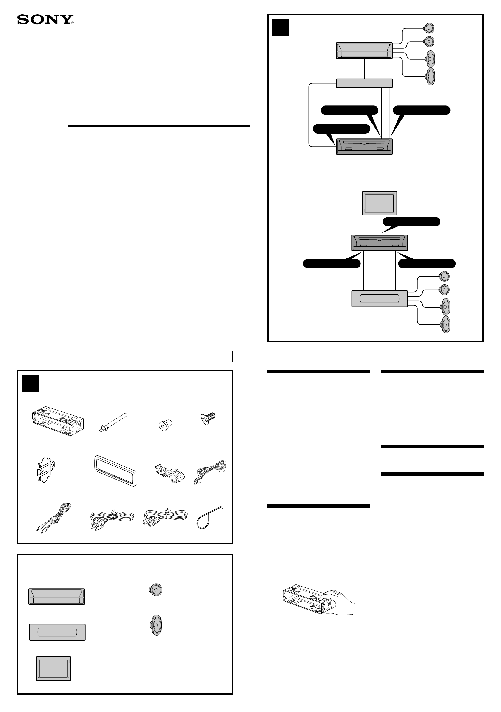
Connection example (2)
This unit must be connected to an optional Sony
master unit with BUS control functions, such as
Media Center/Receiver XAV-7W.
To use the unit with:
— an optional Media Center/Receiver XAV-7W
connected (A).
— an optional monitor and an optional Sony
BUS compatible master unit connected (B).
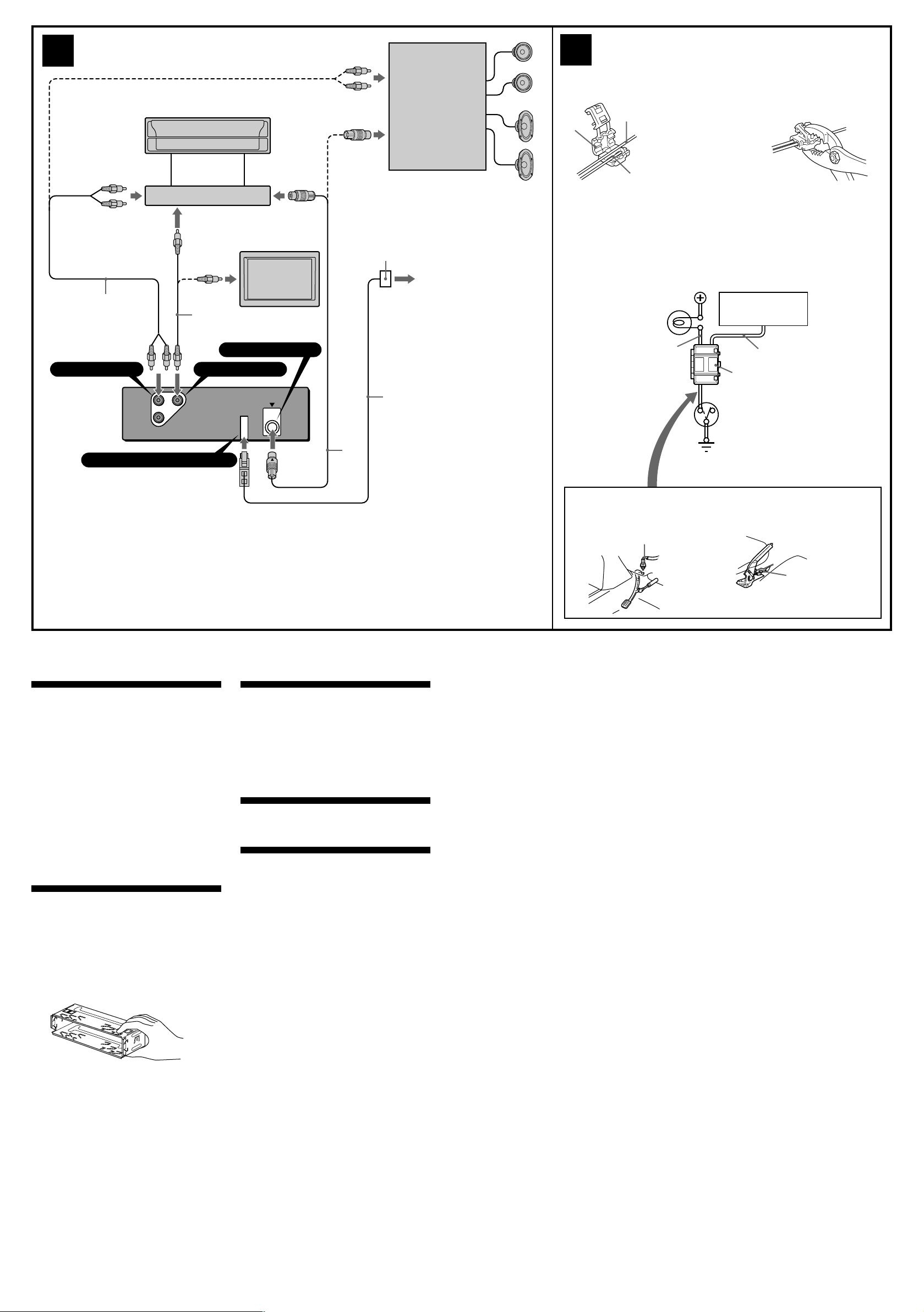
Connection diagram (3)
Connecting the parking brake
cord (4)
Be sure to connect the parking brake cord 8
(light green) to the car’s parking brake switch
cord, whose mounting position depends on your
car. Please consult your car dealer or your
nearest Sony dealer for further details.
Using the pressure terminal
Clasp the end of the parking brake cord 8 (light
green) and the car’s parking brake switch cord
with the pressure terminal 7.
Note
If the car’s parking brake switch cord is too thin,
connect the parking brake cord 8 (light green) to
the car’s parking brake switch cord directly without
using the pressure terminal 7.
Sony BUS compatible
master unit
Sony BUS 相容主機
Monitor
顯示器
Rear speaker
後揚聲器
Page 2
3
Sony BUS compatible
master unit
Sony BUS 相容主機
4
7
Using the pressure terminal 7
使用壓力接頭 7
Car’s parking brake switch cord
停車製動開關導線
c
1
*
q;
BUS AUDIO OUT
L
R
VIDEO OUTAUDIO OUTBUS
Terminal of parking brake cord
9
BUS CONTROL OUT
VIDEO OUT
BUS CONTROL OUT
qa
*
3
7
8
(light green)
(淡綠色)
8
(light green)
(淡綠色)
Connecting the parking brake cord 8 (light green)
連連接停車製動導線 8(淡綠色)
2
*
Car’s parking brake
warning light
停車製動警告燈
Car’s parking brake switch cord
停車製動開關導線
Battery power
蓄電池電源
Car’s parking brake switch
停車製動開關
Body ground
車身接地
CSX-V58MP
7
8
(light green)
(淡綠色)
1
*
Connection BOX (supplied with Media Center/Receiver XAV-7W).
2
*
To car’s parking brake swich cord.
For details, see “Connecting the parking brake cord (4).”
3
*
Connect the BUS cable to its terminal with the unit’s V mark and the BUS cable’s v
mark aligned.
1
*
連接盒(附隨Media Center/Receiver XAV-7W)。
2
*
連接至汽車的停車製動開關導線。詳細說明,請參見“連接停車製動導線
3
*
將總線電纜標有 v 標誌的一端連接至本機標有 V 標誌的端子。
注意
• 本機只能使用負極接地 12 V 直流電源。
• 不要使導線夾在螺栓下,或繞掛在移動部件上
(如:座椅扶手上)。
• 進行連接之前,請先關閉汽車的點火器,以避
免短路。
• 進行連接之前,請仔細閱讀隨本機和選購裝置
一起提供的安裝線路連接手冊。
• 為了安全,請確認把沒有連接的導線用電器膠
帶包紮進行絕緣。
•為了安全,您只能在停車時並使用了停車製動
後,才能觀看連接在 VIDEO OUT 電纜上的監視
器。
請確信將停車製動導線 8(淡綠色)連接至汽
車的停車製動開關導線。
零件一覽表(1)
圖示數字與說明書中的數字是一致的。
取出本裝置需要使用所提供的工具 qs。請參見隨
機附送使用說明書中的“如何取出本裝置”。
注意
移動裝卸支架 1 時,請特別注意別傷到手指。
TOP
(4)
”。
線路連接圖例(2)
本裝置必須連接具有BUS功能的選購裝置Sony主
機,如 Media Center/Receiver XAV-7W。
與下列裝置配合使用:
-選購裝置 Media Center/Receiver XAV-7W,按
照(A)圖連接。
-選購的監視器和選購的 Sony BUS 相容主機,
按照(B)圖連接。
線路連接圖(3)
連接停車製動導線 (4)
必須將停車製動導線 8(淡綠色)連接至汽車的
停車製動開關導線。停車製動開關道線的安裝位
置視您的汽車而定。詳細情況請向您的汽車經銷
商或就近的 Sony 經銷商諮詢。
使用壓力接頭
用壓力接頭 7 將停車製動導線 8(淡綠色)
的末端和停車製動開關導線扣緊。
註
如果停車製動開關導線很細,可不使用壓力接頭
接將停車製動導線
線。
8
(淡綠色)連接至停車製動開關導
7
,直
Foot parking brake type
腳(踏)剎車型
Car’s parking brake
switch cord
停車製動開關導線
Hand parking brake type
手(拉)剎車型
Car’s parking brake
switch cord
停車製動開關導線
Page 3

5
Media Center/Receiver
XAV-7W
Media Center/Receiver
XAV-7W
1
2
3
CSX-V58MP
4
TOP
1
with the TOP marking up
要使帶 TOP 標記面朝上
4
182 mm
53 mm
Dashboard
儀表板
1
TOP
Dashboard
儀表板
Bend these claws outward
for a tight fit, if necessary.
若有必要,則可向外彎曲這些卡爪,
以便牢固安裝。
Fire wall
防火壁
5
6 A TOYOTA
5
54
4
6
with the TOP marking up
要使帶 TOP 標記面朝上
B NISSAN
2
3
max. size
5 × 8 mm
最大尺寸
5×8 mm
4
XAV-7W
Bracket
托架
CSX-V58MP
Existing parts supplied with your car
隨汽車附送的部件
to dashboard/centre console
至儀表板中央控制箱
4
Bracket
托架
max. size
5 × 8 mm
最大尺寸
5×8 mm
max. size
5 × 8 mm
最大尺寸
5×8 mm
4
XAV-7W
Bracket
托架
CSX-V58MP
Existing parts supplied with your car
隨汽車附送的部件
to dashboard/centre console
至儀表板中央控制箱
4
max. size
5 × 8 mm
最大尺寸
5×8 mm
Bracket
托架
Page 4

Precaution
• Choose the installation location carefully so
that the unit will not interfere with normal
driving operations.
• Avoid installing the unit in areas subject to
dust, dirt, excessive vibration, or high
temperatures, such as in direct sunlight or near
heater ducts.
• Use only the supplied mounting hardware for
a safe and secure installation.
Mounting angle adjustment
Adjust the mounting angle to less than 60°.
NTSC/PAL select switch
The TV colour system of this unit is factory-set
to the NTSC position. If the TV colour system of
your country is PAL, set the select switch on the
bottom of the unit to PAL.
Mounting example (5)
Installation in the dashboard
Mounting the unit in a Japanese
car (6)
You may not be able to install this unit in some
makes of Japanese cars. In such a case, consult
your Sony dealer.
Note
To prevent malfunction, install only with the
supplied screws 4.
使用前注意事項
• 仔細選擇安裝位置,使之不妨礙正常的駕駛操
作。
• 避免將本機安裝在多塵、髒亂、易受震動、或
高溫(如陽光直射或加熱器排氣管附近)等地
方。
• 為使安裝安全和可靠,祇能使用提供的安裝零
件。
安裝角度之調整
請在 60 度以內調整安裝角度。
NTSC/PAL選擇開關
本裝置的 TV 彩色系統出廠設定在 NTSC 位置。
如果您國家的 TV 彩色系統是 PAL,請將位於本
裝置底部的選擇開關設定至 PAL。
安裝示例(5)
安裝在儀錶板裡
將本機安裝於日本產汽車上時
(6)
有的日本產汽車不能安裝本機,在這種情形下,
請您向當地的 Sony 經銷商諮詢。
註
為防止發生故障,安裝時只能使用附送的螺絲
4
。
 Loading...