

Page 1
4-086-686-13 (1)
Trinitron Color
Computer Display
Operating Instructions
Mode d’emploi
Manual de instrucciones
US
FR
ES
CPD-E540
© 2001 Sony Corporation
Page 2

Owner’s Record
The model and serial numbers are located at the rear of the unit.
Record these numbers in the spaces provided below. Refer to them
whenever you call upon your dealer regarding this product.
Model No.
Serial No.
WARNING
To prevent fire or shock hazard, do not expose the
unit to rain or moisture.
Dangerously high voltages are present inside the
unit. Do not open the cabinet. Refer servicing to
qualified personnel only.
FCC Notice
This equipment has been tested and found to comply with the limits
for a Class B digital device, pursuant to Part 15 of the FCC Rules.
These limits are designed to provide reasonable protection against
harmful interference in a residential installation. This equipment
generates, uses, and can radiate radio frequency energy and, if not
installed and used in accordance with the instructions, may cause
harmful interference to radio communications. However, there is no
guarantee that interference will not occur in a particular installation.
If this equipment does cause harmful interference to radio or
television reception, which can be determined by turning the
equipment off and on, the user is encouraged to try to correct the
interference by one or more of the following measures:
– Reorient or relocate the receiving antenna.
– Increase the separation between the equipment and receiver.
– Connect the equipment into an outlet on a circuit different from
that to which the receiver is connected.
– Consult the dealer or an experienced radio/TV technician for
help.
You are cautioned that any changes or modifications not expressly
approved in this manual could void your authority to operate this
equipment.
NOTICE
This notice is applicable for USA/Canada only.
If shipped to USA/Canada, install only a UL LISTED/CSA
LABELLED power supply cord meeting the following
specifications:
SPECIFICATIONS
Plug Type Nema-Plug 5-15p
Cord Type SVT or SJT, minimum 3 × 18 AWG
Length Maximum 15 feet
Rating Minimum 7 A, 125 V
NOTICE
Cette notice s’applique aux Etats-Unis et au Canada
uniquement.
Si cet appareil est export* aux Etats-Unis ou au Canada,
utiliser le cordon d’alimentation portant la mention UL LISTED/
CSA LABELLED et remplissant les conditions suivantes:
SPECIFICATIONS
Type de fiche Fiche Nema 5-15 broches
Cordon Type SVT ou SJT, minimum 3 × 18 AWG
Longueur Maximum 15 pieds
Tension Minimum 7 A, 125 V
ENERGY STAR Partner, Sony
As an
Corporataion has determined that this
product meets the
guidelines for energy efficiency.
This monitor complies with the
TCO’99 guidelines.
ENERGY STAR
IMPORTANTE
Para prevenir cualquier mal funcionamiento y evitar daños, por
favor, lea detalladamente este manual de instrucciones antes
de conectar y operar este equipo.
INFORMATION
This product complies with Swedish National Council for Metrology
(MPR) standards issued in December 1990 (MPR II) for very low
frequency (VLF) and extremely low frequency (ELF).
INFORMATION
Ce produit est conforme aux normes du Swedish National Council
for Metrology de décembre 1990 (MPR II) en ce qui concerne les
fréquences très basses (VLF) et extremement basses (ELF).
INFORMACIÓN
Este producto cumple las normas del Consejo Nacional Sueco
para Metrología (MPR) emitidas en diciembre de 1990 (MPR II)
para frecuencias muy bajas (VLF) y frecuencias extremadamente
bajas (ELF).
DISTRIBUIDOR O IMPORTADOR:
Sony Electronicos de Mexico, S.A. de C.V.
Henry Ford No. 29
Fraccionamiento Industrial San Nicolas
Tlalnepantla, Estado de Mexico C.P. 54030
Tel (55)3-21-10-00, RFC SEM-941001-BJA
FABRICANTE:
Sony de Tijuana Este S.A. de C.V.
Laguna Mainar No. 5520, Seccion C
Parque Industrial El Lago
Tijuana, B.C. Mexico C.P. 22570
Tel (664)6-25-32-16, RFC STE-961001-959
(for the Ice Grey color model)
This monitor complies with the
TCO’95 guidelines.
(for the Black color model)
If you have any questions about this product, you may call:
Sony Customer Information Service Center
1-800-222-SONY (7669)
or write to:
Sony Customer Information Center
12451 Gateway Blvd. Ft. Myers, FL 33913 USA
The number below is for FCC related matters only.
Declaration of Conformity
Trade Name: SONY
Model No.: CPD-E540
Responsible Party: Sony Electronics Inc.
Address: 680 Kinderkamack Road, Oradell,
NJ 07649 USA
Telephone No.: 201-930-6972
This device complies with Part 15 of the FCC Rules. Operation
is subject to the following two conditions: (1) This device may
not cause harmful interference, and (2) this device must accept
any interference received, including interference that may
cause undesired operation.
2
Page 3
4
Table of Contents
Setup . . . . . . . . . . . . . . . . . . . . . . . . . . . . . . . . . . . 3
Adjustments . . . . . . . . . . . . . . . . . . . . . . . . . . . . . 4
Troubleshooting . . . . . . . . . . . . . . . . . . . . . . . . . . 6
Specifications . . . . . . . . . . . . . . . . . . . . . . . . . . . . 7
Precautions. . . . . . . . . . . . . . . . . . . . . . . . . . . . . . 8
Appendix . . . . . . . . . . . . . . . . . . . . . . . . . . . . . . . . . i
Preset mode timing table. . . . . . . . . . . . . . . . . . . . . i
Contacting Sony. . . . . . . . . . . . . . . . . . . . . . . . . . . . i
TCO’99 Eco-document
(for the Ice Grey color model) . . . . . . . . . . . . . ii
TCO’95 Eco-document
(for the Black color model) . . . . . . . . . . . . . . .iii
Setup
•Trinitron is a registered trademark of Sony Corporation.
• Macintosh is a trade mark li cense d to A pple Computer , Inc ., r egist ered i n
the U.S.A. and other countries.
• Windows
Corporation in the Unit ed St at es and other countries.
• IBM PC/AT and VGA are reg ist ered trad emar ks of IBM Co rpor at ion o f
the U.S.A.
• VESA and DDC
Association.
ENERGY STAR is a U.S. registered mark.
•
• All other pr oduct names ment ioned herein ma y be the trademarks or
registered trad emarks of their respec tive companies .
• Furthermore, “” and “” are not mentioned in each case in this manual.
and MS-DOS are registered trademarks of Microsoft
are trademarks of the Video Electronics Standards
1 Connecting your monitor to your
computer
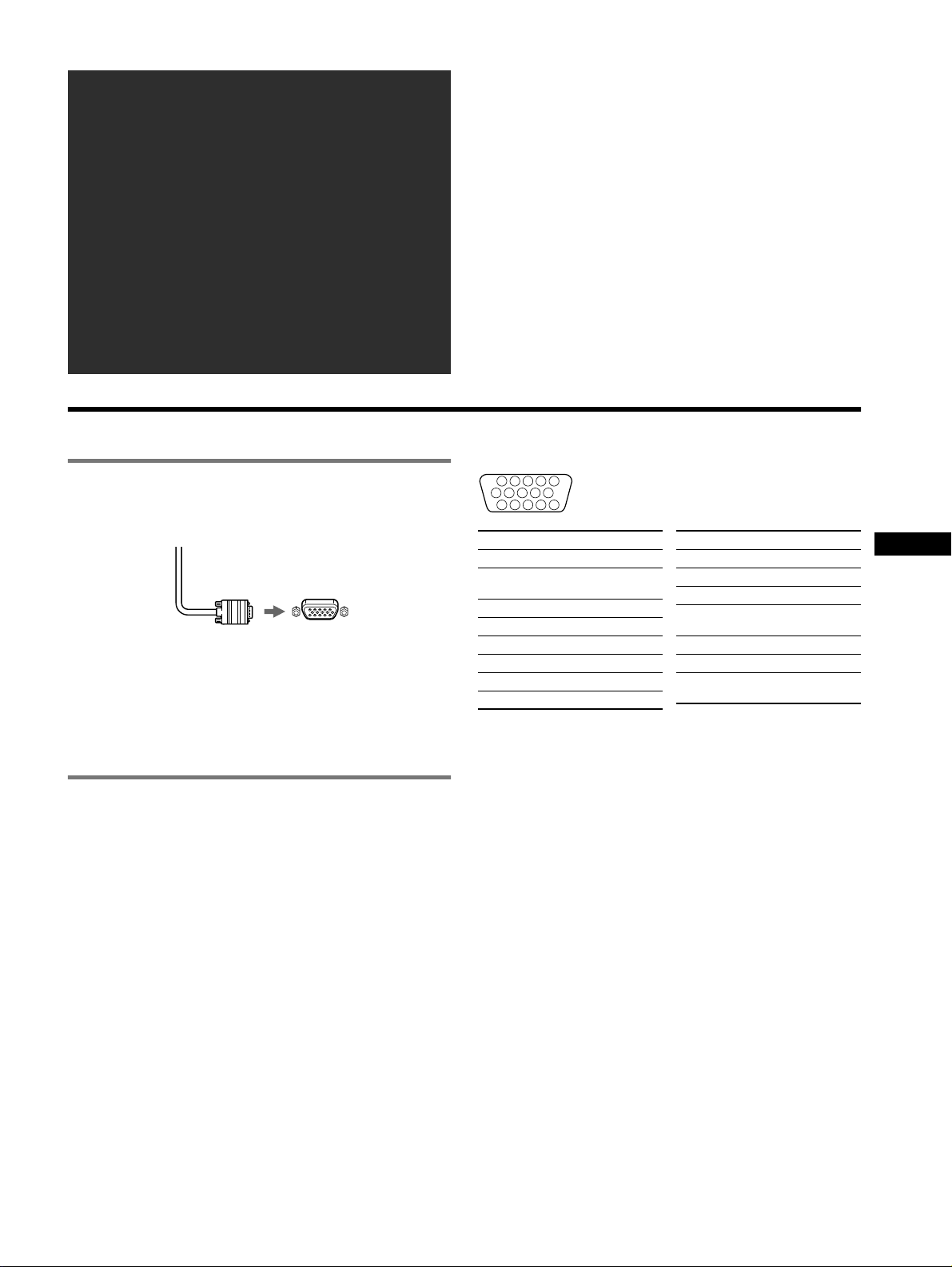
x To connect to the HD15 input connector
Video signal cable
of the monitor
Connecting to a Macintosh or compatible
computer
When connecting this monitor to a Power Mac G3/G4 computer,
use the Macintosh adapter (not supplied) if necessary.
to HD15 of the
connecting computer
2 Turning on the monitor and computer
1 Connect the power cord to the monitor and press the
! (power) switch to turn on the monitor.
2 Turn on the computer.
No need for specific drivers
This monitor complies with the “DDC” Pl ug & Play sta nd ar d and
automatically detec ts all the monitor’s information. No speci fi c dri ve r
needs to be installed to the computer.
The first time you turn on your PC after connecting the monitor, the setup
Wizard may appear on t he sc reen. In this case, fol low the on-screen
instructions. The P lug & Pl ay mon itor is au tomat ical ly sel ected so th at you
can use this monitor.
Notes
• Do not touch the pins of the video signal cable con ne ct or.
• Check the alignment of the HD15 connector to prevent bending the pins
of the video signal cable connector.
The pin assignment of the HD 15 video signal ca ble
1
6 7 8 9 10
11 12 13 14 15
Pin No. Signal
1Red
2 Green (Sync on
3Blue
4 ID (Ground)
5 DDC Ground*
6 Red Ground
7 Green Ground
8 Blue Ground
* DDC (Display Data Channel) is a standard of VESA.
5432
Green)
Pin No. Signal
9 DDC + 5V*
10 Ground
11 ID (Ground)
12 Bi-Directional
Data (SDA)*
13 H. Sync
14 V. Sync
15 Data Clock
(SCL)*
US
3
Page 4

Adjustments
Navigating the menu
1 Press the MENU button to display the main menu.
CONTRAST
/IBR GHT
MENU
,
Main
menu
The horizontal frequen cies /r esolut ion
of the current input sign al (only if the
signal matches to one of this monitor’s
factory preset modes)
CONTRAST
1024x768 / 85Hz
Sub
menu
50
the vertical
frequencies of
the current
input signal
2 Move the control button m/M to highlight the main
menu you want to adjust a nd press the co ntrol b utton.
SZE45/I CENTER
OK
OK
,,
Main
Sub
menu
menu
E
XI T
:
MENU
3 Move the control button m/M to highlight the sub menu
you want to adjust and press the control button.
If you want to select another menu;
move the control button m/M to select and press the control
button to exit the menu.
4 Adjust with the control button.
On-Screen menu adjustments
Main menu icons and adjustme nt
items
Adjusting the contrast and
brightness
Adjusting the size or centering of
the picture
1
*
1
*
Adjusting the shape of the picture
Adjusting the convergence
Sub menu icons and adjustment items
0 RESET: Returns all settings to their factory default settings.
2
*
T
B
0 RESET: Returns all settings to their factory default settings.
Contrast
Brightness
Horizontal position
Horizontal size
Vertical position
Vert ical size
3
Auto Size Center
Rotating the picture
Expanding or contracting the picture sides*
Shifting the picture sides to the left or right*
Adjusting the picture width at the top of the screen*
*
2
*
1
1
1
Shifting the picture to the left or right at the top of the screen*
Horizontally shifts red or bl ue shadows
Vertically shifts red or blue shadows
Vertically shifts red or blue shadows at the top of the screen
Vertically shifts red or blue shadows at the b ottom of the s creen
1
4
Page 5
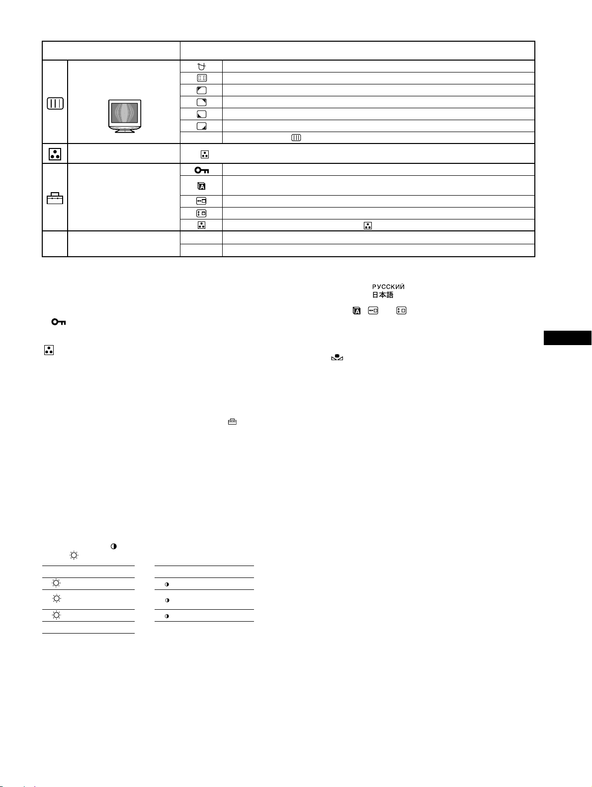
Main menu icons and adjustment
items
Sub menu icons and adjustment items
DEGAUSS: demagnetizes the monitor.
Adjusting the picture qua li ty
Example of Moire
CANCEL MOIRE: adjusts the degree of moire cancellation until the moire is at a minimum.
LANDING: reduces any color irregularities in the screen’s top left corner to a minimum.*
LANDING: reduces any color irregularities in the screen’s top right corner to a minimum.*
LANDING: reduces any color irregularities in the screen’s bottom left corner to a minimum.*
LANDING: reduces any color irregularities in the screen’s bottom right corner to a minimum.*
0 RESET: Returns all settings to their factory default settings.
Adjusting the color of th e pi cture See “ : To adjust the colo r o f th e picture”.
Protecting adjustment data (CONTROL LOCK)
Selecting the on-screen menu language/Confirming the monitor’s information LANGUAGE/
INFORMATION
Additional settings
Changing the menu’s position for horizontal adjustment
Changing the menu’s position for vertical adjustment
Selecting the color adjustment mode (See “ : To ad just the color of the picture.”)
1
Resetting all the adjustment data for the current input signal.*6 Select “OK”.
*
0 R esetting the adjustments
1
*
This adjustment is effec ti ve for th e cu rr ent input signal.
2
*
This adjustment is effective for all input signals.
3
You may not be able to adjust the rotation by the earth magnetic field with
*
01
02
2
Resetting all of the adjustment da ta for al l in put sign al s. Se le ct “OK”.
*
the Auto Size Center function. If you use the Auto Size Center function, all
other size or centering adjust m en ts of th e pi cture are reset.
4
Only the ! (power) switch, MENU button, INPU T sw i tc h, and
*
(CONTROL LOCK) menu will operate.
4
*
5
*
5
Language Menu
*
• ENGLISH • NEDERLANDS: Dutch
• FRANÇAIS: French • SVENSKA: Swedish
• DEUTSCH: German • : Russian
• ESPAÑOL: Spanish • : Japanese
• ITALIANO: Italian
*6The menu items , and are not reset by this method.
1
*
2
2
2
2
: To adjust the color of the picture
The COLOR settings allow you to adjust the picture’s color
temperature by changing th e color level of the white color field.
Colors appear reddish if the temperature is low, and bluish if the
temperature is high. This adjustment is useful for matching the
monitor’s color to a printed picture’s colors.
Select one of the color temperature setting modes from among
4 modes; EASY, PRESET , EXPERT, and sRGB on (OPTION)
menu.
x EASY (Default setting)
You can adjust the color temperature from 5000K to 1100 0K.
x PRESET
You can select the preset color temperature from 5000K, 6500K, or
9300K. The default setting is 9300K.
x EXPERT
You can make additional fine adjustments to the color by selecting
this mode. GAIN ( ) adjusts the bright areas of the screen, while
BIAS ( ) adjusts the dark areas of the screen.
Select for Select for
R R (Red) BIAS R R (Red) GAIN
G
B B (Blue) BIAS B B (Blue) GAIN
0 RESET
G (Green)
BIAS
G G (Green) GAIN
US
To restore the color from the EASY, PRESET, or sRGB
modes ( IMAGE RESTORATION)
You can restore the color to th e original fact ory quality lev els. Before using
this feature, the monitor must have been in normal operation mode (green
power indicator on) for at least 30 minutes. You may need to adjust your
computer’s power saving settings. If the monitor has not been on for at least
30 minutes, the “AVAILABLE AFTER WARM UP” message will appear.
Also, this function may gradually lose its effectiveness due to the na t ura l
aging of the Trinitron picture tube.
x sRGB
The sRGB color setting is an industry sta ndard color space prot ocol
designed to correlate the colors di splayed on the monitor an d those
printed. In order to display the sRGB colors correctly (γ = 2.2,
6500K), select the sRGB mode and your connected computer to the
sRGB profiles. If yo u select sRGB, you cannot o per ate the
CONTRAST/BRIGHT menu adjustments.
5
Page 6

Troubleshooting
x No picture
If the ! (power) indicator is not lit
• Check that the power cord is properly connected.
• Check that the ! (power) switch is in the “on” position.
The ! (power) indicator is orange
• Check that the video signal cable is properly connected and all plugs
are firmly seated in their sockets.
• Check that the HD15 video i nput connector’s pins are not bent or
pushed in.
• Check that the compute r’s power is “on”.
• The computer is in power saving mode. Try pressing any key on the
computer keyboard or moving the mouse.
• Check that the graphic board is completely seated in the proper bu s
slot.
If the ! (power) indicator is green or flashing orange
• Use the Self-diagnosis function.
x Picture flickers, bounces, oscillates, or is scrambled
• Isolate and eliminate an y potential sources of electric or magnetic
fields such a s other moni tors, la ser print ers, el ectric fan s, fluore scent
lighting, or televis io ns .
• Move the monitor away from power lines or place a magn etic shield
near the monito r.
• Try plugging the monitor into a dif fe rent AC o utl et , p re fer ably o n a
different circuit.
• Try turning the monitor 90° to the left o r right.
• Check your graphics board m anual for the proper mo ni t or set t in g.
• Confirm that the graphics mode and the frequency of the input signal
are supported by this monitor (see “Preset mode timing table” on
page i). Even if the fr equency is within the proper range, some
graphics board may have a sync pulse that is to o narrow for the
monitor to sync correctly.
• Adjust the computer’s refresh rate (vertic al frequency) t o obtain the
best possible picture.
x Picture is fuzzy
• Adjust the contrast an d br i ghtness.
• Degauss the monito r. *
• Adjust the degree of moire cancellation until the moire is minimal,
or set CANCEL MOIRE to OFF.
x Picture is ghosting
• Eliminate the use of video cable extensions and/or video switch
boxes.
• Check that all plugs are firmly seated in their sockets.
x Picture is not centered or sized properly
• Perform the Auto Size Ce nt er function.
• Adjust the si ze or cente ring. Note that with so me input signals and/
or graphics board the periphery of th e screen is not fully utilized.
• Just after turning on the power switch, the size/center may take a
while to adjust properly.
x Picture is rotating
• Refer to “ Notes on correc ting pic ture rotati on caused by orie ntati on
of the monitor with respect to the earth magnetic field.”
x Edges of the image ar e curved
• Adjust the geometry.
x Wavy or elliptical pattern (moire) is visible
• Adjust the degree of moire cancellation until the moire is minimal.
• Change your desktop patt er n.
x Color is not uniform
• Degauss the monitor. * If you place equipm ent that generates a
magnetic field, such as a speaker, near the monitor, or if you change
the direction the monitor faces, color may lose uniformity.
• Adjust the la nding.
x White does not look white
• Adjust the color temp erature.
x Monitor buttons do not operate ( appears on the
screen)
• If the control lock is set to ON, set it to OFF.
x Letters and lines show red or blue shadows at the
edges
• Adjust the conver gence.
x A hum is heard right after the power is turned on
• This is the sound of th e auto-degauss cyc le . W h en the power is
turned on, the monitor is automa tical ly dega ussed for a few se conds.
* If a second degauss cycle is needed, a llo w a minimum interval of
20 minutes for the best result. A humming noise may be heard, but this is
not a malfunction.
On-screen messages
IIONNFORMAT
MON I I INGS WORKTOR
NPUT
I
ACT
I VATE
S GNAL CABLEI
CHECK
1 If “NO SIGNAL” appears:
This indicates that no signal is input.
2 Shows the remedies.
• If ACTIVATE BY COMPUTER appears on the screen, try
pressing any key on the computer or moving th e mouse, and
confirm that your computer’s graphic board is comp letely seat ed
in the correct bus slot.
• If CHECK SIGNAL CABLE appears on the screen, check that
the monitor is correctly connected to the computer.
IIONNFORMAT
MON I I INGS WORKTOR
NPUT
I:.200 0 /kHz 85Hz
OUT OF SCAN
CHANGE
S GNAL TIIINGM
1 If “OUT OF SCAN RANGE” appears:
This indicates that the input signal is not sup ported by the monitor’s
specifications.
2 Shows the input signal frequency.
3 Shows the remedies.
CHANGE SIGNAL TIMING appears on the screen. If you are
replacing an old monitor with this monitor, reconnect the old
monitor. Then adjust the computer’s graphic board so that the
horizontal frequency is between 30 – 110 kHz, and the vertical
frequency is between 48 – 170 Hz.
:NOBYS
RANGE
GNALI
COMPUTER
W
R
G
B
W
R
G
B
6
Page 7

To display this monitor’s name, serial number, and
date of manufacture.
While the monitor is receiving a
video signal, press an d hold the
MENU button for more than
5 seconds to display this
monitor’s information box.
INFORMATION
MODEL : CPD E540
SER NO : 1234567
MANUFACTURED
: 2001-52
W
R
G
B
If thin lines appear on the screen
(damper wires)
These lines do not indicate a malfunction; they are a normal
effect of the Trinitron picture tube with this monitor. These are
shadows from the damper wires used to stabilize the aperture grille.
The aperture grille is the essential element that makes a Trinitron
picture tube unique by allowing more light to reach the screen,
resulting in a brighter, more detailed picture.
Damper
wires
Self-diagnosis function
This monitor is equipped with a self-diagnosis functio n. If th ere is
a problem with your monitor or com puter, the screen will go blan k
and the ! (power) indicator will either light up green or flash
orange. If the ! (power ) indi cato r is lit in oran ge, th e compu te r is
in power saving mode . Try pressing any key on the keyboard or
moving the mouse.
x If th e ! (power) indicator is green
1 Disconnect the video signal cable, or turn off the
connected computer.
2 Turn the monitor OFF and then ON.
3 Hold the control button upward for a few seconds
before the monitor enters power saving mode.
If all 4 color bars appear (white, red, green, blue), the monitor is
working properly. Reconnect the video input cables and check the
condition of your computer.
If the color bars do not appear, there is a potential monitor failure.
Inform your authorized Sony deal er of the monitor’s condition.
Specifications
CRT
0.24 mm aperture grille pi tc h, 90-degree deflection, FD Tri nit ron
21 inches measured diagonally
Viewable image size
Resolution (H:Horizontal, V:Vertical)
Input signal levels
Video signal: Analog RGB: 0.700 Vp-p (positive), 75 Ω
SYNC signal: H/V separate or composite sync:
Standard image area
Deflection frequency*
AC input voltage/current
Power Consumption
Operating temperature
Dimensions Approx. 497 × 502 × 485 mm (w/h/d)
Mass Approx. 30 kg (66 lb 2 oz)
Plug and Play D DC2B/DDC2Bi, GTF**
Supplied accessories
* Recom m ended horizontal and ver ti ca l t im ing condition
• Horizontal sync width duty should be more than 4.8% of total
horizont al time or 0.8 µs, wh ic hever is larger.
• Horizontal blanki ng w id th should be more than 2.3 µsec.
• Vertical blankin g w idt h should be more than 450 µsec.
** If the input signal is Generali zed Timin g Formula (GTF) comp liant, the
GTF feature of the mon itor will automati cally prov ide an opti mal image
for the screen.
Approx. 403.8 × 302.2 mm (w/h) (16 × 12 inches)
19.8" viewing image
Maximum: H: 2048 dots, V: 1536 lines
Recommended: H: 1600 dot s , V: 12 00 l ine s
TTL 2 kΩ, Polarity free
Sync on Green: 0.3 Vp-p (negativ e)
Approx. 388 × 29 1 mm
3
/8 × 11 1/2 inches) or
(15
Approx. 364 × 29 1 mm
3
/8 × 11 1/2 inches)
(14
(H:Horizontal, V:Vertical)
H: 30 to 110 kHz, V: 48 to 170 Hz
100 to 240 V, 50 – 60 Hz, 2.0 – 1.0 A
Approx. 135 W
10 ºC to 40 ºC
5
/8 × 19 × 18 7/8 inches)
(19
Power cord
Warranty card
This instruction manual
US
x If th e ! (power) indicator is flashing orange
Turn the monitor OFF and then ON.
If the ! (power) indicator lights up green, the monitor is working
properly.
If the ! (power) indicator is still flashing, there is a potential
monitor failure. C ount the number of seconds between orange
flashes of the ! (power) ind icator and i nform your au thorized Sony
dealer of the monitor’s condition. Be sure to note the model name
and serial number of your monitor. Also note the make and model
of your computer and graphics board.
Note
If you still have questions, please se e Appendix for contacting Sony.
(continued)
7
Page 8

Preset and user modes
When the monitor receives an input signal, it automatically matches the
signal to one of the factory preset modes stored in the monitor’s memory
to provide a high quali ty pi ct ure
page i)
. If the input signals does not match one of th e fa ct ory preset
modes, the monitor automatically provides the most appropriate picture
for the input signal that is wit hi n the range of the vertical or ho ri zontal
frequencies (page 7) corre sponding to the Generalized Timing Formula.
When the picture is adjusted, the adjustment data is stored as a user mode
and automatically recalled whenever the same input signal is received.
Power savi ng function
This monitor meets the power-saving guidelines set by VESA, ENERGY
(see “Preset mode timing table” on
STAR, and NUTE K . If no signal is in put to the monitor from you r
computer, the monitor will automatically reduce power consumption as
shown below.
Power mode Power consumption ! (power)
normal operation ≤ 135 W green
active off*
(deep sleep)*
power off Approx. 0 W off
1
*
2
*
Design and specifications are s ubject to change wi thout notice.
1
When your computer enters power saving mode, NO SIGNAL appears
on the screen. After a few seconds, the monito r ent ers power savi ng
mode.
“Deep sleep” is power saving mode defined by the Environmental
Protection Agency.
≤ 3 W orange
2
indicator
Precautions
Warning on power connections
• Use the sup plied po wer cord. I f you use a di fferent power cord ,
be sure that it is compatible with your local power supply.
For the customers in the U.S.A.
If you do not use the appropriate cord, this monitor will not
conform to mandatory FCC standards.
Example of plug types
for 100 to 120 V AC for 200 to 240 V AC
• Before disconnecting the power cord, wait at least 30 secon ds
after turning off the power to allow the stat ic elec tricity on the
screen’s surface to discharge.
• After the power is turned on, the screen is demagnetized
(degaussed) for about a few seconds. This generates a strong
magnetic field around the screen which may affect data stored
on magnetic tapes and disks placed near the monitor. Be sure to
keep magnetic recording equipment, tape s , an d dis k s away
from the monitor.
The equipment should be instal led near an easily accessible
outlet.
Installation
Do not install the monitor in the following places:
• on surfaces (rugs, blankets, etc.) or near materials (curtains,
draperies, etc.) that may block the ventilation holes
• near heat sources such as radiators or air ducts, or in a place
subject to dire ct sunlight
• in a place subject to severe temperature changes
• in a place subject to mechanical vibration or shock
• on an unstable surface
• near equipment which generates magn etism, such as a
transformer or high volta ge po wer line s
• near or on an electrically charged metal surface
• inside an enclosed rack
Protection
• Do not put foreign object s into the monito r.
• Disconnect the monitor if environment exceeds 60°C/140°F.
• Ensure AC power cord is not trapped under furniture, TV, etc.
• Do not overload wall outlets, extension cords, or convenience
receptacles beyond their capaci t y.
• Never spill liquid of any kind on the monitor.
Notes on cleaning the screen’s surface
• The screen’s surface is covered with a thin anti-reflective
coating to enhance the ergonomic characteristics of the
monitor. To ensure that the coating is not damaged, use a soft
cloth to clean the screen’s surface. If necessary, use a soft cloth
lightly moistened with a mild detergent solution, such as hand
soap, to wipe the screen.
• Do not use any type of abrasive pad, alkaline cleanser, scouring
powder, or solvents such as alcohol or benzene as they might
damage the anti-reflective coating.
• If you use a glass cleaning liquid, do not use any type of cleaner
containing an anti-static solutio n or similar additive as this may
scratch the screen’s coating.
• Do not rub, touch, or tap the surface of the screen with sharp or
abrasive items such as a ballpoint pen or screwdriver. This type
of contact may result in a scratched picture tube.
Notes on cleaning the cabinet
• Clean the cabinet, panel and controls with a soft cl oth lightly
moistened with a mild detergent solution.
• Do not use any type of abrasive pad, scouring powder or
solvent, such as alcohol or benzene.
8
Page 9

Transportation
When you transport this monitor for repair or shipment, use the
original carton and packing materials.
Use of the tilt-swivel
This monitor can be adjusted within the angles shown right. To find
the center of the monitor’s turning radius, align the center of the
monitor’s screen with the centering dot on the stand.
Hold the monitor at the bottom with both hands when you turn it
horizontally or vertically. Be c areful not to pinc h your fing ers at the
back of the monitor when you tilt the monitor up vertically.
90°
15°
90°
5°
Centering dot
US
9
Page 10

Page 11

Table des Matières
Configuration. . . . . . . . . . . . . . . . . . . . . . . . . . . . . . . 3
Réglages. . . . . . . . . . . . . . . . . . . . . . . . . . . . . . . . . . . 4
Dépannage. . . . . . . . . . . . . . . . . . . . . . . . . . . . . . . . . 6
Spécifications . . . . . . . . . . . . . . . . . . . . . . . . . . . . . . 7
Précautions . . . . . . . . . . . . . . . . . . . . . . . . . . . . . . . . 8
Appendix . . . . . . . . . . . . . . . . . . . . . . . . . . . . . . . . . . . i
Preset mode timing table . . . . . . . . . . . . . . . . . . . . . . . i
Contacting Sony
. . . . . . . . . . . . . . . . . . . . . . . . . . . . i
TCO’99 Eco-document
(for the Ice Grey color model) . . . . . . . . . . . . . ii
TCO’95 Eco-document
(for the Black color model) . . . . . . . . . . . . . . .iii
Configuration
• Trinitron est une marque commerciale déposée de Sony Corporation.
• Macintosh est une ma rque comme rciale s ous lic ence d ’Apple Comp uter, Inc.,
déposée aux Etats-Unis et dans d’autres pays.
•Windows
aux Etats-Unis et dans d’autres pays.
• IBM PC/AT et VGA sont des marques commerciales déposées d’IBM
Corporation aux Etats-Unis.
• VESA et DDC
Standards Association.
ENERGY STAR est une marque déposée aux Etats -Un is.
•
• Tous les autres noms de produits mentionnés dans le présent mode d’emploi
peuvent être des marques commerciales ou des marques commerciales
déposées de leurs sociétés respectives.
• Les symboles “” et “” ne sont pas mentionnés systématiquement dans le
présent mode d’emploi.
et MS-DOS sont des marques déposées de Microsoft Corporation
sont des marques commerciale s de Vide o Ele c tr oni cs
1 Raccordez votre moniteur à votre
ordinateur
x Raccordement au connecteur d’entrée HD15
Câble de signal vidéo
du moniteur
Raccordement à un Macintosh ou un ordinateur
compatible
Lorsque vous raccordez ce moniteur à un ordinateur Power Mac
G3/G4, utilisez l’ adaptateur Macintosh (non fourni) , l e cas échéant.
vers le HD15 de
l’ordinateur raccordé
2 Mettez le moniteur et l’ordinateur sous
tension
1 Raccordez le cordon d’alimentation au moniteur puis
appuyez sur l’interrupteur ! (alimentation) afin de mettre
le moniteur sous tension.
2 Mettez l’ordinateur sous tension.
Vous n’avez pas besoin de pilotes spécifiques
Ce moniteur est conforme à la norme Plug & Play “DDC” et détecte
automatiquement l’ensemble des informations relatives au moniteur. Il n’est pas
nécessaire d’installer un pilote spécifique sur l’ordinateur .
Lorsque vous mettez votre ordin at eu r so us te nsion pour la première fois, après
l’avoir raccordé au moniteur, il est possible que l’Assistant d’ajout de nouveau
matériel apparaisse à l’écran. Dans ce cas, suivez les instructions affichées. Le
moniteur Plug & Play approprié est sélectionné automatiquement, vous
permettant ainsi de l’utiliser.
Remarques
• Ne touchez pas les broche s du c onne c te ur du câble de signa l vi dé o.
• Vérifiez l’alignement du connecteur HD15 pour ne pas tordre les broches du
connecteur du câble de signal vidéo.
Configuration des broches du c â ble de si gnal vidéo HD 15
1
6 7 8 9 10
11 12 13 14 15
N° de broche Signal
1 Rouge
2Vert
3Bleu
4 ID (Masse)
5 DDC (Masse)*
6 Masse Rouge
7Masse Vert
8Masse Bleu
* DDC (Display Data Channel) est une norme de VESA.
5432
(Sync sur Vert)
N° de broche Signal
9 DDC + 5V*
10 Masse
11 ID (Masse)
12 Données
bi-directionnelles
(SDA)*
13 Sync H
14 Sync V
15 Horloge de
données (SCL)*
FR
3
Page 12

Réglages
Navigation dans le menu
1 Appuyez sur la touche MENU pour afficher le menu
principal.
CONTR
/LUM I N
MENU
CONTRASTE
,
1024x768 / 85Hz
Menu principal
fréquences horizontales/résolution du
signal d’entrée courant (uniquement si
le signal correspond à l’un des modes
prédéfinis en usine de ce moniteur)
Sous-menu
50
fréquences
verticales du signal
d’entrée courant
2 Déplacez la touche de commande m/M pour mettre en
surbrillance le menu principal que vous souhaitez régler
et appuyez sur la touche de com m ande.
LL
TI
/A CENTRAGE
OK
OK
,,
Menu principal
Sous-menu
45
SORT
IR
:
3 Déplacez la touche de commande m/M pour mettre en
surbrillance le sous-menu que vous souhaitez régler, puis
appuyez sur la touche de comm and e.
Si vous souhaitez sélectionner un autre menu ;
déplacez la touch e de commande m/M po ur sélectionner , puis
appuyez sur la touche de commande pour quitter le menu.
4 Effectuez le réglage à l’aide de la touche de commande.
MENU
Réglages du menu d’écran
Icônes du menu principal et éléments
de réglage
Réglage du contraste et de la
luminosité
Réglage de la taille ou du centrage
de l’image
Réglage de la forme de l’image
Réglage de la convergence
1
*
1
*
*
Icônes du sous-menu et éléments de réglage
0 REINITIALISATION : Les réglages sont tous réinitialisés sur les valeurs par défaut.
2
0 REINITIALISATION : Les réglages sont tous réinitialisés sur les va leurs par défaut.
Contraste
Luminosité
Position horizontale
Taille horizontale
Position verticale
Taille verticale
Centrage de taille au tom atique
Rotation de l’image
Étirement ou contraction des c ôtés de l’image*
Déplacement des bords de l’image vers la droite ou la gauche*
Réglage de la largeur de l’image en haut de l’écran*
Déplacement de l’image vers la droite ou la gauche en haut de l’écran*
Décalage horizontal des ombres ro uge s ou ble ue s
Décalage vertical des ombres rouges ou bleu e s
Décalage vertical des ombres rouges ou bleue s e n hau t de l’écran
T
B
Décalage horizontal des ombres rouge s ou ble u e s en bas de l’écran
2
*
3
*
1
1
1
1
4
Page 13

Icônes du menu principal et éléments
de réglage
Réglage de la qualité de l’image
Exemple de moiré
Réglage de la couleur de l’image Voir “ : pour régler la couleur de l’image”.
Réglages supplémentaires
0 Réinitialisation des réglages
1
Ce réglage est effectif p our le signal d’entrée courant.
*
2
*
Ce réglage est effectif pour to u s les autres signaux d’entrée.
3
Il est possible que vous ne puissiez pas régl er la rotat ion due au champ
*
magnétique terrestre à l’aide de la fonction Centrage automatique de la taille.
Si vous utilisez la fonction Cent rage au tomatique de la taille, tous les autre s
réglages de taille ou de centrage de l’image sont réinitialisés.
4
Seuls l’interrupteur ! (alimentation), la touche MENU, l’interrupteur INPUT et
*
le menu (VERROU MENU) fonctionneront.
Icônes du sous-menu et éléments de réglage
DEMAGNET : démagnétise le moniteur.
SUPPRESSION MOIRAGE : règle le degré de suppression du moiré a fin de réduire le moiré au
minimum.
PURETE COULEUR : réduit au minimum les irrégularités des couleurs dans l’angle supérieur gauche
de l’écran.
PURETE COULEUR : réduit au min imu m le s irr égularités des couleurs dans l’angle supérieur droit de
l’écran.
PURETE COULEUR : réduit au minimum les ir r égularités des couleurs dans l’angle inférieur gauche
de l’écran.
PURETE COULEUR : réduit au minimum les irrégularités des couleurs dans l’angle inférieur droit de
l’écran.
0 REINITIALISATION : Les réglages sont tous réinitialisés sur les valeurs par défaut.
Protection des données de réglage (VERROU MENU)
Sélection de la langue d’affichage à l’écr an/Confirmation des inform ations relatives au moniteur
LANGUAGE/INFORMATIONS
Modification de la position du menu pour le réglage hor iz ont al
Modification de la position du menu pour le réglage vertical
Sélection du mode de réglage des couleurs. (Voir “ : pour régler la couleur de l’image”.)
Réinitialisation de l ’ensemble des données de réglage pour le signal d’entrée actuel.*
1
01
*
“OK”.
Réinitialisation de l ’ensemble des données de réglage pour tous les sig naux d’entrée. Appuyez sur
2
*
02
“OK”.
1
*
2
*
2
*
2
*
2
*
4
*
5
*
6
Appuyez sur
5
Menu de langues
*
• ENGLISH : Anglais • NEDERLANDS : Néerlandais
• FRANÇAIS • SVENSKA : Suédois
• DEUTSCH : Allemand • : Russe
• ESPAÑOL : Espagnol • : Japonais
• ITALIANO : Italien
*6Les options de menu , et ne sont pas réinitialisées par cette
méthode.
FR
: pour régler la couleur de l’image
Les paramètres COU LEUR permettent de régler la température des
couleurs de l’image en changeant le niveau de couleur des champs de
couleur blanche. Les couleurs appar ai ssent rougeâtres lorsque la
température est basse et bleuâtres lorsqu’elle est élevée. Ce réglage
s’avère pratique pour faire correspondre les couleurs du moniteur aux
couleurs d’une im age imprimée.
Sélectionnez l’un des modes de réglage de te mpérature des couleurs
parmi les 4 modes; SIMPLE, PRESELECT, EXPERT et sRGB dans le
menu (OPTION).
x SIMPLE (Réglage par défaut)
Vous pouvez régler l a température des couleurs sur une plage comprise
entre 5000K et 11000K.
x PRESELECT
Vous pouvez sélectionner une température des couleurs prédéfinie, à
savoir 5000K, 6500K , ou 9300K. Le réglage par défaut est 9300K.
x EXPERT
Vous pouvez ef fectuer des réglages affinés supplément a i res des
couleurs en sélect io nnant ce mode. GAIN ( ) règle les zones
lumineuses de l’écran, alors que BIAS ( ) règle les zones sombres.
Sélectionnez pour Sélectionnez pour
R R (Rouge) BIAS R
GG (Vert) BIASG G (Vert) GAIN
B B (Bleu) BIAS B
0 REINITIALISATION
R (Rouge) GAIN
B (Bleu) GAIN
x sRGB
Le réglage de couleur sRGB est un proto col e industriel standard pour
les espaces colorimétriques. Il est conçu pour harmoniser le s couleurs
affichées sur le moniteur et les couleurs imprimées . Pour afficher les
couleurs sRG B cor rectement (
γ = 2,2, 6500K), sélectionnez le mode
sRGB et réglez l’ordinateur raccordé sur les profils sRGB. Il est
impossible d’utiliser les réglages du menu CONTR/LUMIN. lorsque
vous sélectionnez le mode sRGB.
Restauration des couleurs via les modes SIMPLE, PRESELECT
ou sRGB ( RESTAURER COULEUR)
Vous pouvez restaurer les couleurs par défaut, afin de retrouver les niveaux de
qualité initiaux. Le moniteu r do it a voir f onc tionné normalement (indicateur
d’alimentation vert al lumé) pendant au moins 30 minutes avant d’utiliser cette
fonction. Vous devrez peut-être régler les paramèt res du m ode d’économie
d’énergie de votre ordinateur. Si le moniteur n’a pas fonctionné depuis au moins
30 minutes, le message “UTILISABLE APRES CHAUFFAGE” s’affiche. De
même, il se peut que cette fonction per de de son e fficacité en raison du
vieillissement natu r e l du tube à image Trinitron.
5
Page 14

Dépannage
x Aucune image
Si l’indicateur ! (alimentation) est éteint
• Assurez-vou s qu e le cordon d’alimentation est raccordé correctement.
• Vérifiez que l’interrupteur ! (alimentation) est en position ac ti vée (on).
L’indicateur ! (alimentation) est allumé en orange
• Vérifiez que le câble de signal vidéo est correctement raccordé et que
toutes les prises sont complètement enfichées.
• Vérifiez que les bro ches du c onn ect eur d’entrée vidéo HD15 ne sont pas
pliées ni enfoncées.
• Assurez-vous que l’ordinateur est s ous tension.
• L’ordinateur es t en mode d’économie d’énergie. Essayez d’appuyer sur
une touche ou de déplacer la souris.
• Vérifiez que la ca rte gr aphique est bien insérée dans le connecteur de bus
approprié.
Si l’indicateur ! (alimentation) est vert ou orange clignotant
• Utilisez la f onction d’auto-diagnostic.
x L’image scintille, sautille, oscille ou est brouillée
• Isolez et supprimez les sources potentiell es de cha m ps él ec t riq ues ou
magnétiques tels que d’autres moniteurs, des imprimante s laser, des
éclairages fluorescen ts ou des téléviseurs.
•Éloignez le moniteur des lign es à haute tensi on ou placez un blin dage
magnétique à proximité du moniteur.
• Banchez le moniteur sur une autre prise secteur, de préférence raccordée
à un autre circuit.
• Faites pivoter le moniteur de 90° vers la gauche ou l a dro it e.
• Vérifiez le réglage adéquat pour le moniteur dans le mode d ’e mp loi de
votre carte graphique.
• Assurez-vous que le mode graph iqu e et la fréquence du signal d’entrée
sont pris en charge par ce moniteur (voir le tableau de modes prédéfinis
(Preset mode timing table) page i). Même si la fréquence est compr is e
dans la plage appropriée, il est possible que certaines cartes graphiques
aient une impulsion de synchronisation trop étroite pour que le moniteur
puisse se synchroniser correctement.
• Ajustez le taux de régénération de l’ordinateur (fréquence verticale) de
façon à obtenir la meilleur e ima ge possible.
x L’image est floue
• Réglez le contras t e et la luminosité.
• Démagnétisez le moniteur.*
• Réglez le degré de suppression du moi ré afin de réduir e le moiré au
minimum ou réglez SUPPRESSION MOIRAGE sur INACTIF.
x Des images fantôme s apparaissent
• N’utilisez pas de prolongat e urs de câble vidéo et/ou de boîtiers de
commutation vidéo.
• Vérifiez que toutes les fiches sont bien connectées dans le ur s prises
respectives.
x L’image n’est pa s ce ntr ée ou est de taille incorrecte
• Exécutez le Centr age de taille automatique.
• Ajustez la taille ou le centrage. Veuillez noter que pour certains signaux
d’entrée et/ou cartes gra phi qu es, i l e st po ss ibl e que l’im age n e r empli sse
pas totale ment la surfa ce de l’écran.
• Juste après la commutation de l’interrupteur d’alimentation, le réglage
correct de la taille et du centrage peut prendre un certain temps.
x L’image est inclinée
• Reportez-vous au document “Remarque concernant la correction de
rotation de l’image provoq uée par l’orientation du moniteur pa r ra pport
au champ magnétique terrestre”.
x Les bords de l’image sont incurvés
• Réglez la géométrie.
x Un motif ondulatoire ou elliptique (moiré) est visible
• Réglez le degré de suppression du moi ré afin de réduir e le moiré au
minimum.
• Changez le motif de votre bureau.
x Les couleurs ne sont pas uniformes
• Démagnétisez le moniteur.* Si vous placez à côté du monit eur un
appareil qui génère un champ magnétique, comme un haut -pa rle ur, ou s i
vous changez l’orient at io n du moniteur, il est possible que les couleurs
perdent leur uniformité.
• Réglez l’alignement.
x Le blanc n’est pas blanc
• Réglez la te mpérature des couleurs.
x Les touches du moniteur ne fonctionnent pas
( apparaît à l’écran)
• Si la fonction de verrouillage des commandes est réglée sur ACTIF,
réglez-la sur INACTIF.
x Les bords des lettres et des lignes sont soulignés d’une
ombre rouge ou bleue
• Réglez la conver ge nce.
x Un bourdonnement est audible juste après la mise sous
tension
• Il s’agit du son provoqué par le cycle de démagnétisation automa tique.
Lorsque le moniteur est mis sous tension, il est automatiquement
démagnétisé pendant quelques secondes.
* Si un deuxième cycle de démagnétisation est nécessai re, attendez au
minimum 20 minutes pour un résultat optimal. Un bourdonnement peut être
audible, ceci est normal.
Messages à l’écran
IIONSNFORMAT
L ' ECRAN FONCT I ONNE
ENTREE
ACT I VER PAR L ' ORD I NATEUR
VER I F I ER CABLE V I DEO
1 Si “PAS DE VIDEO” s’affiche :
Ceci indique qu’aucun signal n’est reçu.
2 Indique les remèdes.
• Si le message ACTIVER PAR L’ORDINATEUR apparaît à l’écran,
essayez d’appuyer sur une touche que l conque du clavier ou de
déplacer la souris et a ss urez-vous que la cart e gr aphique est
correctement et totalement insérée dans le connecteur de bus
adéquat.
• Si le message VERIFIER CABLE VIDEO apparaît à l’écran,
vérifiez que le moniteur est connecté correctement à l’ordinateur.
I I ONSNFORMAT
L ' ECRAN FONCT I ONNE
ENTREE
HORS PLAGE DE BALAYAGE
CHANGE S I GNAL PARAMETRE
1 Si “HORS PLAGE DE BALAYAGE” s’af fiche :
Ceci indique que le si gnal d’entrée n’est pas pris en charge par les
spécificati ons du moniteur.
2 Affiche la fréquence du signal d’entrée.
3 Indique les remèdes.
Le message CHANGE SIGNAL PARAMETRE apparaît à l’écran. Si
vous remplacez votre ancien moni te ur par ce moniteur, rebranchez
l’ancien moniteur. Ajustez ensuite la carte graphique de l’ordinateur de
sorte que la fréquence horizontale soit co m prise entre 30 et 110 kHz ,
et que la fréquence vert i cal e soit comprise entre 48 et 170 Hz.
:PAS DE V I DEO
:.200 0 /kHz 85Hz
W
R
G
B
W
R
G
B
6
Page 15

Affichage de l’identification du moniteur, du
numéro de série et de la date de fabrication.
Alors que l’écran reçoit un signal
vidéo, maintenez la touche
MENU enfoncé pendant plus de
5 secondes pour affic her les
informations sur ce moniteur.
I NFORMAT I ONS
MODEL : CPD E540
SER NO : 1234567
MANUFACTURED
: 2001-52
W
R
G
B
Si des lignes fines apparaissent à
l’écran
Ces lingnes ne co nstituent aucunement un dysfonctionnement;
elles résultent de l’utilisation du tube i mag e Tr ini tron sur ce moniteur.
Ces lignes sont en fait l’ombre des fils d’amortissement employés pour
stabiliser la grille d’ouverture. Cette grille est un composant essentiel
qui rend le tube d’image Trinitron unique en laissant passer une plus
grande quantité de lumière vers l’écran, permettant ainsi d’obtenir une
image plus lumi neuse et plus détaillée.
(fils d’amortissement)
Fils d’amortissement
Fonction d’auto-diagnostic
Ce moniteur est équipé d’une fonction d’auto-diagnostic. En cas de
problème avec votre moniteur ou vo t re ordinateur, rien n’est affiché à
l’écran et le témoin ! (alimentat ion) s’allume en vert ou clignote en
orange. Si l’indicateur ! (alimentation) est allumé en orange,
l’ordinateur e st e n m ode d’économie d’énergie. Essayez d’appuyer sur
une touche ou de déplacer la souris.
x Si l’indicateur ! (alimentation) s’allume en vert
1 Débranchez le câble de sign al vidéo ou mettez
l’ordinateur raccordé hors tension.
2 Et eigne z, puis ra llume z le monit eur.
3 M aint en ez le bouton de commande vers le haut pendant
quelques secondes avant que le moniteur n’entre en
mode d’économie d’énergie.
Si les quat re barres d e couleurs apparais sent (bla nc, roug e, vert et bleu),
le moniteur fonctionne correctement. Rebranchez les câbles d’entrée
vidéo et vérifiez l’état de votre ordinateur.
Si les barres de couleur n’apparaissent pas, il est possibl e que le
moniteur ne fon ct io nne pas normalement. Informez vot re revendeur
Sony agréé de l’état du moniteur.
Spécifications
CRT
Pas d’ouverture de grille de 0,24 mm, Déflexion de 90 degrés,
FD Trinitron, 21 pouces en dia gonale
Taille de l’image affichée
Résolution (H : Horizontal, V : Vertical)
Niveaux des signaux d’entrée
Signal vidéo : RVB analogique : 0,700 Vcc (po siti f), 75 Ω
Signal SYNC : H/V séparé ou sync composite :
Zone d’image standard
Fréquence de déflexion* (H : Horizontal, V : Vertical)
Voltage d’entrée secteur
Consommation électrique
Température d’utilisation
Dimensions Environ 497 × 502 × 485 mm (l/h/p)
Poids Environ 30 kg (66 lb 2 oz)
Plug and Play D DC2B/DDC2Bi, GTF**
Accessoires fournis C ordon d’alimentation
* Conditio n de synchronisation horizonta le et vert ic ale recommandée
• La largeur de synchronisation horizontale doit être supérieure à 4,8 %
de la durée horizontale totale et à 0,8 µs, suiva nt l a vale ur l a plus
grande.
• La largeur de suppression horizontale doit être supérieure à 2,3 µsec.
• La largeur de suppression verticale doit être supérieure à 450 µsec.
** Si le signal d’entrée est compatible avec la Gen eralized Tim ing Formula
(GTF), la fonction G TF du moniteur fournit automa tiquement une
image optimale pour l’écran.
Environ 403,8 × 302,2 mm (l/h) (16 × 12 pouces)
Zone de visualisation de 19,8"
Maximum H : 2048 points, V : 1536 li gne s
Recommandé H : 1600 points, V : 1200 lignes
TTL 2 kΩ, sans polarité
Sync sur Vert : 0,3 Vcc (négatif)
Environ 388 × 291 mm
3
/8 × 11 1/2 pouces) ou
(15
Environ 364 × 291 mm
3
/8 × 11 1/2 pouces)
(14
H : 30 à 110 kHz, V : 48 à 170 Hz
100 à 240 V, 50 – 60 Hz, 2,0 – 1,0 A
Environ 135 W
10°C à 40°C
5
/8 × 19 × 18 7/8 pouces)
(19
Carte de garantie
Le présent mode d’emploi
FR
x Si l’indicateur ! (alimentation) clignote en orange
Eteignez puis rallumez le moniteur.
Si l’indicateur ! (alimentation) est allumé en vert, le moni te ur
fonctionne correctement.
Si l’indicateur ! (alimenta tion) clignote toujour s, il est p ossible qu e le
moniteur ne fonctionne pas normalement. Comptez le nombre de
secondes entre les clignotements oranges de l’indicateur
! (alimentation) et informez votre revendeur Sony agréé de l’état du
moniteur. Notez soigneusement le modèle et le numéro de série du
moniteur. Notez également la marque et le modèle de l’ordinateur et de
la carte graphique.
Remarque
Pour toute question supplémentaire, veuillez com muniquer avec Sony. Nos
coordonnées sont contenues dans l’annexe.
(suite page suivante)
7
Page 16

Modes préréglés et personnalisés
Lorque le moniteur reçoit un sig n a l d’entrée, il compare automatiquement le
signal à l’un des modes préréglés d’usine mémorisés afin de fournir une image
de haute qualité (voir le tableau de modes prédéfinis (Preset mode timing table)
page i). Si le signal d’entrée ne correspond à aucun des modes préréglés
d’usine, le moniteur fournit aut omatiquement l’image la plus appropriée à ce
signal d’entrée, dans la plage de fréquences verticales ou horizontales (page 7),
selon la formule de minutage généralisée. Lorsque l’image est réglée, les
données de réglage sont mémorisées comme un mode utilisateur et sont
automatiquement utilisées dès qu’un signal d’entrée identique est reçu.
Fonction d’économie d’énergie
Ce moniteur satisfait aux critères d’économie d ’énergie VESA, ENERGY
STAR et NUTEK. Lorsqu’aucun signal n’est envoyé à l’ordinateur par
l’ordinateur, le moniteur réduit automatiquement la consommation d’énergie
comme indiqué ci-d essous.
Précautions
Avertissement relatif au raccordement secteur
• Utilisez le cordon d’alimentation fourni. Si vous utilisez un cordon
d’alimentation différent, assurez-vous que ce dernier est
compatible av ec votre réseau d’alimentation électrique.
Pour les clients aux Etats-Unis
Si vous n’utilise z pas le cordon d’alim entation appropri é, ce
moniteur ne sera pas conforme aux normes FCC en vigueur.
Exemple de types de prises
Mode
d’alimentation
fonctionnement
normal
1
inactif*
(sommeil profond)*
hors tension Approx. 0 W off
1
PAS DE VIDEO s’affiche à l’écran lorsque votre ordinateur passe en mode
*
d’économie d’énergie . Le moniteur passe en mode d’économie d’énergie
quelques secondes plus tard.
2
“Sommeil profond” est le mode d’économie d’énergie défini par l’agence de
*
protection de l’environnement.
La conception et le s sp écifications sont sujettes à modifications sans préavis.
Consommation
électrique
≤ 135 W vert
≤ 3 W orange
2
indicateur
! (alimentation)
pour 100 à 120 V CA pour 200 à 240 V CA
• Avant de débrancher le cordon d’alimentation, attendez au moins
30 secondes avant de couper l’alimentation afin de permettre le
déchargement de l’électricité statique de la sur face de l’écran.
• Après la mise sous tension, l’écran est démagnétisé penda nt
quelques secondes. Ceci génère un champ magnétique puissant
autour de l’écran, susceptible d’altérer les données stockées sur les
cassettes ou bandes placées à proximité du moniteur. A ssurez- vous
de ne pas placer d’équipement d’enregistrement magnétique, de
bandes ou de disquettes à proximité du moniteur.
La prise électrique do it être installée à proximité de l’appareil et
facile d’accès.
Installation
N’installez pas le m oni teur dans les endroits s u i vantes :
• sur des surfaces textiles (tapis, couvertures, etc.) ni à proximité de
tissus (rideaux, dr aperies) qui risqu ent d ’obstruer les ori fi ces de
ventilation
• près de sour ces de ch aleu r tel les q ue de s ra diate urs ou des cond uits
d’air chaud ou à un emplacement exposé aux rayons directs du
soleil
• dans un endroit sujet à de fortes variations de température
• dans un endroit sujet à des vibrations mécaniques ou à des chocs
• sur une surface instable
• près d’un équipement générant un champ magnétique, tel qu’un
transformateur ou des lignes à haute tension
• près ou sur une surface m étallique chargée d’électricité
• dans un rack ferm é
Protection
• N’introduisez pas de corps étrangers dans le moniteur.
• Débranchez le moniteur si la température ambiante dépasse 60°C/
140°F.
• Vérifiez que le cordon d ’alimentation se cteur n’est pas coincé sous
un meuble, un téléviseur, etc.
• Ne surchargez pas les prises murale s, les rallonges ou les
multiprises au-delà de leur capacité.
• Ne jamais renverser de liquide sur le moniteur.
Remarques sur l’entretien de la surface de l’écran
• La surface de l’écran est traitée au moyen d’un revétement
antireflet dans l e but de renforcer les propriétés ergonomiques du
moniteur. Pour éviter d’endomma ger ce revétement, utilisez un
chiffon doux pour nettoyer la surface de l’écran. Si nécessaire,
employez un chiffon doux légèrement imprégné d’une solution
dètergente neutre, par exemple à base de savon de to i lette, pour
nettoyer l’écran.
• N’utilisez aucun type de tampon abrasif, de nettoyant alcalin, de
poudre à récurer ni de solvants tels que de l’alcool ou de la benzine,
qui risqueraient d’endommager le revétement antireflet.
• Si vous utilisez un nettoyant pour vitres, n’utilisez pas de prod uits
contenant une solution antistatique ou une solution similaire qui
risque d’abîmer le revêtement de l’écran.
• Ne frottez pas, ne to uchez pas e t ne tapot ez pas la s urface d e l’écran
avec des objets pointus ou abrasifs, te ls que la pointe d’un stylo ou
un tournevi s. D ans le cas contraire, vous pourriez en effet raye r l e
tube de l’écran.
8
Page 17

Remarques sur l’entretien de le chàssis
• Nettoyez le châssis, l’écran et le s commandes à l’aide d’un chiffon
doux légèrement imbibé d’une solution détergente non agressive.
• N’utilisez pas d’éponge abrasive, de poudre à récurer ou de solvant
tel que de l’alcool ou de la benzine.
Transport
Lorsque vous transportez ce moniteur, u tilisez le carton et les matériaux
d’emballage d’origine.
Utilisation du pied pivotant
Ce moniteur peut être ajusté selon le s angles illustrés ci-contre. Pour
trouver le cent re du rayon d’ajustement du moniteur, alignez le centre
de l’écran avec le point de centrage situé sur le pied.
Tenez avec vos deux mains le moniteur par sa partie inférieure lorsque
vous le faites pivoter horizontale m ent ou verticalement. Veillez à ne
pas vous coincer les doigts à l’arrière du moniteur lorsque vous le
réglez verticalement.
90°
15°
90°
5°
Point de centrage
FR
9
Page 18

Page 19

Índice
Configuración . . . . . . . . . . . . . . . . . . . . . . . . . . . . . . 3
Ajustes . . . . . . . . . . . . . . . . . . . . . . . . . . . . . . . . . . . . 4
Solución de problemas. . . . . . . . . . . . . . . . . . . . . . . 6
Especificaciones . . . . . . . . . . . . . . . . . . . . . . . . . . . . 7
Precauciones. . . . . . . . . . . . . . . . . . . . . . . . . . . . . . . 8
Appendix . . . . . . . . . . . . . . . . . . . . . . . . . . . . . . . . . . . i
Preset mode timing table . . . . . . . . . . . . . . . . . . . . . . . i
Contacting Sony
. . . . . . . . . . . . . . . . . . . . . . . . . . . . i
TCO’99 Eco-document
(for the Ice Grey color model) . . . . . . . . . . . . . ii
TCO’95 Eco-document
(for the Black color model) . . . . . . . . . . . . . . .iii
Configuración
• Trinitron es una marca comercial registra da de S ony C or por a tion.
• Macintosh es una marca co me r ci al de Appl e Com pute r , Inc ., regi str a da en
EE.UU. y otros países.
•Windows
• IBM PC/AT y VGA son marcas comerciales registradas de IBM Corporation
• VESA y DDC
•
• El resto de los nombres de productos mencionados en este manual pueden ser
• Además, “” y “” no se mencionan en cada caso en este manual.
Corporation en Estados Unidos y otros pa íse s.
de EE.UU.
Association.
y MS-DOS son marcas comerciales registradas de Microsoft
son marcas comerc ia les de Video Electronic s Standards
ENERGY STAR es una marca registrada de EE.UU.
marcas comerciales o marcas comerciales registradas de sus respectivas
compañías.
1 Conexión del monitor al ordenador
x Para conectarlo al conector de entrada HD15
Cable de señal de
vídeo del monitor
a HD15 del ordenador
conectado
Conexión de un ordenador Macintosh o
compatible
Cuando conecte este monitor a un ordenador Power Mac G3/G4, utilice
el adaptador M acintosh (no sum i n i st rado) en caso de se r necesario.
2 Encendido del monitor y el ordenador
1 C onecte el cable de alimentac ió n al mo ni tor y pulse el
interruptor ! (alimentación) para encender dicho
monitor.
2 Encienda el ordenador.
Innecesario para controladores específicos
Este monitor cumple con el estándar Plug & Play “DDC ” y dete ct a
automáticamente toda la in fo rm a ci ón de dic ho monitor. No es preciso instalar
ningún controlador específico en el orde nad or .
La primera vez que encien da el PC después de con ectar el monitor, es posible que
aparezca el asistente de instalación en pantalla. En este caso, siga las
instrucciones en pantall a. El monitor Plug & Play se selecciona
automáticamente, por lo que puede utilizar e s te monitor.
Notas
• No toque los terminales del conector del cable de señal de vídeo.
• Compruebe la aline a ci ón de l co ne ct or HD15 para ev ita r que se doblen los
terminales del conector del cable de señal de vídeo.
Asignación de pines del cable de señal de vídeo HD 15
1
6 7 8 9 10
11 12 13 14 15
Terminal nº Señal
1 Rojo
2Verde
3Azul
4 Identificación
5 Masa DDC*
6 Masa roja
7 Masa verde
8 Masa azul
* DDC (Canal de datos de visualización) es un estándar de VESA.
5432
(Sincronización en
verde)
(Masa)
Terminal nº Señal
9 DDC + 5V*
10 Masa
11 Identificación
(Masa)
12 Datos
bidireccionales
(SDA)*
13 Sincron izaci ón H.
14 Sincronización V.
15 Reloj de datos
(SCL)*
ES
3
Page 20

Ajustes
Navegación por el menú
1 Puls e el bot ón MENU para visualizar el menú principal.
CONTRASTE
/BR I LLO
MENU
,
Menú principal
resolución/frecuencias horizontales de la
señal de entrada actual (sólo si la señal
coincide con uno de los modos
predefinidos de fábrica del monitor)
CONTRASTE
1024x768 / 85Hz
Submenú
50
frecuencias
verticales de la
señal de entrada
actual
2 De splace el botón de control m/M para resaltar el menú
principal que desee ajusta r y pulse el botón de control.
/
TAMAÑO CENTRO
OK
OK
,,
Menú principal
Submenú
45
SAL I R
:
3 De splace el botón de control m/M para resaltar el
submenú que desee ajust ar y pul se el botón de control.
Si desea seleccionar otro menú:
mueva el botón de control m/M para seleccionar y pulse el botón
de control para salir del menú.
4 Re al ice el aj ust e con el botón de control.
MENU
Ajustes de menús en pantalla
Iconos del menú principal y
elementos de ajuste
Ajuste del contraste y del brillo
Ajuste del tamaño o centrado de la
1
*
imagen
Ajuste de la forma de la imagen
Ajuste de la convergencia
2
*
Iconos del submenú y elementos de ajuste
1
*
0 RESTAURAR: recupera todos los ajustes de fábrica.
T
B
0 RESTAURAR: recupera todos los ajustes de fábrica.
Contraste
Brillo
Posición horizontal
Tamaño horizonta l
Posición vertical
Tamaño vertical
Centrado de tamaño automático
Giro de la imagen
Expansión o contracción de los lados de la ima ge n*
Desplazamiento de los lados de la ima ge n a la iz quierda o la derecha*
Ajuste de la anchura de la imagen en la pa rt e su pe ri or de la pan ta lla*
Desplazamiento de la imagen a la izquierda o la de re c ha en la parte superior de la pantalla*
Desplazamiento de las sombra s r oja s o azules en sentido horizontal
Desplazamiento de las sombra s r oja s o azules en sentido vertical
Desplazamiento de las sombra s ro ja s o azul es en se nti do vertic al en la parte superior de la pantalla
Desplazamiento de las sombra s r oja s o az ul es en se nti do ver tic a l en la par te inferior de la pantalla
2
*
3
*
1
1
1
1
4
Page 21

Iconos del menú principal y
elementos de ajuste
Ajuste de la calid ad de imagen
Ejemplo de muaré
Ajuste del color de la imagen Consulte “ : Para ajustar el color de la imagen”.
Ajustes adicionales
0 Restauración de los ajustes
1
*
Este ajuste es efectivo para la señal de entrada actual.
2
Este ajuste es efectivo para todas las señales de entrada.
*
3
*
Es posible que no pueda ajustar la rotación en función del campo magnético
terrestre mediante la función Auto Size Center.
Si utiliza la función Auto Size Center, se restablecerán los demás ajustes de
tamaño o de centrado de la imagen.
4
Sólo funcionarán el interruptor ! (alimentación), el botón MENU, el interruptor
*
INPUT y el menú (BLOQUEO DE AJUSTES).
Iconos del submenú y elementos de ajuste
DESMAGNET: desmagnetiza el monitor.
ELIMINAR MOIRE: aj ust a el gr ad o de cancel ación de muaré hasta que éste sea mínimo.
TRAYECTORIA: reduce al mínimo las irregularidades del color en la esquina superior izquierda de la
2
*
pantalla.
TRAYECTORIA: reduce al mínimo las irregularidades del color en la esquina superior derecha de la
2
*
pantalla.
TRAYECTORIA: reduce al mínimo las irregularidades del color en la esquina inferior izquierda de la
2
*
pantalla.
TRAYECTORIA: reduce al mínimo las irregularidades del color en la esqu ina inf e ri or der e c h a de la
2
*
pantalla.
0 RESTAURAR: recupera todos los ajustes de fábrica.
Protección de los datos de ajuste (BLOQUEO DE AJUSTES)
Selección del idioma de los menús en pantalla/Comprobación de la información de l monitor
LANGUAGE/INFORMACION
Cambio de la posición de los menús para el ajuste horizontal
Cambio de la posición de los menús para el ajuste vertical
Selección del modo de ajuste del color. (Consulte “ : Para ajustar e l color de la imagen”.)
1
Restauración de todos los datos de ajuste para la señal de en trada actu al.*6 Seleccione “ACEPTAR”.
*
01
2
02
Restauración de todos los datos de ajuste para todas las señales de entrada. Seleccione “ACEPTAR”.
*
1
*
4
*
5
*
5
*
Menú de idiomas
• ENGLISH: Inglés • NEDERLANDS: Holandés
• FRANÇAIS: Francés • SVENSKA: Sueco
• DEUTSCH: Alemán • : Ruso
• ESPAÑOL • : Japonés
• ITALIANO: Italiano
*6Los elementos de menú , y no se restauran mediante este método.
: Para ajustar el color de la imagen
Los ajustes de COLOR permiten definir la tempera t ura del color de la
imagen cambiando el nivel de color del c am po de color blanco. Los
colores aparec erán con un tono rojizo si la temperatura es baja, y con
un tono azulado si es alta. Este ajuste es útil para hacer coincidir el color
del monitor con los colores de imágenes impresas.
Seleccione uno de los modos de aju ste de la temperatu ra del color entre
4 modos; FACIL, PREDEFIN, EXPERTO y sRGB en el menú
(OPCION).
x FACIL (Ajuste de fábrica)
Puede ajustar la temperatura del colo r entre 5000K y 11000K.
x PREDEFIN
Puede seleccionar la temperatura del color predefinida entre 5000K,
6500K o 9300K. El ajuste de fábrica es 9300K.
x EXPERTO
Puede realizar ajustes adicionales con precisión en el color mediante la
selección de este modo. GAIN ( ) ajusta las partes luminosas de la
pantalla, mient ras que BIAS ( ) ajusta las partes oscuras.
Seleccione para Seleccione para
R R (Rojo) BIAS R R (Rojo) GAIN
G G (Verde) BIAS G G (Verde) GAIN
B B (Azul) BIAS B B (Azul) GAIN
0 RESTAURAR
x sRGB
El ajuste de color sRGB es un protocolo estándar de espacio de color
diseñado para establecer una equivalencia entr e l os colores mostrad os
en el monitor y los impresos. Para visualizar los colores de sRGB
correctamente (
ordenador cone ct ado a los perfiles sRGB. Si selecciona sRGB, no
podrá utilizar los ajustes del menú CONTRASTE/BRILLO.
γ = 2,2, 6500K), sel eccione el modo sRGB y el
Para restaurar el color desde los modos FACIL, PREDEFIN o
sRGB ( REAJUSTE DE COLOR)
Puede recuperar los niveles de calidad or iginales de fábrica del color. Antes de
utilizar esta función, el monitor debe haberse encontrado en el modo de
funcionamiento normal (in dicador verde de alimentación encendido) durante al
menos 30 minutos. Puede que sea necesario ajustar los valores de ahorro de
energía del ordenador. Si el monitor no ha estado encendido durante al menos
30 minutos, aparecerá el mensaje “EFECTIVO TRAS CALENTAMIENTO”.
Igualmente, esta función puede perder gradualmente su efectivi da d deb ido al
desgaste natural del tubo de imagen Trinitron.
ES
5
Page 22

Solución de proble mas
x No aparece la imagen
Si el indicador ! (alimentación) no se ilumina
• Compruebe que el cable de alimentación está correctament e conectado.
• Compruebe que el interruptor ! (alimentación) se encuentra en la
posición de encendido.
El indicador ! (alimentación) aparece en naranja
• Compruebe que el cable de señal de vídeo está correctamente conectado
y que todos los enchufes están perfectamente ins ertados en sus cl avijas.
• Compruebe que l os terminal es del co nector de entrada d e vídeo HD15 no
están doblados ni aplastados.
• Compruebe que la alimentación del ordenador está activada.
• El ordenador está en el modo de ahorro de energía. Pulse cualquier tecl a
del teclado del ordenador o mueva el ratón.
• Compruebe que la tarjeta gráfica se encuentra completamente insertada
en la ranura bus ad ecu ada.
Si el indicador ! (alimentación) se ilumina en verde o parpadea
en naranja
• Utilice la función de autodiagnóstico.
x La imagen parpadea, se ondula, oscila o aparece
codificada
• Aísle y elimine las fuentes potenciales de campos eléctricos o
magnéticos, como otros monitores, impresoras láser, ventiladores
eléctricos, lu ces fluoresc entes o telev isores.
• Aleje el monitor de l íneas eléctricas o instale una protección magnética
cerca del monitor.
• Enchufe el monitor en una toma de CA diferente, preferiblemente de un
circuito diferente.
• Gire el monitor 90° a la izqui erda o la derecha.
• Consulte el manual de la ta rje ta gráfica para obtener información sobre
el ajuste adecuado para el monitor.
• Compruebe que este monitor admite el modo gráfico y la frecuencia de
la señal de entrada (consulte la “Tabla de temporización de modo
predefinido (Preset mode timi ng t abl e )” en la página i). Aunq ue la
frecuencia se encuentre dentro del margen adecuado, algunas tarjetas
gráficas pueden tener un impulso de sincronización demasiado estrecho
para que el monitor se sincronice correctamente.
• Ajuste la frecuencia de barri do (frecuencia vertical) del o rde nador para
obtener la me jor imagen posible.
x La imagen es borrosa
• Ajuste el contraste y el brillo.
• Desmagnetice el mon itor.*
• Ajuste el grado de cancel ac ión de muaré hasta que éste sea mínimo, o
ajuste ELIMINAR MOIRE en NO.
x Aparecen imágenes fantasma
• Deje de utilizar cables prolongadores de vídeo y/o dispositivos de
conmutación de vídeo.
• Compruebe que todos los enchufes están firmemente insertados en sus
receptáculos.
x La imagen no está centrada o su tamaño no es correcto
• Realice la función de centrado y tamaño automáticos.
• Ajuste el ta maño o el centrado. Teng a e n cuenta que con determin adas
señales de entrada y/ o tarjetas gráficas, la periferia de la pantalla no se
utiliza por completo.
• Inmediatamente despu és de activar el interruptor de alimentación, el
tamaño/centrado pueden tardar unos inst antes en ajustarse
adecuadamente.
x La imagen está descentrada
• Consulte “Notas sobre la co rre cci ón de la rotacién de la imagen causada
por la orientación del monitor con respecto al campo ma gn ético
terrestre”.
x Los bordes de la imagen aparece n cur vos
• Ajuste la geometría.
x Aparece un patrón ondulado o elíptico (muaré)
• Ajuste el grado de cancel ac ión de muaré hasta que éste sea mínimo.
• Cambie el patrón de escritorio.
x El color no es uniforme
• Desmagnetice el monitor.* Si coloca equipos que generen campos
magnéticos, como altavoces, cerca del monitor, o si cambia la
orientación de éste, el color puede perder uniformidad.
• Ajuste la pur eza del color .
x El blanco no parece blanco
• Ajuste la temperatura del co lo r .
x Los botones del monitor no funcionan ( aparece en
pantalla)
• Si el bloqueo de los controles está ajustado en SI, ajústelo en NO.
x Las letras y líneas muestran sombras rojas o azules en
los bordes
• Ajuste la converge nci a.
x Se oye un zumbido inmediatamente después de activar la
alimentación
• Este es el sonido del ciclo de desmagnetización autom ática. Cuando se
activa la alimentación, el monitor se desmagnetiza durante unos
segundos.
* Si es necesario aplicar un segundo ciclo de desmagnetización, deje que
transcurra un intervalo mínimo de 20 minutos para obtener resultados
óptimos. Es posible que se oiga un zumbido, pero esto no es fallo de
funcionamiento.
Mensajes en pantalla
IIONNFORMAC
MON I TOR FUNC I ONA
ENTRADA
ACT I VAR POR ORDENADOR
REV I SE CABLE SEÑAL
1 Si aparece “SIN SEÑAL”:
Esto indica que no hay ni nguna entrada de se ñal.
2 Muestra las soluciones.
• Si ACTIVAR POR ORDENADOR aparece en pantalla, pulse
cualquier tecla de l ordenador o mueva el ratón, y verifique que la
tarjeta gráfica de dicho ordenador se encuentra completa m ente
insertada en la ranura de bus correcta.
• Si REVISE CABLE SEÑAL aparece en pantalla, compruebe que el
monitor está correctamente conectado al ordenad or.
IIONNFORMAC
MON I TOR FUNC I ONA
ENTRADA
FUERA DEL
RANGO DE AJUSTE
CAMB I E S I NCRO DE SEÑAL
1 Si aparece “FUERA DEL RANGO DE AJUSTE”:
Esto indica que la señal de entrada no cumple l as especificaciones del
monitor.
2 Muestra la frecuencia de la señal de entrada.
3 Muestra las soluciones.
CAMBIE SINCRO DE SEÑAL apar ece en pantalla. Si sustituye un
monitor antiguo por este monitor, vuelva a conectar el antiguo. A
continuación, ajuste la tarjeta gráfica del ordenador de forma que la
frecuencia horizontal se encuentre entre 30 – 110 kHz, y la vertical
entre 48 – 170 Hz.
:S I N SE AL
Ñ
:.200 0 /kHz 85Hz
W
R
G
B
W
R
G
B
6
Page 23

Para visualizar el nombre, número de serie y fecha
de fabricación de este monitor.
Mientras el monitor recibe una
señal de vídeo, pulse y mantenga
pulsado el botón MENU durante
más de 5 segundos para visualizar
el cuadro de inf o r mación de este
monitor.
I NFORMAC I ON
MODEL : CPD E540
SER NO : 1234567
MANUFACTURED
: 2001-52
W
R
G
B
Si aparecen líneas finas en pantalla
(hilos de amortiguación)
Estas líneas no indican fallo de funcionamiento; son un efecto
normal del tubo de imagen Trinitron con este monitor. Se trata de
sombras de los hilos de amortiguación utilizados para estabilizar la
rejilla de apertura. La rejilla de apertura es el elemento esencial que
hace que e l tubo de im agen Trinitron sea único al permitir que llegue
más luz a la pantalla, obteniénd ose imágenes con mayor brillo y detalle.
Hilos de
amortiguación
Función de autodiagnóstico
Este monitor dispone de una función de autodiagnóstico. Si existe un
problema co n su m onito r o co n su ordena dor, la p anta lla se queda rá sin
imagen y el indicador ! (alimentación) se iluminará en verde o
parpadeará en na ranja. Si el indicador ! (alimentación) se ilumina en
naranja, significa que el ordenador está en el modo de ahorro de
energía. Pulse cualquier tecla del teclado o mueva el ratón.
x Si el indicador ! (alimentación) se ilumina en verde
1 D esconecte el cable de la señal de vídeo o apague el
ordenador conectado.
2 Apague (OFF) el monitor y vuelva a encenderlo (ON).
3 Mantenga el botón de contr ol desplazado hacia arriba
durante unos segundos antes de que el monitor entre en
el modo de ahorro de energía.
Si aparecen cuatro barras de color (blanco, rojo, verde, azul), significa
que el monitor funciona correctamente. Vuelva a conectar los cables de
entrada de vídeo y compruebe el estado de su o rd enador.
Si las barras de color no aparecen, si gnifica que existe un fallo pote ncial
del monitor. Informe a un proveedor S ony autorizado sob re el est ado
del monitor.
Especificaciones
TRC
Paso de la rejilla de apertura de 0, 24 mm, 90 grados de deflexión,
FD Trinitron, 21 pulgadas , me di do en diagonal
Tamaño de imagen visualizable
Resolución (H:Horizontal, V:Vertical)
Niveles de señal de entrada
Señal de vídeo: RGB analógica: 0,700 Vp-p (positiva), 75 Ω
Señal SYNC: Sincronización H/V separada o compuesta:
Área de imagen estándar
Frecuencia de deflexión
Corriente/tensión de entrada de CA
Consumo de energía
Temperatura de funci onamiento
Dimensiones Aprox. 497 × 502 × 485 mm (an/al/prf)
Peso Aprox. 30 kg (66 lb 2 oz)
Plug and Play DDC2B/DDC2Bi, GTF
Accesorios suministrados
* Condición de sincronización horizontal y vertical recomendada
• La anchura de sincronización horizontal de empleo debe ser superior
al 4,8% del tiempo total horizontal o 0,8 µs, según el que sea mayor.
• La anchura de supresión horizontal debe ser superior a
2,3 µseg.
• La anchura de supresión vertical debe ser superi or a
450 µseg.
** Si la señal de entrada cumple con GTF (Generalized Timing Formula),
la función GTF del monitor proporcionará automáticamente una imagen
óptima para la pantalla.
Aprox. 403,8 × 302,2 mm (an/al) (16 × 12 pulgadas)
Imagen de visualización de 19,8"
Máxima: H: 2048 puntos, V: 1536 líneas
Recomendada: H: 1600 puntos, V: 1200 líneas
TTL 2 kΩ, Sin polaridad
Sincronización en verde: 0,3 Vp-p (negativa)
Aprox. 388 × 291 mm
3
/8 × 11 1/2 pulgadas) o
(15
Aprox. 364 × 291 mm
3
/8 × 11 1/2 pulgadas)
(14
* (H:Horizontal, V:Vertical)
H: 30 a 110 kHz, V: 48 a 170 H z
100 a 240 V, 50 – 60 Hz, 2,0 – 1,0 A
Aprox. 135 W
10°C a 40°C
5
/8 × 19 × 18 7/8 pulgadas)
(19
**
Cable de alimentación
Tarjeta de garantía
Este manual de instrucciones
ES
x Si el indicador ! (alimentación) parpadea en naranja
Apague (OFF) el monitor y vuelva a encenderlo (ON).
Si el indicador ! (alimentación) se ilumina en verde, significa que el
monitor funciona correctamente.
Si el indicador ! (alimentación) aún parpadea, significa qu e ex is te un
fallo potencial del monitor. Cuente el número de segundos entre los
parpadeos en nar anja del indicador ! (alimentación) e informe a un
proveedor Sony autorizado sobre e l es t ado del monitor. Ase gúrese de
anotar el nombre de l modelo y el número de serie del monitor. Tome
nota también del fabricante y modelo del ordenador y de la tarjeta
gráfica.
Nota
Si tiene más preguntas, consulte el Apéndice para obtener la información de
contacto con Sony.
(continúa)
7
Page 24

Modos predefinidos y de usuar io
Cuando el monitor recibe una señal de entrada, hac e coincidir auto máticamente
la señal con uno de los modos predefinidos en fábrica almacenados en la
memoria del monitor para mostrar una imagen de alta calidad (consulte la
“Tabla de temporización de modo pred efinido (Preset mode timing table) ” en
la página i). Si las señales de entrada no se corresponden con ninguno de los
modos predefinidos en fábrica, el monitor proporcionará automáticamente la
imagen más adecuada a la señal de entrada q ue se enc uentre de ntro del ma rgen
de las frecuencias verticales u horizontales (página 7) correspondient es a la
Generalized Timing Formula . Al ajustarse la imagen, los datos de ajuste se
almacenarán como un modo de usuario y se recup era rán automáticamente
siempre que se reciba la misma señal de entrada.
Función de ahorro de energía
Este monitor cumple con las direc tr ic e s de ahor ro de ener gía definidas por
ENERGY STAR y NUTEK. Si no se introduce ninguna señal en el
VESA,
monitor desde el ordenador, dicho monitor reducirá automáticamente el
consumo de energía como se muestra a continuación.
Modo de
alimentación
funcionamiento
normal
activ o inactivo*
(deep sleep)*
alimentación
desactivada
1
Cuando el ordenador entra en el modo de ahorro de energía, aparece SIN
*
SEÑAL en pantalla. Después de unos segundos, el monitor entra en el modo
de ahorro de energía.
2
“Deep sleep” es un modo de ahorro de energía definido por la Agencia de
*
protección del medio ambiente.
El diseño y las especificacio ne s es tán s uje tos a cambios sin previo avis o.
Consumo de energíaIndicador
≤ 135 W verde
1
≤ 3 W naranja
2
Aprox. 0 W apagado
! (alimentación)
Precauciones
Advertencia sobre las conexiones de la alimentación
• Utilice el cable de al imentaci ón suministrado. Si ut iliza un cable de
alimentación diferente, asegúrese de que es compatible con el
suministro eléctrico local.
Para los usuarios en EE.UU.
Si no utiliza el cable apropiado, este monitor no cumplirá con las
normas obligatorias de la FCC.
Ejemplo de tipos de enchufe
para 100 a 120 V CA para 200 a 240 V CA
• Antes de descone ct ar el cable de alimentación, espere al menos
30 segundos tras desactivar la alimentación para permitir que se
descargue la electricidad estática de la superficie de la pantalla.
• Tras activar la alimentación, la pantalla se desmagnetiza dur ant e
unos segundos. Esto genera un intenso campo magnético alrededor
de la pantalla que puede afectar a los datos almacenados en discos
y cintas magnéticas que se encuentren cerca del monitor.
Asegúrese de mantener discos, cintas y equipos de grabación
magnética alejados del monitor.
El equipo debe instalarse cerca de una toma de corriente de fácil
acceso.
Instalación
No instale el mon it or en los siguientes lug a r es:
• sobre superficies (alfombras, mantas, etc.) ni cerca de materiales
(cortinas, tapi ces, etc.) que pued an bloquear los ori ficios de
ventilación
• cerca de fuentes de calor, como radiadores o conductos de aire
caliente, ni en lugares expuestos a la luz solar directa
• en lugares expuestos a cambios br us cos de temperat ur a
• en lugares sujeto s a vibraciones mecánicas o golpes
• sobre una superficie inestable
• cerca de equipos que generen magnetismo, como transformadores
o líneas eléctricas de alto voltaje
• cerca o sobre superficies metálica s con carga eléctrica
• dentro de un soporte cerrado
Protección
• No introduzca objetos extraños en el monitor.
• Desconecte el monitor si la temp eratura ambient e supera los 60°C/
140°F.
• Asegúrese de que el cable de alimentación de CA no queda
atrapado debajo de muebles, un TV, etc.
• No sobrecar gu e la s t oma s mu rale s, lo s ca ble s prol on gad or es ni l os
receptáculos de alimentación por encima de sus capac i dades.
• No derrame nunca ningún tipo de líquido sobre el monito r.
Notas sobre la limpieza de la superficie de la pantalla
• La superficie de la pant alla dispone de una fi na capa antirreflejo s
para realzar la s caracteristicas del monitor. Con el f in de evitar
dañar dicha capa, emplee un paño suave para limpiar la superficie
de la pantalla. Si e s necesario, utilice un paño suave ligerament e
humedecido con una solución dete rgente poco concentr ada , como
jabón de tocador, para limpiar la pantalla.
• No utilice ningún tipo de estropajo abrasivo, productos de limpieza
alcalinos, detergente en polvo ni disolventes, como alcohol o
bencina, ya que la capa antirreflejos podria dañarse.
• Si utiliza un producto líquido de limpieza de cristales, no emplee
ningún tipo de producto que cont enga soluciones anties t át i cas ni
aditivos similares, ya que puede dañar el revestimiento de la
pantalla.
• No frote, toque, ni golpee la superficie de l a pantalla con objetos
afilados o abra sivos, como un bolígrafo o un destornillador. Este
tipo de contacto puede rayar el tubo de imagen.
8
Page 25

Notas sobre la limpieza del gabinete
• Limpie el exterior, el panel y los controles con un paño suave
ligeramente hum edecido con una sol ución detergente poco
concentrada.
• No utilice estropajos abrasivos, detergente en polvo ni disolventes,
como alcohol o bencina.
Transporte
Cuando transporte este monitor para su reparación o desplazamiento,
utilice la caja de cartón y materiales de embalaje origin ales.
Uso del soporte basculante giratorio
Este monitor puede ajustarse en los ángulos que se muestran a la
derecha. Para localizar el centro del radio de giro del monitor, alinee el
centro de la pantalla de dicho monitor co n el punto de centrado del
soporte.
Agarre el monitor por la base con ambas manos cuando lo gire en
horizontal o en vertical. Tenga cuidado de no pillarse los dedos en la
parte trasera del m onitor cuando lo inc li ne hacia arriba en vertical.
90° 15°
90°
5°
Punto de centrado
ES
9
Page 26

Page 27

Appendix
Preset mode timing table
No. Resolution
(dots ×
lines)
1640 × 480 31.5 kHz 60 Hz VGA-G
2640 × 480 37.5 kHz 75 Hz EVGA
3640 × 480 43.3 kHz 85 Hz VESA
4720 × 400 31.5 kHz 70 Hz VGA-Text
5720 × 400 37.9 kHz 85 Hz VESA
6800 × 600 37.9 kHz 60 Hz SVGA
7800 × 600 46.9 kHz 75 Hz VESA
8800 × 600 53.7 kHz 85 Hz VESA
9832 × 624 49.7 kHz 75 Hz Macintosh
10 1024 × 768 48.4 kHz 60 Hz VESA
11 1024 × 768 56.5 kHz 70 Hz VESA
12 1024 × 768 60.0 kHz 75 Hz EUVGA
13 1024 × 768 60.2 kHz 75 Hz Macintosh
14 1024 × 768 68.7 kHz 85 Hz VESA
15 1152 × 864 67.5 kHz 75 Hz VESA
16 1152 × 864 77.5 kHz 85 Hz VESA
17 1152 × 870 68.7 kHz 75 Hz Macintosh
18 1280 × 960 60.0 kHz 60 Hz VESA
19 1280 × 960 85.9 kHz 85 Hz VESA
20 1280 × 1024 64.0 kHz 60 Hz VESA
21 1280 × 1024 80.0 kHz 75 Hz VESA
22 1280 × 1024 91.1 kHz 85 Hz VESA
23 1600 × 1200 75.0 kHz 60 Hz VESA
24 1600 × 1200 81.3 kHz 65 Hz VESA
25 1600 × 1200 87.5 kHz 70 Hz VESA
26 1600 × 1200 93.8 kHz 75 Hz VESA
27 1600 × 1200 106.3 kHz 85 Hz VESA
Horizontal
Frequency
Vertical
Frequency
Graphics
Mode
16" Color
19" Color
21" Color
Contactig Sony
From US
URL: www.sony.com/displays/support
email: sos@info.sel.sony.com
Address: Sony Electronics, Inc.
12451 Gateway Blvd.
Ft. Myers, FL 33913
Phone: 1-866-357-SONY(7669)
From Canada
URL: www.sony.ca/sonyca/customersupport_contactus.shtml
email: it_help@sony.ca
Address: Sony of Canada Ltd., attn. CIC
115 Gordon Baker Road
Tronto, ON M2H 3R6
Phone: 1-800-961-7669
If the input signal does not match one of the factory preset modes
above, the Generalized Timi ng Formula feature of this monitor
will automatically provide an optim al image for the screen as long
as the signal is GTF compliant.
i
Page 28

TCO’99 Eco-document
(for the Ice Grey color model)
x Congratulations!
You have just purchased a TCO’99 approved and lab e lled
product! Your choice has provided you with a product developed
for professional use. Your purchase has also contributed to
reducing the burden on the environment and also to the further
development of environmentally adapted electron ics products.
x Why do we have environmentally labelled
computers?
In many countries, environmenta l labell ing has bec ome an
established met hod for encouraging the adaptation of goods and
services to the environment . T he main problem, as f ar as
computers and other electronics equipment are concerned, is that
environmentally harmful substances are used both in the products
and during their manufacture. Since it is not so far possible to
satisfactorily recycle the majority of electronics equipment, most
of these potentially damaging substances sooner or later enter
nature.
There are also other characteristics of a computer, such as energy
consumption levels, that are important from the viewpoints of
both the work (internal) and natural (external) environments.
Since all methods of elec tric ity g ene ra tio n ha ve a n e ga tiv e e ffe ct
on the environment (e.g. acidi c and climate-influencing
emissions, radioactive waste), it is vital to save energy.
Electronics equipment in offices is often left running
continuously and there by consumes a lot of energy.
x What does labelling involve?
This product meets the requirements for the TCO’99 scheme
which provides for international and environmental labelling of
personal computers. The labelling scheme was developed as a
joint effort by the TCO (The Swedish Confederation of
Professional Employees), Svenska Naturskyddsforeningen (The
Swedish Society for Nature Conserva tion) and Statens
Energimyndighet (The Swedish Nat ional Energy
Administration).
Approval requirements cover a wide range of issues:
environment, ergonomics, usability, emission of electric and
magnetic fields, energy consu mption and electrical and fire
safety.
The environmental demands impose restrictions on the presence
and use of heavy metals, bromi nated and chlorinated flame
retardants, CFCs (freons) and chlorinated solvents, among other
things. The product must be prepared for recycling and the
manufacturer is obliged to have an env iro nm ental policy which
must be adhered to in each count r y where the company
implements its operational policy.
The energy requirements include a demand that the computer and/
or display, after a certain period of inactivity, shall reduce its
power consumption to a lower level in one or more stages. The
length of time to reactivate the computer shall be reasonable for
the user.
)
Labelled product s must meet strict environmental demands, fo r
example, in respect of the reduction of electric and magnetic
fields, physical and visual ergonomics and good usability.
Below you will find a brief summary of the environmental
requirements met by this product . T he complete environmental
criteria docu ment may be ordered from:
TCO Development
SE-114 94 Stockholm, Sweden
Fax: +46 8 782 92 07
Email (Internet): development@tco.se
Current information regarding TCO’99 approved and labelled
products may also be obtained via the Internet, using the
address: http://www.tco-info.com/
x Environmental require men ts
Flame retardants
Flame retardants are present in pri nt ed circuit boards, cables,
wires, casings and housings. Their purpose is to prevent, or at
least to delay the spread of fire. Up to 30% of the plastic in a
computer casing can consist of flame retardant substances. Most
flame retardants contain bromine or chloride, and those flame
retardants are chemically related to anot her grou p of
environmental toxins, PCBs. Both th e flame retardants containing
bromine or chlor ide and the PCBs a r e suspected of giving rise to
severe health effects, including reproductive damage in fisheating birds and mammals, due to the bio-accumulative*
processes. Flame retardants have been found in human blood and
researchers fear that disturbances in foet us development may
occur.
The relevant TCO’99 demand requires that plastic components
weighing more than 25 grams must not contain flame retardants
with organically bound b romine or chlorine. Fla me retardan ts are
allowed in the printed circuit boards since no substitutes are
available.
Cadmium**
Cadmium is present in rechargeabl e batteries and in the colourgenerating lay e rs of certain computer displays. Cadmium
damages the nervous system and is toxic in high doses. The
relevant TCO’99 requirement states that bat t eries, the colourgenerating laye rs of display screens and the electrical or
electronics components must not contain any cadmium.
Mercury**
Mercury is sometimes found in batteries, relays and switches. It
damages the nervous system and is toxic in high doses. The
relevant TCO’99 requirement states that batteries may not contain
any mercury. It also demands that mercury is not present in any of
the electrical or electronics components associated with the
labelled unit.
CFCs (freons)
The relevant TCO’99 requirement states that neither CFCs nor
HCFCs may be used during the manufacture and assembly of the
product. CFCs (freons) are sometimes used for washing printed
circuit boards. CFCs break down ozon e and thereby damage the
ozone layer in the stratosphere , cau sing increased reception on
earth of ultraviolet light with e.g. in creased risks of skin cancer
(malignant me la no m a) as a co ns e quence.
Lead**
Lead can be found in picture tubes, display screens, solde rs and
capacitors. Lead damages the nervous system and in higher doses,
causes lead poisoning. The relevant TCO’99 requirement permits
the inclusion of lead since no replacement has yet been d eveloped.
* Bio-accumulative is defined as substances which accumulate
within living organisms.
** Lead, Cadmium and Mercury are heavy metals which are Bio-
accumulative.
ii
Page 29

TCO’95 Eco-document (for the Black color model)
x Conglatulations!
You have just purchased a TCO’95 approved and labelled product! Your
choice has provided you with a product developed for professiona l use .
Your purchase has also contributed to reducing the burden on the
environment and also, t o the furt he r development of environm e nt al ly
adapted electronics products.
x
Why do we have environmentally labelled computers?
In many countries, environmental labelling has become an establi shed
method for encouraging t he adaptation of goods and services to t he
environment. The ma in problem , as far as comp uters and other electroni cs
equipment are concerned, is that environmentally harmful substances are
used both in the products and duri ng the manufacturing. Since it ha s not
been possible for the major it y of electronics equipme nt t o be re cycled in
a satisfactory way, most of these potentially damaging substances sooner
or later enter Nature.
There are also othe r characteristics of a computer, suc h as energy
consumption levels, that are im portant from the viewpoints of bot h th e
work (internal) and natural (external) environments. Since all methods of
conventional electric ity generation have a negati ve e ffect on the
environment (acidic and climate-influencing emissions, radioactive
waste, etc.), it is vital to conserve energy. Electronics equipment in offices
consume an enormous amount of energy since they are often left running
continuously.
x What does labelling involve?
This product meets the requirements for the TCO’95 scheme which
provides for international and e nvi ronmental labelling of persona l
computers. The labelling scheme was de ve lo ped as a joint effort by the
TCO (The Swedish Confederation of Professional Employees),
Naturskyddsforeningen (The Swedish Society for Natu re Conservation)
and NUTEK (The Nati ona l Board for Industrial and Tec hnical
Developm ent in Sweden) .
The requiremen ts cov er a wide range of issues : envir onment, e rgonom ics,
usability, emission of electrical and magnetic fields, energy consumption
and electrical and fire safety.
The environmental demands concern restrictions on the presence and use
of heavy metals, brominated and chlorinated flame r etardants, CFCs
(freons) and chlorinate d sol vents, among other things. The product must
be prepared for recycling and the manufacturer is obliged to have an
environmental plan which must be adhered to in each country where the
company implements it s o p erational pol icy.
The energy requirements include a demand that the computer and/or
display, after a certain period of inactivity, shall reduce its power
consumption to a lower lev el in one or more sta ges. T he le ngth o f tim e to
reactivate the computer shall be reasonable for the user.
Labelled products must meet strict environmental demands, for example,
in respect of the reduct io n of electric and magnetic fie lds, physical and
visual ergonomics and good us ability.
On this page, you will find a brief sum m a ry of the environmental
requirements met by th is p ro duct. The co mplete envir on mental criteria
document may be ordere d from :
TCO Development Unit
S-114 94 Stockholm
Sweden
Fax: +46 8 782 92 07
Email (Internet): development@tco.se
Current information rega rding TCO’95 approved and l abe l le d
products may also be obtained via the Internet, using the address:
http://www.tco-info.com/
TCO’95 is a co-operative project be twe en TCO (The Sw ed ish
Confederation of Professional Employees), Naturskyddsforeningen
(The Swedish Society for Nature Conservation) and NUTEK (The
National Board for Indu strial and Technical Develop men t in Sweden).
x Environmental Requirements
Brominated flame retardants
Brominated flame retardants are present in printed circuit boards, cables,
wires, casings and housings. In turn, they delay the spread of fire. Up to
thirty percent of the plas ti c in a computer casing can consi s t of fl am e
retardant substances. These are related to another group of environmental
toxins, PCBs, which are suspected to give rise to similar harm, including
reproductive damage in fisheatin g bir ds and mam ma ls, due to the bioaccumulative* processes. Flam e ret ard ants have been found in human
blood and researchers fe ar that disturbances in foetus development may
occur.
TCO’95 demand requires that plastic components weighing more than 25
grams must not contain organically bound chlorine and bromine.
Lead**
Lead can be found in picture tubes, display screens, solders and
capacitors. Lead damages the nervous system and in higher doses, causes
lead poisoning.
TCO’95 requirement permits the inclusion of lead since no replacement
has yet been developed.
Cadmium**
Cadmium is present in rec harge able batt erie s and in th e co lourg ener ati ng
layers of certain computer displays. Cadmium da ma ge s the ne rvous
system and is toxic in high doses.
TCO’95 requirement states that batteries may not contain more than 25
ppm (parts per million) of cadmium. The colour-generating layers of
display screens must not contai n any cadmium.
Mercury**
Mercury is sometimes found in batteries, relays and switches. Mercury
damages the nervous system and is tox ic in high doses.
TCO’95 requirement states that batteries may not contain more than 25
ppm (parts per million) of mercury. It also demands that no mercury is
present in any of the electrical or electronics components concerned with
the display unit.
CFCs (freons)
CFCs (freons) are sometimes used for washing printed circuit boards and
in the manufacturing of expanded foam for packaging. CFCs break down
ozone and thereby dam a ge the ozone layer in the stratosphere, causing
increased re ception o n Earth of ultravio let ligh t with co nsequent increase d
risks of skin cancer (malignant me la noma).
The relevant TCO’95 requirement: Neither CFCs nor HCFCs may be used
during the manufacturing of the product or its packagi ng.
* Bio-accumulative is defined as substances which accumulate within
living organisms
** Lead, Cadmi um and Mercury are heav y me ta ls which are Bio-
accumulative.
iii
Page 30

Page 31

Page 32

Sony Corporation Printed in USA
 Loading...