

Page 1
CFM-S1
SERVICE MANUAL
Ver 1.0 2001.02
E Model
Model Name Using Similar Machanism NEW
Tape Transport Mechanism Type MF-M20-117
• Frequency range
FM: Saudi Arabia: 87.6 - 107 MHz
Other models: 87.6 - 108 MHz
MW: 530 - 1 605 kHz
SW1: 2.3 - 7 MHz
SW2: 7 - 22 MHz
• Aerials FM/SW: Telescopic aerial
MW: Built-in ferrite bar aerial
• Recording system 2-track 1 channel mono
• Frequency response 80 - 8 000 Hz
• Speaker Full range: 12 cm (4 3/
type (1)
• Outputs Earphones jack
For 8 Ωimpedance earphones
4
inches) dia., 6Ω, cone
SPECIFICATIONS
• Maximum power output 1.4 W
• Power requirements 110 - 120, 220 - 240 V AC
selectable, 50/60 Hz
6 V DC, 4 R20 (size D) batteries
• Power consumption AC 8 W
• Battery life
FM recording: Sony R20P: approx. 18 h
Sony alkaline LR20: approx. 50 h
Tape playback: Sony R20P: approx. 12 h
Sony alkaline LR20: approx. 30 h
• Dimensions Approx. 287 X 147 X 110 mm (w/h/d)
(11 3/8 X 5 7/8 X 4 4/8 inches) (incl. projecting parts)
• Mass (incl. batteries) Approx. 2 kg (4 lb. 7 oz)
• Supplied accessory Mains lead (1)
Design and specifications are subject to change without
notice.
9-873-068-11
2001B0200-1
© 2001.2
RADIO CASSETTE-CORDER
Sony Corporation
Audio Entertainment Group
General Engineering Dept.
Page 2
CFM-S1
TABLE OF CONTENTS
Specifications ........................................................................... 1
1. GENERAL
Location and Function of Controls .................................... 2
2. DISASSEMBLY
2-1. Cabinet (Front) ASSY, “Cabi, rear”........................... 3
2-2. MD ASSY................................................................... 3
2-3. Record/Playback Head (HRP101),
Reel/Capstan Motor (M101),Belt ............................... 3
2-4. Jack Board, Main Board, Fine Tune Board ................ 4
2-5. Battery Terminal Board, Power Board, ...................... 4
2-6. Note on Instalation ...................................................... 5
2-7. Dial Pointer Setting .................................................... 5
3. TEST MODE
3-1. Mechanical Adjustments............................................. 6
3-2. Electrical Adjustments ................................................ 6
SAFETY-RELATED COMPONENT WARNING!!
COMPONENTS IDENTIFIED BY MARK ! OR DOTTED LINE WITH
MARK !ON THE SCHEMATIC DIAGRAMS AND IN THE PARTS LIST
ARE CRITICAL TO SAFE OPERATION.
REPLACE THESE COMPONENTS WITH SONY PARTS WHOSE
PART NUMBERS APPEAR AS SHOWN IN THIS MANUAL OR IN
SUPPLEMENTS PUBLISHED BY SONY.
6. DIAGRAMS ...................................................................... 9
4-1. Block Diagrams ........................................................ 10
4-2. Printed Wiring Boards .............................................. 11
4-3. Schematic Diagrams -Main Section (1/2) - ............. 12
4-4. Schematic Diagrams -Main Section (2/2) - ............. 13
5. EXPLODED VIEWS
5-1. Front Cabinet Section ............................................... 16
5-2. Rear Cabinet Section ................................................ 17
5-3. Mechanism Deck Section-1(MF-M20-117) ............. 18
5-4. Mechanism Deck Section-2(MF-M20-117) ............. 19
6. ELECTRICAL PARTS LIST ........................................ 20
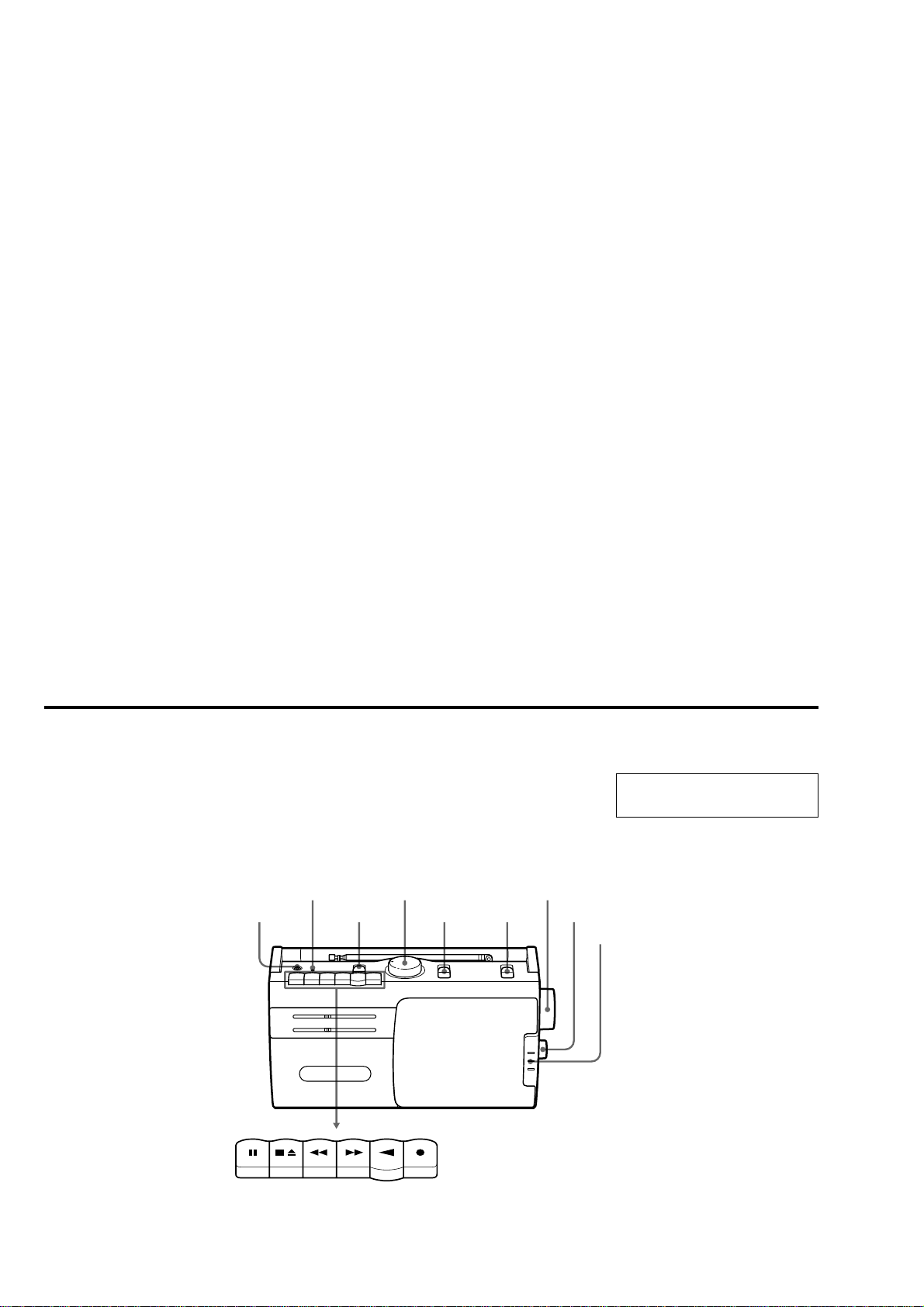
Location and Function of Controls
@
PAUSE
STOP/EJECT
SECTION 1
GENERAL
VOLUMEOPR/BATT
DPB
FF REW PLAY REC
BAND
This section is extracted from
instruction manual.
TUNING
FINE TUNINGFUNCTION
MIC
2
Page 3
SECTION 2
4
)
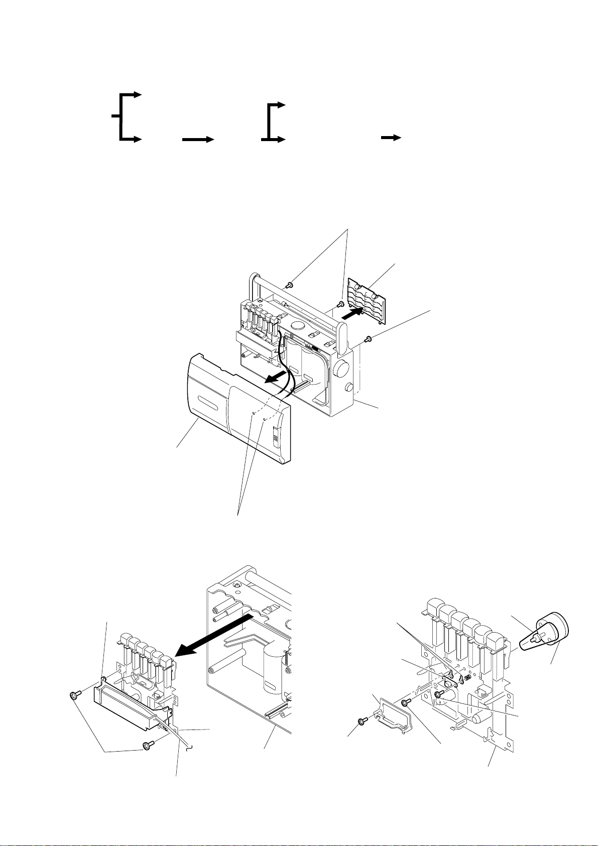
DISASSEMBLY
• The equipment can be removed using the following procedure.
Cabinet (front) ASSY
Record/playback head (HRP101),
Set
Reel/capstan motor (M101), Belt
CFM-S1
Cabi, rear
MD ASSY
Jack board, Main board,
Fine tune board
Note : Follow the disassembly procedure in the numerical order given.
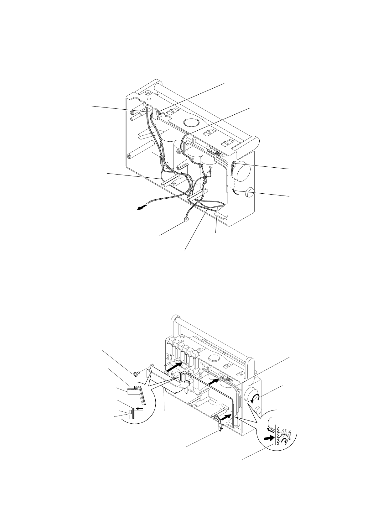
2-1. CABINET (FRONT) ASSY, “CABI, REAR”
2
Screws + BVTP 3X14
3
1
Battery terminal board, Power board
Lid, BATT
2
Screws + BVTP 3X1
Cabi, rear
2-2. MD ASSY
Chassis(B)
1
Screws
+ BVTP 3X10
Cabinet(front) ASSY
4
Remove solder (two places)
2
pointer
MD ASSY
Cabi, rear
2-3. RECORD/PLAYBACK HEAD (HRP101), REEL/CAPSTAN MOTOR (M101), BELT
8
5
Lug (T), plate
4
Record/playback
head (HRP101)
2
Guide, tape
1
Screws Tapping+B
6
Screws + P2X 5
MD ASSY
Belt
7
3
Reel/capstan
motor (M101
Screws
+ PTT 2X 5
3
Page 4
CFM-S1
r
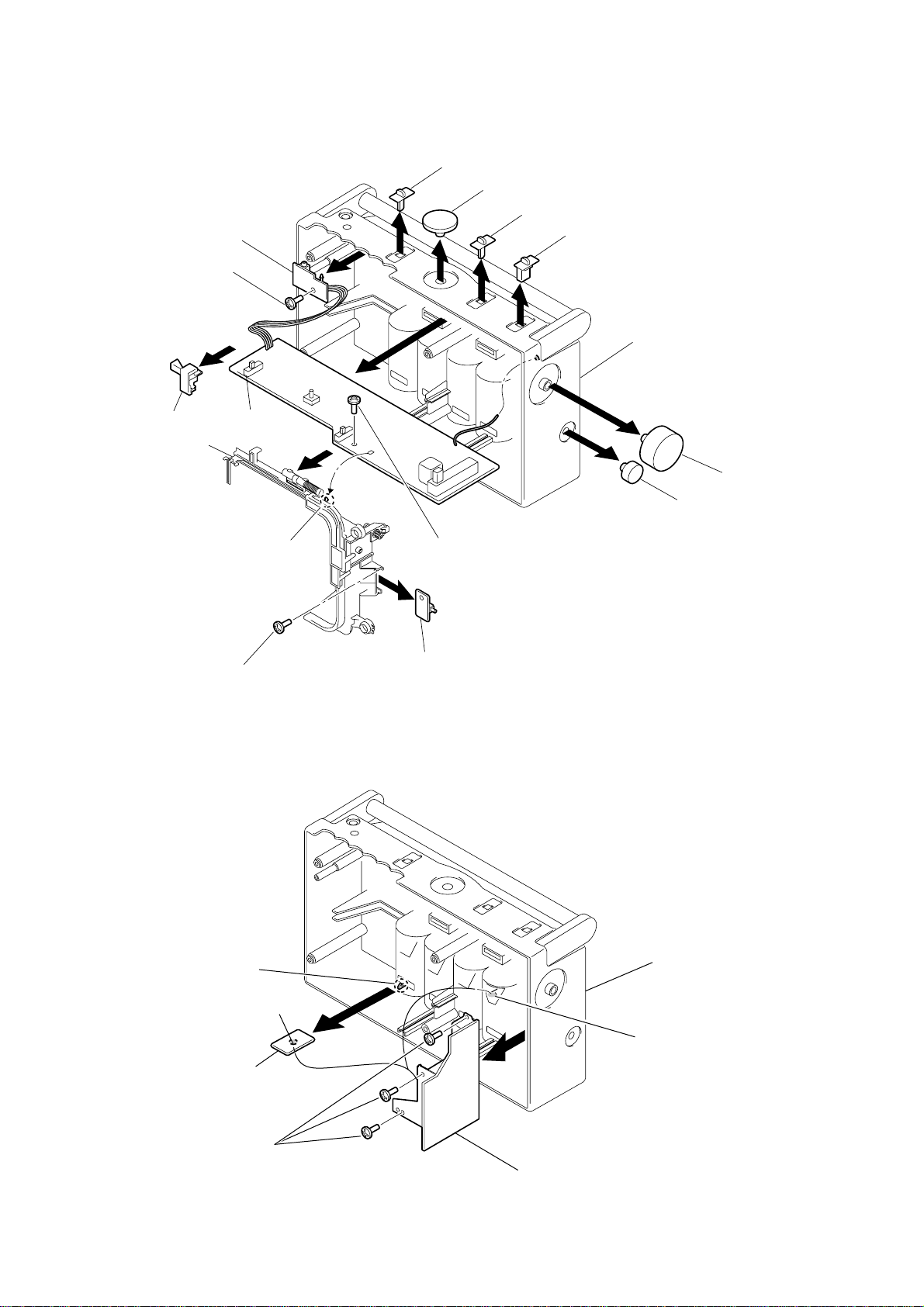
2-4. JACK BOARD, MAIN BOARD, FINE TUNE BOARD
Jack board
Knob(sound)
1
1
Knob(vol)
Knob(function)
1
Knob(band)
1
2
Screw +BVTP 3X10
Bracket(PWB)
Chassis(A)
7
3
Main board
5
Claw
Screws + BVTP 3X10
6
3
3
8
Fine tune board
2-5. BATTERY TERMINAL BOARD, POWER BOARD
4
Screw +BVTP 3X10
Cabi, rear
1
1
Knob(FT)
Knob(tune)
1
Claw
3
Remove solder
Battery terminal board
5
Screws + BVTP 3X10
2
6
Power board
Cabi, rear
4Remove Solde
4
Page 5
2-6. NOTE ON INSTALATION
)
Dress the lead wires as shown in figure.
CFM-S1
Main board (KH102)
To jack board
To battery terminal board
To speaker
(SP1)
2-7. DIAL POINTER SETTING
MIC (ECM101)
Power board (CN901)
Main board (KH101)
Main board (KH1)
Fine tune board (KH2
Power board (KH901)
4
2
Fit the pointer to the
chassis(B).
5
Set the left side of the
pointer to the convex
portion (a) on the
chassis(B).
Screw + BVTP 3X14
Pointer
Chassis(B)
Pointer
Chassis(B)
(a)
3
Chassis(B)
7
Bracket(P)
6
Pointer
6
Chassis(A)
1
Turn the knob(tune)
fully counterclockwise.
6 Hold the left side of pointer,
then insert the gear section
of pointer to groove of chassis(A).
5
Page 6
CFM-S1
)
SECTION 3
TEST MODE
3-1. MECHANICAL ADJUSTMENTS
PRECAUTION
1.Clean the following parts with a denatured-alcohol-moistened
swab :
record/playback head pinch roller
erase head rubber belts
capstan
2.Demagnetize the record/playback head with a head demagnetizer.
(Do not bring the head demagnetizer close to the erase head.)
3.Do not use a magnetized screwdriver for the adjustments.
4.After the adjustments, apply suitable locking compound to the
parts adjusted.
5. The adjustments should be performed with the rated power sup
ply voltage unless otherwise noted.
Torque Measurement
Torque Torque Meter Meter Reading
Forward CQ-102C
Forward
Back Tension
CQ-102C
Fast Forward CQ-201B
Rewind CQ-201B
Tape Tension Measurement
Torque Meter Meter Reading
CQ-403A
1.77 to 5.88 mN•m
(18 to 60 g•cm)
(0.25 to 0.83 oz•inch)
0.01 to 0.49 mN•m
(1 to 5 g•cm)
(0.014 to 0.069 oz•inch)
4.42 to 9.31 mN•m
(45 to 95 g•cm)
(0.63 to 1.31 oz•inch)
4.42 to 9.31 mN•m
(45 to 95 g•cm)
(0.63 to 1.31 oz•inch
more than 100g
(more than 3.53 oz)
)
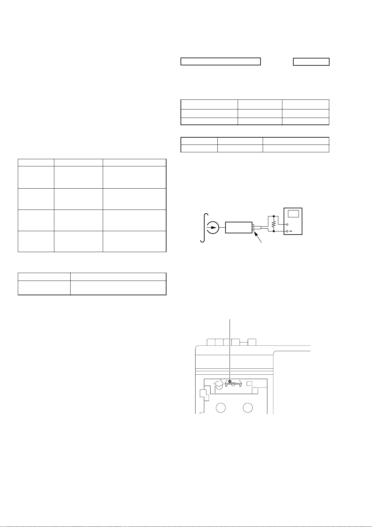
3-2. ELECTRICAL ADJUSTMENTS
TAPE RECORDER SECTION
FUNOTION switch : TAPE (RADIO OFF)
SOUND switch : OFF
VOLUME : MIN
Standard Output Level
Output terminal Earphone Speaker
load impedance 8Ω 6Ω
output signal level 0.25V (–10dB) 0.775V (0dB)
Test Tape
Type Signal Used for
WS-48A 3kHz, 0dB Tape Speed Adjustment
Record/Playback Head Azimuth Adjustment
Procedure :
1.Playback Mode
test tape
P-4-A100
(10kHz, -10dB)
set
8
Ω
J101 (Earphone jack
2.Rotate the screw to adjust level meter reading to the maximum.
Note : Adjust to the maximum peak though there may be two or
three peakes
3.After the adjustment, lock the adjustment screws with suitable
locking compound.
Adjustment Location :
0dB=0.775V
level meter
+
Head azimuth adjustent screw
6
Page 7
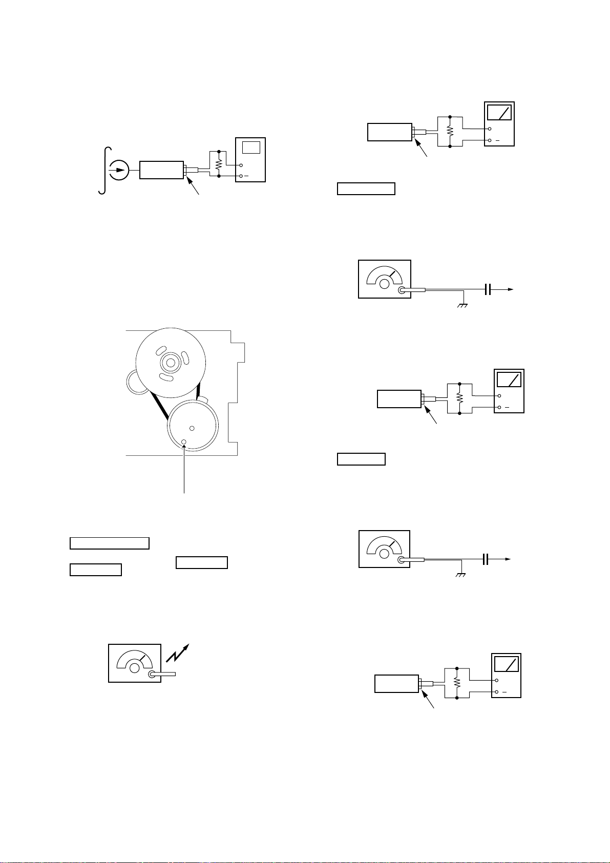
Tape Speed Adjustment
y
r
c
r
c
r
Procedure :
Mode : Playback
test tape
WS-48B
(3kHz, 0dB)
set
digital frequenc
counter
8Ω
+
J101 (Earphone jack)
level mete
8Ω
set
J101 (Earphone jack)
SW Section
BAND switch : SW1, SW2
FINE TUNING control : mechanical center
CFM-S1
+
Adjustment Value :3,000Hz
Standard Value :2,990 to 3,010Hz
Frequency difference between the beginning and the end of the tape
should be within 1.0% (30Hz).
Adjustment Location :
tape speed adjustment
control inside motor
AM RF signal
generator
30% amplitude
modulation by 400Hz signal
output level : as low as possible
set
FM Section
Function switch : FM
Volume : MIN
FM RF signal
generator
12pF
level mete
8Ω
+
J101 (Earphone jack)
telescopi
antenna
terminal
TUNER SECTION
MW Section
Function switch : MW
Volume : MIN
AM RF signal
generator
30% amplitude modulation by 400Hz
signal.
Output level : as low as possible
µ
0.01 F
0dB=1µV
22.5kHz frequency deviation by
400Hz signal.
Output level : as low as possible
Put the lead-wire
antenna close to
the set.
8Ω
set
J101 (Earphone jack)
telescopi
antenna
terminal
level mete
+
7
Page 8
CFM-S1
t
• Repeat the procedures in each adjustment several times, and the
frequency coverage and tracking adjustments should be finally
done by the trimmer capacitors.
< > : Saudi Arabia model
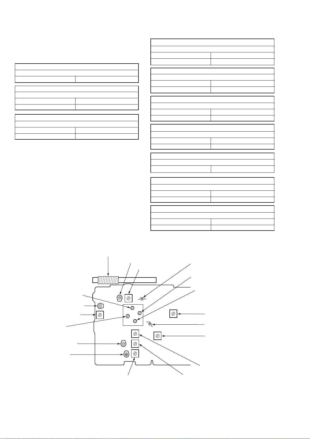
AM(MW/SW) IF ADJUSTMENT
Adjust for a maximum reading on level meter.
T1 455kHz
MW FREQUENCY COVERAGE ADJUSTMENT
Adjust for a maximum reading on level meter.
L4 520kHz <516kHz>
CT4 1,680kHz <1,630kHz>
MW TRACKING ADJUSTMENT
Adjust for a maximum reading on level meter.
L3 600kHz
CT3 1,400kHz
SW1 FREQUENCY COVERAGE ADJUSTMENT
Adjust for a maximum reading on level meter.
L7 2.2MHz
CT7 7.3MHz
SW1 TRACKING ADJUSTMENT
Adjust for a maximum reading on level meter.
L6 2.2MHz
CT6 7.3MHz
SW2 FREQUENCY COVERAGE ADJUSTMENT
Adjust for a maximum reading on level meter.
L9 6.8MHz
CT9 22.5MHz
SW2 TRACKING ADJUSTMENT
Adjust for a maximum reading on level meter.
L8 6.8MHz
CT8 22.5MHz
FM IF ADJUSTMENT
Adjust for a maximum reading on level meter.
L5 10.7MHz
FM FREQUENCY COVERAGE ADJUSTMENT
Adjust for a maximum reading on level meter.
L2 86.50MHz <87.35MHz>
CT2 109.50MHz <107.80MHz>
Adjustment Location : MAIN board (Component side)
L3: MW Tracking Adjustment
[MAIN BOARD]
(Component side)
CT3 : MW Tracking Adjustment
CT6 : SW1 Tracking Adjustment
L6 : SW1 Tracking Adjustment
CT4: MW Frequency
Coverage Adjustment
CT9 : SW2 Frequency
Coverage Adjustment
CT7 : SW1 Frequency
Coverage Adjustment
CT8 : SW2 Tracking Adjustment
L8 : SW2 Tracking Adjustment
L7 : SW1 Frequency
Coverage Adjustment
FM TRACKING ADJUSTMENT
Adjust for a maximum reading on level meter.
L1 86.50MHz <87.35MHz>
CT1 109.50MHz <107.80MHz>
L1 : FM Tracking Adjustment
CT1 : FM Tracking Adjustment
CT2 : FM Frequency
Coverage Adjustment
T1 : AM (MW/SW) IF Adjustmen
L2 : FM Frequency
Coverage Adjustment
L5 : FM IF Adjustment
L4 : MW Frequency
Coverage Adjustment
L9 : SW2 Frequency
Coverage Adjustment
8
Page 9

• Circuit Board Location.
d
CFM-S1
SECTION 4
DIAGRAMS
Jack board
Main board
Power board
Battery terminal board
Fine tune boar
9999
Page 10

CFM-S1
4-1. BLOCK DIAGRAMS
• Signal path.
F : FM
E : PB
a : REC
1010
Page 11

4-2. PRINTED WIRING BOARDS
CFM-S1
L3
MW
BAR
C6
L1
C3
CT1-1
CT1-2
JC18
L4
L9
L7
JC17
8
CV1-1
CV1-2
JC20
JC16
JC19
CV1-3
L8
CV1-4
CT7
JC15
C11
C24
C12
CT9
CT1-3
CT1-4
C9
CT8
EA
MODEL
C10
C21
C7
JC14
JC13
C23
C22
9 10
S1 1-8
BAND
SW1
SW2
JC1
D2
JC12
C8
JC11
JC9
C25
-4 -3
-6 -5
-8 -7
C31
JC8
JC10
JC2
-1-2
JC7
KH1
C20
Q1
JC5
JC6
CNP1
JC3
L6
JC4
B C E
D3
D4
R8
R9
1-680-390-
S1
FM
TELESCOPIC ANTENNA
MW
D1
CT6
C29
C28
11
(11)
ANT1
FM
z
Semiconductor
Location
Ref. No. Location
D1 B-9
D2 B-9
D3 C-9
D4 C-9
D101 C-6
D102 E-2
D103 C-6
D104 C-6
D140 D-5
D141 D-5
D901 F-4
D902 F-4
IC1 B-7
IC101 C-3
Q1 C-9
Q101 C-6
Q102 C-6
Q103 C-5
Q105 C-4
Q106 C-5
Q140 D-5
1
2
3 4 5 6 7
S101
Q101
B C E
C130
CF1
CF2
R4
R4
D101
j
T1
T1
R5
C19
C132
C18
JC24
JC23
JW3
C17
JW
C117
2
C14
IC1
C13
ANTENNA
C1
C2
JC21
JW1
C5
L2
C16
JC22
L5
R2
C15
JW
103
D104
FUNCTION
TAPE
(RADIO OFF)
RADIO
JW4
S101
JW111
-1 -2
D103
E
C
B
Q102
C131
R
R130
M901
A
S106
(TAPE POWR)
MAIN
BOARD
B
C
KH103
R116
REEL/CAPSTAN
CNP102
KH102
JW109
MOTOR
JW110
HRP101
REC/PB
M
SOUND
JW108
C119
C121
S103
OFF
ON
S103
-1 -2
HEAD
HE101
ERASE
HEAD
R
S102
(REC/PB)
R106
C112
C102
C104
R151
R150
JW106
C111
C148
C147
JW107
C110
JW113
R142
C141
C149
R149
R112
R111
C118
C120
30
25
20
C122
16
R108
C115
IC101
C101
R102
R109
R110
C109
C123
R114
R101
C105
C106
C113
R105
C108
C114
R103
C103
CNP101
1
R104
5
C107
10
R113
15
C116
RV101
VOLUME
Q105
E
C
B
R141
R140
C140
D140
ECM101
R107
R148
C142
R144
R143
R152
C150
D141
MIC
JW112
R147
C143
C146
Q106
R145
R153
E C B
R154
C145
R155
KH101
R146
Q103
Q140
JW
C144
JW104
105
R131
D
JACK
BOARD
R115
KH104
E
J101
v
R118
OPR/BATT
4
R117
1-680-391-
D102
1
SP1
SPEAKER
11
(11)
POWER
BOARD
F901
C903
F
CNP901
BATTERY
D902
C902
C901
D901
POWER TRANSFORMER
T901
J901
- AC IN
VOLTAGE
SELECTOR
220-240V
110-10V
S901
R
BOARD
C27
R6
TUNING
RV1
RV1
FINE
R7
KH2
C26
1-680-393-
11
(11)
TERMINAL BOARD
101
FINE TUNE
G
DRY BATTERY
SIZE "D"
(IEC DESIGNATION R20)
4PCS, 6V
JW
102
JW
1-680-392-
11
(11)
KH901
1-681-387-
H
11
(11)
Note:
• X : parts extracted from the component side.
• : Pattern on the side which is seen.
• f : internal component.
1111
Page 12

CFM-S1
4-3. SCHEMATIC DIAGRAM – MAIN SECTION (1/2) –
z
Refer to page 14 for Notes.
z
Refer to page 15 for IC Block Diagrams.
1212
Page 13

CFM-S1
4-4. SCHEMATIC DIAGRAM – MAIN SECTION (2/2) –
z
Refer to page 14 for Notes.
z
Refer to page 15 for IC Block Diagrams.
1313
Page 14

CFM-S1
Note on schematic Diagram: MAIN SECTION (1/2), (2/2)
• All capacitors are in µF unless otherwise noted. pF: µµF 50 WV or
less are not indicated except for electrolytics and tantalums.
• All resistors are in Ω and
• f : internal component.
Note: The components identified by mark 0 or dotted line with
mark 0 are critical for safety.
Replace only with part number specified.
• A : B+ Line.
• H : adjustment for repair.
• Power voltage is dc 6V and fed with regulated dc power supply
from external power voltage jack.
• Voltages are dc with respect to ground under no-signal (detuned)
conditions.
• Voltages are dc with respect to ground in playback mode.
no mark : FM
( ) : SW1, SW2, MW (RADIO SECTION), PLAY (TAPE
SECTION)
< > : MIC REC
[ ] : RADIO REC
• Voltages are taken with a VOM (Input impedance 10 MΩ).
Voltage variations may be noted due to normal production tolerances.
• Signal path.
F : FM
E : PB
a : REC
• Abbreviation
EA : Saudi Arabia
UAE : United Arab Emirates
1
/4 W or less unless otherwise specified.
14
14
Page 15

• IC BLOCK DIAGRAMS
IC1 TA2132AF
AM RF
AM RF
IN
IN
16
16
FM RF
FM RF
OUT
OUT
15
15
AM/FM
AM/FM
SW
SW
14
14
FM
FM
OSC
OSC
13
13
AM
AM
OSC
OSC
12
12
AFC
AFC
CFM-S1
DET
DET
OUT
OUT
QUAD
9
9
10
10
11
11
AM
RF
FM RF
1
2
FM RF
RF
GND
IN
IC101 MM1315BD
MIC-IN
B+
B+
+
–
FM/AM
FM
MIXAMMIX
3
MIX
OUT
AUX-IN
2930
B+
FM
OSC
AGC
AM
OSC
AGC
5
4
TAPE/AUX
28
VCC
REC/PLAY
27
B+
FM IF
MIX/ECMNCREC
25
26
B+
B+
FM
IF
6
IN
24
B+
AF
BUFF
AM
DET
AM
IF
7
AM IF
IN
POWER ON/OFF
+
–
+
–
FM
DET
GND
8
LPF
ALC DEL
2223
21
B+
B+
POP DEL
20
POWER GND
+
–
+
–
1819
PBTL2
17
P.VCC
P.VCC
16
1
MIC N.F
B+
B+
2
HEAD-IN(+)
B+
+
–
B+
3
HEAD-IN(–)
4
TAPE NF
5
6
TAPE EQ
VBIAS
7
BIAS
+
B+
–
+
–
+
12
POWER IN
–
13
RIPPLE
FILTER
14
POWER GND
15
BTL1
+
–
8
9
SIG-GND
SIG VCC
10
FILTER
RIPPLE
11
LIN-OUT
15
Page 16

CFM-S1
SECTION 5
EXPLODED VIEWS
NOTE :
• -XX, -X mean standardized parts, so they
may have some difference from the original
one.
• Items marked “ * ”are not stocked since they
are seldom required for routine service. Some
delay should be anticipated when ordering
these items.
• The mechanical parts with no reference
number in the exploded views are not
supplied.
5-1. FRONT CABINET SECTION
• Hardware (# mark) list and accessories and
packing materials are given in the last of this
parts list.
• Abbreviation
EA : Saudi Arabia
UAE : United Arab Emirates
3
4
The components identified by mark 0
or dotted line with mark 0 are critical
for safety.
Replace only with part number specified.
5
#1
#1
#1
SP1
#2
#2
6
#2
ECM101
1
2
Ref. No. Part No. Description Remark Ref. No. Part No. Description Remark
1 3-226-090-01 LID, CASSETTE
2 X-3380-354-1 CABINET FRONT SUB ASSY
3 3-226-062-01 SPRING (CAS)
4 3-922-112-31 DAMPER
5 3-226-056-01 LID, BATT
6 X-3380-400-1 WINDOW SUB ASSY(E,UAE)
6 X-3380-568-1 WINDOW SUB ASSY(EA)
ECM101 1-542-118-11 MICROPHONE, ELECTRET CONDENSER
SP1 1-529-973-11 SPEAKER
16
Page 17

5-2. REAR CABINET SECTION
8
CFM-S1
#2
53
55
56
81
51
57
58
#2
59
60
#2
79
61
#2
#2
80
52
54
84
82
L3
85
63
62
73
75
76
83
#4
77
64
#6
74
65
#2
#2
66
ANT1
#2
61
#5
67
6
69
70
71
72
#2
Ref. No. Part No. Description Remark Ref. No. Part No. Description Remark
51 3-226-046-01 POINTER
52 3-226-041-01 BRACKET (PWB)
* 53 3-226-040-01 CHASSIS (B)
* 54 1-680-392-11 BATTERY TERMINAL BOARD
55 3-226-052-01 BUTTON (PAUSE)
56 3-226-051-01 BUTTON (STOP)
57 3-226-050-01 BUTTON (FF)
58 3-226-049-01 BUTTON (REW)
59 3-226-048-01 BUTTON (PLAY)
60 X-3380-353-1 BUTTON (REC) SUB ASSY
61 3-226-057-01 ARM (L)
62 3-226-096-01 HANDLE (P)
63 3-226-094-01 KNOB (SOUND)
64 3-226-054-01 KNOB (VOL)
65 3-226-093-01 KNOB (FUNCTION)
66 3-226-092-01 KNOB (BAND)
67 3-226-065-01 TERMINAL, BATT (+-)
68 3-226-064-01 TERMINAL, BATT (-)
69 3-226-038-01 CABI, REAR (E,EA)
69 3-226-038-11 CABI, REAR (UAE)
70 3-226-055-01 KNOB (TUNE)
71 3-226-091-01 KNOB (FT)
* 72 1-681-387-11 POWER BOARD
73 3-226-060-01 TERMINAL, ANT
74 3-226-043-01 GEAR (VC)
* 75 A-3323-677-A MAIN BOARD, COMPLETE (EA)
* 75 A-3323-679-A MAIN BOARD, COMPLETE (E,UAE)
76 3-226-045-01 SHAFT (T)
77 3-226-063-01 SPRING (TUNE)
79 3-226-042-01 BRACKET (P)
80 3-226-044-01 GEAR (INTERVAL)
81 3-226-039-01 CHASSIS (A)
* 82 1-680-391-11 JACK BOARD
* 83 1-680-393-11 FINE TUNE BOARD
84 3-229-772-01 HOLDER (ANT)
85 3-229-784-01 CUSHION (V)
ANT1 1-501-820-11 ANTENNA, TELESCOPIC
L3 1-754-171-11 ANTENNA, FERRITEROD (MW) (MWTRACKING)
17
Page 18

CFM-S1
5-3. MECHANISM DECK SECTION-1
(MF-M20-117)
HE101
HRP101
#3
#3
122
121
105
103
108
104
107
102
119
106
101
118
110
112
124
120
111
117
123
109
113
114
115
116
Ref. No. Part No. Description Remark Ref. No. Part No. Description Remark
101 3-933-010-01 SPRING (S/P), TORSION
102 3-933-025-01 SPRING (P), TORSION
103 3-040-857-01 LEVER (P)
104 3-933-024-01 ROLLER, PINCH
105 3-933-019-01 SPRING (F/R), TORSION
106 3-933-028-01 SPRING (FWD), TORSION
107 3-933-016-01 GEAR (S REEL)
* 108 3-933-023-11 SLIDER (REC)
109 3-933-022-01 BASE, HEAD
* 110 3-933-017-11 SLIDER (REW)
* 111 3-933-018-11 SLIDER (FF)
* 112 3-933-009-11 SLIDER (STOP)
* 113 3-933-008-11 SLIDER (PAUSE)
114 3-933-004-01 CLAW, REEL
* 115 3-933-021-01 SLIDER (FRP)
* 116 3-933-006-01 SLIDER (EJECT)
117 3-934-833-01 SPRING (FRP)
118 3-022-794-02 SPRING (BT)
119 3-933-007-01 PLATE, LOCK
* 120 3-009-076-01 CHASSIS (HEAD)
121 3-010-625-01 GUIDE, TAPE
122 3-342-917-01 SCREW (IT3-C), TAPPING, + B
123 3-936-265-01 LUG (T), PLATE
124 4-936-201-01 SPRING, COMPRESSION
HE101 1-500-680-11 HEAD, MAGNETIC (ERASE)
HRP101 1-500-679-11 HEAD,MAGNETIC(RECORD/PLAYBACK)
18
Page 19

5-4. MECHANISM DECK SECTION-2
(MF-M20-117)
154
156
153
155
CFM-S1
157
158
159
168
160
167
S106
162
166
163
161
M101
152
164
#6
165
151
Ref. No. Part No. Description Remark Ref. No. Part No. Description Remark
151 3-933-029-01 LEVER, ERASING PREVENTION
152 3-933-182-01 SPRING, CASSETTE
153 3-932-995-01 GEAR (MID)
154 X-3371-667-1 CLUTCH ASSY
155 3-932-997-01 GEAR (CAM)
* 156 3-932-999-01 SLIDER (SW)
157 3-932-998-01 SPRING (GROUND), TORSION
158 3-009-648-01 LEVER (S.OFF)
159 3-009-650-02 SPRING (K), COMPRESSION
160 X-3373-572-1 REEL ASSY (N), T
161 3-933-020-11 BELT
162 X-3377-877-2 FLYWHEEL ASSY
163 3-932-993-01 CHASSIS, OUTSERT
164 3-343-358-01 RING, RETAINING
165 3-223-156-01 SPRING (CAM), COMPRESSION
166 3-934-336-01 BEARING
167 3-939-383-02 SPRING, COMPRESSION
168 3-936-438-01 LEVER (K)
M101 A-3052-373-A MOTOR ASSY (REEL/CAPSTAN) (INCLUDING
PULLEY)
S106 1-692-302-11 SWITCH, LEAF (TAPE POWER)
19
Page 20

CFM-S1
SECTION 6
BATTERY TERMINAL
ELECTRICAL PARTS LIST
JACKFINE TUNE MAIN
NOTE :
• Due to standardization, replacements in the
parts list may be different from the parts
specified in the diagrams or the components
used on the set.
• -XX, -X mean standardized parts, so they
may have some difference from the original
one.
• RESISTORS
All resistors are in ohms
METAL : Metal-film resistor
METAL OXIDE :Metal oxide-film resistor
F : nonflammable
• Items marked “ * ”are not stocked since
they are seldom required for routine service.
Some delay should be anticipated when
ordering these items.
Ref. No. Part No. Description Remark Ref. No. Part No. Description Remark
* 1-680-392-11 BATTERY TERMINAL BOARD
***********************
**********************************************************************
* 1-680-393-11 FINE TUNE BOARD
***************
<CAPACITOR>
C26 1-162-964-11 CERAMIC CHIP 0.001uF 10% 50V
C27 1-126-961-11 ELECT 2.2uF 20% 50V
<CABLE HOLDER>
* KH2 1-565-384-11 HOLDER, CABLE 3P
<RESISTOR>
R6 1-216-821-11 METAL CHIP 1K 5% 1/16W
R7 1-216-821-11 METAL CHIP 1K 5% 1/16W
<VARIABLE RESISTOR>
RV1 1-223-693-11 RES, VAR, CARBON 100K (FINE TUNING)
************************************************************
* 1-680-391-11 JACK BOARD
***********
<DIODE>
D102 8-719-059-97 LED L-34HD (OPR/BATT)
<JACK>
J101 1-563-330-11 JACK (@ )
<CABLE HOLDER>
* KH104 1-568-134-21 HOLDER, CABLE 6P
<RESISTOR>
R115 1-216-809-11 METAL CHIP 100 5% 1/16W
R117 1-216-819-11 METAL CHIP 680 5% 1/16W
R118 1-249-393-11 CARBON 10 5% 1/4W F
************************************************************
* A-3323-677-A MAIN BOARD, COMPLETE (EA)
* A-3323-679-A MAIN BOARD, COMPLETE (E,UAE)
******************************
• SEMICONDUCTORS
In each case, u : µ , for example :
uA.... : µ A.... , uPA.... : µ PA....
uPB.... : µ PB.... , uPC.... : µ PC....
uPD.... : µ PD....
• CAPACITORS
uF : µ F
• COILS
uH : µ H
• Abbreviation
EA : Saudi Arabia
UAE : United Arab Emirates
3-229-772-01 HOLDER (ANT)
3-229-784-01 CUSHION (V)
7-685-647-79 SCREW +BVTP3X10 TYPE2 N-S
C1 1-162-927-11 CERAMIC CHIP 100PF 5% 50V
C2 1-162-915-11 CERAMIC CHIP 10PF 0.5PF 50V
C3 1-162-915-11 CERAMIC CHIP 10PF 0.5PF 50V
C5 1-162-199-31 CERAMIC 10PF 5% 50V
C5 1-162-275-21 CERAMIC 22PF 5% 50V
C6 1-162-199-31 CERAMIC 10PF 5% 50V
C6 1-162-264-21 CERAMIC 5.6PF 5% 50V
C7 1-162-907-11 CERAMIC CHIP 2PF 0.25PF 50V
C8 1-162-966-11 CERAMIC CHIP 0.0022uF 10% 50V
C9 1-164-315-11 CERAMIC CHIP 470PF 5% 50V
C10 1-162-915-11 CERAMIC CHIP 10PF 0.5PF 50V
C11 1-162-192-31 CERAMIC 2.7PF 10% 50V
C12 1-162-199-31 CERAMIC 10PF 5% 50V
C13 1-162-970-11 CERAMIC CHIP 0.01uF 10% 25V
C14 1-162-970-11 CERAMIC CHIP 0.01uF 10% 25V
C15 1-165-176-11 CERAMIC CHIP 0.047uF 10% 16V
C16 1-162-919-11 CERAMIC CHIP 22PF 5% 50V
C17 1-162-970-11 CERAMIC CHIP 0.01uF 10% 25V
C18 1-126-963-11 ELECT 4.7uF 20% 50V
C19 1-104-665-11 ELECT 100uF 20% 10V
C20 1-164-230-11 CERAMIC CHIP 220PF 5% 50V
C21 1-164-315-11 CERAMIC CHIP 470PF 5% 50V
C22 1-162-964-11 CERAMIC CHIP 0.001uF 10% 50V
C23 1-162-198-31 CERAMIC 8.2PF 10% 50V
C24 1-162-968-11 CERAMIC CHIP 0.0047uF 10% 50V
C25 1-162-196-31 CERAMIC 5.6PF 10% 50V
C28 1-126-961-11 ELECT 2.2uF 20% 50V
C29 1-104-665-11 ELECT 100uF 20% 10V
C30 1-162-970-11 CERAMIC CHIP 0.01uF 10% 25V
C31 1-162-908-11 CERAMIC CHIP 3PF 0.25PF 50V
C32 1-164-315-11 CERAMIC CHIP 470PF 5% 50V
C101 1-162-966-11 CERAMIC CHIP 0.0022uF 10% 50V
C102 1-126-961-11 ELECT 2.2uF 20% 50V
The components identified by mark 0
or dotted line with mark 0 are critical
for safety.
Replace only with part number specified.
<CAPACITOR>
(E,UAE)
(EA)
(E,UAE)
(EA)
(E,UAE)
(EA)
20
Page 21

CFM-S1
MAIN
Ref. No. Part No. Description Remark Ref. No. Part No. Description Remark
C103 1-164-227-11 CERAMIC CHIP 0.022uF 10% 25V
C104 1-128-551-11 ELECT 22uF 20% 25V
CV3 1-151-693-11 CAP, VAR (TUNING)
CV4 1-151-693-11 CAP, VAR (TUNING)
C105 1-162-964-11 CERAMIC CHIP 0.001uF 10% 50V
C106 1-162-964-11 CERAMIC CHIP 0.001uF 10% 50V
C107 1-126-934-11 ELECT 220uF 20% 10V
C108 1-162-970-11 CERAMIC CHIP 0.01uF 10% 25V
C109 1-162-970-11 CERAMIC CHIP 0.01uF 10% 25V
C110 1-126-959-11 ELECT 0.47uF 20% 50V
C111 1-126-935-11 ELECT 470uF 20% 16V
C112 1-104-665-11 ELECT 100uF 20% 10V
C113 1-107-826-11 CERAMIC CHIP 0.1uF 10% 16V
C114 1-162-927-11 CERAMIC CHIP 100PF 5% 50V
C115 1-162-970-11 CERAMIC CHIP 0.01uF 10% 25V
C116 1-165-176-11 CERAMIC CHIP 0.047uF 10% 16V
C117 1-126-960-11 ELECT 1uF 20% 50V
C118 1-162-970-11 CERAMIC CHIP 0.01uF 10% 25V
C119 1-104-664-11 ELECT 47uF 20% 10V
C120 1-162-968-11 CERAMIC CHIP 0.0047uF 10% 50V
C121 1-126-768-11 ELECT 2200uF 20% 16V
C122 1-162-970-11 CERAMIC CHIP 0.01uF 10% 25V
C123 1-107-826-11 CERAMIC CHIP 0.1uF 10% 16V
C130 1-162-970-11 CERAMIC CHIP 0.01uF 10% 25V
C131 1-104-665-11 ELECT 100uF 20% 10V
C132 1-162-970-11 CERAMIC CHIP 0.01uF 10% 25V
C140 1-126-960-11 ELECT 1uF 20% 50V
C141 1-115-467-11 CERAMIC CHIP 0.22uF 10% 10V
C142 1-162-966-11 CERAMIC CHIP 0.0022uF 10% 50V
C143 1-107-826-11 CERAMIC CHIP 0.1uF 10% 16V
C144 1-126-960-11 ELECT 1uF 20% 50V
C145 1-162-927-11 CERAMIC CHIP 100PF 5% 50V
C146 1-126-960-11 ELECT 1uF 20% 50V
C147 1-126-963-11 ELECT 4.7uF 20% 50V
C148 1-107-826-11 CERAMIC CHIP 0.1uF 10% 16V
C149 1-126-961-11 ELECT 2.2uF 20% 50V
C150 1-126-963-11 ELECT 4.7uF 20% 50V
<FILTER>
CF1 1-795-079-71 FILTER, CERAMIC
CF2 1-781-790-11 FILTER, AM CERAMIC
<CONNECTOR>
* CNP1 1-785-654-11 PIN, CONNECTOR (PC BOARD) 2P
* CNP101 1-785-669-11 PIN, CONNECTOR (PC BOARD) 3P
* CNP102 1-785-670-11 PIN, CONNECTOR (PC BOARD) 4P
<DIODE>
D1 8-719-991-33 DIODE 1SS133T-77
D2 8-719-991-33 DIODE 1SS133T-77
D3 8-719-991-33 DIODE 1SS133T-77
D4 8-719-991-33 DIODE 1SS133T-77
D101 8-719-982-11 DIODE MTZJ-4.3B
D103 8-719-991-33 DIODE 1SS133T-77
D104 8-719-991-33 DIODE 1SS133T-77
D140 8-719-991-33 DIODE 1SS133T-77
D141 8-719-991-33 DIODE 1SS133T-77
<IC>
IC1 8-759-697-57 IC TA2132AF(EL)
IC101 8-759-467-54 IC MM1315BD
<JUMPER RESISTOR>
JC1 1-216-864-91 SHORT 0
JC2 1-216-864-91 SHORT 0
JC3 1-216-864-91 SHORT 0
JC4 1-216-864-91 SHORT 0
JC5 1-216-864-91 SHORT 0
JC6 1-216-864-91 SHORT 0
JC7 1-216-864-91 SHORT 0
JC8 1-216-864-91 SHORT 0
JC9 1-216-864-91 SHORT 0
JC10 1-216-864-91 SHORT 0
JC11 1-216-864-91 SHORT 0
JC12 1-216-864-91 SHORT 0
JC13 1-216-864-91 SHORT 0
JC14 1-216-864-91 SHORT 0
JC15 1-216-864-91 SHORT 0
JC16 1-216-864-91 SHORT 0
JC17 1-216-864-91 SHORT 0
JC18 1-216-864-91 SHORT 0
JC19 1-216-864-91 SHORT 0
JC20 1-216-864-91 SHORT 0
JC21 1-216-864-91 SHORT 0
JC22 1-216-864-91 SHORT 0
JC23 1-216-864-91 SHORT 0
JC24 1-216-864-91 SHORT 0
<CABLE HOLDER>
<TRIMMER CAPACITOR>
CT1 1-151-693-11 CAP, VAR (FM TRACKING)
CT2 1-151-693-11 CAP, VAR (FM FREQUENCY COVERAGE)
CT3 1-151-693-11 CAP, VAR (MW TRACKING)
CT4 1-151-693-11 CAP, VAR (MW FREQUENCY COVERAGE)
CT6 1-141-360-41 CAP, FILM TRIMMER 5PF (SW1 TRACKING)
CT7 1-141-360-41 CAP, FILM TRIMMER 5PF(SW1 FREQUENCY
COVERAGE)
CT8 1-141-360-41 CAP, FILM TRIMMER 5PF (SW2 TRACKING)
CT9 1-141-360-41 CAP, FILM TRIMMER 5PF (SW2 FREQUENCY
COVERAGE)
CV1 1-151-693-11 CAP, VAR (TUNING)
CV2 1-151-693-11 CAP, VAR (TUNING)
* KH1 1-565-384-11 HOLDER, CABLE 3P
* KH101 1-573-287-11 HOLDER, CABLE 2P
* KH102 1-573-287-11 HOLDER, CABLE 2P
* KH103 1-565-385-11 HOLDER, CABLE 4P
<COIL>
L1 1-424-793-11 COIL, AIR-CORE (FM TRACKING)
L2 1-424-726-11 COIL, AIR-CORE (E,UAE) (FM FREQUENCY
COVERAGE)
L2 1-419-998-11 COIL, OSCILLATION (EA) (FM FREQUENCY
COVERAGE)
L3 1-754-171-11 ANTENNA, FERRITEROD (MW) (MW TRACKING)
21
Page 22

CFM-S1
POWERMAIN
Ref. No. Part No. Description Remark Ref. No. Part No. Description Remark
L4 1-406-040-00 COIL (OSC) (MW FREQUENCY COVERAGE)
<VARIABLE RESISTOR>
L5 1-409-944-11 COIL (DET) (FM IF)
L6 1-402-597-31 COIL (ANT) (SW1 TRACKING)
L7 1-419-999-11 COIL, OSCILLATION (SW1 FREQUENCY
COVERAGE)
L8 1-416-843-11 COIL (ANT) (SW2 TRACKING)
L9 1-416-843-11 COIL (ANT) (SW2 FREQUENCY COVERAGE)
L10 1-412-975-41 INDUCTOR, CHIP 0.47uH
<TRANSISTOR>
Q1 8-729-036-89 TRANSISTOR KTC3198GR-A
Q101 8-729-036-90 TRANSISTOR KTC3198BL-AT
Q102 8-729-026-39 TRANSISTOR 2SA933AS-QT
Q103 8-729-036-89 TRANSISTOR KTC3198GR-A
Q105 8-729-120-28 TRANSISTOR 2SC1623-L5L6
Q106 8-729-120-28 TRANSISTOR 2SC1623-L5L6
Q140 8-729-120-28 TRANSISTOR 2SC1623-L5L6
<RESISTOR>
R2 1-216-831-11 METAL CHIP 6.8K 5% 1/16W
R5 1-216-815-11 METAL CHIP 330 5% 1/16W
R8 1-216-845-11 METAL CHIP 100K 5% 1/16W
R9 1-216-833-11 METAL CHIP 10K 5% 1/16W
R101 1-216-835-11 METAL CHIP 15K 5% 1/16W
R102 1-216-837-11 METAL CHIP 22K 5% 1/16W
R103 1-216-813-11 METAL CHIP 220 5% 1/16W
R104 1-216-813-11 METAL CHIP 220 5% 1/16W
R105 1-216-797-11 METAL CHIP 10 5% 1/16W
R106 1-249-417-11 CARBON 1K 5% 1/4W F
RV101 1-227-401-11 RES, VAR, CARBON 20K (VOLUME)
<SWITCH>
S1 1-786-059-11 SWITCH, SLIDE (BAND)
S101 1-572-624-11 SWITCH, SLIDE (FUNCTION)
S102 1-786-130-11 SWITCH, PUSH (1 KEY) (PB/REC)
S103 1-572-624-11 SWITCH, SLIDE (SOUND)
<TRANSFORMER>
T1 1-419-997-11 COIL, IF (AM IF)
************************************************************
* 1-681-387-11 POWER BOARD
*************
1-533-233- HOLDER, FUSE
<CAPACITOR>
C901 1-161-494-00 CERAMIC 0.022uF 25V
C902 1-161-494-00 CERAMIC 0.022uF 25V
C903 1-126-768-11 ELECT 2200uF 20% 16V
<CONNECTOR>
* CNP901 1-785-668-11 PIN, CONNECTOR (PC BOARD) 2P
<DIODE>
D901 8-719-063-79 DIODE 1N4002B
D902 8-719-063-79 DIODE 1N4002B
R107 1-216-825-11 METAL CHIP 2.2K 5% 1/16W
R108 1-249-417-11 CARBON 1K 5% 1/4W F
R109 1-216-837-11 METAL CHIP 22K 5% 1/16W
R110 1-216-835-11 METAL CHIP 15K 5% 1/16W
R111 1-249-417-11 CARBON 1K 5% 1/4W F
R112 1-216-853-11 METAL CHIP 470K 5% 1/16W
R113 1-249-407-11 CARBON 150 5% 1/4W F
R114 1-216-797-11 METAL CHIP 10 5% 1/16W
R116 1-216-821-11 METAL CHIP 1K 5% 1/16W
R119 1-249-417-11 CARBON 1K 5% 1/4W F
R130 1-216-811-11 METAL CHIP 150 5% 1/16W
R131 1-216-829-11 METAL CHIP 4.7K 5% 1/16W
R140 1-216-831-11 METAL CHIP 6.8K 5% 1/16W
R141 1-216-825-11 METAL CHIP 2.2K 5% 1/16W
R142 1-216-841-11 METAL CHIP 47K 5% 1/16W
R143 1-216-841-11 METAL CHIP 47K 5% 1/16W
R144 1-216-845-11 METAL CHIP 100K 5% 1/16W
R145 1-216-841-11 METAL CHIP 47K 5% 1/16W
R146 1-216-855-11 METAL CHIP 680K 5% 1/16W
R147 1-216-829-11 METAL CHIP 4.7K 5% 1/16W
R148 1-249-409-11 CARBON 220 5% 1/4W F
R149 1-216-827-11 METAL CHIP 3.3K 5% 1/16W
R150 1-216-827-11 METAL CHIP 3.3K 5% 1/16W
R151 1-216-825-11 METAL CHIP 2.2K 5% 1/16W
R152 1-216-855-11 METAL CHIP 680K 5% 1/16W
R153 1-216-821-11 METAL CHIP 1K 5% 1/16W
R154 1-249-417-11 CARBON 1K 5% 1/4W F
R155 1-249-417-11 CARBON 1K 5% 1/4W F
<FUSE>
0 F901 1-532-234-11 FUSE (T80mA 250V)
<JACK>
0 J901 1-526-838-11 INLET, AC 2P ( - AC IN)
<CABLE HOLDER>
* KH901 1-573-287-11 HOLDER, CABLE 2P
<SWITCH>
0 S901 1-572-290-11 SWITCH, POWER (VOLTAGE CANGE)
(VOLTAGE SELECTOR)
<TRANSFORMER>
0 T901 1-435-877-11 TRANSFORMER, POWER
***********************************************************
MISCELLANEOUS
**************
ANT1 1-501-820-11 ANTENNA, TELESCOPIC
ECM101 1-542-118-11 MICROPHONE, ELECTRET CONDENSER
HE101 1-500-680-11 HEAD, MAGNETIC (ERASE)
HRP101 1-500-679-11 HEAD,MAGNETIC(RECORD/PLAYBACK)
M101 A-3052-373-A MOTOR ASSY (CAPSTAN/REEL) (INCLUDING
PULLEY)
S106 1-692-302-11 SWITCH, LEAF (TAPE POWER)
SP1 1-529-973-11 SPEAKER
************************************************************
22
The components identified by mark 0
or dotted line with mark 0 are critical
for safety.
Replace only with part number specified.
Page 23

Ref. No. Part No. Description Remark
ACCESORIES & PACKING MATERIALS
*******************************
0 1-569-008-21 ADAPTOR, CONVERSION (2P) (EA)
0 1-769-412-11 CORD, POWER
3-228-216-11 MANUAL, INSTRUCTION
(ENGLISH, FRENCH, SPANISH, ARABIC)
************************************************************
*********************
HARDWARE LIST
*********************
#1 7-685-649-79 SCREW +BVTP 3X14 TYPE2 N-S
#2 7-685-647-79 SCREW +BVTP 3X10 TYPE2 N-S
#3 7-685-782-01 SCREW +PTT 2X5 (S)
#4 7-685-247-19 SCREW +KTP 3X10 TYPE2 NON-SLIT
#5 7-682-148-13 SCREW +P 3X8
#6 7-621-770-87 SCREW +P 2.6X5
The components identified by mark 0
or dotted line with mark 0 are critical
for safety.
Replace only with part number specified.
CFM-S1
23
Page 24

CFM-S1
REVISION HISTORY
Clicking the version allows you to jump to the revised page.
Also, clicking the version at the upper right on the revised page allows you to jump to the next revised
page.
Ver. Date Description of Revision
1.0 2001.02 New
 Loading...