

Sony CFM-20-L Service manual
CFM-20L
SERVICE MANUAL
Ver 1.0 2001.04
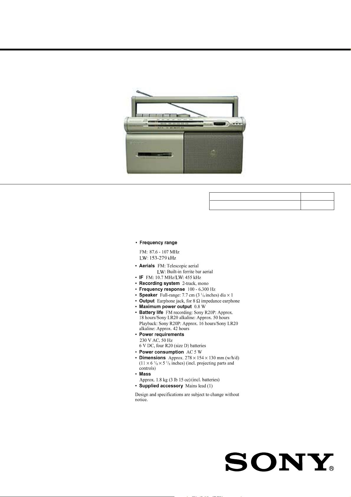
SPECIFICATIONS
AEP Model
Model Name Using Similar Machanism CFM-20
Tape Transport Mechanism Type MF-M20-117
9-873-114-11
2001D0200-1
© 2001.4
RADIO CASSETTE-CORDER
Sony Corporation
Personal Audio Company
Shinagawa Tec Service Manual Production Group
CFM-20L
TABLE OF CONTENTS
Specifications ........................................................................... 1
1. GENERAL
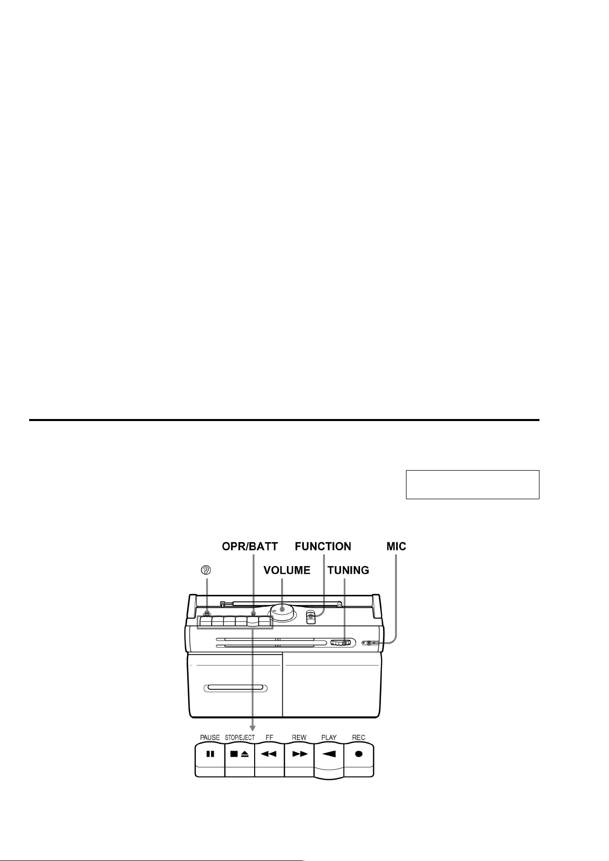
Location and Function of Controls .................................... 2
2. DISASSEMBLY
2-1. Cabinet (Front) Sub ASSY, Cabinet (Rear) ASSY .... 3
2-2. MD ASSY................................................................... 3
2-3. Record/Playback Head (HRP101),
Reel/Capstan Motor (M101),Belt ............................... 4
2-4. Jack Board, Main Board ............................................. 4
2-5. Batt (+) Board, Power Board ...................................... 5
3. ADJUSTMENTS
3-1. Mechanical Adjustments............................................. 6
3-2. Electrical Adjustments ................................................ 6
SAFETY-RELATED COMPONENT WARNING!!
COMPONENTS IDENTIFIED BY MARK ! OR DOTTED LINE WITH
MARK !ON THE SCHEMATIC DIAGRAMS AND IN THE PARTS LIST
ARE CRITICAL TO SAFE OPERATION.
REPLACE THESE COMPONENTS WITH SONY PARTS WHOSE
PART NUMBERS APPEAR AS SHOWN IN THIS MANUAL OR IN
SUPPLEMENTS PUBLISHED BY SONY.
4. DIAGRAMS
4-1. Block Diagrams .......................................................... 9
4-2. Printed Wiring Boards .............................................. 10
4-3. Schematic Diagrams -Main Section (1/2) - .............. 11
4-4. Schematic Diagrams -Main Section (2/2) - ............. 12
5. EXPLODED VIEWS
5-1. Front Cabinet Section ............................................... 15
5-2. Rear Cabinet Section ................................................ 16
5-3. Mechanism Deck Section-1(MF-M20-117) ............. 17
5-4. Mechanism Deck Section-2(MF-M20-117) ............. 18
6. ELECTRICAL PARTS LIST ........................................ 19
Notes on chip component replacement
• Never reuse a disconnected chip component.
• Notice than the minus side of a tantalum capactior may be
damaged by heat.
Location and Function of Controls
SECTION 1
GENERAL
This section is extracted from
instruction manual.
2
SECTION 2
)
Y
DISASSEMBLY
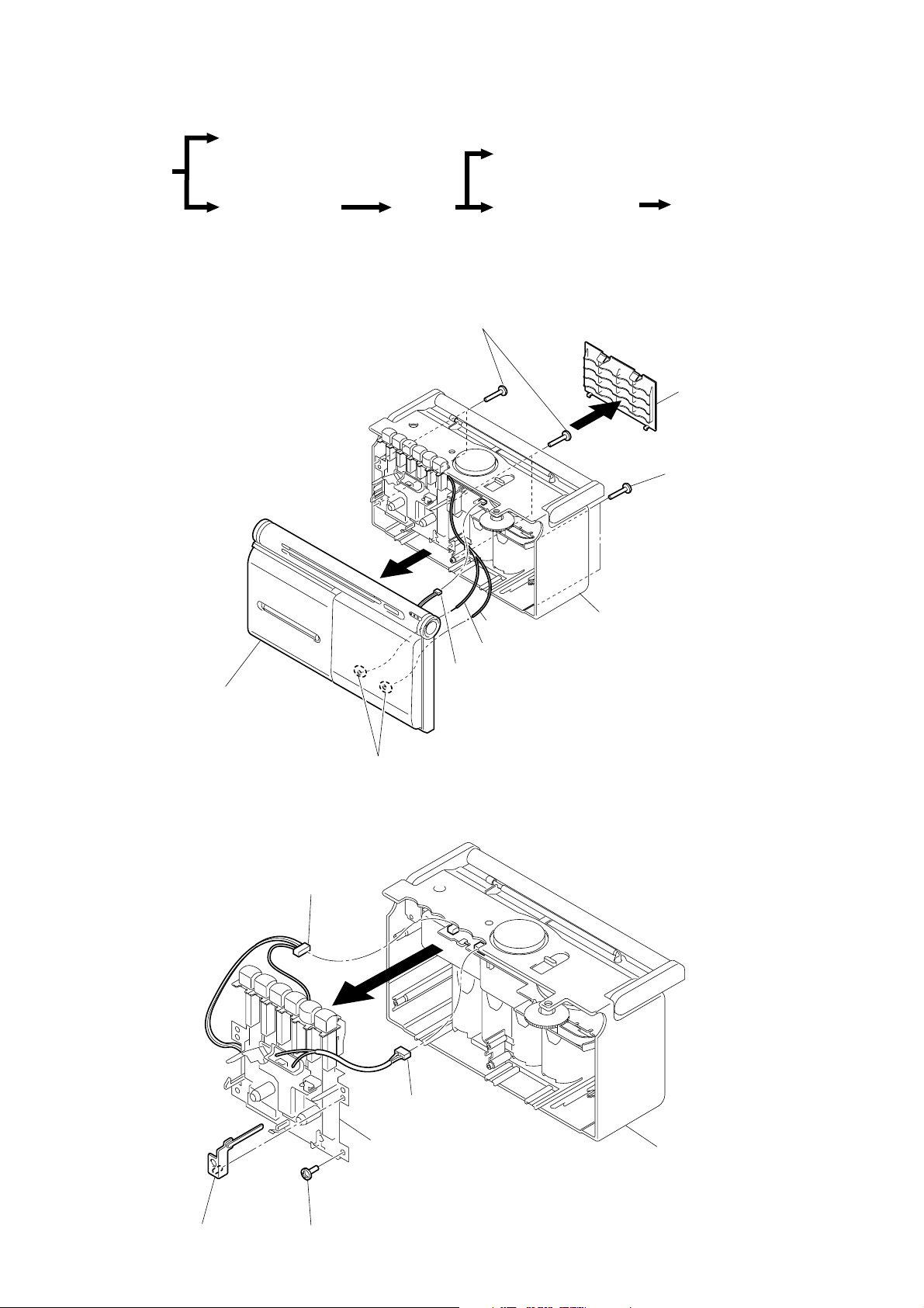
• The equipment can be removed using the following procedure.
Cabinet (front) sub ASSY
Set
CFM-20L
Record/playback head (HRP101),
Reel/capstan motor (M101), Belt
Cabinet (rear) ASSY
MD ASSY
Jack board, Main board
Note : Follow the disassembly procedure in the numerical order given.
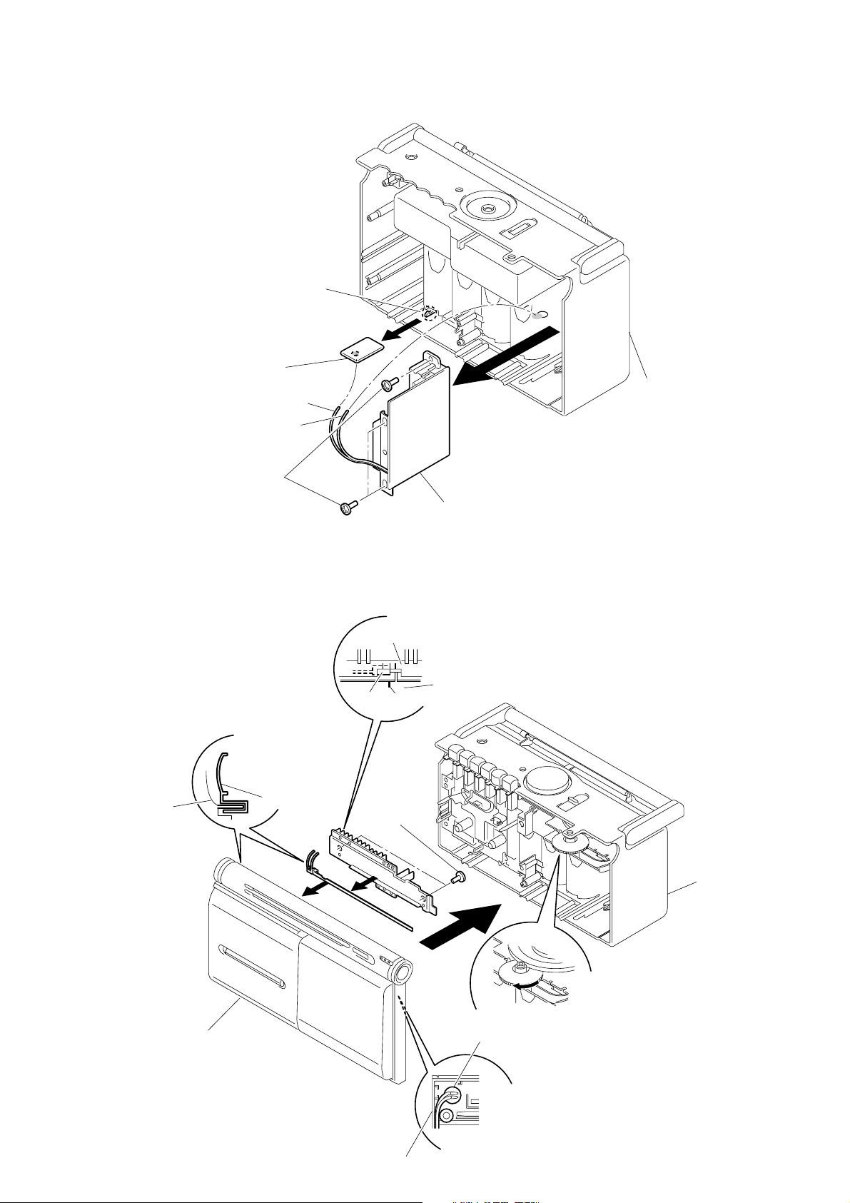
2-1. CABINET (FRONT) SUB ASSY, CABINET (REAR) ASSY
2
Screws (+ BVTP 3X14)
3
White
White/red
5
CNP103
6
Cabinet (front) sub ASSY
Batt(+) board, Power board
Lid, BATT
1
2
Screws
(+ BVTP 3X14
Cabinet (rear) ASSY
2-2. MD ASSY
Bracket (VOL)
4
Remove solder (two place)
3
CNP102
4
5
MD ASSY
1
Screw (+ BVTP 3X10)
2
CNP101
Cabinet (rear) ASS
3
CFM-20L
Y
)
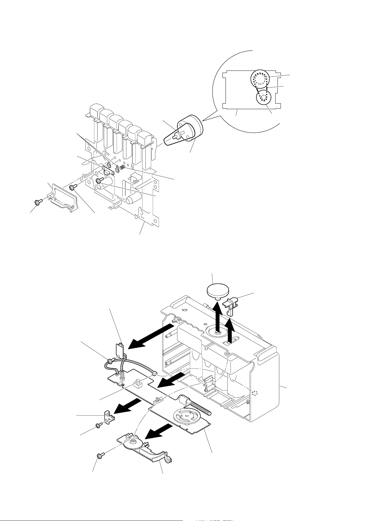
2-3. RECORD/PLAYBACK HEAD (HRP101), REEL/CAPSTAN MOTOR (M101), BELT
• Attaching belt
Flywheel ASS
Belt
5
Lug (T), plate
4
Record/playback
head (HRP101)
2
Guide, tape
1
Screws Tapping+B
(+PTT 2X5(s))
7
Screw + P2.6X 5
2-4. JACK BOARD , MAIN BOARD
MD ASSY
9
Belt
3
Screws
+ PTT 2X 5
8
Reel/capstan
motor (M101)
6
Spring, Compr
Knob (VOL)
MD ASSY
M101
Knob (FUN)
Bracket (PWB)
Screw
5
(+ BVTP 3X10)
7
Screw
(+ BVTP 3X10)
9
CNP901
3
Jack board
6
Screw
(+ BVTP 3X10)
8
4
Chassis
0
1
2
Cabinet (rear
Main board
4
2-5. BATT (+) BOARD, POWER BOARD
)
1
2
5
7
Cabinet (front)
Pointer
Cabinet (front)
Cabinet (front)
Scrached line
ECM101
Set the leads from microphone(ECM101)
as shown in the figure.
Set Pointer to "Cabinet
(front)" as shown in the
figure.
4
Set the right side edge
of Pointer to the scratched line
on
Cabinet (front)
.
3
Screws
6
Turn knob (tune) fully in the
direction of the arrow as shown
in the figure.
Cabinet (rear) ASSY
Cabinet (front)
(+BVTP 3X10)
Pointer
Back plate
1
Claw
Batt (+) board
Red
White
2
4
CFM-20L
Cabinet (rear
3
Screws
(+ BVTP 3X10)
Power board
• DIAL POINTER SETTING
Note : Follow the installation procedure in the numerical order given.
5
CFM-20L
)
SECTION 3
ADJUSTMENTS
3-1. MECHANICAL ADJUSTMENTS
PRECAUTION
1.Clean the following parts with a denatured-alcohol-moistened
swab :
record/playback head pinch roller
erase head rubber belts
capstan
2.Demagnetize the record/playback head with a head demagnetizer.
(Do not bring the head demagnetizer close to the erase head.)
3.Do not use a magnetized screwdriver for the adjustments.
4.After the adjustments, apply suitable locking compound to the
parts adjusted.
5. The adjustments should be performed with the rated power
supply voltage unless otherwise noted.
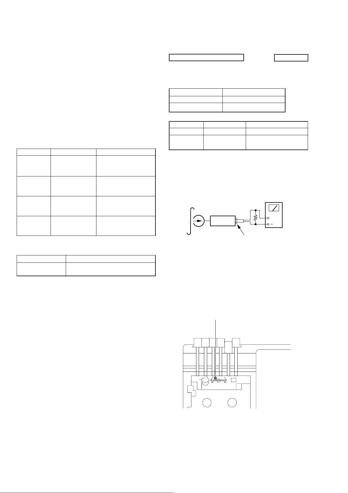
Torque Measurement
Torque Torque Meter Meter Reading
Forward CQ-102AS
Forward
Back Tension
CQ-102AS
Fast Forward CQ-201WS
Rewind CQ-201WS
1.77 to 5.88 mN•m
(18 to 60 g•cm)
(0.25 to 0.83 oz•inch)
0.01 to 0.49 mN•m
(1 to 5 g•cm)
(0.014 to 0.069 oz•inch)
4.42 to 9.31 mN•m
(45 to 95 g•cm)
(0.63 to 1.31 oz•inch)
4.42 to 9.31 mN•m
(45 to 95 g•cm)
(0.63 to 1.31 oz•inch
)
3-2. ELECTRICAL ADJUSTMENTS
TAPE RECORDER SECTION
FUNOTION switch (S101) : TAPE (RADIO OFF)
VOLUME (RV101) : MIN
Standard Output Level
Output terminal Earphone jack (J101)
load impedance 8Ω
output signal level 0.25V (–10dB)
Test Tape
Type Signal Used for
WS-48A 3kHz, 0dB Tape Speed Adjustment
P-4-A063 6.3kHz
Record/Playback Head
Azimuth Adjustment
Record/Playback Head Azimuth Adjustment
Procedure :
1.Playback Mode
test tape
P-4-A063J
(6.3kHz, -10dB)
set
Ω
8
J101 (Earphone jack
0dB=0.775V
level meter
+
Tape Tension Measurement
Torque Meter Meter Reading
CQ-405AS
more than 60g
(more than 2.12 oz)
2.Rotate the screw to adjust level meter reading to the maximum.
Note : Adjust to the maximum peak though there may be two or
three peakes
3.After the adjustment, lock the adjustment screws with suitable
locking compound.
Adjustment Location :
Head azimuth adjustment screw
6
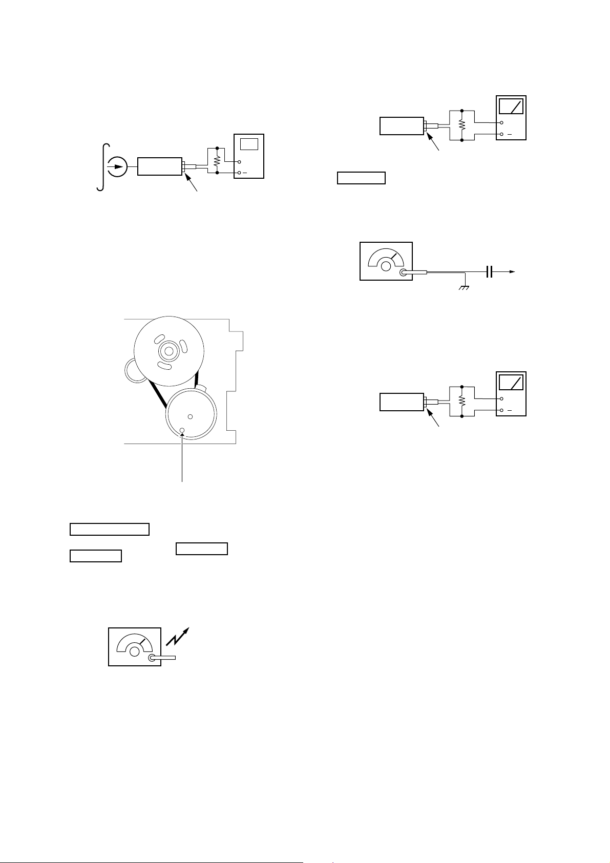
Tape Speed Adjustment
r
r
c
Procedure :
Mode : Playback
test tape
WS-48B
(3kHz, 0dB)
set
digital frequency
counter
8Ω
+
J101 (Earphone jack)
set
FM Section
Function switch (S101) : FM
Volume : MIN
CFM-20L
level mete
8Ω
+
J101 (Earphone jack)
Adjustment Value :3,000Hz
Standard Value :2,960 to 3,040Hz
Frequency difference between the beginning and the end of the tape
should be within 1.0% (30Hz).
Adjustment Location :
tape speed adjustment
control inside motor
FM RF signal
generator
75kHz frequency deviation by
1kHz signal.
Output level : as low as possible
8Ω
set
J101 (Earphone jack)
µ
0.01 F
telescopi
antenna
terminal
level mete
+
TUNER SECTION
LW Section
0dB=1µV
Function switch (S101) : LW
Volume : MIN
CT3, CT4 : mechanical center
AM RF signal
generator
30% amplitude modulation by 400Hz
signal.
Output level : as low as possible
Put the lead-wire
antenna close to
the set.
7
 Loading...