

Sony CFD-W57 Service Manual
SERVICE MANUAL
Ver 1.1 1999. 10
SUPPLEMENT-1
File this supplement with the service manual.
Subject : Change of Boards
Printed wiring board and schematic diagram of new type, and changed parts list
are described in this Supplement-1.
Refer to original service manual (9-923-399-11) previously issued for the other
information.
When performing service and inspection, check the suffix of the part number of
boards.
CFD-W57
US Model
E Model
(ECN-RCA00409)
Refer to the service manual for a board with a suffix number of -14 when reparing
a board with a suffix number of -12 or -13 for the following boards:
TUNER, MAIN, LAMP , RECORD/PLAYBACK SWITCH, HEADPHONE and
POWER boards.
– 1 –
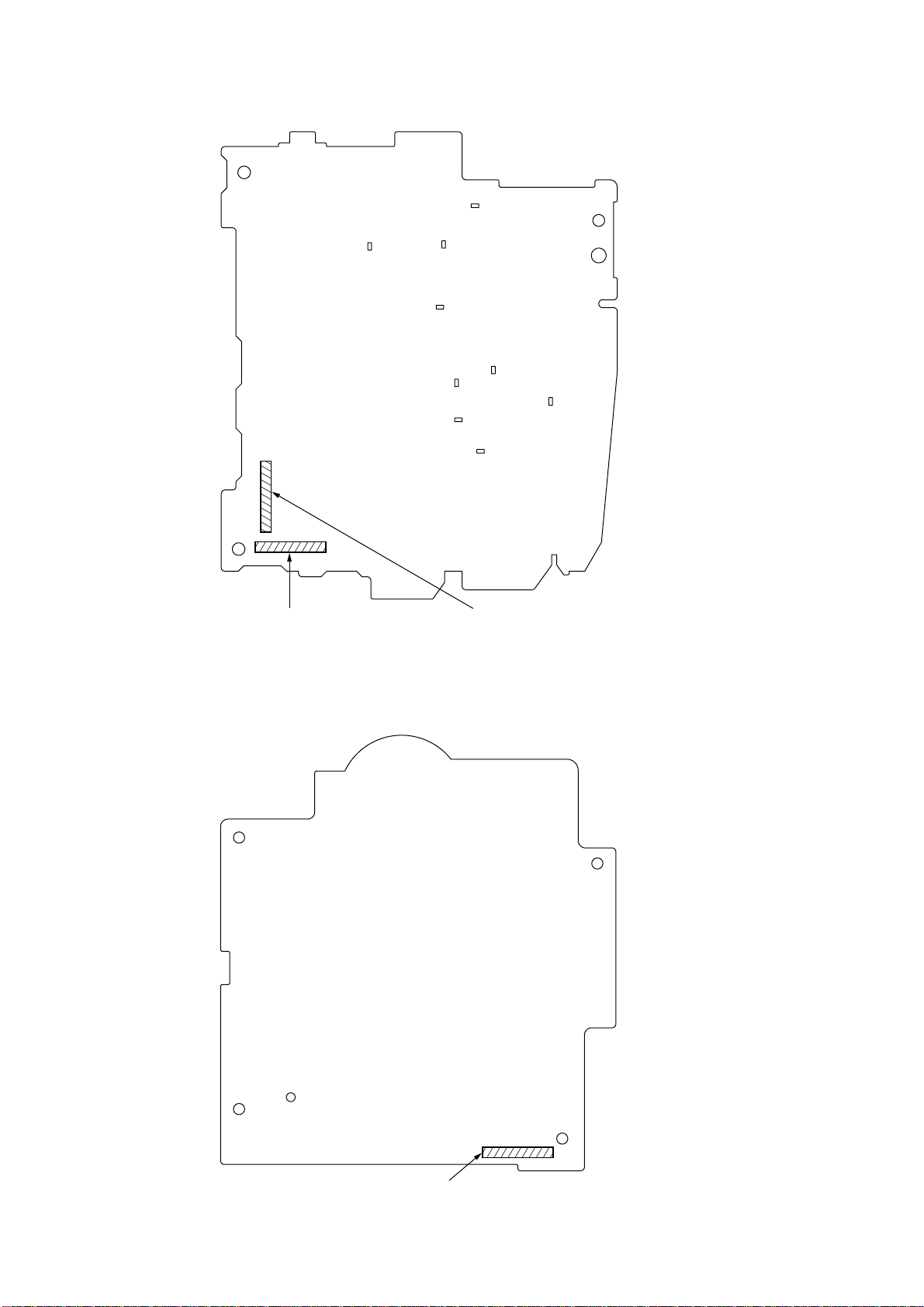
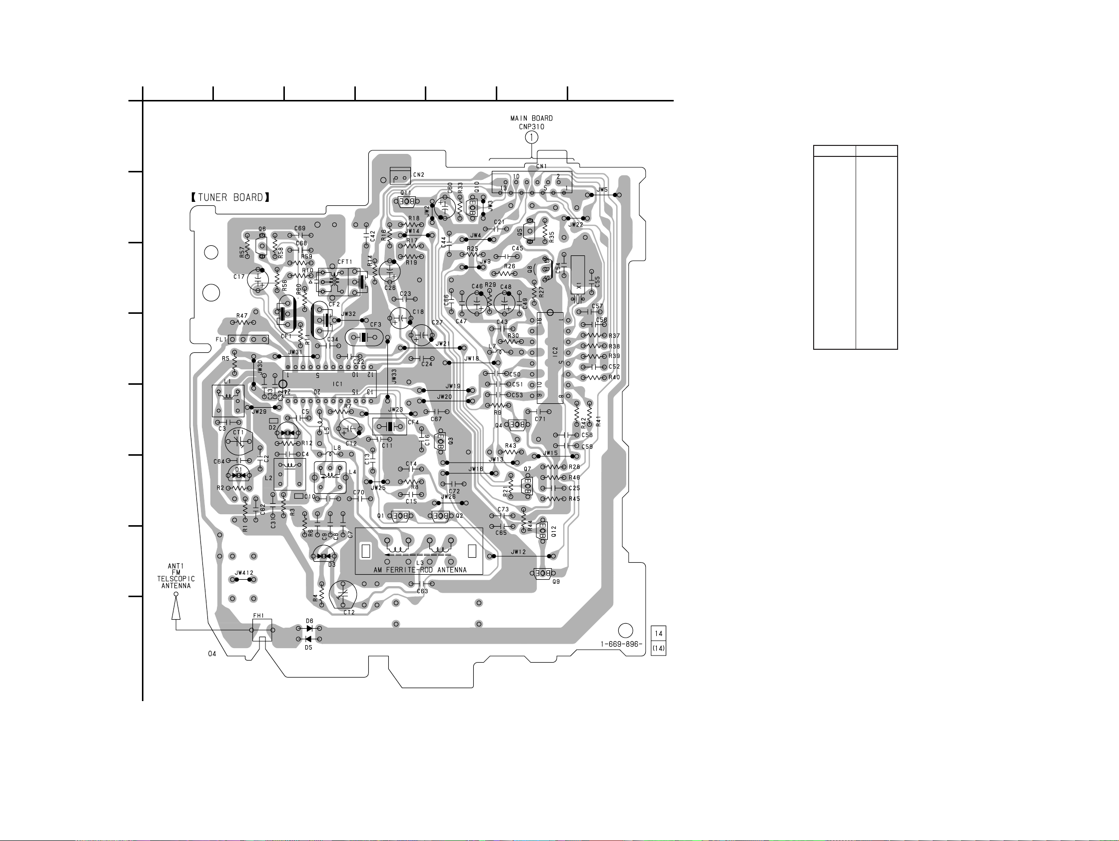
– TUNER BOARD (COMPONENT SIDE) –
TUNER Board Part No.
Former type : 1-669-896-11
New type (E) : 1-669-896-14
– CD BOARD (COMPONENT SIDE) –
TUNER Board Part No.
Former type : 1-669-896-11
New type (US) : 1-674-113-11
CD Board Part No.
Former type : 1-667-507-11
New type : 1-667-507-12
– 2 –
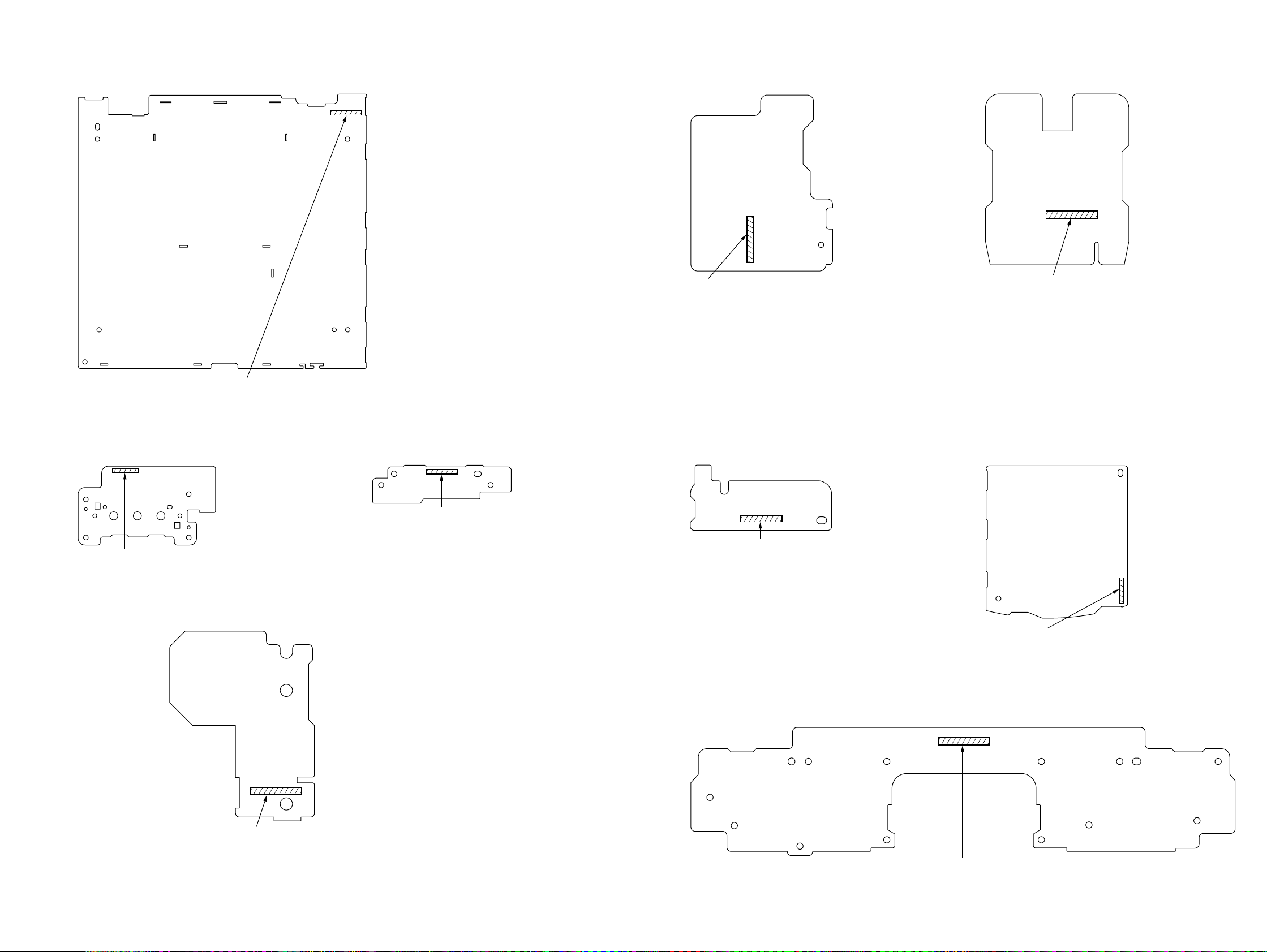
– MAIN BOARD (COMPONENT SIDE) –
–
–
–
–
CONTROL Board Part No.
Former type : 1-667-504-11
New type : 1-667-504-12
– CONTROL BOARD (COMPONENT SIDE) –
– HEADPHONE BOARD (COMPONENT SIDE)
– BACK UP BOARD (COMPONENT SIDE)
MAIN Board Part No.
Former type : 1-669-895-11
New type (E) : 1-669-895-14
New type (US) : 1-674-112-11
– LCD BOARD (COMPONENT SIDE) –
LCD Board Part No.
Former type : 1-667-506-11
New type : 1-667-506-12
– LAMP BOARD (COMPONENT SIDE) –
LAMP Board Part No.
Former type : 1-669-901-11
New type (E) : 1-669-901-14
New type (US) : 1-674-118-11
HEADPHONE Board Part No.
Former type : 1-669-900-11
New type (E) : 1-669-900-14
New type (US) : 1-674-117-11
– BATTERY BOARD (COMPONENT SIDE)
BATTERY Board Part No.
Former type : 1-667-499-11
New type : 1-667-499-12
BACK UP Board Part No.
Former type : 1-667-500-11
New type : 1-667-500-12
– POWER BOARD (COMPONENT SIDE) –
– RECORD/PLAYBACK
SWITCH BOARD (COMPONENT SIDE)
RECORD/PLAYBACK
SWITCH Board Part No.
Former type : 1-669-898-11
New type (E) : 1-669-898-14
New type (US) : 1-674-115-11
POWER Board Part No.
Former type : 1-669-897-11
New type (E) : 1-669-897-14
New type (US) : 1-674-114-11
– 3 – – 4 –
CFD-W57
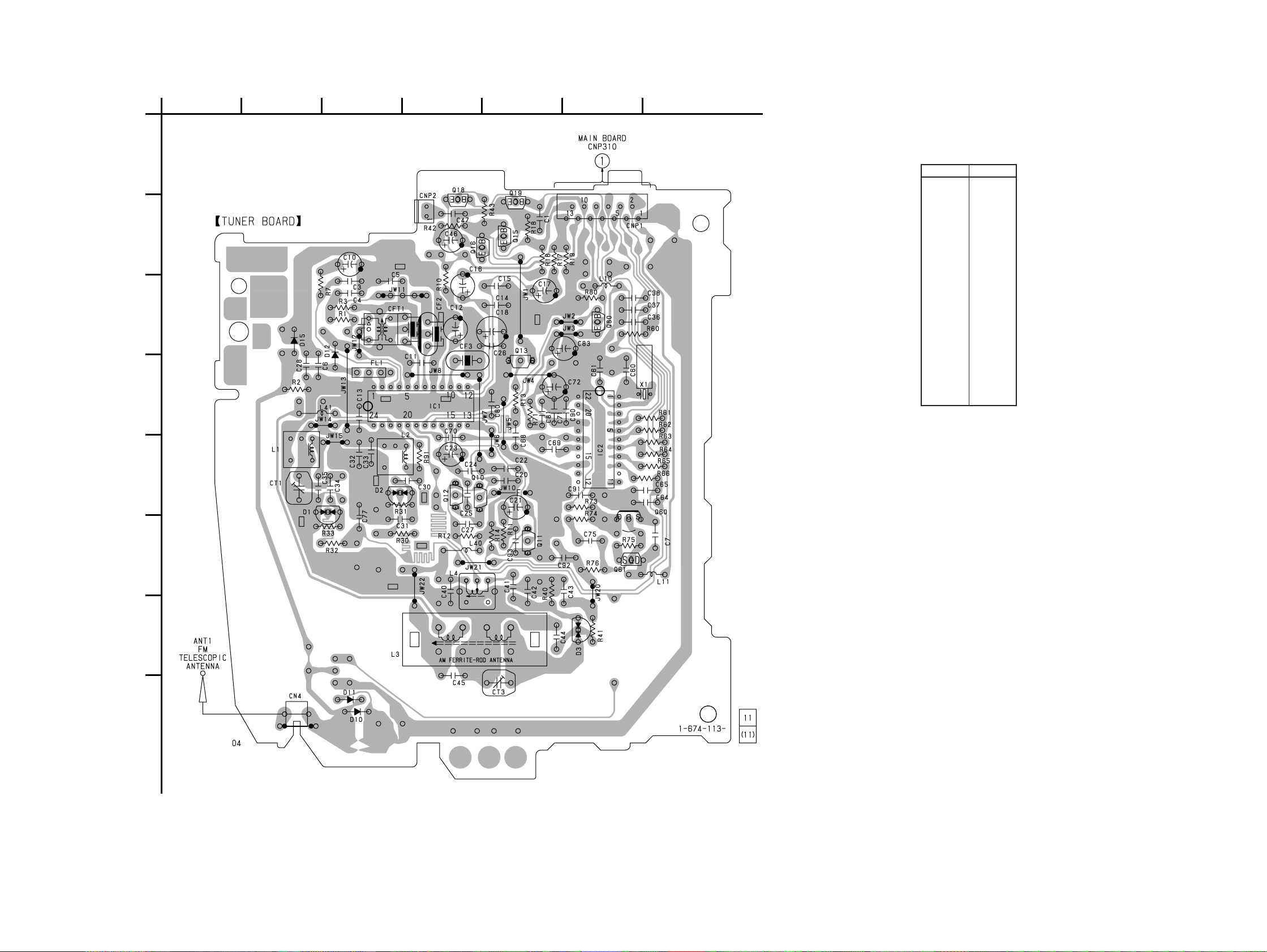
1. PRINTED WIRING BOARD — TUNER SECTION — (US Model)
A
B
C
D
1
234567
(Page 19)
• Semiconductor
Location
Ref. No. Location
D1 E-3
D2 E-3
D3 G-6
D10 H-3
D11 H-3
D12 C-3
D15 C-2
IC1 D-4
IC2 D-6
Q10 E-4
Q11 F-5
Q12 E-4
Q13 D-5
Q15 B-5
Q16 B-4
Q18 A-4
Q19 A-5
Q60 E-6
Q61 F-6
Q80 C-6
E
F
G
H
Note on Printed Wiring Boards:
• X : parts extracted from the component side.
• W : indicates side identified with part number.
f
•
• b : Pattern from the side which enables seeing.
Note on Schematic Diagram:
• All capacitors are in µF unless otherwise noted. pF: µµF
• All resistors are in Ω and 1/
•
• U : B+ Line.
• Voltage is dc with respect to ground under no-signal
• Voltages are taken with a VOM (Input impedance 10 MΩ).
• Signal path.
: internal component.
50 WV or less are not indicated except for electrolytics
and tantalums.
specified.
f
: internal component.
(detuned) condition.
no mark : FM
( ) : AM
Voltage variations may be noted due to normal production tolerances.
F : FM
f : AM
4
W or less unless otherwise
– 5 – – 6 –
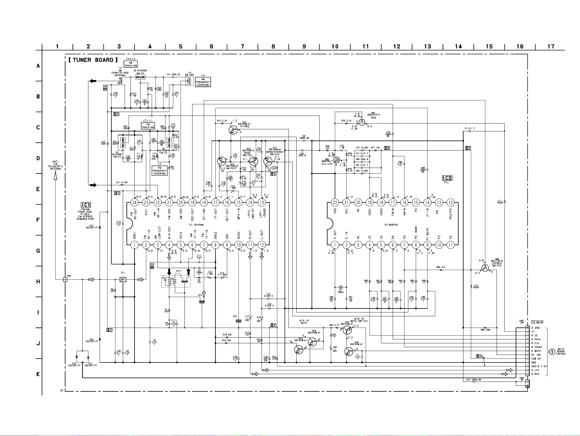
2. SCHEMATIC DIAGRAM — TUNER SECTION — (US Model)
CFD-W57
– 7 – – 8 –
(Page 25)
CFD-W57
3. PRINTED WIRING BOARD — TUNER SECTION — (E Model)
A
B
C
D
1
234567
(Page 22)
• Semiconductor
Location
Ref. No. Location
D1 F-2
D2 E-2
D3 G-3
D5 H-3
D6 H-3
IC1 D-3
IC2 D-6
Q1 F-4
Q2 F-5
Q3 E-5
Q4 E-6
Q5 B-6
Q6 B-2
Q7 F-6
Q8 C-6
Q9 G-6
Q10 B-5
Q11 B-4
Q12 G-6
E
F
G
H
Note on Printed Wiring Boards:
• X : parts extracted from the component side.
• W : indicates side identified with part number.
f
•
• b : Pattern from the side which enables seeing.
Note on Schematic Diagram:
• All capacitors are in µF unless otherwise noted. pF: µµF
• All resistors are in Ω and 1/
•
• U : B+ Line.
• Voltage is dc with respect to ground under no-signal
• Voltages are taken with a VOM (Input impedance 10 MΩ).
• Signal path.
: internal component.
50 WV or less are not indicated except for electrolytics
and tantalums.
specified.
f
: internal component.
(detuned) condition.
no mark : FM
( ) : AM
Voltage variations may be noted due to normal production tolerances.
F : FM
f : AM
4
W or less unless otherwise
– 9 – – 10 –
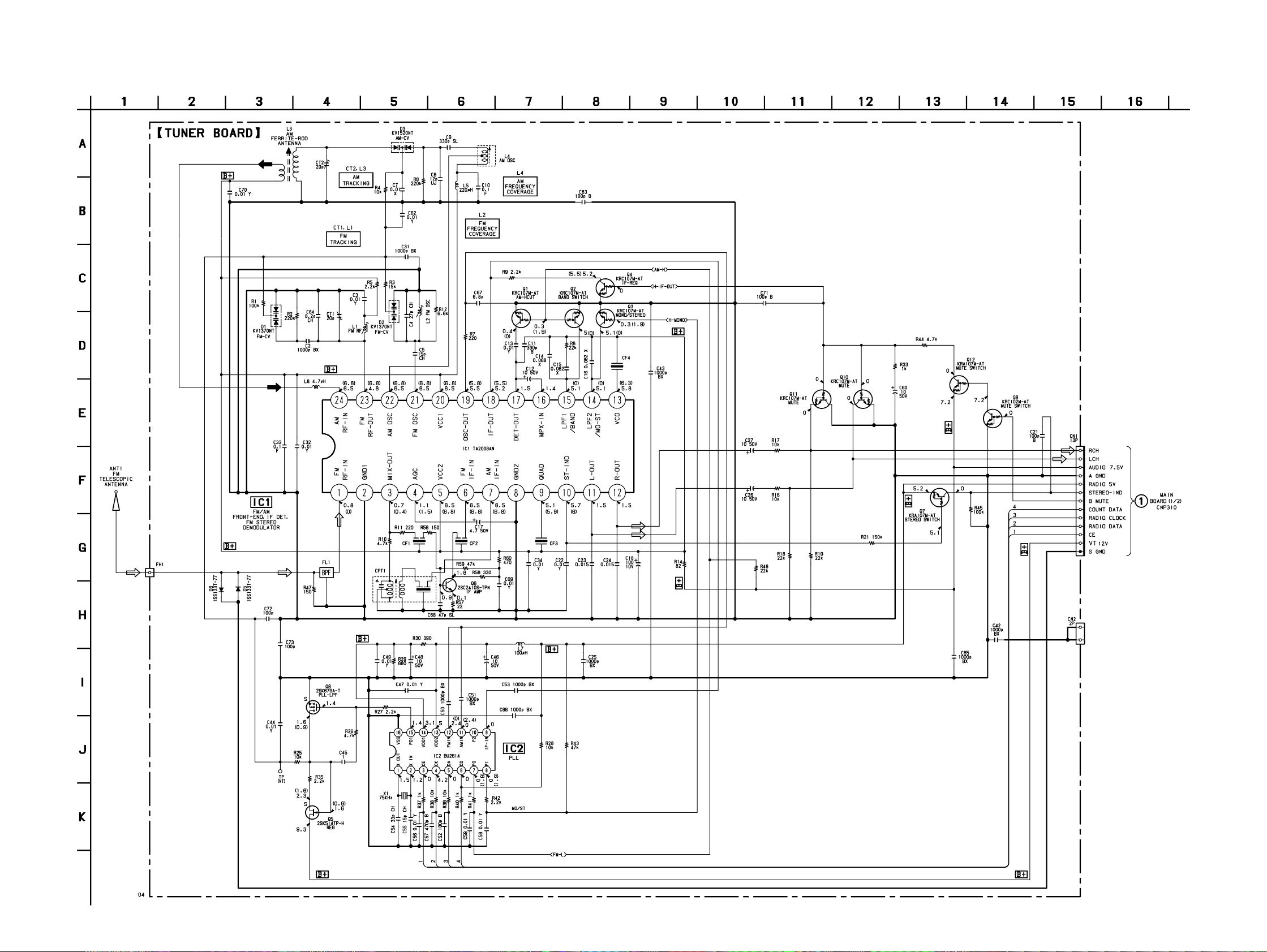
4. SCHEMATIC DIAGRAM — TUNER SECTION — (E Model)
CFD-W57
(Page 25)
– 11 – – 12 –
 Loading...