

Page 1
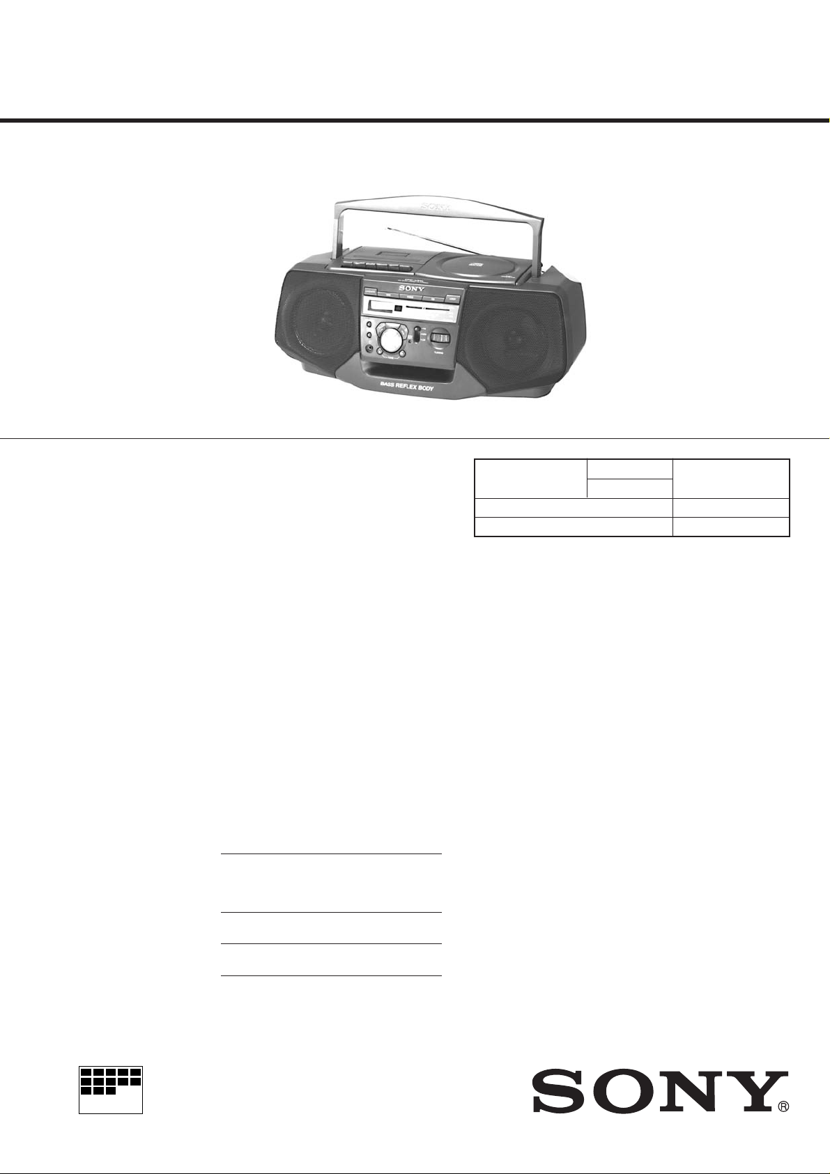
CFD-V34L
SERVICE MANUAL
Ver 1.1 1998.08
With SUPPLIMENT-1
(9-923-378-81)
AEP Model
UK Model
E Model
Model Name Using
Similar Mechanism
Optical Pick-up Type KSM-213CDM/C2NP
Tape Transport Mechanism Type MF-V10-117
CD Section
Tape Section
NEW
SPECIFICATIONS
CD player section
System Compact disc digital audio system
Laser diode properties Material : GaAlAs
Wavelength :780 nm
Emission duration : Continuous
Laser output : Less than 44.6 µW
(This output is the value measured at a distance
of about 200 mm from the objective lens surface
on the optical pick-up block with 7 mm
aperture.)
Spindle speed 200 r/min (rpm) to 500 r/min (rpm) (CLV)
Number of channels 2
Frequency response 20 – 20,000 Hz + 1/-2 dB
Wow and flutter Below measurable limit
Radio section
Frequency range
FM Italy 87.5 – 108 MHz
Central and 65 – 108 MHz
Eastern Europe
Other countries 87.6 – 107 MHz
MW Italy 526.5 – 1606.5 kHz
Other countries 531 – 1,602 kHz
LW Italy 148.5 – 283.5 kHz
Other countries 153 – 279 kHz
IF FM : 10.7 MHz
AM/MW/LW : 455 kHz
Aerials FM : Telescopic aerial
AM/MW/LW : Built-in ferrite bar aerial
Cassette-corder section
Recording system 4 -track 2 channel stereo
Fast winding time Approx. 120 s (sec.) with Sony cassette
C-60
Frequency response TYPE1 (normal) : 70 – 10,000 Hz
General
Speakers Full range : 10 cm dia., 3.2 Ω, cone type
(2)
Outputs Headphones jack (stereo minijack)
For 16 – 64 Ω impedance headphones
Maximum Power output 2.5 W + 2.5 W
Power requirements For CD radio cassette-corder :
230V AC, 50 Hz
9V DC, 6 R 20 (size D) batteries
For memory controller :
3V DC, 2 R 6 (size AA) batteries
Power consumption AC 20W
— Continued on next page —
CD RADIO CASSETTE-CORDER
MICROFILM
Page 2

Battery life For CD radio cassette-corder:
TABLE OF CONTENTS
1. SERVICE NOTES ···························································· 3
FM recording
Sony R20P : approx. 13.5 h
Sony alkaline LR20 : approx. 19 h
Tape playback
Sony R20P : approx. 7.5 h
Sony alkaline LR20 : approx. 15 h
CD playback
Sony R20P : approx. 2.5 h
Sony alkaline LR20 : approx. 6 h
Dimensions Approx. 425 × 160 × 246 mm (w/h/d)
(16 3/4 × 6 3/8 × 9 3/4 inches) (incl. projecting
parts)
Mass Approx. 4.2 kg (9 lb. 4 oz) (incl. batteries)
Supplied accessories AC power cord (1)
Remote controller (1)
Design and specifications are subject to change without notice.
Optional accessories
Sony MDR headphones series
2. GENERAL ·········································································· 4
3. DISASSEMBL Y
3-1. Front Cabinet, Control (1) Board, Control (2) Board,
Headphones Board ····························································· 9
3-2. Upper Cabinet····································································· 9
3-3. Optical Pick-up ································································· 10
3-4. Mechanism Deck, Rec sw Board, Main Board,
Power Board, Primary Board, Batt Board ························ 10
4. ADJUSTMENTS
4-1. Mechanical Adjustment ···················································· 11
4-2. Electrical Adjustment ······················································· 11
4-3. Tuner Section····································································12
4-4. Reference ·········································································· 15
5. DIAGRAMS
5-1. Circuit Board Location ····················································· 17
5-2. IC Pin Function ································································ 18
5-3. Block Diagram ································································· 20
5-4. Printed Wiring Board ························································ 23
5-5. Schematic Diagram – Tuner/System Section – ················ 27
5-6. Schematic Diagram – Power Section – ···························· 31
5-7. Schematic Diagram – CD Section – ································· 35
5-8. IC Block Diagrams ··························································· 38
6. EXPLODED VIEWS
6-1. Front Cabinet Section ······················································· 39
6-2. Upper Cabinet Section······················································ 40
6-3. Rear Cabinet Section ························································ 41
6-4. Mechanism Deck Setion (1) (MF-V10-117) ···················· 42
6-5. Mechanism Deck Setion (2) (MF-V10-117) ···················· 43
6-6. Optical Pick-up Section (KSM-213CDM/C2NP) ············ 44
7. ELECTRICAL PARTS LIST······································· 45
SAFETY-RELATED COMPONENT WARNING!!
COMPONENTS IDENTIFIED BY MARK ! OR DOTTED LINE WITH
MARK ! ON THE SCHEMATIC DIAGRAMS AND IN THE PARTS
LIST ARE CRITICAL TO SAFE OPERATION. REPLACE THESE
COMPONENTS WITH SONY PARTS WHOSE PART NUMBERS
APPEAR AS SHOWN IN THIS MANUAL OR IN SUPPLEMENTS
PUBLISHED BY SONY.
— 2 —
Page 3
SECTION 1
SERVICE NOTES
Laser component in this product is capable
of emitting radiation exceeding the limit for
Class 1.
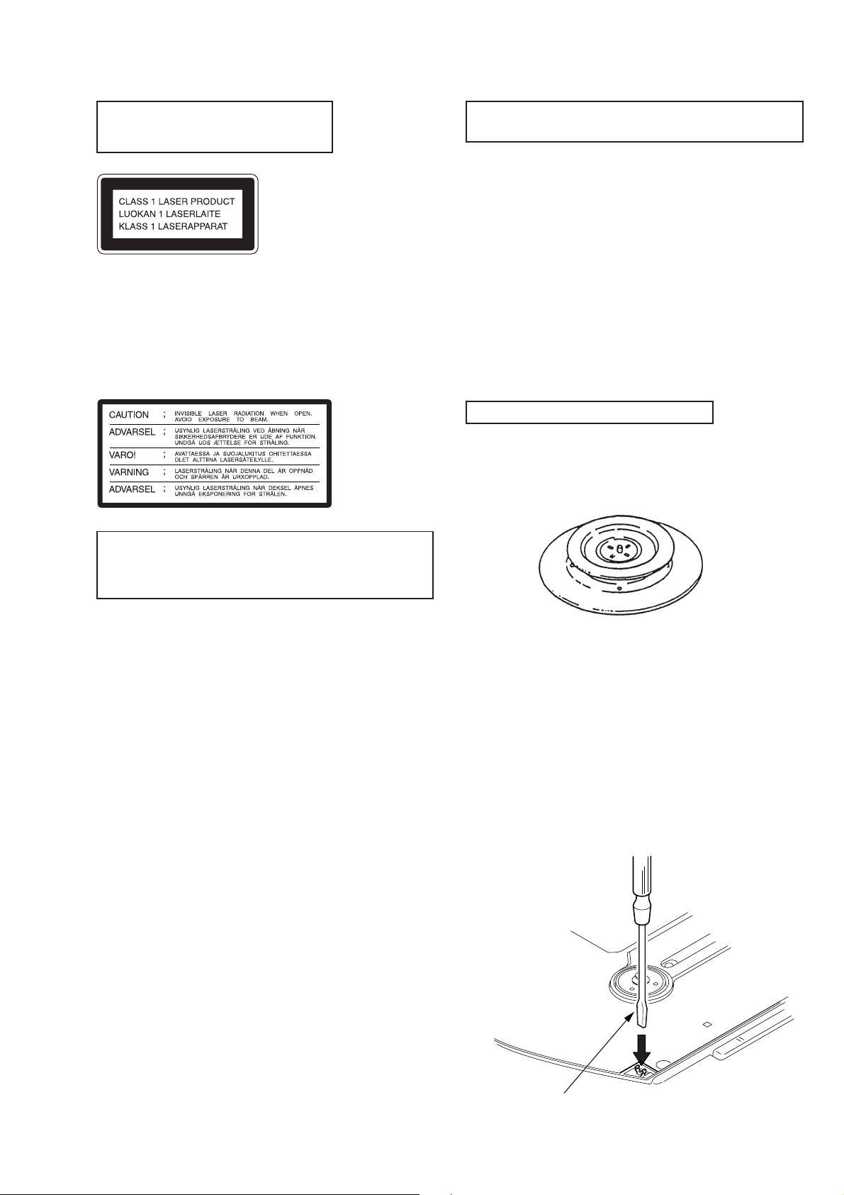
This appliance is classified as a CLASS 1 LASER product. The
CLASS 1 LASER PRODUCT MARKING is located on the rear
exterior.
The following caution label is located inside the unit.
NOTES ON HANDLING THE OPTICAL PICK-UP
BLOCK OR BASE UNIT
The laser diode in the optical pick-up block may suffer electrostatic
breakdown because of the potential difference generated by the
charged electrostatic load, etc., on clothing and the human body.
During repair, pay attention to electrostatic breakdown and also use
the procedure in the printed matter which is included in the repair
parts.
The flexible board is easily damaged and should be handled with
care.
NOTES ON LASER DIODE EMISSION CHECK
The laser beam on this model is concentrated so as to be focused on
the disc reflective surface by the objective lens in the optical pickup block. Therefore, when checking the laser diode emission,
observe from more than 30 cm away from the objective lens.
CHUCK PLA TE JIG ON REPAIRING
On repairing CD section, playing a disc without the CD lid, use
Chuck Plate Jig.
• Code number of Chuck Plate Jig : X-4918-255-1
CAUTION
Use of controls or adjustments or performance of procedures
other than those specified herein may result in hazardous radiation
exposure.
LASER DIODE AND FOCUS SEARCH OPERATION
CHECK
1. Press CD open knob.
2. Open the lid for CD.
3. Push on SWITCH as following figure.
4. Confirm the laser diode emission while observing the objecting
lens. When there is no emission, Auto Po wer Control circuit or
Optical Pick-up is broken.
Objective lens moves up and down once for the focus search.
— 3 —
Insert a precision screw driver
and push SWITCH
Page 4
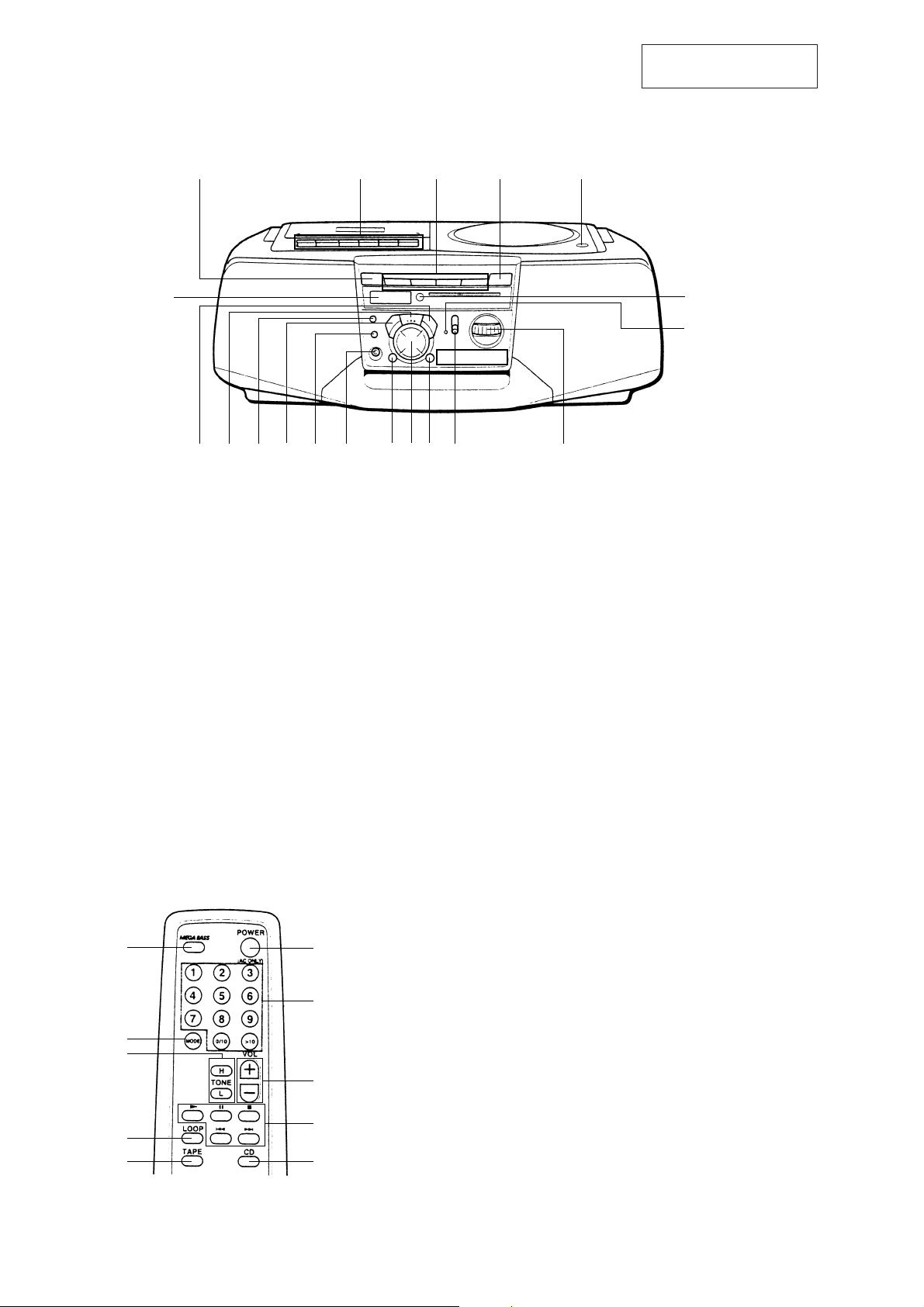
LOCA TION OF CONTROLS
SECTION 2
GENERAL
This section is extracted
from instruction manual.
54321
!ª
!• !¶ !§ !∞ !¢ !£ !™ !¡ !º 9 8
1 OPERATE button
2 Tape operating buttons
3 FUNCTION buttons
4 LOOP button
5 OPEN/CLOSE button
6 Remote sensor
7 OPR/BATT indicator
8 TUNING knob
9 Band select knob (FM – MW – LW)
!º TONE (H) button
6
7
!¡ CD operating
!™ TONE (L) button
!£ 2
!¢ DISPLAY/ENTER button
!∞ VOLUME – button
!§ PLAY MODE button
!¶ MEGA BASS button
!• VOLUME + button
!ª Information display
Remote commander (RMT-CV25AD)
!º
9
8
7
1
2
3
4
56
1 POWER (AC ONLY) button
2 Number buttons
3 VOL +/– buttons
4 CD operation buttons
5 CD button
6 TAPE button
7 LOOP button
8 TONE H/L buttons
9 MODE button
!º MEGA BASS button
— 4 —
Page 5
— 5 —
Page 6
— 6 —
Page 7
— 7 —
Page 8
— 8 —
Page 9
SECTION 3
D
4
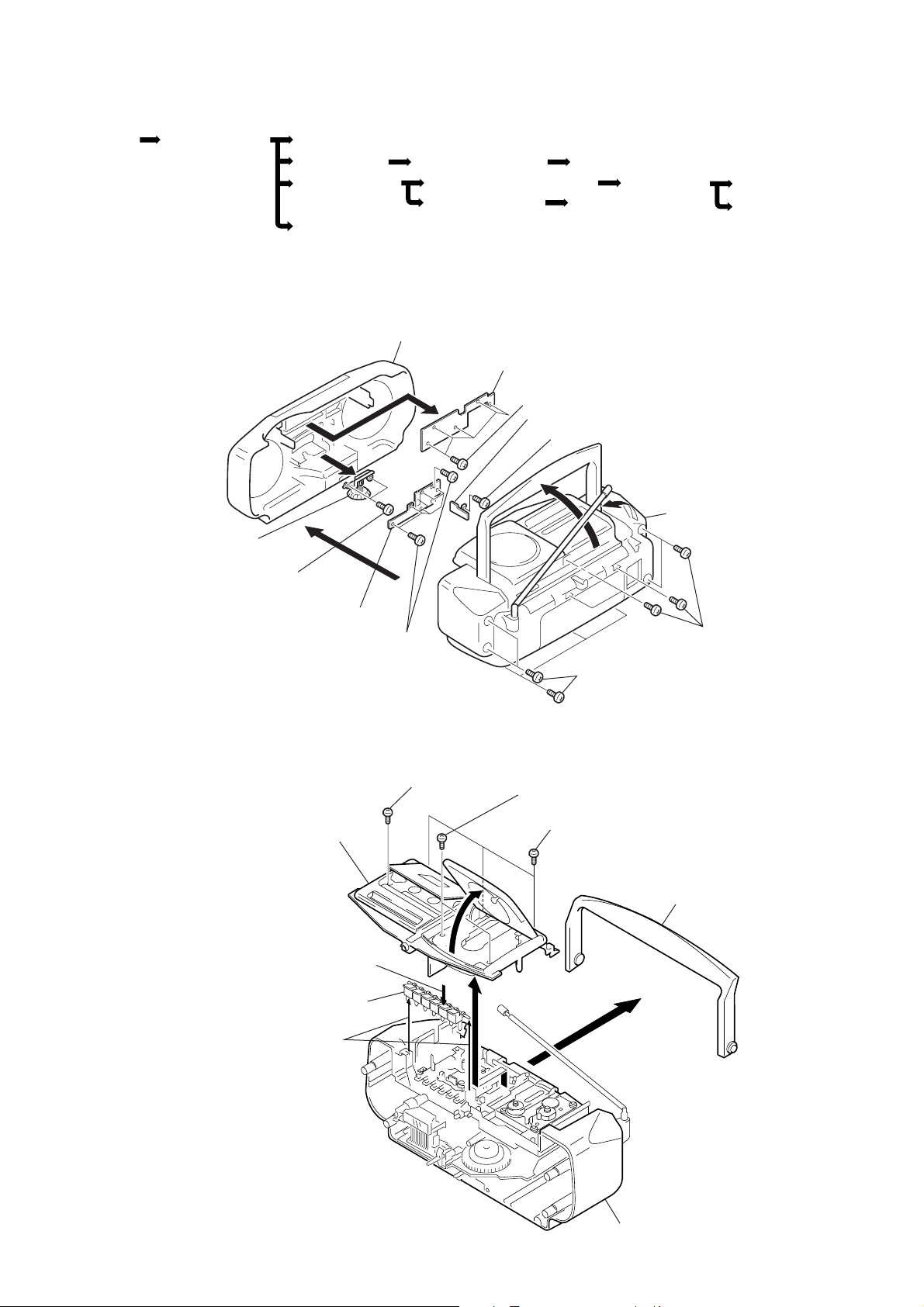
DISASSEMBLY
• The equipment can be removed using the following procedure.
SET FRONT CABINET CONTROL (1) BOARD
TUNING KNOB
UPPER CABINET
PRIMARY BOARD
Note : Follow the disassembly procedure in the numerical order given.
3-1. FRONT CABINET, CONTROL (1) BOARD, CONTROL (2) BOARD, HEADSPHONES BOARD
CONTROL (2) BOARD HEADPHONES BOARD
OPTICAL PICK-UP SECTION
MECHANISM DECK
Front cabinet
6
CONTROL (1) board
5
Screws +BVTP 2.6 × 8
REC SW BOARD
!™
Headphones board
!¡
Screw +BVTP 2.6 × 8
1
MAIN BOARD POWER BOAR
BATT BOARD
2
Rear cabinet
8
TUNING KNOB
7
Screws
+BVTP 2.6 × 8
3-2. UPPER CABINET
Cabinet (upper) assy
4
!º
CONTROL (2)
board
2
STOP/EJECT
9
Screws
+BVTP 2.6 × 8
4
Screw
+BVTP 3
3
Screws
+BVTP 3 × 1
3
Screws +BVTP 3 × 14
4
×
12
3
Screws
+BVTP 3 × 10
1
Screws
+BVTP 3 × 12
Handle
Tape operation button
7
5
— 9 —
6
Rear cabinet
Page 10
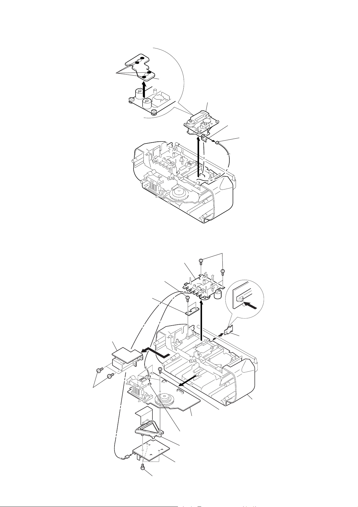
3-3. OPTICAL PICK-UP
0
4
Remove solder
5
CD Motor
board
Optical pick-up section
3
Wire (Flat type) (16 core)
to MAIN board (CNP701)
1
2
CNP702 (6pin)
3-4. MECHANISM DECK, REC SW BOARD, MAIN BOARD, POWER BOARD, PRIMARY BOARD,
BA TT BOARD
PRIMARY board
!™
Screws
+BVTP 3 × 10
3
Screws +BVTP 3 × 10
REC SW board
!£
Mechanism deck
2
4
MAIN board
1
Screws +BVTP 3 × 1
!º
!¡
BATT board
Rear cabinet
6
Screws +BVTP 3 × 10
5
CNP301 (4pin)
7
Chassis (PWB)
9
POWER board
8
Screws +BVTP 3 × 10
— 10 —
Page 11
SECTION 4
ADJUSTMENTS
4-1. MECHANICAL ADJUSTMENT
PRECAUTION
1. Clean the following parts with a denatured-alchool-moistened
swab:
record/playback head pinch roller
erase head rubber belts
capstans
2. Demagnetize the record/playback head with a head
demagnetizer. (Do not bring the head demagnetizer close to
the erase head.)
3. Do not use a magnetized screwdriver for the adjustments.
4. After the adjustments, apply suitable locking compound to the
parts adjusted.
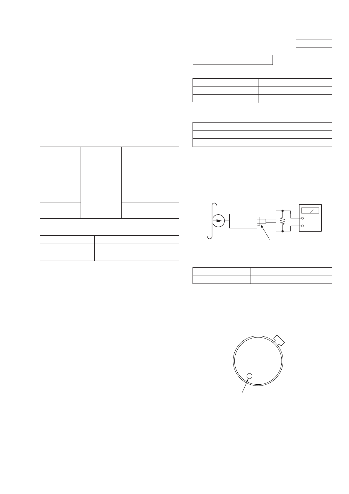
T orque Measurement
Mode
FWD
FWD
back tension
Fast Forward
Rewind
T ape T ension Measurement
Torque Meter
CQ-102C
CQ-201B
Meter Reading
60g•cm
(0.42 – 0. 83 oz•inch)
1 – 5g•cm
(0.014 – 0.07 oz•inch)
more than 55g•cm
(more than 0.77 oz•inch)
more than 55g•cm
(more than 0.77 oz•inch)
4-2. ELECTRICAL ADJUSTMENT
T APE RECODER SECTION
Standard output level
Output Pin
Load impedance
Output signal level
Test tape
Test Tape
WS-48A
P-4-A063
Tape Speed Adjustment
Procedure :
Mode : Playback
test tape
WS-48A
(3kHz, 0dB)
Signal
3kHz, 0dB
6.3kHz, –10dB
set
0.25 V (–10dB)
Tape speed adjustment
Head azimuth adjustment.
32
0dB = 0.775V
HP OUT
32 Ω
Used for
digital frequency
counter
Ω
+
–
Torque Meter
CQ-403A
Meter Reading
more than 80g
(more than 2.83 oz)
J302 (phones)
Adjustment V alue : normal tape speed
Speed checker
–2.0 to 2.0%
Frequency difference between the beginning and the end of the
tape should be within 2% (60Hz).
Adjustment Location :
Tape speed adjustment
control inside motor
Digital frequency counter
2,940 – 3,060Hz
— 11 —
Page 12

4-3. TUNER SECTION
• Switch Location
VOLUME : MAX
MEGA BASS : OFF
PRESET SOUND MODE : OFF
AM SECTION
BAND : AM
Signal generator
AM RF signal
generator
30% amplitude modulation by 400Hz
signal.
Output level : as low as possible
FM SECTION
Put the lead-wire
antenna close to
the set.
0 dB = 1 µV
• Repeat the procedures in each adjustment several times for the
maximum level meter indication.
• The frequency coverage and tracking adjustments should be
finally done by the trimmer capacitors.
AM IF ALIGNMENT
Adjust for a maximum reading on level meter.
T2 455 kHz
( ): Italian model
MW/AM RECEPTION FREQUENCY COVERAGE CHECK
Frequency indication 520 kHz (516 kHz) 1,680 kHz
Adjustment L4 CV1 (4/4)
( ): Italian model < >: East European model
LW RECEPTION FREQUENCY COVERAGE CHECK
Frequency indication 145 kHz (140 kHz) 300 kHz (293 kHz)
< 520 kHz > < 1,680 kHz >
Adjustment L11 CT8
BAND : FM
Signal generator
FM RF signal
generator
0.01µF
75kHz (100%) amplitude modulation
by 1kHz signal.
Output level : as low as possible
32k
Ω
set
J302 (phones)
telescopic
antenna
terminal
level meter
+
–
Adjustment Location : MAIN board (Component side)
(See page 13)
MW/AM TRACKING ADJUSTMENT
Adjust for a maximum defection of level meter.
L3 CV1 (3/4)
620 kHz 1,400 kHz
L W TRACKING ADJUSTMENT
Adjust for a maximum defection of level meter.
L3 CT7
160 kHz 260 kHz
FM IF ADJUSTMENT
Adjust for a maximum reading on level meter.
T1 10.7 MHz
( ): Italian model < >: East European model
FM RECEPTION FREQUENCY COVERAGE CHECK
Frequency 87.0 MHz 108.3 MHz (108.25 MHz)
indication < 64.0 MHz > < 109.5 MHz >
Adjustment L2 CV1 (2/4)
( ): Italian model < >: East European model
— 12 —
FM TRACKING ADJUSTMENT
Adjust for a maximum defection of level meter.
L1 CV1 (1/4)
87.0 MHz (87.35 MHz) 108.3 MHz (108.25 MHz)
< 68.0 MHz > < 102 MHz >
Page 13

FM VCO Adjustment
l
r
color
mark
CF1
Procedure :
FM RF SSG
0.01µF
to ANT IN termina
Carrier frequency : 98MHz
IF frequency : According to
the color of CF1.
Modulation : no modulation
Output level : 0.1V (100dB)
1. Connect frequency counter to the positions shown below.
2. Tune the set to 98MHz.
3. Adjust RV1 for 75.950kHz to 76.050kHz reading on the
frequency counter.
Frequency counte
IC1 Pin
IC1 Pin
4
7
0.01µF
33k
Ω
+
–
Adjustment Location : MAIN board (Component side)
RED 10.70MHz
BLUE 10.67MHz
ORANGE 10.73MHz
BLACK 10.64MHz
WHITE 10.76MHz
FM Reception Frequency
Coverage Check
L2
MW/AM Tracking Adjustment
L3 (MW)
CV1 (3/4)
RV1 : FM VCO
T1
L3
RV1
30
1
4
IC701
CV1 (2/4)
L2
18
11
CV1 (1/4)
CV1
IC1
FM Tracking
CT7
L1
T2
MW/AM Reception Frequency
Coverage Check
L1
CT8
L4
L4CV1 (4/4)
L11
LW Reception Frequency
Coverage Check
L11CT8
ANT IN
T1 : FM IF
IC1 : VCO IN
L3 (LW)
LW Tracking Adjustment
CT7
— 13 —
’ ‘
FM IF IN
T2 : AM IF
Page 14

CD SECTION
V
e
Notes on Check
1. Perform the traverse check in the CD test mode.
After check, be sure to exit the test mode.
2. Perform check in the order given.
3. Use the disc (YEDS-18, Parts No. 3-702-101-01) only when
so indicated.
Before Check
Put the set into test mode and perform the following checks.
Repair if there are any problems.
• Sled Motor Check
Press + , = keys and confirm that the Optical pick-up moves
smoothly from the innermost to outermost circumference and back
smoothly and with no catching or abnormal noises.
(Cancellation of BTL mute)
+ : Optical pick-up moves to the outer circumference.
= : Optical pick-up moves to the inner circumference.
E-F Balance Check
Adjustment Location : MAIN board (See page 23)
This check is to be done when the optical pick-up block is replaced.
Check Procedure:
1. Connect the oscilloscope to test point TP (VC) and TP (TE) on
MAIN board.
2. Put the set into test mode.
3. Optical pick-up setting to the center by + or = button
pushing.
4. Insert disk (YEDS-18) and press ^ button.
5. Check that the oscilloscope traverse wav eform is symmetrical,
as shown in the figure below.
6. Release test mode after adjustment is completed.
A
VOLT/DIV : 0.1
0V
TIME/DIV : 1ms
B
• Focus Search Check
1. Press the CD ^ key. (Focus search operation is performed
continuously.)
2. Look at the Optical pick-up objective lens and confirm that it
moves up and down smoothly, with no catching or abnormal
noises.
3. Press p button.
Confirm that focus search operation stops. If it does not, press
p button again longer.
How to Enter the Set into T est Mode
1. Turn the AC CORD IN (Adaptor).
(LCD 501 indicator blinks the test mode pattern.)
2. Short-circuit between the lands as shown on the control (1)
board.
How to Exit the T est Mode
Turn the POWER OFF.
[CONTROL (1) BOARD]
A = B C = 400mV to 600mV
[MAIN BOARD]
TP(RF)
C
TP(FE)
TP(VC)
TP(TE)
Osilloscop
(DC range)
Test portion
Short : Test mode
Open : Normal mode
Jumper wire
— 14 —
TP(TE)
TP(VC)
+
–
Page 15

Focus Bias Check
(
Adjustment Location : MAIN board (Component side)
(See page 23)
This check is to be done when the optical block replaced.
Check Procedure:
1. Connect the oscilloscope to test point TP (VC) and TP (RF) on
MAIN board.
2. Put the set into test mode.
3. Opitical pick-up setting to the center by + or – button pushing.
4. Insert disk (YEDS-18) and press ^ button.
5. Press the MODE button. (Tracking servo ON)
6. Check that the oscilloscope wa vewform is as sho wn in the figure
below (eye pattern).
A good eye pattern means that the diamond shape (◊) in the
center of the waveform can be clearly distinguished.
7. Release test mode after adjustment is completed.
• RF signal reference waveform (eye pattern)
VOLT/DIV : 0.2V
TIME/DIV : 500ns
1.0 to 1.4 Vp-p
When observing the eye pattern, set the oscilloscope for AC range
and raise vertical sensivity.
[MAIN BOARD]
TP(FE)
TP
4-4. REFERENCE
Focus/Tracking Gain Check
Adjustment Location : MAIN board (Component side)
(See page 23)
A frequency response analyzer is necessary in order to perform this
check exactly.
However , this gain has a mar gin, so e ven if it is slightly off, there is
no problem.
Focus/Tracking gain determines the pick-up follo w-up (vertical and
horizontal) relative to mechanical noise and mechanical shock when
the 2-axis device operate.
Symptoms
Gain
Focus
• The time until music starts
becomes longer for STOP ➡
CD ^ or automatic
selection (0 , ) buttons
low
pressed). (Normally takes
about 2 seconds.)
• Music does not start and disc
continues to rotate for STOP
➡ CD ^ or automatic
—
selection (0 , ) buttons
pressed.)
• Sound is interrupted during
PLAY. Or time counter
—
display stops progressing.
• More noise during 2-axis
device operation.
high
Check Procedure:
1. Keep the set horizontal.
2. Inset disk (YEDS-18) and press ^ button.
3. Connect an oscilloscope to TP (FE) and TP (VC) on the MAIN
board.
4. Check that the w aveform is as sho wn in the figure below . (Focus
waveform)
Tracking
low or high
low
low
high
TP(RF)
TP(TE)
Osilloscope
(DC range)
+
–
— 15 —
Page 16

• Good Example
V
V
V
s
s
e
• Incorrect Examples (Fundamental wave appears)
VOLT/DIV : 100m
TIME/DIV : 1ms
100mV
0V
• Incorrent Examples (DC level changes more than on adjusted
waveform)
VOLT/DIV : 100m
TIME/DIV : 2ms
200mV
0V
low focus gain
VOLT/DIV : 100m
TIME/DIV : 2ms
75mV
0V
VOLT/DIV : 1V
TIME/DIV : 2ms
0V
low tracking gain
VOLT/DIV : 1V
TIME/DIV : 2m
0V
high tracking gain
(high fundamental wave than for low gain)
[MAIN BOARD]
TP(FE)
TP(VC)
high focus gain
5. Connect an oscilloscope between TP (TE) and TP (VC).
6. Insert disc (YEDS-18) and press the CD ^ button.
7. Check that the waveform is as shown in the figure below.
(tracking waveform)
VOLT/DIV : 1V
TIME/DIV : 2m
0V
TP(RF)
TP(TE)
TP(VC)
TP(TE)TP(FE)
Osilloscop
(DC range)
+
–
— 16 —
Page 17

5-1. CIRCUIT BOARDS LOCA TION
PRIMARY board
SECTION 5
DIAGRAMS
REC SW board
BATT board
CONTROL (1) board
RMC board
JUCK RETAINER board
HEADPHONE board
CD MOTOR board
MONO/ST board
MAIN board
CONTROL (2) board
POWER board
— 17 —
Page 18

5-2. IC PIN FUNCTION
IC501 CXP83416
Pin No.
1
2
3
4
5
6
7
8
9
10
11
12
13
14
15
16
17
18
19
20
21
22
23
24
25
26
27
28
29
30
31
32
33
34
35
36
37
38
39
40
Pin Name
C-SCOR
RMC
C-XRST
B-MUTE
ROCK
POP
C-SQCK
C-SQSO
REC
C-SENS
C-SENS2
CD-PLAY
CD-STOP
C-CLK
C-XLT
C-DATA
MEGA BASS
TONE +
TONE –
VOL +
VOL –
MODE CHK
C-DOOR
BAND CHK
CD KEY
TAPE
FM/RADIO
AM
CD
RST
4.19 MHz
4.19 MHz
Vss
VL
VLC3
VLC2
VLC1
COM0
COM1
COM2
I/O
I
SCOR input to CD
I
Remote control signal input
O
Reset output to CD system
O
CD block mute ON/OFF
I/O
Input from ROCK key
I/O
Input from POP key
I/O
Clock for reading CD SUBQ
I/O
CD SUBQ data input
I/O
Input from TAPE REC switch
I/O
CD SENS input
I/O
CD SENS2 input
I/O
Input from CD-PLAY key
I/O
Input from CD-STOP key
I/O
Clock for CD DSP command
I/O
Latch output from CD system
I/O
Command data output from CD DSP
I/O
Input from MEGA BASS switch
I/O
Input from TONE + key
I/O
Input from TONE – key
I/O
Input from VOL + key
I/O
Input from VOL – key
I/O
Mode check from RADIO/SOUND
I/O
Open/close sense from CD door
I/O
Input from RADIO BAND switch
I/O
Input from CD key (A/D)
I/O
Input from TAPE FUNCTION key
I/O
Input from FM/RADIO key
I/O
Input from AM FUNCTION key
I/O
Input from CD FUNCTION key
I
Reset input
I
4.19 MHz input
O
4.19 MHz output
—
Microprocessor reference GND
O
ON/OFF terminal of LCD drive port
I
LCD drive voltage terminal
I
LCD drive voltage terminal
I
LCD drive voltage terminal
O
LCD common output port
O
LCD common output port
O
LCD common output port
Description
— 18 —
Page 19

5-3. BLOCK DIAGRAM
CFD-V34L
Pin No.
41
42
43
44
45
46
47
48
49
50
51
52
53
54
55
56
57
58
59
60
61
62
63
64
65
66
67
68
69
70
71
72
73
74
75
76
77
78
79
80
Pin Name
COM3
SEG0
SEG1
SEG2
SEG3
SEG4
SEG5
SEG6
SEG7
SEG8
SEG9
SEG10
SEG11
SEG12
SEG13
SEG14
SEG15
OUT
A-MUTE
CD
RADIO
TAPE
V-CLK
V-DATA
V-CE
AM/FM
ISS
VOCAL
LIVE
ROCK
POP
VDD
TX
TEX
NC
PCON
INIT
TC-PLAY
W-UP/POW
REG-CHK
I/O
O
LCD common output port
O
O
O
O
O
O
O
O
O
O
O
O
O
O
O
O
O
O
O
O
O
O
O
O
O
O
O
O
O
O
I
—
—
—
O
O
I
I
I
LCD segment signal output port
ON/OFF terminal of audio mute
CD FUNCTION control terminal
RADIO FUNCTION control terminal
TAPE FUNCTION control terminal
Serial clock of VOL IC
Serial data output of VOL IC
Chip enable of VOL IC
AM/FM output
ISS selection
SOUND MODE VOCAL output terminal
SOUND MODE LINE output terminal
SOUND MODE ROCK output terminal
SOUND MODE POP output terminal
Power supply
500 kHz
500 kHz
No connection
Power ON/OFF control terminal
Initialization control terminal
Input from TC-PLAY
Input from WAKE UP/POWER KEY
REG check
Description
ANT1
FM
TELESCOPIC
ANTENNA
ANTENNA
MW
BAR
MW
OSC
L1
FM RF
FM RF
20
L2
FM OSC
FM OSC
22
FL1
BPF
TP3
L3
TP3
L4
S1
FM
MW
LW
OPTICAL PICK-UP
BLOCK
(KSC-213C)
VCC
A
C
B
D
E
F
GND
VR
FOCUS
COIL
TRACKING
COIL
16
M702
SLED
MOTOR
M701
SPINDOL
MOTOR
S701
LIMIT
CD5V
VC
VC
A
C
B
D
E
F
LD
PD
F+
F
T+
T
M
M
1
19
24
RADIO +5V
Q701
LD/POWER
CONTROL
FM RF
AM RF
AM OSC
FRONT END
FRONT END
FM/AM
FE OUT
FM
AM
BAND SELE
VC
51
38
PD1
39
PD2
E
42
41
F
36
LD
34
PD
FOCUS/TRACKING COIL
SLED/SPINDLE MOTOR
26
F+
F
27
17
T+
T
18
SL+
2
SL
1
12
SP+
SP
11
15
IC701
CD RF/SERVO
PROSSESOR
RFO
FOK
SENS
C OUT
XRST
DATA
SLO
TEO
IC703(1/2)
DRIVER
SL IN
SP IN
MUTE
XLT
CLK
FEO
16
F IN
T IN
T2
IFT
IC1
FM/AM FRONT-END
FM/AM DET,FM MPX
33
27
25
24
23
22
21
20
16
13
6
25
19
3
9
7
CF1
CF2
SPINDLE MOTOR
13
14
IC703(1/2)
DRIVER
14
T1
26
FM IF
FM
DET
AM IF
AM
DET
IC703
SIGNAL PROCESSOR
D/A CONVERTER
RFO
35
18
FOK
SENS
10
11
C OUT
XRST
79
12
DATA
13
XLT
14
CLK
MDP
XLON(MUTE)
21 15
17
15
XTAI
XTAO
SYSM
SCOR
CLOK
XLAT
DATA
SENS
SQSO
SQCK
SPOA
FM/AM
BUFFER
LO
RO
67
74
70
71
62
57
9
8
7
6
5
4
RV1
27
FM
MPX
PILOT DET
R-CH
X701
16.9344MHz
L-OUT
R-OUT
6
5
S302
FM MODE
3
S501
CD DOOR
S802
TAPE PLAY
S603-S606,S650
R-CH
MONO
ST
S601
S602
S607
S611
S609
S616
S615
S654
S653
S655
S656
S651
CD L
IC501
SYSTEM
CONTROL
ISS
REC
TAPE
A-MUTE
V-DATA
V-CLK
V-CE
24
BAND CHK
4
1
14
15
16
10
8
7
23
78
3
12
13
17
18
19
20
21
26
27
28
29
79
25
LIQUID CRYSTAL DISPLAY
XTAL
B-MUTE
SCOR
EXTAL
C-CLK
C-XLAT
C-DATA
C-SENS
C-SQSO
C-SQCK
CD-DOOR
TC-PLAY
C-XRST
CD-PLAY
CD-STOP
MEGA BASS
TONE+
TONE–
VOL+
VOL–
TAPE
FM/RADIO
AM
CD
POWER/WAKE UP
CD KEY
45-47
REG CHK
SEG0-15
LCD501
RADIO
PCON
RMC
38-41
TX
TEX
CD
RST
COM0-3
HRP901
REC/PB
ERASE
67
9
62
59
64
63
65
32
31
73
74
61
60
76
30
80
2
HEAD
HE901
HEAD
X501
4MHz
X502
500kHz
Q302
SWITCH
3 1
IC601
REMOTE
CONTROL
1 3
RECEIVER
R-CHR-CH
IC503
RESET
IC302
SOUND/VOLUME
IC301
PRE AMP
RADIO
16
CD
14
5
4
6
PB
REC
REG
REC PB
PB AMP
S301
TAPE
TAPE
REG
T301
BUFFER
AMP
REC AMP
26dB
REC H TC
Q301
BIAS
OSC
+5V
RADIO +5V
Q502
B+
ON/OFF
Q503
B+
SWITCH
1521
7dB
RA
17
CD +5V
L
20
RADIO B+
SWITCH
Q504
SWITCH
COM +5V
Q501
3 2
Q505
CD B+
SWITCH
IC502
B+
REG
2
D501
COM B+
SWITCH
AU +6V
Q954
D601
4 5 6 87
TONE
MATRIX
SURROUND
CONTROL
VC
23
Q308
AUDIO
MUTE
D3
D511
SWITCH
D953
Q953
AU B+
DATA
19
20
CLK
VR
LATCH
18
D502
BC
Q952
9
21
Q951
B+
SWITCH
B+
ON/OFF
Q309
BASS
AGC
POWER AMP
2
IC304
D905
D906
R-CH
D901-D904
RECT
D907,D908
RECT
T901
POWER
TRANSFORMER
SIGNAL PATH.
:FM
:PB
:REC
:CD
J901
AC IN
12
8
D351
J301
H/P JACK
L
SPEAKER
R
DRY BATTERY
SIZE"D"
(IEC DESIGNATIO R20)
6PCS,9V
— 19 — — 20 — — 21 — — 22 —
Page 20

Page 21

Page 22

Page 23

Page 24

CFD-V34L
SECTION 6
EXPLODED VIEWS
NOTE:
• -XX, -X mean standardized parts, so they may
have some differences from the original one.
• Items marked “*” are not stocked since they
are seldom required for routine service. Some
delay should be anticipated when ordering these
items.
• Abbreviation
IT : Italian
CET : East European and CIS
EE : East European
6-1. FRONT CABINET SECTION
SP901
not supplied
#1
#1
• The mechanical parts with no reference number
in the exploded views are not supplied.
• Hardware (# mark) list and accessories and
packing materials are given in the last of this
parts list.
• Color Indication of Appearance Parts
Example:
KNOB, BALANCE (WHITE) . . . (RED)
Parts of Color Cabinet’s Color
2
4
3
#1
4
13
↑ ↑
5
6
14
9
7
When indicating parts by reference number,
6-2. UPPER CABINET SECTION 6-3. REAR CABINET SECTION
please include the board name.
The components identified by mark ! or
dotted line with mark ! are critical for safety.
Replace only with part number specified.
61
59
#9
#9
#9
54
#9
#9
4
53
77
52
#10
58
#10
56
#1
57
#10
#2
51
4
not supplied
#1
#1
55
62
#10
60
63
64
67
S501
65
68
66
#1
MF-V10-117
#1
69
76
#1
74
70
74
71
72
73
73
KSM-213CDM/C2CP
75
108
T901
F902
#1
#1
LCD501
120
104
#1
not supplied
#7
#1
not supplied
101
10
109
112
102
not supplied
111
119
ANT1
113
114
115
#8
121
116
115
#3
117
118
115
6-4. MECHANISM DECK SECTION (1)
(MF-V10-117)
HE301
158
169
157
155
156
154
153
HRP101
168
159
160
167
161
162
170
163
165
164
166
#1
115
151
1
SP902
4
11
Ref. No. Part No. Description Remarks Ref. No. Part No. Description Remarks
1 X-3375-876-1 FRONT CABINET (AEP/UK/CET)
1 X-3375-877-1 FRONT CABINET (IT)
1 X-3375-878-1 FRONT CABINET (EE)
1 X-3375-879-1 FRONT CABINET (E)
* 2 A-3321-321-A CONTROL (1) BOARD, COMPLETE
* 3 1-668-350-11 RMC BOARD
4 4-951-620-01 SCREW (2.6 × 8), +BVTP
5 3-018-839-01 POINTER
* 6 3-018-842-01 CHASSIS (TU)
7 3-018-840-01 KNOB (TU)(AEP,IT,UK,CET,EE)
7 3-018-840-11 KNOB (TU)(E)
* 9 A-3293-927-A CONTROL (2) BOARD, COMPLETE
* 10 1-668-332-11 HEADPHONE BOARD
* 11 3-022-854-01 CHASSIS (DUCT)
* 13 3-703-150-11 CLAMP
14 3-885-228-01 CUSHION (B)
SP901 1-505-934-11 SPEAKER (10CM)
SP902 1-505-934-11 SPEAKER (10CM)
— 39 — — 40 — — 41 —
Ref. No. Part No. Description Remarks Ref. No. Part No. Description Remarks
51 3-009-208-01 SPRING, CASSETTE UP
52 3-922-112-11 DAMPER
53 3-009-186-41 CABINET (UPPER)
54 3-923-151-01 CUSHION, RUBBER
55 3-009-209-01 SPRING, CD UP
56 1-452-899-11 MAGNET
57 3-019-395-01 PLATE, CHUCKING
58 3-009-187-41 LID, CD
59 X-3375-399-1 HOLDER ASSY, CASSETTE
* 60 3-009-206-01 SHAFT (MD)
61 3-009-196-31 BUTTON (REC)
62 3-009-199-31 BUTTON (PLAY)
63 3-009-198-31 BUTTON (REW)
64 3-009-197-31 BUTTON (FF)
65 3-009-200-31 BUTTON (STOP)
66 3-009-195-31 BUTTON (PAUSE)
67 3-009-214-01 SPRING, REC
68 4-951-620-01 SCREW (2.6 × 8), +BVTP
* 69 1-668-333-11 REC SW BOARD
70 3-009-201-31 HANDLE
71 3-923-736-01 COVER, CD
72 1-777-955-11 WIRE (FLAT TYPE) (16 CORE)
73 3-910-095-11 RUBBER, VIBRATION PROOF
74 3-910-095-01 RUBBER, VIBRATION PROOF
75 1-639-678-12 CD MOTOR BOARD
76 3-015-646-01 CUSHION (CD)
77 4-949-511-01 CUSHION
S501 1-692-960-11 SWITCH, PUSH (1 KEY)
#1
Ref. No. Part No. Description Remarks Ref. No. Part No. Description Remarks
* 101 A-3321-325-A POWER BOARD, COMPLETE
* 102 A-3321-323-A MAIN BOARD, COMPLETE (AEP,UK,CET,E)
* 102 A-3321-336-A MAIN BOARD, COMPLETE (IT)
* 102 A-3321-337-A MAIN BOARD, COMPLETE (EE)
104 3-019-789-01 HOLDER (LCD)
108 1-533-233-31 HOLDER, FUSE
* 109 1-669-246-21 PRIMARY BOARD
111 X-3375-927-1 CABINET (REAR)(AEP,IT,UK)
111 X-3375-928-1 CABINET (REAR)(CET,EE,E)
112 3-019-790-01 GEAR (PVC)
113 3-009-211-01 SPRING, BATTERY TERMINAL COIL
* 114 1-668-330-11 BATT BOARD
115 3-831-441-11 CUSHION
116 3-831-441-99 CUSHION, SPEAKER
117 3-009-210-01 SPRING, BATTERY TERMINAL COIL
118 3-009-202-31 LID, BATTERY CASE
119 3-020-861-01 TERMINAL, ANTENNA
120 3-009-194-31 KNOB (FUN)(AEP,IT,UK,CET,EE)
120 3-009-194-41 KNOB (FUN)(E)
* 121 1-668-334-11 MONO/ST BOARD
ANT1 1-501-883-11 ANTENNA, TELESCOPIC
! F902 1-532-464-31 FUSE (T2.5AL 250V)
LCD501 1-801-914-11 DISPLAY PANEL, LIQUID CRYSTAL
! T901 1-426-632-11 TRANSFORMER, POWER
The components identified by mark ! or dotted
line with mark ! are critical for safety.
Replace only with part number specified.
152
Ref. No. Part No. Description Remarks Ref. No. Part No. Description Remarks
151 3-933-010-01 SPRING (S/P), TORSION
152 3-933-025-01 SPRING (P), TORSION
153 3-933-026-01 LEVER (P)
154 3-933-024-01 ROLLER, PINCH
155 3-933-019-01 SPRING (F/R), TORSION
156 3-933-028-01 SPRING (FWD), TORSION
157 3-933-016-01 GEAR (S REEL)
158 3-008-590-01 SLIDER (REC)
159 3-008-592-01 BASE (H), HEAD
* 160 3-008-588-01 SLIDER (REW)
* 161 3-008-589-01 SLIDER (FF)
* 162 3-008-587-01 SLIDER (STOP)
* 163 3-008-591-01 SLIDER (PAUSE)
164 3-933-004-01 CLAW, REEL
* 165 3-933-021-01 SLIDER (FRP)
* 166 3-933-006-01 SLIDER (EJECT)
167 3-934-833-01 SPRING (FRP)
168 3-934-834-01 SPRING (BT)
169 3-933-007-01 PLATE, LOCK
* 170 3-012-114-01 LEVER (FR)
HE301 1-543-876-11 HEAD (ERASE)
HRP101 1-500-454-11 HEAD,MAGNETIC(RECORD/PLAYBACK)
— 42 —
Page 25

6-5. MECHANISM DECK SECTION (2)
(MF-V10-117)
207
206
208
M301
S801
204
#6
203
205
218
219
S802
210
211
212
213
217
214
202
201
Ref. No. Part No. Description Remarks Ref. No. Part No. Description Remarks
201 3-933-029-01 LEVER, ERASING PREVENTION
202 3-933-182-01 SPRING, CASSETTE
203 3-932-995-01 GEAR (MID)
204 X-3371-667-1 CLUTCH ASSY
205 3-932-997-01 GEAR (CAM)
* 206 3-932-999-01 SLIDER (SW)
207 3-932-998-01 SPRING (GROUND), TORSION
208 3-009-648-01 LEVER (S.OFF)
210 X-3373-572-1 REEL ASSY (N), T
211 3-933-020-01 BELT
#4
215
212 X-3372-924-1 FLYWHEEL ASSY
213 3-932-993-01 CHASSIS, OUTSERT
214 3-343-358-01 RING, RETAINING
215 3-933-005-01 SPRING (CAM), COMPRESSION
217 3-937-760-01 SPRING (GROUND), COMPRESSION
218 3-934-336-01 BEARING
219 3-939-383-02 SPRING, COMPRESSION
M301 A-3320-446-A MOTOR ASSY
S801 1-762-679-11 SWITCH, LEAF
S802 1-771-059-11 SWITCH, LEAF
— 43 —
Page 26

6-6. OPTICAL PICK-UP SECTION
(KSM-213CDM/C2NP)
254
255
253
not supplied
252
#5
251
M702
M701
Ref. No. Part No. Description Remarks Ref. No. Part No. Description Remarks
251 2-626-908-01 SHAFT, SLED
252 2-627-003-02 GEAR (B)(RP)
253 2-626-907-01 GEAR (A)
254 8-848-483-05 KSS-213C/Q-RP
255 X-2626-202-1 CHASSIS ASSY (MB)(RP),MOTOR
(INCLUDING M702)(SPINDLE)
M701 X-2625-769-1 GEAR ASSY (MB)(RP),MOTOR(SLED)
— 44 —
Page 27

SECTION 7
ELECTRICAL PARTS LIST
BATT
CONTROL (1)
CD MOTOR
CONTROL (2)
NOTE:
When indicating parts by reference number,
please include the board name.
The components identified by mark ! or
dotted line with mark ! are critical for safety.
Replace only with part number specified.
• Abbreviation
IT : Italian
CET : East European and CIS
EE : East European
Ref. No. Part No. Description Remarks Ref. No. Part No. Description Remarks
* 1-668-330-11 BATT BOARD
**********
************************************************************
1-639-678-12 CD MOTOR BOARD
***************
< CONNECTOR >
CNP707 1-564-722-11 PIN, CONNECTOR (SMALL TYPE) 6P
< SWITCH >
S701 1-572-085-11 SWITCH, LEAF (LIMIT)
************************************************************
* A-3321-321-A CONTROL (1) BOARD, COMPLETE
***************************
• Due to standardization, replacements in the
parts list may be different from the parts
specified in the diagrams or the components
used on the set.
• -XX, -X mean standardized parts, so they may
have some difference from the original one.
• Items marked “*” are not stocked since they
are seldom required for routine service. Some
delay should be anticipated when ordering these
items.
• CAPACITORS:
uF: µF
* A-3293-927-A CONTROL (2) BOARD, COMPLETE
C601 1-162-306-11 CERAMIC 0.01uF 20% 16V
D601 8-719-059-97 DIODE L-34HD (OPR/BATT)
R601 1-249-415-11 CARBON 680 5% 1/4W F
R602 1-249-416-11 CARBON 820 5% 1/4W F
R603 1-249-418-11 CARBON 1.2K 5% 1/4W F
R604 1-249-437-11 CARBON 47K 5% 1/4W
R605 1-249-437-11 CARBON 47K 5% 1/4W
• RESISTORS
All resistors are in ohms.
METAL: metal-film resistor
METAL OXIDE: Metal Oxide-film resistor
F: nonflammable
• COILS
uH: µH
• SEMICONDUCTORS
In each case, u: µ, for example:
uA...: µA... , uPA... , µPA... ,
uPB... , µPB... , uPC... , µPC... ,
uPD..., µPD...
****************************
< CAPACITOR >
< DIODE >
< RESISTOR >
< CAPACITOR >
C650 1-162-306-11 CERAMIC 0.01uF 20% 16V
C651 1-124-589-11 ELECT 47uF 20% 16V
C652 1-162-282-31 CERAMIC 100PF 10% 50V
< CONNECTOR >
* CNP603 1-580-171-11 PIN, CONNECTOR (PC BOARD) 10P
< RESISTOR >
R650 1-249-417-11 CARBON 1K 5% 1/4W F
R651 1-247-843-11 CARBON 3.3K 5% 1/4W
R652 1-249-437-11 CARBON 47K 5% 1/4W
R653 1-249-437-11 CARBON 47K 5% 1/4W
R654 1-249-437-11 CARBON 47K 5% 1/4W
R656 1-249-437-11 CARBON 47K 5% 1/4W
R657 1-249-431-11 CARBON 15K 5% 1/4W
R658 1-249-431-11 CARBON 15K 5% 1/4W
R659 1-249-431-11 CARBON 15K 5% 1/4W
R660 1-249-431-11 CARBON 15K 5% 1/4W
< SWITCH >
S650 1-762-798-11 SWITCH, KEYBOARD (LOOP)
S651 1-762-798-11 SWITCH, KEYBOARD (POWER)
S653 1-762-798-11 SWITCH, KEYBOARD (RADIO)
S654 1-762-798-11 SWITCH, KEYBOARD (TAPE)
S656 1-762-798-11 SWITCH, KEYBOARD (CD)
************************************************************
R606 1-249-416-11 CARBON 820 5% 1/4W F
R607 1-249-437-11 CARBON 47K 5% 1/4W
R608 1-249-437-11 CARBON 47K 5% 1/4W
R609 1-249-437-11 CARBON 47K 5% 1/4W
R613 1-249-437-11 CARBON 47K 5% 1/4W
R614 1-249-437-11 CARBON 47K 5% 1/4W
R615 1-249-415-11 CARBON 680 5% 1/4W F
R616 1-247-815-91 CARBON 220 5% 1/4W
R617 1-249-431-11 CARBON 15K 5% 1/4W
R618 1-249-431-11 CARBON 15K 5% 1/4W
R619 1-249-431-11 CARBON 15K 5% 1/4W
R620 1-249-431-11 CARBON 15K 5% 1/4W
R621 1-249-431-11 CARBON 15K 5% 1/4W
R625 1-249-425-11 CARBON 4.7K 5% 1/4W F
R626 1-249-417-11 CARBON 1K 5% 1/4W F
< SWITCH >
S601 1-762-798-11 SWITCH, KEYBOARD (fl)
S602 1-762-798-11 SWITCH, KEYBOARD (p)
S603 1-762-798-11 SWITCH, KEYBOARD (±)
S604 1-762-798-11 SWITCH, KEYBOARD (≠)
S605 1-762-798-11 SWITCH, KEYBOARD (PLAY MODE)
S606 1-762-798-11 SWITCH, KEYBOARD (DISPLAY/ENTER)
S607 1-762-798-11 SWITCH, KEYBOARD (MEGA BASS)
S609 1-762-798-11 SWITCH, KEYBOARD (TONE -)
S611 1-762-798-11 SWITCH, KEYBOARD (TONE +)
S615 1-762-798-11 SWITCH, KEYBOARD (VOL -)
S616 1-762-798-11 SWITCH, KEYBOARD (VOL +)
************************************************************
— 45 —
Page 28

HEADPHONE MAIN
Ref. No. Part No. Description Remarks Ref. No. Part No. Description Remarks
* 1-668-332-11 HEADPHONE BOARD
***************
< CONNECTOR >
CNP316 1-506-986-11 PIN, CONNECTOR (PC BOARD) 4P
< JACK >
J301 1-568-267-11 JACK (2)
< CABLE HOLDER >
* KH313 1-565-385-11 HOLDER, CABLE 4P
< COIL >
L151 1-410-509-11 INDUCTOR 10uH
L251 1-410-509-11 INDUCTOR 10uH
L351 1-410-509-11 INDUCTOR 10uH
< RESISTOR >
R154 1-247-807-31 CARBON 100 5% 1/4W
R254 1-247-807-31 CARBON 100 5% 1/4W
************************************************************
* A-3321-323-A MAIN BOARD, COMPLETE (AEP,UK,CET,E)
***********************************
* A-3321-336-A MAIN BOARD, COMPLETE (IT)
**************************
A-3321-337-A MAIN BOARD, COMPLETE (EE)
*************************
3-019-789-01 HOLDER (LCD) (IT,EE)
3-019-790-01 GEAR (PVC)
7-621-773-95 SCREW +B 2.6 × 6
< CAPACITOR >
C4 1-124-907-11 ELECT 10uF 20% 50V
C5 1-162-191-31 CERAMIC 2.2PF 10% 50V
(EE)
C5 1-162-206-31 CERAMIC 20PF 5% 50V
(IT)
C5 1-162-207-31 CERAMIC 22PF 5% 50V
(AEP,UK,CET,E)
C6 1-102-947-00 CERAMIC 10PF 5% 50V
(EE)
C6 1-102-960-00 CERAMIC 24PF 5% 50V
(AEP,UK,CET,E)
C6 1-102-961-00 CERAMIC 27PF 5% 50V
(IT)
C7 1-162-208-31 CERAMIC 24PF 5% 50V
(IT)
C7 1-162-207-31 CERAMIC 22PF 5% 50V
(AEP,UK,CET,EE,E)
C8 1-162-191-31 CERAMIC 2.2PF 10% 50V
(AEP,IT,UK,CET,E)
C8 1-162-193-31 CERAMIC 3.3PF 10% 50V
(EE)
C9 1-162-306-11 CERAMIC 0.01uF 20% 16V
C12 1-162-306-11 CERAMIC 0.01uF 20% 16V
C14 1-162-282-31 CERAMIC 100PF 10% 50V
C15 1-126-963-11 ELECT 4.7uF 20% 50V
C16 1-124-903-11 ELECT 1uF 20% 50V
C17 1-104-664-11 ELECT 47uF 20% 10V
C18 1-162-839-11 CERAMIC 0.01uF 10% 16V
C19 1-162-839-11 CERAMIC 0.01uF 10% 16V
C20 1-124-903-11 ELECT 1uF 20% 50V
C21 1-126-961-11 ELECT 2.2uF 20% 50V
C22 1-124-443-00 ELECT 100uF 20% 10V
C23 1-124-902-00 ELECT 0.47uF 20% 50V
C24 1-126-963-11 ELECT 4.7uF 20% 50V
C27 1-162-306-11 CERAMIC 0.01uF 20% 16V
C28 1-104-664-11 ELECT 47uF 20% 10V
C32 1-247-843-11 CARBON 3.3K 5% 1/4W
(EE)
C39 1-104-730-11 FILM 200PF 5% 100V
C41 1-107-739-11 FILM 0.0003uF 5% 100V
C42 1-104-732-11 FILM 390PF 5% 100V
C44 1-162-294-31 CERAMIC 0.001uF 10% 50V
(EE)
C45 1-162-282-31 CERAMIC 100PF 10% 50V
(AEP,IT,UK,CET,E)
C45 1-162-294-31 CERAMIC 0.001uF 10% 50V
(EE)
C46 1-162-282-31 CERAMIC 100PF 10% 50V
C47 1-162-282-31 CERAMIC 100PF 10% 50V
C50 1-162-282-31 CERAMIC 100PF 10% 50V
C53 1-162-282-31 CERAMIC 100PF 10% 50V
(EE)
C53 1-162-294-31 CERAMIC 0.001uF 10% 50V
(AEP,IT,UK,CET,E)
C54 1-162-205-31 CERAMIC 18PF 5% 50V
C55 1-162-199-31 CERAMIC 10PF 5% 50V
C57 1-162-282-31 CERAMIC 100PF 10% 50V
(EE)
C57 1-162-294-31 CERAMIC 0.001uF 10% 50V
(AEP,IT,UK,CET,E)
C59 1-162-294-31 CERAMIC 0.001uF 10% 50V
C61 1-162-294-31 CERAMIC 0.001uF 10% 50V
C101 1-162-301-11 CERAMIC 0.0015uF 20% 16V
C102 1-104-664-11 ELECT 47uF 20% 10V
C103 1-161-020-11 CERAMIC 0.039uF 10% 16V
C104 1-162-302-11 CERAMIC 0.0022uF 20% 16V
C105 1-162-215-31 CERAMIC 47PF 5% 50V
C106 1-124-902-00 ELECT 0.47uF 20% 50V
C107 1-162-282-31 CERAMIC 100PF 10% 50V
C201 1-162-301-11 CERAMIC 0.0015uF 20% 16V
C202 1-104-664-11 ELECT 47uF 20% 10V
C203 1-161-020-11 CERAMIC 0.039uF 10% 16V
C204 1-162-302-11 CERAMIC 0.0022uF 20% 16V
C205 1-162-215-31 CERAMIC 47PF 5% 50V
C206 1-124-902-00 ELECT 0.47uF 20% 50V
C207 1-162-282-31 CERAMIC 100PF 10% 50V
C301 1-124-443-00 ELECT 100uF 20% 10V
C302 1-124-443-00 ELECT 100uF 20% 10V
C303 1-162-294-31 CERAMIC 0.001uF 10% 50V
C304 1-124-443-00 ELECT 100uF 20% 10V
C305 1-162-294-31 CERAMIC 0.001uF 10% 50V
C307 1-162-294-31 CERAMIC 0.001uF 10% 50V
C311 1-162-294-31 CERAMIC 0.001uF 10% 50V
— 46 —
Page 29

MAIN
Ref. No. Part No. Description Remarks Ref. No. Part No. Description Remarks
C312 1-104-664-11 ELECT 47uF 20% 10V
C313 1-130-481-00 MYLAR 0.0068uF 5% 50V
C314 1-162-294-31 CERAMIC 0.001uF 10% 50V
C501 1-124-907-11 ELECT 10uF 20% 50V
C502 1-162-306-11 CERAMIC 0.01uF 20% 16V
C707 1-161-494-00 CERAMIC 0.022uF 25V
C708 1-136-165-00 FILM 0.1uF 5% 50V
C709 1-136-165-00 FILM 0.1uF 5% 50V
C710 1-162-302-11 CERAMIC 0.0022uF 20% 16V
C711 1-162-203-31 CERAMIC 15PF 5% 50V
C503 1-104-664-11 ELECT 47uF 20% 10V
C504 1-161-494-00 CERAMIC 0.022uF 25V
C505 1-124-907-11 ELECT 10uF 20% 50V
C506 1-124-443-00 ELECT 100uF 20% 10V
C508 1-102-518-11 CERAMIC 33PF 5% 50V
C509 1-102-518-11 CERAMIC 33PF 5% 50V
C511 1-162-306-11 CERAMIC 0.01uF 20% 16V
C513 1-162-306-11 CERAMIC 0.01uF 20% 16V
C514 1-162-306-11 CERAMIC 0.01uF 20% 16V
C515 1-162-306-11 CERAMIC 0.01uF 20% 16V
C516 1-162-306-11 CERAMIC 0.01uF 20% 16V
C517 1-162-291-31 CERAMIC 560PF 10% 50V
C518 1-162-291-31 CERAMIC 560PF 10% 50V
C519 1-162-306-11 CERAMIC 0.01uF 20% 16V
C520 1-104-664-11 ELECT 47uF 20% 10V
C524 1-162-282-31 CERAMIC 100PF 10% 50V
C525 1-162-306-11 CERAMIC 0.01uF 20% 16V
C529 1-162-306-11 CERAMIC 0.01uF 20% 16V
C533 1-162-286-21 CERAMIC 220PF 10% 50V
C535 1-162-286-21 CERAMIC 220PF 10% 50V
C536 1-162-306-11 CERAMIC 0.01uF 20% 16V
C537 1-162-282-31 CERAMIC 100PF 10% 50V
C539 1-162-282-31 CERAMIC 100PF 10% 50V
C540 1-162-282-31 CERAMIC 100PF 10% 50V
C541 1-162-282-31 CERAMIC 100PF 10% 50V
C712 1-162-294-31 CERAMIC 0.001uF 10% 50V
C713 1-136-165-00 FILM 0.1uF 5% 50V
C714 1-136-165-00 FILM 0.1uF 5% 50V
C715 1-126-233-11 ELECT 22uF 20% 50V
C716 1-136-165-00 FILM 0.1uF 5% 50V
C717 1-136-165-00 FILM 0.1uF 5% 50V
C718 1-131-377-00 TANTALUM 10uF 10% 10V
C719 1-104-664-11 ELECT 47uF 20% 10V
C720 1-162-306-11 CERAMIC 0.01uF 20% 16V
C721 1-130-489-00 MYLAR 0.033uF 5% 50V
C722 1-130-489-00 MYLAR 0.033uF 5% 50V
C723 1-162-306-11 CERAMIC 0.01uF 20% 16V
C724 1-130-489-00 MYLAR 0.033uF 5% 50V
C725 1-130-486-00 MYLAR 0.018uF 10% 50V
C727 1-162-199-31 CERAMIC 10PF 5% 50V
C728 1-104-664-11 ELECT 47uF 20% 10V
C729 1-126-962-11 ELECT 3.3uF 20% 50V
C730 1-130-493-00 MYLAR 0.068uF 5% 50V
C731 1-162-215-31 CERAMIC 47PF 5% 50V
C732 1-162-306-11 CERAMIC 0.01uF 20% 16V
C735 1-162-282-31 CERAMIC 100PF 10% 50V
C736 1-162-282-31 CERAMIC 100PF 10% 50V
C737 1-162-306-11 CERAMIC 0.01uF 20% 16V
C738 1-162-282-31 CERAMIC 100PF 10% 50V
C739 1-162-282-31 CERAMIC 100PF 10% 50V
C542 1-162-306-11 CERAMIC 0.01uF 20% 16V
C543 1-162-282-31 CERAMIC 100PF 10% 50V
C545 1-162-294-31 CERAMIC 0.001uF 10% 50V
C546 1-162-294-31 CERAMIC 0.001uF 10% 50V
C547 1-162-294-31 CERAMIC 0.001uF 10% 50V
C548 1-162-294-31 CERAMIC 0.001uF 10% 50V
C549 1-162-294-31 CERAMIC 0.001uF 10% 50V
C550 1-162-294-31 CERAMIC 0.001uF 10% 50V
C551 1-162-294-31 CERAMIC 0.001uF 10% 50V
C552 1-162-306-11 CERAMIC 0.01uF 20% 16V
C553 1-162-306-11 CERAMIC 0.01uF 20% 16V
C554 1-162-306-11 CERAMIC 0.01uF 20% 16V
C555 1-162-306-11 CERAMIC 0.01uF 20% 16V
C556 1-162-294-31 CERAMIC 0.001uF 10% 50V
C557 1-126-963-11 ELECT 4.7uF 20% 50V
C558 1-162-306-11 CERAMIC 0.01uF 20% 16V
C559 1-161-494-00 CERAMIC 0.022uF 25V
C560 1-124-443-00 ELECT 100uF 20% 10V
C570 1-162-294-31 CERAMIC 0.001uF 10% 50V
C701 1-162-600-11 CERAMIC 0.0047uF 20% 16V
C702 1-162-306-11 CERAMIC 0.01uF 20% 16V
C703 1-162-305-11 CERAMIC 0.0068uF 20% 16V
C704 1-130-491-00 MYLAR 0.047uF 5% 50V
C705 1-162-306-11 CERAMIC 0.01uF 20% 16V
C706 1-104-664-11 ELECT 47uF 20% 10V
C740 1-162-282-31 CERAMIC 100PF 10% 50V
C741 1-162-305-11 CERAMIC 0.0068uF 20% 16V
C742 1-162-306-11 CERAMIC 0.01uF 20% 16V
C743 1-104-664-11 ELECT 47uF 20% 10V
C744 1-124-472-11 ELECT 470uF 20% 10V
C745 1-124-443-00 ELECT 100uF 20% 10V
C746 1-162-282-31 CERAMIC 100PF 10% 50V
C750 1-162-294-31 CERAMIC 0.001uF 10% 50V
C751 1-162-306-11 CERAMIC 0.01uF 20% 16V
C752 1-136-165-00 FILM 0.1uF 5% 50V
C753 1-124-443-00 ELECT 100uF 20% 10V
C754 1-162-306-11 CERAMIC 0.01uF 20% 16V
C755 1-164-159-21 CERAMIC 0.1uF 50V
C757 1-162-294-31 CERAMIC 0.001uF 10% 50V
C758 1-162-286-21 CERAMIC 220PF 10% 50V
C759 1-124-443-00 ELECT 100uF 20% 10V
C760 1-136-173-00 FILM 0.47uF 5% 50V
C761 1-162-199-31 CERAMIC 10PF 5% 50V
C763 1-162-290-31 CERAMIC 470PF 10% 50V
C764 1-162-199-31 CERAMIC 10PF 5% 50V
C765 1-162-286-21 CERAMIC 220PF 10% 50V
C768 1-162-306-11 CERAMIC 0.01uF 20% 16V
C769 1-136-169-00 FILM 0.22uF 5% 50V
C772 1-162-306-11 CERAMIC 0.01uF 20% 16V
C773 1-124-443-00 ELECT 100uF 20% 10V
— 47 —
Page 30

MAIN
Ref. No. Part No. Description Remarks Ref. No. Part No. Description Remarks
C774 1-161-494-00 CERAMIC 0.022uF 25V
C775 1-164-159-21 CERAMIC 0.1uF 50V
C776 1-162-306-11 CERAMIC 0.01uF 20% 16V
C777 1-164-159-21 CERAMIC 0.1uF 50V
C780 1-162-284-31 CERAMIC 150PF 10% 50V
C781 1-162-292-31 CERAMIC 680PF 10% 50V
C782 1-126-963-11 ELECT 4.7uF 20% 50V
C790 1-162-284-31 CERAMIC 150PF 10% 50V
C791 1-162-292-31 CERAMIC 680PF 10% 50V
C792 1-126-963-11 ELECT 4.7uF 20% 50V
C793 1-162-306-11 CERAMIC 0.01uF 30% 16V
C798 1-162-282-31 CERAMIC 100PF 10% 50V
C799 1-130-491-00 MYLAR 0.047uF 5% 50V
< FILTER >
CF1 1-760-738-61 FILTER, CERAMIC
CF2 1-577-072-11 FILTER, CERAMIC
< CONNECTOR >
CNP301 1-506-986-11 PIN, CONNECTOR (PC BOARD) 4P
CNP302 1-506-986-11 PIN, CONNECTOR (PC BOARD) 4P
CNP311 1-506-987-11 PIN, CONNECTOR (PC BOARD) 5P
CNP314 1-695-105-11 PIN, CONNECTOR (PC BOARD) 3P
* CNP502 1-784-724-11 PIN, CONNECTOR
* CNP503 1-580-162-11 PIN, CONNECTOR (PC BOARD) 10P
* CNP505 1-580-160-11 PIN, CONNECTOR (PC BOARD) 8P
* CNP506 1-580-154-11 PIN, CONNECTOR (PC BOARD) 2P
CNP701 1-770-674-11 CONNECTOR, FFC/FPC 16P
< TRIMMER >
FL1 1-233-452-11 FILTER, BAND PASS (EE)
FL1 1-236-711-21 FILTER, BAND PASS (AEP,IT,UK,CET,E)
IC1 8-752-056-23 IC CXA1538
IC301 8-759-264-71 IC TA2068N
IC501 8-752-895-17 IC CXP83416A-602Q
IC502 8-759-479-70 IC S-81250SGY-Z
IC503 8-759-165-81 IC PST600D-T
IC701 8-752-082-14 IC CXA1992BR
IC702 8-759-473-42 IC BA6898FP
IC703 8-752-384-13 IC CXD2589Q
* KH1 1-573-287-11 HOLDER, CABLE 2P
* KH504 1-573-287-11 HOLDER, CABLE 2P
L1 1-409-776-11 COIL, AIR-CORE (EE)
L1 1-406-998-11 COIL, AIR-CORE (AEP,IT,UK,CET,E)
L2 1-416-509-11 COIL, AIR-CORE (AEP,UK,CET,E)
L2 1-406-957-21 COIL (WITH CORE) (IT)
L2 1-406-958-11 COIL (WITH CORE) (EE)
L3 1-501-958-11 ANTENNA, FERRITE-ROD (LW/MW)
L4 1-406-253-11 COIL (OSC)
L9 1-412-482-11 INDUCTOR 0.33uH
L11 1-406-252-11 COIL (OSC)
L501 1-412-852-11 INDUCTOR 47uH
< FILTER >
< IC >
< CABLE HOLDER >
< COIL >
CT7 1-141-439-21 CAP, ADJ
CT8 1-141-439-21 CAP, ADJ
< VARIABLE CAPACITOR >
CV1 1-141-583-11 CAP, VAR (AEP,IT,UK,CET,E)
CV1 1-141-584-11 CAP, VAR (EE)
< DIODE >
D1 8-719-991-33 DIODE 1SS133T-77
D2 8-719-991-33 DIODE 1SS133T-77
D3 8-719-991-33 DIODE 1SS133T-77
D501 8-719-991-33 DIODE 1SS133T-77
D502 8-719-991-33 DIODE 1SS133T-77
D503 8-719-991-33 DIODE 1SS133T-77
D504 8-719-991-33 DIODE 1SS133T-77
D506 8-719-991-33 DIODE 1SS133T-77
D507 8-719-991-33 DIODE 1SS133T-77
D509 8-719-991-33 DIODE 1SS133T-77
D511 8-719-991-33 DIODE 1SS133T-77
D512 8-719-991-33 DIODE 1SS133T-77
D513 8-719-991-33 DIODE 1SS133T-77
< FERRITE BEAD >
FB702 1-410-509-11 INDUCTOR 10uH
FB704 1-410-509-11 INDUCTOR 10uH
FB705 1-410-397-21 FERRITE BEAD INDUCTOR
FB706 1-410-397-21 FERRITE BEAD INDUCTOR
FB707 1-410-509-11 INDUCTOR 10uH
L502 1-408-117-00 INDUCTOR 10uH
< LIQUID CRYSTAL DISPLAY >
LCD501 1-801-914-11 DISPLAY PANEL, LIQUID CRYSTAL
< TRANSISTOR >
Q301 8-729-281-53 TRANSISTOR 2SC1815-GR
Q302 8-729-281-53 TRANSISTOR 2SC1815-GR
Q501 8-729-029-37 TRANSISTOR DTA123JSA-TP
Q502 8-729-036-58 TRANSISTOR KRC102M-AT
Q503 8-729-037-34 TRANSISTOR KRA107M
Q504 8-729-037-11 TRANSISTOR KTA1271-Y-AT (IT,EE)
Q505 8-729-037-34 TRANSISTOR KRA107M
Q701 8-729-037-11 TRANSISTOR KTA1271-Y-AT
< RESISTOR >
R3 1-249-421-11 CARBON 2.2K 5% 1/4W F
R5 1-249-410-11 CARBON 270 5% 1/4W F
(AEP,IT,UK,CET,E)
R5 1-249-413-11 CARBON 470 5% 1/4W F
(EE)
R6 1-249-441-11 CARBON 100K 5% 1/4W
R7 1-249-403-11 CARBON 68 5% 1/4W F
R11 1-249-427-11 CARBON 6.8K 5% 1/4W F
R12 1-249-427-11 CARBON 6.8K 5% 1/4W F
R13 1-249-429-11 CARBON 10K 5% 1/4W
R14 1-249-429-11 CARBON 10K 5% 1/4W
— 48 —
Page 31

MAIN
Ref. No. Part No. Description Remarks Ref. No. Part No. Description Remarks
R15 1-249-429-11 CARBON 10K 5% 1/4W
R17 1-249-421-11 CARBON 2.2K 5% 1/4W F
R40 1-249-402-11 CARBON 56 5% 1/4W F
R45 1-247-807-31 CARBON 100 5% 1/4W
R101 1-249-431-11 CARBON 15K 5% 1/4W
R538 1-249-417-11 CARBON 1K 5% 1/4W F
R539 1-249-417-11 CARBON 1K 5% 1/4W F
R540 1-249-417-11 CARBON 1K 5% 1/4W F
R541 1-249-417-11 CARBON 1K 5% 1/4W F
R542 1-249-417-11 CARBON 1K 5% 1/4W F
R102 1-249-404-00 CARBON 82 5% 1/4W F
R103 1-249-441-11 CARBON 100K 5% 1/4W
R104 1-247-843-11 CARBON 3.3K 5% 1/4W
R105 1-249-417-11 CARBON 1K 5% 1/4W F
R110 1-249-417-11 CARBON 1K 5% 1/4W F
R111 1-249-429-11 CARBON 10K 5% 1/4W
R112 1-249-431-11 CARBON 15K 5% 1/4W
R113 1-249-415-11 CARBON 680 5% 1/4W F
R201 1-249-431-11 CARBON 15K 5% 1/4W
R202 1-249-404-00 CARBON 82 5% 1/4W F
R203 1-249-441-11 CARBON 100K 5% 1/4W
R204 1-247-843-11 CARBON 3.3K 5% 1/4W
R205 1-249-417-11 CARBON 1K 5% 1/4W F
R210 1-249-417-11 CARBON 1K 5% 1/4W F
R211 1-249-429-11 CARBON 10K 5% 1/4W
R212 1-249-431-11 CARBON 15K 5% 1/4W
R213 1-249-415-11 CARBON 680 5% 1/4W F
R301 1-247-903-00 CARBON 1M 5% 1/4W
R303 1-249-417-11 CARBON 1K 5% 1/4W F
R304 1-249-429-11 CARBON 10K 5% 1/4W
R311 1-249-406-11 CARBON 120 5% 1/4W F
R312 1-247-863-91 CARBON 22K 5% 1/4W
R313 1-249-389-11 CARBON 4.7 5% 1/4W F
R501 1-249-417-11 CARBON 1K 5% 1/4W F
R502 1-249-417-11 CARBON 1K 5% 1/4W F
R543 1-249-417-11 CARBON 1K 5% 1/4W F
R544 1-249-417-11 CARBON 1K 5% 1/4W F
R545 1-249-417-11 CARBON 1K 5% 1/4W F
R546 1-249-417-11 CARBON 1K 5% 1/4W F
R547 1-249-417-11 CARBON 1K 5% 1/4W F
R548 1-249-417-11 CARBON 1K 5% 1/4W F
R549 1-249-417-11 CARBON 1K 5% 1/4W F
R550 1-249-417-11 CARBON 1K 5% 1/4W F
R551 1-249-417-11 CARBON 1K 5% 1/4W F
R552 1-249-417-11 CARBON 1K 5% 1/4W F
R553 1-249-417-11 CARBON 1K 5% 1/4W F
R554 1-249-417-11 CARBON 1K 5% 1/4W F
R555 1-249-417-11 CARBON 1K 5% 1/4W F
R556 1-249-417-11 CARBON 1K 5% 1/4W F
R557 1-249-417-11 CARBON 1K 5% 1/4W F
R558 1-249-425-11 CARBON 4.7K 5% 1/4W F
R559 1-249-429-11 CARBON 10K 5% 1/4W
R560 1-249-425-11 CARBON 4.7K 5% 1/4W F
R561 1-249-429-11 CARBON 10K 5% 1/4W
R562 1-249-425-11 CARBON 4.7K 5% 1/4W F
R563 1-249-425-11 CARBON 4.7K 5% 1/4W F
R569 1-247-807-31 CARBON 100 5% 1/4W
R570 1-249-429-11 CARBON 10K 5% 1/4W
R571 1-249-429-11 CARBON 10K 5% 1/4W
R572 1-249-417-11 CARBON 1K 5% 1/4W F
R503 1-249-417-11 CARBON 1K 5% 1/4W F
R504 1-249-413-11 CARBON 470 5% 1/4W F
R507 1-249-417-11 CARBON 1K 5% 1/4W F
R508 1-249-417-11 CARBON 1K 5% 1/4W F
R509 1-249-417-11 CARBON 1K 5% 1/4W F
R510 1-249-417-11 CARBON 1K 5% 1/4W F
R511 1-249-417-11 CARBON 1K 5% 1/4W F
R512 1-249-429-11 CARBON 10K 5% 1/4W
R513 1-249-429-11 CARBON 10K 5% 1/4W
R514 1-249-417-11 CARBON 1K 5% 1/4W F
R515 1-249-417-11 CARBON 1K 5% 1/4W F
R516 1-249-417-11 CARBON 1K 5% 1/4W F
R517 1-249-417-11 CARBON 1K 5% 1/4W F
R518 1-249-417-11 CARBON 1K 5% 1/4W F
R519 1-249-417-11 CARBON 1K 5% 1/4W F
R520 1-249-417-11 CARBON 1K 5% 1/4W F
R521 1-249-417-11 CARBON 1K 5% 1/4W F
R522 1-249-417-11 CARBON 1K 5% 1/4W F
R523 1-249-429-11 CARBON 10K 5% 1/4W
R524 1-249-417-11 CARBON 1K 5% 1/4W F
R525 1-249-417-11 CARBON 1K 5% 1/4W F
R526 1-249-417-11 CARBON 1K 5% 1/4W F
R527 1-249-417-11 CARBON 1K 5% 1/4W F
R529 1-249-417-11 CARBON 1K 5% 1/4W F
R530 1-249-417-11 CARBON 1K 5% 1/4W F
R573 1-249-437-11 CARBON 47K 5% 1/4W
R574 1-249-441-11 CARBON 100K 5% 1/4W
R575 1-249-425-11 CARBON 4.7K 5% 1/4W F
R576 1-249-425-11 CARBON 4.7K 5% 1/4W F
R577 1-249-427-11 CARBON 6.8K 5% 1/4W F
R578 1-249-425-11 CARBON 4.7K 5% 1/4W F
R581 1-249-417-11 CARBON 1K 5% 1/4W F
R582 1-249-437-11 CARBON 47K 5% 1/4W
R584 1-247-863-91 CARBON 22K 5% 1/4W
R586 1-249-429-11 CARBON 10K 5% 1/4W
R587 1-249-441-11 CARBON 100K 5% 1/4W
R588 1-249-429-11 CARBON 10K 5% 1/4W
R589 1-249-421-11 CARBON 2.2K 5% 1/4W F
R590 1-249-413-11 CARBON 470 5% 1/4W F
R591 1-249-428-11 CARBON 8.2K 5% 1/4W F
R592 1-249-428-11 CARBON 8.2K 5% 1/4W F
R593 1-249-437-11 CARBON 47K 5% 1/4W
R594 1-249-437-11 CARBON 47K 5% 1/4W
R595 1-249-437-11 CARBON 47K 5% 1/4W
R701 1-249-440-11 CARBON 82K 5% 1/4W
R702 1-249-439-11 CARBON 68K 5% 1/4W
R703 1-249-439-11 CARBON 68K 5% 1/4W
R704 1-249-439-11 CARBON 68K 5% 1/4W
R705 1-249-439-11 CARBON 68K 5% 1/4W
R706 1-249-440-11 CARBON 82K 5% 1/4W
R533 1-249-411-11 CARBON 330 5% 1/4W
R534 1-247-863-91 CARBON 22K 5% 1/4W
R535 1-249-429-11 CARBON 10K 5% 1/4W
R536 1-249-429-11 CARBON 10K 5% 1/4W
R537 1-249-429-11 CARBON 10K 5% 1/4W
R707 1-247-887-00 CARBON 220K 5% 1/4W
R709 1-247-883-00 CARBON 150K 5% 1/4W
R710 1-247-885-00 CARBON 180K 5% 1/4W
R711 1-247-883-00 CARBON 150K 5% 1/4W
R712 1-247-891-00 CARBON 330K 5% 1/4W
— 49 —
Page 32

MAIN POWER
Ref. No. Part No. Description Remarks Ref. No. Part No. Description Remarks
R714 1-249-428-11 CARBON 8.2K 5% 1/4W F
R715 1-249-429-11 CARBON 10K 5% 1/4W
R716 1-249-429-11 CARBON 10K 5% 1/4W
R717 1-247-903-00 CARBON 1M 5% 1/4W
R718 1-247-899-11 CARBON 680K 5% 1/4W
R719 1-249-393-11 CARBON 10 5% 1/4W F
R720 1-249-430-11 CARBON 12K 5% 1/4W
R721 1-247-862-11 CARBON 20K 5% 1/4W
R722 1-249-441-11 CARBON 100K 5% 1/4W
R723 1-247-896-11 CARBON 510K 5% 1/4W
MONO/ST
< VIBRATOR >
X501 1-767-184-11 VIBRATOR, CERAMIC (4MHz)
X502 1-760-587-11 VIBRATOR, CERAMIC (500kHz)
X701 1-760-793-11 VIBRATOR, CERAMIC (16.9344MHz)
************************************************************
* 1-668-334-11 MONO/ST BOARD
*************
< CONNECTOR >
R724 1-249-439-11 CARBON 68K 5% 1/4W
R725 1-247-883-00 CARBON 150K 5% 1/4W
R726 1-247-876-11 CARBON 75K 5% 1/4W
R727 1-249-437-11 CARBON 47K 5% 1/4W
R728 1-249-441-11 CARBON 100K 5% 1/4W
R729 1-249-430-11 CARBON 12K 5% 1/4W
R730 1-249-435-11 CARBON 33K 5% 1/4W
R731 1-247-863-91 CARBON 22K 5% 1/4W
R734 1-247-843-11 CARBON 3.3K 5% 1/4W
R735 1-249-427-11 CARBON 6.8K 5% 1/4W F
R736 1-247-863-91 CARBON 22K 5% 1/4W
R737 1-247-843-11 CARBON 3.3K 5% 1/4W
R738 1-249-435-11 CARBON 33K 5% 1/4W
R741 1-249-417-11 CARBON 1K 5% 1/4W F
R742 1-249-417-11 CARBON 1K 5% 1/4W F
R744 1-249-417-11 CARBON 1K 5% 1/4W F
R745 1-249-417-11 CARBON 1K 5% 1/4W F
R746 1-249-417-11 CARBON 1K 5% 1/4W F
R747 1-249-437-11 CARBON 47K 5% 1/4W
R757 1-249-417-11 CARBON 1K 5% 1/4W F
R758 1-249-437-11 CARBON 47K 5% 1/4W
R760 1-249-437-11 CARBON 47K 5% 1/4W
R764 1-247-843-11 CARBON 3.3K 5% 1/4W
R765 1-249-417-11 CARBON 1K 5% 1/4W F
R766 1-249-429-11 CARBON 10K 5% 1/4W
R768 1-247-903-00 CARBON 1M 5% 1/4W
R771 1-249-429-11 CARBON 10K 5% 1/4W
R772 1-247-887-00 CARBON 220K 5% 1/4W
R780 1-249-430-11 CARBON 12K 5% 1/4W
R781 1-249-430-11 CARBON 12K 5% 1/4W
R782 1-249-430-11 CARBON 12K 5% 1/4W
R790 1-249-430-11 CARBON 12K 5% 1/4W
R791 1-249-430-11 CARBON 12K 5% 1/4W
R792 1-249-430-11 CARBON 12K 5% 1/4W
< VARIABLE RESISTOR >
RV1 1-228-995-00 RES, ADJ, CARBON 22K
< SWITCH >
S1 1-771-192-11 SWITCH, LEVER SLIDE (FM-MW-LW)
< TRANSFORMER >
T1 1-409-944-11 COIL (DET)
T2 1-416-522-11 COIL (IFT)
T301 1-433-268-00 TRANSFORMER, BIAS OSCILLATOR
* CNP304 1-580-154-11 PIN, CONNECTOR (PC BOARD) 2P
< SWITCH >
S302 1-771-060-11 SWITCH, SLIDE (FM MODE)
************************************************************
* A-3321-325-A POWER BOARD, COMPLETE
*********************
7-685-647-79 SCREW +BVTP 3 × 10 TYPE2 N-S
< CAPACITOR >
C141 1-124-907-11 ELECT 10uF 20% 50V
C142 1-162-294-31 CERAMIC 0.001uF 10% 50V
C143 1-124-907-11 ELECT 10uF 20% 50V
C144 1-162-848-11 CERAMIC 0.056uF 10% 16V
C145 1-162-848-11 CERAMIC 0.056uF 10% 16V
C146 1-162-839-11 CERAMIC 0.01uF 10% 16V
C147 1-124-903-11 ELECT 1uF 20% 50V
C181 1-104-664-11 ELECT 47uF 20% 10V
C182 1-162-294-31 CERAMIC 0.001uF 10% 50V
C183 1-124-443-00 ELECT 100uF 20% 10V
C184 1-124-473-11 ELECT 1000uF 20% 10V
C185 1-136-165-00 FILM 0.1uF 5% 50V
C186 1-162-282-31 CERAMIC 100PF 10% 50V
C241 1-124-907-11 ELECT 10uF 20% 50V
C242 1-162-294-31 CERAMIC 0.001uF 10% 50V
C243 1-124-907-11 ELECT 10uF 20% 50V
C244 1-162-848-11 CERAMIC 0.056uF 10% 16V
C245 1-162-848-11 CERAMIC 0.056uF 10% 16V
C246 1-162-839-11 CERAMIC 0.01uF 10% 16V
C247 1-124-903-11 ELECT 1uF 20% 50V
C281 1-104-664-11 ELECT 47uF 20% 10V
C282 1-162-294-31 CERAMIC 0.001uF 10% 50V
C283 1-124-443-00 ELECT 100uF 20% 10V
C284 1-124-473-11 ELECT 1000uF 20% 10V
C285 1-136-165-00 FILM 0.1uF 5% 50V
C286 1-162-282-31 CERAMIC 100PF 10% 50V
C333 1-104-664-11 ELECT 47uF 20% 10V
C334 1-126-961-11 ELECT 2.2uF 20% 50V
C335 1-124-907-11 ELECT 10uF 20% 50V
C336 1-124-907-11 ELECT 10uF 20% 50V
C337 1-104-666-11 ELECT 220uF 20% 6.3V
C338 1-161-494-00 CERAMIC 0.022uF 25V
C340 1-162-286-21 CERAMIC 220PF 10% 50V
C341 1-162-286-21 CERAMIC 220PF 10% 50V
C342 1-162-286-21 CERAMIC 220PF 10% 50V
— 50 —
Page 33

POWER
Ref. No. Part No. Description Remarks Ref. No. Part No. Description Remarks
C343 1-161-494-00 CERAMIC 0.022uF 25V
C347 1-124-443-00 ELECT 100uF 20% 10V
C348 1-124-903-11 ELECT 1uF 20% 50V
C352 1-162-306-11 CERAMIC 0.01uF 20% 16V
C353 1-161-494-00 CERAMIC 0.022uF 25V
R183 1-247-807-31 CARBON 100 5% 1/4W
R240 1-249-425-11 CARBON 4.7K 5% 1/4W F
R245 1-249-425-11 CARBON 4.7K 5% 1/4W F
R255 1-249-429-11 CARBON 10K 5% 1/4W
R281 1-249-430-11 CARBON 12K 5% 1/4W F
PRIMARY
C361 1-162-282-31 CERAMIC 100PF 10% 50V
C381 1-126-937-11 ELECT 4700uF 20% 16V
C382 1-126-941-11 ELECT 470uF 20% 16V
C951 1-162-306-11 CERAMIC 0.01uF 20% 16V
C952 1-162-306-11 CERAMIC 0.01uF 20% 16V
C953 1-124-443-00 ELECT 100uF 20% 10V
C954 1-124-443-00 ELECT 100uF 20% 10V
C955 1-162-306-11 CERAMIC 0.01uF 20% 16V
C957 1-162-306-11 CERAMIC 0.01uF 20% 16V
C958 1-162-306-11 CERAMIC 0.01uF 20% 16V
C959 1-162-306-11 CERAMIC 0.01uF 20% 16V
< CONNECTOR >
* CNP308 1-580-165-11 PIN, CONNECTOR (PC BOARD) 4P
* CNP313 1-580-165-11 PIN, CONNECTOR (PC BOARD) 4P
CNP902 1-506-986-11 PIN, CONNECTOR (PC BOARD) 4P
< DIODE >
D351 8-719-991-33 DIODE 1SS133T-77
D352 8-719-991-33 DIODE 1SS133T-77
D951 8-719-991-33 DIODE 1SS133T-77
D952 8-719-991-33 DIODE 1SS133T-77
D953 8-719-991-33 DIODE 1SS133T-77
D954 8-719-109-98 DIODE RD6.8ES-B3
D955 8-719-991-33 DIODE 1SS133T-77
D957 8-719-109-90 DIODE RD5.6ESB3
< IC >
IC302 8-759-432-41 IC BH3854AS
IC304 8-759-820-22 IC LA4597
R282 1-249-417-11 CARBON 1K 5% 1/4W F
R283 1-247-807-31 CARBON 100 5% 1/4W
R338 1-249-427-11 CARBON 6.8K 5% 1/4W F
R339 1-249-427-11 CARBON 6.8K 5% 1/4W F
R340 1-249-427-11 CARBON 6.8K 5% 1/4W F
R341 1-249-431-11 CARBON 15K 5% 1/4W
R342 1-249-417-11 CARBON 1K 5% 1/4W F
R344 1-249-434-11 CARBON 27K 5% 1/4W
R345 1-249-441-11 CARBON 100K 5% 1/4W
R351 1-410-526-11 INDUCTOR 10UH
R951 1-249-437-11 CARBON 47K 5% 1/4W
R952 1-249-417-11 CARBON 1K 5% 1/4W F
R953 1-247-815-91 CARBON 220 5% 1/4W
R954 1-247-807-31 CARBON 100 5% 1/4W
R955 1-247-807-31 CARBON 100 5% 1/4W
R956 1-249-413-11 CARBON 470 5% 1/4W F
R958 1-249-413-11 CARBON 470 5% 1/4W F
************************************************************
* 1-669-246-21 PRIMARY BOARD
*************
1-533-233-31 HOLDER, FUSE
< CAPACITOR >
C901 1-101-005-00 CERAMIC 22000PF 50V
C902 1-101-005-00 CERAMIC 22000PF 50V
C903 1-101-005-00 CERAMIC 22000PF 50V
C904 1-101-005-00 CERAMIC 22000PF 50V
C907 1-162-294-31 CERAMIC 0.001uF 10% 50V
C908 1-124-907-11 ELECT 10uF 20% 50V
< CABLE HOLDER >
* KH314 1-565-384-11 HOLDER, CABLE 3P
< COIL >
L352 1-410-501-11 INDUCTOR 2.2uH
< TRANSISTOR >
Q308 8-729-036-58 TRANSISTOR KRC102M-AT
Q309 8-729-036-89 TRANSISTOR KTC3198GR-AT
Q951 8-729-801-84 TRANSISTOR 2SB1013-4
Q952 8-729-036-57 TRANSISTOR KRC101M-AT
Q953 8-729-021-82 TRANSISTOR 2SD2396K
Q954 8-729-011-92 TRANSISTOR 2SC2001TP-K1K2
< RESISTOR >
R140 1-249-425-11 CARBON 4.7K 5% 1/4W F
R145 1-249-425-11 CARBON 4.7K 5% 1/4W F
R155 1-249-429-11 CARBON 10K 5% 1/4W
R181 1-249-430-11 CARBON 12K 5% 1/4W F
R182 1-249-417-11 CARBON 1K 5% 1/4W F
< JACK >
CNJ901 1-526-838-11 INLET, AC 2P
< DIODE >
D901 8-719-063-79 DIODE 1N4002B
D902 8-719-063-79 DIODE 1N4002B
D903 8-719-063-79 DIODE 1N4002B
D904 8-719-063-79 DIODE 1N4002B
D905 8-719-991-33 DIODE 1SS133T-77
D906 8-719-991-33 DIODE 1SS133T-77
D907 8-719-991-33 DIODE 1SS133T-77
D908 8-719-991-33 DIODE 1SS133T-77
< FUSE >
! F902 1-532-464-31 FUSE (T2.5AL 250V)
< FERRITE BEAD >
FB901 1-410-397-21 FERRITE BEAD INDUCTOR
The components identified by mark ! or dotted
line with mark ! are critical for safety.
— 51 —
Replace only with part number specified.
Page 34

CFD-V34L
PRIMARY REC SW RMC
Ref. No. Part No. Description Remarks Ref. No. Part No. Description Remarks
< CABLE HOLDER >
* KH901 1-573-287-11 HOLDER, CABLE 2P
* KH902 1-565-385-11 HOLDER, CABLE 4P
< LINE FILTER >
LF901 1-402-663-11 TRANSFORMER, LINE FILTER (LFT)
< RESISTOR >
R901 1-247-807-31 CARBON 100 5% 1/4W
R902 1-249-401-11 CARBON 47 5% 1/4W F
R903 1-249-393-11 CARBON 10 5% 1/4W F
R904 1-247-807-31 CARBON 100 5% 1/4W
************************************************************
* 1-668-333-11 REC SW BOARD
************
< SWITCH >
! 1-696-820-21 CORD, POWER
! 1-770-019-11 ADAPTOR, CONVERSION PLUG 3P (UK)
3-861-412-31 MANUAL, INSTRUCTION (AEP,UK,EE,E)
3-861-412-41 MANUAL, INSTRUCTION (AEP,E)
3-861-412-51 MANUAL, INSTRUCTION (AEP)
3-861-412-61 MANUAL, INSTRUCTION (IT)(ITALIAN)
3-861-412-71 MANUAL, INSTRUCTION (CET)
3-861-412-81 MANUAL, INSTRUCTION (CET)
3-861-412-91 MANUAL, INSTRUCTION (EE)(RUSSIAN)
4-991-047-01 LID, BATTERY CASE (RMT-CV25AD SET)
8-917-625-90 REMOCON RMT-CV25AD SET
************************************************************
ACCESSORIES & PACKING MATERIALS
*******************************
(ENGLISH,SPANISH)
(FRENCH,DANISH)
(DUTCH,PORTUGUESE)
(POLISH,CZECH,HUNGARIAN)
(SWEDISH,FINNISH)
S301 1-762-565-11 SWITCH, SLIDE
************************************************************
* 1-668-350-11 RMC BOARD
*********
< CAPACITOR >
C680 1-161-494-00 CERAMIC 0.022uF 25V
< IC >
IC601 8-749-014-66 IC NJL64H400A
************************************************************
MISCELLANEOUS
*************
56 1-452-899-11 MAGNET
72 1-777-955-11 WIRE (FLAT TYPE) (16 CORE)
254 8-848-483-05 KSS-213C/Q-RP
ANT1 1-501-883-11 ANTENNA, TELESCOPIC
HE301 1-543-876-11 HEAD (ERASE)
HRP101 1-500-454-11 HEAD,MAGNETIC(RECORD/PLAYBACK)
M301 A-3320-446-A MOTOR ASSY
M701 X-2625-769-1 GEAR ASSY (MB)(RP),MOTOR(SLED)
S501 1-692-960-11 SWITCH, PUSH (1 KEY)
S801 1-762-679-11 SWITCH, LEAF
*************
HARDWARE LIST
*************
#1 7-685-647-79 SCREW +BVTP 3 × 10 TYPE2 N-S
#2 7-685-533-19 SCREW +BTP 2.6 × 6 TYPE2 N-S
#3 7-682-548-04 SCREW +B 3 × 8
#4 7-621-770-87 SCREW +B 2.6 × 5
#5 7-621-255-15 SCREW +P 2 × 3
#6 7-685-783-09 SCREW +PTT 2 × 6 (S)
#7 7-621-773-95 SCREW +B 2.6 × 6
#8 7-685-646-79 SCREW +BVTP 3 × 8 TYPE2 N-S
#9 7-685-649-79 SCREW +BVTP 3 × 14 TYPE2 N-S
#10 7-685-648-79 SCREW +BVTP 3 × 12 TYPE2 N-S
The components identified by mark ! or dotted
line with mark ! are critical for safety.
Replace only with part number specified.
S802 1-771-059-11 SWITCH, LEAF
SP901 1-505-934-11 SPEAKER (10CM)
SP902 1-505-934-11 SPEAKER (10CM)
! T901 1-426-632-11 TRANSFORMER, POWER
************************************************************
Sony Corporation
9-923-378-11
Personal A&V Products Company
— 52 —
Printed in Japan © 1998.3
98C1674-1
Published by Quality Engineering Dept.
(Shibaura)
Page 35

SERVICE MANUAL
1998. 08
SUPPLEMENT-1
File this supplement with the Service Manual.
Subject : Argentina Model Addition
• The Argentina model is the same as the E model exce pt for the parts as sho wn below.
CFD-V34L
AEP Model
UK Model
E Model
DIFFERENT PARTS LIST
Page
Part No. Description Remarks
3-861-412-31 MANUAL, INSTRUCTION (ENGLISH, SPANISH)
52
3-861-412-41 MANUAL, INSTRUCTION (FRENCH, DANISH)
E Model Argentina Model
Part No. Description Remarks
3-861-412-31 MANUAL, INSTRUCTION (ENGLISH, SPANISH)
9-923-378-81
Sony Corporation
Personal A&V Products Company
Printed in Japan ©1998.8
98H16087-1D
Published by Quality Engineering Dept.
(Shibaura)
 Loading...