

Sony CFDS-27 Service manual

CFD-S27
SERVICE MANUAL
REVICED
Ver 1.1 1998.08
AEP Model
UK Model
Australian Model
Model Name Using CD Section
Similar Mechanism Tape Section
Optical Pick-up Type KSM-213CDM
Tape Transport Mechanism Type MF-V10-117
CFD-S23
CD player Section
System
Compact disc digital audio system
Laser diode properties
Material: GaAlAs
Wave length: 780 nm
Emission duration : Continuous
Laser output : Less than 44.6 µW
(This output is the value measured at a
distance of about 200 mm from the objective
lens surface on the optical pick-up block
with 7 mm aperture.)
Spindle speed
200 r/min (rpm) to 500 r/min (rpm) (CLV)
Number of channels
2
Frequency response
20 – 20,000 Hz +1 /–2 dB
Wow and flutter
Below measurable limit
Radio section
Frequency range
FM 87.6 – 107 MHz
(EXCEPT Italian Model)
87.5 – 108 MHz (Italian Model)
AM 531 – 1,602 kHz
IF
FM : 10.7 MHz
AM : 450 kHz
Aerials
FM: Telescopic aerial
AM : Built-in ferrite bar aerial
SPECIFICATIONS
Cassette-corder section
Recording system
4-track 2 channel stereo
Fast winding time
Approx. 120 s (sec.) with Sony cassette C-60
Frequency response
TYPE I (normal): 70 – l0,000 Hz
General
Speaker
Full range: 10 cm (4 in.) dia.,
2.8 ohms, cone type (2)
Outputs
Headphones jack (stereo minijack)
For 16 – 68 ohms impedance headphones
Maximum power output
2.5 W + 2.5 W
Power requirements
For CD radio cassette-corder
230V AC, 50Hz
9V DC, 6 R20 (size D) batteries
Power consumption
AC 20 W
CD RADIO CASSETTE -CORDER
Battery life
For CD radio cassette-corder
FM recording
Sony R20P : approx. 13.5 h
Sony alkaline LR20 : approx. 20 h
Tape playback
Sony R20P : approx. 7.5 h
Sony alkaline LR20 : approx. 15 h
CD playback
Sony R20P : approx. 2.5 h
Sony alkaline LR20 : approx. 7 h
Dimensions
Approx. 425 x 160 x 245 mm (w/h/d)
(16 3/4 x 6 3/16 x 9 3/4 inches) (incl.
projecting parts)
Mass
Approx. 4.0 kg (8 lb. 13 oz) (incl. batteries)
Supplied accessories
AC power cord (1 )
Design and specifications are subject to change
without notice.
MICROFILM
CAUTION
Use of controls or adjustments or performance
of procedures other than those specified herein
may result in hazardous radiation exposure.
Laser component in this product is capable of emitting
radiation exceeding the limit for Class 1.
TABLE OF CONTENTS
Specifications ........................................................................... 1
1. SERVICING NOTES.................................................... 2
2. GENERAL
Location of Controls .......................................................... 4
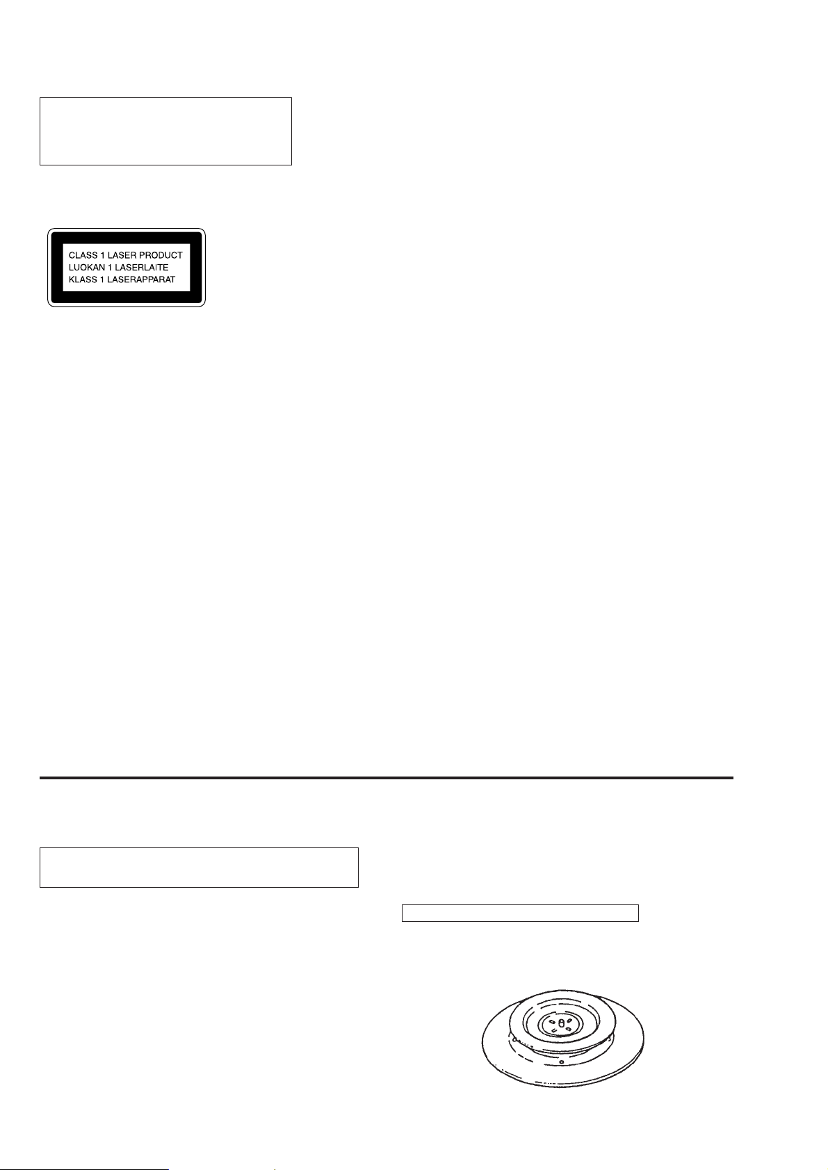
This Compact Disc player is
classified as a CLASS 1
LASER product.
The CLASS 1 LASER
PRODUCT label is located
on the bottom exterior.
Notice for customers in the United Kingdom
A moulded plug complying with BS 1363 is fitted to this
equipment for your safety and convenience.
Should the fuse in the plug supplied need to be replaced, same
rating fuse approved by ASTA or BS1 to BS 1362, (i.e. marked
with 2 or a @ mark) must be used.
SAFETY-RELATED COMPONENT WARNING!!
COMPONENTS IDENTIFIED BY MARK ! OR DOTTED LINE
WITH MARK !ON THE SCHEMATIC DIAGRAMS AND IN THE
PARTS LIST ARE CRITICAL TO SAFE OPERATION.
REPLACE THESE COMPONENTS WITH SONY PARTS WHOSE
PART NUMBERS APPEAR AS SHOWN IN THIS MANUAL OR
IN SUPPLEMENTS PUBLISHED BY SONY.
3. DISASSEMBLY
3-1. Cabinet (Front), Cabinet (Rear), SW Board ............... 5
3-2. BATT Board, Tuner Board, AC Inlet Board,
Power Board .............................................................. 5
3-3. Cabinet (Upper) .......................................................... 6
3-4. Optical pick-up Section, Mechanism deck,
Main Board, REC SW Board, CD Motor Board ....... 6
4. ADJUSTMENTS
4-1. Mechanical Adjustments ............................................ 7
4-2. Electrical Adjustments................................................ 7
5. DIAGRAMS
5-1. Explanation of IC Terminals..................................... 13
5-2. Block Diagram.......................................................... 15
5-3. Printed Wiring Boards (Former Type) ...................... 19
5-4. Schematic Diagram – Main Section (1/2) –
(Former Type) .......................................................... 23
5-5. Schematic Diagram – Main Section (2/2) –
(Former Type) .......................................................... 28
5-6. Printed Wiring Boards (New Type) .......................... 35
5-7. Schematic Diagram – Main Section (1/2) –
(New Type)............................................................... 39
5-8. Schematic Diagram – Main Section (2/2) –
(New Type)............................................................... 44
6. EXPLODED VIEWS
6-1. Front Cabinet Section ............................................... 47
6-2. Upper Cabinet Section.............................................. 48
6-3. Rear Cabinet Section ................................................ 49
6-4. Mechanism Deck Section (1) (MF-V10-117) .......... 50
6-5. Mechanism Deck Section (2) (MF-V10-117) .......... 51
6-6. Optical Pick-up Section (KSM-213CDM) ............... 52
SECTION 1
SERVICING NOTES
NOTES ON HANDLING THE OPTICAL PICK-UP
BLOCK OR BASE UNIT
The laser diode in the optical pick-up block may suffer electrostatic breakdown because of the potential difference generated
by the charged electrostatic load, etc. on clothing and the human
body.
During repair, pay attention to electrostatic breakdown and also
use the procedure in the printed matter which is included in the
repair parts.
The flexible board is easily damaged and should be handled
with care.
NOTES ON LASER DIODE EMISSION CHECK
The laser beam on this model is concentrated so as to be focused
on the disc reflective surface by the objective lens in the optical
7. ELECTRICAL PARTS LIST.................................... 53
pick-up block. Therefore, when checking the laser diode
emission, observe more than 30 cm away from the objective
lens.
CHUCK PLATE JIG ON REPAIRING
On repairing CD section, playing a disc without the CD lid, use
Chuck Plate Jig.
r
Code number of Chuck Plate Jig : X-4918-255-1
– 2 –
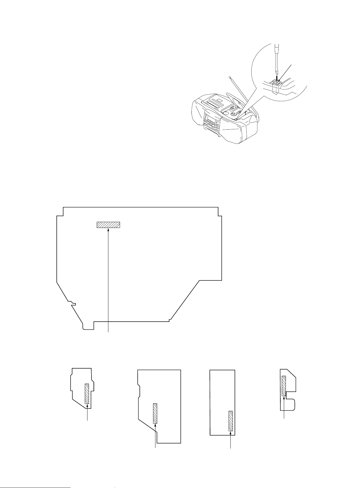
LASER DIODE AND FOCUS SEARCH OPERATION
CHECK
1. Press CD open knob.
2. Open the lid for CD.
3. Push on SWITCH (S871) as following figure.
4. Confirm the laser diode emission while observing the
objecting lens. When there is no emission, Auto Power
Control circuit or Optical Pick-up is broken.
Objective lens moves up and down once for the focus
search.
NEW TYPE INDENTIFICA TION
Printed wiring boards and schematic diagram of former type and new type are described in this Service manual.
[MAIN BOARD] (Component side)
Insert a precision
screw driver and push
SWITCH (S871)
Former Type : 1-666-263
New Type : 1-666-263
[BATT BOARD]
(Component side)
Former Type : 1-666-266
New Type : 1-666-266
-11
-12
[AC INLET BOARD]
(Component side)
-11
-12
Former Type : 1-666-267
New Type : 1-666-267
-11
-12
– 3 –
[POWER BOARD]
(Component side)
Former Type : 1-666-265
New Type : 1-666-265
Former Type : 1-666-264
New Type : 1-666-264
[REC SW BOARD]
(Component side)
-11
-12
-11
-12

LOCATION OF CONTROLS
SECTION 2
GENERAL
This section is extracted from
instruction manual.
1
246578 9!º
3
@¡
1 OPR/BATT indicator
2 POWER (or OPERATE) button
3 Tape operating buttons
4 Information display
5 SLEEP button
6 SOUND button
7 MEGA BASS button
8 VOL +/– buttons
9 OPEN/CLOSE button
!º DISPLAY/ENT/MEN button
!¡ PLAY MODE/MONO/ST/ISS button
!¡
!™!¢ !£!§!•@º !¶ !∞!ª
!™ ± button
!£ ≠ button
!¢ π button
!∞ BAND PRESET +/– buttons
!§ fl button
!¶ WAKE UP button
!• FUNCTION button
!ª HEADPHONE jack
@º STANDBY button
@¡ CLOCK button
– 4 –
SECTION 3
)
DISASSEMBLY
r
The equipment can be removed using the following procedure.
Cabinet (Front)
Set
Cabinet (Rear)
Note : Follow the disassembly procedure in the numerical order given.
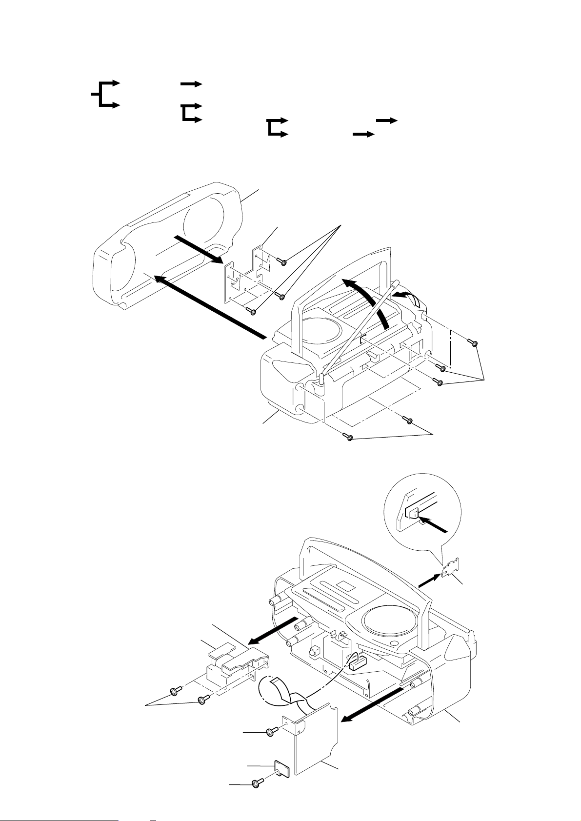
3-1. CABINET (FRONT), CABINET (REAR), SW BOARD
4
SW board
BATT board, Tuner board, AC inlet board, Power board
Cabinet (Upper)
Optical pick-up section
Mechanism deck
Cabinet (Front)
SW board
6
Main board, CD motor board
REC SW board
5
Screws +BVTP (2.6X8)
1
2
Cabinet (Rear)
3-2. BATT BOARD, TUNER BOARD, AC INLET BOARD, POWER BOARD
AC inlet board
Power board
8
3
Screws +BVTP (3X14)
1
2
BATT board
3
Screws
+BVTP (3X14
7
Screws
+BVTP (3X10)
5
Screw +BVTP (3X10)
4
Screw
+BVTP (3X10)
Tuner retainer board
3
– 5 –
6
Tuner board
Cabinet (Rear)
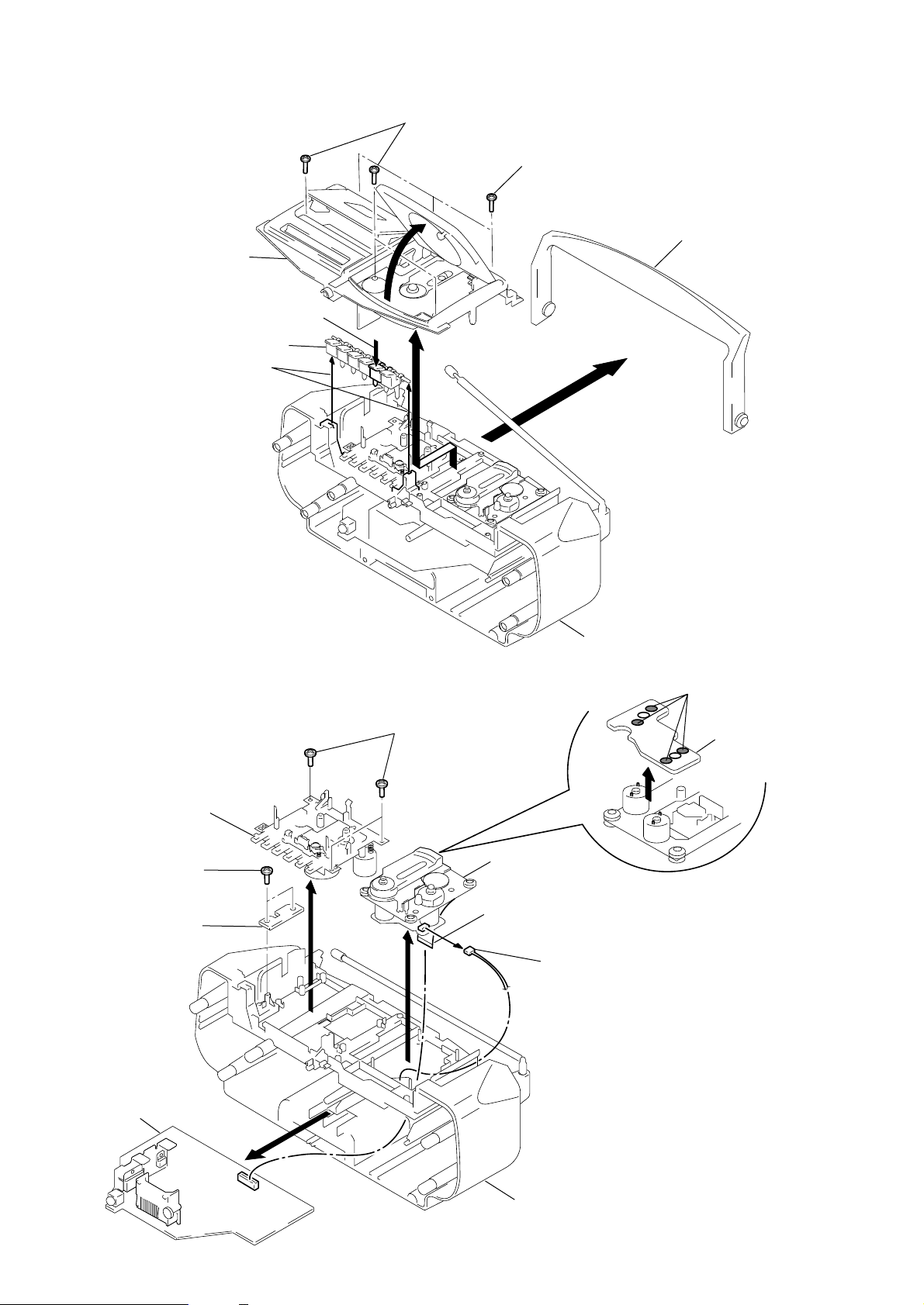
3-3. CABINET (UPPER)
4
Screws
+BVTP (3X10)
1
Screws
+BVTP (3X10)
3
Cabinet (Upper)
STOP/EJECT
2
Tape operation buttons
7
5
3-4. OPTICAL PICK-UP SECTION, MECHANISM DECK, MAIN BOARD,
REC SW BOARD, CD MOTOR BOARD
6
Cabinet (Rear)
Handle
8
Remove solder
Mechanism deck
7
Screws +BVTP (3X10)
REC SW board
Main board
4
6
5
Screws +BVTP (3X10)
1
9
Optical pick-up
section
3
Wire (Flat type) (16 core)
to MAIN board (CN701)
2
CNP707 (6pin)
CD motor board
– 6 –
Cabinet (Rear)

SECTION 4
y
ADJUSTMENTS
4-1. MECHANICAL ADJUSTMENTS
PRECAUTION
1. Clean the following parts with a denatured-alcohol-moistened
swab :
record/playback head pinch roller
erase head rubber belts
capstan
2. Demagnetize the record/playback head with a head demagne-
tizer. (Do not bring the head demagnetizer close to the erase
head.)
3. Do not use a magnetized screwdriver for the adjustments.
4. After the adjustments, apply suitable locking compound to the
parts adjusted.
5. The adjustments should be performed with the rated power sup-
ply voltage unless otherwise noted.
Torque Measurement
Torque Torque Meter Meter Reading
Forward CQ-102C
Forward
Back Tension (0.020 – 0.076 oz•inch)
Fast Forward CQ-201B
Rewind CQ-201B
T ape Tension Measurement
Torque Meter Meter Reading
CQ-403A
CQ-102C
(more than 3.53 oz)
30 – 70 g•cm
(0.42 – 0.97 oz•inch)
1.5 – 5.5 g•cm
more than 60 g•cm
(more than 0.84 oz•inch)
more than 60 g•cm
(more than 0.84 oz•inch)
more than 100g
4-2. ELECTRICAL ADJUSTMENTS
TAPE RECORDER SECTION
Standard Output Level
Output terminal HP OUT
load impedance 32Ω
output signal level 0.25V (–10dB)
Test T ape
Type Signal Used for
WS-48A 3kHz, 0dB T ape Speed Adjustment
0dB = 0.775V
Tape Speed Adjustment
Procedure :
Mode : Playback
test tape
WS-48A
(3kHz, 0dB)
set
1. Adjust the screw (T ape Speed Adjustment control inside motor)
for 2,970 – 3,030 Hz reading on the digital frequency counter.
2. Frequency difference between the beginning and the end of the
tape should be within 1.5% (45Hz).
Adjustment Location :
digital frequenc
counter
32
Ω
J301 (phones)
Tape speed adjustment
control inside motor
– 7 –
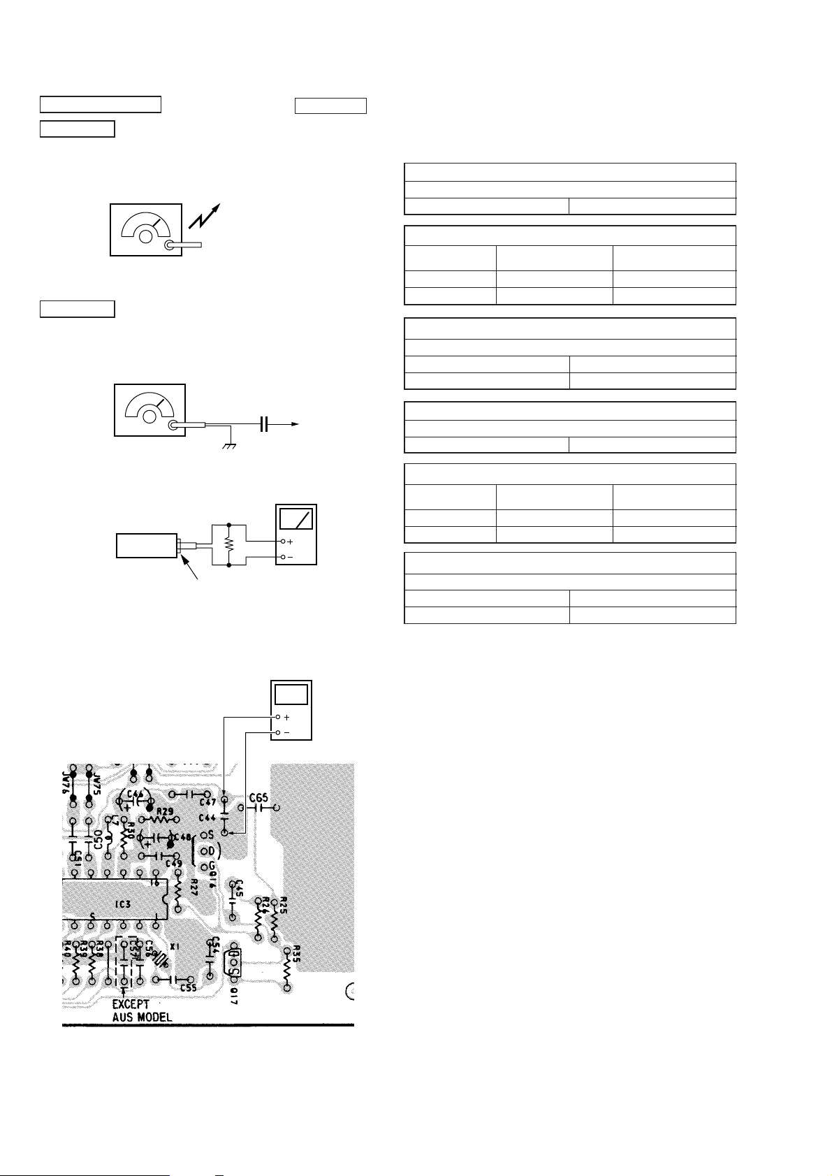
TUNER SECTION
c
r
AM Section
Function switch : AM
Volume : MIN
AM RF signal
generator
30% amplitude modulation by 400Hz
signal.
Output level : as low as possible
FM Section
Function switch : FM
Volume : MIN
FM RF signal
generator
22.5kHz frequency deviation by 400Hz signal.
Output level : as low as possible
set
Put the lead-wire
antenna close to
the set.
0.01
Ω
32
J301 (phones)
0dB = 1 µV
µ
F
telescopi
antenna
terminal
level mete
• Repeat the procedures in each adjustment several times, and the
frequency coverage and tracking adjustments should be finally
done by the trimmer capacitors.
AM IF ADJUSTMENT
Adjust for a maximum reading on level meter.
CFT1 450kHz
AM FREQUENCY COVERAGE ADJUSTMENT
Adjust part Frequency display
Confirmation 531kHz 0.8 – 1.2 V
L4 1,611kHz 4.9 – 5.3 V
AM TRACKING ADJUSTMENT
Adjust for a maximum reading on level meter.
L3 621kHz
CT2 1,404kHz
FM IF ADJUSTMENT
Adjust for a maximum reading on level meter.
T1 10.7MHz
FM FREQUENCY COVERAGE ADJUSTMENT
Adjust part Frequency display
Confirmation 87.5MHz 1.1 – 1.5 V
L2 108MHz 3.3 – 3.7 V
FM TRACKING ADJUSTMENT
Adjust for a maximum reading on level meter.
L1 87.5MHz
CT1 108MHz
reading on digital
voltmeter
reading on digital
voltmeter
Frequency Coverage Adjustment
Setting :
[TUNER BOARD]
Adjustment Location : Tuner board (See page 12)
Digital voltmeter
Adjustment Location : Tuner board (See page 12)
– 8 –
CD SECTION
TP (TO)
oscilloscope
(DC range)
TP (VC)
Note on Adjustment
1. Perform adjustment in test mode.
After adjustment, be sure to release test mode.
2. Perform adjustments in the order given.
3. Use the disc (YEDS-18. Part No. 3-702-101-01) only when so
indicated.
Before adjustment
Put the set into test mode and perform the following checks.
Repair if there are any problems.
• Sled Motor Check
1. Press fl button, then press OFF button.
2. Press ±, ≠buttons and confirm that the Optical pick-up
moves smoothly from the innermost to outermost circumference
and back smoothly and with no catching or abnormal noises.
(Cancellation of BTL mute)
± : Optical pick-up moves to the outer circumference
≠ : Optical pick-up moves to the inner circumference
• Focus Search Check
1. Press fl button. (Focus search operation is performed continu-
ously.)
2. Look at the Optical pick-up objective lens and confirm that it
moves up and down smoothly, with no catching or abnormal
noises.
3. Press π button.
Confirm that focus search operation stops. If it does not , press
π button again longer.
Note : When the malfunction is occurred by mis-passing
other buttons, turn off the power and check again
from making the test mode.
E-F Balance Adjustment
This adjustment is to be done when the optical pick-up block is
replaced.
Adjustment Procedure :
1. Connect the oscilloscope to test point TP (VC) and TP (TO) on
MAIN board.
2. Put the set into test mode.
3. optical pick-up setting to the center by ± or ≠ button
pushing.
4. Insert disc (YEDS-18) and press fl button.
5. Adjust R V703 so that the oscilloscope traveres wa veform is symmetrical, as shown in the figure below.
6. Release test mode after adjustment is completed.
VOLT / DIV : 1V
A
TIME / DIV :1ms
C
0V
B
A = B
C = 180 – 420mV
[MAIN BOARD]
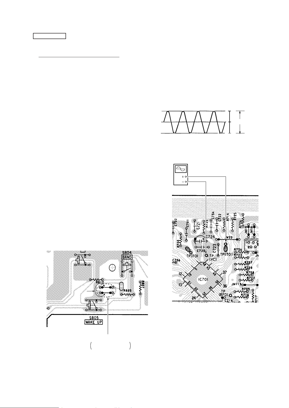
How to put the Set into Test Mode
1. Make sure the POWER switch (S801) is of f and then turn on the
power. (The LCD801 all light up.)
2. Set Test Mode by momentarily shorting both of the test mode
terminals with a jumper. (Shorting the terminals momentarily is
sufficient).
[SW BOARD]
Jamper wire
TEST mode
Open : Normal mode
Short : Test mode
Adjustment Location : Main board (See page 12)
How to Release Test Mode
1. Press the FUNCTION switch (S809).
2. Turn the POWER OFF.
– 9 –
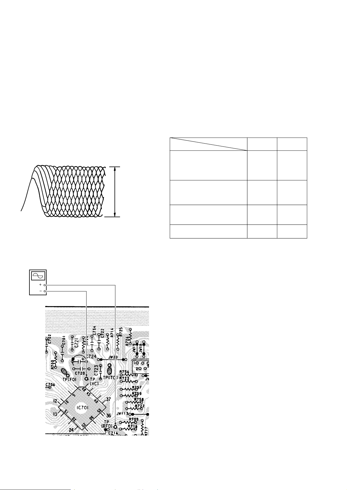
Focus Bias Adjustment
This adjustment is to be done when the optical pick-up block is
replaced.
Adjustment procedure :
1. Connect the oscilloscope to test point TP (VC) and TP (RFO) on
MAIN board.
2. Put the set into test mode.
3. Optical pick-up setting to the center by ± or ≠ button
pushing.
4. Insert disc (YEDS-18) and press fl button.
5. Press the fl button. (Tracking servo ON)
6. Adjust RV701 so that the oscilloscope waveform is as sho wn in
the figure below (eye pattern).
A good eye pattern means that the diamond shape (◊) in the center of the waveform can be clearly distinguished.
7. Release test mode after adjustment is completed.
• RF signal reference waveform (eye pattern)
VOLT/DIV : 0.2 V
TIME/DIV: 500 ns
1.0 – 1.4 V
When observing the eye pattern, set the oscilloscope for A C range
and raise vertical sensitivity.
[MAIN BOARD]
oscilloscope
(DC range)
TP (RFO)
TP (VC)
Focus/Tracking Gain Adjustment
A frequency responce analyzer is necessary in order to perform this
adjustment exactly.
Howev er, this gain has a mar gin, so e ven if it is slightly of f, there is
no problem. Therefore, do not perform this adjustment.
Focus/tracking gain determines the pick-up follow-up (vertical and
horizontal) relative to mechanical noise and mechanical shock when
the 2-axis device operate.
Howev er, as these reciprocate, the adjustment is at the point where
both are satisfied.
• When gain is raised, the noise when the 2-axis device operates
increases.
• When gain is lowered, mechanical shock and skipping occurs
more easily.
• When gain adjustment is off, the symptoms below appear.
Symptoms
r The time until music starts becomes
longer for STOP → fl button or
automatic selection.
( ≠, ± buttons pressed.)
(Normally takes about 2 seconds.)
r Music does not start and disc
continues to rotate for STOP →fl
button or automatic selection.
( ≠, ± buttons pressed.)
r Sound is interrupted during PLAY.
Or time counter display stops
progressing.
r More noise during 2-axis device
operation.
Gain
Focus Tracking
low low or high
– low
– low
high high
The following is a simple adjustment method.
– Primary Adjustment –
Note : Since exact adjustment cannot be performed, remember
the positions of the controls before performing the
adjustment.If the positions after the primary adjustment
are only a little different, return the controls to the original position.
Procedure :
1. Keep the set horizontal.
If the set is not horizontal, this adjustment cannot be performed
due to the gravity against the 2-axis device.
2. Insert disc (YEDS-18) and press fl button.
3. Connect oscilloscope to TP (FO) and TP (VC) on MAIN board.
4. Adjustment RV702 on MAIN board so that the waveform is as
shown in the figure below. (Focus gain adjustment)
Adjustment Location : Main board (See page 12)
– 10 –
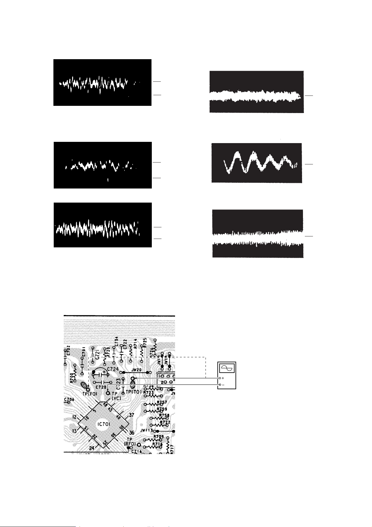
VOLT/DIV : 100mV
e
TIME/DIV : 2ms
100mV
5. Connect oscilloscope to TP (TO) and TP (VC) on MAIN board.
6. Adjust R V704 on MAIN board so that the waveform is as sho wn
in the figure below. (Tracking gain adjustment)
VOLT/DIV : 1V
TIME/DIV : 2ms
0V
• Incorrect Examples (DC level changes more than on adjusted
waveform)
VOLT/DIV : 100mV
low focus gain TIME/DIV : 2ms
200mV
0V
VOLT/DIV : 100mV
high focus gain TIME/DIV : 2ms
75mV
0V
0V
• Incorrect Examples (fundamental waveform appears)
low tracking gain
high tracking gain
High fundamental wave
( )
than for low gain
VOLT/DIV : 1V
TIME/DIV : 2ms
0V
VOLT/DIV : 1V
TIME/DIV : 2ms
0V
[MAIN BOARD]
TP (FO)
TP (TO)
TP (VC)
oscilloscop
(DC range)
– 11 –
 Loading...