

CFD-S22/S32
SERVICE MANUAL
Ver 1.0 2000. 02
Photo: CFD-S32 (Silver)
CD
Section
TC
Section
US Model
Canadian Model
E Model
Model Name Using Similar Mechanism CFD-S38
CD Mechanism Type KSM-213CDM
Optical Pick-up Name KSS-213C
Model Name Using Similar Mechanism CFD-S38
T ape T ransport Mechanism Type MF-V10-117
AUDIO POWER SPECIFICATIONS (US Model)
POWER OUTPUT AND TOTAL
HARMONIC DISTORTION
With 3.2-ohm loads, both channels driven from
150 - 6,300 Hz; rated 1.8 W per channelminimum RMS power, with no more than 10%
total harmonic distortion in AC operation.
Other Specifications
CD player section
System
Compact disc digital audio system
Laser diode properties
Material: GaAlAs
Wave length: 780 nm
Emission duration: Continuous
Laser output: Less than 44.6 µW
(This output is the value measured at a distance of
about 200 mm from the objective lens surface on
the optical pick-up block with 7 mm aperture.)
Spindle speed
200 r/min (rpm) to 500 r/min (rpm) (CLV)
Number of channels
2
Frequency response
20 - 20,000 Hz +1/–2 dB
Wow and flutter
Below measurable limit
SPECIFICATIONS
Radio section
Frequency range
FM: 87.6 - 108 MHz
AM: 530 - 1,710 kHz
Antennas
FM: Telescopic antennas
AM: Built-in ferrite bar antennas
Cassette-corder section
Recording system
4-track 2 channel stereo
Fast winding time
Approx. 120 sec. with Sony cassette C-60
Frequency response
TYPE I (normal): 70 - 10,000 Hz
General
Speaker
Full range: 10 cm (4 in.) dia.,
3.2 ohms, cone type (2)
Outputs
Headphones jack (stereo minijack)
For 16 - 68 ohms impedance headphones
– Continued on next page –
– 1 –
CD RADIO CASSETTE-CORDER

Power output (excluding US model)
2.3 W + 2.3 W (at 3.2 ohms, 10 %)
harmonic distortion in AC operation)
Power requirements
For CD radio cassette-corder:
120 V AC, 60 Hz
9 V DC, 6 size D (R20) batteries
For remote control (CFD-S32 only):
3 V DC, 2 size AA (R6) batteries
Power consumption
AC 20 W
Battery life
For CD radio cassette-corder:
FM recording
Sony R20P: approx. 13.5 h
Sony alkaline LR20: approx. 20 h
Tape playback
Sony R20P: approx. 7.5 h
Sony alkaline LR20: approx. 15 h
CD playback
Sony R20P: approx. 2.5 h
Sony alkaline LR20: approx. 7 h
Dimensions
Approx. 420 × 165 × 256 mm (w/h/d)
(16 5/8 × 6 1/2 × 10 1/8 inches) (incl. projecting parts)
Mass
Approx. 4.1 kg (9 lb. 1 oz.) (incl. batteries)
Supplied accessories
AC power cord (1)
Remote control RMT-CS32A (1) (CFD-S32 only)
Design and specifications are subject to change without
notice.
CAUTION
Use of controls or adjustments or performance of procedures other than those specified herein may result in hazardous radiation exposure.
Flexible Circuit Board Repairing
• Keep the temperature of the soldering iron around 270˚C during
repairing.
• Do not touch the soldering iron on the same conductor of the
circuit board (within 3 times).
• Be careful not to apply force on the conductor when soldering
or unsoldering.
Notes on Chip Component Replacement
• Never reuse a disconnected chip component.
• Notice that the minus side of a tantalum capacitor may be dam-
aged by heat.
NOTES ON HANDLING THE OPTICAL PICK-UP BLOCK
OR BASE UNIT
The laser diode in the optical pick-up block may suffer electrostatic
breakdown because of the potential difference generated by the
charged electrostatic load, etc. on clothing and the human body.
During repair , pay attention to electrostatic breakdown and also use
the procedure in the printed matter which is included in the repair
parts.
The flexible board is easily damaged and should be handled with
care.
NOTES ON LASER DIODE EMISSION CHECK
The laser beam on this model is concentrated so as to be focused on
the disc reflective surface by the objective lens in the optical pickup block. Therefore, when checking the laser diode emission,
observe from more than 30 cm away from the objective lens.
SAFETY-RELATED COMPONENT WARNING!!
COMPONENTS IDENTIFIED BY MARK 0 OR DOTTED LINE
WITH MARK 0 ON THE SCHEMATIC DIAGRAMS AND IN
THE PARTS LIST ARE CRITICAL TO SAFE OPERATION.
REPLACE THESE COMPONENTS WITH SONY PARTS WHOSE
P ART NUMBERS APPEAR AS SHOWN IN THIS MANUAL OR
IN SUPPLEMENTS PUBLISHED BY SONY.
ATTENTION AU COMPOSANT AYANT RAPPORT
LES COMPOSANTS IDENTIFIÉS P AR UNE MARQUE 0 SUR LES
DIAGRAMMES SCHÉMATIQUES ET LA LISTE DES PIÈCES SONT
CRITIQUES POUR LA SÉCURITÉ DE FONCTIONNEMENT. NE
REMPLACER CES COMPOSANTS QUE PAR DES PIÈCES SONY
DONT LES NUMÉROS SONT DONNÉS DANS CE MANUEL OU
DANS LES SUPPLÉMENTS PUBLIÉS PAR SONY.
À LA SÉCURITÉ!!
– 2 –
SAFETY CHECK-OUT
TABLE OF CONTENTS
After correcting the original service problem, perform the following
safety check before releasing the set to the customer:
Check the antenna terminals, metal trim, “metallized” knobs, screws,
and all other exposed metal parts for AC leakage. Check leakage as
described below.
LEAKAGE TEST
The AC leakage from any exposed metal part to earth ground and
from all exposed metal parts to any exposed metal part having a
return to chassis, must not exceed 0.5 mA (500 microamperes).
Leakage current can be measured by any one of three methods.
1. A commercial leakage tester, such as the Simpson 229 or RCA
WT-540A. Follow the manufacturers’ instructions to use these
instruments.
2. A battery-operated AC milliammeter. The Data Precision 245
digital multimeter is suitable for this job.
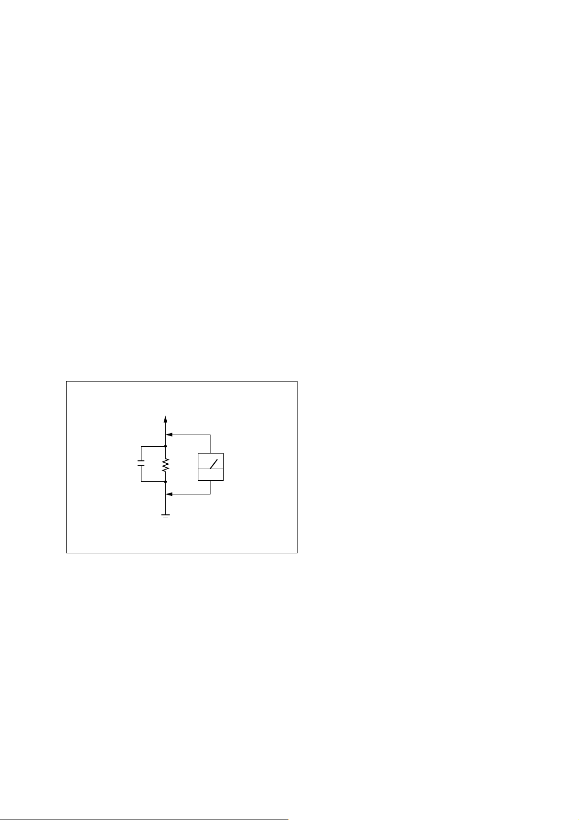
3. Measuring the voltage drop across a resistor by means of a VOM
or battery-operated AC voltmeter. The “limit” indication is 0.75
V, so analog meters must have an accurate low-voltage scale. The
Simpson 250 and Sanwa SH-63Trd are examples of a passive
VOM that is suitable. Nearly all battery operated digital
multimeters that have a 2V AC range are suitable. (See Fig. A)
To Exposed Metal
Parts on Set
0.15µF
Ω
1.5k
Earth Ground
AC
voltmeter
(0.75V)
Fig. A. Using an AC voltmeter to check AC leakage.
1. SERVICING NOTES......................................................... 4
2. GENERAL
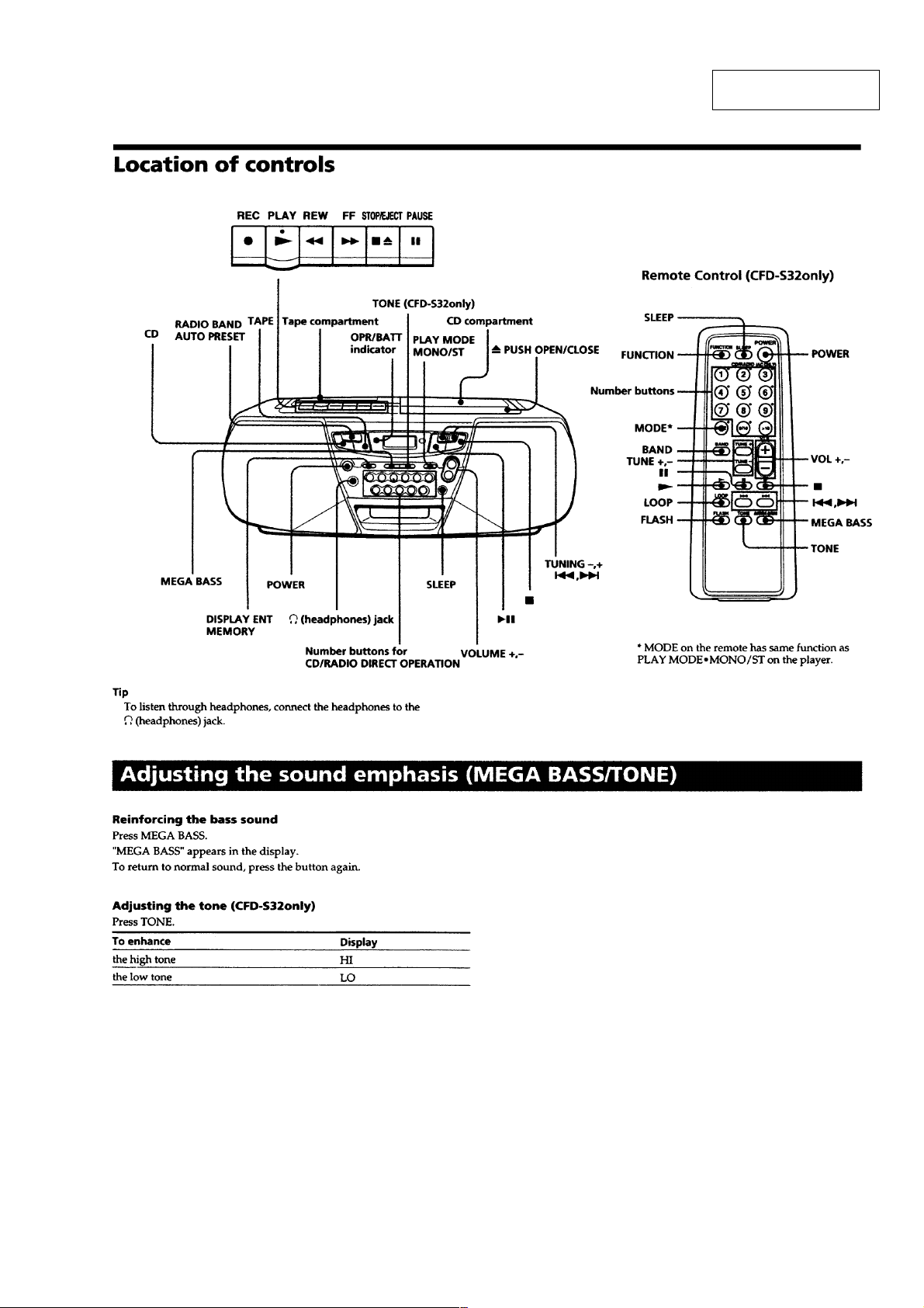
Location of controls................................................................. 5
Adjusting the sound emphasis (MEGA BASS/TONE)........... 5
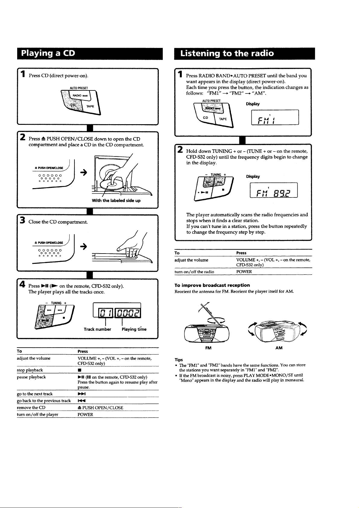
Playing a CD ........................................................................... 6
Listening to the radio ............................................................... 6
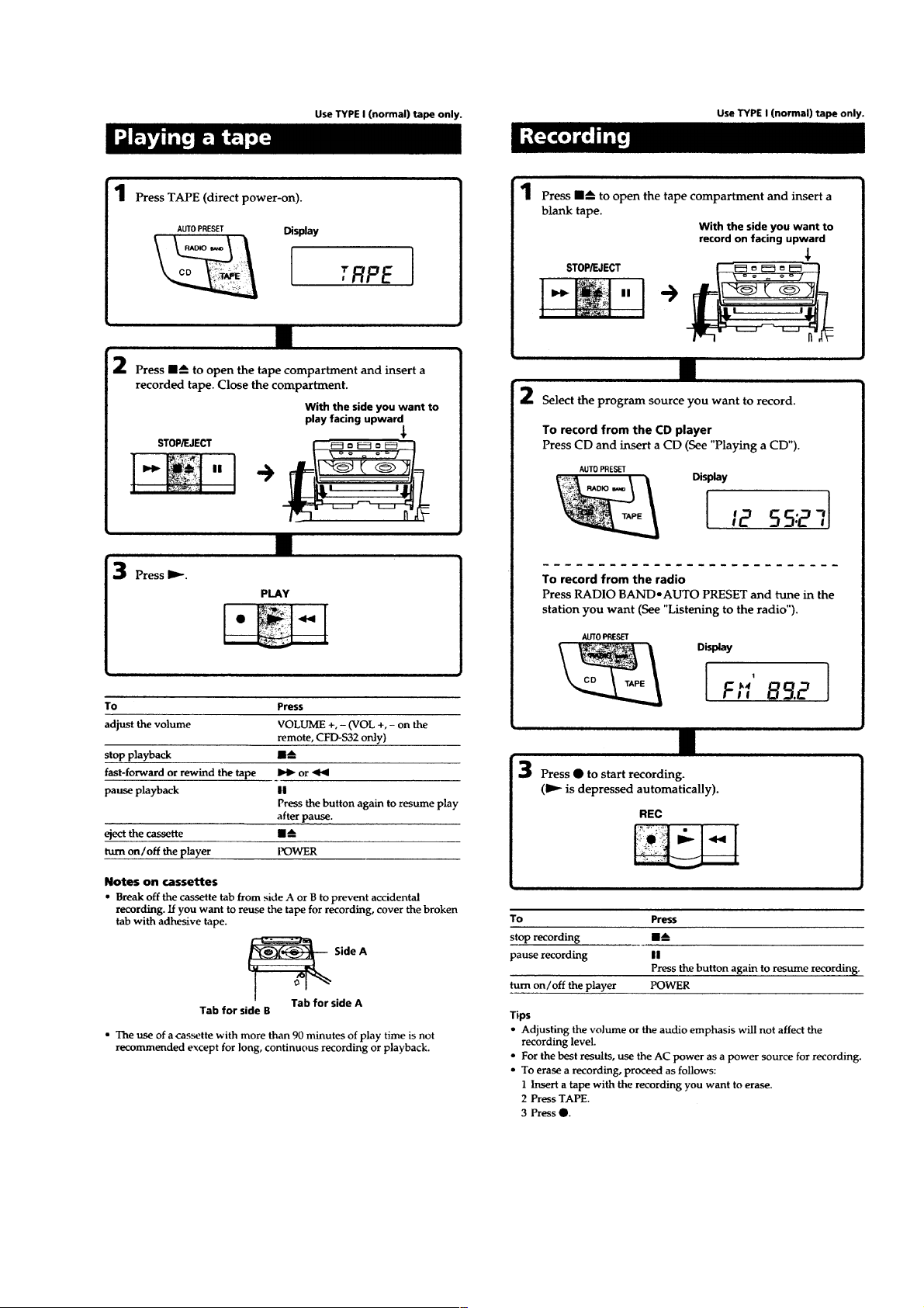
Playing a tape .......................................................................... 7
Recording ................................................................................ 7
3. DISASSEMBLY
3-1. Cabinet (Front) Sub Assy .................................................... 8
3-2. Wires ................................................................................... 9
3-3. Secondary Board, Power Board .......................................... 9
3-4. Tuner Board.......................................................................10
3-5. Cabinet (Upper) Block Assy ............................................. 10
3-6. Main Board ....................................................................... 11
3-7. CD Mechanism Block ....................................................... 11
3-8. Tape Mechanism Block ..................................................... 12
3-9. Holder Assy, Cassette........................................................ 12
3-10. TC Board ........................................................................... 13
4. MECHANICAL ADJUSTMENTS............................... 14
5. ELECTRICAL ADJUSTMENTS
Tape Section .......................................................................... 14
Tuner Section......................................................................... 15
CD Section ............................................................................ 16
6. DIAGRAMS
6-1. IC Pin Description............................................................. 17
6-2. Circuit Boards Location .................................................... 18
6-3. Block Diagram – CD Section –......................................... 19
6-4. Block Diagram – Main Section –...................................... 21
6-5. Printed W iring Board – Tuner Section – ........................... 23
6-6. Schematic Diagram – Tuner Section – .............................. 25
6-7. Printed Wiring Board – CD Section – ............................... 27
6-8. Schematic Diagram – CD Section –.................................. 29
6-9. Schematic Diagram – TC Section – .................................. 31
6-10. Printed Wiring Boards – Main Section – .......................... 33
6-11. Schematic Diagram – Main Section (1/2) –...................... 35
6-12. Schematic Diagram – Main Section (2/2) –...................... 37
6-13. Printed Wiring Board – Control Section – ........................ 39
6-14. Schematic Diagram – Control Section – ........................... 41
6-15. Printed W iring Boards – Power Supply Section – ............ 43
6-16. Schematic Diagram – Power Supply Section –................. 45
7. EXPLODED VIEWS
7-1. Cabinet (Front) Section ..................................................... 50
7-2. Cabinet (Rear) Section ...................................................... 51
7-3. Cabinet (Upper) Section.................................................... 52
7-4. Tape Mechanism Section-1 ...............................................53
7-5. Tape Mechanism Section-2 ...............................................54
7-6. Optical Pick-up Section .................................................... 55
8. ELECTRICAL PARTS LIST......................................... 56
– 3 –
SECTION 1
SERVICING NOTES
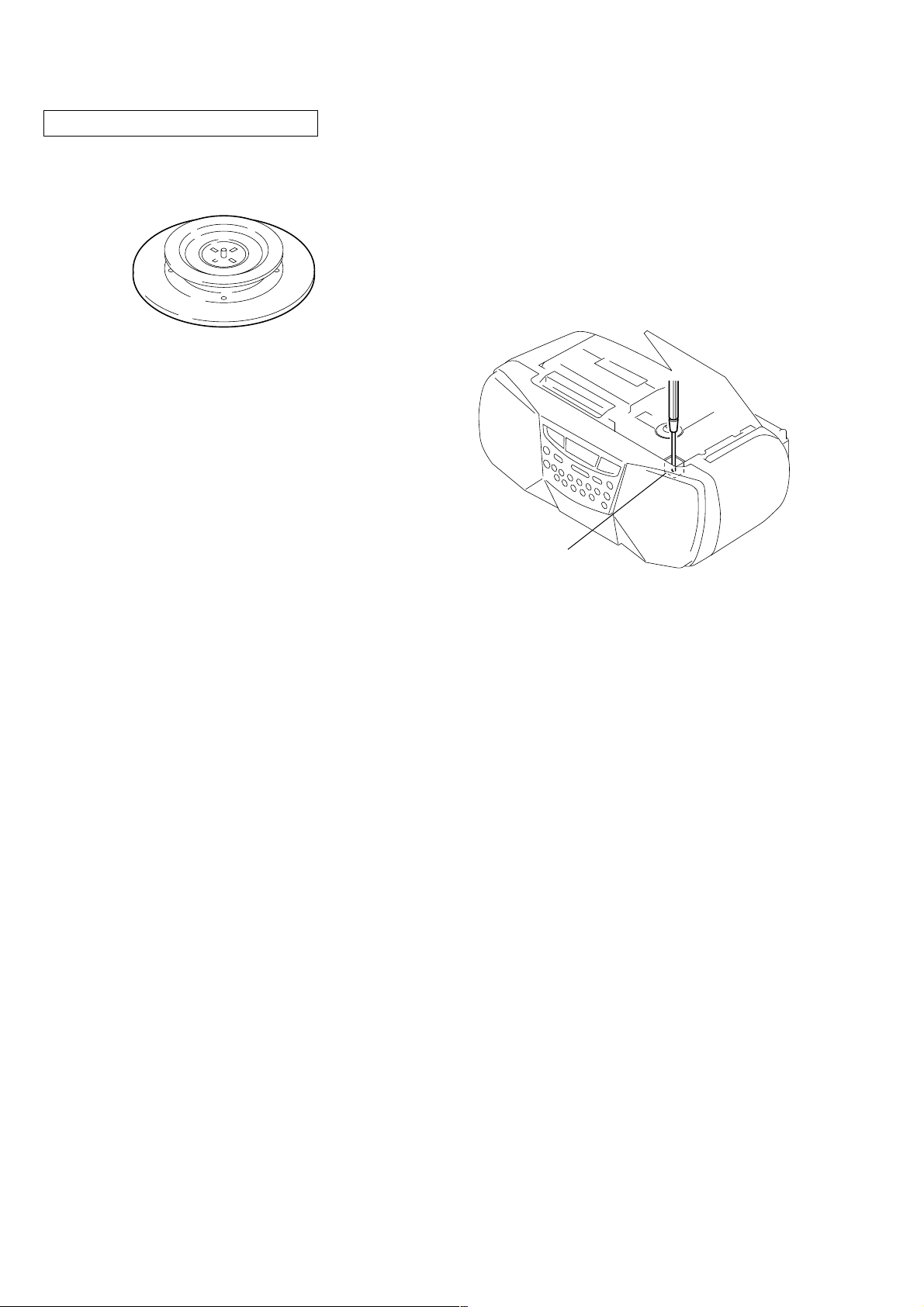
CHUCK PLATE JIG ON REPAIRING
On repairing CD section, playing a disc without the lid (CD), use
Chuck Plate Jig.
• Code number of Chuck Plate Jig: X-4918-255-1
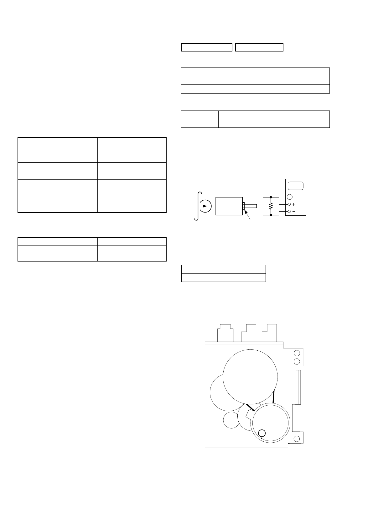
LASER DIODE AND FOCUS SEARCH OPERATION
CHECK
1. Turn ON the POWER button and press FUNCTION button to
CD position.
2. Open the lid (CD).
3. Turn on S501 with screwdriver, etc. as following figure.
4. Press the CD N X button.
5. Confirm the laser diode emission while observing the objecting
lens. When there is no emission, Auto Power Control circuit or
Optical Pick-up is broken.
Objective lens moves up and down three times for focus search.
S501
– 4 –
SECTION 2
GENERAL
This section is extracted
from instruction manual.
– 5 –
– 6 –
– 7 –
SECTION 3
DISASSEMBLY
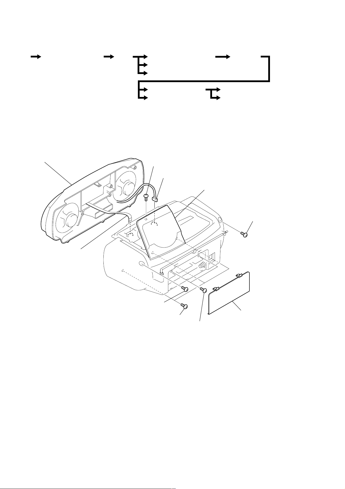
• The equipment can be removed using the following procedure.
Set Cabinet (Front) Sub Assy Wires
Note : Follow the disassembly procedure in the numerical order given.
Cabinet (Upper) Block Assy
Secondary, Power Board
Tuner Board
Tape Mechanism Block
CD Mechanism Block
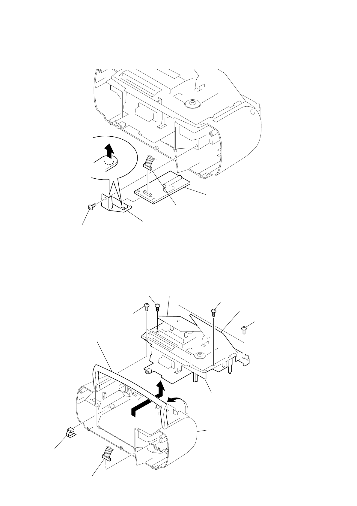
3-1. CABINET (FRONT) SUB ASSY
9 cabinet (front) sub assy
6 BVTP 3x12
7 CNP323
Main Board
Holder Assy, Cassette
TC Board
lid (CD)
2 BVTP 3x10
8 CNP501
5 BVTP 3x10
1 lid, battery case
4 BVTP 3x12
3 BVTP 3x10
– 8 –
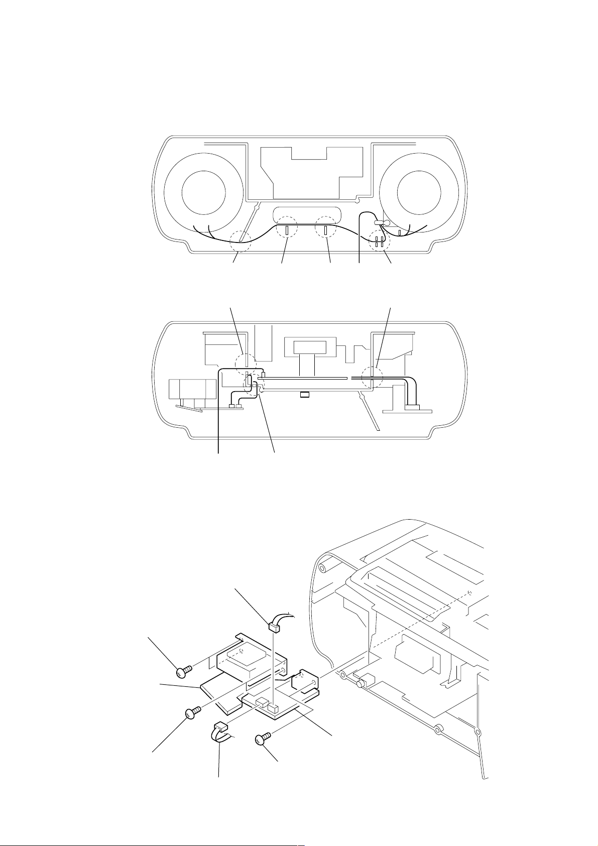
3-2. WIRES
)
Put flat cable and wires between the cabinets and push them in the
grooves located at A to G in the figure to prevent disconnection
before assembling the set.
CABINET (FRONT
AB
E
from speaker
3-3. SECONDARY BOARD, POWER BOARD
CD
G
CABINET (REAR)
F
3 BVTP 3x10
SECONDARY board
2 BVTP 3x10
5 CNP901
6 POWER board
1 BVTP 3x10
4 CNP902
– 9 –
3-4. TUNER BOARD
4
5 TUNER board
1 CNP1
2 BVTP 3x10
3-5. CABINET (UPPER) BLOCK ASSY
5 BVTP 3x10
9 handle
3 holder (PWB)(TU)
6 BVTP 3x12
3 holder assy, cassette
7 BVTP 3x12
4 lid (CD)
8 BVTP 3x12
0 cabinet (upper) block assy
2 CNP902
cabinet (rear)
1 CNP1
– 10 –
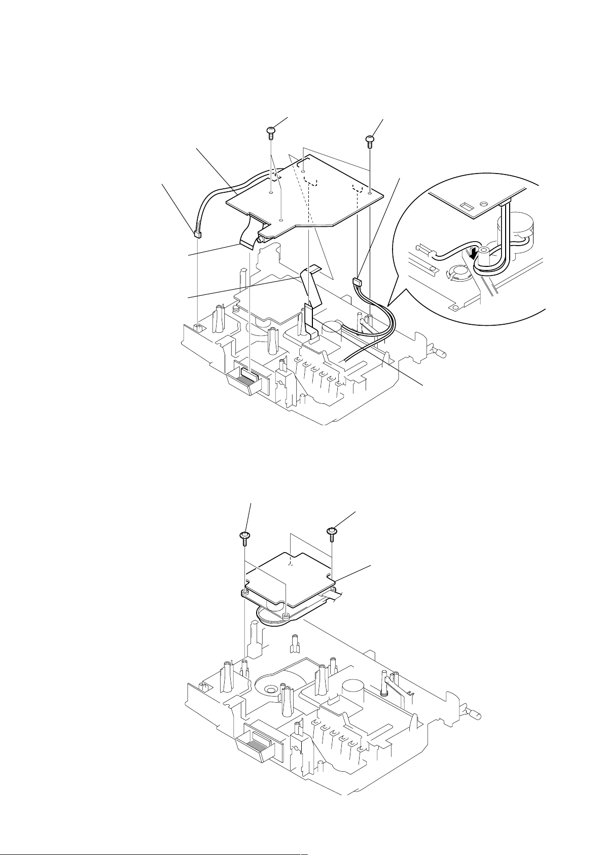
3-6. MAIN BOARD
3 connector
4 CNP651
7 CNP502
8 MAIN board
2 BVTP 3x10
1 BVTP 3x10
5 CNP322
6 CNP505
3-7. CD MECHANISM BLOCK
1 PWH 2.6x10
2 PWH 2.6x10
3 CD mechanism block
– 11 –
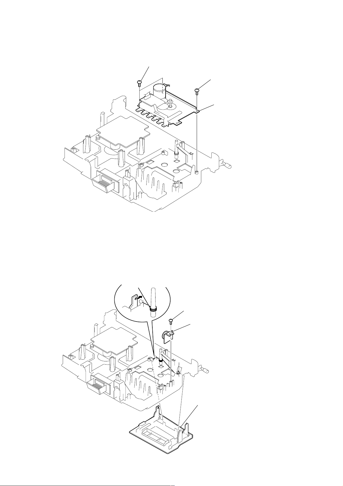
3-8. TAPE MECHANISM BLOCK
k
1 BVTP 3x10
2 BVTP 3x10
3 tape mechanism bloc
3-9. HOLDER ASSY, CASSETTE
3
1 BVTP 3x10
2 DAMPER
4 holder assy, cassette
– 12 –
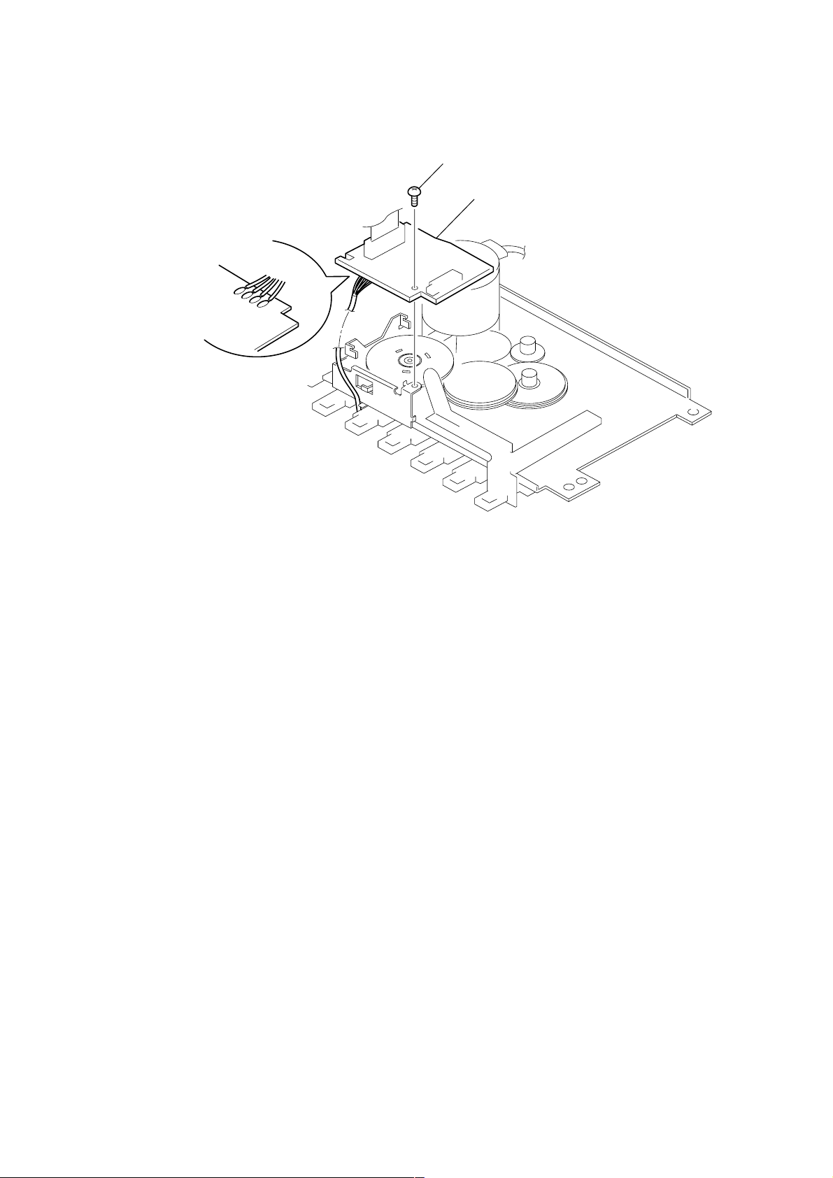
3-10. TC BOARD
3 Removal the solders.
1 BVTP 2x4
2 TC board
– 13 –
SECTION 4
MECHANICAL ADJUSTMENTS
SECTION 5
ELECTRICAL ADJUSTMENTS
PRECAUTION
1. Clean the following parts with a denatured-alcohol-moistened
swab :
record/playback head pinch roller
erase head rubber belts
capstan idlers
2. Demagnetize the record/playback head with a head demagnetizer. (Do not bring the head magnetizer close to the erase head.)
3. Do not use a magnetized screwdriver for the adjustments.
4. The adjustments should be performed with the rated power
supply voltage unless otherwise noted.
Torque Measurement
Mode Torque meter Meter reading
FWD CQ-102C
FWD
Back Tension (0.021 – 0.076 oz • inch)
FF CQ-201B
REW CQ-201B
Tape T ension Measurement
Mode Tension meter Meter Reading
FWD CQ-403A
CQ-102C
30 – 70 g • cm
(0.42 – 0.97 oz • inch)
1.5 – 5.5 g • cm
more than 60 g • cm
(more than 0.83 oz • inch)
more than 60 g • cm
(more than 0.83 oz • inch)
more than 100 g
(more than 3.53 oz)
TAPE SECTION 0 dB = 0.775 V
• Standard Output Level
Output terminal HP OUT
load impedance 32 Ω
output signal level 0.25 V (–10 dB)
• Test Tape
Type Signal Used for
WS-48A 3 kHz, 0 dB tape speed adjustment
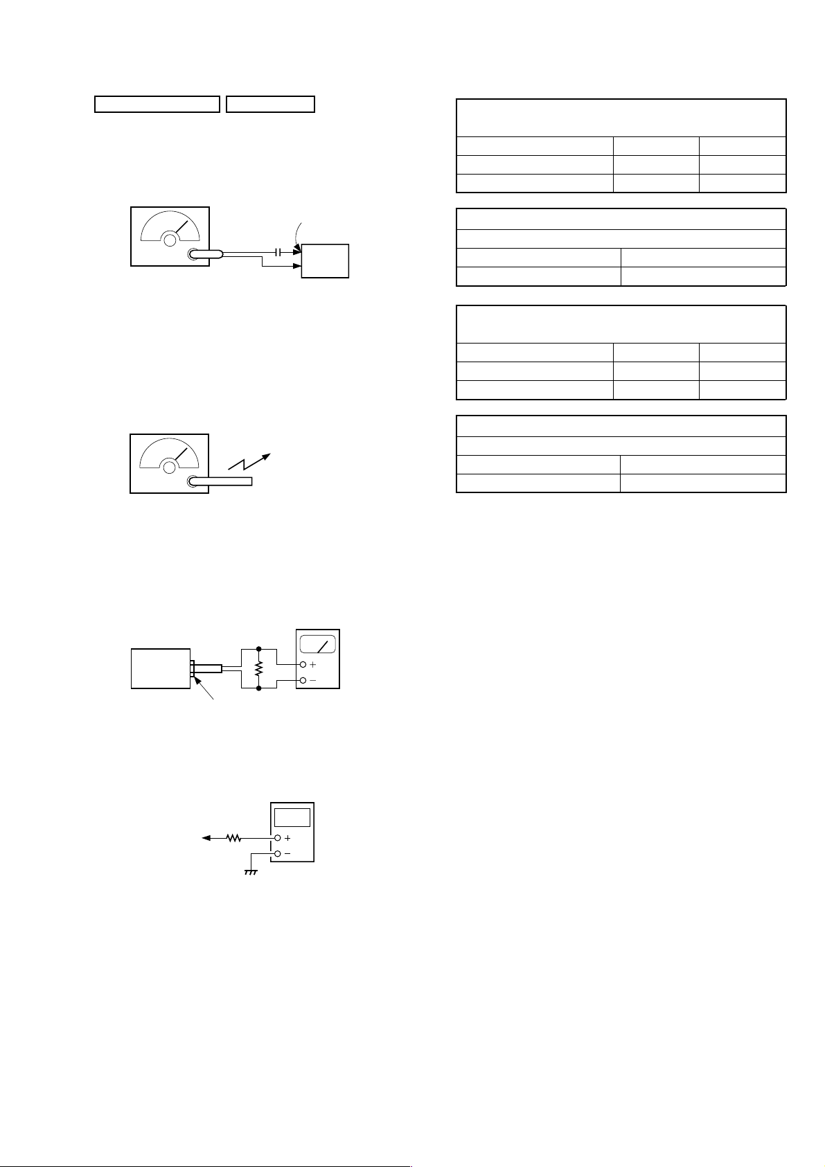
Tape Speed Adjustment
Procedure:
Mode: playback
test tape
WS-48A
(3 kHz, 0 dB)
set
Phones jack
Adjust so that the value on the digital frequency counter is
3,000 Hz.
Specification Value:
Digital frequency counter
2,910 to 3,090 Hz
digital frequency
counter
32 Ω
Adjust so that the frequency at the beginning and that at the end of
tape winding are between 2,910 to 3,090 Hz.
Adjustment Location:
Tape speed adjustment
control inside motor
– 14 –
)
TUNER SECTION 0 dB = 1 µV
• FM Section
Setting:
RADIO (BAND) button: FM
FM RF signal
generator
0.01 µF
75 kHz frequency
deviation by 1 kHz signal
output level : as low as possible
• AM Section
Setting:
RADIO (BAND) button: AM
AM RF signal
generator
Put the lead-wire
antenna close to
the set.
30% amplitude
modulation by
400 Hz signal
TP (JW2)
set
FM FREQUENCY COVERAGE
ADJUSTMENT
Frequency Display 87.5 MHz 108 MHz
Reading on Digital voltmeter 1.6 ± 0.4 V 4.0 ± 0.3V
Adjustment Part <confirmation> L2
FM TRACKING ADJUSTMENT
Adjust for a maximum reading on level meter.
L1 CT1
87.5 MHz 108 MHz
AM FREQUENCY COVERAGE
ADJUSTMENT
Frequency Display 530 kHz 1,710 kHz
Reading on Digital voltmeter 1.1 ± 0.1 V 5.2 ± 0.8V
Adjustment Part L4 <confirmation>
AM TRACKING ADJUSTMENT
Adjust for a maximum reading on level meter.
L3 CT3
620 kHz 1,400 kHz
• For AM adjustment, fix the ferrite-rod antenna (L3) as shown
below and then perform tracking adjustment at L4 and CT3.
Lastly check the voltage.
• Connecting Level Meter (FM and AM)
level meter
(range: 0.5–5 V ac
32 Ω
set
i jack (J321)
• Connecting Digital Voltmeter (FM and AM)
digital
voltmeter
100 kΩ
TP (VT)
• Repeat the procedures in each adjustment several times, and the
frequency coverage and tracking adjustments should be finally
done by the trimmer capacitors.
– 15 –
 Loading...