

Sony CFDS-22, CFDS-32 Service manual
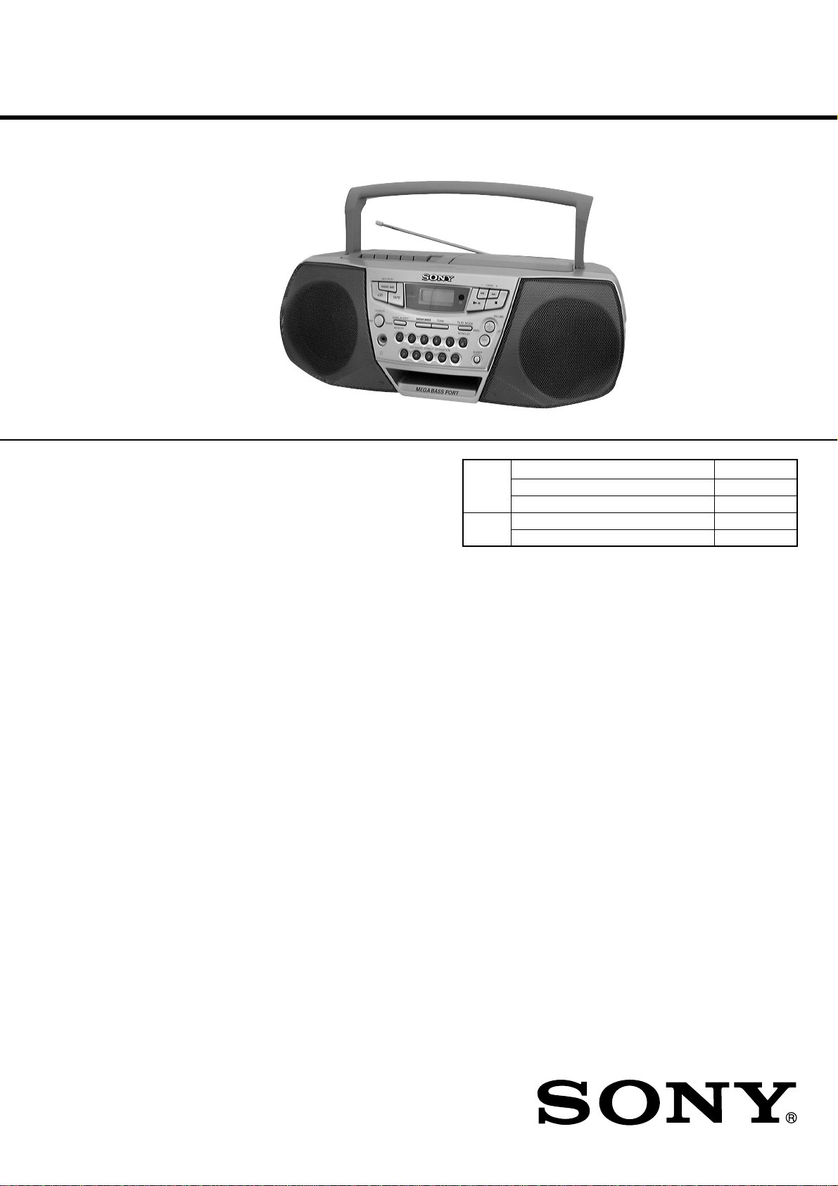
CFD-S22/S32
SERVICE MANUAL
Ver 1.2 2000. 07
With SUPPLEMENT
(9-927-674-81)
Photo: CFD-S32 (Silver)
CD
Section
TC
Section
US Model
Canadian Model
E Model
Australian Model
Model Name Using Similar Mechanism CFD-S38
CD Mechanism Type KSM-213CDM
Optical Pick-up Name KSS-213C
Model Name Using Similar Mechanism CFD-S38
T ape T ransport Mechanism Type MF-S22-117
AUDIO POWER SPECIFICATIONS (US Model)
POWER OUTPUT AND TOTAL
HARMONIC DISTORTION
With 3.2-ohm loads, both channels driven from
150 - 6,300 Hz; rated 1.8 W per channelminimum RMS power, with no more than 10%
total harmonic distortion in AC operation.
Other Specifications
CD player section
System
Compact disc digital audio system
Laser diode properties
Material: GaAlAs
Wave length: 780 nm
Emission duration: Continuous
Laser output: Less than 44.6 µW
(This output is the value measured at a distance of
about 200 mm from the objective lens surface on
the optical pick-up block with 7 mm aperture.)
Spindle speed
200 r/min (rpm) to 500 r/min (rpm) (CLV)
Number of channels
2
Frequency response
20 - 20,000 Hz +1/–2 dB
Wow and flutter
Below measurable limit
SPECIFICATIONS
Radio section
Frequency range
US, CND, E92, MX model:
FM: 87.6 - 108 MHz
AM: 530 - 1,710 kHz
SP, AR, AUS, E4 model:
FM: 87.5 - 108 MHz or 87.6 - 108 MHz
AM: 531 - 1,602 kHz
Antennas
FM: Telescopic antennas
AM: Built-in ferrite bar antennas
Cassette-corder section
Recording system
4-track 2 channel stereo
Fast winding time
Approx. 120 sec. with Sony cassette C-60
Frequency response
TYPE I (normal): 70 - 10,000 Hz
General
Speaker
Full range: 10 cm (4 in.) dia.,
3.2 ohms, cone type (2)
Outputs
Headphones jack (stereo minijack)
For 16 - 68 ohms impedance headphones
– Continued on next page –
– 1 –
CD RADIO CASSETTE-CORDER

Power output (excluding US model)
2.3 W + 2.3 W (at 3.2 ohms, 10 %)
harmonic distortion in AC operation)
Power requirements
For CD radio cassette-corder:
US, CND, E92, MX model:
120 V AC, 60 Hz
SP, AR, AUS model:
230 V AC, 50 Hz
E4 model:
110 - 120 V/220 - 240 V AC, 50/60 Hz
9 V DC, 6 size D (R20) batteries
For remote control (CFD-S32 only):
3 V DC, 2 size AA (R6) batteries
Power consumption
AC 20 W
Battery life
For CD radio cassette-corder:
FM recording
Sony R20P: approx. 13.5 h
Sony alkaline LR20: approx. 20 h
Tape playback
Sony R20P: approx. 7.5 h
Sony alkaline LR20: approx. 15 h
CD playback
Sony R20P: approx. 2.5 h
Sony alkaline LR20: approx. 7 h
Dimensions
Approx. 420 × 165 × 256 mm (w/h/d)
5/8 × 6 1/2 × 10 1/8 inches) (incl. projecting parts)
(16
Mass
Approx. 4.1 kg (9 lb. 1 oz.) (incl. batteries)
Supplied accessories
AC power cord (1)
Remote control RMT-CS32A (1) (CFD-S32 only)
Design and specifications are subject to change without
notice.
• Abbreviation
AR : Argentina model
AUS : Australian model
CND : Canadian model
E4 : AC 110-120V/220-240V area in E model
E92 : AC 120V area in E model
MX : Mexican model
SP : Singapore model
CAUTION
Use of controls or adjustments or performance of procedures other than those specified herein may result in hazardous radiation exposure.
Flexible Circuit Board Repairing
• Keep the temperature of the soldering iron around 270˚C during
repairing.
• Do not touch the soldering iron on the same conductor of the
circuit board (within 3 times).
• Be careful not to apply force on the conductor when soldering
or unsoldering.
Notes on Chip Component Replacement
• Never reuse a disconnected chip component.
• Notice that the minus side of a tantalum capacitor may be dam-
aged by heat.
NOTES ON HANDLING THE OPTICAL PICK-UP BLOCK
OR BASE UNIT
The laser diode in the optical pick-up block may suffer electrostatic
breakdown because of the potential difference generated by the
charged electrostatic load, etc. on clothing and the human body.
During repair, pay attention to electrostatic breakdown and also use
the procedure in the printed matter which is included in the repair
parts.
The flexible board is easily damaged and should be handled with
care.
NOTES ON LASER DIODE EMISSION CHECK
The laser beam on this model is concentrated so as to be focused on
the disc reflective surface by the objective lens in the optical pickup block. Therefore, when checking the laser diode emission,
observe from more than 30 cm away from the objective lens.
SAFETY-RELATED COMPONENT WARNING!!
COMPONENTS IDENTIFIED BY MARK 0 OR DOTTED LINE
WITH MARK 0 ON THE SCHEMATIC DIAGRAMS AND IN
THE PARTS LIST ARE CRITICAL TO SAFE OPERATION.
REPLACE THESE COMPONENTS WITH SONY PARTS WHOSE
P ART NUMBERS APPEAR AS SHOWN IN THIS MANUAL OR
IN SUPPLEMENTS PUBLISHED BY SONY.
ATTENTION AU COMPOSANT AYANT RAPPOR T
À LA SÉCURITÉ!!
LES COMPOSANTS IDENTIFIÉS P AR UNE MARQUE 0 SUR LES
DIAGRAMMES SCHÉMA TIQUES ET LA LISTE DES PIÈCES SONT
CRITIQUES POUR LA SÉCURITÉ DE FONCTIONNEMENT. NE
REMPLACER CES COMPOSANTS QUE PAR DES PIÈCES SONY
DONT LES NUMÉROS SONT DONNÉS DANS CE MANUEL OU
DANS LES SUPPLÉMENTS PUBLIÉS PAR SONY.
– 2 –
SAFETY CHECK-OUT
TABLE OF CONTENTS
After correcting the original service problem, perform the following
safety check before releasing the set to the customer:
Check the antenna terminals, metal trim, “metallized” knobs, screws,
and all other exposed metal parts for A C leakage. Check leakage as
described below.
LEAKAGE TEST
The AC leakage from any exposed metal part to earth ground and
from all exposed metal parts to any exposed metal part having a
return to chassis, must not exceed 0.5 mA (500 microamperes).
Leakage current can be measured by any one of three methods.
1. A commercial leakage tester, such as the Simpson 229 or RCA
WT-540A. Follow the manufacturers’ instructions to use these
instruments.
2. A battery-operated AC milliammeter. The Data Precision 245
digital multimeter is suitable for this job.
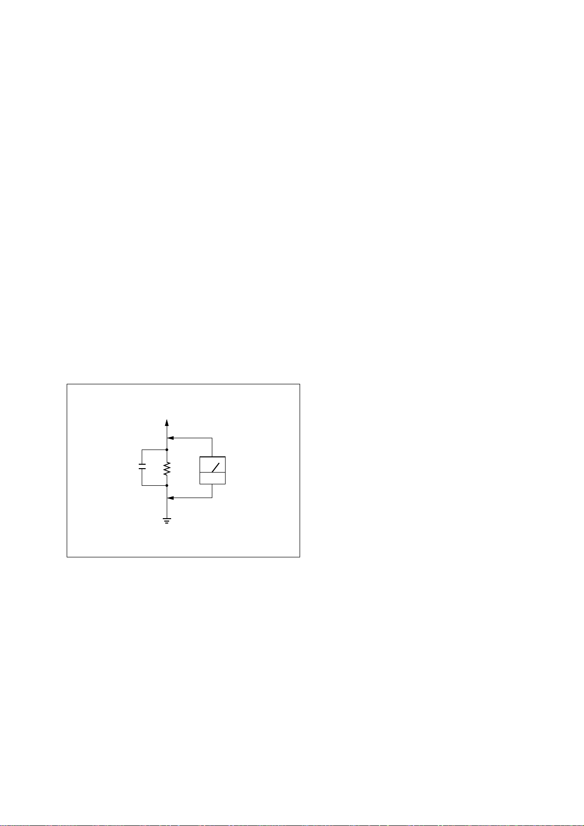
3. Measuring the voltage drop across a resistor by means of a V OM
or battery-operated A C v oltmeter. The “limit” indication is 0.75
V, so analog meters must have an accurate low-voltage scale. The
Simpson 250 and Sanwa SH-63Trd are examples of a passive
VOM that is suitable. Nearly all battery operated digital
multimeters that have a 2V AC range are suitable. (See Fig. A)
To Exposed Metal
Parts on Set
0.15µF
1.5k
Ω
Earth Ground
AC
voltmeter
(0.75V)
Fig. A. Using an AC voltmeter to check AC leakage.
1. SERVICING NOTES......................................................... 4
2. GENERAL
Location of controls................................................................. 5
Adjusting the sound emphasis (MEGA BASS/TONE)........... 5
Playing a CD ........................................................................... 6
Listening to the radio............................................................... 6
Playing a tape .......................................................................... 7
Recording ................................................................................ 7
3. DISASSEMBLY
3-1. Cabinet (Front) Sub Assy....................................................8
3-2. Wires ................................................................................... 9
3-3. Secondary Board, Power Board .......................................... 9
3-4. VOL SEL Board ................................................................ 10
3-5. Tuner Board....................................................................... 10
3-6. Cabinet (Upper) Assy........................................................ 11
3-7. Main Board ....................................................................... 11
3-8. CD Mechanism Block ....................................................... 12
3-9. Tape Mechanism Block ..................................................... 12
3-10. Holder Assy, Cassette ........................................................ 13
3-11. PRE Board......................................................................... 13
4. MECHANICAL ADJUSTMENTS............................... 14
5. ELECTRICAL ADJUSTMENTS
Tape Section .......................................................................... 14
Tuner Section......................................................................... 15
CD Section ............................................................................ 16
6. DIAGRAMS
6-1. IC Pin Description.............................................................17
6-2. Circuit Boards Location .................................................... 18
6-3. Block Diagram – CD Section –......................................... 19
6-4. Block Diagram – Main Section –......................................21
6-5. Printed Wiring Board – Tuner Section –...........................23
6-6. Schematic Diagram – Tuner Section –.............................. 25
6-7. Printed Wiring Board – CD Section –...............................27
6-8. Schematic Diagram – CD Section –.................................. 29
6-9. Schematic Diagram – PRE Section –................................31
6-10. Printed Wiring Boards – Main Section – .......................... 33
6-11. Schematic Diagram – Main Section (1/2) – ...................... 35
6-12. Schematic Diagram – Main Section (2/2) – ...................... 37
6-13. Printed Wiring Board – Control Section – ........................ 39
6-14. Schematic Diagram – Control Section – ........................... 41
6-15. Printed Wiring Boards – Power Supply Section – ............43
6-16. Schematic Diagram – Power Supply Section –................. 45
7. EXPLODED VIEWS
7-1. Cabinet (Front) Section ..................................................... 50
7-2. Cabinet (Rear) Section ...................................................... 51
7-3. Cabinet (Upper) Section.................................................... 52
7-4. Tape Mechanism Section-1 ............................................... 54
7-5. Tape Mechanism Section-2 ............................................... 55
7-6. Optical Pick-up Section .................................................... 56
8. ELECTRICAL PARTS LIST......................................... 57
– 3 –
SECTION 1
SERVICING NOTES
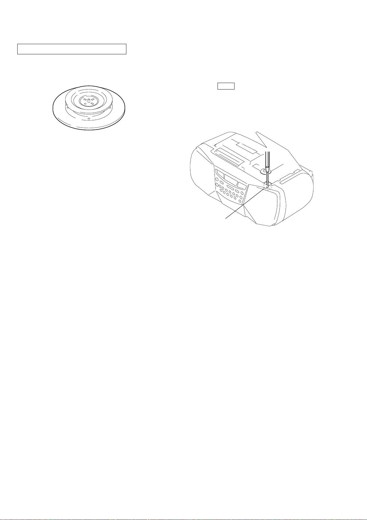
CHUCK PLATE JIG ON REPAIRING
On repairing CD section, playing a disc without the lid (CD), use
Chuck Plate Jig.
• Code number of Chuck Plate Jig: X-4918-255-1
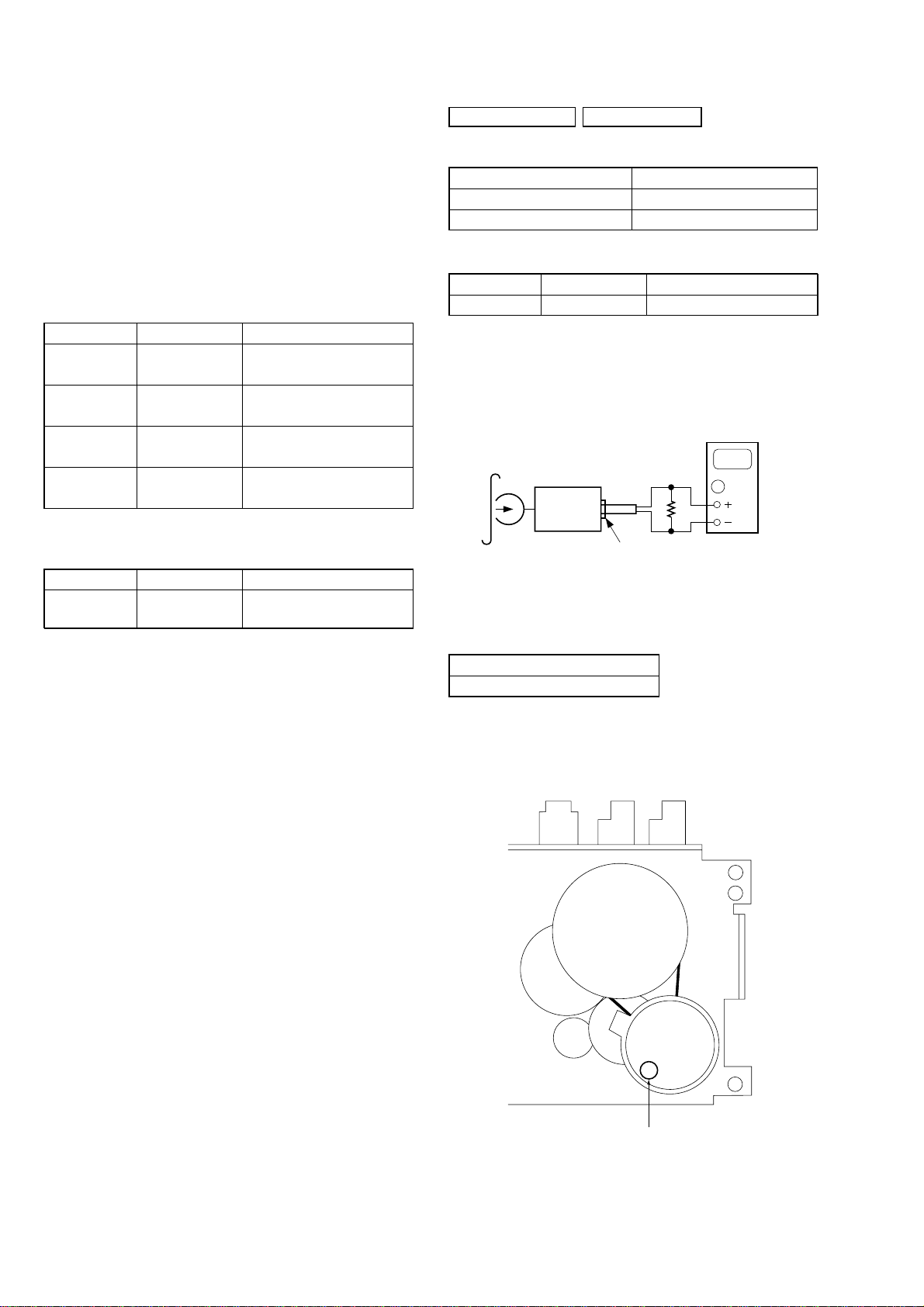
LASER DIODE AND FOCUS SEARCH OPERATION
CHECK
1. Turn ON the POWER button and press FUNCTION button to
CD position.
2. Open the lid (CD).
3. Turn on S501 with screwdriver, etc. as following figure.
4. Press the CD N X button.
5. Confirm the laser diode emission while observing the objecting
lens. When there is no emission, Auto P ower Control circuit or
Optical Pick-up is broken.
Objective lens moves up and down three times for focus search.
S501
– 4 –
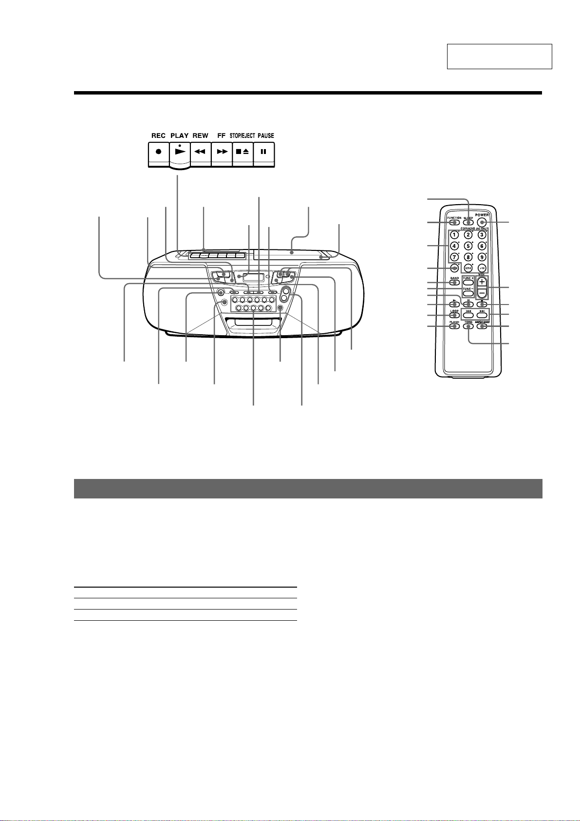
Reinforcing the bass sound
Press MEGA BASS.
"MEGA BASS" appears in the display.
To return to normal sound, press the button again.
Adjusting the tone (CFD-S32only)
Press TONE.
To enhance
the high tone
the low tone
Tape compartment
MEGA BASS
Z PUSH OPEN/CLOSE
CD compartment
VOLUME +,–
TUNING –,+
DISPLAY ENT
MEMORY
PLAY MODE
MONO/ST
TONE
Location of controls
Adjusting the sound emphasis (MEGA BASS/TONE)
i (headphones) jack
Number buttons for
CD/RADIO DIRECT OPERATION
x
BX
.,>
POWER
SLEEP
CD
TAPE
RADIO BAND
AUTO PRESET
Display
HI
LO
Tip
To listen through headphones, connect the headphones to the
i (headphones) jack.
POWER
SLEEP
FUNCTION
Number buttons
MODE*
BAND
TUNE +,–
VOL +,–
x
X
N
.,>LOOP
FLASH
TONE (CFD-S32only)
MEGA BASS
Remote Control (CFD-S32only)
* MODE on the remote has same function as
PLAY MODE•MONO/ST on the player.
OPR/BATT
indicator
SECTION 2
GENERAL
This section is extracted
from instruction manual.
– 5 –
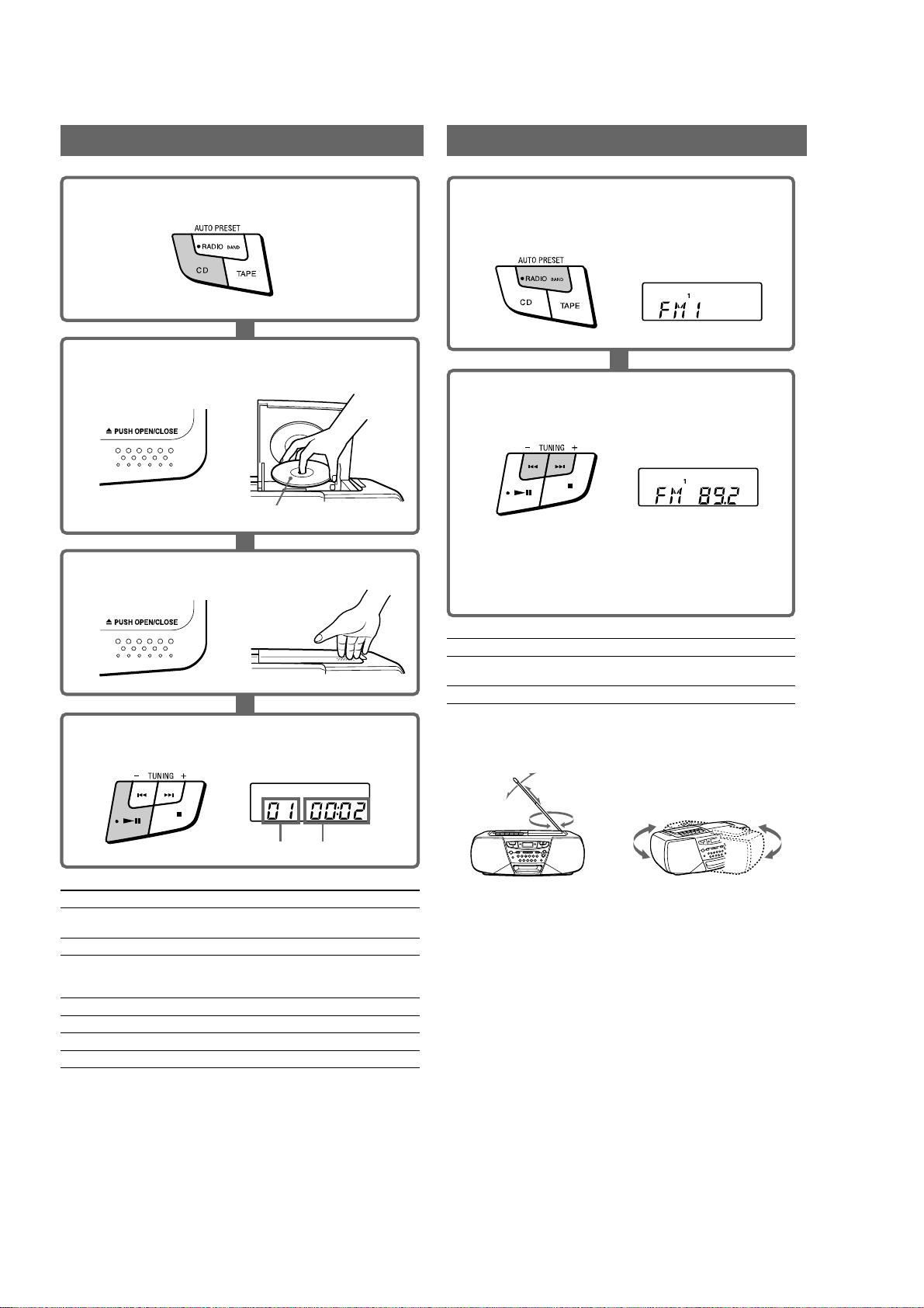
Playing a CD
Listening to the radio
1 Press CD (direct power-on).
2 Press Z PUSH OPEN/CLOSE down to open the CD
compartment and place a CD in the CD compartment.
c
With the labeled side up
3 Close the CD compartment.
c
1 Press RADIO BAND•AUTO PRESET until the band you
want appears in the display (direct power-on).
Each time you press the button, the indication changes as
follows: “FM1” t “FM2” t “AM”.
Display
2 Hold down TUNING + or – (TUNE + or – on the remote,
CFD-S32 only) until the frequency digits begin to change
in the display.
Display
The player automatically scans the radio frequencies and
stops when it finds a clear station.
If you can't tune in a station, press the button repeatedly
to change the frequency step by step.
To
adjust the volume
turn on/off the radio
Press
VOLUME +, – (VOL +, – on the remote,
CFD-S32 only)
POWER
4 Press u (N on the remote, CFD-S32 only).
The player plays all the tracks once.
Display
Track number Playing time
To
adjust the volume
stop playback
pause playback
go to the next track
go back to the previous track
remove the CD
turn on/off the player
Press
VOLUME +, – (VOL +, – on the remote,
CFD-S32 only)
x
u (X on the remote, CFD-S32 only)
Press the button again to resume play after
pause.
>
.
Z PUSH OPEN/CLOSE
POWER
To improve broadcast reception
Reorient the antenna for FM. Reorient the player itself for AM.
FM AM
Tips
• The "FM1" and "FM2" bands have the same functions. You can store
the stations you want separately in "FM1" and "FM2".
• If the FM broadcast is noisy, press PLAY MODE•MONO/ST until
"Mono" appears in the display and the radio will play in monaural.
– 6 –
Use TYPE I (normal) tape only.
Use TYPE I (normal) tape only.
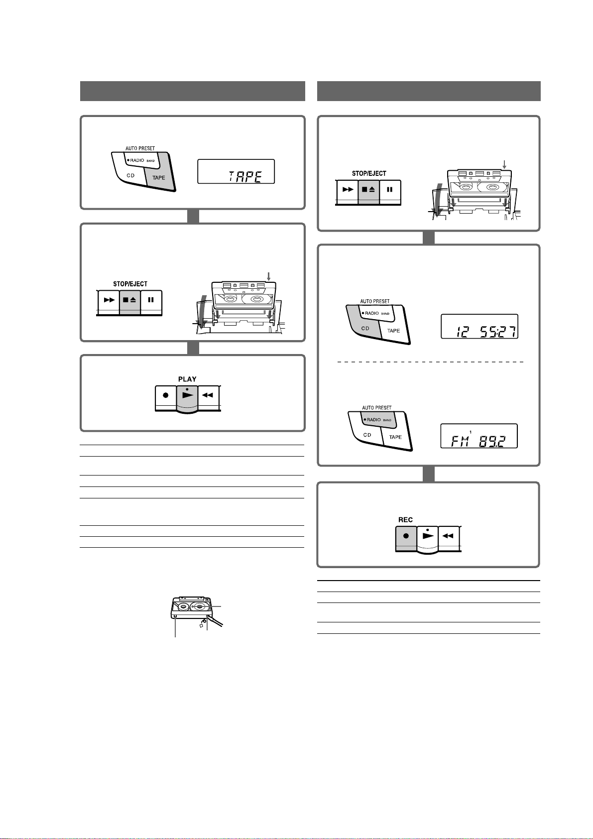
RecordingPlaying a tape
1 Press TAPE (direct power-on).
Display
2 Press xZ to open the tape compartment and insert a
recorded tape. Close the compartment.
With the side you want to
play facing upward
c
3 Press N.
1 Press xZ to open the tape compartment and insert a
blank tape.
With the side you want to
record on facing upward
c
2 Select the program source you want to record.
To record from the CD player
Press CD and insert a CD (See "Playing a CD").
Display
To record from the radio
Press RADIO BAND•AUTO PRESET and tune in the
station you want (See "Listening to the radio").
Display
To
adjust the volume
stop playback
fast-forward or rewind the tape
pause playback
eject the cassette
turn on/off the player
Notes on cassettes
• Break off the cassette tab from side A or B to prevent accidental
recording. If you want to reuse the tape for recording, cover the broken
tab with adhesive tape.
Tab for side B
• The use of a cassette with more than 90 minutes of play time is not
recommended except for long, continuous recording or playback.
Press
VOLUME +, – (VOL +, – on the
remote, CFD-S32 only)
xZ
M or m
X
Press the button again to resume play
after pause.
xZ
POWER
Side A
Tab for side A
3 Press z to start recording.
(N is depressed automatically).
To
stop recording
pause recording
turn on/off the player POWER
Tips
• Adjusting the volume or the audio emphasis will not affect the
recording level.
• For the best results, use the AC power as a power source for recording.
• To erase a recording, proceed as follows:
1 Insert a tape with the recording you want to erase.
2 Press TAPE.
3 Press z.
Press
xZ
X
Press the button again to resume recording.
– 7 –
SECTION 3
DISASSEMBLY
• The equipment can be removed using the following procedure.
Set Cabinet (Front) Sub Assy Wires
Note : Follow the disassembly procedure in the numerical order given.
Cabinet (Upper) Assy
Secondary, Power Board
Tuner Board
VOL SEL Board
Tape Mechanism Block
CD Mechanism Block
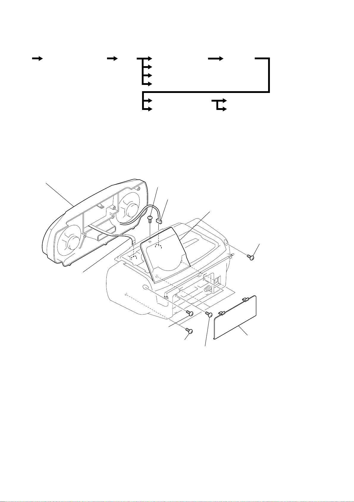
3-1. CABINET (FRONT) SUB ASSY
9 cabinet (front) sub assy
6 BVTP 3x12
7 CNP323
Main Board
Holder Assy, Cassette
PRE Board
lid (CD)
8 CNP501
2 BVTP 3x10
5 BVTP 3x10
1 lid, battery case
4 BVTP 3x12
3 BVTP 3x10
– 8 –
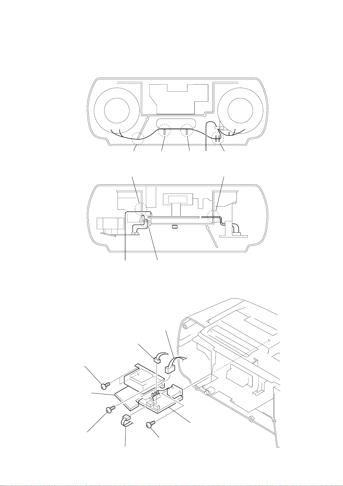
3-2. WIRES
)
Put flat cable and wires between the cabinets and push them in the
grooves located at A to G in the figure to prevent disconnection
before assembling the set.
CABINET (FRONT
AB
E
from SP
3-3. SECONDARY BOARD, POWER BOARD
CD
G
CABINET (REAR)
F
3 BVTP 3x10
SECONDARY board
2 BVTP 3x10
5 CNP901
4 CNP902
6 CN905
1 BVTP 3x10
7 POWER board
– 9 –
3-4. VOL SEL BOARD
(E4 model only)
• Abbreviation
E4 : AC 110-120V/220-240V area in E model
2 cover (VOL SEL)
3 VOL SEL board
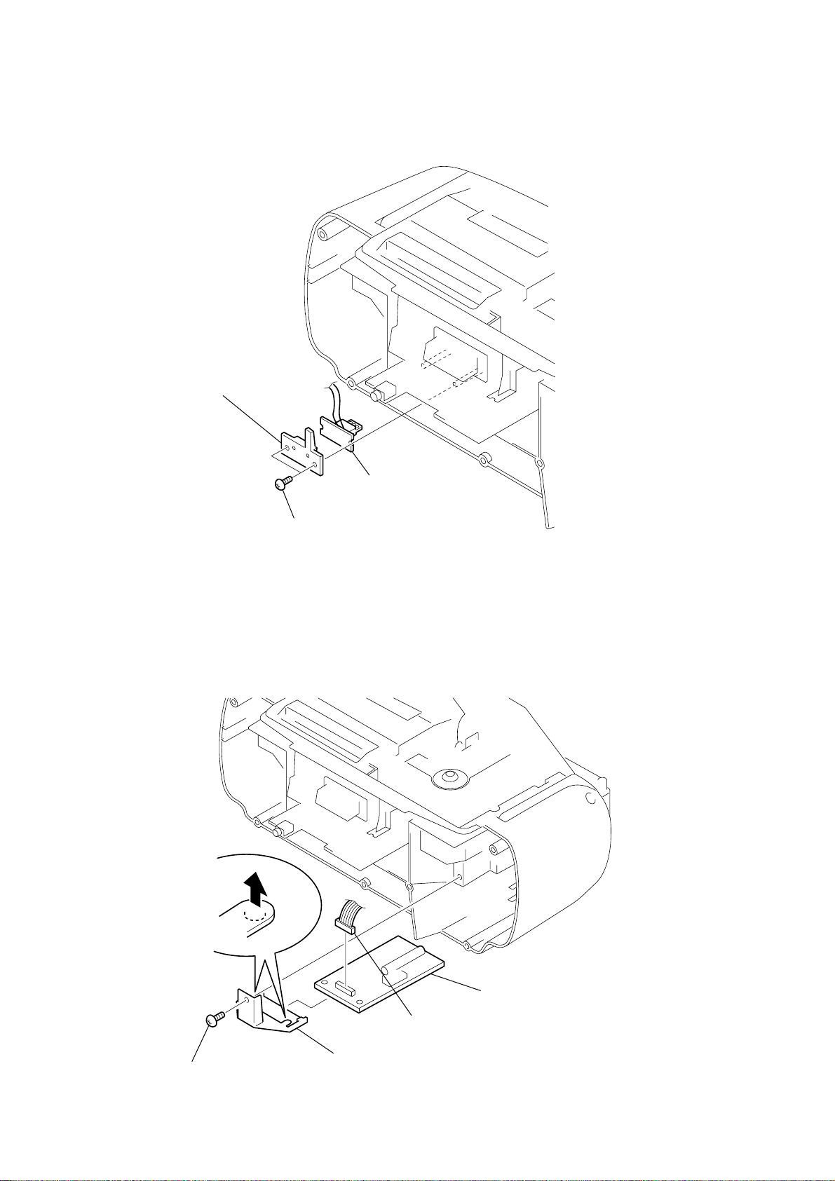
3-5. TUNER BOARD
1 BVTP 3x10
4
2 BVTP 3x10
5 TUNER board
1 CNP1
3 holder (PWB)(TU)
– 10 –
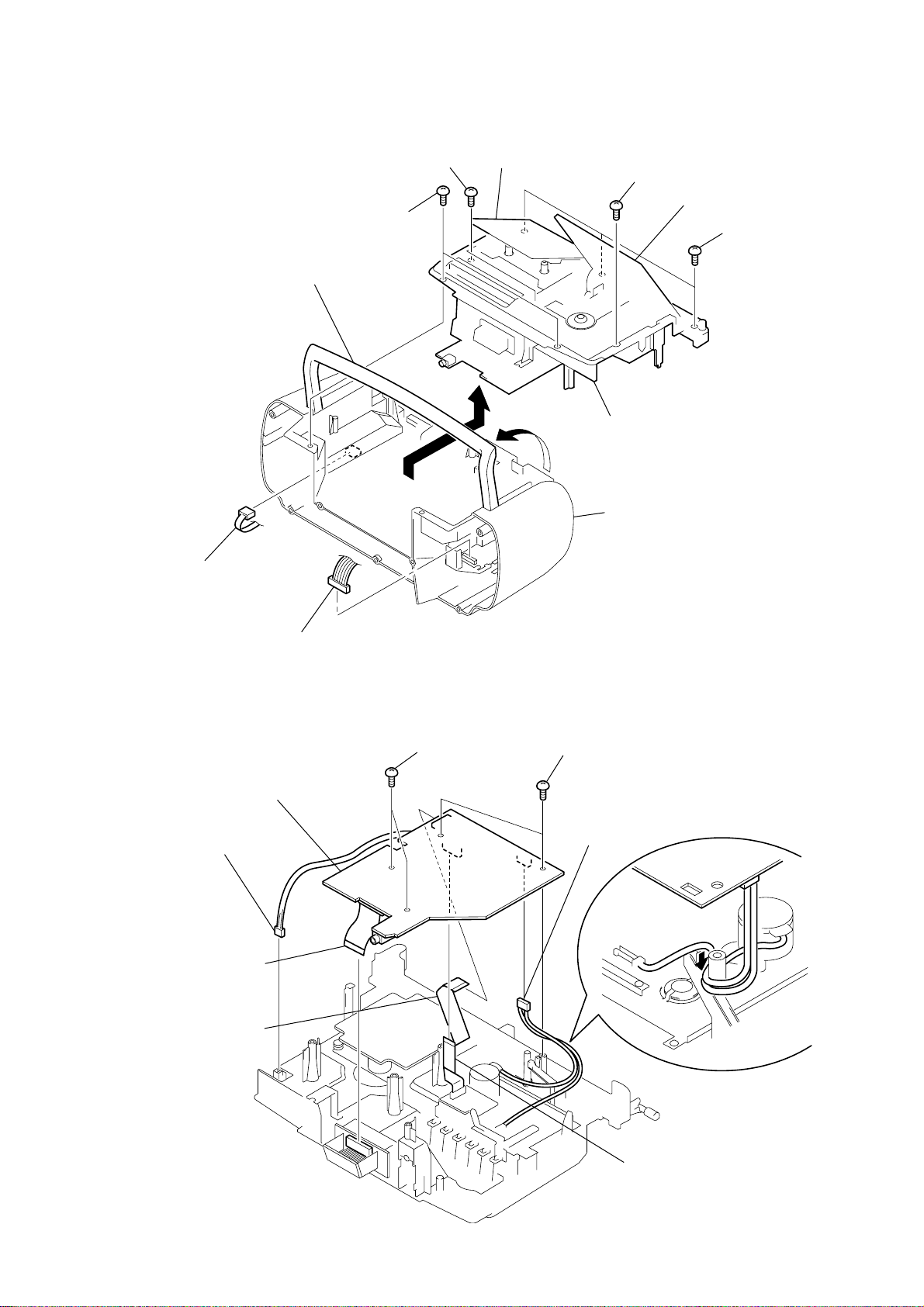
3-6. CABINET (UPPER) ASSY
2 CNP902
5 BVTP 3x10
9 handle
6 BVTP 3x12
3 holder assy, cassette
7 BVTP 3x12
4 lid (CD)
8 BVTP 3x12
0 cabinet (upper) assy
cabinet (rear)
3-7. MAIN BOARD
3 connector
(S501)
4 CNP651
7 CNP502
1 CNP1
8 MAIN board
2 BVTP 3x10
1 BVTP 3x10
5 CNP322
– 11 –
6 CNP505
k
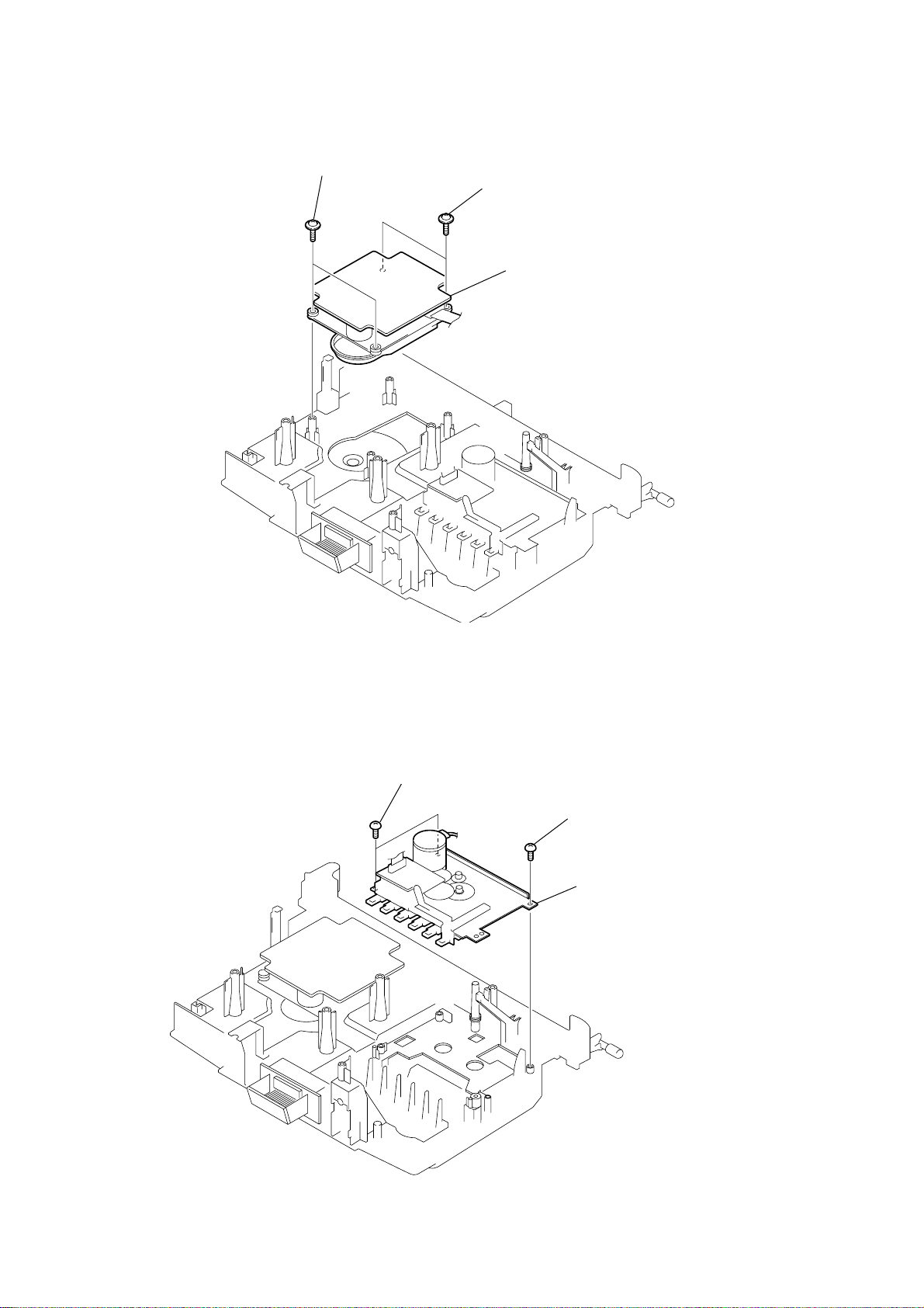
3-8. CD MECHANISM BLOCK
1 PWH 2.6x10
2 PWH 2.6x10
3 CD mechanism block
(KSM-213CDM)
3-9. TAPE MECHANISM BLOCK
1 BVTP 3x10
2 BVTP 3x10
3 tape mechanism bloc
(MF-S22-117)
– 12 –
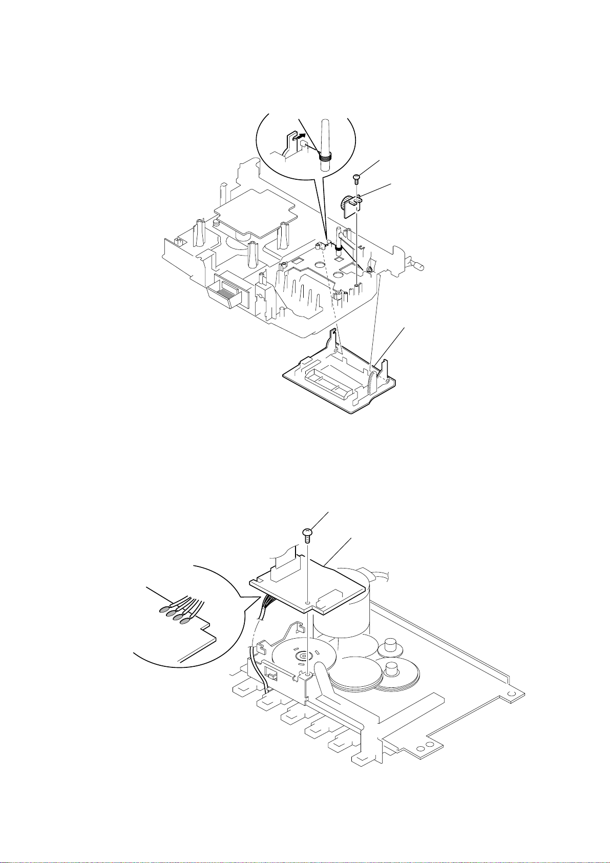
3-10. HOLDER ASSY, CASSETTE
3
1 BVTP 3x10
2 DAMPER
4 holder assy, cassette
3-11. PRE BOARD
3 Removal the solders.
1 BVTP 2x4
2 PRE board
– 13 –
j
)
SECTION 4
MECHANICAL ADJUSTMENTS
SECTION 5
ELECTRICAL ADJUSTMENTS
PRECAUTION
1. Clean the following parts with a denatured-alcohol-moistened
swab :
record/playback head pinch roller
erase head rubber belts
capstan idlers
2. Demagnetize the record/playback head with a head demagnetizer. (Do not bring the head magnetizer close to the erase head.)
3. The adjustments should be performed with the rated power
supply voltage unless otherwise noted.
Torque Measurement
Mode Torque meter Meter reading
FWD CQ-102C
FWD
Back Tension (0.021 – 0.076 oz • inch)
FF CQ-201B
REW CQ-201B
T ape Tension Measurement
Mode Tension meter Meter Reading
FWD CQ-403A
CQ-102C
30 – 70 g • cm
(0.42 – 0.97 oz • inch)
1.5 – 5.5 g • cm
more than 60 g • cm
(more than 0.83 oz • inch)
more than 60 g • cm
(more than 0.83 oz • inch)
more than 100 g
(more than 3.53 oz)
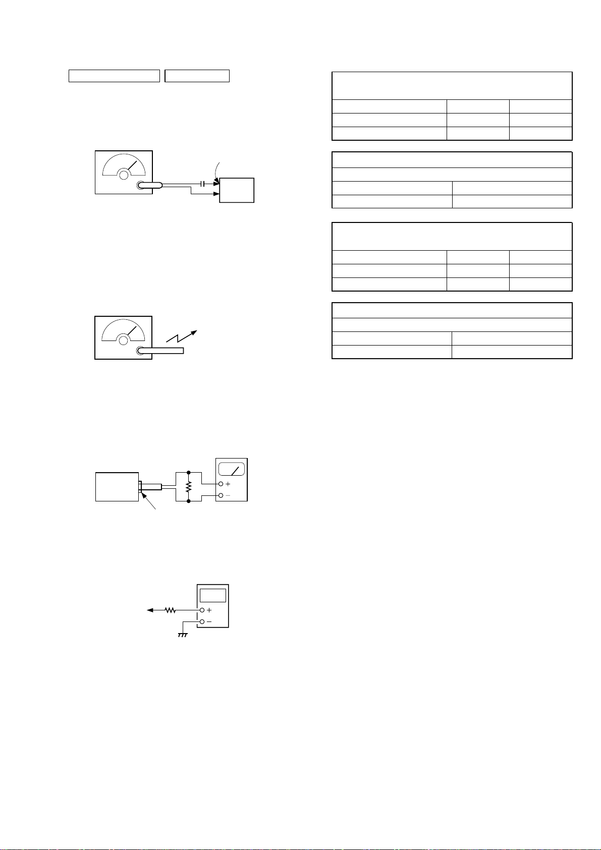
TAPE SECTION 0 dB = 0.775 V
• Standard Output Level
Output terminal HP OUT
load impedance 32 Ω
output signal level 0.25 V (–10 dB)
• Test Tape
Type Signal Used for
WS-48A 3 kHz, 0 dB tape speed adjustment
T ape Speed Adjustment
Procedure:
Mode: playback
test tape
WS-48A
(3 kHz, 0 dB)
set
i
ack (J321
Adjust so that the value on the digital frequency counter is
3,000 Hz.
Specification Value:
Digital frequency counter
2,910 to 3,090 Hz
digital frequency
counter
32 Ω
Adjust so that the frequency at the beginning and that at the end of
tape winding are between 2,955 to 3,045 Hz.
Adjustment Location:
Tape speed adjustment
control inside motor
– 14 –
)
TUNER SECTION 0 dB = 1 µV
• FM Section
Setting:
RADIO (BAND) button: FM
FM RF signal
generator
0.01 µF
75 kHz frequency
deviation by 1 kHz signal
output level : as low as possible
• AM Section
Setting:
RADIO (BAND) button: AM
AM RF signal
generator
Put the lead-wire
antenna close to
the set.
30% amplitude
modulation by
400 Hz signal
TP (JW2)
set
FM FREQUENCY COVERAGE
ADJUSTMENT
Frequency Display 87.5 MHz 108 MHz
Reading on Digital voltmeter 1.6 ± 0.4 V 4.0 ± 0.3V
Adjustment Part <confirmation> L2
FM TRACKING ADJUSTMENT
Adjust for a maximum reading on level meter.
L1 CT1
87.5 MHz 108 MHz
AM FREQUENCY COVERAGE
ADJUSTMENT
Frequency Display 530 kHz 1,710 kHz
Reading on Digital voltmeter 1.1 ± 0.1 V 5.2 ± 0.8V
Adjustment Part L4 <confirmation>
AM TRACKING ADJUSTMENT
Adjust for a maximum reading on level meter.
L3 CT3
620 kHz 1,400 kHz
• For AM adjustment, fix the ferrite-rod antenna (L3) as shown
below and then perform tracking adjustment at L4 and CT3.
Lastly check the voltage.
• Connecting Level Meter (FM and AM)
level meter
(range: 0.5–5 V ac
32 Ω
set
i jack (J321)
• Connecting Digital Voltmeter (FM and AM)
digital
voltmeter
100 kΩ
TP (VT)
• Repeat the procedures in each adjustment several times, and the
frequency coverage and tracking adjustments should be finally
done by the trimmer capacitors.
– 15 –
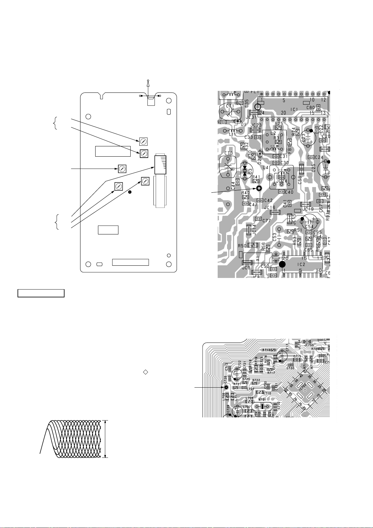
Adjustment Location:
FM
TRACKING
ADJUSTMENT
FREQUENCY
COVERAGE
ADJUSTMENT
L1
CT1
L2
FM
TELESCOPIC
ANTENNA
– tuner board (component side) –
JW2
IC1
TP
(VT)
ANT1
FM
– tuner board (conductor side) –
TP
(VT)
TP(VT)
AM
TRACKING
ADJUSTMENT
L3
L4
CT3
IC2
CNP1
CD SECTION
CD section adjustments are done automatically in this set.
In case of operation check, confirm that focus bias.
FOCUS BIAS CHECK
1. Connect the oscilloscope between IC701 pin qg (or TP (RF))
and GND on CD board.
2. Insert the disc (YEDS-18). (Part No. : 3-702-101-01)
3. Press the CD N X button.
4. Confirm that the oscilloscope waveform is as shown in the
figure below. (eye pattern)
A good eye pattern means that the diamond shape ( ) in the
center of the waveform can be clearly distinguished.
• RF signal reference waveform (eye pattern)
Test Point:
TP
(RF)
– CD board (conductor side) –
TP
(RF)
VOLT/DIV : 50 mV (10 : 1 probe in use)
TIME/DIV : 500 nS
RF level :
1.2 ± 0.3 Vp-p
When observing the eye pattern, set the oscilloscope for AC range
and raise vertical sensitivity.
– 16 –
SECTION 6
DIAGRAMS
6-1. IC PIN DESCRIPTION
• IC501 CXP83620-022Q (SYSTEM CONTROL)
Pin No. Pin Name I/O Pin Description
1 C-SCOR I CD SCOR input
2 RMC I Sircs receiver input
3 MUTE O MUTE output H: Mute
4 ADJ O F TEX frequency division output
5 C-SCLK O CD SENSE read clock output
6 C-SENS I CD SENSE input
7 C-SQCK O CD Sub-Q read clock output
8 C-SQSO I CD Sub-Q data input
9 C-XRST O CD system reset output
10 C-CLOCK O CD system clock output
11 C-LATCH O CD system latch output
12 C-DATA O CD command data output
13 C-AGCCONT O CD AGC control output
14 R-COUNT I Tuner PLL data input
15 R-CLOCK O Tuner PLL clock output
16 R-DATA O Tuner PLL data output
17 R-LATCH O Tuner PLL latch output
18 V-LATCH O Volume latch output Not used. (Open)
19 V-DATA O Volume data output
20 V-CLOCK O Volume clock output
21 P-CON O System power control output H: PCON
22 REG CHK I Regulator check signal input
23 REC I Tape record signal input H: REC
24 SDA I/O EEPROM input/output
25 – 28 KEY-1 – 4 I Key input
29 MODE CHECK I Mode set input
30 RST I System reset input
31 EXTAL I Oscillation input (4.19 MHz)
32 XTAL O Oscillation output (4.19 MHz)
33 VSS — GND
34 VL O LCD drive port ON/OFF output
35 – 37 VLC3 – 1 O LCD drive voltage output
38 – 41 COM0 – 3 O LCD drive common output
42 – 58 SEG0 – 16 O LCD drive segment output
59 SEG17 O LCD drive segment output Not used. (Open)
60, 61 NC — Not used. (Open)
62 INIT O Initial set signal output
63 TONE O TONE control output L: TONE
64 MEGA BASS O MEGA BASS control output H: MEGA BASS
65 BT-CHK I Battery check input H: BT-CHK
66 MT-CONT I MT control input H: MT-CONT
67 ISS1 O ISS1 output H: ISS1 Not used. (Open)
68 ISS2 O ISS2 output H: ISS2 Not used. (Open)
69 TAPE O Tape function output H: Tape
70 RADIO O Tuner function output H: Radio
71 CD O CD function output H: CD
72 VDD — Power supply pin (+3.3 V)
73 TX O Oscillation output (150 kHz)
74 TEX I Oscillation input (150 kHz)
Pin No. Pin Name I/O Pin Description
75 NC — Not used. (Open)
76 A-MUTE O Audio mute output H: Mute
77 SCL O EEPROM clock output
78 EC I Event counter input
79 TC-PLAY I Tape play switch input L: Tape
80 C-DOOR I CD door open/close switch input L: Close
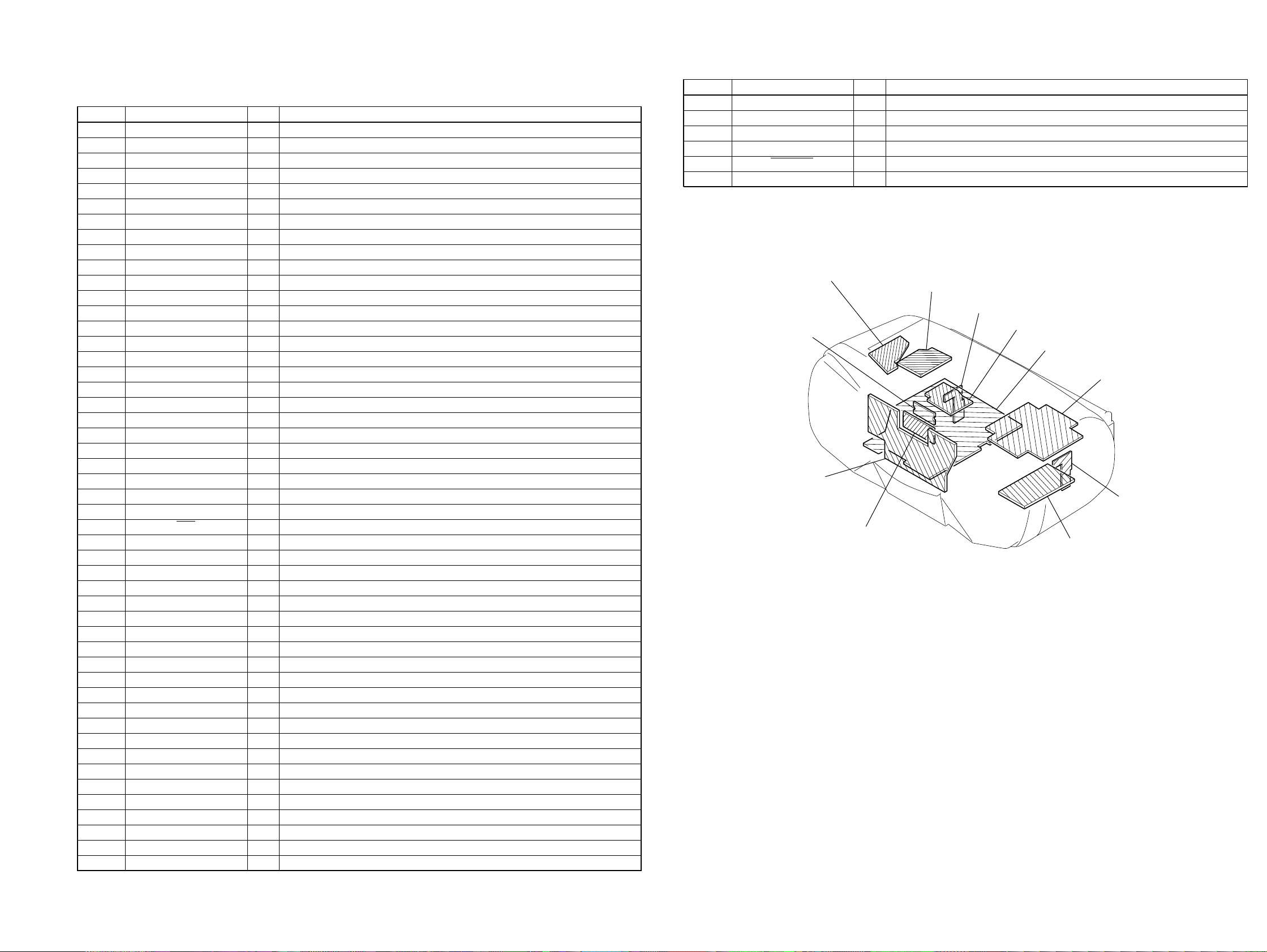
6-2. CIRCUIT BOARDS LOCATION
SECONDARY board
VOL SEL board
(E4 model only)
CONTROL board
LCD board
• Abbreviation
E4 : AC 110-120V/220-240V area in E model
POWER board
BATTERY board
PRE board
MAIN board
TUNER board
CD board
HALF BATTERY board
– 17 – – 18 –
CFD-S22/S32
6-3. BLOCK DIAGRAM — CD SECTION —
A
C
B
D
LD
PD
E
F
VREF
OPTICAL PICK-UP
BLOCK
(KSS-213C)
TRACKING
COIL
FOCUS
COIL
M702
SLED
MOTOR
M701
SPINDLE
MOTOR
(LIMIT)
• Signal path
: CD
R-ch : same as L-ch.
Abbreviation
CND : Canadian model
E4 : AC 110-120V/
220-240V area in E model
E92 : AC 120V area in E model
MX : Mexican model
S702
S501
CD DOOR
OPEN/
CLOSE
CD BOARD
SYSTEM SERVO PROCESSOR,
RF AMP
CNP701
12
10
11
13
LD POWER
7
CONTROL
5
14
9
16
3
2
4
1
M
M
Q701
VREF
LD ON
SWITCH
Q702
VDD(SW)
04
PD1
PD2
5
LD
2
PD
3
E
8
F
7
VC
10
LD ON
19
T+
13
T–
14
F+
17
F–
18
SL+
12
SL–
11
SP+
15
SP–
16
VDD
IC701
TRACKING
COIL
DRIVE
FOCUS
COIL
DRIVE
SLED
MOTOR
DRIVE
SPINDLE
MOTOR
DRIVE
SLED/SPINDLE
MOTOR DRIVE,
TRACKING/FOCUS
COIL DRIVE
IC703
D511
D509
RFO
AGC CONT
TFDR
TRDR
FFDR
FRDR
MUTE
SFDR
SRDR
SPIN
VREF
REG,AC
BATTERY
CHECK
Q501-504
VREF
RFAC
51
RFDC
43
FE
39
SE
40
TE
41
VC
38
CE
42
TFDR
TF
30
TR
TRDR
31
FFDR
FF
32
FRDR
FR
33
SFDR
SF
28
SRDR
SR
29
C-DOOR
80
BT-CHK
65
MT-CONT
66
154
FE
13
TE
11
18
TF
2
TR
3
FF
24
FR
23
20
SF
5
SR
6
25
27
VREF
ASYMMETRY
CORRECTION
&
DIGITAL
PLL
OPERATIONAL
AMPLIFIER
ANALOG SWITCH
&
A/D
CONVERTER
SERVO
DSP
&
PWM
GENERATOR
CNP702(1/2)
3 6 13 12 4 9 8 7 5
15 12 5 6 14 9 10 11 13117
CNP502(1/2)
13
CONT
C-AGC
RADIO
70
RADIO
6V REG
Q513,514
CD
3.3V REG
Q511,512
EFM DEMODULATOR
INTERNAL
DIGITAL
CLV
MDP
26 27 14 8 1 202 5 6 7 66 679 3
CD
SYSTEM CONTROL
IC501 (1/2)
AUDIO 6VRA6V
COM 3.3VCD3.3V
DIGITAL SIGNAL PROCESSOR
BUS
SUB CODE
PROCESSOR
INTERFACE
XLON
SSTP
71
SENS
6 8 7 12 11 10 5 91
CD
3.3V
CPU
SQSO
SQCK
C-SENS
C-SQCK
C-SQSO
3 2
IC702
INTERFACE
SCOR
C-SCOR
3.3V REG
IC502
D/A
DATA
C-DATA
VDD
XLAT
CLK
C-LATCH
3
SCLK
C-SCLK
C-CLOCK
D956
OVER
SAMPLING
DIGITAL
FILTER
&
SERIAL
IN
INTERFACE
XRST
16.9344MHz
C-XRST
KH321
AC-HI
PWM
AMP
PWM
AMP
SERVO
INTERFACE
&
SERVO AUTO
SEQUENCER
TIMING
LOGIC
XTAO
XTAI
X701
SECONDARY BOARD
EXCEPT US,E92,MX MODEL
CNP902
3 3
11
22
AOUT1
LOUT1
AOUT2
LOUT2
US,E92,MX MODEL
POWER
BOARD
CNP702(2/2) CNP502(2/2) CNP505(1/3)
70
72
77
75
CD R
(US MODEL)
VDD
VDD
F902
D901 - 904
15 3 3
P. CONT
POWER
SWITCH
Q951
COM 3.3V
AUDIO 6V
CNP901
2
POWER
SWITCH
Q952,953
VDD(SW)
T901
POWER
TRANSFORMER
1
3
MAIN BOARD (1/2)
D955
COM
3.3V REG
Q957
D951 D952
VOL SEL BOARD
CNP905
EXCEPT E4 MODEL
CNB901(1/2)
1
CNB901(2/2)
3
BATTERY
BOARD
4
EXCEPT US MODEL
AUDIO
6V REG
Q955
F901
E4 MODEL
DRY BATTERY
SIZE " D "
(IEC DESIGNATION R20)
6PCS,9V
CNP904
1
2
HALF
BATTERY
BOARD
CD L
1
E4 MODEL
VOLTAGE SELECTOR
220-240V
110-120V
CNJ901
AC IN
4.5V
4.5V
S901
– 19 – – 20 –
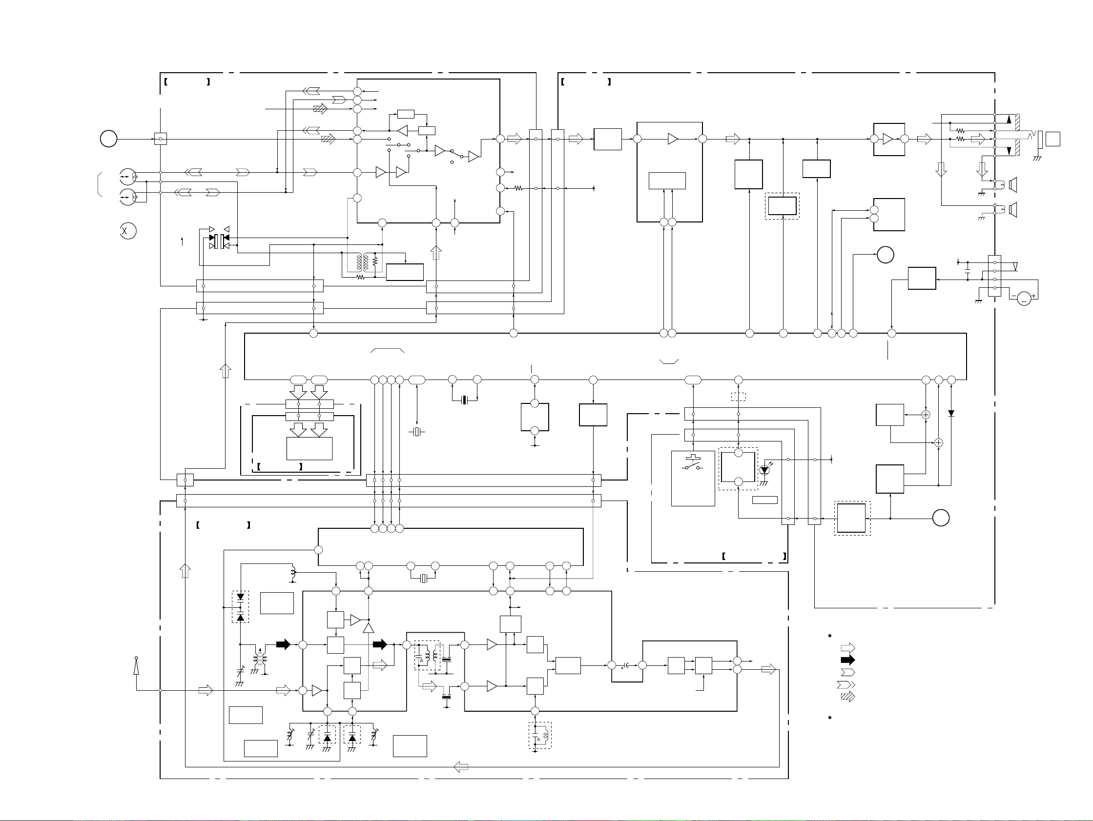
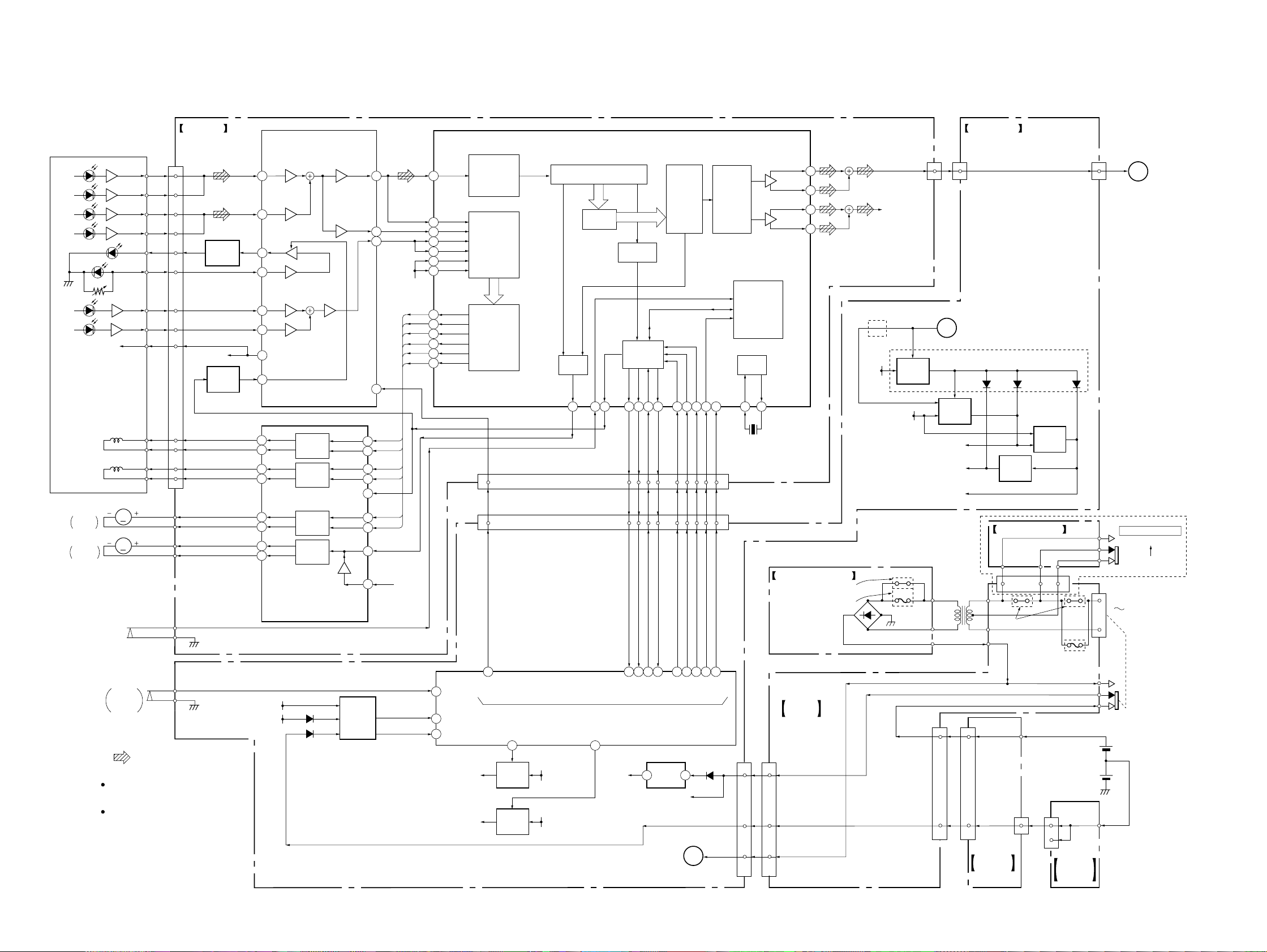
6-4. BLOCK DIAGRAM — MAIN SECTION —
CFD-S22/S32
1
RECORD/PLAYBACK
L-CH
R-CH
CD L
HRP301
HEAD
HE301
ERASE HEAD
ANT1
FM
TELESCOPIC
ANTENNA
3
CNP301(2/3)
CNP505(2/3)
04
PRE BOARD
CNP301(1/3)
S301
(REC/PB)
REC
PB
1
6
CD R
-1 -2
10 5
10 5
AUDIO 6V
CNP551
CNP651
LCD BOARD
KH504
TUNER BOARD
L4
AM
D3
FREQUENCY
COVERAGE
L3
AM
FERRITE-ROD
ANTENNA
CT3
CT3,L3
AM
TRACKING
TRACKING
RA6V
CT1,L1
FM
R.RO
9
R.IN
8
R.LIN
14
L.RO
4
L.LIN
24
L.IN
5
6
REF
T301
23
REC
|
SEG0
COM0|COM3
38–41 42–58 73•74 25–28
1-4
21-18
LIQUID CRYSTAL
DISPLAY PANEL
L4
RA6V
22 4 6
RA6V
LCD501
AM
RF-IN
FM
RF-IN
2
FM
RF-OUT
5-21
17-1
AM OSC
SEG16
LP-OUT
AM
OSC
AM
MIX
D1 D2
FM
MIX
FM
OSC
2124
AM IN
11 12
1920
FM OSC
17 16 15 14
FM IN
RA6V
DET
ALC 2
RADIO L
REC
21 22 16
REC BIAS OSC
Q301
TUNER
R-LATCH
R-CLOCK
R-DATA
R-COUNT
TX
TEX
X502
150kHz
5
10293847
1182 3 4
CEDICL
DO
XOUT
20 19
FM/AM FRONT-END, IF DET,
FM STEREO DEMODULATOR
OSC-OUT
MIX-OUT
L2L1 CT1
L2
FM
FREQUENCY
COVERAGE
T1
REC/PB
PRE AMP
IC301
L.RAD
R.RAD
R-CH
SYSTEM CONTROL
IC501 (2/2)
EXTAL32XTAL
31
X501
4.19MHz
PLL
IC2
XIN
X1
75kHz
IC1
CF4
RA6V
7
CF2
RA6V
CNP301
L.LO
20
R-CH
18
17
15
91
91
69
TAPE
MO/ST10IF IN
13
14 17 13 18
IF-OUT
IF
LPF2/MO-ST
BUFFER
AM
IF-IN
FM
IF-IN
R.LO
LINE
TAPE
(3/3)
RESET
IC503
3.3V
IF CUT
DET
DET
RA6V
30
1
2
AM
FM
10
MAIN BOARD (2/2)
CNP505
(3/3)
6
6
8
8
RST
BAND8ST-IND
7
ST-IND
LPF1/BAND
AF
BUFFER
QUAD
T2
CD3.3V
MUTE
3
IF REQ
Q510
1
11
DET-OUT
LINE
AMP
Q121
KH503
CNP1
16 15
VOLUME/SOUND CONTROL
IC302
VIN2
8
LOGIC
CONTROL
CLOCK4DATA
5
20 19
V-DATA
V-CLOCK
VOL
S601-604
S607-626
S605,627 (S32)
S606 (S22)
MPX-IN
FM
MPX
VOUT2
7
KEY1|KEY4
2-5 7
2-5 7
MUTE
IF CUT
MEGA
BASS
CONTROL
Q122
64
MEGA BASS
RMC
2
(S32)
1
REMOTE
CONTROL
IC601
3
(S32)
CONTROL BOARD
R-OUT
11
L-OUT
12
(S32)
CNP601
D601
OPR/BATT
R-CH
LPF
Q123
63
TONE
CNP501
66
88
MUTE
Q124
P.CONT
24
77
SDA
VDD (SW)
CONTROL
21
SCL
REMOTE
REG
Q509
(S32)
P-CON
76
A-MUTE
Signal path
: FM
: AM
: TAPE PLAY
: TAPE REC
: CD
R-ch : same as L-ch.
POWER AMP
IC304
11
EEPROM
IC504
SDA
5
SCL
6
2
79
MODE
SWITCH
Q507
MODE
SWITCH
CONTROL
Q505,506
5
TC-PLAY
R-CH
TAPE
SWITCH
Q997
62
AC-HI
VDD(SW)
INIT
29
3
REG CHK
MODE CHECK
22
D510
CNP322
1
2
3
4
CAPSTAN/REEL
SP301
SPEAKER
(L-CH)
SP302
SPEAKER
(R-CH)
S304
(TAPE PLAY)
M
M301
MOTOR
J321
i
– 21 – – 22 –
CFD-S22/S32
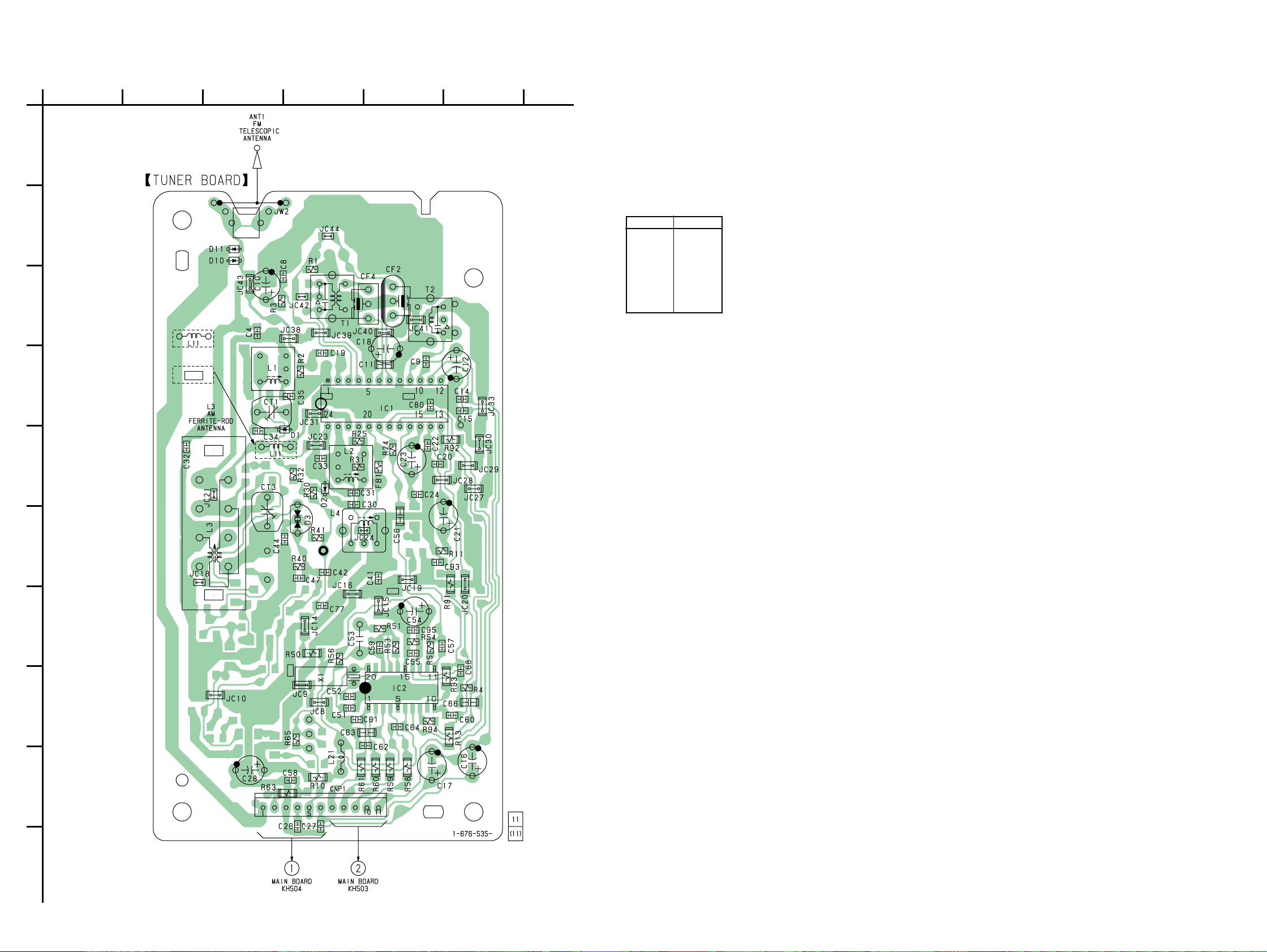
6-5. PRINTED WIRING BOARD — TUNER SECTION — • Refer to page 18 for Circuit Boards Location.
A
B
C
D
1
234567
• Semiconductor
US,CND,E92,
MX MODEL
EA,SP,AR,
AUS MODEL
JC25
Location
Ref. No. Location
D1 E-4
D2 E-4
D3 F-4
D10 B-3
D11 B-3
IC1 D-5
IC2 H-5
E
F
G
H
TP(VT)
Note on Printed Wiring Boards:
• X : parts extracted from the component side.
f
•
• b : Pattern from the side which enables seeing.
• Abbreviation
I
: internal component.
AR : Argentina model
AUS : Australian model
CND : Canadian model
E4 : AC 110-120V/220-240V area in E model
E92 : AC 120V area in E model
MX : Mexican model
SP : Singapore model
J
04
(Page 34) (Page 33)
– 23 – – 24 –
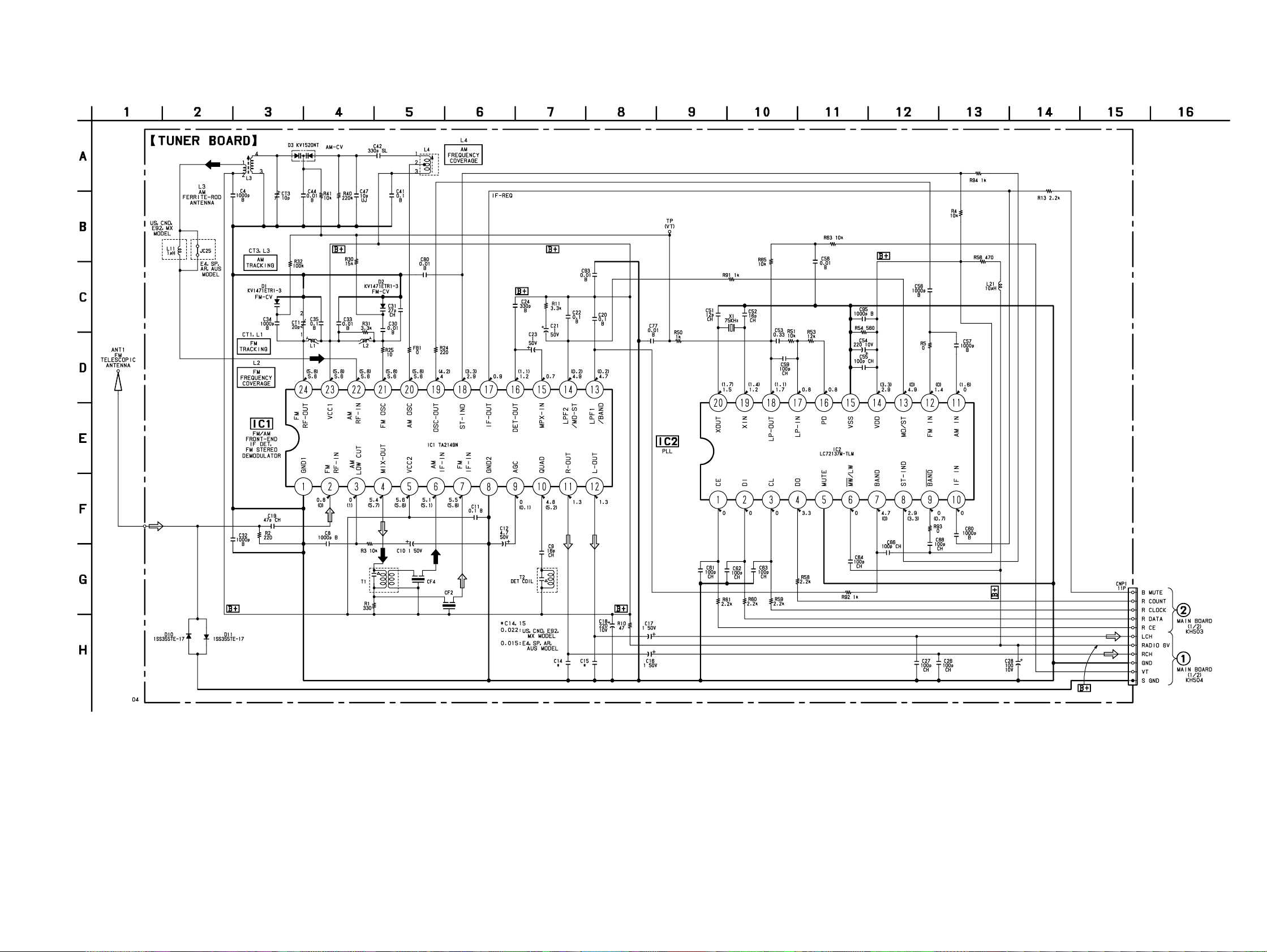
6-6. SCHEMATIC DIAGRAM — TUNER SECTION — • Refer to page 47 for IC Block Diagrams.
CFD-S22/S32
Note on Schematic Diagram:
• All capacitors are in µF unless otherwise noted. pF: µµF
50 WV or less are not indicated except for electrolytics
and tantalums.
• All resistors are in Ω and 1/
specified.
f
•
• U : B+ Line.
• H : adjustment for repair.
• Power voltage is dc 9V and fed with regulated dc power
• Voltage and waveforms are dc with respect to ground
: internal component.
supply from battery terminal.
under no-signal (detuned) conditions.
no mark : FM
( ) : AM
4
W or less unless otherwise
– 25 – – 26 –
(Page 36)
(Page 36)
• Voltages are taken with a V OM (Input impedance 10 MΩ).
Voltage variations may be noted due to normal production tolerances.
• Signal path.
F : FM
f : AM
• Abbreviation
AR : Argentina model
AUS : Australian model
CND : Canadian model
E4 : AC 110-120V/220-240V area in E model
E92 : AC 120V area in E model
MX : Mexican model
SP : Singapore model
 Loading...