

Sony CFD-E55L Service Manual
CFD-E55L
SERVICE MANUAL
Ver 1.0 1999. 11
CD
Section
TAPE
Section
AEP Model
UK Model
Model Name Using Similar Mechanism CFD-Z500
CD Mechanism Type KSM-213CDM
Optical Pick-up Name KSS-213C
Model Name Using Similar Mechanism CFD-Z500
Tape Transport Mechanism Type MF-Z500-117
CD player section
System
Compact disc digital audio system
Laser diode properties
Material: GaAlAs
Wave length: 780 nm
Emission duration: Continuous
Laser output: Less than 44.6 µW
(This output is the value measured at a distance of
about 200 mm from the objective lens surface on
the optical pick-up block with 7 mm aperture.)
Spindle speed
200 r/min (rpm) to 500 r/min (rpm) (CLV)
Number of channels
2
Frequency response
20 - 20,000 Hz +0/–0.5 dB
Wow and flutter
Below measurable limit
Radio section
Frequency range
FM 87.5 - 108 MHz
MW 531 - 1,611 kHz
LW 153 - 279 kHz
SPECIFICATIONS
IF
FM: 10.7 MHz
MW/LW: 450 kHz
Aerials
FM: Telescopic aerial
MW/LW: Built-in ferrite bar aerial
Cassette-corder section
Recording system
4-track 2 channel stereo
Fast winding time
Approx. 120 sec. with Sony cassette C-60
Frequency response
TYPE I (normal): 70 - 13,000 Hz
General
Speaker
Full range: 8 cm (3
3.2 ohms, cone type (2)
Outputs
Headphones jack (stereo minijack)
For 16 - 68 ohms impedance headphones
Maximum power output
2 W + 2 W
Power requirements
For CD radio cassette-corder:
230 V AC, 50 Hz
9 V DC, 6 R20 (size D) batteries
For memory back-up:
4.5 V DC, 3 R6 (size AA) batteries
1
⁄
4
in.) dia.,
Power consumption
AC 17 W
Battery life
For CD radio cassette-corder:
FM recording
Sony manganese SUM-1 (N): approx. 9 h
Sony alkaline AM-1 (N): approx. 19 h
Tape playback
Sony manganese SUM-1 (N): approx. 5 h
Sony alkaline AM-1 (N): approx. 14 h
CD playback
Sony manganese SUM-1 (N): approx. 1.5 h
Sony alkaline AM-1 (N) : approx. 7 h
Dimensions
Approx. 304 × 169 × 262 mm (w/h/d)
3
⁄4 × 10 3⁄
8
(12 × 6
Mass
Approx. 3.6 kg (7 lb. 15 oz) (incl. batteries)
Supplied accessories
AC power cord (1)
Design and specifications are subject to change
without notice.
inches) (incl. projecting parts)
MICROFILM
CD RADIO CASSETTE-CORDER

1. SERVICING NOTES.............................................. 3
2. GENERAL .................................................................. 4
3. DISASSEMBLY ........................................................ 7
CAUTION
Use of controls or adjustments or performance of procedures
other than those specified herein may result in hazardous radiation exposure.
4. MECHANICAL ADJUSTMENTS...................... 12
5. ELECTRICAL ADJUSTMENTS
Tape Deck Section ......................................................... 12
Tuner Section ................................................................. 13
CD Section ..................................................................... 15
6. DIAGRAMS
6-1. Block Diagram – CD Section – .................................... 17
6-2 Block Diagram – TUNER Section – ............................ 19
6-3. Block Diagram – MAIN Section – ............................... 21
6-4. Block Diagram – POWER SUPPLY Section – ............ 23
6-5. Printed Wiring Boards – CD Section – ........................ 27
6-6. Schematic Diagram – CD Section – ............................. 29
6-7. Printed Wiring Boards
– MAIN/POWER SUPPLY Section – ........................... 32
6-8. Schematic Diagram – MAIN (TUNER) Section – ...... 35
6-9. Schematic Diagram
– MAIN (AUDIO)/POWER SUPPLY Section – .......... 40
6-10. IC Pin Function Description .......................................... 43
6-11. Printed Wiring Boards – DISPLAY Section – ............. 45
6-12. Schematic Diagram – DISPLAY Section – .................. 47
7. EXPLODED VIEWS ............................................... 54
8. ELECTRICAL PARTS LIST .............................. 61
This appliance is classified as a CLASS 1 LASER product.
The CLASS 1 LASER PRODUCT MARKING is located on
the rear exterior.
Laser component in this product is capable of emitting radiation
exceeding the limit for Class 1.
– 2 –
SAFETY-RELATED COMPONENT WARNING!!
COMPONENTS IDENTIFIED BY MARK 0 OR DOTTED
LINE WITH MARK 0 ON THE SCHEMATIC DIA GRAMS
AND IN THE PARTS LIST ARE CRITICAL TO SAFE
OPERATION. REPLACE THESE COMPONENTS WITH
SONY PARTS WHOSE PART NUMBERS APPEAR AS
SHOWN IN THIS MANU AL OR IN SUPPLEMENTS PUBLISHED BY SONY.
SECTION 1
SERVICING NOTES
NOTES ON HANDLING THE OPTICAL PICK-UP
BLOCK OR BASE UNIT
The laser diode in the optical pick-up block may suffer electrostatic break-down because of the potential difference generated
by the charged electrostatic load, etc. on clothing and the human
body.
During repair, pay attention to electrostatic break-down and also
use the procedure in the printed matter which is included in the
repair parts.
The flexible board is easily damaged and should be handled with
care.
NOTES ON LASER DIODE EMISSION CHECK
The laser beam on this model is concentrated so as to be focused
on the disc reflective surface by the objective lens in the optical
pick-up block. Therefore, when checking the laser diode emission, observe from more than 30 cm away from the objective lens.
Notes on chip component replacement
• Never reuse a disconnected chip component.
• Notice that the minus side of a tantalum capacitor may be damaged by heat.
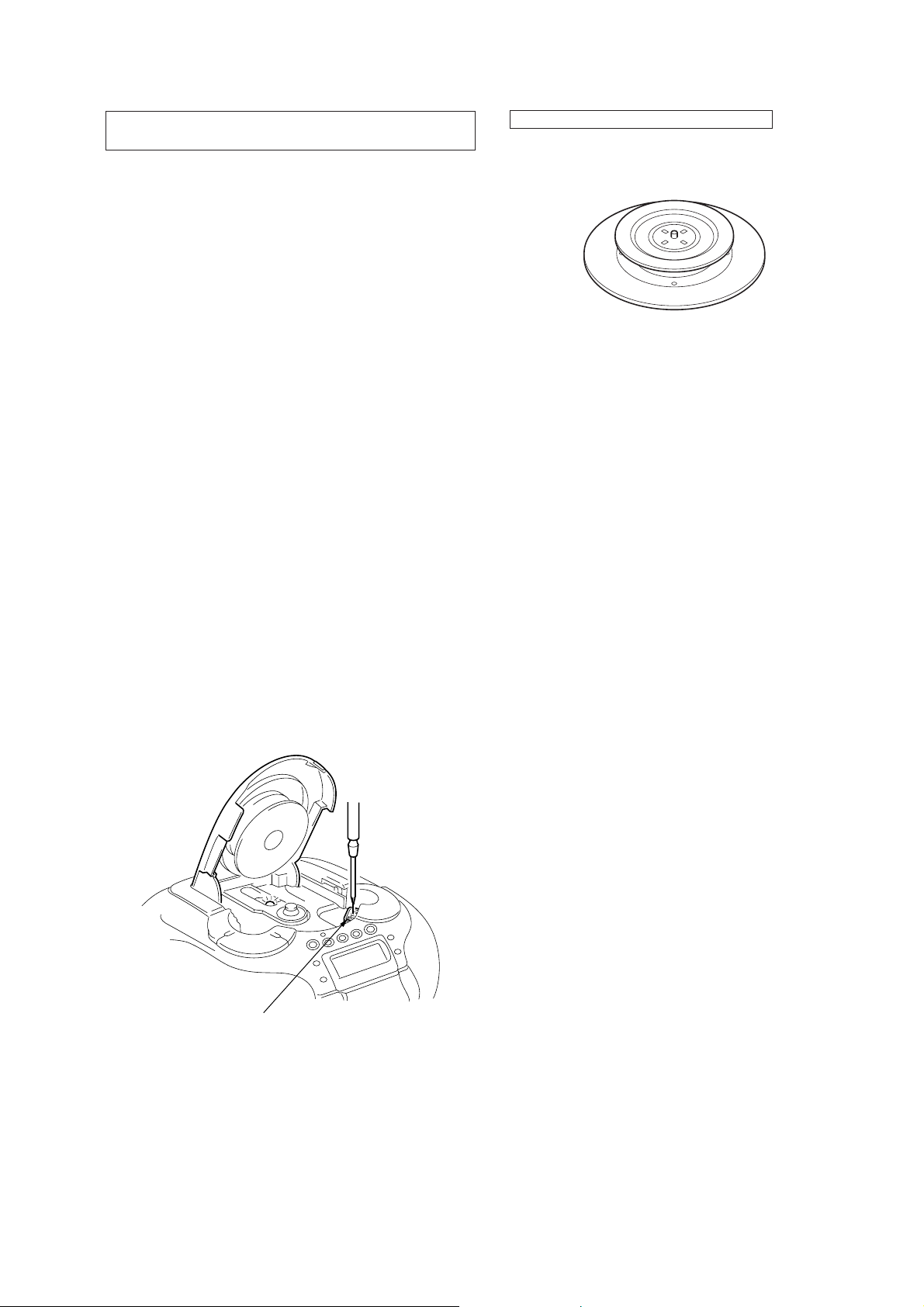
LASER DIODE AND FOCUS SEARCH OPERATION
CHECK
1. T urn PO WER switch on with no disc inserted and make Func-
tion switch to CD position.
2. Open the lid for CD.
3. Turn on S701 as following figure.
4. Press the u button.
5. Confirm the laser diode emission while observing the object-
ing lens. When there is no emission, Auto Power Control circuit or Optical Pick-up is broken.
Objective lens moves up and down three times for the focus
search.
CHUCK PLATE JIG ON REPAIRING
On repairing CD section, playing a disc without the CD lid, use
Chuck Plate Jig.
• Code number of Chuck Plate Jig: X-4918-255-1
S701
– 3 –
Basic Operations
SECTION 2
GENERAL
This section is extracted from
instruction manual.
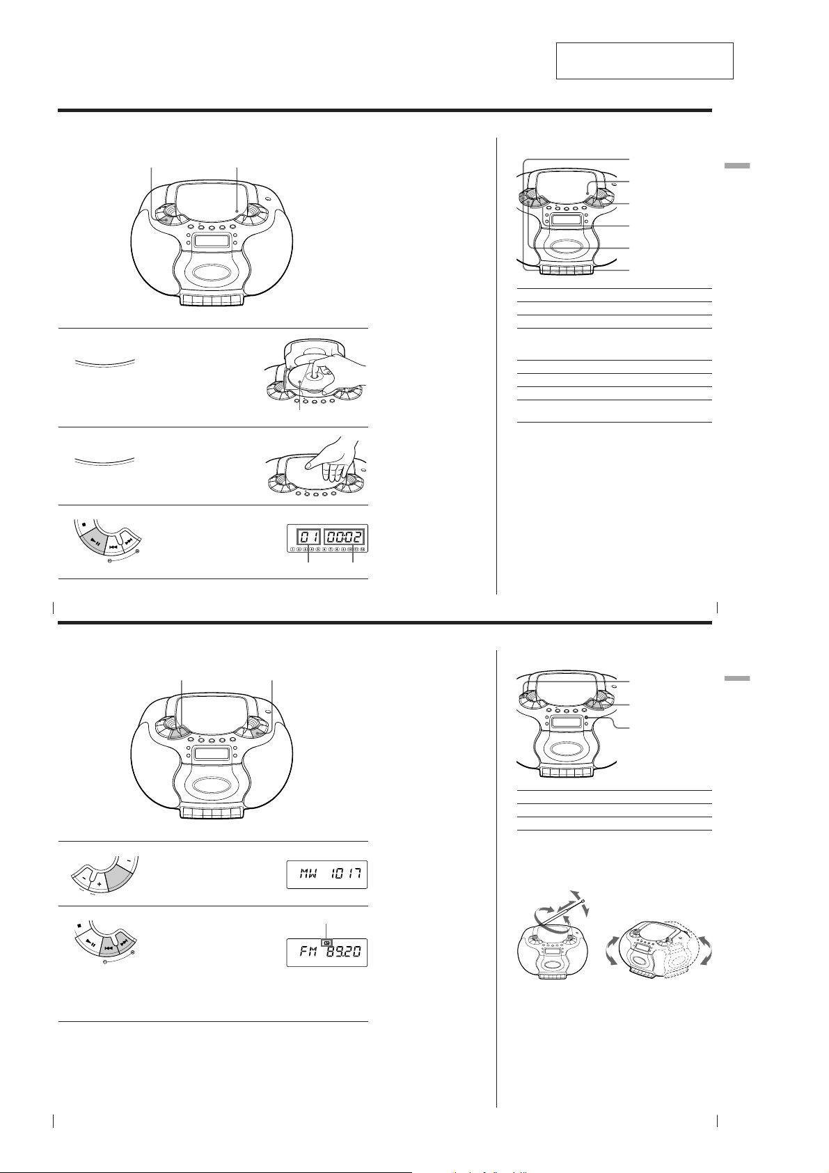
Playing a CD
3
1
Z
H
S
P
U
O
2
O
E
P
S
E
O
N
L
/
C
Z
H
S
P
U
E
P
S
E
O
N
L
/
C
3
T
E
S
E
M
I
T
E
N
U
T
1, 2
Connect the supplied AC power cord (see page 26).
Press ZPUSH OPEN/CLOSE
down to open the CD
compartment and place the CD
on the CD compartment.
With the label side up
Close the lid of the CD
compartment.
Press u.
The player turns on (direct
power-on) and plays all the tracks
once.
Display
Playing timeTrack number
Tip
Next time you want to
listen to a CD, just press
u. The player turns on
automatically and starts
playing the CD.
Use these buttons for additional operations
OPERATE
ZPUSH
OPEN/CLOSE
VOL –, +
., >
u
x
To Press
adjust the volume VOL +, –
stop playback x
pause playback u
go to the next track >
go back to the previous track .
remove the CD ZPUSH OPEN/CLOSE
turn on/off the player OPERATE
Press the button again to
resume play after pause.
(or POWER, see page 2)
Basic Operations
GB
Basic Operations
4
Listening to the radio
Connect the supplied AC power cord (see page 26).
1
VOL
2
T
Press RADIO BAND until the
band you want appears in the
O
display (direct power-on).
I
D
D
A
N
R
A
B
Hold down TUNE TIME SET + or
– until the frequency digits begin
to change in the display.
The player automatically scans
T
E
S
E
M
I
T
E
N
U
the radio frequencies and stops
when it finds a clear station.
If you can't tune in a station,
press the button repeatedly to
change the frequency step by
step.
Basic Operations
GB
5
Use these buttons for additional operations
2
1
Display
Indicates an FM stereo
broadcast
Tips
• If the FM broadcast is
noisy, press PLAY
MODE •MONO/ST ISS
until “Mono” appears in
the display and the
radio will play in
monaural.
• Next time you want to
listen to the radio, just
press RADIO BAND.
The player turns on
automatically and starts
playing the previous
station.
OPERATE
VOL –, +
PLAY MODE
MONO/ST ISS
To Press
adjust the volume VOL +, –
turn on/off the radio OPERATE
To improve broadcast reception
Reorient the antenna for FM. Reorient the player itself
for MW/LW.
for FM
for MW/LW
Basic Operations
GB
6
Basic Operations
– 4 –
Basic Operations
GB
7
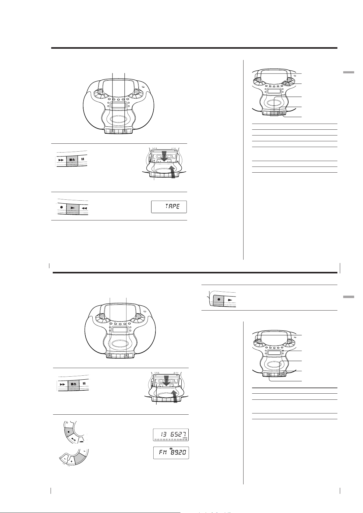
Playing a tape
Connect the supplied AC power cord (see page 26).
1
STOP/EJECT
Press xZ to open the tape
compartment and insert a
recorded tape. Use TYPE I
(normal) tape only. Close the
compartment.
Use these buttons for additional operations
12
With the side you want
to play facing you
Tip
Next time you want to
listen to a tape, just
press N. The player
turns on automatically
and starts playing the
tape.
To Press
adjust the volume VOL +, –
stop playback xZ
fast-forward or rewind the tape M or m
pause playback X
eject the cassette xZ
turn on/off the player OPERATE
OPERATE
VOL –, +
m, M
xZ
X
Press the button again to
resume play after pause.
Basic Operations
GB
8
2
Basic Operations
PLAY
Press N.
The player turns on (direct
power-on) and starts playing.
Recording on a tape
Connect the supplied AC power cord (see page 26).
GB
10
1
STOP/EJECT
2
OPR/BATT
OPERATE
VOL
Basic Operations
Press xZ to open the tape
compartment and insert a blank
tape. Use TYPE I (normal) tape
only.
Select the program source you
want to record.
To record from the CD player,
insert a CD (see page 4) and press
x on the CD section.
To record from the radio, tune in
the station you want (see page 6).
O
I
D
D
A
N
R
A
B
31
Display
With the side you want to
record on facing you
Display
3
REC
Tips
• Adjusting the volume or
the audio emphasis (see
page 28) will not affect
the recording level.
• If the MW/LW program
makes a whistling
sound after you've
pressed z in step 3,
press PLAY MODE•
MONO/ST ISS
(Interference Suppress
switch) repeatedly until
the noise is at a
minimum.
• For the best results, use
the AC power as a
power source.
• To erase a recording,
proceed as follows:
1 Insert the tape whose
recording you want to
erase.
2 Press X.
3 Press N.
4 Press z.
5 Press X.
Press z to start recording
(N is depressed automatically).
Use these buttons for additional operations
To Press
stop recording xZ
pause recording X
turn on/off the player OPERATE
Press the button again to
resume recording.
Basic Operations
OPERATE
PLAY MODE
MONO/ST ISS
xZ
X
N
Basic Operations
GB
9
Basic Operations
GB
11
– 5 –
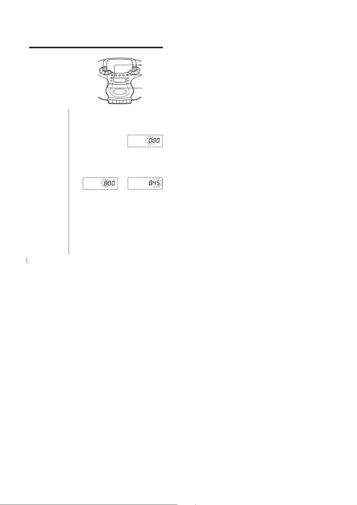
The Timer
Setting the clock
“– –:– –” indication appears in the
display until you set the clock.
Tip
The time display
system:
24-hour system
CLOCK
DSPL
ENT MEM
TUNE
TIME SET –, +
Before you set the clock, connect the power source (see
page 26).
1
Press CLOCK for 2 seconds until the hour digit
flashes.
2
Press TUNE TIME SET + or – until you set the
current hour. Then press DSPL ENT MEM.
The minute digits flash. Set the minutes by
pressing TUNE TIME SET + or – until the correct
minute is displayed.
,
3
Press DSPL ENT MEM.
The clock starts from 00 seconds.
GB
The Timer
20
– 6 –
DISASSEMBLY
d
• This set can be disassembled in the order shown below.
SECTION 3
Set
Lower cabinet
section
Front cabinet
section
Tape mechanism
deck section
Note: Follow the disassembly procedure in the numerical order given.
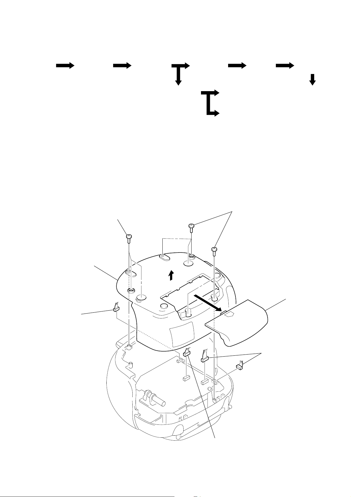
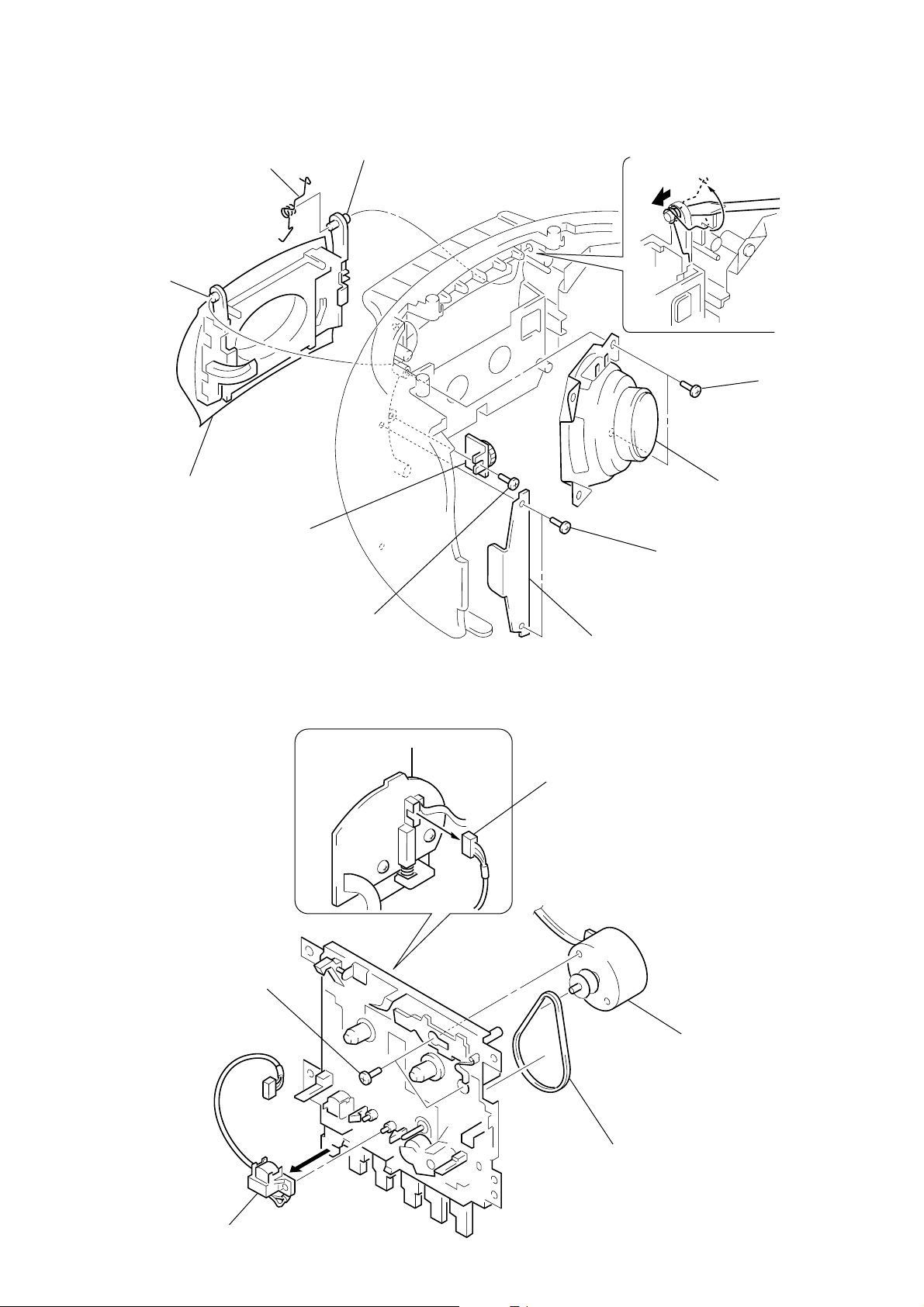
LOWER CABINET SECTION
2
three screws
(BTP3
×
12)
MAIN board
CD board
Cassette lid assy
and cassette holder
Head (HRP301), Motor assy (M301)
and belt
2
five screws
(BTP3
×
12)
Optical pick-up
section
CD lid
section
3
lower cabinet section
4
connector
(CNP310)
1
battery case li
4
two connectors
(CNP704, CNP308)
– 7 –
4
connector
(CNP307)

FRONT CABINET SECTION
2
two screws
(BTP3
×
12)
A
1
three connectors
(CNP302, 303, 309)
2
two screws
(BTP3
×
12)
3
Remove the front
cabinet section in
the arrow
A
direction.
MAIN BOARD
2
1
two connectors
(CNP304, 305)
two screws
(BVTP3
×
10)
1
three connectors
(CNP306, 311, 312)
rear cabinet
section
2
two screws
(BVTP3
×
10)
3
MAIN board
1
connector
(CNP1)
– 8 –
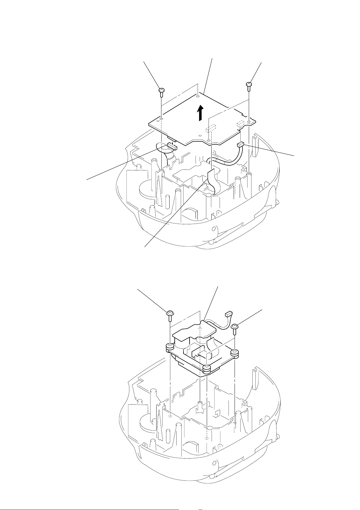
CD BOARD
3
connector
(CNP703)
1
two screws
(BVTP3
×
10)
2
CD board
1
two screws
(BVTP3
×
10)
3
connector
(CNP702)
OPTICAL PICK-UP SECTION
1
two screws
(PWH2.6
4
flat wire (16 core)
(CNP701)
×
10)
2
optical pick-up
section
1
two screws
(PWH2.6
×
10)
– 9 –
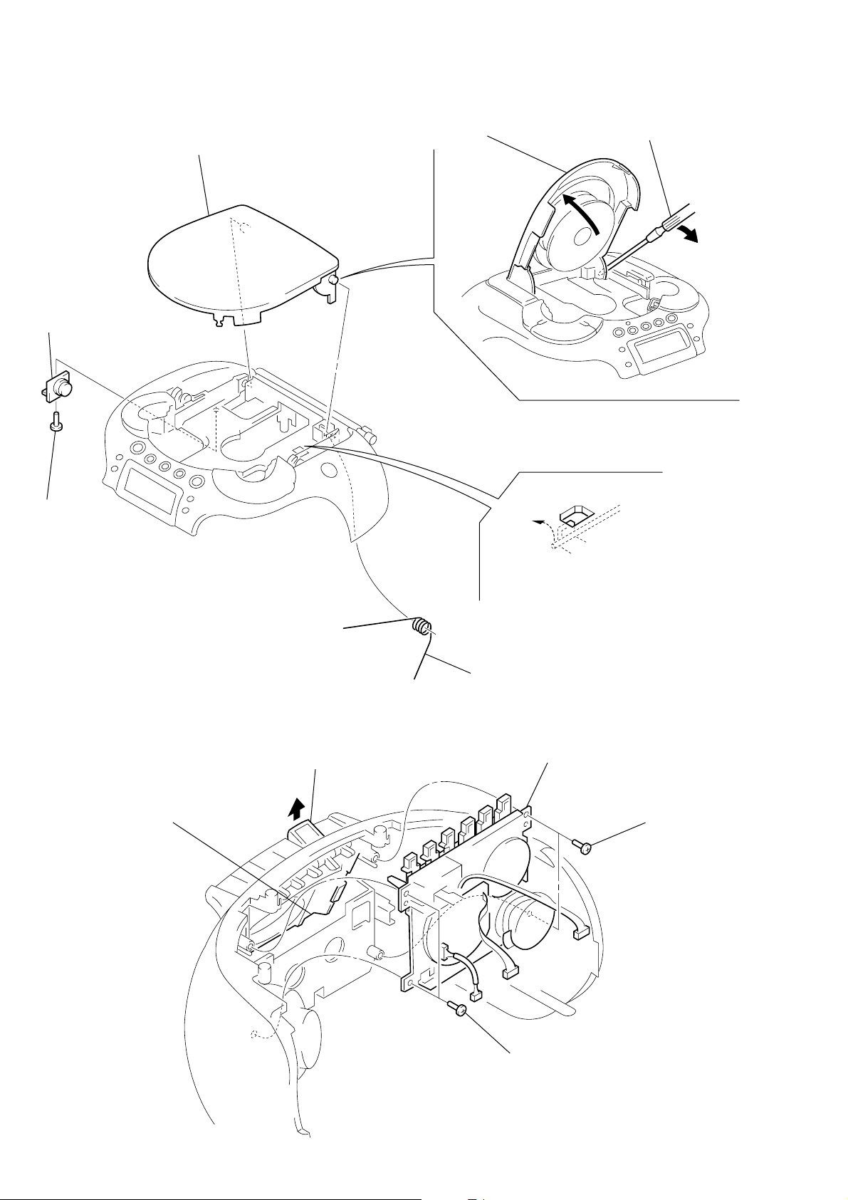
CD LID SECTION
)
2
damper
1
screws
(BVTP3
×
10)
6
CD lid section
4
Open the CD lid section
5
Remove the boss.
TAPE MECHANISM DECK SECTION
1
2
Open the cassette lid assy.
Push the button (ST/EJ).
3
spring (CD)
3
two screws
(BVTP3
4
tape mechanism deck section
3
two screws
(BVTP3
×
10)
×
10
– 10 –
CASSETTE LID ASSY AND CASSETTE HOLDER
)
)
7
8
boss
9
cassette lid assy and
cassette holder
spring
(cassette)
6
damper
8
boss
1
two screws
(BVTP3
3
4
speaker (R ch)
×
10)
two screws
(BVTP3
×
10
5
screw
(BVTP3
×
10)
HEAD (HRP301), MO TOR ASSY (M301) AND BELT
3
two screws
×
5)
(B2.6
1
connector
(CNP301)
2
bracket (SP)
4
motor assy (M301
2
head (HRP301)
– 11 –
5
belt
SECTION 4
r
MECHANICAL ADJUSTMENTS
SECTION 5
ELECTRICAL ADJUSTMENTS
PRECAUTION
1. Clean the following parts with a denatured-alcohol-moistened
swab :
record/playback head pinch roller
erase head rubber belts
capstan idlers
2. Demagnetize the record/playback head with a head demagnetizer. (Do not bring the head magnetizer close to the erase head)
3. Do not use a magnetized screwdriver for the adjustments.
4. After the adjustments, apply suitable locking compound to the
parts adjusted.
5. The adjustments should be performed with the rated power
supply voltage unless otherwise noted.
• Torque Measurement
Mode Torque Meter Meter Reading
FWD CQ-102C
FWD
Back Tension (0.021 – 0.076 oz•inch)
FF CQ-201B
REW CQ-201B
CQ-102C
• T ape Tension Measurement
Mode Tension Meter Meter Reading
FWD CQ-403A
30 – 70 g•cm
(0.42 – 0.97 oz•inch)
1.5 – 5.5 g•cm
more than 60 g•cm
(more than 0.83 oz•inch)
more than 60 g•cm
(more than 0.83 oz•inch)
more than 100 g
(more than 3.53 oz)
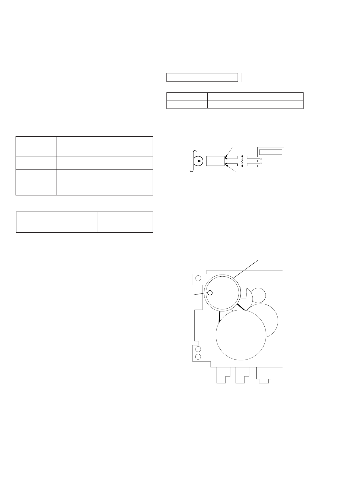
PRECAUTION
Setting:
SOUND control : OFF
MEGA BASS control: OFF
TAPE DECK SECTION 0 dB=0.775 V
Test tape
Type Signal Used for
WS-48A 3 kHz, 0 dB Tape Speed Adjustment
Tape Speed Adjustment
Setting:
Function: TAPE
Test tape
WS-48A
(3 kHz, 0 dB)
Procedure:
1. Playback WS-48A (tape center) in the FWD state.
2. Adjust the volume in CAPSTAN/REEL motor (M301) so that
the frequency counter reading becomes 3,000 Hz.
Specified V alue: 2,985 to 3,015 Hz
3. Confirm that the frequency at the beginning and that at the
end of tape winding are between 2,955 to 3,045 Hz.
MAIN board
CNP311 pin
set
frequency counte
4
3.2
Ω
MAIN board
CNP311 pin
+
–
3
Adjustment Location:
– TAPE deck block –
Tape speed
Adjustment
CAPSTAN/REEL motor
(M301)
– 12 –
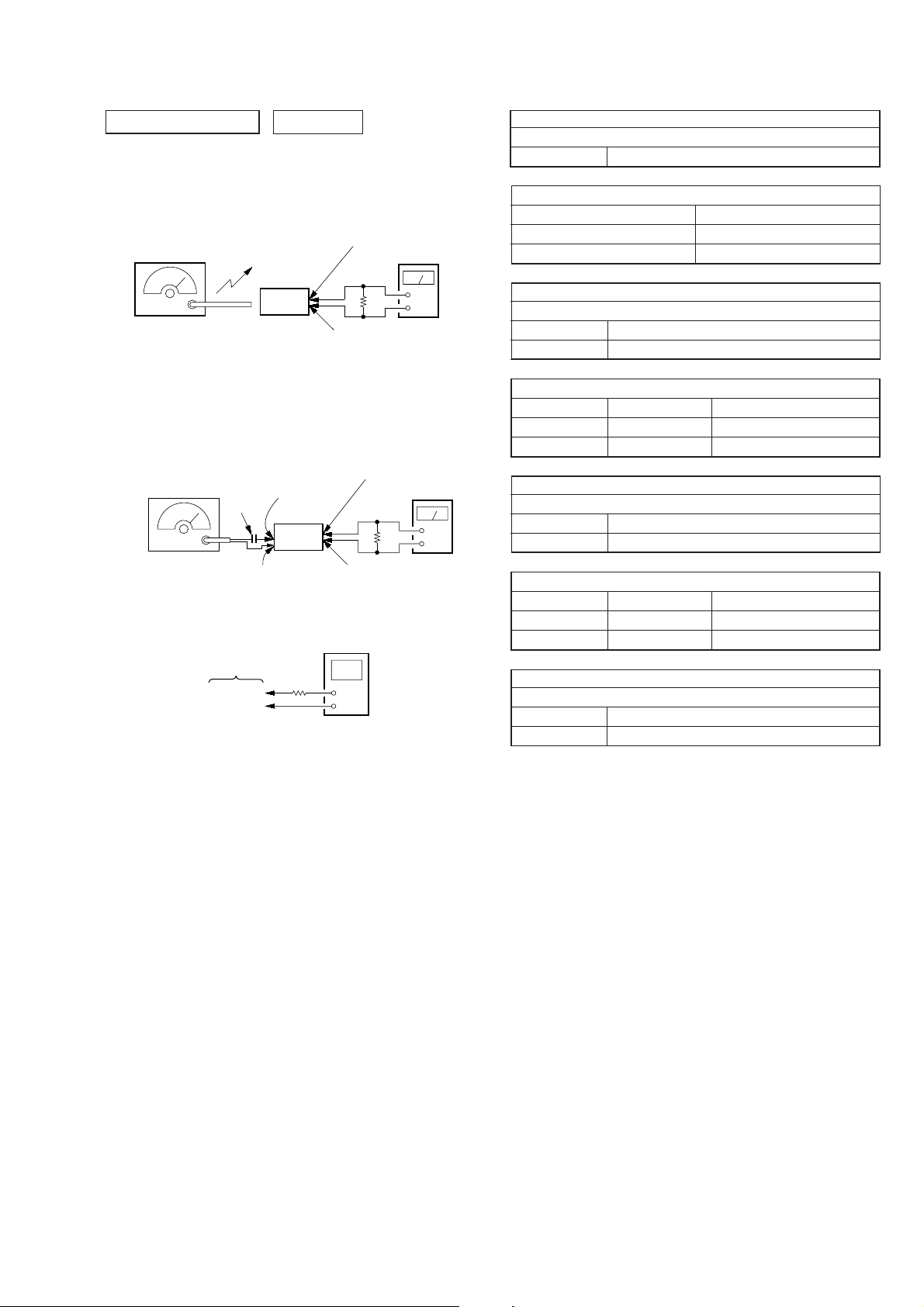
TUNER SECTION 0 dB=1 µV
r
r
[MW/LW]
Setting:
Function : RADIO
BAND button : MW or LW
AM RF signal
generator
30% amplitude
modulation by
400 Hz signal
Output level: as low as possible
Put the lead-wire
antenna close to
the set.
set
MAIN board
CNP311 pin
3.2
Ω
MAIN board
CNP311 pin
4
level mete
+
–
3
AM IF ADJUSTMENT
Adjust for a maximum reading on level meter
T1 450 kHz
MW VCO VOLTAGE CONFIRMATION
Frequency Display Reading on Digital Voltmeter
531 kHz 1.0 ± 0.3 V
1,611 kHz 5.0 ± 0.4 V
MW TRACKING ADJUSTMENT
Adjust for a maximum reading on level meter
L3-1 621 kHz
CT2 1,404 kHz
[FM]
Setting:
Function : RADIO
BAND button: FM
FM RF signal
generator
0.01 µF
22.5 kHz frequency
deviation by 400 Hz
signal
Output level: as low as possible
MAIN board
TP (VT)
TP (GND)
MAIN board
TP (ANT)
set
MAIN board
TP (GND)
100 k
CNP311 pin
3.2
MAIN board
CNP311 pin
digital voltmete
Ω
4
level meter
Ω
+
–
3
MAIN board
• Repeat the procedures in each adjustment several times, and the
tracking adjustments should be finally done by the trimmer capacitors.
• Remove FM antenna in FM adjustment.
LW VCO VOLTAGE ADJUSTMENT
Adjustment Part Frequency Display Reading on Digital Voltmeter
L4 153 kHz 0.6
Confirmation 279 kHz 4.7 ± 0.5 V
LW TRA CKING ADJUSTMENT
Adjust for a maximum reading on level meter
L3-2 162 kHz
CT3 261 kHz
FM VCO VOLTAGE ADJUSTMENT
Adjustment Part Frequency Display Reading on Digital Voltmeter
L2 108 MHz 4.0 ± 0.1 V
Confirmation 87.5 MHz 1.6 ± 0.2 V
FM TRACKING ADJUSTMENT
Adjust for a maximum reading on level meter
L1 87.5 MHz
CT1 108 MHz
+ 0.1 V
– 0.05 V
Adjustment Location: MAIN board (See page 14)
– 13 –
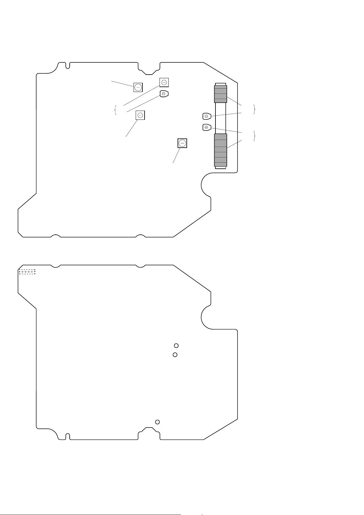
Adjustment Location:
– MAIN BOARD (Component Side) –
T1
AM IF Adjustment
FM T rac king
Adjustment
L1
CT1
L2
FM VCO Voltage
Adjustment
L4
LW VCO Voltage
Adjustment
L3-2
CT3
CT2
L3-1
LW Tracking
Adjustment
MW T rac king
Adjustment
– MAIN BOARD (Conductor Side) –
CNP311
14
TP (GND)
TP (VT)
TP (ANT)
– 14 –
 Loading...