

Page 1
CDX-T69/T69X
SERVICE MANUAL
Ver 1.0 2001.12
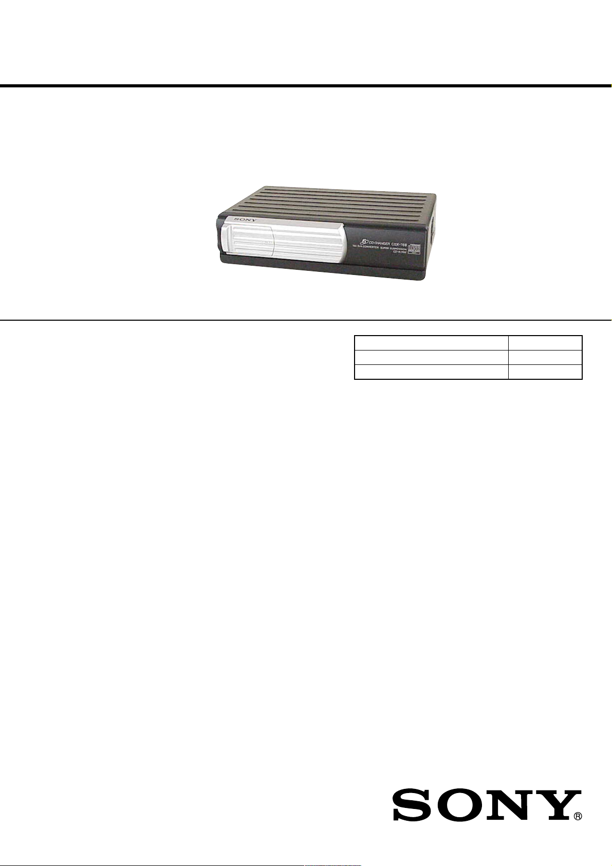
Photo: CDX-T69
SPECIFICATIONS
US Model
Canadian Model
AEP Model
UK Model
CDX-T69
E Model
CDX-T69X
Model Name Using Similar Mechanism CDX-T67
CD Drive Mechanism Type MG-276A-159
Optical Pick-up Name KSS-720A
System Compact disc digital audio system
Laser diode properties Material: GaAlAs
*
This output is the value measured at a distance of 200 mm
from the objective lens surface on the Optical Pick-up Block.
Frequency response 10 – 20,000 Hz
Wow and flutter Below the measurable limit
Signal-to-noise ratio 93 dB
Outputs BUS control output (8 pins)
Current drain 800 mA (during CD playback)
Operating temperature –10°C to +55°C (14°F to 131°F)
Dimensions Approx. 234.4 × 60 × 159.5 mm
Mass Approx. 1.5 kg (3 lb. 5 oz.)
Power requirement 12 V DC car battery
Supplied accessories Disc magazine (1)
Design and specifications are subject to change without
notice.
Wavelength: 780 nm
Emission Duration: Continuous
Laser out-put Power: Less than
44.6 µW*
Analog audio output (RCA pin)
800 mA (during loading or ejecting
a disc)
1
/4 × 2 3/8 × 6 3/8 in.)
(9
(w/h/d) not incl. projecting parts
and controls
(negative ground)
Parts for installation and
connections (1 set)
9-873-430-01 Sony Corporation
2001L0500-1 e Vehicle Company
C 2001.12 Published by Sony Engineering Corporation
COMPACT DISC CHANGER
Page 2
CDX-T69/T69X
L
SERVICING NOTES
NOTES ON HANDLING THE OPTICAL PICKUP BLOCK OR BASE UNIT
The laser diode in the optical pick-up block may suffer electrostatic breakdown because of the potential difference generated by
the charged electrostatic load, etc. on clothing and the human body .
During repair, pay attention to electrostatic breakdown and also
use the procedure in the printed matter which is included in the
repair parts.
The flexible board is easily damaged and should be handled with
care.
NOTES ON LASER DIODE EMISSION CHECK
The laser beam on this model is concentrated so as to be focused
on the disc reflective surface by the objective lens in the optical
pick-up block. Therefore, when checking the laser diode emission, observe from more than 30 cm away from the objectiv e lens.
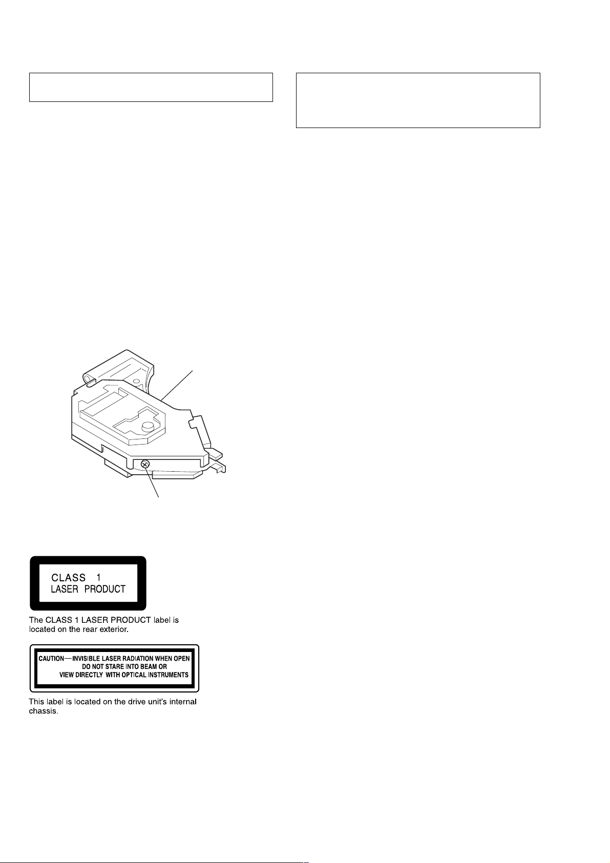
US/Canadian model:
If the optical pick-up block is defective, please replace the whole
optical pick-up block.
Never turn the semi-fixed resistor located at the side of optical
pick-up block.
OPTICA
PICK-UP
BLOCK
CAUTION
Use of controls or adjustments or performance of procedures
other than those specified herein may result in hazardous radiation exposure.
Notes on chip component replacement
• Never reuse a disconnected chip component.
• Notice that the minus side of a tantalum capacitor may be damaged by heat.
Flexible Circuit Board Repairing
• Keep the temperature of the soldering iron around 270 ˚C during repairing.
• Do not touch the soldering iron on the same conductor of the
circuit board (within 3 times).
• Be careful not to apply force on the conductor when soldering
or unsoldering.
SEMI-FIXED
RESISTOR
AEP/UK model:
When replacing the main chassis assy of mechanism deck which
have the “CAUTION LABEL” attached, please be sure to put a
new CA UTION LABEL (3-223-913-11) to the main chassis assy.
SAFETY-RELATED COMPONENT WARNING!!
COMPONENTS IDENTIFIED BY MARK 0 OR DOTTED
LINE WITH MARK 0 ON THE SCHEMATIC DIAGRAMS
AND IN THE PARTS LIST ARE CRITICAL TO SAFE
OPERATION. REPLACE THESE COMPONENTS WITH
SONY PARTS WHOSE PART NUMBERS APPEAR AS
SHOWN IN THIS MANUAL OR IN SUPPLEMENTS PUBLISHED BY SONY.
ATTENTION AU COMPOSANT AYANT RAPPORT
À LA SÉCURITÉ!
LES COMPOSANTS IDENTIFIÉS P AR UNE MARQUE 0
SUR LES DIAGRAMMES SCHÉMATIQUES ET LA LISTE
DES PIÈCES SONT CRITIQUES POUR LA SÉCURITÉ
DE FONCTIONNEMENT. NE REMPLACER CES COMPOSANTS QUE PAR DES PIÈCES SONY DONT LES
NUMÉROS SONT DONNÉS DANS CE MANUEL OU
DANS LES SUPPLÉMENTS PUBLIÉS PAR SONY.
2
Page 3
CDX-T69/T69X
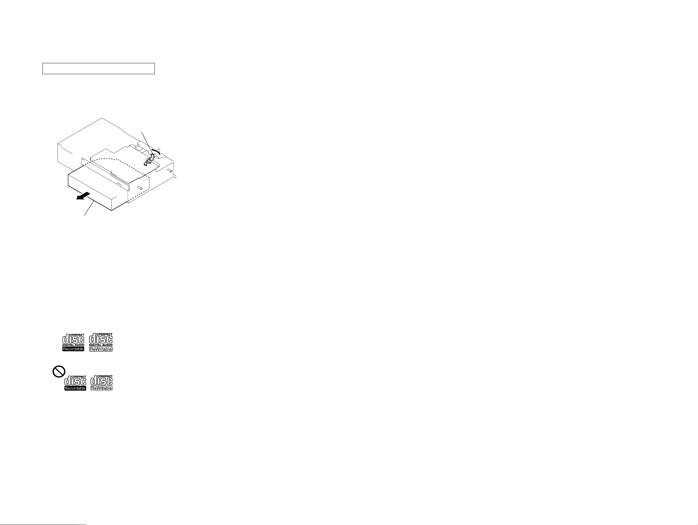
DISC MAGAZINE GETTING OUT PROCEDURE
ON THE POWER SUPPLY IS OFF
Remove the CASE (LOWER. S) beforehand
1) Press the lever (MZ LOCK) in the direction of arrow A.
2) Removal the magazine assy.
Note: Take out the magazine only when the tray is completely within the
magazine. If the disk or tray is sticking out, turn on the power and
eject the magazine.
Lever (MZ LOCK)
A
Magazine assy
TEST DISC
This set can playback a CD-R, CD-RW for audio use. When test
this set, use the following test disc.
Test disc for CD-R: TCD-R082LMT (Part No.: J-2501-063-1)
Test disc for CD-RW: TCD-W082L (Part No.: J-2501-063-2)
Notes on CD-R/CD-RW discs
• You can play CD-Rs/CD-RWs (recordable CDs/
rewritable CDs) designed for audio use on this unit
H).
(fig.
• Some CD-Rs/CD-RWs (depending on the equipment
used for its recording or the condition of the disc) may
not play on this unit.
• You cannot play a CD-R/CD-RW that is not finalized*.
* A process necessary for a recorded CD-R/CD-RW disc to be
played on the audio CD player.
Look for this mark to distinguish CD-Rs/CD-RWs for audio use.
H
This mark denotes that a disc is not for audio use.
TABLE OF CONTENTS
SERVICING NOTES .......................................................... 2
1. GENERAL ................................................................... 4
Installation....................................................................... 5
Connections ..................................................................... 5
2. DISASSEMBLY
2-1. Disassembly Flow ........................................................... 6
2-2. Front Panel (S) Assy, Case (Upper S) ............................ 6
2-3. Mechanism Deck (MG-276A-159) ................................ 6
2-4. JACK Board .................................................................... 7
2-5. Belt (TS) .......................................................................... 7
2-6. MAIN Board ................................................................... 8
2-7. Escutcheon (S), Slide Variable Resistor
(Elevator Height Sensor) (RV301) ................................. 8
2-8. MD Motor Assy (Elevator) (M104)................................ 9
2-9. LE Motor Assy (Chucking) (M103)............................... 9
2-10. RF Board ......................................................................... 10
2-11. Sled Motor Complete Assy (M101) ............................... 10
2-12. Optical Pick-up (KSS-720A) .......................................... 11
2-13. Chassis (EV) Assy........................................................... 11
2-14. Lever (CHK.L) Assy, Lever (CHK.R) Assy ................... 12
2-15. Chassis (OP) Block Service Assy................................... 12
3. MECHANICAL ADJUSTMENT .......................... 13
4. ELECTRICAL CHECK .......................................... 14
5. DIAGRAMS
5-1. Block Diagram – SERVO Section – .............................. 17
5-2. Block Diagram – BUS CONTROL/
POWER SUPPLY Section – ........................................... 18
5-3. Note for Printed Wiring Boards and
Schematic Diagrams ....................................................... 19
5-4. Printed Wiring Boards – RF Board – ............................ 20
5-5. Schematic Diagram – RF Board – ................................. 21
5-6. Printed Wiring Boards
– MAIN Board (Component Side) – .............................. 22
5-7. Printed Wiring Board
– MAIN Board (Conductor Side) – ................................ 23
5-8. Schematic Diagram – MAIN Board (1/2) – .................. 24
5-9. Schematic Diagram – MAIN Board (2/2) – .................. 25
5-10. Printed Wiring Boards – JACK Board –........................ 26
5-11. Schematic Diagram – JACK Board – ............................. 26
5-12. IC Pin Function Description ........................................... 30
6. EXPLODED VIEWS
6-1. Case Section .................................................................... 33
6-2. Mechanism Deck Section-1 (MG-276A-159)................ 34
6-3. Mechanism Deck Section-2 (MG-276A-159)................ 35
7. ELECTRICAL PARTS LIST ............................... 36
33
Page 4
CDX-T69/T69X
SECTION 1
GENERAL
This section is extracted from
instruction manual.
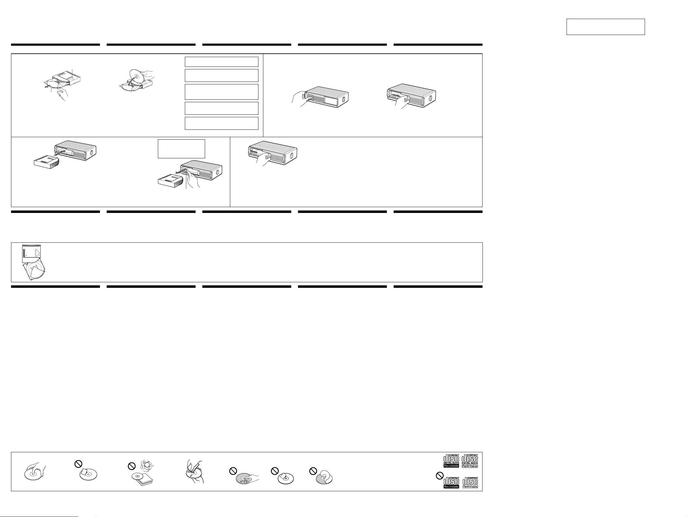
Inserting a disc
With the arrow side facing up
Avec la partie fléchée tournée vers le haut
Mit dem Pfeil nach oben
Met het pijltje naar boven
Con il lato della freccia rivolto verso l’alto
Tab
Languette
Lasche
Lipje
kommen.
Linguetta
When the tray comes out
Normally, the trays will not come out of the magazine. However, if
they are pulled out of the magazine, it is easy to re-insert them.
With the cut-away portion of the tray facing you, insert the right
corner of the tray in the slot, then push in the left corner until it
clicks.
Note
Do not insert the tray upside down or in the wrong direction.
Note
You cannot play an 8cm CD on this unit.
If you use the single adaptor, it may cause a malfunction.
Remarque
Il est impossible de lire un CD de 8 cm sur cet appareil.
Si vous utilisez l’adaptateur unique, il peut provoquer un
dysfonctionnement.
Hinweis
Mit diesem Gerät können Sie keine Single-CDs (8-cm-CDs)
wiedergeben lassen.
Wenn Sie einen Single-CD-Adapter verwenden, kann es zu
Fehlfunktionen
Disc magazine
Chargeur de disques
3
CD-Magazin
Disc-magazijn
Contenitore dischi
If the disc magazine does not lock properly
Take out the magazine, and after pressing the Z (EJECT) button, reinsert it.
Si vous ne pouvez pas fermer le chargeur de disques
Sortez le chargeur et, après avoir appuyé sur la touche Z (EJECT), réinsérez-le.
Wenn sich das CD-Magazin nicht richtig verriegeln läßt
Nehmen Sie das Magazin heraus, drücken Sie die Z (EJECT)-Taste, und setzen Sie das Magazin dann wieder ein.
Als het disc-magazijn niet soepel op zijn plaats vastklikt
Verwijder het disc-magazijn, druk op de Z (EJECT) toets en breng vervolgens het disc-magazijn opnieuw in.
Se il contenitore dischi non si blocca in posizione correttamente
Estrarlo e, dopo aver premuto il tasto Z (EJECT), reinserirlo.
Notes on the disc magazine
• Do not leave the disc magazine in locations with high temperatures and high
humidity such as on a car dashboard or in the rear window where the disc
magazine will be subjected to direct sunlight.
• Do not place more than one disc at a time onto one tray, otherwise the
changer and the discs may be damaged.
• Do not drop the disc magazine or subject it to a violent shock.
Labeled surface up
Etiquette vers le haut
Mit der beschrifteten Seite nach oben
Etiket naar boven
Con l’etichetta rivolta verso l’alto
c
6 discs, one in each tray
6 disques, un par plateau
Insgesamt 6 CDs (eine in jedem Fach)
6 discs, één per lade
6 dischi, uno in ciascun comparto
Opmerking
U kunt geen 8 cm CD afspelen met dit toestel.
Door gebruik te maken van een single adapter kan het
toestel defect raken.
Nota
Con il presente apparecchio, non è possibile riprodurre CD
da 8cm.
Se viene utilizzato l’adattatore singolo, è possibile che si
verifichino problemi di funzionamento.
Remarques sur le chargeur de disques
• Ne pas laisser le chargeur de disques dans un endroit très chaud ou très
humide comme sur le tableau de bord ou sur la plage arrière d’une voiture
où il serait en plein soleil.
• Ne pas insérer plus d’un disque à la fois sur le plateau, sinon le changeur et
les disques risquent d’être endommagés.
• Ne pas laisser tomber le chargeur de disques ni le cogner.
Use the supplied disc magazine or the disc magazine XA-T7.
The disc magazine XA-T6 can not be used with this unit. If you
use any other magazine, it may cause a malfunction.
Utilisez le magasin à disques fourni ou un magasin à disques
XA-T7. Vous ne pouvez pas utiliser de magasin à disques
XA-T6 avec cet appareil. L’utilisation d’un autre type de
magasin à disques risque de provoquer un dysfonctionnement.
Verwenden Sie das mitgelieferte CD-Magazin oder das CDMagazin XA-T7. Das CD-Magazin XA-T6 kann nicht zusammen
mit diesem Gerät eingesetzt werden. Wird ein anderes als das
empfohlene CD-Magazin verwendet, kann es zu
Fehlfunktionen kommen.
Gebruik het meegeleverde disc-magazijn of het disc-magazijn
XA-T7. Het disc-magazijn XA-T6 kan niet met dit toestel
worden gebruikt. Het gebruik van een ander magazijn kan
defecten veroorzaken.
Utilizzare il contenitore dischi in dotazione o il contenitore
dischi XA-T7. Il contenitore dischi XA-T6 non può essere
utilizzato con questo apparecchio. Se si utilizza qualsiasi altro
contenitore, potrebbero sorgere problemi di funzionamento.
To remove
Retrait
Herausnehmen des CD-Magazins
Verwijderen
Per estrarre
Push Z (EJECT) button down
Appuyez sur la touche Z (EJECT)
Drücken Sie die Taste Z (EJECT) nach unten
Druk de Z (EJECT) knop in
Premere il tasto Z (EJECT)
Hinweise zum CD-Magazin
• Halten Sie das Magazin von hohen Temperaturen und Feuchtigkeit fern.
Lassen Sie es nicht auf dem Armaturenbrett, auf der Heckablage usw. liegen,
wo es direktem Sonnenlicht ausgesetzt ist.
• Versuchen Sie nicht, mehr als eine CD in ein Fach einzulegen. Andernfalls
können der Wechsler und die CDs beschädigt werden.
• Lassen Sie das Magazin nicht fallen, und schützen Sie es vor Stößen.
Lorsque le plateau sort
En principe, les plateaux ne sortent pas du chargeur. Toutefois, s’ils
sortent du chargeur, il est facile de les réinsérer.
Avec la portion découpée du plateau vous faisant face, insérer le
coin droit du plateau dans la fente, puis enfoncer le coin gauche
jusqu’au déclic.
Remarque
Ne pas insérer le plateau à l’envers ou dans le mauvais sens.
Een disc inbrengenEinlegen von CDsInsertion d’un disque
21
Push the label printed “PUSH” to unlock the door.
Appuyez sur l’étiquette portant l’inscription “PUSH”
pour déverrouiller la porte.
Drücken Sie auf die mit „PUSH“ gekennzeichnete
Stelle, um den Deckel zu entriegeln.
Druk op het label met de vermelding “PUSH” om de
klep te ontgrendelen.
Per sbloccare il coperchio, premere in corrispondenza
della dicitura “Push”.
Note
To prevent injury, do not insert your hand in the CD changer.
Remarque
Pour éviter toute blessure, ne pas introduire la main dans le changeur de CD.
Hinweis
Um Verletzungen zu vermeiden, greifen Sie mit der Hand nicht in den CDWechsler.
4
Use the unit with the door closed completely
Otherwise, foreign matter may enter the unit and contaminate the
lenses inside the changer.
Note
When a disc magazine is inserted into the CD changer or the reset
button of the connected car audio is pressed, the unit will
automatically be activated and read the information on the CDs.
When the information on all the CDs in the disc magazine has been
read, the unit will automatically stop operation.
Opmerkingen betreffende het disc-magazijn
• Laat het magazijn niet achter op plaatsen waar dit blootgesteld wordt aan
• Steek niet meer dan één enkele disc in een uitsparing, anders kunnen zowel
• Laat het apparaat niet vallen en stel het niet bloot aan hevige trillingen of
Wenn sich ein Fach gelöst hat
Normalerweise können sich die Fächer nicht vom Magazin lösen.
Werden sie jedoch aus dem Magazin herausgezogen, lassen sie sich
mühelos wieder anbringen.
Hierbei muß die Aussparung des Fachs auf Sie weisen. Setzen Sie
dann die rechte Ecke des Fachs in den Einschub ein, und drücken
Sie danach die linke Ecke an, bis das Fach mit einem Klicken
einrastet.
Hinweis
Versuchen Sie nicht, das Fach mit der falschen Seite nach oben oder
verkehrt herum einzusetzen.
c
Utilisez cet appareil avec la fenêtre complètement fermée
Sinon, des corps étrangers pourraient pénétrer dans l’appareil et
encrasser les lentilles dans le lecteur.
Remarque
Quand un chargeur de disques est inséré dans le changeur de CD ou
si la touche de réinitialisation de l’autoradio raccordé est
enclenchée, l’appareil se met automatiquement en marche et
reproduit les CD. Lorsque tous les CD du chargeur ont été
reproduits, l’appareil s’arrête automatiquement.
Verwenden Sie das Gerät nur mit vollständig geschlossener
Klappe
Halten Sie die Klappe des Geräts stets geschlossen, damit keine
Fremdkörper eindringen und die Linsen im Wechsler nicht
verschmutzen können.
Hinweis
Wenn Sie ein CD-Magazin in den CD-Wechsler einsetzen oder die
Rücksetztaste an der angeschlossenen Audio-Anlage in Ihrem Auto
drücken, schaltet sich das Gerät automatisch ein und beginnt, die
Daten auf den CDs zu lesen. Nachdem die Informationen auf allen
CDs im CD-Wechsler gelesen wurden, stoppt das Gerät automatisch.
vocht of aan hoge temperaturen, zoals op het dashboard van een auto of op
de hoedenplank, waar het magazijn in de volle zon staat.
de CD-wisselaar als de compact discs beschadigd worden.
schokken.
Als de houder uitsteekt
Normaal gezien steken de houders niet uit het magazijn. Als ze er toch
zouden zijn uitgetrokken, kan u ze er makkelijk weer insteken.
Met de uitsparing in de houder naar u toe gericht, brengt u de
rechterhoek van de houder in de gleuf en drukt dan de linkerhoek
erin tot u een klik hoort.
Opmerking
De houder niet omgekeerd of in de verkeerde richting inbrengen.
Inserimento di un disco
Slide open
Coulissez pour ouvrir
Öffnen
Openschuiven
Aprire facendo scorrere lo sportello
Opmerking
Steek uw hand niet in de CD-wisselaar om verwondingen te voorkomen.
Nota
Per evitare danni alla persona, non inserire le mani nel cambia CD.
Gebruik het toestel met volledig gesloten klep
Anders zou er stof of vuil in het apparaat terecht kunnen komen,
met als gevolg vervuilde lenzen en storingen in de werking.
Opmerking
Wanneer een disc-magazijn in de compact disc-wisselaar wordt
geplaatst of de terugsteltoets van de uitleesvenster-eenheid wordt
ingedrukt, zal het apparaat automatisch ingeschakeld worden,
waarna de informatie van de compact discs gelezen wordt. Nadat
alle informatie gelezen is, zal het apparaat weer automatisch in de
stopstand komen te staan.
Utilizzare l’apparecchio con lo sportello chiuso
Diversamente oggetti estranei potrebbero penetrare
nell’apparecchio e contaminare le lenti all’interno del cambia CD.
Nota
Quando un contenitore dischi è inserito nel cambia CD o viene
premuto il pulsante di azzeramento dell’autostereo collegato,
l’apparecchio si accende automaticamente e legge le informazioni
dei dischi. Quando le informazioni di tutti i dischi inseriti nel
contenitore dischi sono state lette, l’apparecchio si ferma
automaticamente .
Note sul contenitore dischi
• Non lasciare il contenitore dischi in luoghi con temperature elevate o molto
umidi, come sul cruscotto o sul ripiano posteriore di un’auto dove il
contenitore potrebbe essere esposto alla luce solare diretta.
• Non inserire più di un disco alla volta in ciascun comparto, diversamente il
cambia CD e i dischi saranno danneggiati.
• Non lasciar cadere il contenitore dischi e non sottoporlo a urti violenti.
Quando il comparto fuoriesce
Di solito, i comparti non fuoriescono dal contenitore; se ciò dovesse
avvenire, è facile reinserirli.
Con la parte del comparto tagliata rivolta in avanti, inserire
l’angolo destro del comparto nell’alloggiamento, quindi inserire
l’angolo sinistro fino a farlo scattare in posizione.
Nota
Non inserire il vassoio capovolto o nella direzione errata.
Notes on handling discs
A dirty or defective disc may cause sound drop-outs during playback. To
enjoy optimum sound, handle the disc as follows.
• Handle the disc by its edge, and to keep the disc clean, do not touch the
unlabeled surface. (fig. A)
• Do not stick paper or tape on the disc. (fig. B)
• Keep your discs in their cases or disc magazines when not in use.
Do not expose discs to direct sunlight or heat sources such as hot airducts. Do not leave discs in a car parked in direct sunlight where there
can be a considerable rise in the temperature inside the car. (fig. C)
• Before playing, clean the discs with a commercially available cleaning
cloth. Wipe each disc from the centre out. (fig. D)
Do not use solvents such as benzine, thinner, commercially available
cleaners, or antistatic spray intended for analog discs.
• Discs with non-standard shapes (e.g., heart, square, star) cannot be
played on this unit. Attempting to do so may damage the unit. Do not
use such discs.
• You cannot play 8cm CDs.
Notes on discs
If you use the discs explained below, the sticky residue can cause the disc to
stop spinning and may cause malfunction or ruin your discs.
Do not use second-hand or rental CDs that have a sticky residue on the surface
(for example from peeled-off stickers or from ink, or glue leaking from under
the stickers).
• There are paste residue. Ink is sticky. (fig. E)
Do not use rental CDs with old labels that are beginning to peel off.
• Stickers that are beginning to peel away, leaving a sticky residue.
(fig. F)
Do not use your discs with labels or stickers attached.
• Labels are attached. (fig. G)
Do not use any discs with labels or stickers attached.
The following malfunctions may result from using such discs:
• Inability to eject a disc (due to a label or sticker peeling off and jamming the
eject mechanism).
• Inability to read audio data correctly (e.g., playback skipping, or no
playback) due to heat shrinking of a sticker or label causing a disc to warp.
• Damage to other discs in a disc magazine.
Notes on CD-R/CD-RW discs
• You can play CD-Rs/CD-RWs (recordable CDs/rewritable CDs) designed
for audio use on this unit. (fig. H)
• Some CD-Rs/CD-RWs (depending on the equipment used for its
recording or the condition of the disc) may not play on this unit.
• You cannot play a CD-R/CD-RW that is not finalized*.
* A process necessary for a recorded CD-R/CD-RW disc to be played on the audio
CD player.
Remarques sur la manipulation des disques
Un disque sale ou défectueux peut provoquer des pertes de son à la lecture.
Manipuler le disque comme suit pour obtenir un son optimal.
• Manipuler le disque par son arête et le maintenir dans un état propre,
ne pas le toucher sur la surface non imprimée. (fig. A)
• Ne pas coller de papier ou de bande adhésive sur le disque. (fig. B)
• Conservez vos disques dans leurs boîtiers ou des pochettes de
rangement lorsqu’ils ne sont pas utilisés.
Ne pas laisser les disques en plein soleil ou près d’une source de chaleur
comme des conduits d’air chaud. Ne pas laisser les disques dans une
voiture garée en plein soleil car la température de l’habitacle risque
d’augmenter considérablement. (fig. C)
• Avant la lecture, nettoyez les disques avec un chiffon de nettoyage
disponible dans le commerce. Essuyez chaque disque en partant du
centre vers l’extérieur. (fig. D)
N’utilisez pas de solvants tels que la benzine, du diluant, des produits de
nettoyage vendus dans le commerce ou des sprays antistatiques destinés aux
disques analogiques.
• Les disques de formes non standard (par exemple en forme de cœur, de
carré ou d’étoile) ne peuvent pas être lus sur cet appareil. Vous risquez
d’endommager votre appareil si vous essayez de le faire. N’utilisez pas
de tels disques.
• La lecture de CD de 8 cm n’est pas possible.
Remarques sur les disques
Si vous utilisez les disques décrits ci-dessous, le résidu adhésif risque de
provoquer l’arrêt de la rotation du disque et d’entraîner un
dysfonctionnement ou d’endommager vos disques.
N’utilisez pas de CD de seconde main ou de location qui présentent des
résidus adhésifs à la surface (par exemple d’étiquettes décollées ou d’encre, de
colle dépassant de l’étiquette).
• Résidus de colle. L’encre colle. (fig. E)
N’utilisez pas de CD de location avec d’anciennes étiquettes qui
commencent à se décoller.
• Les étiquettes qui commencent à se décoller laissent des résidus
adhésifs. (fig. F)
N’utilisez pas vos disques avec des étiquettes ou des autocollants apposés
dessus.
• Les étiquettes sont fixées. (fig. G)
N’utilisez pas de disques comportant des étiquettes ou
des autocollants.
Dans le cas contraire, les dysfonctionnements suivants peuvent se produire :
• Impossible d’éjecter un disque (à cause d’une étiquette ou d’un autocollant
qui se décolle et qui bloque le mécanisme d’éjection)
• Impossible de lire des données audio correctement (par ex. : saut de lecture
ou pas de lecture), le disque est voilé en raison du rétrécissement d’un
autocollant ou d'une étiquette sous l’effet de la chaleur
• Endommagement des autres disques dans un chargeur
Remarques sur les disques CD-R/CD-RW
• Vous pouvez écouter avec cet appareil des CD-R/CD-RW (CD
enregistrables/CD réinscriptibles) conçus pour une utilisation audio.
(fig. H)
• Certains CD-R/CD-RW (en fonction des conditions de l’équipement
d’enregistrement ou du disque) risquent de ne pas être lus avec cet
appareil.
• Vous ne pouvez pas lire de disques CD-R/CD-RW non finalisés*.
* Un processus nécessaire à la lecture des disques CD-R/CD-RW enregistrés sur le
lecteur de CD audio.
Hinweise zum Umgang mit CDs
Eine verschmutzte oder beschädigte CD kann Tonaussetzer verursachen. Um
optimale Klangqualität sicherzustellen, beachten Sie folgendes:
• Damit die CD sauber bleibt, fassen Sie sie immer am Rand an, und
berühren Sie nicht die Seite ohne Beschriftung. (Abb. A)
• Kleben Sie weder Papier noch Klebeband auf die CD. (Abb. B)
• Bewahren Sie CDs in ihrer Hülle oder in den CD-Magazinen auf, wenn
sie nicht abgespielt werden.
Schützen Sie die CD vor Sonnenlicht und Wärmequellen wie
Warmluftauslässen. Lassen Sie sie nicht in einem Auto liegen, das direkt
in der Sonne geparkt ist, da die Temperatur im Wageninneren sehr hoch
ansteigen kann. (Abb. C)
• Reinigen Sie die CDs vor dem Abspielen mit einem handelsüblichen
Reinigungstuch. Wischen Sie dabei von der Mitte nach außen. (Abb. D)
Verwenden Sie keine Lösungsmittel wie Benzin oder Verdünner und keine
handelsüblichen Reinigungsmittel oder Antistatik-Sprays für Schallplatten.
• CDs mit ungewöhnlichen Formen, zum Beispiel herz- oder sternförmige
oder quadratische CDs, können Sie mit diesem Gerät nicht abspielen.
Falls Sie es doch versuchen, kann das Gerät beschädigt werden.
Verwenden Sie solche CDs nicht.
• Single-CDs (8-cm-CDs) können nicht wiedergegeben werden.
Hinweise zu CDs
Wenn Sie die unten aufgeführten CDs verwenden, können
Klebstoffrückstände dazu führen, daß die CD sich nicht mehr dreht, oder
Fehlfunktionen oder Schäden an der CD verursachen.
Verwenden Sie keine gebraucht gekauften oder Leih-CDs mit klebrigen
Rückständen auf der Oberfläche (z. B. von abgelösten Aufklebern, von Tinte
oder von Klebstoff, der unter den Aufklebern hervorquillt).
• Klebstoffrückstände. Tinte klebt. (Abb. E)
Verwenden Sie keine Leih-CDs mit alten Etiketten, die sich abzulösen
beginnen.
• Aufkleber, die sich zu lösen beginnen und Klebstoffrückstände
hinterlassen. (Abb. F)
Verwenden Sie keine CDs, an denen Etiketten oder Aufkleber angebracht
sind.
• Angebrachte Etiketten. (Abb. G)
Verwenden Sie keine CDs, an denen Etiketten oder
Aufkleber angebracht sind.
Bei Verwendung solcher CDs kann es zu folgenden Fehlfunktionen kommen:
• Die CD läßt sich nicht auswerfen, weil sich ein Etikett oder Aufkleber geläst
hat und den Auswurfmechanismus blockiert.
• Die Audiodaten werden nicht korrekt gelesen (z.B.Tonspränge bei der
Wiedergabe, keine Wiedergabe), weil ein Etikett oder Aufkleber durch
Wärmeeinwirkung geschrumpft ist und die CD sich verzogen hat.
• Die anderen CDs in einem CD-Magazin werden beschädigt.
Hinweise zu CD-Rs/CD-RWs
• Mit diesem Gerät können Sie CD-Rs/CD-RWs (beschreibbare CDs/
wiederbeschreibbare CDs) wiedergeben lassen, die für den Einsatz als
Tondatenträger konzipiert sind. (Abb. H)
• Je nach dem Aufnahmegerät, mit dem die CD-R/CD-RW bespielt wurde,
oder dem Zustand der CD-R/CD-RW selbst können einige CD-Rs/CD-RWs
mit diesem Gerät möglicherweise nicht wiedergegeben werden.
• Eine noch nicht abgeschlossene CD-R/CD-RW kann nicht wiedergegeben
werden*.
* Damit eine bespielte CD-R/CD-RW auf einem Audio-CD-Player wiedergegeben
werden kann, ist ein spezieller Prozeß erforderlich.
Opmerkingen bij het omgaan met discs
Bij het afspelen van een vuile of beschadigde disc kan het geluid regelmatig
wegvallen. Voor het verzekeren van een goede geluidsweergave dient u als
volgt met discs om te gaan.
• Pak een compact disc altijd bij de rand vast, houd hem proper en raak
• Plak geen papier of plakband op een compact disc. (afb. B)
• Bewaar uw discs in hun doosje of disc-magazijn wanneer u ze niet
• Maak een disc voor het afspelen altijd schoon met een in de handel
• Discs met afwijkende vormen (b.v. hart, vierkant, ster) kunnen niet met
• U kunt geen 8cm CD’s afspelen.
Opmerkingen bij discs
Indien u de discs behandelt zoals hieronder beschreven, kunnen kleverige
resten de disc doen stoppen waardoor het toestel defect of uw discs
beschadigd kunnen raken.
Gebruik geen gebruikte of gehuurde CD’s met kleverig oppervlak
(bijvoorbeeld afkomstig van stickers of inkt of lijm die van onder de stickers
komt).
• Lijmresten. Kleverige inkt. (afb. E)
• Stickers die loskomen laten kleverige resten achter. (afb. F)
• Vastgekleefde labels. (afb. G)
Gebruik geen discs waarop stickers zijn gekleefd.
Indien dergelijke discs toch worden gebruikt, kan dat leiden tot:
• het niet uitwerpen van een disc (doordat een sticker losraakt en het
• het niet correct uitlezen van audiogegevens (b.v. geluid verspringt of wordt
• beschadiging van andere discs in een discmagazijn.
Opmerkingen bij CD-R/CD-RW discs
• Audio CD-R’s/CD-RW’s (opneembare CD’s/herschrijfbare CD’s) kunnen
• Sommige CD-R’s/CD-RW’s (afhankelijk van de opname-apparatuur of de
• U kunt geen CD-R/CD-RW afspelen die niet is gefinaliseerd*.
* Proces dat nodig is om een opgenomen CD-R/CD-RW disc af te spelen met een
A GBC DEF
This way
Oui
Richtig
Juist
Cosi
Not this way
Non
Falsch
Fout
Non cosi
Not this way
Non
Falsch
Fout
Non cosi
This way
Oui
Richtig
Juist
Cosi
het oppervlak (behalve het label) niet aan. (afb. A)
gebruikt.
Stel compact discs niet bloot aan direkt zonlicht of warmeluchtkanalen.
Laat ze niet liggen in een geparkeerde auto in de volle zon, aangezien
de temperatuur hierin bijzonder hoog kan oplopen. (afb. C)
verkrijgbare doek. Wrijf van binnen naar buiten toe. (afb. D)
Gebruik geen solventen zoals benzine, thinner en in de handel verkrijgbare
reinigingsmiddelen of antistatische sprays voor grammofoonplaten.
deze dit toestel worden afgespeeld. Indien u dat toch doet, kan het
toestel worden beschadigd. Gebruik geen dergelijke discs.
Gebruik geen gehuurde CD’s met oude labels die loskomen.
Gebruik geen discs waarop stickers zijn gekleefd.
uitwerpmechanisme blokkeert);
niet weergegeven) doordat de sticker onder invloed van de warmte krimpt
en de disc kromtrekt;
met dit toestel worden afgespeeld. (fig. H)
staat van de disc) kunnen niet met dit toestel worden afgespeeld.
CD-speler.
Look for this mark to distinguish CD-Rs/CD-RWs for audio use.
H
Ce symbole permet de distinguer les CD-R/CD-RW conçus pour une utilisation audio.
Für den Einsatz als Tondatenträger konzipierte CD-Rs/CD-RWs sind mit dieser
Markierung gekennzeichnet.
Audio CD-R’s/CD-RW’s zijn hieraan te herkennen.
Ricercare questo simbolo per distinguere i CD-R/CD-RW per utilizzo audio.
This mark denotes that a disc is not for audio use.
Ce symbole indique qu’un disque n’est pas conçu pour une utilisation audio.
Nicht für den Einsatz als Tondatenträger geeignete CD-Rs/CD-RWs sind mit
dieser Markierung gekennzeichnet.
Dit geeft aan dat een disc niet geschikt is voor audiotoepassingen.
Questo simbolo indica che il disco non è destinato all’utilizzo audio.
Note sulla manipolazione dei dischi
Un disco sporco o difettoso può causare cadute di suono durante la
riproduzione. Per poter ascoltare un suono ottimale, trattare i dischi come
indicato.
• Prendere i dischi per il bordo e, per tenerli puliti, non toccare la
superficie senza etichetta. (fig. A)
• Non attaccare carta o nastro adesivo sul disco. (fig. B)
• Quando non vengono utilizzati, conservare i dischi nelle apposite
custodie.
Non esporre i dischi alla luce solare diretta o a fonti di calore come
condotti di aria calda. Non lasciarli in veicoli parcheggiati al sole dove
può verificarsi un considerevole aumento della temperatura. (fig. C)
• Prima della riproduzione, pulire i CD con un panno di pulizia disponibile
in commercio. Pulire ogni CD dal centro verso l’esterno. (fig. D)
Non utilizzare solventi quali benzene, acquaragia o detersivi reperibili in
commercio, né spray antistatici per dischi analogici.
• Non è possibile riprodurre CD con forme irregolari (ad esempio a forma
di cuore, di quadrato, di stella) su questo lettore. Non utilizzare tali
dischi onde evitare di danneggiare il lettore.
• Non è possibile riprodurre CD da 8 cm.
Note sui dischi
I residui di colla presenti sui dischi indicati di seguito potrebbero causare
l’arresto del disco stesso e problemi di funzionamento dell’apparecchio o
danneggiare i dischi stessi.
Non utilizzare dischi di seconda mano o presi a noleggio che presentano
residui di colla sulla superficie, ad esempio residui di etichette o inchiostro
rimossi oppure residui di colla che fuoriescono dalle etichette.
• Residui di colla. Residui di inchiostro. (fig. E)
Non utilizzare dischi presi a noleggio con etichette vecchie che cominciano a
staccarsi.
• Etichette che cominciano a staccarsi, lasciando residui di colla. (fig. F)
Non utilizzare dischi su cui siano applicati etichette o adesivi.
• Etichette applicate. (fig. G)
Non utilizzare dischi su cui sono applicate etichette o
adesivi.
Se vengono utilizzati tali tipi di disco, potrebbero verificarsi i seguenti
problemi di funzionamento:
• Non è possibile espellere il disco (a causa di un’etichetta o di un adesivo
sporgente che inceppa il meccanismo di espulsione)
• Non è possibile leggere i dati audio in modo corretto (ad esempio, la
riproduzione salta o non funziona) a causa del restringimento per
surriscaldamento di un adesivo o di un’etichetta che può deformare il disco
• È possibile che all’interno di un contenitore di dischi vengano danneggiati
altri dischi
Note sui CD-R/CD-RW
• Con il presente apparecchio è possibile riprodurre CD-R/CD-RW (CD
registrabili/CD riscrivibili) progettati per l’utilizzo audio. (fig. H)
• In base alle condizioni dell’apparecchio di registrazione o del CD-R/CDRW stesso, alcuni CD-R/CD-RW potrebbero non essere riprodotti su
questo apparecchio.
• Non è possibile riprodurre CD-R/CD-RW non finalizzati*.
* Operazione necessaria per la riproduzione su lettore CD audio di un CD-R/CD-
RW registrato.
44
Page 5
CDX-T69/T69X
Installation
Precautions
• Choose the mounting location carefully, observing the
following:
— The unit is not subject to temperatures exceeding 55°C
(131°F) (such as in a car parked in direct sunlight).
— The unit is not subject to direct sunlight.
— The unit is not near heat sources (such as heaters).
— The unit is not exposed to rain or moisture.
— The unit is not exposed to excessive dust or dirt.
— The unit is not subject to excessive vibration.
— The fuel tank should not be damaged by the tapping
screws.
— There should be no wire harnesses or pipes under the
place where you are going to install the unit.
— The spare tire, tools or other equipment in or under the
trunk should not be interfered with or damaged by the
screws or the unit itself.
• Be sure to use only the supplied mounting hardware for a
safe and secure installation.
• Use only the supplied screws.
• Make holes of ø 3.5 mm (5/32 in.) only after making sure
there is nothing on the other side of the mounting surface.
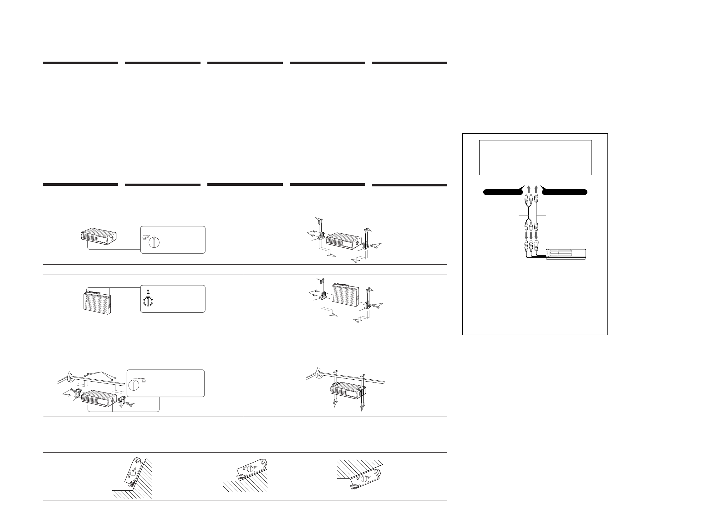
How to install the unit
Horizontal installation
Installation Installation InstallazioneInstalleren
Précautions
• Choisissez l’emplacement de montage en tenant compte
des observations suivantes :
— L’appareil ne doit pas être exposé à des températures
supérieures à 55°C (comme dans une voiture garée en
plein soleil).
— L’appareil ne doit pas être utilisé en plein soleil.
— L’appareil ne doit pas être utilisé près d’une source de
chaleur (comme un chauffage).
— L’appareil ne doit pas être utilisé dans un endroit
exposé à la pluie ou à l’humidité.
— L’appareil ne doit pas être utilisé dans un
endroitpoussiéreux ou sale.
— L’appareil ne doit pas être exposé à des vibrations
excessives.
— Vérifiez que le réservoir d’essence ne risque pas d’être
endommagé par les vis taraudeuses.
— Il ne doit pas y avoir de faisceau de fils ou de tuyaux à
l’emplacement du montage.
— Vérifiez que l’appareil ou les vis ne risquent pas
d’endommager ou de gêner la roue de secours, les
outils, ou tout autre objet dans le coffre.
• Pour garantir la sécurité de l’installation, utiliser
uniquement le matériel de montage fourni.
• Utilisez uniquement les vis fournies.
• Ne percez les trous de 3,5 mm de diamètre qu’après vous
être assuré qu’il n’y avait rien de l’autre côté de la surface
de montage.
Installation de l’appareil
Installation horizontale
Sicherheitsmaßnahmen
• Bei der Wahl des Einbauortes ist folgendes zu beachten:
— Das Gerät darf keinen Temperaturen über 55 °C
ausgesetzt sein, wie sie z. B. in einem in der Sonne
geparkten Fahrzeug auftreten können.
— Das Gerät darf keiner direkten Sonneneinstrahlung
ausgesetzt sein.
— Das Gerät muß von Wärmequellen (z. B. der Heizung)
ferngehalten werden.
— Das Gerät darf weder Regen noch Feuchtigkeit
ausgesetzt sein.
— Das Gerät darf keinem übermäßigen Staub oder
anderer Verschmutzung ausgesetzt sein.
— Das Gerät darf keinen übermäßigen Vibrationen
ausgesetzt sein.
— Der Tank darf durch die Schneidschrauben nicht
beschädigt werden.
— Unter der Fläche, auf die das Gerät montiert werden
soll, dürfen sich keine Kabelbäume oder Leitungen
befinden.
— Ersatzreifen, Werkzeug usw. im oder unter dem
Kofferraum dürfen durch die Schneidschrauben nicht
beschädigt werden. Achten Sie auch darauf, daß die
Herausnahme des Ersatzreifens, Werkzeugs usw. nicht
durch das Gerät behindert wird.
• Für sicheren und stabilen Einbau verwenden Sie
ausschließlich die mitgelieferten Befestigungsteile.
• Verwenden Sie ausschließlich die mitgelieferten
Schrauben.
• Bohren Sie die Löcher mit einem Durchmesser von 3,5 mm
erst, wenn Sie sich vergewissert haben, daß sich nichts auf
der Rückseite der Montagefläche befindet.
Installation des Gerätes
Horizontaler Einbau
1 2
Align with the marked position.
Aligner sur le repère.
Auf die richtige Position stellen.
Stel aldus in op het merkteken.
Allineare con il punto segnato.
Vertical installation
1
Align with the marked position.
Aligner sur le repère.
VERTICAL
Auf die richtige Position stellen.
Stel aldus in op het merkteken.
Allineare con il punto segnato.
Suspended installation
When the unit is to be installed under the rear tray
etc. in the trunk compartment, make sure the
following provisions are made.
• Choose the mounting location carefully so that the unit can
be installed horizontally.
• Make sure the unit does not hinder the movement of the
torsion bar spring etc. of the trunk lid.
1
ø 3.5 mm (5/32 in.)
Installation suspendue
Si l’appareil doit être installé sous la plage arrière
dans le coffre par exemple, observer les précautions
suivantes.
• Choisissez l’emplacement pour pouvoir installer l’appareil
à l’horizontale.
• Vérifiez que l’appareil ne gêne pas les mouvements du
ressort de fermeture du coffre, entre autres.
Align with the marked position.
Aligner sur le repère.
Auf die richtige Position stellen.
Stel aldus in op het merkteken.
Allineare con il punto segnato.
Hängender Einbau
Bei hängender Installation unter der Heckablage
usw. im Kofferraum beachten Sie folgende
Vorsichtsmaßnahmen:
• Wählen Sie den Befestigungsort sorgfältig so aus, daß das
Gerät horizontal montiert werden kann.
• Achten Sie darauf, daß das Gerät die
Heckklappendämpfer usw. nicht behindert.
Connections/Connexions/
Anschluß/Aansluitingen/
Voorzorgsmaatregelen
• Kies de plaats van opstelling met zorg, zodat het toestel
niet:
— Onderhevig is aan temperaturen boven de 55°C (zoals
in een auto geparkeerd in de volle zon).
— Steeds blootgesteld wordt aan direkt zonlicht.
— Te dicht bij een warmtebron komt (zoals een
autoverwarming).
— Nat kan worden, door regen, vocht of opspattend
water.
— In kontakt komt met veel stof of vuil.
— Onderhevig is aan sterke trillingen of schokken.
— Let op dat de plaatschroeven de benzinetank niet
beschadigen.
— Kontroleer of onder de plaats waar u het apparaat wilt
monteren geen bedrading of leidingen lopen.
— Houd bij het monteren rekening met het reservewiel,
gereedschappen en-eventueel in de kofferruimte
aanwezige andere apparaten, zodat deze de compact
disc wisselaar niet in de weg zitten, noch beschadigd
kunnen worden door de montageschroeven van de
laatste.
• In het belang van een veilige en stevige montage dient u
uitsluitend het bijgeleverde montagemateriaal te
gebruiken.
• Gebruik enkel de meegeleverde schroeven.
• Controleer of er niets achter het bevestigingsvlak zit en
maak pas dan gaten van 3,5 mm diameter.
Installatie van het apparaat
Horizontaal installeren
ø 3.5 mm
(5/32 in.)
Vertikaal installeren Installazione in verticaleVertikaler EinbauInstallation verticale
2
ø 3.5 mm
(5/32 in.)
Hangend installeren
Als u het apparaat onder de hoedenplank of iets
dergelijks wilt installeren, let dan op de volgende
punten:
• Kies een geschikte plek waar u het apparaat horizontaal
kunt ophangen.
• Vergewis u ervan dat het apparaat niet beschadigd kan
worden door bewegende onderdelen zoals een
kofferdeksel, de veren van de vijfde deur, enz.
2
Precauzioni
• Scegliere con cura il luogo di installazione, seguendo le
istruzioni riportate di seguito ed evitando di installare
l’apparecchio in luoghi:
— Soggetti a temperature oltre i 55°C (come in un’auto
parcheggiata al sole).
— Esposti alla luce solare diretta.
— Vicini a fonti di calore (come impianti di
riscaldamento).
— Esposti alla pioggia o all’umidità.
— Esposti a polvere o sporco eccessivi.
— Soggetti a vibrazioni eccessive.
— Il serbatoio del carburante non deve essere danneggiato
dalle viti filettanti.
— Non devono essere presenti né cavi né tubi sotto il
luogo scelto per l’installazione dell’apparecchio.
— Le viti e l’apparecchio stesso non devono interferire
con, o danneggiare, la ruota di scorta, gli attrezzi o altri
dispositivi presenti dentro o sotto il bagagliaio.
• Assicurarsi di usare solo il materiale di montaggio in
dotazione per un’installazione stabile e sicura.
• Utilizzare solo le viti in dotazione.
• Assicurarsi che non vi sia nulla sull’altro lato della
superficie di montaggio, quindi effettuare fori di solo 3,5
mm di diametro.
Installazione dell’apparecchio
Installazione in orizzontale
Installazione in sospensione
Se l’apparecchio deve essere installato sotto il ripiano
posteriore, nel bagagliaio, ecc., assicurarsi di
prendere le seguenti precauzioni:
• Scegliere con attenzione il luogo di montaggio in modo
che l’apparecchio possa essere installato orizzontalmente.
• Assicurarsi che l’apparecchio non ostacoli il movimento
della molla della barra di torsione ecc. del coperchio del
cofano.
Collegamenti
For details, refer to the Installation/Connections manual of each product.
Pour plus de détails, consulter le manuel d’installation/connexions de chaque produit.
Einzelheiten entnehmen Sie der Installations-/Anschlußanleitung des betreffenden Geräts.
Zie voor nadere bijzonderheden de gebruiksaanwijzing voor installatie en aansluitingen
van de aan te sluiten apparatuur.
Per i dettagli, fare riferimento al manuale di installazione/collegamenti dell’autoradio.
Connection diagram/Schéma de connexion/Anschlußdiagramm/
Aansluitingsschema/Schema di collegamento
To the car audio (the master unit) compatible with the Sony Bus or the source selector
Vers le système audio voiture (appareil principal) compatible avec le bus Sony ou le
sélecteur de source.
an Autoanlage (Hauptgerät), die mit dem Sony-Bus oder dem Signalquellenwähler
kompatibel ist
Op het car audiosysteem (hoofdtoestel) dat compatibel is met Sony Bus of de
bronkeuzeschakelaar
All’autoradio (unità principale) compatibile con bus Sony o con il selettore di
sorgente.
BUS AUDIO IN BUS CONTROL IN
45
CDX-T69/T69X
Note
For connecting two or more changers, the XA-C30 source selector (optional) is necessary.
Remarque
Pour raccorder deux ou plusieurs changeurs, le sélecteur de source XA-C30 (en option) est nécessaire.
Hinweis
Zum Anschließen von zwei oder mehr Wechslern wird der gesondert erhältliche Signalquellenwähler
XA-C30 benötigt.
Opmerking
Om twee of meer wisselaars aan te sluiten is de optionele geluidsbronkiezer XA-C30 vereist.
Nota
Per collegare uno o più cambia CD, è necessario il selettore di fonte XA-C30 (opzionale).
Inclined installation
After installing the unit, align the dials with one of
the marks so that the arrows are as vertical as
possible.
Note
Be sure to align the left and right dials with the same
mark.
Installation inclinée
Après avoir installé l’appareil, alignez le disque sur
l’un des repères afin que la flèche soit aussi proche
que possible de la position verticale.
Remarque
Veillez à aligner les disques gauche et droite sur le même
repère.
Installation in geneigter Position
Nach dem Installieren des Geräts richten Sie die
Dial-Ringe an einer der Markierungen aus, so daß
der Pfeil möglichst senkrecht steht.
Hinweis
Achten Sie darauf, den linken und rechten Dial-Ring an
derselben Markierung auszurichten.
Niet-horizontale plaatsing
Zodra de eenheid geplaatst is, draait u de ringen op
een stand waarbij de pijl zoveel mogelijk in een
vertikale positie staat.
Opmerking
Zet de linker-en de rechterring op dezelfde stand.
Installazione in posizione inclinata
Dopo aver installato l’apparecchio, allineare le
manopole ad una delle tacche in modo che la freccia
sia il più verticale possibile.
Nota
Accertarsi di allineare le manopole di sinistra e di destra
alla stessa tacca.
55
Page 6
CDX-T69/T69X
)
SECTION 2
DISASSEMBLY
• This set can be disassembled in the order shown below.
2-1. DISASSEMBLY FLOW
Note 1: The process described in can be performed in any order.
Note 2: Without completing the process described in , the next process can not be performed.
SET
2-2. FRONT PANEL (S) ASSY, CASE (UPPER S)
(Page 6)
2-3. MECHANISM DECK (MG-276A-159)
(Page 6)
2-4. JACK BOARD
(Page 7)
2-5. BELT (TS)
(Page 7)
2-6. MAIN BOARD
(Page 8)
2-7. ESCUTCHEON (S),
SLIDE VARIABLE RESISTOR
(ELEVATOR HEIGHT SENSOR)
(RV301)
(Page 8)
2-8. MD MOTOR ASSY
(ELEVATOR)
(M104)
(Page 9)
2-9. LE MOTOR ASSY
(CHUCKING)
(M103)
(Page 9)
2-10. RF BOARD
(Page 10)
2-11. SLED MOTOR
COMPLETE ASSY
(M101)
(Page 10)
2-12. OPTICAL PICK-UP
(KSS-720A)
(Page 11)
Note: Follow the disassembly procedure in the numerical order given.
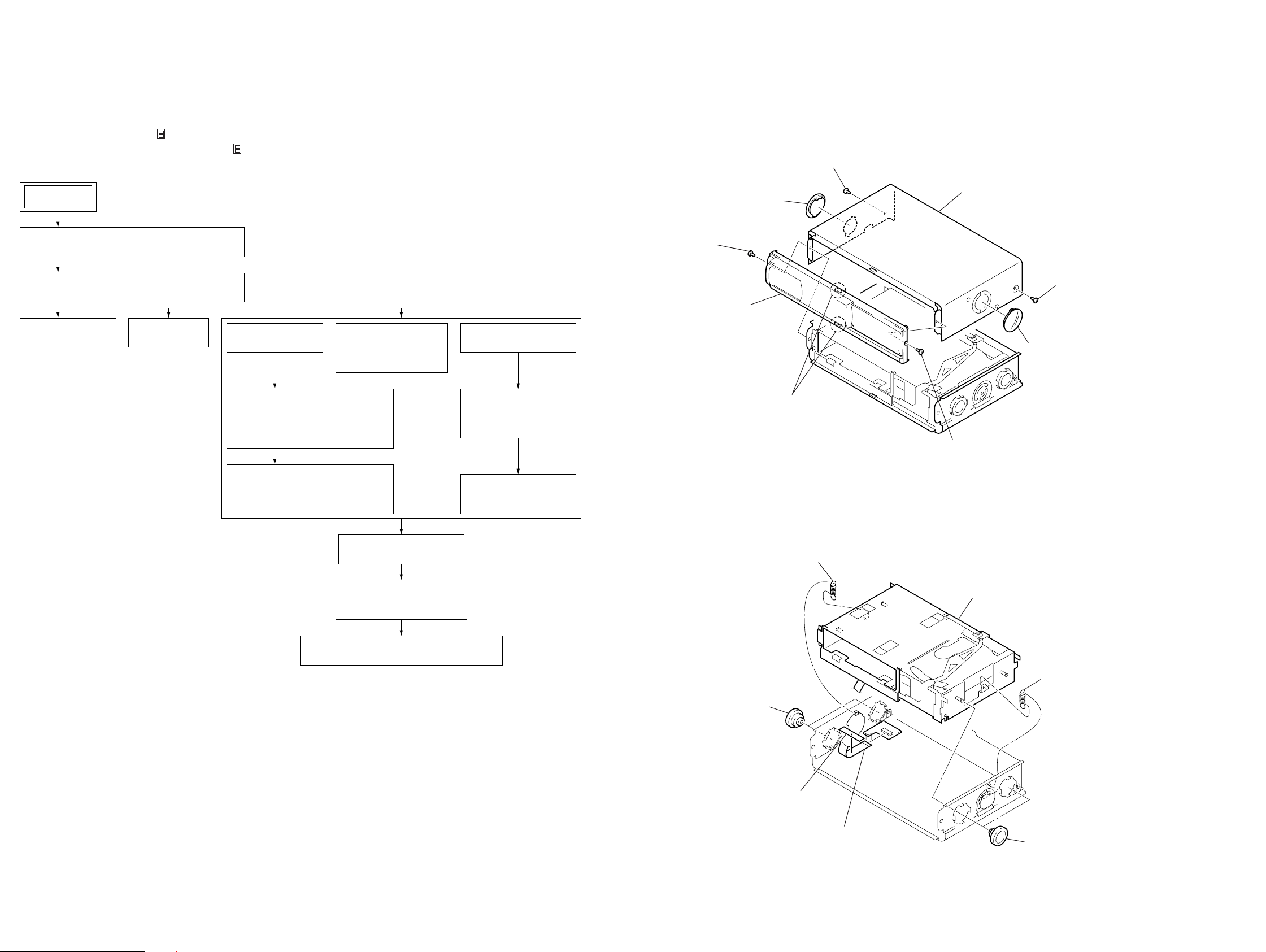
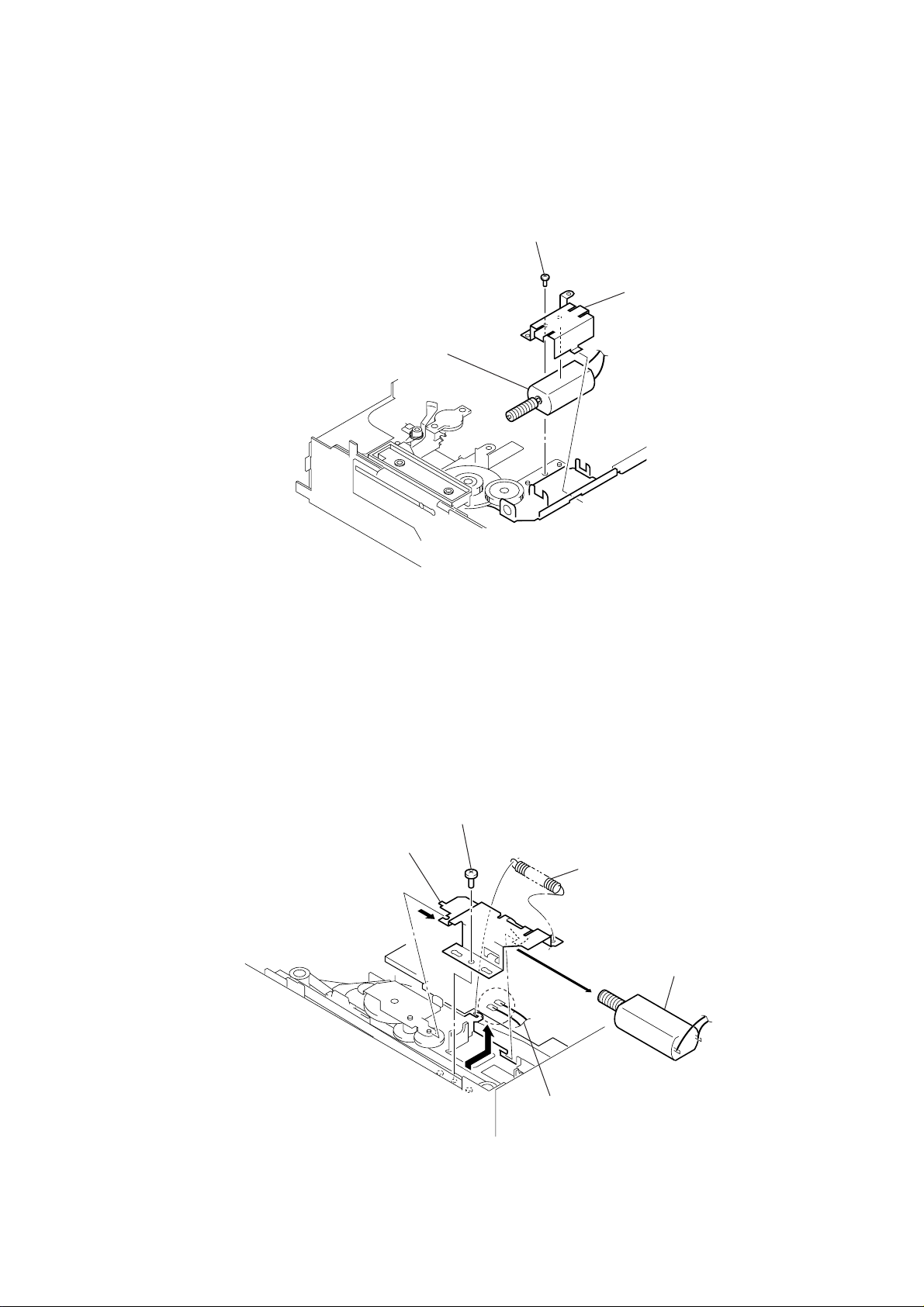
2-2. FRONT PANEL (S) ASSY, CASE (UPPER S)
4
screw
1
screw
(PTT2.6
3
×
front panel (S) assy
6
lever (FLT. 838)
6)
2
two claws
(PTT2.6
×
6)
2-3. MECHANISM DECK (MG-276A-159)
5
case (upper S)
1
screw
(PTT2.6
4
screw
(PTT2.6
6
lever (FLT. 838)
×
6)
×
6
2-13. CHASSIS (EV) ASSY
(Page 11)
2-14. LEVER (CHK.L) ASSY,
LEVER (CHK.R) ASSY
(Page 12)
2-15. CHASSIS (OP) BLOCK SERVICE ASSY
(Page 12)
1
two dampers (S)
2
spring (FLT. S)
filament tape
3
jack flexible board
(CN901)
4
mechanism deck (MG-276A-159)
2
spring (FLT. S)
1
two dampers (S)
66
Page 7
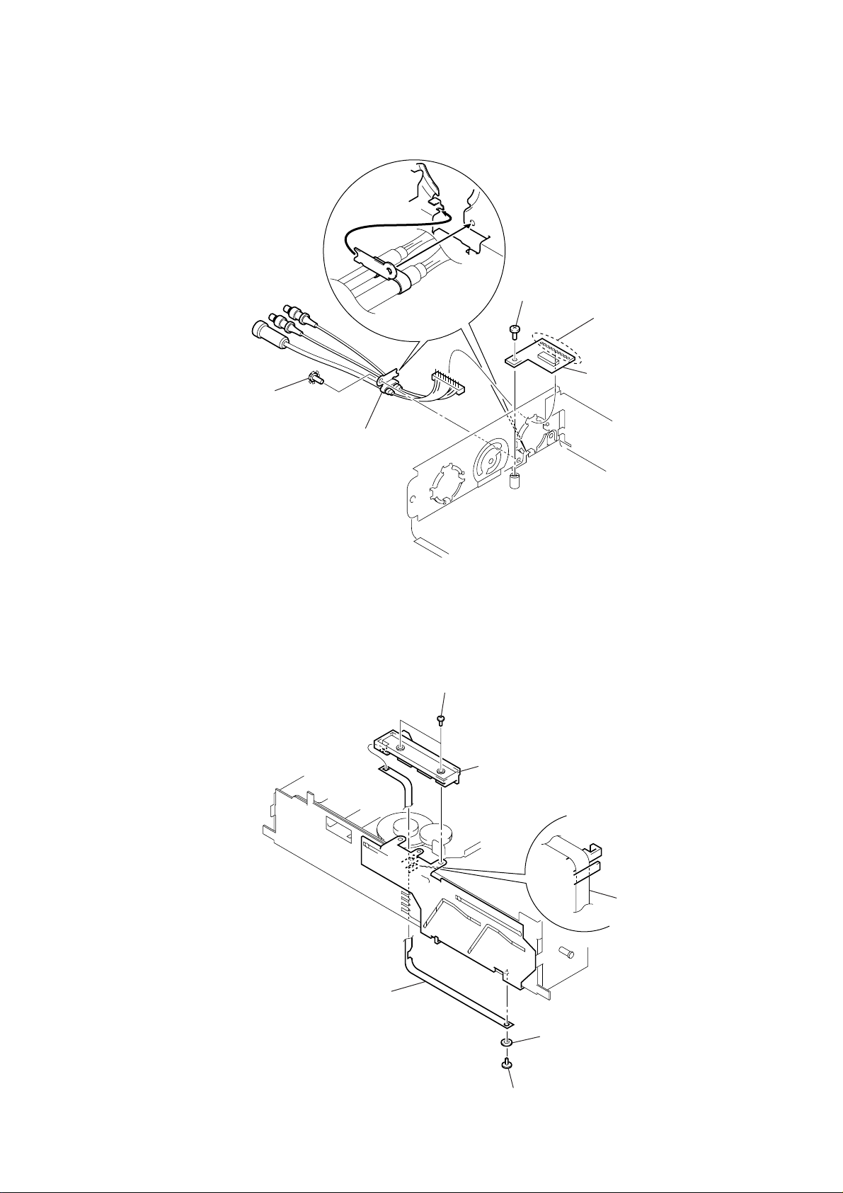
2-4. JACK BOARD
)
4
ground point screw
(PTT2.6 × 6)
5
cord (with connector)
(BUS/RCA)
2
screw (FP)
CDX-T69/T69X
1
Remove ten solders
of the cord (with connector).
3
jack board
2-5. BELT (TS)
5
belt (TS)
3
two screw
(BVTT2
×
4)
4
rack (UD)
belt (TS
2
3.5 washer
1
screw
(M1.7
×
2.2)
7
Page 8
CDX-T69/T69X
)
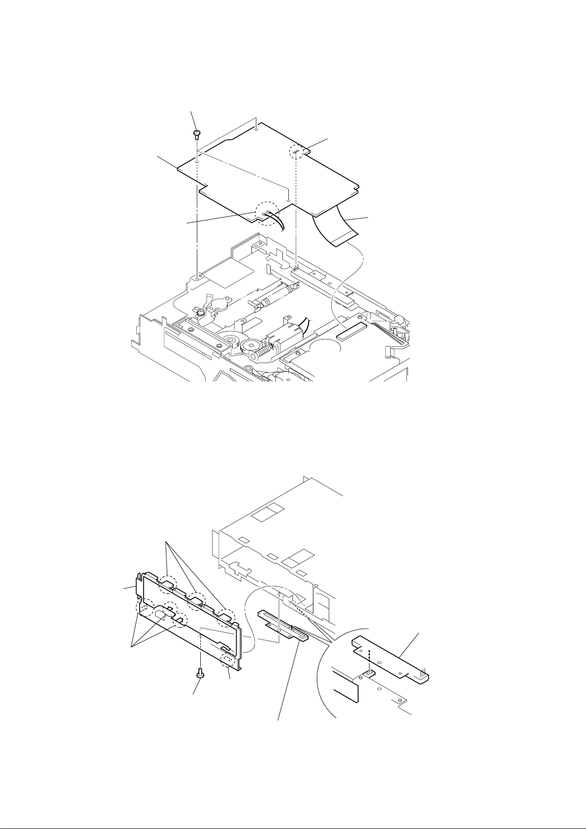
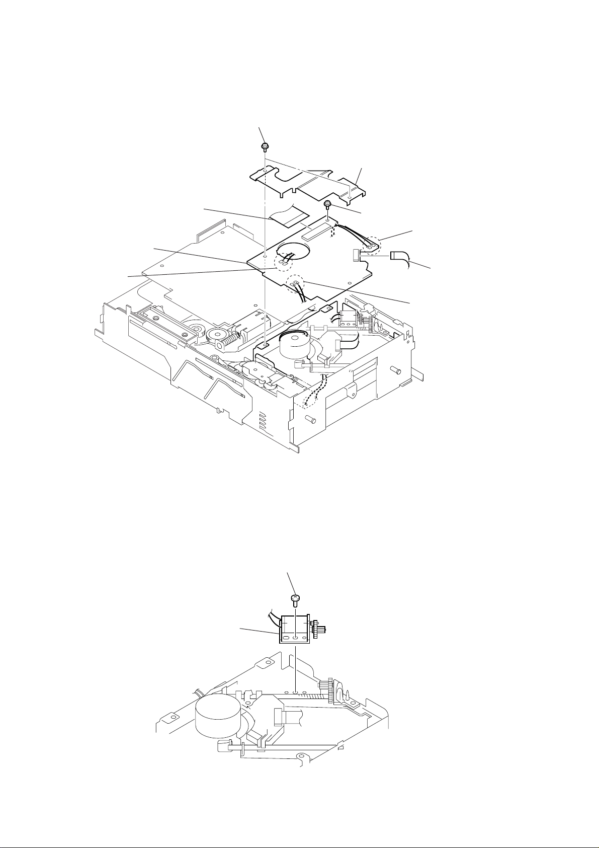
2-6. MAIN BOARD
4
main board
2
Remove two solders
of the elevator motor
lead wires (M104).
3
three screws (FP)
2
Remove three solders
of the slide variable resistor (RV301).
1
main flexible board
(CN101)
2-7. ESCUTCHEON (S), SLIDE VARIABLE RESISTOR (ELEVATOR HEIGHT SENSOR) (RV301)
2
three claws
3
escutcheon (S)
slide variable resistor
(elevator height sensor
(RV301)
2
three claws
2
1
screw (FP)
claw
4
slide variable resistor
(elevator height sensor)
(RV301)
8
Page 9
1
screw
(PTT2
×
3)
2
bracket (MDM)
3
MD motor assy (elevator) (M104)
2-8. MD MOTOR ASSY (ELEVATOR) (M104)
CDX-T69/T69X
2-9. LE MOTOR ASSY (CHUCKING) (M103)
3
screw
(P1.7
×
5
2.2)
2
tension spring (rack)
6
LE motor assy (chucking) (M103)
1
Remove two solders of
the chucking motor lead wires (M103).
7
bracket (LEM)
4
9
Page 10
CDX-T69/T69X
s
2-10. RF BOARD
6
2
Remove two solders of
the spindle motor lead
wires (M102).
1
main flexible board
(CN101)
RF board
3
two screws
(PS2
×
4)
4
heat sink
5
screw
(PS2
×
4)
2
Remove two solders of
the sled motor lead wires
(M101).
1
OP flexible board
(CN102)
2
Remove two solders of
the chucking motor lead wire
(M103).
2-11. SLED MOTOR COMPLETE ASSY (M101)
1
2
sled motor complete assy (M101)
screw
(P2
×
2.2)
10
Page 11
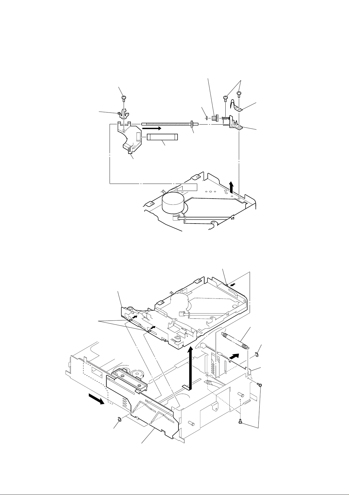
2-12. OPTICAL PICK-UP (KSS-720A)
1
tension spring
5
Open the main chassis assy
in the direction of arrow
B
.
2
Move the slider (6R) fully in the
direction of arrow
A
to move the
chassis (EV) assy down.
6
shaft (EVGR)
7
two shafts (EVGL)
4
two type-E stop rings 2.0
4
type-E stop ring 2.0
A
B
8
chassis (EV) assy
3
three screws
(PTT2
×
3)
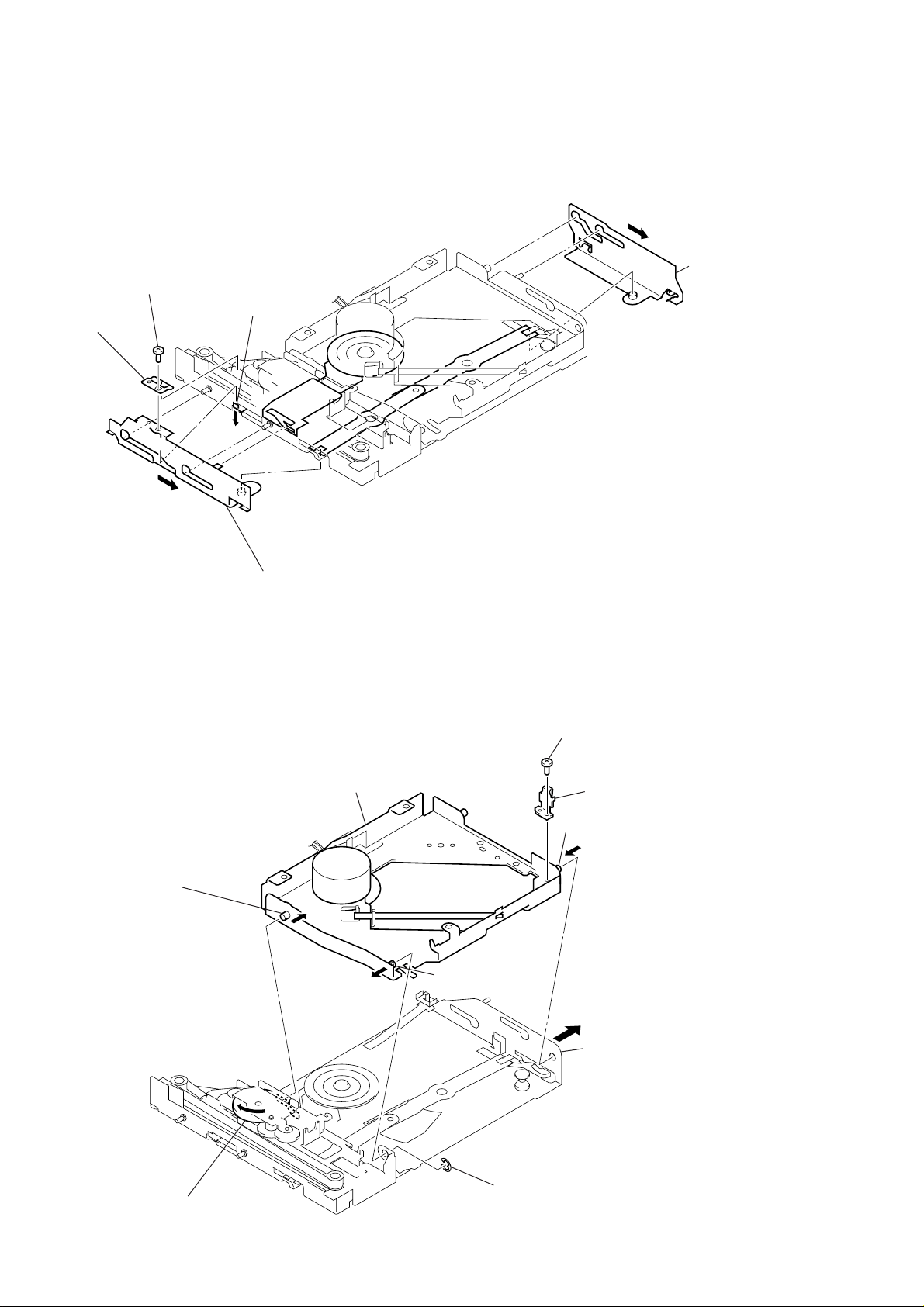
8
screw
(P2 × 3)
9
detent spring (sled)
qa
optical pick-up (KSS-720A)
6
5
washer
(DIA. 1.2)
0
1
OP flexible board
gear (SL2)
shaft (sled feed) assy
A
CDX-T69/T69X
2
two screws
(P2 × 3)
3
spring (sled front point)
7
bearing (sled) assy
4
Lift up the bearing (sled) assy in the
direction of arrow A and remove it from
the shaft (sled feed) assy.
2-13. CHASSIS (EV) ASSY
11
Page 12
CDX-T69/T69X
2-14. LEVER (CHK.L) ASSY, LEVER (CHK.R) ASSY
1
screw
(P1.7 × 2.2)
2
joint (CHK)
leaf spring (D retainer R)
B
3
Move the lever (CHK.L) assy
fully in the direction of arrow A.
A
4
lever (CHK.L) assy
A
3
Move the lever (CHK.R) assy
fully in the direction of arrow A.
5
Remove the lever (CHK.R) assy pushing down
the leaf spring (D retainer R) in the direction of arrow B.
2-15. CHASSIS (OP) BLOCK SERVICE ASSY
8
chassis (OP) block service assy
7
shaft
2
6
screw
(P2
3
shaft
×
1.8)
leaf spring (FOP)
12
A
1
Turn the gear (LE2) assy
fully in the direction of arrow
A
6
shaft
B
5
Open the chassis (EV) assy
in the direction of arrow
4
type-E stop ring 2.0
.
B
.
Page 13

SECTION 3
MECHANICAL ADJUSTMENT
ELEVATOR HEIGHT (ADDRESS) ADJUSTMENT
CDX-T69/T69X
Note: This adjustments is necessary when the system controller (IC301),
variable resistor (R V302), le ver (CHK.L) assy , lev er (CHK.R) assy ,
or chassis (EV) assy was replaced for any repair.
Connection:
power supply
(DC 14.4 V)
master unit
+
GND
BUS cable
compact disc changer
Adjustment Method:
1. Connect this set to the master unit (e.g. MDX-C7970/C7970R),
load a disc magazine, and place the set vertically as shown
below.
2. Connect the regulated power supply to the master unit, and
turn the power on.
3. Press the DISC button on the master unit and select DISC 6.
4. Adjust the variable resistor RV302 so that the ref erence holes
of the slider (6L) and of the chassis (6B) meet within an error
of ±0.15 mm when the tray is loaded at address 6.
RV302
chassis (6B)
slider (6L)
(reference hole)
0.15mm 0.15mm
slider (6L)
slider (6L)
(reference hole)
chassis (6B)
(address 6 hole)
13
Page 14

CDX-T69/T69X
SECTION 4
ELECTRICAL CHECK
Note:
1. This check is performed with the set placed horizontally.
2. Power supply voltage: DC14.4 V (more than 3 A).
3. Be sure to use the disc “YEDS-18” parts code: 3-702-101-01, but only
when indicated.
Connection:
power supply
(DC 14.4 V)
master unit
+
GND
BUS cable
FOCUS BIAS CHECK
Connection:
– RF Board (Component Side) –
oscilloscope
(AC range)
+
–
IC101
TP (VC)TP (RFAC)
compact disc changer
Procedure:
1. Connect the oscilloscope to TP (RFAC) and TP (VC) on the
RF board.
2. Put the set into play mode by loading the disc (YEDS-18).
3. Confirm that oscilloscope waveform is clear and check RF signal level is correct or not.
Note:
Clear RF signal waveform means that the shape “◊” can be clearly distinguished at the center of the waveform.
RF signal waveform
VOLT/DIV: 200 mV
TIME/DIV: 500 ns
(10 : 1 probe in use)
level: 1.4
+ 0.3
– 0.4
Vp-p
14
When observing the eye pattern, set the oscilloscope to AC range
and raise the vertical sensitivity so that it may be easily seen.
Page 15

TRACKING OFFSET CHECK
Connection:
– RF Board (Component Side) –
oscilloscope
(DC range)
+
–
TP (TE)
IC101
CDX-T69/T69X
TP (VC)
Procedure:
1. Connect the oscilloscope to TP (TE) and TP (VC) on the RF
board.
2. Put the set into play mode by loading the disc (YEDS-18).
[ AMS ] button on the master unit, and check
3. Press the
. >
the traverse waveform*.
4. Confirm that the oscilloscope waveform is symmetrical on the
top and bottom in relation to 0 V dc, and check this level.
* Traverse waveform: This is the tracking error wave form appears
when crossing the track.
Traverse waveform
A
0 V
B
VOLT/DIV: 500 mV
TIME/DIV: 2 ms
Center: 0 V
A=B
traverse waveform
(100 track jump waveform)
15
Page 16

CDX-T69/T69X
MEMO
16
Page 17

5-1. BLOCK DIAGRAM – SERVO Section –
CDX-T69/T69X
SECTION 5
DIAGRAMS
FILTER
DETECTOR
A
B
C
D
E
F
LASER DIODE
OPTICAL
PICK-UP BLOCK
(KSS-720A)
2-AXIS DEVICE
(TRACKING)
(FOCUS)
I-V AMP
PD LD
A
6
B
7
C
8
D
9
E
10
F
11
AUTOMATIC
M101
(SLED)
M102
(SPINDLE)
M103
(CHUCKING)
POWER
CONTROL
Q101
M
M
M
RF AMP,
FOCUS/TRACKING ERROR AMP
RFAC
SUMMING
AMP
1
IC101
AC
SUM
4
FOCUS
ERROR
AMP
TRACKING
ERROR
AMP
LD
TRACKING/FOCUS COIL DRIVE,
SLED/SPINDLE/CHUCKING
MOTOR DRIVE
VO4+
6
VO4–
VO3+
VO3–
VO1+
VO1–
VO2+
VO2–
VL0+
VL0–
DRIVE
DRIVE
MOTOR
DRIVE
MOTOR
DRIVE
MOTOR
DRIVE
7
8
9
12
13
10
11
5
4
3
SUMMING
IC201
COIL
COIL
EQ
IN
RFAC
VCA
RFDC
AMP
RW/ROM
RW/ROM
APC AMP
VIN4+
VIN4–
VIN3+
VIN3–
VIN1+B
VIN1–B
VIN2–
FWD
REV
53 56 5554
FILI
PCO
FILO
CLTV
RFAC
RF EQ
AMP
31
32
25
24
19
18
21
1
2
RFDCO
DC OFST
SW
15
RFDC
28
30
FE
16
TE
18
12
PD
2
TEDR
30
TRDR
31
FFDR
32
FRDR
33
SFDR
28
SRDR
29
MDP
26
RFAC
51
ASYI
49
ASYO
48
FE
TE
PWM GENERATOR
DIGITAL
CLV
ASYMMENTRY
CORRECTOR
RF AMP OFFSET
CONTROL SWITCH
Q102
ANALOG SWITCH
A/D CONVERTER
DIGITAL SERVO
SIGNAL PROCESS
ON : When the optical pick-up
is inner position
FE
TE
RFDC
43 39 41 40
FE
TE
RFDC
OP AMP
MIRR
DFCT
SE
FOK
DIGITAL
PLL
EFM
DE-
MODULATOR
SUBCODE
PROCESS
SW101
(LIMIT)
16k RAM
INTERNAL BUS
CORRECTOR
ERROR
CPU
INTERFACE
SERVO AUTO
SEQUENCER
SERVO
INTERFACE
SSTP
27
D/A
INTERFACE
EMPH
GFS
DATA
CLOK
XLAT
SENS
SQSO
SQCK
SCOR
SCLK
FOK
SERIAL
IN
INTERFACE
DIGITAL SIGNAL PROCESSOR,
DIGITAL SERVO PROCESSOR,
DIGITAL FILTER, D/A CONVERTER
CD-ROM/RW
SELECT SWITCH
Q301
64
18
5
7
6
8
1
2
20
9
24
3XRST
DIGITAL FILTER,
NOISE SHAPER
IC401
99
66
42
61
59
60
44
56
58
52
43
41
62
5
6
98
INTEGRATOR
RW SWL
EMPH
GFS
CDDAT
CDCLK
CDLAT
SENS
SQSO
SQCK
SCOR
SCLK
FOK
XRST
LOADF
LOADR
LIM SW
AOUT2
PWM
&
AOUT1
SYSTEM CONTROLLER
IC301 (1/2)
77
70
CLOCK
GENERATOR
MUTE
BUFFER
TIMING
LOGIC
LOUT1
72
LOUT2
75
XTAO
67
XTAI
60
MUTING CONTROL
SWITCH
Q501
GROUND-
ISOLATION
IC501
X401
16.9344MHz
MUTING
Q502, 503
AIN2
76
AIN1
71
67
• SIGNAL PATH
: CD PLAY
CN902 (1/2)
(L)
(R)
ON : When completion of the disc
chucking operation
SW102
(CHUCKING END DETECT)
LOAD SW
97
SAVE SW
96
1717
Page 18

CDX-T69/T69X
5-2. BLOCK DIAGRAM – BUS CONTROL/POWER SUPPLY Section –
SYSTEM CONTROLLER
MAG SW
MAGLK SW
ELVF
ELVR
IC301 (2/2)
MCK
EHS
AVRH
BUCHK
EJECT SW
37
36
34
46
SW303
Z
50
M104
(ELEVATOR)
SW301
MAGAZINE
DETECT
95
SW302
MAGAZINE IN/OUT
DETECT
5151
ELEVATOR
MOTOR DRIVE
IC302
OUT1
9
M
OUT2
7
MOTOR
DRIVE
IN1
IN2
3
4
4
3
RV302
ELEVATOR HEIGHT
(ADDRESS)
RV301
ELEVATOR HEIGHT
SENSOR
BATTERY
CHECK
SERVO +3V
Q203
+3V
REGULATOR
Q202
SERVO +5V
D210
D209
+5V
REGULATOR
IC203
DRIVER +8V
+8V
REGULATOR
IC202
X180X0
81
X301
4MHz
ELVON
RESET
UNI SI
UNI SO
UNI CK
BUSON
24
75
16
17
18
45
RESET SIGNAL
GENERATOR
IC204
BUS INTERFACE
(FOR SONY BUS)
IC201
SO
10 6
SI
9
SCK
11 4
BUSON OUT
1 12
BUSON OUT
13 2
RESET
8 7
RESET
SWITCH
µCOM B+
VCC
DATA
CLK
LOF
BUSON IN
RST
CN902 (2/2)
REGULATOR
Q205, 206
14
PS902
8
B. UP
6
DATA
5
CLK
4
BUSON
7
RST
1818
Page 19

CDX-T69/T69X
5-3. NOTE FOR PRINTED WIRING BOARDS AND SCHEMATIC DIAGRAMS
Note on Printed Wiring Board:
• X : parts extracted from the component side.
• Y : parts extracted from the conductor side.
f
•
: internal component.
• : Pattern from the side which enables seeing.
(The other layers' patterns are not indicated.)
Caution:
Pattern face side: Parts on the pattern face side seen from
(Conductor Side) the pattern face are indicated.
Parts face side: Parts on the par ts face side seen from
(Component Side) the parts face are indicated.
Note on Schematic Diagram:
• All capacitors are in µF unless otherwise noted. pF: µµF
50 WV or less are not indicated except for electrolytics
and tantalums.
• All resistors are in Ω and 1/
specified.
f
•
: internal component.
4
• C : panel designation.
Note:
The components identified by mark 0 or dotted
line with mark 0 are critical for safety.
Replace only with part
number specified.
Note:
Les composants identifiés par
une marque 0 sont critiques
pour la sécurité.
Ne les remplacer que par une
pièce portant le numéro
spécifié.
• A : B+ Line.
• H : adjustment for repair.
• Power v oltage is dc 14.4V and fed with regulated dc power
supply from CD changer controller.
• Voltages and waveforms are dc with respect to ground
under no-signal conditions.
no mark : CD PLAY
• Voltages are tak en with a V OM (Input impedance 10 MΩ).
Voltage variations may be noted due to normal production tolerances.
• Waveforms are taken with a oscilloscope.
Voltage variations may be noted due to normal production tolerances.
• Circled numbers refer to waveforms.
• Signal path.
J : CD PLAY
W or less unless otherwise
• Waveforms – RF Board –
1 IC101 qg (RFAC) (CD play mode)
1.4
2 IC101 qh (FE) (CD play mode)
3 IC101 qk (TE) (CD play mode)
+ 0.3
Vp-p
– 0.4
Approx
180 mVp-p
– MAIN Board –
1 IC301 ia (X1) (CD play mode)
250 ns
2 IC401 wh (MDP) (CD play mode)
µ
s
7.5
3 IC401 yj (XTAO) (CD play mode)
3.8 Vp-p
1.8 Vp-p
Approx
900 mVp-p
4.2 Vp-p
59.1 ns
1919
Page 20

CDX-T69/T69X
5-4. PRINTED WIRING BOARDS – RF Board –
1
A
B
MAIN
BOARD
A
C
CN202
(Page 22)
FLEXIBLE
D
E
F
G
H
2 3 4 5 6 7 8 9 10 11 12 13 14
MAIN
BOARD
RF BOARD
(COMPONENT SIDE)
(CHASSIS)
CN101
(SPINDLE)
RED
M102
(RFAC)
M
RF BOARD
BLK
M101
M
OP FLEXIBLE
BOARD
R215
(SLED)
OPTICAL
PICK-UP
BLOCK
KSS-720A
1-680-829-
C117
C109
C115
C108
C107
C202
12
(12)
RED
R106
R128
C116
C111
R119
Q102
C113
R220
R210
R208
R206
R204
C114
TP
(TE)
R109
TP
TP
(VC)
BLK
R117
R118
R223
R222
R116
R214
C119
R212
R209
R207
R205
R203
R202
RED
R120
R218
R213
R211
C217
R121
IC101
C112
R113
R112
R110
C211
R219
C208
C206
C205
C204
C203
R201
C220
BLK
16
CN102
R111
R103
IC201
1
Q101
R127
R216
C209
M
M103
(CHUCKING)
(CONDUCTOR SIDE)
C201
SW102
SW102
(CHUCKING END DETECT)
SW101
(LIMIT)
C110
1-680-829-
12
(12)
• Semiconductor
Location
Ref. No. Location
IC101 C-5
IC201 F-6
Q101 D-6
Q102 E-5
2020
Page 21

5-5. SCHEMATIC DIAGRAM – RF Board –• See page 19 for Waveforms. • See page 27 for IC Block Diagrams.
CDX-T69/T69X
2-AXIS
DEVICE
DETECTOR
(FOCUS) (TRACKING)
LASER DIODE
PD
LD
I-V AMP
Q101
2SA1037AK-T146-R
AUTOMATIC
POWER CONTROL
CN102
16
VCC
VC
OP
FLEXIBLE
BOARD
1
M103
(CHUCKING)
M102
(SPINDLE)
M101
(SLED)
F(-)
T(-)
T(+)
F(+)
E
F
VCC
VC
VR
PD
LD
GND
A
C
B
D
16P
C117
0.1
C108
100
4V
C220
0.1
TP1
TP2
TP3
TP4
TP6
TP5
R127
22
C107
100
R103
4V
22
C112
0.1
R121
22k
R120
22k
C115
C114
100
4V 0.1
C109
0.1
C119
0.1
RF AMP,
FOCUS/TRACKING
ERROR AMP
LD
PD
EQ_
IN
AC_SUM
GND
A
B
C
D
E
F
SW
TE_BAL
DVCC
DVC
RFAC FE
IC101
CXA2581N-T4
FOCUS/TRACKING COIL DRIVE
SPINDLE/SLED/CHUCKING
MOTOR DRIVE
IC201
LA6576L-TE
FWD
REV
VCC2
VL0-
VL0+
VO4+
VREF-IN
VO4-
VIN1-SW
VO3+
VREF-OUT
VO3-
REG-OUT
VO2+
VO2-
VO1+
VO1-
VCC1
VIN1
VIN1-A
VIN1+A
VIN1-B VIN1+B
RFDCI
RFDCO
REG-IN
OFST
S-GND
MUTE2
MUTE1
VIN4-
VIN4+
VIN3+
VIN3-
VIN2+
VIN2-
DC_
VC
RFC
VFC
BST
RFG
VCC
CEI
CE
TE
FEI
VIN4
VIN3
VIN2
R117
3.3k
C113
R106
C202
0.1
R114
10k 10k
100k
C201
R109
100k
C111 R119
0.1 1k
0.1
R110 R112
470
16V
C110
100
6.3V
R118 C116
22k 0.1
18k
R201
10k
C208 R213 R214
0.022 47k 56k
C211
0.022
C209 R215
0.022 10k
R116
100k
R115
15k
R113
12k
R111
10k
R202 C217
10k 0.1
C203 R203 R204
470p 10k 33k
C205 R207 R208
470p 10k 33k
C206
470p
R218 R219
10k 33k
CONTROL SWITCH
R209
10k
R211
47k
R128
1k
Q102
DTC124EKA
-T146
RF AMP OFFSET
R206R205C204
33k10k470p
R210
33k
R212
68k
R216
33k
SW101
(LIMIT)
ON:WHEN THE OPTICAL PICK-UP IS
INNER POSITION
SW102
(CHUCKING END DETECT)
ON:WHEN COMPLETION OF THE DISC
CHUCKING OPERATION
(RFAC)
TP
TP
(VC)
TP
(TE)
AA1
AA2
AA3
AA4
AA5
AA6
AA7
AA3
AA4
R222 R223
1k 820
AA2
AA1
R220
12k
AA5
AA7
AA6
SW101
SW102
CN101
22P
R/RW_SEL
LIM_SW
SAVE_SW
RFAC
RFDC
VC
TE
FE
DVCC(3V)
GND(5V)
5V
FRDR
FFDR
TRDR
TFDR
MDP
SRDR
SFDR
LOADR
LOADF
GND(8V)
8V
MAIN
FLEXIBLE
BOARD
(Page 25)
The components identified by mark 0 or dotted
line with mark 0 are critical for safety.
Replace only with part number specified.
Les composants identifiés par une marque 0 sont
critiques pour la sécurité. Ne les remplacer que
par une pièce portant le numéro spécifié.
2121
Page 22

CDX-T69/T69X
• Semiconductor
Location
Ref. No. Location
D201 G-7
D202 G-7
D203 B-5
D204 G-6
D207 F-7
D209 F-6
D210 F-6
D212 G-9
D213 G-7
IC201 G-6
IC203 B-10
IC204 E-6
IC301 D-7
IC302 E-4
IC401 C-4
IC501 G-4
Q202 B-5
Q203 F-5
Q205 E-9
Q206 F-7
Q301 E-3
Q501 F-5
Q502 H-6
Q503 H-6
5-6. PRINTED WIRING BOARDS – MAIN Board (Component Side) –
1
2 3 4 5 6 7 8 9 10
A
(COMPONENT SIDE)
R412
C414
C413
C416
R407
R408
R405
C411
C412
C410
R404
C408
R402
C403
R406
R403
R401
C407
Q301
R309
41
60
C415
C402
40
61
C504
C307
IC401
R506
C502
R505
R504
C304
IC302
B
C
D
E
MAIN BOARD
R410
CN202
MAIN
FLEXIBLE
F
BOARD
C501
R503
C308
21
100
R501
R502
C503
C203
20
C401
1
R306
Q202
R414
D203
C213
R206
R202
C212
R302
C302
D210
R303
R301
IC204
R205
D209
R203
51
75
C211
50
76
R307
IC301
C301
R308
C208
C305
R211
R305
26
100
R209
25
1
R204
D207
C306
C214
Q205
2
IC203
13
C215
G
H
A
RF BOARD
CN101
(Page 20)
R512
R520
R514
R513
R511
C505
C506
R518
R517
IC501
C516
R519
R521
Q203
D201
D202
Q206
C217
D213
SW302
SW302
MAGAZINE
IN/OUT
DETECT
D212
113
CN201
B
1-680-827-
JACK FLEXIBLE
BOARD
JACK BOARD
CN901
(Page 26)
13
(13)
R207
C201
Q502
Q503
C202
R201
D204
Q501
R515
C216
C514
R508
C513
R507
IC201
R510
R509
2222
Page 23

5-7. PRINTED WIRING BOARD – MAIN Board (Conductor Side) –
2 3 4 5 6 7 8 9 10
MAIN BOARD
(CONDUCTOR SIDE)
SW303
Z
A
1
(CHASSIS)
B
C205
C206
C207
C
C204
D
IC202
E
SW301
F
G
H
(CHASSIS)
MAGAZINE
DETECT
CDX-T69/T69X
• Semiconductor
Location
Ref. No. Location
IC202 D-2
C303
RV301
EVEVATOR HEIGHT
SENSOR
RV302
X301
C209
C404
C210
C511
C512
C405
C508
1-680-827-
X401
RED
BLK
13
(13)
C510
C509
C515
(CHASSIS)
M
M104
(EVEVATOR)
2323
Page 24

CDX-T69/T69X
5-8. SCHEMATIC DIAGRAM – MAIN Board (1/2) –• See page 19 for Waveform. • See page 27 for IC Block Diagrams.
(Page 26)
FLEXIBLE
JACK
BOARD
(ELEVATOR)
CN201
LCH
AGND
RCH
BUSON
CLK
DATA
RST
B.UP
B.UP
B.UP
GND
GND
GND
M104
13P
0.1
C217
UDZSTE-1718B
D201
D213
RB521S-30-TE61
Q205
2SB1184TLR
Q205,206
REGULATOR
D207
MA8056-H
100 16V
C206
I
+5V REGULATOR
G
O
100 6.3V
C207
Q202
2SC2712-Y
+3V REGULATOR
NJM78M05DL
220
C215
0.01
D203 R202
MA8039-H-TX
C203
0.1
BP12
BP11
RB521S-30-TE61
D204
C201
0.001
2SC2712-YG
R209R204
47k47k
C208 R211
0.1 100k
IC203
UDZSTE-1718B
D202
Q206
BUSON
R201
47k
RB521S-30-TE61
D212
C202
4700p
C209 C210
100
6.3V
C307
0.01
C308
0.01
C216
0.01
1000
16V 0.01
C204
1000
C214
0.01
C205
C211
16V
100
16V
IC302
BA8272AFV-E2
BUS INTERFACE
(FOR SONY BUS)
RESET SIGNAL
GENERATOR
IC204
XC61CN2502PR
IGO
IC202
NJM2395AF08
C
G
+8V REGULATOR
LB1930M-TL
OUT
BUSON
IN
GND
CLK
VREF
DATA
RST
REG
IC201
O
VCCBUSON
BUSON
OUT
LOF
SCK
SO
SI
RESET
R205
47k
C212
0.01
I
C304
0.01
SCK
SI
SO
LOADF
LOADR
SI
SO
SCK
Q301
DTC124EKA
CD-ROM/RW
SELECT
SWITCH
RAMA5
RAMA6
ELVR
ELVF
LOADF
LOADR
RAMA7
RAMA12
VSS
RAMA14
RAMWE
RAMA13
RAMA8
RAMA9
RAMA11
UNI SI
UNI SO
UNI CK
LEDDAT
LEDCLK
VCC
LEDLAT
CDON
ELVON
RX
RAMA4
SW301
MAGAZINE
W
D S
A
LO
OT
O
B
FL
SAVE_SW
W
E S
V
SA
C
N
DETECT
10
301
BP
SW
G SW
A
M
C
N
6
P8
BP9
T
ES
T
AT
D
EE
B
EL
S
P
ES
C
C
V
A
BP
BP7
EL
EL
CFS
XTS
TE
SYSTEM CONTROLLER
H
S
S
R
V
V
A
A
BP5
LE
EL
G
0 S
SIN
6/1
IC301
MB90473PFV-G
-113-BNDE1
K
S
C
M
EH
2
3
A
A
M
M
A
RA
R
1
0
EY
EY
K
K
X301
4MHz
C301
0.01
0
1
1
0
A
A
IO
M
M
M
A
A
A
R
R
R
S
K
FS
S
V
G
FO
0
1
CC
X
IO
V
M
A
R
N
S
SO
U
EN
CLK
B
S
S
RAMIO2
1A
0A
SS
X
X
X
V
RESET
RAMIO3
RAMIO4
RAMIO5
RAMIO6
RAMIO7
RAMCS
RAMA10
MUTE
EMPH
XWRE
XRDE
XQOK
XRST
CDDAT
CDLAT
CDCLK
SQCK
NC
SQSO
HS
NC
GRSCOR
SCOR
MAGLK SW
K
2
1
0
CH
D
D
D
U
EJECT SW
M
M
M
B
EMPH
XRST
DATA
XLAT
CLOK
SQCK
SQSO
SCOR
R301
1k
C302
0.01
SW302
MAGAZINE
IN/OUT DETECT
LIM_SW
W
EL
S
S
W
LIM
R
K
CL
C
N
EE
TX
R309
1k
R302
100k
1
2
3
4
(Page 25)
5
ELEVATOR
MOTOR DRIVE
D210
UDZS-TE17
R203
150k
D209
1SS355TE
-6.2B
-17
C213
0.33
2SC2712-YG
BATTERY
R206
120k
CHECK
R207
100k
SENS
SCLK
GFS
C305
1
R305 R308
100k 10k 100k
Q203
RV301
ELEVATOR HEIGHT
SENSOR
FOK
10k
R307
RV302RV301
47k10k
BUSON
6
R303
C303
10
16V
SW303
7
8
9
10
11
12
2424
Page 25

5-9. SCHEMATIC DIAGRAM – MAIN Board (2/2) –• See page 19 for Waveforms. • See page 27 for IC Block Diagram.
1
2
C503 C504
R306
10
0.001 0.001
R503
10k
C501
150p
CDX-T69/T69X
C402
0.01
R504
10k
C502
R505 R506R502R501
150p
10k 10k10k10k
EMPH
(Page 24)
C405
220
16V
C404
220
16V
R520
12k
C512
3
Q503
UN2226
4
5
6
7
8
MUTING
Q502
UN2226
MUTING
Q501
DTA115EKA-T146
MUTING CONTROL
SWITCH
C508
47
4V
C513 C505
R509
100p 100p
100k
GROUND-ISOLATION
TLV2362IPW
100p
C514
R510
100k
R508 C511
470 10
R515
10k
C516
0.01
IC501
C515
47
4V
R521
10k
16V
R518 R513
12k 6.8k
C506
100p
R519R507
6.8k4701016V
R511
12k
R512
6.8k
C
C
V
D
N
G
R517
6.8k
R514
12k
C509
C510
47
47
4V
4V
SQSO
C401
SQCK
0.1
XRST
DATA
XLAT
CLOK
SENS
SCLK
GFS
SCOR
TP401
TP402
TP403
TP404
1k
R414
SQSO
SQCK
XRST
SYSM
DATA
XLAT
CLOK
SENS
SCLK
VDD
ATSK
SPOA
SPOB
XLON
WFCK
XUGF
XPCK
GFS
C2PO
SCOR
LMUT
T
2
2
2
2
U
T
D
T2
S1
OU
AIN
A
K
C
K
LO
FO
TP408
MDP
FOK
S
U
VS
VS
A
A
LO
DIGITAL SIGNAL PROCESSOR,
DIGITAL SERVO PROCESSOR,
DIGITAL FILTER,D/A CONVERTER
P
R
P
D
FD
ST
S
S
M
SFDR
LIM_SW
M
D
V
R
A
T
IRR
FC
COUT
D
M
TP407
TP406
TP405
SRDR
T1
U
LO
CXD3017Q
R
D
SR
TFDR
IC401
1
1
T1
D
U
D
IN
V
O
A
A
A
R
R
R
D
FFD
TFD
TR
FFDR
TRDR
z
H
X401
16.9344M
D
D
K
I
SS
AO
TA
X
XT
XV
R
T
D
TES
VSS
FR
FRDR
LRCK
PH
M
D
C
B
PC
EM
XV
1
TES
DOUT
VDD
VSS
AVDD3
PCO
FILI
FILO
CLTV
AVSS3
RFAC
BIAS
ASYI
ASYO
AVDD0
IGEN
AVSS0
ADIO
RFDC
CE
L
XTS
C415
220p
TE
C
SE
FE
V
R412
33k
3.3k
R401
R405
10k
33k
R407
C416
0.01
C413
220p
C414
0.1
C407R402
0.0473.3k
R406
100k
C412C411
0.470.01
R408
33k
R410
100k
R403
2200p
C408
1500p
10k
R404
1M
C410
220p
C403
LIM_SW
SAVE_SW
FRDR
FFDR
TRDR
TFDR
MDP
SRDR
SFDR
LOADR
LOADF
CN202
22P
C306
0.1
(CHASSIS)
R/RW_SEL
LIM_SW
SAVE_SW
RFAC
RFDC
VC
TE
FE
DVCC(3V)
GND(5V)
5V
FRDR
FFDR
TRDR
TFDR
MDP
SRDR
SFDR
LOADR
LOADF
GND(8V)
8V
MAIN
FLEXIBLE
BOARD
(Page 21)
9
10
11
12
2525
Page 26

CDX-T69/T69X
5-10. PRINTED WIRING BOARDS – JACK Board – 5-11. SCHEMATIC DIAGRAM – JACK Board –
LCH
AGND
RCH
BUSON
CLK
DATA
RST
B.UP
GND
GND
JACK BOARD
(COMPONENT SIDE)
(L)
(R)
(FOR SONY BUS)
CN902 CN901
10P 13P
PS902
FB901
FB902
FB903
5A
24V
(CHASSIS)
LCH
AGND
RCH
BUSON
CLK
DATA
RST
B.UP
B.UP
B.UP
GND
GND
GND
JACK
FLEXIBLE
BOARD
(Page 24)
JACK BOARD
(CONDUCTOR SIDE)
(FOR SONY BUS)
5
6
7
8
2 13
PS902
CN902
4
CN901
1-680-828-
(R) (L)
FB903
FB901
FB902
13
13
(13)
110
13
1-680-828-
(13)
JACK FLEXIBLE
B
(CHASSIS)
BOARD
MAIN BOARD
CN201
(Page 22)
2626
Page 27

• IC Block Diagrams – RF Board –
IC101 CXA2581N-T4
DVC
VC
–
+
VOFST
CDX-T69/T69X
RW/ROM
30
DC OFST
29
A
B
C
D
DVC
–
+
RW/ROM
–
+
DVC
VCC
RFDCI
28
RFDCO
VC
27
VC
EQ IN
AC SUM
GND
SW
DVCC
DVC
RFAC
APC AMP
DVC
VC
A
A
B
C
D
APC-OFF
(Hi-Z)
RW/ROM
(H/L)
RFAC
SUMMING
AMP
BCD
GM
GM
EQ
EQ ON/OFF
RW/ROM
B
C
A
D
B
D
A
C
VOFST
–
+
RW/ROM
RW/ROM
–
+
RW/ROM
RW/ROM
VOFST
–
+
RW/ROM
RFAC
VCA
VCC
–
+
DVC
VC
VC
–
+
DVC
VC
1
LD
2
PD
3
4
5
6
A
7
B
8
C
9
D
10
E
11
F
12
13
14
15
26
RFC
25
VFC
24
BST
23
RFG
22
VCC
CEI
21
20
CE
19
TE BAL
18
TE
17
FEI
16
FE
27
Page 28

CDX-T69/T69X
IC201 LA6576L-TE-L
FWD
1
INPUT
2
REV
3
VCC2
4
VLO–
5
VLO+
6
VO4+
7
VO4–
8
VO3+
9
VO3–
10
VO2+
VO2–
11
12
VO1+
VO1–
13
VCC1
14
15
VIN1
OUTPUT
CONTROL
LEVEL
SHIFT
LEVEL
SHIFT
–
+
LEVEL
SHIFT
LEVEL
SHIFT
–
+
THERMAL SHUT DOWN
–
+
5VREG
+
–
–
+
–
+
CH2-4
MUTE
CH1
MUTE
VIN1/VREF
SWITCH
–
+
–
+
+
–
+
–
S-GND
36
35
MUTE2
34
MUTE1
33
VIN4
32
VIN4–
31
VIN4+
30
VREF-IN
29
VIN1 (VREF)-SW
28
VREF-OUT (CH1)
27
REG-OUT
REG-IN
26
25
VIN3+
VIN3–
24
VIN3
23
22
VIN2+
21
VIN2–
VIN2
20
VIN1+B
19
VIN1–A
VIN1+A
VIN1–B
16
–
AMP-A
+
17
–
18
AMP-B
+
28
Page 29

– MAIN Board –
IC201 BA8272AFV-E2 IC302 LB1930M-TLM
VCC
1
BUFFER
NC
VCC
BUS ON
14 13 12
LINK OFF
11
CLK OUT
DATA OUT
10
DATA IN
RESET
89
RESET
SWITCH
IN1
IN2
S-GND
2
3
4
BUFFER
5
CONTROL
CIRCUIT
MOTOR
DRIVE
CIRCUIT
CDX-T69/T69X
NC
10
OUT1
9
8
NC
7
OUT2
P-GND
6
2 3
1
BUS ON OUT
BUS ON IN
5 6 7
4
GND
BUS CLK
IC401 CXD3017Q
DOUT
60
DIGITAL
OUT
LRCK
PCMD
BCK
EMPH
XVDD
XTAI
XTAO
XVSS
AVDD1
AOUT1
AIN1
LOUT1
AVSS1
AVSS2
LOUT2
AIN2
AOUT2
AVDD2
RMUT
LMUT
61
62
63
64
65
66
67
68
69
70
71
72
73
74
75
76
77
78
79
80
D/A
INTERFACE
TIMING
LOGIC
OVER SAMPLING
NOISE SHAPER
DIGITAL FILTER
VREF
BUS DATA
PWM
3rd ORDER
SERIAL IN
INTERFACE
VDD
59
58
INTERNAL BUS
PWM
VSS
57
BUS RESET
AVDD3
CORRECTOR
ERROR
16K
RAM
SUBCODE
PROCESSOR
FILO
FILI
PCO
54
56
55
53
DIGITAL
PLL
EFM
DEMODULATOR
SERVO
INTERFACE
SERVO AUTO
SEQUENCER
CLTV
AVSS3
52
ASYI
BIAS
RFAC
51
49
50
ASYMMETRY
CORRECTOR
48
ASYO
AVDD0
47
46
IGEN
AVSS0
45
ADIO
44
SERVO DSP
FOCUS
SERVO
TRACKING
SERVO
SLED
SERVO
CE
TE
RFDC
43
41
42
OPERATIONAL
AMPLIFIER
ANALOG SWITCH
A/D
CONVERTER
PWM GENERATOR
CLOCK
GENERATOR
FOCUS PWM
GENERATOR
TRACKING
PWM GENERATOR
SLED PWM
GENERATOR
DIGITAL
CLV
MIRR, DFCT,
FOK
DETECTOR
SE
40
FE
39
VC
38
XTSL
37
TES1
36
TEST
35
VSS
34
33
FRDR
32
FFDR
TRDR
31
TFDR
30
SRDR
29
28
SFDR
SSTP
27
MDP
26
25
LOCK
FOK
24
DFCT
23
22
MIRR
1
2
SQSO
SQCK
3
XRST
4
SYSM
CPU
INTERFACE
7
5
6
XLAT
DATA
CLOK
8
SENS
9
10
SCLK
11 12
VDD
ATSK
13
SPOA
SPOB
14
1516171819
XLON
WFCK
XUGF
XPCK
GFS
20
C2PO
SCOR
COUT
21
29
Page 30

CDX-T69/T69X
5-12. IC PIN FUNCTION DESCRIPTION
• MAIN BOARD IC301 MB90473PFV-G-113-BNDE1 (SYSTEM CONTROLLER)
Pin No. Pin Name I/O Description
1, 2
RAMA5, RAMA6
3 ELVR O
O Address signal output to the S-RAM Not used
Motor drive signal (elevator down direction) output to the elevator motor drive
“L” active
4 ELVF O
5 LOADF O
6 LOADR O
RAMA7, RAMA12
7, 8
9 VSS — Ground terminal
10 RAMA14 O Address signal output to the S-RAM Not used
11 RAMWE O Write enable output to the S-RAM Not used
12 to15
30, 31 NC O Not used
RAMA13, RAMA8,
RAMA9, RAMA11
16 UNI SI I Serial data input from the SONY bus interface
17 UNI SO O Serial data output to the SONY bus interface
18 UNI CK I Serial data transfer clock signal input from the SONY bus interface
19 LEDDAT O Not used
20 LEDCLK O Not used
21 VCC — Power supply terminal
22 LEDLAT O Not used
23 CDON O Power supply on/off control signal output terminal “H”: power on Not used
24 ELVON O Mechanism deck section power supply on/off control signal output “H”: power on
25 RX I Input terminal at the flash memory data write mode Not used
26 TX O Output terminal at the flash memory data write mode Not used
27 NC O Not used
28 EECLK O Serial data transfer clock signal output to the EEPROM Not used
29 FL BOOT I Flash memory data write control signal input terminal “L” active Not used (fixed at “H”)
32 EEDAT I/O Two-way data bus with the EEPROM Not used (pull down)
33 AVCC — Power supply terminal (for A/D converter)
34 AVRH I Reference voltage input terminal (for A/D converter)
35 AVSS — Ground terminal (for A/D converter)
36 EHS I
Motor drive signal (elevator up direction) output to the elevator motor drive
“L” active
Motor drive signal (load chucking direction) output to the chucking motor drive
“L” active
Motor drive signal (save direction) output to the chucking motor drive
“L” active
O Address signal output to the S-RAM Not used
O Address signal output to the S-RAM Not used
Elevator height position detection signal input from the elevator height sensor
(A/D input)
37 MCK I
38, 39 KEY0, KEY1 I Not used (fixed at “H”)
40 VSS — Ground terminal
41 FOK I Focus OK signal input from the DSP “L”: NG, “H”: OK
42 GFS I Guard frame sync signal input from the DSP “L”: NG, “H”: OK
43 SCLK O Serial data reading clock signal output to the DSP
44 SENS I Internal status signal (sense signal) input from the DSP
45 BUSON I Bus on/off control signal input from the SONY bus interface “H”: bus on
46 BUCHK I
Input of detection signal for the fine adjustment (elevator height (address) adjustment) of elevator
height position (A/D input)
Battery detection signal input “L”: battery on
30
Page 31

Pin No. Pin Name I/O Description
47, 48 MD0, MD1 I Setting terminal for the CPU operational mode (fixed at “H” in this set)
49 MD2 I Setting terminal for the CPU operational mode (fixed at “L” in this set)
50 EJECT SW I Eject switch input terminal “L” active
51 MAGLK SW I
52 SCOR I Subcode sync (S0+S1) detection signal input from the DSP
53 GRSCOR I Subcode sync (S0+S1) detection signal input terminal Not used
54 NC O Not used
55 HS O
56 SQSO I Subcode Q data input from the DSP
57 NC O Not used
58 SQCK O Subcode Q data reading clock signal output to the DSP
59 CDCLK O Serial data transfer clock signal output to the DSP
60 CDLAT O Serial data latch pulse signal output to the DSP
61 CDDAT O Serial data output to the DSP
62 XRST O System reset signal output to the DSP “L”: reset
63 XQOK O Subcode Q OK pulse signal output terminal Not used
64 XRDE O D-RAM read enable signal output terminal Not used
65 XWRE O D-RAM write enable signal output terminal Not used
66 EMPH O Emphasis control signal output to the DSP “H”: emphasis on
67 MUTE O Audio line muting on/off control signal output “H”: muting on
68 RAMA10 O Address signal output to the S-RAM Not used
69 RAMCS O Chip select enable output to the S-RAM Not used
70 to 74
RAMIO7 to
RAMIO3
Magazine in/out detect switch input terminal
“L”: magazine in/out operation, “H”: normally
Normal/high speed playback control signal output terminal
“L”: high speed playback Not used
I/O Two-way data bus with the S-RAM Not used
CDX-T69/T69X
75 RESET I
76 RAMIO2 I/O Two-way data bus with the S-RAM Not used
77 X1A O Sub system clock output terminal Not used
78 X0A I Sub system clock input terminal Not used (fixed at “L”)
79 VSS — Ground terminal
80 X0 I Main system clock input terminal (4 MHz)
81 X1 O Main system clock output terminal (4 MHz)
82 VCC — Power supply terminal
83, 84
85 to 88
RAMIO1, RAMIO0
RAMA0 to RAMA3
89 SINGLE I
90 6/10 SEL I
91 CFSEL I Custom file on/off setting terminal “L”: custom file on Not used (fixed at “H”)
92 TEXTSEL I
93 ESPSEL I ESP mode setting terminal “L”: ESP on Not used (fixed at “H”)
94 TEST I Test on/off setting terminal “L”: test mode Not used (fixed at “H”)
95 MAG SW I Magazine detect switch input terminal “L”: magazine is set
System reset signal input from the SONY bus interface and reset signal generator “L”: reset
For several hundreds msec. after the power supply rises, “L” is input, then it changes to “H”
I/O Two-way data bus with the S-RAM Not used
O Address signal output to the S-RAM Not used
Setting terminal for the single disc/multiple discs mode
“L”: single disc mode, “H”: multiple discs mode (fixed at “H”)
Setting terminal for the 6 discs changer/10 discs changer model
“L”: 10 discs changer model, “H”: 6 discs changer model (fixed at “H”)
CD text mode setting terminal
“L”: CD text on, “H”: does not display track name Not used (fixed at “H”)
31
Page 32

CDX-T69/T69X
Pin No. Pin Name I/O Description
96 SAVE SW I
Chucking end detect switch input terminal
“L”: When completion of the disc chucking, loading or save operation
97 LOAD SW I
98 LIM SW I
99 RW SEL O CD-ROM/RW selection signal output “L”: CD-RW, “H”: CD-ROM
100 RAMA4 O Address signal output to the S-RAM Not used
Chucking end detect switch input terminal
“L”: When completion of the disc chucking, loading or save operation
Sled limit in detect switch input terminal
“L”: When the optical pick-up is inner position
32
Page 33

SECTION 6
EXPLODED VIEWS
CDX-T69/T69X
NOTE:
• -XX and -X mean standardized parts, so they
may have some difference from the original
one.
• Color Indication of Appearance Parts
Example:
KNOB, BALANCE (WHITE) . . . (RED)
↑↑
Parts Color Cabinet's Color
6-1. CASE SECTION
3
2
• Items marked “*” are not stocked since they
are seldom required for routine service. Some
delay should be anticipated when ordering
these items.
• The mechanical parts with no reference number in the exploded views are not supplied.
• Accessories are given in the last of the electrical parts list.
4
#1
#1
1
17
13
18
19
The components identified by mark
0 or dotted line with mark 0 are
critical for safety.
Replace only with part number
specified.
Les composants identifiés par une
marque 0 sont critiquens pour la
sécurité.
Ne les remplacer que par une pièce
portant le numéro spécifié.
5
#1
4
#1
10
MG-276A-159
16
not supplied
20
8
15
RV301
not supplied
14
13
12
13
Ref. No. Part No. Description Remark
1 3-225-801-11 DOOR (S) (CDX-T69)
1 3-225-801-21 DOOR (S) (CDX-T69X)
2 3-225-802-01 BUCKLE (S)
3 X-3381-574-1 PANEL (S) ASSY, FRONT (CDX-T69)
3 X-3381-584-1 PANEL (S) ASSY, FRONT (CDX-T69X)
22
23
20
21
6
7
10
9
Ref. No. Part No. Description Remark
14 3-225-810-02 BUTTON (S) (EJECT)
15 3-225-805-01 ESCUTCHEON (S)
16 3-376-464-11 SCREW (+PTT 2.6X6), GROUND POINT
17 1-757-747-11 CORD (WITH CONNECTOR) (BUS/RCA)
18 1-680-823-11 JACK FLEXIBLE BOARD
8
not
supplied
4 3-047-886-11 LEVER (FLT. 838)
5 3-225-798-11 CASE (UPPER S)
6 X-3379-931-2 ARM (FLT. S) ASSY
7 X-3379-932-2 ARM (FRT. S) ASSY
8 3-225-807-01 DAMPER (S)
9 X-3379-942-2 CASE (LOWER. S) ASSY
10 3-225-808-02 SPRING (FLT. S)
12 A-3326-968-A MAIN BOARD, COMPLETE
13 3-935-636-11 SCREW (FP)
19 1-680-828-13 JACK BOARD
20 3-233-246-01 CUSHION (CHASSIS 6T)
21 3-348-750-01 CUSHION (DAMPER)
22 3-233-248-01 CUSHION (JACK)
23 3-233-245-01 SPACER (CASE LOWER)
RV301 1-227-137-11 RES, VAR, SLIDE 10K
(ELEVATOR HEIGHT SENSOR)
#1 7-685-792-09 SCREW +PTT 2.6X6 (S)
33
Page 34

CDX-T69/T69X
6-2. MECHANISM DECK SECTION-1
(MG-276A-159)
51
#8
#8
#2
56
mechanism deck section-2
M104
54
57
#7
#2
#7
#2
53
58
52
Ref. No. Part No. Description Remark
51 A-3315-334-D CHASSIS ASSY, MAIN
52 3-048-814-01 SCREW (M1.7X2.2)
53 3-227-131-01 BELT (TS)
54 3-973-975-11 DAMPER, OIL
56 3-227-133-01 BRACKET (MDM)
57 3-227-150-01 SPRING, TENSION
34
Ref. No. Part No. Description Remark
58 3-701-440-21 WASHER, 3.5
M104 A-3315-337-A MOTOR ASSY, MD (ELEVATOR)
#2 7-685-780-09 SCREW +PTT 2X3 (S)
#7 7-624-104-04 STOP RING 2.0, TYPE-E
#8 7-685-851-09 SCREW, +BVTT 2X4 (S)
Page 35

6-3. MECHANISM DECK SECTION-2
(MG-276A-159)
#4
117
105
#4
106
#6
107
CDX-T69/T69X
#6
110
109
108
#6
102
#3
103
104
118
M101
#5
#3
114
#7
113
M103
#9
112
116
115
111
101
119
Ref. No. Part No. Description Remark
101 X-3380-094-1 LEVER (CHK. R) ASSY
102 3-227-173-01 JOINT (CHK)
103 A-3315-331-H CHASSIS (EV) ASSY
104 X-3380-644-2 SERVICE ASSY, CHASSIS (OP) BLOCK
105 A-3326-966-A RF BOARD, COMPLETE
106 3-230-917-01 HEAT SINK
107 3-227-117-01 SPRING (SLED), DETENT
108 3-318-136-01 WASHER, POLYETHYLENE, DIA. 1.2
109 3-227-120-01 GEAR (SL2)
110 3-227-118-01 SPRING (SLED FRONT POINT)
111 X-3380-098-2 BEARING (SLED) ASSY
112 A-3315-327-A SHAFT (SLED FEED) ASSY
113 1-680-824-12 OP FLEXIBLE BOARD
0114 8-820-103-11 OPTICAL PICK-UP KSS-720A/K1RP
The components identified by
mark 0 or dotted line with
mark 0 are critical for safety .
Replace only with part number specified.
Ref. No. Part No. Description Remark
115 X-3380-093-1 LEVER (CHK. L) ASSY
116 3-231-650-01 SPRING (FOP), LEAF
117 1-680-822-11 MAIN FLEXIBLE BOARD
118 3-233-757-01 SPACER (TRAY RETAINER)
119 3-010-230-02 SPACER (DISC RETAINER L)
M101 A-3307-854-A MOTOR COMPLETE ASSY, SLED
M103 A-3315-325-B MOTOR ASSY, LE (CHUCKING)
#3 7-627-552-88 SCREW, PRECISION +P 1.7X2.2
#4 7-628-253-00 SCREW +PS 2X4
#5 7-627-554-07 SCREW, PRECISION +P 2X2.2
#6 7-627-553-37 PRECISION SCREW +P 2X3 TYPE 3
#7 7-624-104-04 STOP RING 2.0, TYPE-E
#9 7-627-554-38 SCREW, PRECISION +P 2X1.8 TYPE 1
Les composants identifiés par une
marque 0 sont critiques pour la
sécurité.
Ne les remplacer que par une pièce
portant le numéro spécifié.
35
Page 36

CDX-T69/T69X
JACK MAIN
SECTION 7
ELECTRICAL PARTS LIST
NOTE:
• Due to standardization, replacements in the
parts list may be different from the parts specified in the diagrams or the components used
on the set.
• -XX and -X mean standardized parts, so they
may have some difference from the original
one.
• RESISTORS
All resistors are in ohms.
METAL: Metal-film resistor.
METAL OXIDE: Metal oxide-film resistor.
F: nonflammable
Ref. No. Part No. Description Remark Ref. No. Part No. Description Remark
1-680-828-13 JACK BOARD
***********
< CONNECTOR >
CN901 1-770-350-21 CONNECTOR, FPC 13P
< FERRITE BEAD >
FB901 1-414-760-21 FERRITE
FB902 1-414-760-21 FERRITE
FB903 1-414-760-21 FERRITE
• Items marked “*” are not stocked since they
are seldom required for routine service.
Some delay should be anticipated when ordering these items.
• SEMICONDUCTORS
In each case, u: µ, for example:
uA. . : µA. . uPA. . : µPA. .
uPB. . : µPB. . uPC. . : µPC. .
uPD. . : µPD. .
• CAPACITORS
uF: µF
• COILS
uH: µH
C401 1-164-156-11 CERAMIC CHIP 0.1uF 25V
C402 1-162-974-11 CERAMIC CHIP 0.01uF 50V
C403 1-162-966-11 CERAMIC CHIP 0.0022uF 10% 50V
C404 1-128-499-11 ELECT 220uF 20% 16V
C405 1-128-499-11 ELECT 220uF 20% 16V
C407 1-165-176-11 CERAMIC CHIP 0.047uF 10% 16V
C408 1-162-965-11 CERAMIC CHIP 0.0015uF 10% 50V
C410 1-164-230-11 CERAMIC CHIP 220PF 5% 50V
C411 1-162-970-11 CERAMIC CHIP 0.01uF 10% 25V
C412 1-125-891-11 CERAMIC CHIP 0.47uF 10% 10V
The components identified by
mark 0 or dotted line with mark
0 are critical for safety.
Replace only with part number
specified.
Les composants identifiés par une
marque 0 sont critiquens pour la
sécurité.
Ne les remplacer que par une pièce
portant le numéro spécifié.
When indicating parts by reference
number, please include the board.
< FUSE >
PS902 1-576-592-21 FUSE (SMD) (5A/24V)
**************************************************************
A-3326-968-A MAIN BOARD, COMPLETE
*********************
< CAPACITOR >
C201 1-162-964-11 CERAMIC CHIP 0.001uF 10% 50V
C202 1-162-968-11 CERAMIC CHIP 0.0047uF 10% 50V
C203 1-164-156-11 CERAMIC CHIP 0.1uF 25V
C204 1-115-466-00 ELECT 1000uF 20% 16V
C205 1-126-382-11 ELECT 100uF 20% 16V
C206 1-126-382-11 ELECT 100uF 20% 16V
C207 1-126-382-11 ELECT 100uF 20% 6.3V
C208 1-107-826-11 CERAMIC CHIP 0.1uF 10% 16V
C209 1-126-382-11 ELECT 100uF 20% 6.3V
C210 1-115-466-00 ELECT 1000uF 20% 16V
C211 1-162-974-11 CERAMIC CHIP 0.01uF 50V
C212 1-162-974-11 CERAMIC CHIP 0.01uF 50V
C213 1-128-934-11 CERAMIC CHIP 0.33uF 20% 10V
C214 1-162-974-11 CERAMIC CHIP 0.01uF 50V
C215 1-162-974-11 CERAMIC CHIP 0.01uF 50V
C216 1-162-974-11 CERAMIC CHIP 0.01uF 50V
C217 1-164-156-11 CERAMIC CHIP 0.1uF 25V
C301 1-162-974-11 CERAMIC CHIP 0.01uF 50V
C302 1-162-974-11 CERAMIC CHIP 0.01uF 50V
C303 1-126-791-11 ELECT 10uF 20% 16V
C304 1-162-974-11 CERAMIC CHIP 0.01uF 50V
C305 1-125-837-11 CERAMIC CHIP 1uF 10% 6.3V
C306 1-164-156-11 CERAMIC CHIP 0.1uF 25V
C307 1-162-974-11 CERAMIC CHIP 0.01uF 50V
C308 1-162-974-11 CERAMIC CHIP 0.01uF 50V
C413 1-164-230-11 CERAMIC CHIP 220PF 5% 50V
C414 1-107-826-11 CERAMIC CHIP 0.1uF 10% 16V
C415 1-164-230-11 CERAMIC CHIP 220PF 5% 50V
C416 1-162-970-11 CERAMIC CHIP 0.01uF 10% 25V
C501 1-164-217-11 CERAMIC CHIP 150PF 5% 50V
C502 1-164-217-11 CERAMIC CHIP 150PF 5% 50V
C503 1-162-964-11 CERAMIC CHIP 0.001uF 10% 50V
C504 1-162-964-11 CERAMIC CHIP 0.001uF 10% 50V
C505 1-162-927-11 CERAMIC CHIP 100PF 5% 50V
C506 1-162-927-11 CERAMIC CHIP 100PF 5% 50V
C508 1-126-513-11 ELECT 47uF 20% 4V
C509 1-126-513-11 ELECT 47uF 20% 4V
C510 1-126-513-11 ELECT 47uF 20% 4V
C511 1-126-791-11 ELECT 10uF 20% 16V
C512 1-126-791-11 ELECT 10uF 20% 16V
C513 1-162-927-11 CERAMIC CHIP 100PF 5% 50V
C514 1-162-927-11 CERAMIC CHIP 100PF 5% 50V
C515 1-126-513-11 ELECT 47uF 20% 4V
C516 1-162-970-11 CERAMIC CHIP 0.01uF 10% 25V
< CONNECTOR >
CN201 1-770-350-21 CONNECTOR, FPC 13P
CN202 1-793-820-21 CONNECTOR, FPC 22P
< DIODE >
D201 8-719-083-66 DIODE UDZSTE-1718B
D202 8-719-083-66 DIODE UDZSTE-1718B
D203 8-719-421-24 DIODE MA8039-H-TX
D204 8-719-071-34 DIODE RB521S-30-TE61
D207 8-719-977-03 DIODE MA8056-H-TX
D209 8-719-988-61 DIODE 1SS355TE-17
D210 8-719-069-56 DIODE UDZSTE-176.2B
D212 8-719-071-34 DIODE RB521S-30-TE61
36
Page 37

CDX-T69/T69X
MAIN RF
Ref. No. Part No. Description Remark
D213 8-719-071-34 DIODE RB521S-30-TE61
< IC >
IC201 8-759-829-46 IC BA8272AFV-E2
IC202 8-759-833-13 IC NJM2395AF08
IC203 8-759-358-38 IC NJM78M05DLA (TE1)
IC204 8-759-827-97 IC XC61CN2502PR
IC301 6-800-420-01 IC MB90473PFV-G-113-BNDE1
IC302 8-759-527-33 IC LB1930M-TLM
IC401 8-752-402-31 IC CXD3017Q
IC501 8-759-662-11 IC TLV2362IPWR
< TRANSISTOR >
Q202 8-729-200-13 TRANSISTOR 2SC2712Y-TE85L
Q203 8-729-230-49 TRANSISTOR 2SC2712-YG-TE85L
Q205 8-729-922-47 TRANSISTOR 2SB1184-TLR
Q206 8-729-230-49 TRANSISTOR 2SC2712-YG-TE85L
Q301 8-729-901-00 TRANSISTOR DTC124EKA-T146
Q501 8-729-028-62 TRANSISTOR DTA115EKA-T146
Q502 8-729-015-39 TRANSISTOR UN2226-(TX)
Q503 8-729-015-39 TRANSISTOR UN2226-(TX)
< RESISTOR >
Ref. No. Part No. Description Remark
R508 1-216-817-11 METAL CHIP 470 5% 1/16W
R509 1-216-845-11 METAL CHIP 100K 5% 1/16W
R510 1-216-845-11 METAL CHIP 100K 5% 1/16W
R511 1-219-316-11 RES-CHIP 12K 2% 1/16W
R512 1-218-867-11 RES-CHIP 6.8K 2% 1/16W
R513 1-218-867-11 RES-CHIP 6.8K 2% 1/16W
R514 1-219-316-11 RES-CHIP 12K 2% 1/16W
R515 1-216-833-11 METAL CHIP 10K 5% 1/16W
R517 1-218-867-11 RES-CHIP 6.8K 2% 1/16W
R518 1-219-316-11 RES-CHIP 12K 2% 1/16W
R519 1-218-867-11 RES-CHIP 6.8K 2% 1/16W
R520 1-219-316-11 RES-CHIP 12K 2% 1/16W
R521 1-216-833-11 METAL CHIP 10K 5% 1/16W
< VARIABLE RESISTOR >
RV302 1-223-834-11 RES, ADJ, CARBON 47K
< SWITCH >
SW301 1-771-540-11 SWITCH, PUSH (1KEY) (MAGAZINE DETECT)
SW302 1-529-566-31 SWITCH, PUSH (1KEY)
(MAGAZINE IN/OUT DETECT)
SW303 1-692-431-21 SWITCH, TACTILE (Z)
R201 1-216-841-11 METAL CHIP 47K 5% 1/16W
R202 1-216-813-11 METAL CHIP 220 5% 1/16W
R203 1-216-847-11 METAL CHIP 150K 5% 1/16W
R204 1-216-841-11 METAL CHIP 47K 5% 1/16W
R205 1-216-841-11 METAL CHIP 47K 5% 1/16W
R206 1-216-846-11 METAL CHIP 120K 5% 1/16W
R207 1-216-845-11 METAL CHIP 100K 5% 1/16W
R209 1-216-841-11 METAL CHIP 47K 5% 1/16W
R211 1-216-845-11 METAL CHIP 100K 5% 1/16W
R301 1-216-821-11 METAL CHIP 1K 5% 1/16W
R302 1-216-845-11 METAL CHIP 100K 5% 1/16W
R303 1-216-845-11 METAL CHIP 100K 5% 1/16W
R305 1-216-845-11 METAL CHIP 100K 5% 1/16W
R306 1-216-797-11 METAL CHIP 10 5% 1/16W
R307 1-216-833-11 METAL CHIP 10K 5% 1/16W
R308 1-216-833-11 METAL CHIP 10K 5% 1/16W
R309 1-216-821-11 METAL CHIP 1K 5% 1/16W
R401 1-216-827-11 METAL CHIP 3.3K 5% 1/16W
R402 1-216-827-11 METAL CHIP 3.3K 5% 1/16W
R403 1-216-833-11 METAL CHIP 10K 5% 1/16W
R404 1-216-857-11 METAL CHIP 1M 5% 1/16W
R405 1-216-833-11 METAL CHIP 10K 5% 1/16W
R406 1-216-845-11 METAL CHIP 100K 5% 1/16W
R407 1-216-839-11 METAL CHIP 33K 5% 1/16W
R408 1-216-839-11 METAL CHIP 33K 5% 1/16W
R410 1-216-845-11 METAL CHIP 100K 5% 1/16W
R412 1-216-839-11 METAL CHIP 33K 5% 1/16W
R414 1-216-821-11 METAL CHIP 1K 5% 1/16W
R501 1-218-871-11 RES-CHIP 10K 2% 1/16W
R502 1-218-871-11 RES-CHIP 10K 2% 1/16W
R503 1-218-871-11 RES-CHIP 10K 2% 1/16W
R504 1-218-871-11 RES-CHIP 10K 2% 1/16W
R505 1-218-871-11 RES-CHIP 10K 2% 1/16W
R506 1-218-871-11 RES-CHIP 10K 2% 1/16W
R507 1-216-817-11 METAL CHIP 470 5% 1/16W
< VIBRATOR >
X301 1-781-282-11 VIBRATOR, CERAMIC (4MHz)
X401 1-760-307-11 VIBRATOR, CERAMIC (16.9344MHz)
**************************************************************
A-3326-966-A RF BOARD, COMPLETE
*******************
< CAPACITOR >
C107 1-126-209-11 ELECT CHIP 100uF 20% 4V
C108 1-126-209-11 ELECT CHIP 100uF 20% 4V
C109 1-107-826-11 CERAMIC CHIP 0.1uF 10% 16V
C110 1-126-206-11 ELECT CHIP 100uF 20% 6.3V
C111 1-107-826-11 CERAMIC CHIP 0.1uF 10% 16V
C112 1-107-826-11 CERAMIC CHIP 0.1uF 10% 16V
C113 1-107-826-11 CERAMIC CHIP 0.1uF 10% 16V
C114 1-107-826-11 CERAMIC CHIP 0.1uF 10% 16V
C115 1-126-209-11 ELECT CHIP 100uF 20% 4V
C116 1-107-826-11 CERAMIC CHIP 0.1uF 10% 16V
C117 1-107-826-11 CERAMIC CHIP 0.1uF 10% 16V
C119 1-107-826-11 CERAMIC CHIP 0.1uF 10% 16V
C201 1-107-778-11 ELECT CHIP 470uF 20% 16V
C202 1-164-156-11 CERAMIC CHIP 0.1uF 25V
C203 1-162-962-11 CERAMIC CHIP 470PF 10% 50V
C204 1-162-962-11 CERAMIC CHIP 470PF 10% 50V
C205 1-162-962-11 CERAMIC CHIP 470PF 10% 50V
C206 1-162-962-11 CERAMIC CHIP 470PF 10% 50V
C208 1-164-227-11 CERAMIC CHIP 0.022uF 10% 25V
C209 1-164-227-11 CERAMIC CHIP 0.022uF 10% 25V
C211 1-164-227-11 CERAMIC CHIP 0.022uF 10% 25V
C217 1-164-156-11 CERAMIC CHIP 0.1uF 25V
C220 1-107-725-11 CERAMIC CHIP 0.1uF 10% 16V
37
Page 38

CDX-T69/T69X
RF
Ref. No. Part No. Description Remark
< CONNECTOR >
CN101 1-793-820-21 CONNECTOR, FPC 22P
CN102 1-815-016-21 CONNECTOR, FFC/FPC (ZIF) 16P
< IC >
IC101 8-752-089-74 IC CXA2581N-T4
IC201 8-759-832-99 IC LA6576L-TE-L
< TRANSISTOR >
Q101 8-729-026-49 TRANSISTOR 2SA1037AK-T146-R
Q102 8-729-901-00 TRANSISTOR DTC124EKA-T146
< RESISTOR >
R103 1-216-801-11 METAL CHIP 22 5% 1/16W
R106 1-216-845-11 METAL CHIP 100K 5% 1/16W
R109 1-216-845-11 METAL CHIP 100K 5% 1/16W
R110 1-216-836-11 METAL CHIP 18K 5% 1/16W
R111 1-216-833-11 METAL CHIP 10K 5% 1/16W
R112 1-216-833-11 METAL CHIP 10K 5% 1/16W
R113 1-216-834-11 METAL CHIP 12K 5% 1/16W
R114 1-216-833-11 METAL CHIP 10K 5% 1/16W
R115 1-216-835-11 METAL CHIP 15K 5% 1/16W
R116 1-216-845-11 METAL CHIP 100K 5% 1/16W
R117 1-218-859-11 METAL CHIP 3.3K 0.5% 1/16W
R118 1-218-879-11 METAL CHIP 22K 0.5% 1/16W
R119 1-218-847-11 METAL CHIP 1K 0.5% 1/16W
R120 1-216-837-11 METAL CHIP 22K 5% 1/16W
R121 1-216-837-11 METAL CHIP 22K 5% 1/16W
R127 1-216-801-11 METAL CHIP 22 5% 1/16W
R128 1-218-847-11 METAL CHIP 1K 0.5% 1/16W
R201 1-216-833-11 METAL CHIP 10K 5% 1/16W
R202 1-216-833-11 METAL CHIP 10K 5% 1/16W
R203 1-216-833-11 METAL CHIP 10K 5% 1/16W
R204 1-216-839-11 METAL CHIP 33K 5% 1/16W
R205 1-216-833-11 METAL CHIP 10K 5% 1/16W
R206 1-216-839-11 METAL CHIP 33K 5% 1/16W
R207 1-216-833-11 METAL CHIP 10K 5% 1/16W
R208 1-216-839-11 METAL CHIP 33K 5% 1/16W
R209 1-216-833-11 METAL CHIP 10K 5% 1/16W
R210 1-216-839-11 METAL CHIP 33K 5% 1/16W
R211 1-216-841-11 METAL CHIP 47K 5% 1/16W
R212 1-216-843-11 METAL CHIP 68K 5% 1/16W
R213 1-216-841-11 METAL CHIP 47K 5% 1/16W
Ref. No. Part No. Description Remark
MISCELLANEOUS
**************
17 1-757-747-11 CORD (WITH CONNECTOR) (BUS/RCA)
18 1-680-823-11 JACK FLEXIBLE BOARD
113 1-680-824-12 OP FLEXIBLE BOARD
0114 8-820-103-11 OPTICAL PICK-UP KSS-720A/K1RP
117 1-680-822-11 MAIN FLEXIBLE BOARD
M101 A-3307-854-A MOTOR COMPLETE ASSY, SLED
M103 A-3315-325-B MOTOR ASSY, LE (CHUCKING)
M104 A-3315-337-A MOTOR ASSY, MD (ELEVATOR)
RV301 1-227-137-11 RES, VAR, SLIDE 10K
(ELEVATOR HEIGHT SENSOR)
************************************************************
ACCESSORIES
************
3-238-305-11 MANUAL, INSTRUCTION (ENGLISH, FRENCH,
SPANISH, TRADITIONAL CHINESE)
3-238-305-21 MANUAL, INSTRUCTION (ENGLISH, FRENCH,
GERMAN, DUTCH, ITALIAN) (CDX-T69)
3-238-305-31 MANUAL, INSTRUCTION (SPANISH, SWEDISH,
PORTUGUESE, POLISH, RUSSIAN, GREEK)
(CDX-T69)
A-3315-410-B MAGAZINE (276) ASSY
************************************************************
PARTS FOR INSTALLATION AND CONNECTIONS
**************************************
501 3-225-809-11 BRACKET (S)
* 502 X-3369-824-1 SCREW ASSY
503 1-590-519-21 CORD (WITH CONNECTOR) (BUS CABLE)
504 1-590-874-11 CORD, CONNECTION (RCA PIN CORD)
501 502
BRACKET (S)
× 2
+PSW4 × 10
× 4
TAPPING SCREW
SCREW ASSY
(DIA.5 × 20) × 4
503 504
R214 1-216-842-11 METAL CHIP 56K 5% 1/16W
R215 1-216-833-11 METAL CHIP 10K 5% 1/16W
R216 1-216-839-11 METAL CHIP 33K 5% 1/16W
R218 1-216-833-11 METAL CHIP 10K 5% 1/16W
R219 1-216-839-11 METAL CHIP 33K 5% 1/16W
R220 1-216-834-11 METAL CHIP 12K 5% 1/16W
R222 1-216-821-11 METAL CHIP 1K 5% 1/16W
R223 1-216-820-11 METAL CHIP 820 5% 1/16W
< SWITCH >
SW101 1-571-754-31 SWITCH, PUSH (1KEY) (LIMIT)
SW102 1-786-149-21 SWITCH, PUSH (1KEY)
(CHUCKING END DETECT)
**************************************************************
38
BUS CABLE 5 m
× 1
The components identified by
mark 0 or dotted line with
mark 0 are critical for safety .
Replace only with part number specified.
RCA PIN CORD 5 m
× 1
Les composants identifiés par une
marque 0 sont critiques pour la
sécurité.
Ne les remplacer que par une pièce
portant le numéro spécifié.
Page 39

MEMO
CDX-T69/T69X
39
Page 40

CDX-T69/T69X
REVISION HISTORY
Clicking the version allows you to jump to the revised page.
Also, clicking the version at the upper right on the revised page allows you to jump to the next revised
page.
Ver. Date Description of Revision
1.0 2001.12 New
 Loading...