

SONY CDX-GT565, CDX-GT615 SERVICE MANUAL
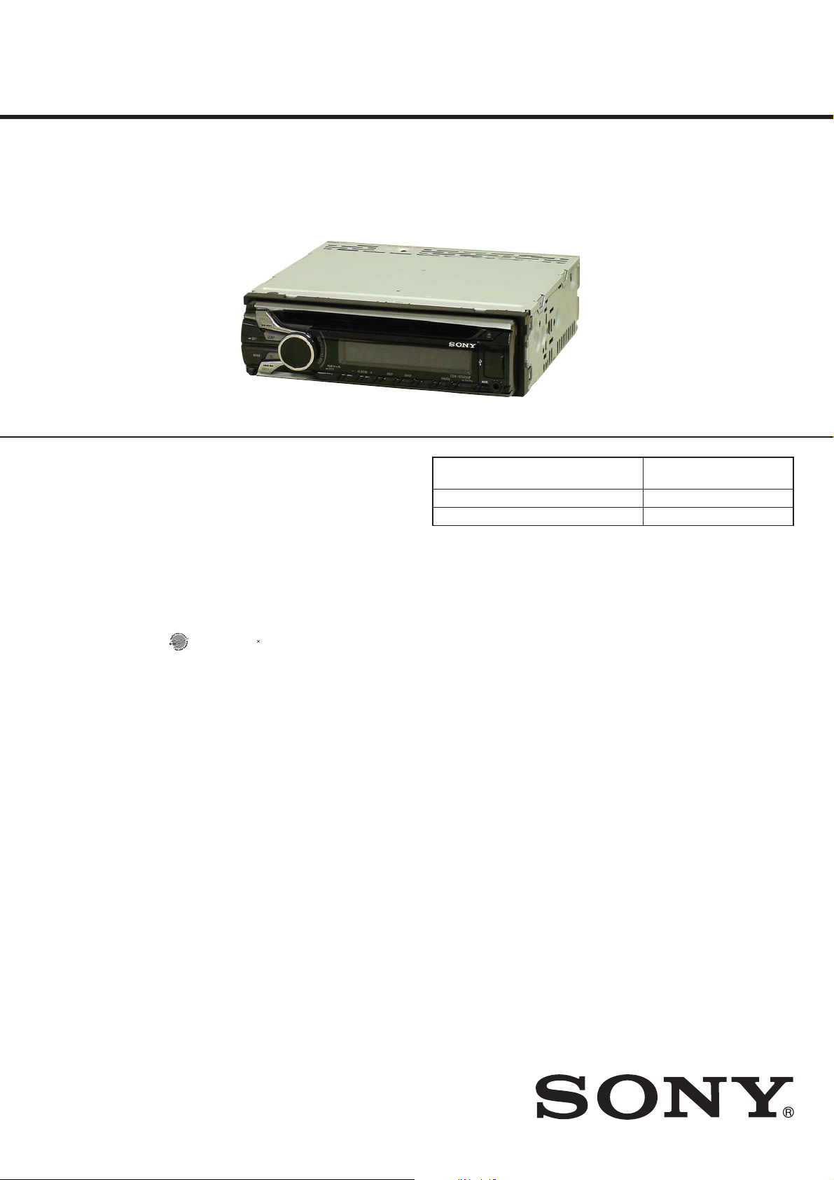
CDX-GT565UP/GT565UV/
GT615UV
SERVICE MANUAL
Ver. 1.3 2013.07
Photo: CDX-GT565UP
• The tuner and CD sections have no adjustments.
SPECIFICATIONS
FOR UNITED STATES CUSTOMERS. NOT
APPLICABLE IN CANADA, INCLUDING
IN THE PROVINCE OF QUEBEC.
POUR LES CONSOMMATEURS AUX
ÉTATS-UNIS. NON APPLICABLE AU
CANADA, Y COMPRIS LA PROVINCE DE
QUÉBEC.
AUDIO POWER SPECIFICATIONS
(GT565UP)
CEA2006 Standard
Power Output: 17 Watts RMS 4 at
4 Ohms < 1% THD+N
SN Ratio: 80 dBA
(reference: 1 Watt into 4 Ohms)
Tuner section (GT565UP)
FM
Tuning range: 87.5 – 107.9 MHz
Antenna (aerial) terminal:
External antenna (aerial) connector
Intermediate frequency: 25 kHz
Usable sensitivity: 8 dBf
Selectivity: 75 dB at 400 kHz
Signal-to-noise ratio: 80 dB (stereo)
Separation: 50 dB at 1 kHz
Frequency response: 20 – 15,000 Hz
AM
Tuning range: 530 – 1,710 kHz
Antenna (aerial) terminal:
External antenna (aerial) connector
Intermediate frequency:
9,115 kHz or 9,125 kHz/5 kHz
Sensitivity: 26 μV
Tuner section
(GT565UV: AEP and UK models)
FM
Tuning range: 87.5 – 108.0 MHz
Antenna (aerial) terminal:
External antenna (aerial) connector
Intermediate frequency: 25 kHz
Usable sensitivity: 8 dBf
Selectivity: 75 dB at 400 kHz
Signal-to-noise ratio: 80 dB (stereo)
Separation: 50 dB at 1 kHz
Frequency response: 20 – 15,000 Hz
MW/LW
Tuning range:
MW: 531 – 1,602 kHz
LW: 153 – 279 kHz
Antenna (aerial) terminal:
External antenna (aerial) connector
Intermediate frequency:
9,124.5 kHz or 9,115.5 kHz/4.5 kHz
Sensitivity: MW: 26 μV, LW: 45 μV
Tuner section
(GT565UV: Russian model)
FM
Tuning range:
FM1/FM2: 87.5 – 108.0 MHz
(at 50 kHz step)
FM3: 65 – 74 MHz
(at 30 kHz step)
Antenna (aerial) terminal:
External antenna (aerial) connector
Intermediate frequency: 25 kHz
Usable sensitivity: 8 dBf
Selectivity: 75 dB at 400 kHz
Signal-to-noise ratio: 80 dB (stereo)
Separation: 50 dB at 1 kHz
Frequency response: 20 – 15,000 Hz
MW/LW
Tuning range:
MW: 531 – 1,602 kHz
LW: 153 – 279 kHz
Antenna (aerial) terminal:
External antenna (aerial) connector
Intermediate frequency:
9,124.5 kHz or 9,115.5 kHz/4.5 kHz
Sensitivity: MW: 26 μV, LW: 45 μV
Tuner section
(GT615UV: E, Mexican and
Korean models)
FM
Tuning range:
87.5 – 108.0 MHz (at 50 kHz step)
87.5 – 108.0 MHz (at 100 kHz step)
87.5 – 107.9 MHz (at 200 kHz step)
FM tuning step: 50 kHz/100 kHz/200 kHz
switchable
Antenna (aerial) terminal:
External antenna (aerial) connector
Intermediate frequency: 25 kHz
Usable sensitivity: 8 dBf
Selectivity: 75 dB at 400 kHz
Signal-to-noise ratio: 80 dB (stereo)
Separation: 50 dB at 1 kHz
Frequency response: 20 – 15,000 Hz
AM
Tuning range:
531 – 1,602 kHz (at 9 kHz step)
530 – 1,710 kHz (at 10 kHz step)
g step: 9 kHz/10 kHz switchable
AM tunin
Antenna (aerial) terminal:
External antenna (aerial) connector
Intermediate frequency:
9,124.5 kHz or 9,115.5 kHz/4.5 kHz
(at 9 kHz step)
9,115 kHz or 9,125 kHz/5 kHz
(at 10 kHz step)
Sensitivity: 26 μV
US Model
Canadian Model
CDX-GT565UP
AEP Model
UK Model
CDX-GT565UV
E Model
CDX-GT615UV
Model Name Using Similar Mechanism
Mechanism Type MG-101CA-188
Optical Pick-up Name DAX-25A
Tuner section
(GT615UV: Saudi Arabia model)
FM
Tuning range: 87.5 – 108.0 MHz
Antenna (aerial) terminal:
External antenna (aerial) connector
Intermediate frequency: 25 kHz
Usable sensitivity: 8 dBf
Selectivity: 75 dB at 400 kHz
Signal-to-noise ratio: 80 dB (stereo)
Separation: 50 dB at 1 kHz
Frequency response: 20 – 15,000 Hz
MW
Tuning range: 531 – 1,602 kHz
Antenna (aerial) terminal:
External antenna (aerial) connector
Intermediate frequency:
9,124.5 kHz or 9,115.5 kHz/4.5 kHz
Sensitivity: 26 μV
SW
Tuning range:
SW1: 2,940 – 7,735 kHz
SW2: 9,500 – 18,135 kHz
(except for 10,140 – 11,575 kHz)
Antenna (aerial) terminal:
External antenna (aerial) connector
Intermediate frequency:
9,124.5 kHz or 9,115.5 kHz/4.5 kHz
Sensitivity: 26 μV
CD Player section
Signal-to-noise ratio: 120 dB
Frequency response: 10 – 20,000 Hz
Wow and utter: Below measurable limit
USB Player section
Interface: USB (Full-speed)
Maximum current: 1 A
Power amplier sectio n
Output: Speaker outputs
Speaker impedance: 4 – 8 ohms
Maximum power output: 52 W u 4 (at 4 ohms)
General
Outputs:
GT565UP/GT615UV:
Audio outputs terminal (front, rear/sub
switchable)
Power antenna (aerial)/Power amplier control
terminal (REM OUT)
GT565UV:
Audio outputs terminal (front, rear/sub
switchable)
Power antenna (aerial) rel
Power amplier control terminal
Inputs:
SiriusXM input terminal (GT565UP)
Remote controller input terminal
Antenna (aerial) inp
AUX input jack (stereo mini jack)
USB signal input connector
Power requirements: 12 V DC car battery
(negative ground (earth))
Dimensions: Approx. 178 u 50 u 179 mm
(7
Mounting dimensions: Approx. 182 u 53 u 162 mm
(7
Mass: Approx. 1.2 kg (2 lb 11 oz)
Supplied accessories:
Remote commander: RM-X211 (GT565UP/GT615UV)
Parts for installation and connections (1 set)
Design and specications are subject to change
without notice.
CDX-GT660UE/GT660UP/
GT660UV/GT710UV
ay control terminal
ut terminal
1
/8 u 2 u 71/8 in) (w/h/d)
1
/4 u 21/8 u 61/2 in) (w/h/d)
US, Canadian, E, Mexican, Korean models
FM/AM COMPACT DISC PLAYER
AEP, UK models
FM/MW/LW COMPACT DISC PLAYER
9-893-266-04
2013G33-1
2013.07
©
Saudi Arabia model
FM/MW/SW COMPACT DISC PLAYER
Sony Corporation
Published by Sony Techno Create Corporation
CDX-GT565UP/GT565UV/GT615UV
For the State of California, USA only
Perchlorate Material – special handling
may apply, See
www.dtsc.ca.gov/hazardouswaste/perchlorate
Perchlorate Material: Lithium battery
contains perchlorate
SiriusXM subscriptions and Satellite Radio
Tuner module sold separately.
www.siriusxm.com.
Sirius, XM and all related marks and logos
are trademarks of Sirius XM Radio Inc.
and its subsidiaries. All other marks and
logos are the property of their respective
owners. All rights reserved.
ZAPPIN and Quick-BrowZer are
trademarks of Sony Corporation.
Windows Media is either a registered
trademark or trademark of Microso
Corporation in the United States and/or
other countries.
is product contains technology subject
to certain intellectual property rights of
Microso. Use or distribution of this
technology outside of this product is
prohibited without the appropriate
license(s) from Microso.
iPhone, iPod, iPod classic, iPod nano, and
iPod touch are trademarks of Apple Inc.,
registered in the U.S. and other countries.
MPEG Layer-3 audio coding technology
and patents licensed from Fraunhofer IIS
and omson.
PANDORA, the PANDORA logo, and the
Pandora trade dress are trademarks or
registered trademarks of Pandora Media,
Inc., used with permission.
CAUTION
Use of controls or adjustments or performance of procedures
other than those specifi ed herein may result in hazardous radia-
tion exposure.
NOTES ON CHIP COMPONENT REPLACEMENT
• Never reuse a disconnected chip component.
• Notice that the minus side of a tantalum capacitor may be damaged by heat.
FLEXIBLE CIRCUIT BOARD REPAIRING
• Keep the temperature of soldering iron around 270 °C during
repairing.
• Do not touch the soldering iron on the same conductor of the
circuit board (within 3 times).
• Be careful not to apply force on the conductor when soldering
or unsoldering.
US and Canadian models:
CAUTION
The use of optical instruments with this
product will increase eye hazard.
x Except US and Canadian models:
This label is located on the bottom of the
chassis.
SAFETY-RELATED COMPONENT WARNING!
COMPONENTS IDENTIFIED BY MARK 0 OR DOTTED LINE
WITH MARK 0 ON THE SCHEMATIC DIAGRAMS AND IN
THE PARTS LIST ARE CRITICAL TO SAFE OPERATION.
REPLACE THESE COMPONENTS WITH SONY PARTS
WHOSE PART NUMBERS APPEAR AS SHOWN IN THIS
MANUAL OR IN SUPPLEMENTS PUBLISHED BY SONY.
ATTENTION AU COMPOSANT AYANT RAPPORT
À LA SÉCURITÉ!
LES COMPOSANTS IDENTIFIÉS PAR UNE MARQUE 0 SUR
LES DIAGRAMMES SCHÉMATIQUES ET LA LISTE DES
PIÈCES SONT CRITIQUES POUR LA SÉCURITÉ DE FONCTIONNEMENT. NE REMPLACER CES COMPOSANTS QUE
PAR DES PIÈCES SONY DONT LES NUMÉROS SONT DONNÉS DANS CE MANUEL OU DANS LES SUPPLÉMENTS
PUBLIÉS PAR SONY.
2
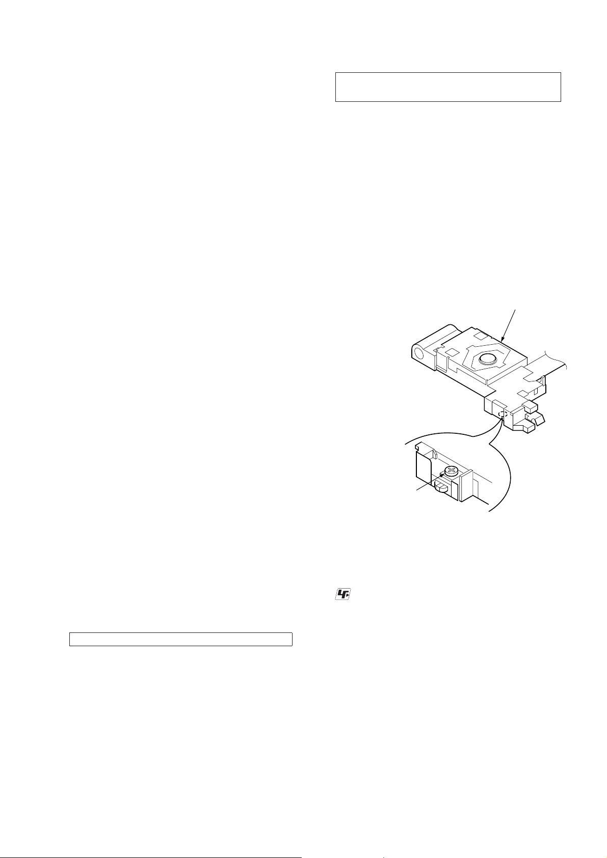
TABLE OF CONTENTS
1. SERVICING NOTES ............................................. 3
2. GENERAL .................................................................. 7
3. DISASSEMBLY
3-1. Disassembly Flow ........................................................... 13
3-2. Cover ............................................................................... 13
3-3. Sub Panel Block .............................................................. 14
3-4. CD Mechanism Deck (MG-101CA-188) ....................... 14
3-5. MAIN Board ................................................................... 15
3-6. SERVO Board ................................................................. 16
3-7. Chassis (T) Sub Assy ...................................................... 17
3-8. Roller Arm Assy .............................................................. 17
3-9. Chassis (OP) Assy ........................................................... 18
3-10. Chucking Arm Sub Assy ................................................. 18
3-11. Sled Motor Assy .............................................................. 19
3-12. Optical Pick-up Section .................................................. 19
3-13. Optical Pick-up ............................................................... 19
4. DIAGRAMS
4-1. Block Diagram - AUDIO INPUT Section - .................... 20
4-2. Block Diagram - AUDIO OUTPUT Section - ................ 21
4-3. Block Diagram
- PANEL, POWER SUPPLY Section - ........................... 22
4-4. Printed Wiring Board - MAIN Section (1/2)
(GT565UP/GT565UV/GT615UV: E, Mexican and Korean
models) - ......................................................................... 24
4-5. Printed Wiring Boards - MAIN Section (2/2)
(GT565UP/GT565UV/GT615UV: E, Mexican and Korean
models) - ......................................................................... 25
4-6. Printed Wiring Board - MAIN Section (1/2)
(GT615UV: Saudi Arabia model) - ................................. 26
4-7. Printed Wiring Boards - MAIN Section (2/2)
(GT615UV: Saudi Arabia model) - ................................. 27
4-8. Schematic Diagram - MAIN Section (1/4) - ................... 28
4-9. Schematic Diagram - MAIN Section (2/4) - ................... 29
4-10. Schematic Diagram - MAIN Section (3/4) - ................... 30
4-11. Schematic Diagram - MAIN Section (4/4) - ................... 31
4-12. Printed Wiring Board - KEY Board -.............................. 32
4-13. Schematic Diagram - KEY Board - ................................ 33
5. EXPLODED VIEWS
5-1. Main Section ................................................................... 42
5-2. Front Panel Section ......................................................... 43
5-3. CD Mechanism Section (MG-101CA-188) .................... 44
6. ELECTRICAL PARTS LIST .............................. 45
Accessories are given in the last of the electrical parts list.
CDX-GT565UP/GT565UV/GT615UV
Ver. 1.1
SECTION 1
SERVICING NOTES
NOTES ON HANDLING THE OPTICAL PICK-UP
BLOCK OR BASE UNIT
The laser diode in the optical pick-up block may suffer electrostatic break-down because of the potential difference generated by
the charged electrostatic load, etc. on clothing and the human body .
During repair, pay attention to electrostatic break-down and also
use the procedure in the printed matter which is included in the
repair parts.
The fl exible board is easily damaged and should be handled with
care.
NOTES ON LASER DIODE EMISSION CHECK
Never look into the laser diode emission from right above when
checking it for adjustment. It is feared that you will lose your sight.
If the optical pick-up block is defective, please replace the whole
optical pick-up block.
Never turn the semi-fi xed resistor located at the side of optical
pick-up block.
optical pick-up
semi-fixed resistor
UNLEADED SOLDER
Boards requiring use of unleaded solder are printed with the leadfree mark (LF) indicating the solder contains no lead.
(Caution: Some printed circuit boards may not come printed with
the lead free mark due to their particular size)
: LEAD FREE MARK
Unleaded solder has the following characteristics.
• Unleaded solder melts at a temperature about 40 °C higher
than ordinary solder.
Ordinary soldering irons can be used but the iron tip has to be
applied to the solder joint for a slightly longer time.
Soldering irons using a temperature regulator should be set to
about 350 °C.
Caution: The printed pattern (copper foil) may peel away if
the heated tip is applied for too long, so be careful!
• Strong viscosity
Unleaded solder is more viscous (sticky, less prone to fl ow)
than ordinary solder so use caution not to let solder bridges
occur such as on IC pins, etc.
• Usable with ordinary solder
It is best to use only unleaded solder but unleaded solder may
also be added to ordinary solder.
3
CDX-GT565UP/GT565UV/GT615UV
Ver. 1.3
DISTINGUISHING OF THE Wal-Mart MODEL
(CDX-GT565UP only)
Confi rm by the part number of the model number label.
– Bottom View –
Part No. (CDX-GT565UP)
Normal model : 4-287-657-0s
Wal-Mart model : 4-470-474-0s
Model number label
NOTE THE MAIN BOARD OR SYSTEM CONTROLLER
(IC501) REPLACING
When the MAIN board or system controller (IC501) is replaced,
the destination setting is necessary.
1. Destination Setting
Set destination according to the procedure below.
1-1. Setting the Destination Code
1. In the state of source off (the clock is displayed), enter the test
mode by pressing the buttons in order of the [4] t [5] t [6]
(press only the [6] button for two seconds).
2. In the state in which the system controller version is displayed
on the liquid crystal display, enter the destination setting mode
by pressing the buttons in order of the [SEEK +] t [SEEK –]
t [PUSH ENTER/SELECT].
3. Input the alphanumeric character of 6 digits of “F XXXXXX”
displayed on the liquid crystal display, and execute the destination setting.
Note: Refer to following “1-3. Entering the Destination Code” for opera-
tion method.
4. The resetting operation is executed by pressing the [SOURCE/
OFF] button for 1 second after the setting ends, and the unit
returns to the normal condition.
1-2. Display in Destination Setting Mode
OP0OP2OP1OP3OP4OP5
12 digits
F
XXXXXX
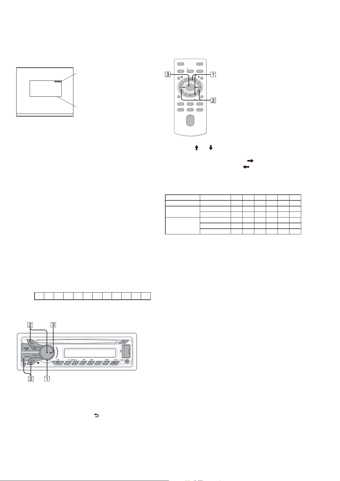
1-3. Entering the Destination Code
• Method of operation by main unit
• Method of operation by remote commander
(GT565UP/GT615UV only)
OFF
SOURCE
PTY
SOUND
ENTER
AT T
MENU
MODE
+
–
DSPL/
SCRL
2
PAUS E
5
+
VO L
–
1. Press the [ ] or [ ] button, and select the alphanumeric character of “0 to F”.
2. The digit advances by pressing the [ ] button.
The digit returns by pressing the [ ] button.
3. The setting is completed by pressing the [ENTER] button, and
the initialization operation is done.
1-4. Destination Code
Model Destination OP5 OP4 OP3 OP2 OP1 OP0
CDX-GT565UP US, Canadian 0 3 C 0 2 2
CDX-GT565UV
AEP, UK 0 1 C 0 0 1
Russian 0 1 E 0 0 7
E, Korean 0 1 C 8 1 0
CDX-GT615UV
Saudi Arabia 0 1 C 8 1 4
Mexican 0 1 C 8 1 0
2. Confi rmation After Destination Setting
Execute the following operation after completing the destination
setting, and confi rm a correct destination was set.
Destination setting checking method:
1. In the state of source off (the clock is displayed on the liquid
crystal display), enter the test mode by pressing the buttons in
order of the [4] t [5] t [6] (press only the [6] button for two
seconds).
2. In the state in which the system controller version is displayed
on the liquid crystal display, enter the destination setting value
display mode by pressing the [DSPL] button.
3. Confi rm the alphanumeric character of 6 digits of “F
XXXXXX” displayed in liquid crystal display is an value correctly input.
4. The resetting operation is executed by pressing the [SOURCE/
OFF] button for 1 second after the confi rming ends, and the
unit returns to the normal condition.
1. Rotate the control dial, and select the alphanumeric character
of “0 to F”.
2. The digit advances by pressing the [PUSH ENTER/SELECT]
or [SEEK +] button.
The digit returns by pressing the [ ] or [SEEK –] button.
3. The setting is completed by pressing the [PUSH ENTER/
SELECT] button, and the initialization operation is done.
4
CDX-GT565UP/GT565UV/GT615UV
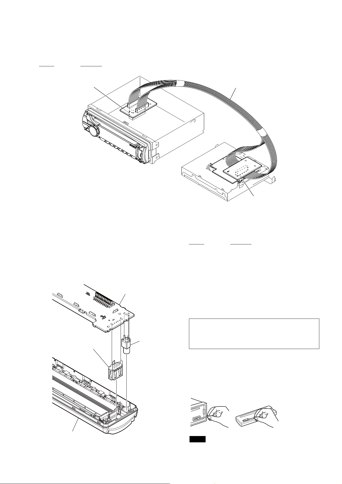
EXTENSION CABLE AND SERVICE POSITION
When repairing or servicing this set, connect the jig cable (extension cable (CD mecha)) as shown below.
• Connect the MAIN board (CN700) and the SERVO board (CN401) with the jig cable.
Jig cable:
Part No. Description
A-1818-424-A EXTENSION CABLE (CD MECHA)
MAIN board
(CN700)
extension cable (CD mecha)
Ver. 1.2
NOTE FOR REPLACEMENT OF THE USB CONNECTOR (CN971) AND THE AUX JACK (J901)
To replace the USB connector and the AUX jack requires alignment.
1. Insert the USB connector and the AUX jack into the front panel.
2. Place the KEY board on the front panel and align the terminals
of the USB connector and the AUX jack with the holes in the
KEY board.
3. Solder seven terminals of the connector and three terminals of
the jack.
KEY board
AUX jack
USB (socket) connector
SERVO board
(CN401)
TEST DISCS
Use following TEST DISC (for CD) when this set confi rms the
operation and checks it.
Part No. Description
3-702-101-01 DISC (YEDS-18), TEST
4-225-203-01 DISC (PATD-012), TEST
NOTE FOR REPLACEMENT OF THE SERVO BOARD
When repairing, the complete SERVO board should be replaced
since any parts in the SERVO board cannot be repaired.
NOTE FOR REPLACEMENT OF THE SENSOR BOARD
When the SENSOR board is defective, exchange the MECHANICAL BLOCK (Z) ASSY 08 (Former type) or MECHANICAL
BLOCK (11CA) ASSY (New type).
Note: As for the mechanism deck (MG-101CA-188) carried in this
unit, component parts have been changed from the midway
of production. When you perform repair exchange of the
mechanism deck (MG-101CA-188), refer to “ABOUT THE
MG-101CA-188 OF FORMER AND NEW” on page 6.
CLEANING THE CONNECTORS
e unit may not function properly if the connectors
between the unit and the front panel are not clean. In order
to prevent this, detach the front panel and clean the
connectors with a cotton swab. Do not apply too much force.
Otherwise, the connectors may be damaged.
front panel
Notes
t For safety, turn o the ignition before cleaning the connectors,
and remove the key from the ignition switch.
t Never touch the connectors directly with your ngers or with
any metal device.
5
CDX-GT565UP/GT565UV/GT615UV
Ver. 1.2
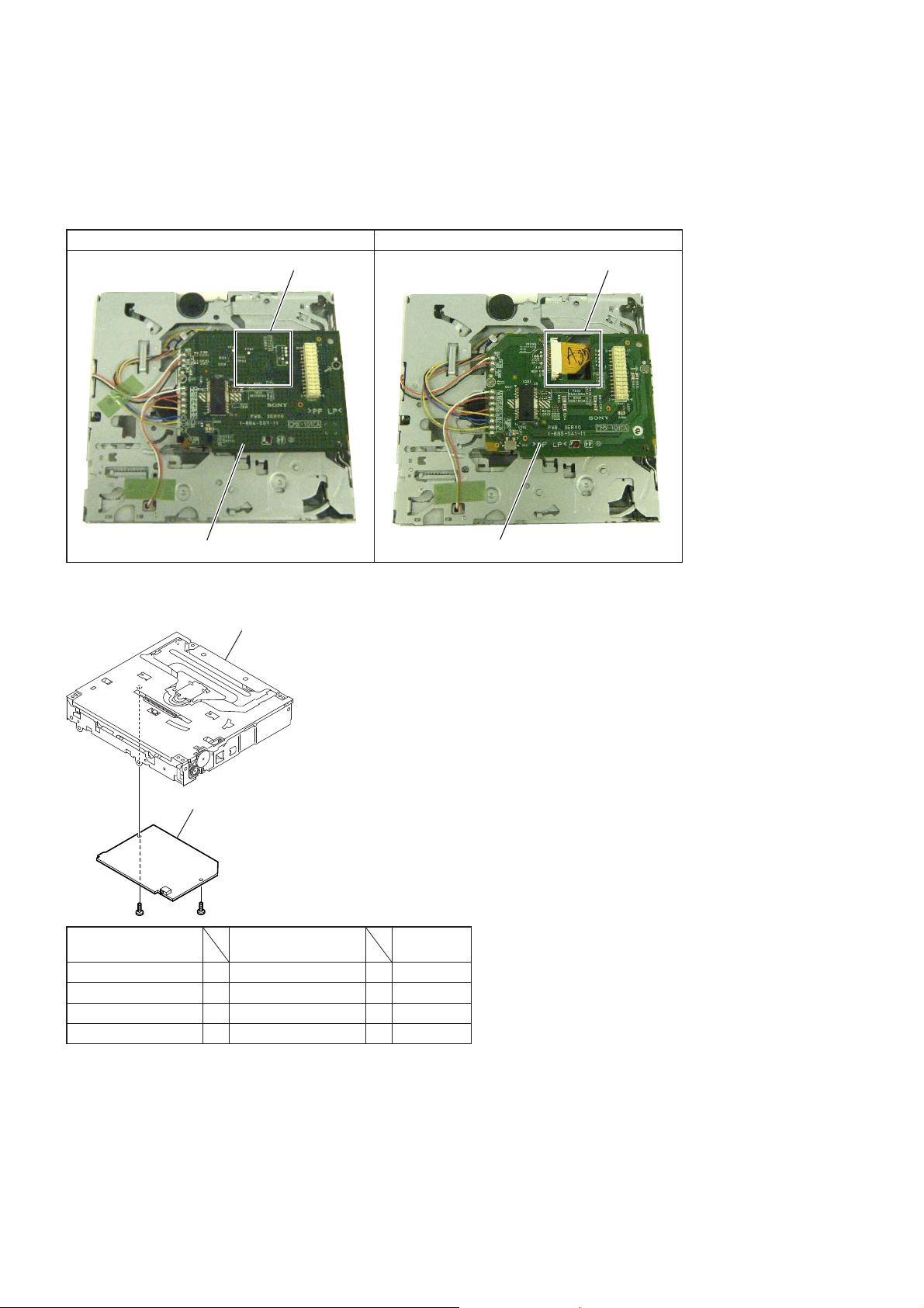
ABOUT THE MG-101CA-188 OF FORMER AND NEW
As for the mechanism deck (MG-101CA-188) carried in this unit, component parts have been changed from the midway of production.
When you perform repair exchange of the mechanism deck (MG-101CA-188), please be sure to work, after referring to the following fi gure
and checking former and new.
• New/Former Discrimination
As shown in the following fi gure, please check the SERVO board side of the mechanism deck (MG-101CA-188).
Former type New type
Flexible board cannot be seen.
Flexible board can be seen.
SERVO board (double-sided board)
• New/Former Compatibility
Mechanical block assy
Complete SERVO board
MECHANICAL
BLOCK ASSY
New type + New type = OK
New type + Former type = OK
Former type + New type = NG
Former type + Former type = OK
COMPLETE SERVO
BOARD
SERVO board (one side board)
Judgment
6
SECTION 2
GENERAL
This section is extracted
from instruction manual.
CDX-GT565UP/GT565UV/GT615UV
Ver. 1.3
(CDX-GT565UP for Normal model)
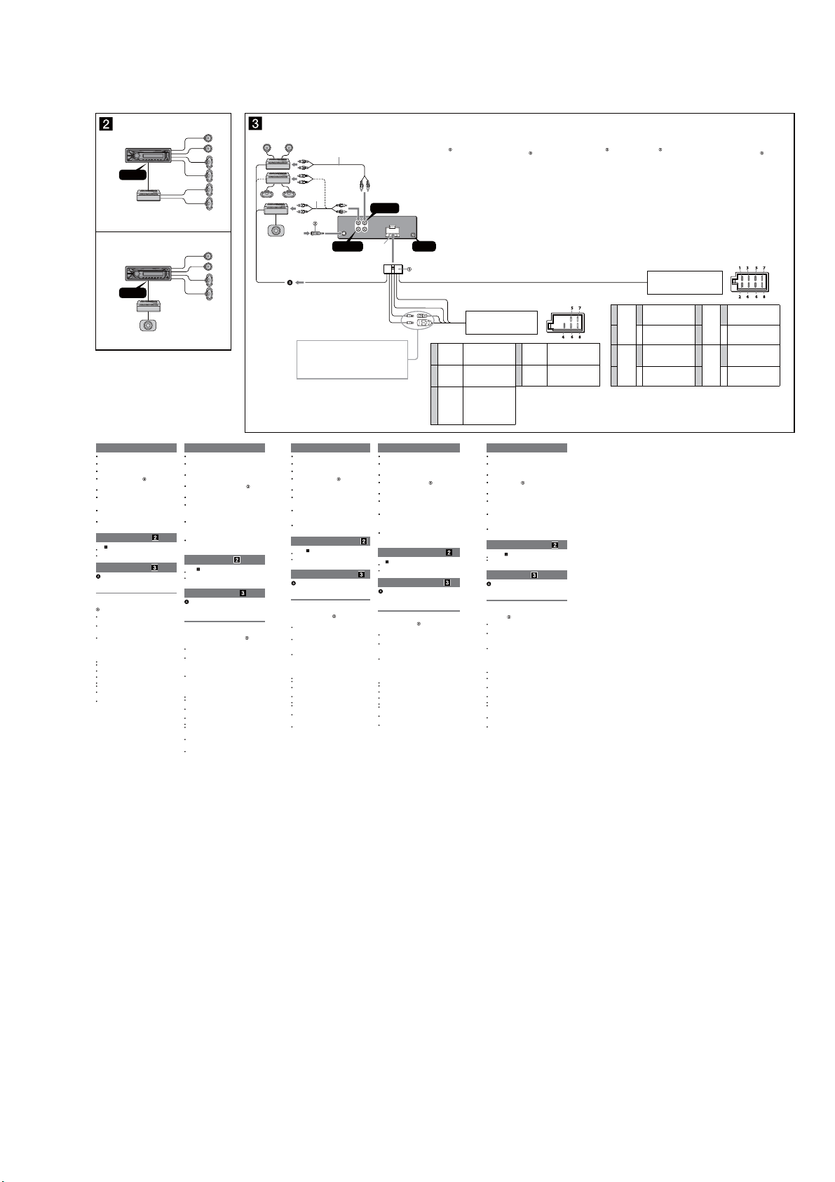
A
FRONT
AUDIO OUT
REAR / SUB
AUDIO OUT
B
Satellite radio tuner
(SiriusXM)*
Syntoniseur radio satellite
(SiriusXM)*
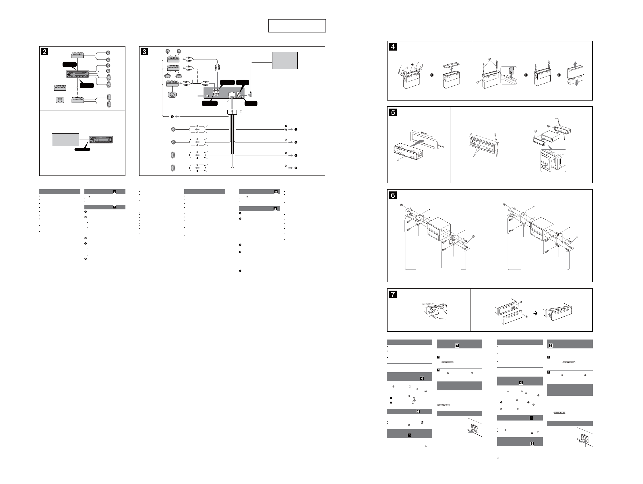
Cautions
is unit is designed for negative ground (earth) 12 V
DC operation only.
Do not get the leads under a screw, or caught in moving
parts (e.g. seat railing).
Before making connections, turn the car ignition off to
avoid short circuits.
Connect the yellow and red power supply leads only
after all other leads have been connected.
Run all ground (earth) leads to a common ground
(earth) point.
Be sure to insulate any loose unconnected leads with
electrical tape for safety.
e use of optical instruments with this product will
increase eye hazard.
Notes on the power supply lead (yellow)
When connecting this unit in combination with other
stereo components, the connected car circuit’s rating
must be higher than the sum of each component’s fuse.
When no car circuits are rated high enough, connect
the unit directly to the battery.
SIRIUSXM IN
* not supplied
non fourni
Connection example
Notes ( -A)
Be sure to connect the ground (earth) lead before connecting the
amplier.
The alarm will only sound if the built-in amplier is used.
Connection diagram
To a metal surface of the car
First connect the black ground (earth) lead, then connect the yellow
and red power supply leads.
To the power antenna (aerial) control lead or
power supply lead of antenna (aerial) booster
Notes
It is not necessary to connect this lead if there is no power
antenna (aerial) or antenna (aerial) booster, or with a
manually-operated telescopic antenna (aerial).
When your car has a built-in FM/AM antenna (aerial) in the rear/
side glass, see “Notes on the control and power supply leads.”
To AMP REMOTE IN of an optional power
amplier
This connection is only for ampliers. Connecting any other system
may damage the unit.
To a car’s illumination signal
Be sure to connect the black ground (earth) lead to a metal surface
of the car rst.
To the +12 V power terminal which is energized
in the accessory position of the ignition switch
Notes
If there is no accessory position, connect to the +12 V power
(battery) terminal which is energized at all times.
Be sure to connect the black ground (earth) lead to a metal
surface of the car rst.
When your car has a built-in FM/AM antenna (aerial) in the rear/
side glass, see “Notes on the control and power supply leads.”
To the +12 V power terminal which is energized
at all times
Be sure to connect the black ground (earth) lead to a metal surface
of the car rst.
Left
Gauche
Right
Droit
Left
Gauche
Right
Droit
Notes on the control and power supply leads
REM OUT lead (blue/white striped) supplies +12 V DC when you turn
on the unit.
When your car has built-in FM/AM antenna (aerial) in the rear/side
glass, connect REM OUT lead (blue/white striped) or the accessory
power supply lead (red) to the power terminal of the existing antenna
(aerial) booster. For details, consult your dealer.
A power antenna (aerial) without a relay box cannot be used with this
unit.
Memory hold connection
When the yellow power supply lead is connected, power will always be
supplied to the memory circuit even when the ignition switch is turned
o.
Notes on speaker connection
Before connecting the speakers, turn the unit o.
Use speakers with an impedance of 4 to 8 ohms, and with adequate
power handling capacities to avoid its damage.
Do not connect the speaker terminals to the car chassis, or connect the
terminals of the right speakers with those of the left speaker.
Do not connect the ground (earth) lead of this unit to the negative (–)
terminal of the speaker.
Do not attempt to connect the speakers in parallel.
Connect only passive speakers. Connecting active speakers (with
built-in ampliers) to the speaker terminals may damage the unit.
To avoid a malfunction, do not use the built-in speaker leads installed
in your car if the unit shares a common negative (–) lead for the right
and left speakers.
Do not connect the unit’s speaker leads to each other.
Note on connection
If speaker and amplier are not connected correctly, “FAILURE” appears
in the display. In this case, make sure the speaker and amplier are
connected correctly.
1
*
from car antenna (aerial)
à partir de l’antenne du
véhicule
REMOTE
Max. supply current 0.4 A
Courant max. fourni 0,4 A
Précautions
Cet appareil est exclusivement conçu pour fonctionner
sur une tension de 12 V CC avec masse négative.
Évitez de xer des vis sur les câbles ou de coincer ceux-ci
dans des pièces mobiles (par exemple, armature de siège).
Avant d’eectuer les raccordements, coupez le moteur
pour éviter un court-circuit.
Raccordez les câbles d’alimentation jaune et rouge
seulement après avoir terminé tous les autres
raccordements.
Rassemblez tous les câbles de mise à la masse en
un point de masse commun.
Pour des raisons de sécurité, veillez à isoler avec du
ruban isolant tout câble libre non raccordé.
L’utilisation d’instruments optiques avec ce produit
augmente les risques pour les yeux.
Remarques sur le câble d’alimentation (jaune)
Lorsque cet appareil est raccordé à d’autres éléments
stéréo, la valeur nominale du circuit de la voiture
raccordé doit être supérieure à la somme des fusibles de
chaque élément.
Si aucun circuit de la voiture n’est assez puissant,
raccordez directement l’appareil à la batterie.
REAR / SUB
AUDIO OUT
Blue/white striped
Rayé bleu/blanc
1
*
REAR/SUB FRONT
AUDIO OUT
2
*
White
Blanc
White/black striped
Rayé blanc/noir
Gray
Gris
Gray/black striped
Rayé gris/noir
Green
Vert
Green/black striped
Rayé vert/noir
Purple
Violet
Purple/black striped
Rayé violet/noir
FRONT
AUDIO OUT
L
R
Fuse (10 A)
Fusible (10 A)
Satellite radio tuner
Syntoniseur radio satellite
SIRIUSXM
IN
REMOTE
3
*
IN
Black
Noir
Orange/white striped
Rayé orange/blanc ILLUMINATION
Red
Rouge ACC
Yellow
Jaune BATTERY
Exemple de raccordement
Remarques ( -A)
Raccordez d’abord le câble de mise à la masse avant de raccorder
l’amplicateur.
L’alarme est émise uniquement lorsque l’amplicateur intégré est
utilisé.
Schéma de raccordement
À un point métallique de la voiture
Branchez d’abord le câble de mise à la masse noir et, ensuite, les
câbles d’alimentation jaune et rouge.
Au câble de commande d’antenne électrique ou
au câble d’alimentation de l’amplicateur
d’antenne
Remarques
Il n’est pas nécessaire de raccorder ce câble s’il n’y a pas d’antenne
électrique ni d’amplicateur d’antenne, ou avec une antenne
télescopique manuelle.
Si votre voiture est équipée d’une antenne FM/AM intégrée dans
la vitre arrière/latérale, voir « Remarques sur les câbles de
commande et d’alimentation ».
Au niveau de AMP REMOTE IN de l’amplicateur
de puissance en option
Ce raccordement s’applique uniquement aux amplicateurs. Le
branchement de tout autre système risque d’endommager
l’appareil.
Vers le connecteur du signal d’éclairage de la
voiture
Raccordez d’abord le câble de mise à la masse noir à un point
métallique du véhicule.
À la borne d’alimentation +12 V qui est
alimentée quand la clé de contact est sur la
position accessoires
Remarques
S’il n’y a pas de position accessoires, raccordez la borne
d’alimentation (batterie) +12 V qui est alimentée en permanence.
Raccordez d’abord le câble de mise à la masse noir à un point
métallique du véhicule.
Si votre voiture est équipée d’une antenne FM/AM intégrée dans
la vitre arrière/latérale, voir « Remarques sur les câbles de
commande et d’alimentation ».
À la borne d’alimentation +12 V qui est
alimentée en permanence
Raccordez d’abord le câble de mise à la masse noir à un point
métallique du véhicule.
4
(
SiriusXM
)*
4
(
SiriusXM
)*
1
RCA pin cord (not supplied)
*
2
*
AUDIO OUT can be switched SUB or REAR. For
details, see the supplied Operating Instructions.
3
*
Separate adaptor may be required.
4
*
not supplied
1
*
Cordon à broche RCA (non fourni)
2
*
AUDIO OUT peut être commuté sur SUB ou
REAR. Pour obtenir plus de détails, reportez-vous
au mode d’emploi fourni.
3
L’utilisation d’un adaptateur pourrait être
*
nécessaire.
4
non fourni
*
Remarques sur les câbles de commande et d’alimentation
Le câble REM OUT (rayé bleu/blanc) fournit une alimentation de +12 V
CC lorsque vous mettez l’appareil en marche.
Lorsque votre voiture est équipée d’une antenne FM/AM intégrée dans
la vitre arrière/latérale, raccordez le câble REM OUT (rayé bleu/blanc)
ou le câble d’alimentation des accessoires (rouge) à la borne
d’alimentation de l’amplicateur d’antenne existant. Pour plus de
détails, consultez votre détaillant.
Une antenne électrique sans boîtier de relais ne peut pas être utilisée
avec cet appareil.
Raccordement pour la conservation de la mémoire
Lorsque le câble d’alimentation jaune est raccordé, le circuit de la
mémoire est alimenté en permanence même si la clé de contact est sur la
position d’arrêt.
Remarques sur le raccordement des haut-parleurs
Avant de raccorder les haut-parleurs, éteignez l'appareil.
Utilisez des haut-parleurs ayant une impédance de 4 à 8 ohms avec
une capacité électrique adéquate pour éviter de les endommager.
Ne raccordez pas les bornes du système de haut-parleurs au châssis de
la voiture et ne raccordez pas les bornes du haut-parleur droit à celles
du haut-parleur gauche.
Ne raccordez pas le câble de mise à la masse de cet appareil à la borne
négative (–) du haut-parleur.
N’essayez pas de raccorder les haut-parleurs en parallèle.
Raccordez uniquement des haut-parleurs passifs. Le raccordement de
haut-parleurs actifs (avec amplicateurs intégrés) aux bornes des
haut-parleurs peut endommager l’appareil.
Pour éviter tout problème de fonctionnement, n’utilisez pas les câbles
des haut-parleurs intégrés installés dans votre voiture si l’appareil
possède un câble négatif commun (–) pour les haut-parleurs droit et
gauche.
Ne raccordez pas entre eux les câbles des haut-parleurs de l’appareil.
Remarque sur le raccordement
Si le haut-parleur et l’amplicateur ne sont pas raccordés correctement,
le message « FAILURE » s’ache. Dans ce cas, assurez-vous que les
haut-parleurs et l’amplicateur sont bien raccordés.
12
Face the hook inwards.
Tournez le crochet vers
l’intérieur.
1 23
Claws
Gries
size
5 × max. 8 mm
7
(
/32 × max. 5/16 in)
dimension
5 × max. 8 mm
7
(
/32 × 5/16 po max.)
A TOYOTA
Bracket
Support
Existing parts supplied with your car
Pièces existantes fournies avec la voiture
to dashboard/center console
vers le tableau de bord/la console centrale
size
5 × max. 8 mm
7
(
/32 × max. 5/16 in)
dimension
5 × max. 8 mm
7
(
/32 × 5/16 po max.)
Bracket
Support
B NISSAN
size
5 × max. 8 mm
7
(
/32 × max. 5/16 in)
dimension
5 × max. 8 mm
7
(
/32 × 5/16 po max.)
Bracket
Support
Dashboard
Tableau de bord
Existing parts supplied with your car
Pièces existantes fournies avec la voiture
to dashboard/center console
vers le tableau de bord/la console centrale
size
5 × max. 8 mm
7
/32 × max. 5/16 in)
(
dimension
5 × max. 8 mm
7
/32 × 5/16 po max.)
(
Bracket
Support
Note: Refer to “DISTINGUISHING OF THE Wal-Mart MODEL” on
page 4 for Normal model.
CDX-GT565UP/GT565UV/GT615UV
AB
Front panel release button
Touche de déverrouillage
de la façade
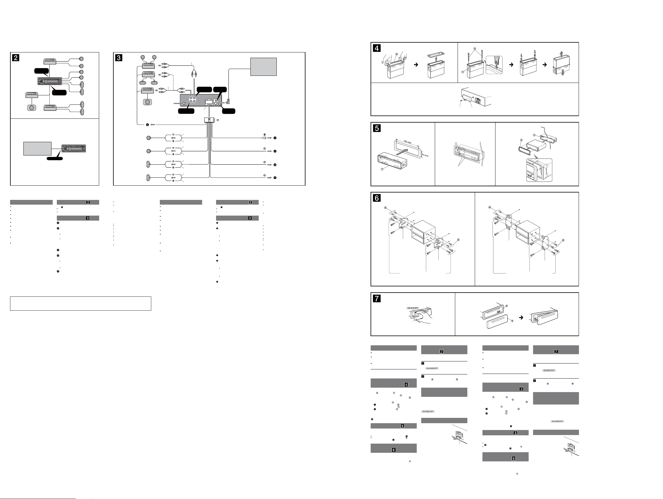
Precautions
Choose the installation location carefully so that the
unit will not interfere with normal driving operations.
Avoid installing the unit in areas subject to dust, dirt,
excessive vibration, or high temperatures, such as in
direct sunlight or near heater ducts.
Use only the supplied mounting hardware for a safe and
secure installation.
Mounting angle adjustment
Adjust the mounting angle to less than 45°.
Removing the protection
collar and the bracket
Before installing the unit, remove the protection
and the bracket from the unit.
collar
Remove the protection collar .
1
Pinch both edges of the protection collar , then
pull it out.
Remove the bracket .
2
Insert both release keys together between
the unit and the bracket
Pull down the bracket , then pull up the unit
to separate.
until they click.
Mounting example
Installation in the dashboard
Notes
Bend these claws outward for a tight t, if necessary ( -2).
Make sure that the 4 catches on the protection collar are properly
engaged in the slots of the unit (
Mounting the unit in a
Japanese car
You may not be able to install this unit in some makes of
Japanese cars. In such a case, consult your Sony dealer.
Note
To prevent malfunction, install only with the supplied screws
-3).
.
How to detach and attach the
front panel
Before installing the unit, detach the front panel.
-A To detach
Before detaching the front panel, be sure to press and
hold
button, and pull it off towards you.
Engage part of the front panel with part of the unit,
as illustrated, and push the le side into position until it
clicks.
Be sure to set the Auto Off function. For details, see the
supplied Operating Instructions.
e unit will shut off completely and automatically in the
set time aer the unit is turned off, which prevents
battery drain.
If you do not set the Auto Off function, press and hold
you turn the ignition off.
When replacing the fuse, be sure to
use one matching the amperage
rating stated on the original fuse. If
the fuse blows, check the power
connection and replace the fuse. If
the fuse blows again after
replacement, there may be an
internal malfunction. In such a case,
consult your nearest Sony dealer.
. Press the front panel release
-B To attach
Warning if your car’s ignition
has no ACC position
until the display disappears each time
Fuse replacement
Fuse (10 A)
Précautions
Choisissez soigneusement l’emplacement d’installation
pour que l’appareil ne gêne pas le conducteur pendant
la conduite.
Évitez d’installer l’appareil dans un endroit exposé à la
poussière, à la saleté, à des vibrations excessives ou à
des températures élevées comme en plein soleil ou à
proximité de conduits de chauage.
Pour garantir un montage sûr, n’utilisez que le matériel
fourni.
Réglage de l’angle de montage
Réglez l’inclinaison à un angle inférieur à 45°.
Retrait du tour de protection
et du support
Avant d’installer l’appareil, retirez le tour de
et le support de l’appareil.
protection
Retirez le tour de protection .
1
Pincez les deux bords du tour de protection ,
puis sortez-le.
Retirez le support .
2
Insérez les clés de déblocage en même
temps entre l’appareil et le support
déclic.
Tirez le support vers le bas, puis tirez sur
l’appareil vers le haut pour les séparer.
jusqu’au
Exemple de montage
Installation dans le tableau de bord
Remarques
Si nécessaire, pliez ces gries vers l’extérieur pour assurer une prise
correcte (
-2).
Assurez-vous que les 4 loquets situés sur le tour de protection sont
correctement engagés dans les fentes de l’appareil (
Montage de l’appareil dans
une voiture japonaise
Cet appareil ne peut pas être installé dans certaines
voitures japonaises. Consultez, dans ce cas, votre
détaillant Sony.
Remarque
Pour éviter tout problème de fonctionnement, utilisez uniquement les vis
fournies pour le montage.
-3).
Retrait et xation de la façade
Avant d’installer l’appareil, retirez la façade.
-A Pour la retirer
Avant de retirer la façade, n’oubliez pas de maintenir
enfoncée la touche
touche de déverrouillage de la façade, puis faites glisser la
façade vers vous.
-B Pour la xer
Engagez la partie de la façade dans la partie de
l’appareil, comme illustré, puis appuyez sur le côté gauche
jusqu’au déclic indiquant que la façade est en position.
Avertissement si le contact de
votre véhicule ne comporte
pas de position ACC
Veillez à régler la fonction Auto Off. Pour obtenir
davantage d’informations, reportez-vous au mode
d’emploi fourni.
L’appareil s’éteint complètement et automatiquement
après le laps de temps choisi une fois l’appareil arrêté afin
d’éviter que la batterie ne se décharge.
Si vous ne réglez pas la fonction Auto Off, appuyez sur la
touche
ce que l’achage disparaisse à chaque fois que vous
coupez le contact.
Remplacement du fusible
Lorsque vous remplacez le fusible,
veillez à utiliser un fusible dont
l’intensité, en ampères, correspond à
la valeur indiquée sur le fusible
usagé. Si le fusible grille, vériez le
branchement de l’alimentation et
remplacez le fusible. Si le nouveau
fusible grille également, il est
possible que l’appareil soit
défectueux. Dans ce cas, consultez
votre détaillant Sony le plus proche.
. Appuyez sur la
et maintenez-la enfoncée jusqu’à
Fusible (10 A)
77
CDX-GT565UP/GT565UV/GT615UV
Ver. 1.3
(CDX-GT565UP for Wal-Mart model)
A
FRONT
AUDIO OUT
REAR / SUB
AUDIO OUT
B
Satellite radio tuner
(SiriusXM)*
Sintonizador de radio por satélite
(SiriusXM)*
Cautions
is unit is designed for negative ground (earth) 12 V
DC operation only.
Do not get the leads under a screw, or caught in moving
parts (e.g. seat railing).
Before making connections, turn the car ignition off to
avoid short circuits.
Connect the yellow and red power supply leads only
after all other leads have been connected.
Run all ground (earth) leads to a common ground
(earth) point.
Be sure to insulate any loose unconnected leads with
electrical tape for safety.
e use of optical instruments with this product will
increase eye hazard.
Notes on the power supply lead (yellow)
When connecting this unit in combination with other
stereo components, the connected car circuit’s rating
must be higher than the sum of each component’s fuse.
When no car circuits are rated high enough, connect
the unit directly to the battery.
SIRIUSXM IN
* not supplied
no suministrado
Connection example
Notes ( -A)
Be sure to connect the ground (earth) lead before connecting the
amplier.
The alarm will only sound if the built-in amplier is used.
Connection diagram
To a metal surface of the car
First connect the black ground (earth) lead, then connect the yellow
and red power supply leads.
To the power antenna (aerial) control lead or
power supply lead of antenna (aerial) booster
Notes
It is not necessary to connect this lead if there is no power
antenna (aerial) or antenna (aerial) booster, or with a
manually-operated telescopic antenna (aerial).
When your car has a built-in FM/AM antenna (aerial) in the rear/
side glass, see “Notes on the control and power supply leads.”
To AMP REMOTE IN of an optional power
amplier
This connection is only for ampliers and a power antenna (aerial).
Connecting any other system may damage the unit.
To a car’s illumination signal
Be sure to connect the black ground (earth) lead to a metal surface
of the car rst.
To the +12 V power terminal which is energized
in the accessory position of the ignition switch
Notes
If there is no accessory position, connect to the +12 V power
(battery) terminal which is energized at all times.
Be sure to connect the black ground (earth) lead to a metal
surface of the car rst.
When your car has a built-in FM/AM antenna (aerial) in the rear/
side glass, see “Notes on the control and power supply leads.”
To the +12 V power terminal which is energized
at all times
Be sure to connect the black ground (earth) lead to a metal surface
of the car rst.
Left
Izquierdo
Right
Derecho
Left
Izquierdo
Right
Derecho
Notes on the control and power supply leads
REM OUT lead (blue/white striped) supplies +12 V DC when you turn
on the unit.
When your car has built-in FM/AM antenna (aerial) in the rear/side
glass, connect REM OUT lead (blue/white striped) or the accessory
power supply lead (red) to the power terminal of the existing antenna
(aerial) booster. For details, consult your dealer.
A power antenna (aerial) without a relay box cannot be used with this
unit.
Memory hold connection
When the yellow power supply lead is connected, power will always be
supplied to the memory circuit even when the ignition switch is turned
o.
Notes on speaker connection
Before connecting the speakers, turn the unit o.
Use speakers with an impedance of 4 to 8 ohms, and with adequate
power handling capacities to avoid its damage.
Do not connect the speaker terminals to the car chassis, or connect the
terminals of the right speakers with those of the left speaker.
Do not connect the ground (earth) lead of this unit to the negative (–)
terminal of the speaker.
Do not attempt to connect the speakers in parallel.
Connect only passive speakers. Connecting active speakers (with
built-in ampliers) to the speaker terminals may damage the unit.
To avoid a malfunction, do not use the built-in speaker leads installed
in your car if the unit shares a common negative (–) lead for the right
and left speakers.
Do not connect the unit’s speaker leads to each other.
Note on connection
If speaker and amplier are not connected correctly, “FAILURE” appears
in the display. In this case, make sure the speaker and amplier are
connected correctly.
1
*
from car antenna (aerial)
desde la antena del
automóvil
REM OUT
Max. supply current 0.4 A
Corriente máx. de alimentación
de 0,4 A
Precauciones
Esta unidad ha sido diseñada para alimentarse sólo con
cc de 12 V de masa negativa.
No coloque los cables debajo de ningún tornillo, ni los
aprisione con partes móviles (p. ej. los rieles del
asiento).
Antes de realizar las conexiones, apague el automóvil
para evitar cortocircuitos.
Conecte los cables de fuente de alimentación amarillo
y rojo solamente después de haber conectado los
demás.
Conecte todos los cables de conexión a masa a un
punto común.
Por razones de seguridad, asegúrese de aislar con cinta
aislante los cables sueltos que no estén conectados.
El uso de instrumentos ópticos con este producto
aumenta el riesgo de sufrir daños oculares.
Notas sobre el cable de fuente de alimentación
(amarillo)
Cuando conecte esta unidad en combinación con otros
componentes estéreo, la capacidad nominal del circuito
conectado del automóvil debe ser superior a la suma del
fusible de cada componente.
Si no hay circuitos del automóvil con capacidad
nominal suficientemente alta, conecte la unidad
directamente a la batería.
REAR / SUB
AUDIO OUT
1
*
FRONT
AUDIO OUT
L
R
REAR/SUB FRONT
AUDIO OUT
Fuse (10 A)
2
*
Fusible (10 A)
Blue/white striped
Con rayas azules y
blancas
White
Blanco
White/black striped
Con rayas blancas y negras
Gray
Gris
Gray/black striped
Con rayas grises y negras
Green
Verde
Green/black striped
Con rayas verdes y negras
Purple
Morado
Purple/black striped
Con rayas moradas y negras
Satellite radio tuner
Sintonizador de radio por satélite
SIRIUSXM
IN
REMOTE
3
*
IN
Black
Negro
Orange/white striped
Con rayas naranjas y blancas ILLUMINATION
Red
Rojo ACC
Yellow
Amarillo BATTERY
Ejemplo de conexiones
Notas ( -A)
Asegúrese de conectar primero el cable de conexión a masa antes de
realizar la conexión del amplicador.
La alarma sonará únicamente si se utiliza el amplicador incorporado.
Diagrama de conexión
A una supercie metálica del automóvil
Conecte primero el cable de conexión a masa negro, y después los
cables amarillo y rojo de fuente de alimentación.
Al cable de control de la antena motorizada o al
cable de fuente de alimentación del
amplicador de señal de la antena
Notas
Si no se dispone de antena motorizada ni de amplicador de
señal de la antena, o se utiliza una antena telescópica accionada
manualmente, no será necesario conectar este cable.
Si el automóvil tiene una antena de FM/AM incorporada en el
cristal trasero o lateral, consulte “Notas sobre los cables de
control y de fuente de alimentación”.
A AMP REMOTE IN de un amplicador de
potencia opcional
Esta conexión es sólo para amplicadores y una antena
motorizada. La conexión de cualquier otro sistema puede dañar la
unidad.
A una señal de iluminación del automóvil
Asegúrese de conectar primero el cable de conexión a masa negro a
una supercie metálica del automóvil.
Al terminal de alimentación de +12 V que recibe
energía en la posición de accesorio del
interruptor de encendido
Notas
Si no hay posición de accesorio, conéctelo al terminal de
alimentación (batería) de +12 V que recibe energía sin
interrupción.
Asegúrese de conectar primero el cable de conexión a masa
negro a una supercie metálica del automóvil.
Si el automóvil tiene una antena de FM/AM incorporada en el
cristal trasero o lateral, consulte “Notas sobre los cables de
control y de fuente de alimentación”.
Al terminal de alimentación de +12 V que recibe
energía sin interrupción
Asegúrese de conectar primero el cable de conexión a masa negro a
una supercie metálica del automóvil.
4
SiriusXM
(
)*
4
*
(SiriusXM)
1
*
RCA pin cord (not supplied)
2
*
AUDIO OUT can be switched SUB or REAR. For
details, see the supplied Operating Instructions.
3
*
Separate adaptor may be required.
4
*
not supplied
1
*
Cable con terminales RCA (no suministrado)
2
*
AUDIO OUT (salida de audio) puede cambiarse a
SUB o REAR. Para obtener informacion, consulte
el manual de instrucciones suministrado.
3
Puede requerirse un adaptador independiente.
*
4
*
no suministrado
Notas sobre los cables de control y de fuente de alimentación
El cable REM OUT (rayado azul y blanco) suministra cc +12 V al
encender la unidad.
Si el automóvil dispone de una antena de FM/AM incorporada en el
cristal trasero o lateral, conecte el cable REM OUT (rayado azul y
blanco) o el cable de fuente de alimentación auxiliar (rojo) al terminal
de alimentación del amplicador de señal de la antena existente. Para
obtener más detalles, consulte a su distribuidor.
Con esta unidad no es posible utilizar una antena motorizada sin caja
de relé.
Conexión para protección de la memoria
Si conecta el cable de fuente de alimentación amarillo, el circuito de la
memoria recibirá siempre alimentación, aunque apague el interruptor
de encendido.
Notas sobre la conexión de los altavoces
Antes de conectar los altavoces, desconecte la alimentación de la
unidad.
Utilice altavoces con una impedancia de 4 a 8 Ω con la capacidad de
potencia adecuada para evitar que se dañen.
No conecte los terminales de altavoz al chasis del automóvil, ni
conecte los terminales del altavoz derecho con los del izquierdo.
No conecte el cable de conexión a masa de esta unidad al terminal
negativo (–) del altavoz.
No intente conectar los altavoces en paralelo.
Conecte solamente altavoces pasivos. Si conecta altavoces activos
(con amplicadores incorporados) a los terminales de altavoz, puede
dañar la unidad.
Para evitar fallas de funcionamiento, no utilice los cables de altavoz
incorporados instalados en el automóvil si la unidad comparte un
cable negativo común (–) para los altavoces derecho e izquierdo.
No conecte los cables de altavoz de la unidad entre sí.
Nota sobre la conexión
Si el altavoz y el amplicador no están conectados correctamente,
aparecerá “FAILURE” en la pantalla. Si es así, compruebe la conexión de
ambos dispositivos.
12
Face the hook inwards.
El gancho debe encontrarse
en la parte interior.
3
Screw
Box
Tornillo
Compartimento
Dashboard
1 23
Claws
Uñas
size
5 × max. 8 mm
7
(
/32 × max. 5/16 in)
Tamaño
5 × 8 mm máx.
A TOYOTA
Bracket
Soporte
Existing parts supplied with your car
Piezas existentes suministradas con su automóvil
to dashboard/center console
al tablero o consola central
Bracket
Soporte
size
5 × max. 8 mm
7
/32 × max. 5/16 in)
(
Tamaño
5 × 8 mm máx.
B NISSAN
size
5 × max. 8 mm
(7/32 × max. 5/16 in)
Tamaño
5 × 8 mm máx.
Bracket
Soporte
Tablero
Existing parts supplied with your car
Piezas existentes suministradas con su automóvil
to dashboard/center console
al tablero o consola central
Bracket
Soporte
size
5 × max. 8 mm
7
/32 × max. 5/16 in)
(
Tamaño
5 × 8 mm máx.
Note: Refer to “DISTINGUISHING OF THE Wal-Mart MODEL” on
page 4 for Wal-Mart model.
CDX-GT565UP/GT565UV/GT615UV
AB
Front panel release button
Botón de liberación del
panel frontal
Precautions
Choose the installation location carefully so that the
unit will not interfere with normal driving operations.
Avoid installing the unit in areas subject to dust, dirt,
excessive vibration, or high temperatures, such as in
direct sunlight or near heater ducts.
Use only the supplied mounting hardware for a safe and
secure installation.
Mounting angle adjustment
Adjust the mounting angle to less than 45°.
Removing the protection
collar and the bracket
Before installing the unit, remove the protection
and the bracket from the unit.
collar
Remove the protection collar .
1
Pinch both edges of the protection collar , then
pull it out.
Remove the bracket .
2
Insert both release keys together between
the unit and the bracket
Pull down the bracket , then pull up the unit
to separate.
Note
Before installing this unit, remove the screw and box on the back of the
unit. Do not use the previous parts you removed when installing the unit
(
-3).
until they click.
Mounting example
Installation in the dashboard
Notes
Bend these claws outward for a tight t, if necessary ( -2).
Make sure that the 4 catches on the protection collar are properly
engaged in the slots of the unit (
Mounting the unit in a
Japanese car
You may not be able to install this unit in some makes of
Japanese cars. In such a case, consult your Sony dealer.
Note
To prevent malfunction, install only with the supplied screws
-3).
.
How to detach and attach the
front panel
Before installing the unit, detach the front panel.
-A To detach
Before detaching the front panel, be sure to press and
. Press the front panel release
hold
button, and pull it off towards you.
-B To attach
Engage part of the front panel with part of the unit,
as illustrated, and push the le side into position until it
clicks.
Warning if your car’s ignition
has no ACC position
Be sure to set the Auto Off function. For details, see the
supplied Operating Instructions.
e unit will shut off completely and automatically in the
set time aer the unit is turned off, which prevents
battery drain.
If you do not set the Auto Off function, press and hold
until the display disappears each time
you turn the ignition off.
Fuse replacement
When replacing the fuse, be sure to
use one matching the amperage
rating stated on the original fuse.
If the fuse blows, check the power
connection and replace the fuse.
If the fuse blows again aer
replacement, there may be an
internal malfunction. In such a case,
consult your nearest Sony dealer.
Fuse (10 A)
Precauciones
Elija cuidadosamente el lugar de montaje de forma que
la unidad no interera con las funciones normales de
conducción.
Evite instalar la unidad donde pueda quedar expuesta a
polvo, suciedad, vibraciones excesivas o altas
temperaturas, por ejemplo, a la luz solar directa o cerca
de conductos de calefacción.
Para realizar una instalación segura y rme, utilice
solamente elementos de instalación suministrados.
Ajuste del ángulo de montaje
Ajuste el ángulo de montaje a menos de 45°.
Extracción del marco de
protección y del soporte
Antes de instalar la unidad, retire el marco de
y el soporte de la unidad.
protección
Retire el marco de protección .
1
Apriete ambos bordes del marco de protección
y, a continuación, tire de él hacia fuera.
Retire el soporte .
2
Inserte ambas llaves de liberación entre la
unidad y el soporte
Presione el soporte y, a continuación,
levante la unidad para separar ambos
elementos.
Nota
Antes de instalar esta unidad, extraiga el tornillo y el compartimento que
se encuentran en la parte posterior de la unidad. No utilice las piezas
anteriores que extrajo al instalar la unidad (
hasta que encajen.
-3).
Ejemplo de montaje
Instalación en el tablero
Notas
Si es necesario, doble las uñas hacia fuera para que encaje rmemente
-2).
(
Compruebe que los 4 enganches del marco de protección estén
bien jados en las ranuras de la unidad (
Montaje de la unidad en un
automóvil japonés
Es posible que no pueda instalar esta unidad en algunos
automóviles japoneses. En tal caso, consulte a su
distribuidor Sony.
Nota
Para evitar que se produzcan fallas de funcionamiento, realice la
instalación solamente con los tornillos suministrados
-3).
.
Forma de extraer e instalar el
panel frontal
Antes de instalar la unidad, extraiga el panel
frontal.
-A Para extraerlo
Antes de extraer el panel frontal, asegúrese de mantener
presionado
liberación del panel frontal y extraiga el panel frontal
hacia usted.
-B Para instalarlo
Coloque la parte del panel frontal en la parte de la
unidad, como se muestra en la ilustración, y después
presione la parte izquierda hasta que encaje.
Advertencia: si el encendido
del automóvil no dispone de
una posición ACC
Asegúrese de ajustar la función de desconexión
automática. Para obtener más información, consulte el
manual de instrucciones suministrado.
La unidad se apagará completa y automáticamente en el
tiempo establecido después de que se desconecte la
unidad, lo que evita que se desgaste la batería.
Si no ha ajustado la función de desconexión automática,
mantenga presionado
apague el interruptor de encendido, hasta que la pantalla
desaparezca.
Sustitución del fusible
Al sustituir el fusible, asegúrese de
utilizar uno cuyo amperaje coincida
con el especicado en el original. Si
el fusible se funde, verique la
conexión de alimentación y
sustitúyalo. Si el fusible vuelve a
fundirse después de sustituirlo, es
posible que exista alguna falla de
funcionamiento interno. En tal caso,
consulte con el distribuidor Sony
más cercano.
. Presione el botón de
cada vez que
Fusible (10 A)
88
(CDX-GT565UV)
CDX-GT565UP/GT565UV/GT615UV
A
REAR / SUB
AUDIO OUT
B
REAR / SUB
AUDIO OUT
Cautions
is unit is designed for negative ground (earth) 12 V
DC operation only.
Do not get the leads under a screw, or caught in moving
parts (e.g. seat railing).
Before making connections, turn the car ignition off to
avoid short circuits.
Connect the power supply lead to the unit and
speakers before connecting it to the auxiliary power
connector.
Run all ground (earth) leads to a common ground
(earth) point.
Be sure to insulate any loose unconnected leads with
electrical tape for safety.
Notes on the power supply lead (yellow)
When connecting this unit in combination with other
stereo components, the connected car circuit’s rating
must be higher than the sum of each component’s fuse.
When no car circuits are rated high enough, connect
the unit directly to the battery.
Connection example
Notes ( -A)
Be sure to connect the ground (earth) lead before connecting the
amplier.
The alarm will only sound if the built-in amplier is used.
Connection diagram
To AMP REMOTE IN of an optional power
amplier
This connection is only for ampliers. Connecting any other system
may damage the unit.
Warning
If you have a power antenna (aerial) without a relay box,
connecting this unit with the supplied power supply lead
may damage the antenna (aerial).
Notes on the control and power supply leads
The power antenna (aerial) control lead (blue) supplies +12 V DC when
you turn on the tuner, or when you activate the AF (Alternative
Frequency) or TA (Trac Announcement) function.
When your car has built-in FM/MW/LW antenna (aerial) in the rear/
side glass, connect the power antenna (aerial) control lead (blue) or
the accessory power supply lead (red) to the power terminal of the
existing antenna (aerial) booster. For details, consult your dealer.
A power antenna (aerial) without a relay box cannot be used with this
unit.
Memory hold connection
When the yellow power supply lead is connected, power will always be
supplied to the memory circuit even when the ignition switch is turned
o.
Notes on speaker connection
Before connecting the speakers, turn the unit o.
Use speakers with an impedance of 4 to 8 ohms, and with adequate
power handling capacities to avoid its damage.
Do not connect the speaker terminals to the car chassis, or connect the
terminals of the right speakers with those of the left speaker.
Do not connect the ground (earth) lead of this unit to the negative (–)
terminal of the speaker.
Do not attempt to connect the speakers in parallel.
Connect only passive speakers. Connecting active speakers (with
built-in ampliers) to the speaker terminals may damage the unit.
To avoid a malfunction, do not use the built-in speaker leads installed
in your car if the unit shares a common negative (–) lead for the right
and left speakers.
Do not connect the unit’s speaker leads to each other.
Note on connection
If speaker and amplier are not connected correctly, “FAILURE” appears
in the display. In this case, make sure the speaker and amplier are
connected correctly.
Warnhinweise
Dieses Gerät ist ausschließlich für den Betrieb bei 12 V
Gleichstrom (negative Erdung) bestimmt.
Achten Sie darauf, dass die Kabel nicht unter einer
Schraube oder zwischen beweglichen Teilen wie
z. B. in einer Sitzschiene eingeklemmt werden.
Schalten Sie, bevor Sie irgendwelche Anschlüsse
vornehmen, die Zündung des Fahrzeugs aus, um
Kurzschlüsse zu vermeiden.
Verbinden Sie das Stromversorgungskabel mit dem
Gerät und den Lautsprechern, bevor Sie es mit dem
Hilfsstromanschluss verbinden.
Schließen Sie alle Erdungskabel an einen
gemeinsamen Massepunkt an.
Aus Sicherheitsgründen müssen alle losen, nicht
angeschlossenen Drähte mit Isolierband abgeklebt
werden.
Hinweise zum Stromversorgungskabel (gelb)
Wenn Sie dieses Gerät zusammen mit anderen
Stereokomponenten anschließen, muss der
Autostromkreis, an den die Geräte angeschlossen sind,
eine höhere Leistung aufweisen als die Summe der
Sicherungen der einzelnen Komponenten.
Wenn kein Autostromkreis eine so hohe Leistung
aufweist, schließen Sie das Gerät direkt an die Batterie
an.
Anschlussbeispiel
Hinweise ( -A)
Schließen Sie unbedingt zuerst das Massekabel an, bevor Sie den
Verstärker anschließen.
Der Warnton wird nur ausgegeben, wenn der integrierte Verstärker
verwendet wird.
Anschlussdiagramm
An AMP REMOTE IN des gesondert erhältlichen
Endverstärkers
Dieser Anschluss ist ausschließlich für Verstärker gedacht. Schließen
Sie nichts anderes daran an. Andernfalls kann das Gerät beschädigt
werden.
Warnung
Wenn Sie eine Motorantenne ohne Relaiskästchen
verwenden, kann durch Anschließen dieses Geräts mit
dem mitgelieferten Stromversorgungskabel
Antenne beschädigt werden.
Hinweise zu den Steuer- und Stromversorgungsleitungen
Die Motorantennen-Steuerleitung (blau) liefert +12 V Gleichstrom,
wenn Sie den Tuner einschalten oder die AF- (Alternativfrequenzsuche)
oder die TA-Funktion (Verkehrsdurchsagen) aktivieren.
Wenn das Fahrzeug mit einer in der Heck-/Seitenfensterscheibe
integrierten FM (UKW)/MW/LW-Antenne ausgestattet ist, schließen Sie
die Motorantennen-Steuerleitung (blau) oder die
Zubehörstromversorgungsleitung (rot) an den
Stromversorgungsanschluss des vorhandenen Antennenverstärkers
an. Näheres dazu erfahren Sie bei Ihrem Händler.
Es kann nur eine Motorantenne mit Relaiskästchen angeschlossen
werden.
Stromversorgung des Speichers
Wenn die gelbe Stromversorgungsleitung angeschlossen ist, wird der
Speicher stets (auch bei ausgeschalteter Zündung) mit Strom versorgt.
Hinweise zum Lautsprecheranschluss
Schalten Sie das Gerät aus, bevor Sie die Lautsprecher anschließen.
Verwenden Sie Lautsprecher mit einer Impedanz zwischen 4 und 8
Ohm und ausreichender Belastbarkeit. Ansonsten können die
Lautsprecher beschädigt werden.
Verbinden Sie die Lautsprecheranschlüsse nicht mit dem
Wagenchassis und verbinden Sie auch nicht die Anschlüsse des
rechten mit denen des linken Lautsprechers.
Verbinden Sie die Masseleitung dieses Geräts nicht mit dem negativen
(–) Lautsprecheranschluss.
Versuchen Sie nicht, Lautsprecher parallel anzuschließen.
An die Lautsprecheranschlüsse dieses Geräts dürfen nur
Passivlautsprecher angeschlossen werden. Schließen Sie keine
Aktivlautsprecher (Lautsprecher mit eingebauten Verstärkern) an, da
das Gerät sonst beschädigt werden könnte.
Um Fehlfunktionen zu vermeiden, verwenden Sie nicht die im
Fahrzeug installierten, integrierten Lautsprecherleitungen, wenn am
Ende eine gemeinsame negative (–) Leitung für den rechten und den
linken Lautsprecher verwendet wird.
Verbinden Sie nicht die Lautsprecherkabel des Geräts miteinander.
Hinweis zum Anschließen
Wenn Lautsprecher und Verstärker nicht richtig angeschlossen sind,
erscheint „FAILURE“ im Display. Vergewissern Sie sich in diesem Fall, dass
Lautsprecher und Verstärker richtig angeschlossen sind.
die
*1 from car antenna (aerial)
von Autoantenne
de l’antenne de la voiture
dall’antenna dell’auto
van een auto -antenne
Max. supply current 0.3 A
max. Versorgungsstrom 0,3 A
Courant d’alimentation maximum 0,3 A
Alimentazione massima fornita 0,3 A
Max. voedingsstroom 0,3 A
AMP REM
See “Power connection diagram” on the reverse side for details.
Näheres dazu nden Sie im „Stromanschlussdiagramm“. Blättern Sie
dazu bitte um.
Voir le « Schéma de raccordement d’alimentation » au verso pour plus
de détails.
Per ulteriori informazioni, vedere “Diagramma dei collegamenti di
alimentazione” che si trova sul retro.
Zie "Voedingsaansluitschema" op de achterkant voor meer details.
Précautions
Cet appareil est conçu pour fonctionner uniquement
sur un courant continu de 12 V avec masse négative.
Evitez de coincer les câbles sous des vis ou dans des
pièces mobiles (par exemple, armature de siège).
Avant d’eectuer des raccordements, éteignez le
moteur pour éviter les courts-circuits.
Branchez le câble d’alimention sur l’appareil et les
haut-parleurs avant de le brancher sur le connecteur
d’alimentation auxiliaire.
Rassemblez tous les câbles de mise à la masse en
un point de masse commun.
Veillez à isoler tout câble lâche non raccordé avec du
ruban isolant.
Remarques sur le câble d’alimentation (jaune)
Lorsque cet appareil est raccordé à d’autres
équipements stéréo, la valeur nominale du circuit
raccordé du véhicule doit être supérieure à la somme
des fusibles de chaque élément.
Si aucun circuit de la voiture n’est assez puissant,
raccordez directement l’appareil à la batterie.
Exemple de raccordement
Remarques ( -A)
Raccordez d’abord le câble de mise à la masse avant de connecter
l’amplicateur.
L’alarme est émise uniquement lorsque l’amplicateur intégré est
utilisé.
Schéma de raccordement
Vers la prise AMP REMOTE IN d’un amplicateur
de puissance facultatif
Ce raccordement existe seulement pour les amplicateurs. Le
raccordement à tout autre système peut endommager l’appareil.
Avertissement
Si vous disposez d’une antenne électrique sans boîtier de
relais, le branchement de cet appareil au moyen du
cordon d’alimentation fourni
l’antenne.
Remarques sur les câbles de commande et d’alimentation
Le câble de commande d’antenne électrique (bleu) fournit du courant
continu de +12 V lorsque vous mettez le tuner sous tension ou
lorsque vous activez la fonction AF (fréquence alternative) ou TA
(informations de circulation).
Lorsque votre voiture est équipée d’une antenne FM/MW (PO)/LW
(GO) intégrée dans la vitre arrière/latérale, raccordez le câble de
commande d’antenne électrique (bleu) ou le câble d’alimentation des
accessoires (rouge) à la borne d'alimentation de l’amplicateur
d’antenne existant. Pour plus de détails, consultez votre revendeur.
Une antenne électrique sans boîtier de relais ne peut pas être utilisée
avec cet appareil.
Raccordement pour la conservation de la mémoire
Lorsque le câble d’alimentation jaune est raccordé, le circuit de la
mémoire est alimenté en permanence même si la clé de contact est en
position d’arrêt.
Remarques sur le raccordement des haut-parleurs
Avant de raccorder les haut-parleurs, mettre l’appareil hors tension.
Utiliser des haut-parleurs ayant une impédance de 4 à 8 ohms et une
capacité adéquate sous peine de les endommager.
Ne pas raccorder les bornes du système de haut-parleurs au châssis
de la voiture et ne pas connecter les bornes des haut-parleurs droit à
celles des haut-parleurs gauche.
Ne pas raccorder le câble de mise à la masse de cet appareil à la
borne négative (–) du haut-parleur.
Ne pas tenter de raccorder les haut-parleurs en parallèle.
Connecter uniquement des haut-parleurs passifs. La connexion de
haut-parleurs actifs (avec des amplicateurs intégrés) aux bornes des
haut-parleurs pourrait endommager l’appareil.
Pour éviter tout problème de fonctionnement, n’utilisez pas les câbles
des haut-parleurs intégrés (–) installés dans votre voiture si l’appareil
dispose d’un câble négatif commun pour les haut-parleurs droit et
gauche.
Ne raccordez pas entre eux les cordons des haut-parleurs de
l’appareil.
Remarque sur le raccordement
Si les haut-parleurs et l’amplicateur ne sont pas raccordés
correctement, le message « FAILURE » s’ache. Dans ce cas,
assurez-vous que les haut-parleurs et l’amplicateur sont raccordés
correctement.
*
2
2
*
REAR / SUB
AUDIO OUT
Blue/white striped
Blauweiß gestreift
Rayé bleu/blanc
Rigato blu e bianco
Blauw/wit gestreept
risque d’endommager
FRONT
AUDIO OUT
L
R
REAR/SUB
FRONT
AUDIO OUT
Fuse (10 A)
Sicherung (10 A)
3
*
Fusible (10 A)
Fusibile (10 A)
Zekering (10 A)
Attenzione
Questo apparecchio è stato progettato per l’uso solo a 12
V CC con massa negativa.
Evitare che i cavi rimangano bloccati da una vite o
incastrati nelle parti mobili (ad esempio nelle guide
scorrevoli dei sedili).
Prima di eettuare i collegamenti, spegnere il motore
dell’automobile onde evitare di causare cortocircuiti.
Collegare il cavo di alimentazione all’apparecchio e ai
diusori prima di collegarlo al connettore di
alimentazione ausiliaria.
Portare tutti i cavi di messa a terra a un punto di
massa comune.
Per sicurezza, assicurarsi di isolare qualsiasi cavo non
collegato utilizzando del nastro adesivo.
Note sul cavo di alimentazione (giallo)
Se questo apparecchio viene collegato in combinazione
con altri componenti stereo, la potenza nominale dei
circuiti dell’automobile deve essere superiore a quella
prodotta dalla somma dei fusibili di ciascun
componente.
Se la potenza nominale dei circuiti dell’automobile non è
suciente, collegare l’apparecchio direttamente alla
batteria.
Esempio di collegamento
Note ( -A)
Assicurarsi di collegare il cavo di terra prima di collegare l’apparecchio
all’amplicatore.
L’allarme viene emesso solo se è in uso l’amplicatore incorporato.
Schema di collegamento
A AMP REMOTE IN di un amplicatore di potenza
opzionale
Questo collegamento è riservato esclusivamente agli amplicatori.
Non collegare un tipo di sistema diverso onde evitare di causare
danni all’apparecchio.
Avvertenza
Quando si collega l’apparecchio con il cavo di
alimentazione in dotazione
l’antenna elettrica se questa non dispone di scatola a relè.
Note sui cavi di controllo e di alimentazione
Il cavo (blu) di controllo dell’antenna elettrica fornisce alimentazione
pari a +12 V CC quando si attiva il sintonizzatore oppure la funzione TA
(notiziario sul traco) o AF (frequenza alternativa).
Se l’automobile è dotata di antenna FM/MW/LW incorporata nel vetro
posteriore/laterale, collegare il cavo (blu) di controllo dell’antenna
elettrica o il cavo (rosso) di ingresso dell’alimentazione accessoria al
terminale di alimentazione del preamplicatore dell’antenna esistente.
Per ulteriori informazioni, consultare il proprio fornitore.
Non è possibile usare un’antenna elettrica senza scatola a relè con
questo apparecchio.
Collegamento per la conservazione della memoria
Quando il cavo di ingresso alimentazione giallo è collegato, viene sempre
fornita alimentazione al circuito di memoria anche quando l’interruttore
di accensione è spento.
Note sul collegamento dei diusori
Prima di collegare i diusori spegnere l’apparecchio.
Usare diusori di impedenza compresa tra 4 e 8 ohm e con capacità di
potenza adeguata, altrimenti i diusori potrebbero venire danneggiati.
Non collegare i terminali del sistema diusori al telaio dell’auto e non
collegare i terminali del diusore destro a quelli del diusore sinistro.
Non collegare il cavo di terra di questo apparecchio al terminale
negativo (–) del diusore.
Non collegare i diusori in parallelo.
Assicurarsi di collegare soltanto diusori passivi, poiché il collegamento
di diusori attivi, dotati di amplicatori incorporati, ai terminali dei
diusori potrebbe danneggiare l’apparecchio.
Per evitare problemi di funzionamento, non utilizzare i cavi dei diusori
incorporati installati nell’automobile se l’apparecchio condivide un
cavo comune negativo (–) per i diusori destro e sinistro.
Non collegare fra loro i cavi dei diusori dell’apparecchio.
Nota sui collegamenti
Se l’amplicatore e il diusore non sono collegati correttamente,
“FAILURE” viene visualizzato nel display. In tal caso, accertarsi che
l’amplicatore e il diusore siano collegati correttamente.
*1 Note for the antenna (aerial) connecting
If your car antenna (aerial) is an ISO (International
Organization for Standardization) type, use the
supplied adaptor
to connect it. First connect
the car antenna (aerial) to the supplied adaptor,
then connect it to the antenna (aerial) jack of the
master unit.
2
*
RCA pin cord (not supplied)
3
*
AUDIO OUT can be switched SUB or REAR. For
details, see the supplied Operating Instructions.
4
*
Separate adaptor may be required.
REMOTE
4
*
IN
Yellow
Gelb
4
Jaune
Giallo
Geel
Blue
Blau
Bleu
5
Blu
Blauw
Orange/White
Orangeweiß
gestreift
Rayé orange/
6
blanc
Arancione/
bianco
Oranje/wit
, si potrebbe danneggiare
1
Hinweis zum Anschließen der Antenne
*
Wenn Ihre Autoantenne der ISO-Norm
(Internationale Normungsgemeinschaft)
entspricht, schließen Sie sie mithilfe des
mitgelieferten Adapters
zuerst die Autoantenne mit dem mitgelieferten
Adapter und verbinden Sie diesen dann mit der
Antennenbuchse des Hauptgeräts.
2
*
Cinchkabel (nicht mitgeliefert)
3
*
AUDIO OUT kann zwischen SUB und REAR
umgeschaltet werden. Näheres hierzu nden Sie in
der mitgelieferten Bedienungsanleitung.
4
*
Möglicherweise ist ein separater Adapter
erforderlich.
from the car’s power connector
vom Stromanschluss des Fahrzeugs
du connecteur d’alimentation de la voiture
dal connettore di alimentazione dell’auto
van de autovoedingsaansluiting
continuous power supply
permanente Stromversorgung
alimentation continue
alimentazione continua
continu voeding
power antenna (aerial) control
Motorantennensteuerung
commande d'antenne électrique
comando dell’antenna elettrica
elektrische antenne
switched illumination power
supply
geschaltete
Beleuchtungsstromversorgung
alimentation de l’éclairage
commuté
alimentazione illuminazione
commutata
geschakelde voeding voor
verlichting
Let op
Dit apparaat is ontworpen voor gebruik op een
auto-accu van 12 V gelijkstroom, negatieve aarde.
Zorg ervoor dat de draden niet onder een schroef of
tussen bewegende onderdelen (bv. rail van de autostoel)
terechtkomen.
Voordat u de aansluitingen maakt, moet u het contact
uitzetten om kortsluiting te vermijden.
Sluit de voedingskabel aan op het apparaat en de
luidsprekers voordat u de kabel aansluit op de
hulpvoedingsaansluiting.
Sluit alle aardingskabels op een
gemeenschappelijk aardpunt aan.
Voorzie niet-aangesloten kabels om veiligheidsredenen
altijd van isolatietape.
Opmerkingen bij de voedingskabel (geel)
Wanneer u dit apparaat aansluit samen met andere
componenten, moet het vermogen van de aangesloten
autostroomkring groter zijn dan de som van de
zekeringen van elke component afzonderlijk.
Wanneer het vermogen ontoereikend is, moet u het
apparaat rechtstreeks aansluiten op de accu.
Voorbeeldaansluitingen
Opmerkingen ( -A)
Sluit eerst de aarddraad aan voordat u de versterker aansluit.
U hoort de pieptoon alleen als de ingebouwde versterker wordt
gebruikt.
Aansluitschema
Naar AMP REMOTE IN van een optionele
eindversterker
Deze aansluiting is alleen bedoeld voor versterkers. Door een ander
systeem aan te sluiten kan het apparaat worden beschadigd.
Waarschuwing
Indien u een elektrische antenne hebt zonder relaiskast,
kan het aansluiten van dit apparaat met de bijgeleverde
de antenne beschadigen.
voedingskabel
Opmerkingen over de bedienings- en voedingskabels
De bedieningskabel voor de elektrische antenne (blauw) levert +12 V
gelijkstroom wanneer u de tuner inschakelt of de AF (Alternative
Frequency) of TA (Trac Announcement) functie activeert.
Wanneer uw auto is uitgerust met een FM/MW/LW-antenne in de
achterruit/zijruit, moet u de bedieningskabel voor de elektrische
antenne (blauw) of de hulpvoedingskabel (rood) aansluiten op de
voedingsingang van de bestaande antenneversterker. Raadpleeg uw
dealer voor meer details.
Met dit apparaat is het niet mogelijk een elektrische antenne zonder
relaiskast te gebruiken.
Instandhouden van het geheugen
Zolang de gele voedingskabel is aangesloten, blijft de stroomvoorziening
van het geheugen intact, ook wanneer het contact van de auto wordt
uitgeschakeld.
Opmerkingen betreende het aansluiten van de luidsprekers
Zorg dat het apparaat is uitgeschakeld, alvorens de luidsprekers aan
te sluiten.
Gebruik luidsprekers met een impedantie van 4 tot 8 ohm en let op dat
die het vermogen van de versterker kunnen verwerken. Als u dit niet
doet, kunnen de luidsprekers ernstig beschadigd raken.
Verbind in geen geval de aansluitingen van de luidsprekers met het
chassis van de auto en sluit de aansluitingen van de rechter- en
linkerluidspreker niet op elkaar aan.
Verbind de aarddraad van dit apparaat niet met de negatieve (–)
aansluiting van de luidspreker.
Probeer nooit de luidsprekers parallel aan te sluiten.
Sluit geen actieve luidsprekers (met ingebouwde versterkers) aan op
de luidsprekeraansluiting van dit apparaat. Dit zal leiden tot
beschadiging van de actieve luidsprekers. Sluit dus altijd uitsluitend
luidsprekers zonder ingebouwde versterker aan.
Om defecten te vermijden mag u de bestaande luidsprekerbedrading
in uw auto niet gebruiken wanneer er een gemeenschappelijke
negatieve (–) draad is voor de rechter- en linkerluidsprekers.
Verbind de luidsprekerdraden niet met elkaar.
Opmerking over aansluiten
Als de luidspreker en versterker niet correct zijn aangesloten, wordt
"FAILURE" in het display weergegeven. In dit geval moet u zorgen dat de
luidspreker en versterker correct zijn aangesloten.
an. Verbinden Sie
Red
switched power supply
geschaltete Stromversorgung
Rot
7
Rouge
alimentation commutée
Rosso
alimentazione commutata
Rood
geschakelde voeding
ground (earth)
Black
Schwarz
Noir
8
Nero
Zwart
Positions 1, 2 and 3 do not have pins.
An Position 1, 2 und 3 benden sich keine Stifte.
Les positions 1, 2 et 3 ne comportent pas de broches.
Le posizioni 1, 2 e 3 non hanno piedini.
De posities 1, 2 en 3 hebben geen pins.
1
*
Remarque sur le raccordement de l’antenne
Si votre antenne de voiture est de type ISO
(Organisation internationale de normalisation),
utilisez l’adaptateur fourni
pour la raccorder.
Raccordez d’abord l’antenne de voiture à
l’adaptateur fourni et, ensuite, à la prise d’antenne
de l’appareil principal.
2
*
Cordon à broche RCA (non fourni)
3
*
AUDIO OUT peut être commuté sur SUB ou REAR.
Pour obtenir plus de détails, reportez-vous au
mode d’emploi.
4
*
Un adaptateur séparé peut être nécessaire.
1
2–
3
Masse
aarding
masse
terra
4–
Negative polarity positions 2, 4, 6, and 8 have striped leads.
An den negativ gepolten Positionen 2, 4, 6 und 8 benden sich gestreifte Adern.
Les positions de polarité négative 2, 4, 6 et 8 sont dotées de cordons rayés.
Le posizioni a polarità negativa 2, 4, 6 e 8 hanno cavi rigati.
De posities voor negatieve polariteit (2, 4, 6 en 8) hebben gestreepte kabels.
1
*
Nota per il collegamento dell’antenna
Se l’antenna dell’auto è di tipo ISO (International
Organization for Standardization), utilizzare
l’adattatore
Collegare prima l’antenna della macchina
all’adattatore in dotazione, quindi collegarla alla
presa dell’antenna dell’apparecchio principale.
2
*
Cavo a piedini RCA (non in dotazione)
3
*
AUDIO OUT può essere impostato su SUB o su
REAR. Per ulteriori informazioni, consultare il
manuale di istruzioni per l’uso in dotazione.
4
*
Potrebbe essere necessario un adattatore
separato.
from the car’s speaker connector
vom Lautsprecheranschluss des Fahrzeugs
du connecteur de haut-parleur de la voiture
dal connettore dei diusori dell’auto
van de autoluidsprekeraansluiting
Lautsprecher hinten rechts
Haut-parleur, arrière, droit
+
Purple
Diusore, posteriore, destro
Violett
Luidspreker, achter, rechts
Violet
Viola
Lautsprecher hinten rechts
Paars
Haut-parleur, arrière, droit
Diusore, posteriore, destro
Luidspreker, achter, rechts
Lautsprecher vorne rechts
Haut-parleur, avant, droit
+
Gray
Diusore, anteriore, destro
Grau
Luidspreker, voor, rechts
Gris
Grigio
Lautsprecher vorne rechts
Grijs
Haut-parleur, avant, droit
Diusore, anteriore, destro
Luidspreker, voor, rechts
in dotazione per collegarla.
Speaker, Rear, Right
Speaker, Rear, Right
Speaker, Front, Right
Speaker, Front, Right
1
*
Opmerking bij de antenne-aansluiting
Indien uw auto is uitgerust met een antenne van
het type ISO (International Organization for
Standardization), moet u die aansluiten met
behulp van de bijgeleverde adapter
de auto-antenne aan op de bijgeleverde adapter
en vervolgens de antennestekker op het
hoofdtoestel.
2
*
Tulpstekkersnoer (niet bijgeleverd)
3
*
AUDIO OUT kan worden ingesteld op SUB of REAR.
Raadpleeg de gebruiksaanwijzing voor meer
informatie.
4
*
Er is mogelijk een afzonderlijke adapter vereist.
Lautsprecher vorne links
Haut-parleur, avant, gauche
+
5
White
Diusore, anteriore, sinistro
Weiß
Luidspreker, voor, links
Blanc
Bianco
Lautsprecher vorne links
Wit
Haut-parleur, avant, gauche
6–
Diusore, anteriore, sinistro
Luidspreker, voor, links
Lautsprecher hinten links
7
Haut-parleur, arrière, gauche
+
Green
Diusore, posteriore, sinistro
Grün
Luidspreker, achter, links
Vert
Verde
Lautsprecher hinten links
Groen
8–
Haut-parleur, arrière, gauche
Diusore, posteriore, sinistro
Luidspreker, achter, links
. Sluit eerst
Speaker, Front, Left
Speaker, Front, Left
Speaker, Rear, Left
Speaker, Rear, Left
9
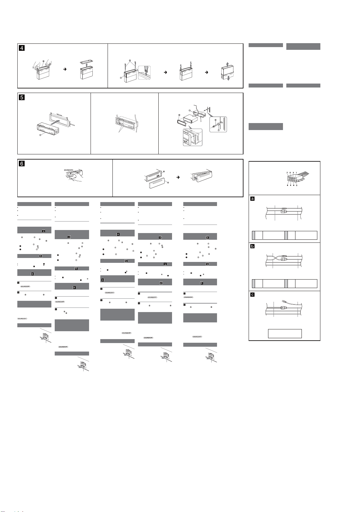
CDX-GT565UP/GT565UV/GT615UV
1
1 2
A
Front panel release button
Taste zum Lösen der Frontplatte
Touche de déverrouillage de la façade
Tasto rilascio pannello anteriore
Toets om het voorpaneel los te maken
Precautions
Choose the installation location carefully so that the
unit will not interfere with normal driving operations.
Avoid installing the unit in areas subject to dust, dirt,
excessive vibration, or high temperature, such as in
direct sunlight or near heater ducts.
Use only the supplied mounting hardware for a safe and
secure installation.
Mounting angle adjustment
Adjust the mounting angle to less than 45°.
Removing the protection
collar and the bracket
Before installing the unit, remove the protection
and the bracket from the unit.
collar
Remove the protection collar .
1
Pinch both edges of the protection collar , then
pull it out.
Remove the bracket .
2
Insert both release keys together between
the unit and the bracket
Pull down the bracket , then pull up the unit
to separate.
Mounting example
Installation in the dashboard
Notes
Bend these claws outward for a tight t, if necessary ( -2).
Make sure that the 4 catches on the protection collar are properly
engaged in the slots of the unit (
-3).
How to detach and attach the
front panel
Before installing the unit, detach the front panel.
-A To detach
Before detaching the front panel, be sure to press and
. Press the front panel release
hold
button, and pull it off towards you.
-B To attach
Engage part of the front panel with part of the unit,
as illustrated, and push the le side into position until it
clicks.
Warning if your car’s ignition
has no ACC position
Be sure to set the Auto Off function. For details, see the
supplied Operating Instructions.
e unit will shut off completely and automatically in the
set time aer the unit is turned off, which prevents
battery drain.
If you do not set the Auto Off function, press and hold
until the display disappears each time
you turn the ignition off.
Fuse replacement
When replacing the fuse, be sure to
use one matching the amperage
rating stated on the original fuse. If
the fuse blows, check the power
connection and replace the fuse. If
the fuse blows again after
replacement, there may be an
internal malfunction. In such a case,
consult your nearest Sony dealer.
until they click.
Fuse (10 A)
Sicherheitshinweise
Wählen Sie den Einbauort sorgfältig so aus, dass das
Gerät beim Fahren nicht hinderlich ist.
Bauen Sie das Gerät so ein, dass es keinen hohen
Temperaturen (keinem direkten Sonnenlicht, keiner
Warmlu von der Heizung), keinem Staub, keinem
Schmutz und keinen starken Vibrationen ausgesetzt ist.
Für eine sichere Befestigung verwenden Sie stets die
mitgelieferten Montageteile.
Hinweis zum Montagewinkel
Das Gerät sollte in einem Winkel von weniger als 45°
montiert werden.
Abnehmen der
Schutzumrandung und der
Halterung
Nehmen Sie vor dem Installieren des Geräts die
und die Halterung vom
Schutzumrandung
Gerät ab.
Entfernen Sie die Schutzumrandung .
1
Fassen Sie die Schutzumrandung mit den
Fingern an den Seitenkanten und ziehen Sie sie
heraus.
Entfernen Sie die Halterung .
2
Führen Sie beide Löseschlüssel zwischen
dem Gerät und der Halterung
mit einem Klicken einrasten.
Ziehen Sie die Halterung nach unten und
das Gerät nach oben, um die beiden zu
trennen.
Montagebeispiel
Installation im Armaturenbrett
Hinweise
Falls erforderlich, biegen Sie diese Klammern für einen sicheren Halt
nach außen (
-2).
Achten Sie darauf, die 4 Verriegelungen an der Schutzumrandung
korrekt in die Aussparungen am Gerät einzusetzen (
Abnehmen und Anbringen
der Frontplatte
Nehmen Sie die Frontplatte vor dem Einbau des
Geräts ab.
-A Abnehmen
Halten Sie vor dem Abnehmen der Frontplatte unbedingt
gedrückt. Drücken Sie die Taste zum
Lösen der Frontplatte und ziehen Sie die Frontplatte auf
sich zu und heraus.
-B Anbringen
Setzen Sie Teil der Frontplatte wie in der Abbildung
des Geräts an und drücken Sie die
dargestellt an Teil
linke Seite der Frontplatte an, bis sie mit einem Klicken
einrastet.
Warnhinweis, wenn die
Zündung Ihres Fahrzeugs nicht
über eine Zubehörposition
(ACC oder I) verfügt
Aktivieren Sie unbedingt die Abschaltautomatik. Näheres
dazu nden Sie in der mitgelieferten
Bedienungsanleitung.
Nach dem Ausschalten wird das Gerät dann nach der
voreingestellten Zeit automatisch vollständig
abgeschaltet, so dass der Autobatterie kein Strom mehr
entzogen wird.
Wenn Sie die Abschaltautomatik nicht aktivieren, müssen
Sie jedes Mal, wenn Sie die Zündung ausschalten, die
gedrückt halten, bis die Anzeige
Taste
ausgeblendet wird.
Austauschen der Sicherung
Wenn Sie eine Sicherung
austauschen, achten Sie darauf, eine
Ersatzsicherung mit dem gleichen
Ampere-Wert wie die
Originalsicherung zu verwenden.
Dieser ist auf der Originalsicherung
angegeben. Wenn die Sicherung
durchbrennt, überprüfen Sie den
Stromanschluss und tauschen die
Sicherung aus. Brennt die neue
Sicherung ebenfalls durch, kann eine
interne Fehlfunktion vorliegen.
Wenden Sie sich in einem solchen
Fall an Ihren Sony-Händler.
ein, bis sie
-3).
Sicherung (10 A)
2
Claws
Klammern
Gries
Morsetti
Klemhaken
B
Précautions
Choisir soigneusement l’emplacement de l’installation
afin que l’appareil ne gêne pas la conduite normale du
véhicule.
Eviter d’installer l’appareil dans un endroit exposé à de
la poussière, de la saleté, des vibrations violentes ou à
des températures élevées, comme en plein soleil ou à
proximité d’un conduit de chauage.
Pour garantir un montage sûr, n’utiliser que le matériel
fourni.
Réglage de l’angle de montage
Ajuster l’inclinaison à un angle inférieur à 45°.
Retrait du tour de protection
et du support
Avant d’installer l’appareil, retirez le tour de
et le support de l’appareil.
protection
Retirez le tour de protection .
1
Saisissez les deux bords du tour de protection ,
puis tirez pour l'extraire.
Retirez le support .
2
Insérez les deux clés de déblocage
simultanément entre l’appareil et le support
jusqu’au déclic indiquant qu’elles sont en place.
Tirez le support vers le bas, puis tirez
l’appareil vers le haut pour les séparer.
Exemple de montage
Installation dans le tableau de bord
Remarques
Pliez ces gries vers l’extérieur pour assurer une prise correcte si
nécessaire (
-2).
Assurez-vous que les 4 loquets du tour de protection sont
correctement insérés dans les fentes de l’appareil (
Retrait et xation de la façade
Avant d’installer l’appareil, retirez la façade.
-A Pour la retirer
Avant de détacher la façade, n’oubliez pas d’appuyer sur la
touche
Appuyez sur la touche de déverrouillage de la façade et
détachez-la en la tirant vers vous.
-B Pour la xer
Fixez la partie de la façade sur la partie de
l’appareil, comme indiqué sur l’illustration, puis appuyez
sur le côté gauche jusqu’au déclic.
Avertissement au cas où le
contact de votre voiture ne
dispose pas d’une position
ACC
Veillez à régler la fonction de mise hors tension
automatique. Pour obtenir davantage d’informations,
reportez-vous au mode d’emploi fourni.
L’appareil s’éteint complètement et automatiquement
après le laps de temps choisi une fois l’appareil mis hors
tension afin d’éviter que la batterie ne se décharge.
Si vous ne réglez pas la fonction de mise hors tension
automatique, appuyez sur la touche
maintenez-la enfoncée jusqu’à ce que l’achage
disparaisse à chaque fois que vous coupez le contact.
Remplacement du fusible
Lorsque vous remplacez le fusible,
veillez à utiliser un fusible dont
l’intensité, en ampères, correspond à
la valeur indiquée sur le fusible
usagé. Si le fusible saute, vériez le
branchement de l’alimentation et
remplacez-le. Si le nouveau fusible
saute également, il est possible que
l’appareil soit défectueux. Dans ce
cas, consultez votre revendeur Sony
le plus proche.
-3).
et de la maintenir enfoncée.
Fusible (10 A)
Face the hook inwards.
Der Haken muss nach innen
weisen.
Tournez le crochet vers
l’intérieur.
Con il gancetto rivolto verso
l’interno.
Het haakje moet naar binnen
wijzen.
Precauzioni
Scegliere con attenzione la posizione per l’installazione
in modo che l’apparecchio non interferisca con le
operazioni di guida del conducente.
Evitare di installare l’apparecchio dove sia soggetto ad
alte temperature, come alla luce solare diretta o al getto
di aria calda dell’impianto di riscaldamento, o dove
possa essere soggetto a polvere, sporco e vibrazioni
eccessive.
Usare solo il materiale di montaggio in dotazione per
un’installazione stabile e sicura.
Regolazione dell’angolo di montaggio
Regolare l’angolo di montaggio in modo che sia inferiore
a 45°.
Rimozione della staa e della
cornice protettiva
Prima di installare l’apparecchio, rimuovere la
e la staa dall’apparecchio.
cornice protettiva
Rimuovere la cornice protettiva .
1
Afferrare la cornice di protezione dai bordi
laterali, quindi estrarla.
Rimuovere la staa .
2
Inserire contemporaneamente entrambe le
chiavette di rilascio
staffa
no a che non scattano in posizione.
Estrarre la staa quindi sollevare
l’apparecchio per rimuoverlo.
Esempio di montaggio
Installazione nel cruscotto
Note
Piegare verso l’esterno questi morsetti per un’installazione più sicura,
-2).
se necessario (
Assicurarsi che i 4 fermi sulla cornice protettiva siano
correttamente inseriti negli alloggiamenti dell’apparecchio (
Come rimuovere e reinserire il
pannello anteriore
Prima di installare l’apparecchio rimuovere il
pannello anteriore.
-A Per rimuoverlo
Prima di staccare il pannello anteriore, assicurarsi di
tenere premuto
pannello anteriore, quindi tirare il pannello verso di sé.
-B Per reinserirlo
Applicare la parte del pannello anteriore alla parte
dell’apparecchio come mostrato nell’illustrazione e
premere il lato sinistro no a sentire uno scatto.
Avvertenza relativa all’installazione
su un’auto sprovvista della
posizione ACC (accessoria) sul
blocchetto di accensione
Accertarsi di impostare la funzione di spegnimento
automatico. Per ulteriori informazioni, fare riferimento
alle istruzioni per l’uso in dotazione.
L’apparecchio si spegne completamente e
automaticamente all’ora impostata dopo che è stato
disattivato, onde evitare che la batteria si scarichi.
et
Se la funzione di spegnimento automatico non è stata
impostata, ogni volta che il motore viene spento tenere
nché il display non viene
premuto
disattivato.
Sostituzione del fusibile
Per la sostituzione del fusibile,
assicurarsi di utilizzare un fusibile
dello stesso amperaggio di quello
indicato sull’originale. Se il fusibile si
brucia, controllare i collegamenti
dell’alimentazione e sostituire il
fusibile. Se dopo la sostituzione il
fusibile si brucia di nuovo, è
possibile che si tratti di un problema
interno. In tal caso, rivolgersi al più
vicino rivenditore Sony.
3
tra l’apparecchio e la
. Premere il tasto rilascio
Fusibile (10 A)
Dashboard
Armaturenbrett
Tableau de bord
Cruscotto
Dashboard
Maximale montagehoek
Installeer het apparaat nooit in een hoek van meer dan
45° met het horizontale vlak.
Voordat u het apparaat gaat installeren, moet u de
beschermende rand
verwijderen van het apparaat.
1
2
Montage in het dashboard
Opmerkingen
-3).
Verwijder, alvorens met het installeren te
beginnen, het afneembare voorpaneel.
Voordat u het voorpaneel verwijdert, moet u
om het voorpaneel los te maken en trek het voorpaneel
naar u toe.
Breng deel van het voorpaneel aan op deel van het
apparaat zoals afgebeeld en druk op de linkerzijde tot
deze vastklikt.
Zorg ervoor dat u de functie voor automatisch
uitschakelen instelt. Raadpleeg de bijgeleverde
gebruiksaanwijzing voor meer informatie.
Het apparaat wordt na de ingestelde tijd automatisch
volledig uitgeschakeld nadat het apparaat is
uitgeschakeld. Zo wordt voorkomen dat de accu
leegloopt.
Als u de functie voor automatisch uitschakelen niet
instelt, moet u
het display verdwijnt telkens wanneer u het contact
uitschakelt.
Vervang een zekering altijd door
een exemplaar van een zelfde
ampèrage als op de oorspronkelijke
zekering wordt vermeld. Als de
zekering doorbrandt, moet u de
voedingsaansluiting controleren en
de zekering vervangen. Brandt de
zekering vervolgens nogmaals door,
dan kan er sprake zijn van een
defect in het apparaat. Raadpleeg in
dat geval de Sony-dealer bij u in de
buurt.
Fire wall
Motorraumtrennwand
Paroi ignifuge
Parete tagliaamma
Brandschot
Voorzorgsmaatregelen
Kies de installatieplaats zorgvuldig zodat het apparaat
de bestuurder niet hindert tijdens het rijden.
Installeer het apparaat niet op plaatsen waar het
blootgesteld wordt aan hoge temperaturen, bv. in
direct zonlicht of bij de warme luchtstroom van de
autoverwarming, aan sterke trillingen, of waar het in
contact komt met veel stof of vuil.
Gebruik voor het veilig en stevig monteren van het
apparaat uitsluitend de bijgeleverde montageonderdelen.
De beschermende rand en de
beugel verwijderen
en de beugel
Verwijder de beschermende rand .
Druk beide zijden van de beschermende rand
in en trek de rand naar u toe.
Verwijder de beugel .
Plaats de ontgrendelingssleutels tussen het
apparaat en de beugel
tot deze vastklikken.
Trek de beugel omlaag en trek het apparaat
omhoog om deze van elkaar te scheiden.
Montagevoorbeeld
Indien nodig kunt u deze klemhaken ombuigen voor een stevigere
bevestiging (
-2).
De 4 grepen op de beschermende rand moeten goed in de sleuven
-3).
van het apparaat zijn geplaatst (
Het voorpaneel verwijderen
en bevestigen
-A Verwijderen
ingedrukt houden. Druk op de toets
-B Bevestigen
Waarschuwing als het
contactslot van de auto geen
ACC-positie heeft
ingedrukt houden tot
Zekering vervangen
Zekering (10 A)
Power connection diagram
Auxiliary power connector may vary depending on the
car. Check your car’s auxiliary power connector diagram
to make sure the connections match correctly. ere are
three basic types (illustrated below). You may need to
switch the positions of the red and yellow leads in the car
stereo’s power supply lead.
Aer matching the connections and switched power
supply leads correctly, connect the unit to the car’s power
supply. If you have any questions and problems
connecting your unit that are not covered in this manual,
please consult the car dealer.
Stromanschlussdiagramm
Der Hilfsstromanschluss kann je nach Fahrzeugtyp
unterschiedlich sein. Sehen Sie im Hilfsstromanschlussdiagramm für Ihr Fahrzeug nach, wie die
Verbindung ordnungsgemäß vorgenommen werden
muss. Es gibt, wie unten abgebildet, drei grundlegende
Typen. Sie müssen möglicherweise die rote und gelbe
Leitung des Stromversorgungskabels der
Autostereoanlage vertauschen.
Stellen Sie die Anschlüsse her, schließen Sie die
geschalteten Stromversorgungsleitungen richtig an und
verbinden Sie dann das Gerät mit der Stromversorgung
Ihres Fahrzeugs. Wenn beim Anschließen des Geräts
Fragen oder Probleme aureten, die in dieser Anleitung
nicht erläutert werden, wenden Sie sich bitte an den
Autohändler.
Schéma de raccordement
d’alimentation
Le connecteur d’alimentation auxiliaire peut varier
suivant le type de voiture. Vériez le schéma du
connecteur d’alimentation auxiliaire de votre voiture pour
vous assurer que les connexions correspondent. Il en
existe trois types de base (illustrés ci-dessous). Il se peut
que vous deviez commuter la position des ls rouge et
jaune du câble d’alimentation de l’autoradio.
Après avoir établi les connexions et commuté
correctement les câbles d’alimentation, raccordez
l’appareil à l’alimentation de la voiture. Si vous avez des
questions ou des dicultés à propos de cet appareil qui
ne sont pas abordées dans le présent mode d’emploi,
consultez votre concessionnaire automobile.
Auxiliary power connector
Hilfsstromanschluss
Connecteur d’alimentation auxiliaire
Connettore di alimentazione ausiliaria
Hulpvoedingsaansluiting
Red
Rot
Rouge
Rosso
Rood
Yellow
Gelb
Jaune
Giallo
Geel
Yellow
continuous power supply
Gelb
permanente Stromversorgung
4
Jaune
alimentation continue
Giallo
alimentazione continua
Geel
continue voeding
Red
Rot
Rouge
Rosso
Rood
Yellow
Gelb
Jaune
Giallo
Geel
Yellow
switched power supply
Gelb
geschaltete Stromversorgung
Jaune
4
alimentation commutée
Giallo
alimentazione commutata
Geel
geschakelde voeding
Red
Rot
Rouge
Rosso
Rood
Yell o w
Gelb
Jaune
Giallo
Geel
the car without ACC position
Fahrzeug ohne Zubehörposition (ACC oder I)
Véhicule sans position ACC
Auto priva della posizione ACC
Auto zonder ACC-positie
Diagramma dei collegamenti
di alimentazione
Il connettore di alimentazione ausiliaria può variare a
seconda della macchina. Controllare il diagramma del
connettore di alimentazione ausiliaria della macchina per
essere sicuri che i collegamenti corrispondano
correttamente. Vi sono tre tipi di base (illustrazione
sotto). Potrà essere necessario cambiare le posizioni dei
li rosso e giallo nel cavo di alimentazione dello stereo
della macchina.
Dopo aver fatto corrispondere i collegamenti e aver
commutato i cavi di alimentazione, collegare
l’apparecchio all’alimentazione della macchina. Se si
hanno domande o se sorgono problemi che non sono
stati trattati nel manuale nel collegare l’apparecchio,
contattare l’autoconcessionario.
Voedingsaansluitschema
De hulpvoedingsaansluiting kan verschillen afhankelijk
van de auto. Controleer het hulpvoedingsaansluitschema
dat bij dit apparaat wordt geleverd om te zien of de
aansluitingen kloppen. Er zijn drie basistypes (zie
afbeelding hieronder). Het is mogelijk dat u de posities
van de rode en gele kabels in de voedingskabel van het
autoaudiosysteem moet omwisselen.
Als de aansluitingen en geschakelde voedingskabels
kloppen, sluit u het apparaat aan op de voeding van de
auto. Indien u nog vragen of problemen hebt in verband
met het aansluiten van het apparaat die niet in deze
handleiding worden behandeld, raadpleeg dan de
autodealer.
Red
Rot
Rouge
Rosso
Rood
Yellow
Gelb
Jaune
Giallo
Geel
Red
switched power supply
Rot
geschaltete Stromversorgung
7
Rouge
alimentation commutée
Rosso
alimentazione commutata
Rood
geschakelde voeding
Red
Rot
Rouge
Rosso
Rood
Yellow
Gelb
Jaune
Giallo
Geel
Red
continuous power supply
Rot
permanente Stromversorgung
7
Rouge
alimentation continue
Rosso
alimentazione continua
Rood
continue voeding
Red
Rot
Rouge
Rosso
Rood
Yellow
Gelb
Jaune
Giallo
Geel
10
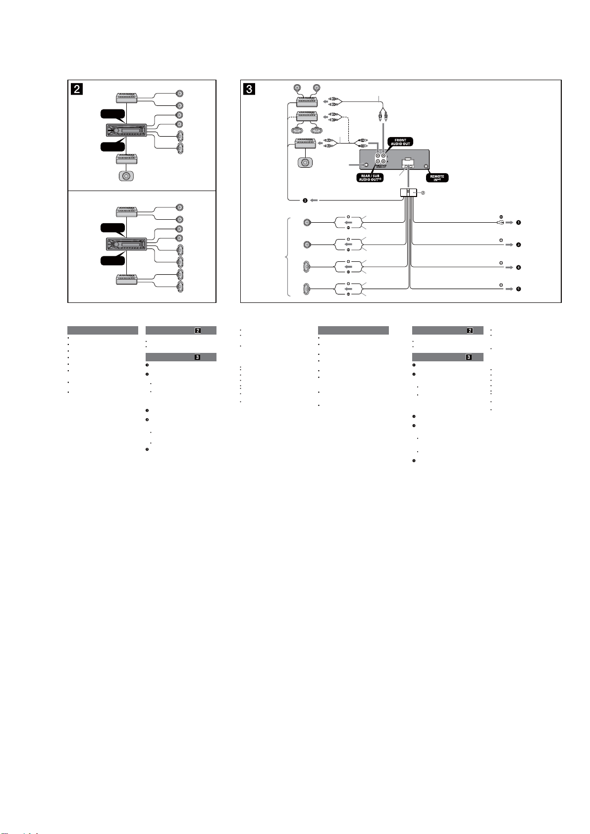
(CDX-GT615UV)
CDX-GT565UP/GT565UV/GT615UV
A
FRONT
AUDIO OUT
REAR / SUB
AUDIO OUT
B
FRONT
AUDIO OUT
REAR / SUB
AUDIO OUT
Cautions
is unit is designed for negative ground (earth) 12 V
DC operation only.
Do not get the leads under a screw, or caught in moving
parts (e.g. seat railing).
Before making connections, turn the car ignition off to
avoid short circuits.
Connect the yellow and red power input leads only
after all other leads have been connected.
Run all ground (earth) leads to a common ground
(earth) point.
Be sure to insulate any loose unconnected leads with
electrical tape for safety.
Notes on the power supply lead (yellow)
When connecting this unit in combination with other
stereo components, the connected car circuit’s rating
must be higher than the sum of each component’s fuse.
When no car circuits are rated high enough, connect
the unit directly to the battery.
Connection example
Notes
Be sure to connect the ground (earth) lead before connecting the
amplier.
The alarm will only sound if the built-in amplier is used.
Connection diagram
To a metal surface of the car
First connect the black ground (earth) lead, then connect the
yellow, and red power supply leads.
To the power antenna (aerial) control lead or
power supply lead of antenna (aerial) booster
Notes
It is not necessary to connect this lead if there is no power
antenna (aerial) or antenna (aerial) booster, or with a
manually-operated telescopic antenna (aerial).
When your car has a built-in FM/AM antenna (aerial) in the rear/
side glass, see “Notes on the control and power supply leads.”
To AMP REMOTE IN of an optional power
amplier
This connection is only for ampliers. Connecting any other system
may damage the unit.
To a car’s illumination signal
Be sure to connect the black ground (earth) lead to a metal surface
of the car rst.
To the +12 V power terminal which is energized
in the accessory position of the ignition key
switch
Notes
If there is no accessory position, connect to the +12 V power
(battery) terminal which is energized at all times.
Be sure to connect the black ground (earth) lead to a metal
surface of the car rst.
When your car has a built-in FM/AM antenna (aerial) in the rear/
side glass, see “Notes on the control and power supply leads.”
To the +12 V power terminal which is energized
at all times
Be sure to connect the black ground (earth) lead to a metal surface
of the car rst.
Left
Izquierdo
Right
Derecho
1
*
Left
Izquierdo
Right
Derecho
Notes on the control and power supply leads
REM OUT lead (blue/white striped) supplies +12 V DC when you turn
on the unit.
When your car has built-in FM/AM antenna (aerial) in the rear/side
glass, connect REM OUT lead (blue/white striped) or the accessory
power supply lead (red) to the power terminal of the existing antenna
(aerial) booster. For details, consult your dealer.
A power antenna (aerial) without a relay box cannot be used with this
unit.
Memory hold connection
When the yellow power input lead is connected, power will always be
supplied to the memory circuit even when the ignition switch is turned
o.
Notes on speaker connection
Before connecting the speakers, turn the unit o.
Use speakers with an impedance of 4 to 8 ohms, and with adequate
power handling capacities to avoid its damage.
Do not connect the speaker terminals to the car chassis, or connect the
terminals of the right speakers with those of the left speaker.
Do not connect the ground (earth) lead of this unit to the negative (–)
terminal of the speaker.
Do not attempt to connect the speakers in parallel.
Connect only passive speakers. Connecting active speakers (with
built-in ampliers) to the speaker terminals may damage the unit.
To avoid a malfunction, do not use the built-in speaker leads installed
in your car if the unit shares a common negative (–) lead for the right
and left speakers.
Do not connect the unit’s speaker leads to each other.
Note on connection
If speaker and amplier are not connected correctly, “FAILURE” appears
in the display. In this case, make sure the speaker and amplier are
connected correctly.
2
*
from car antenna (aerial)
desde la antena del
automóvil
REM OUT
Max. supply current 0.4 A
Corriente máx. de alimentación de 0,4 A
Precauciones
Esta unidad ha sido diseñada para alimentarse sólo con
cc de 12 V de masa negativa.
No coloque los cables debajo de ningún tornillo, ni los
aprisione con partes móviles (p. ej. los rieles del
asiento).
Antes de realizar las conexiones, apague el automóvil
para evitar cortocircuitos.
Conecte los cables de fuente de alimentación amarillo
y rojo solamente después de haber conectado los
demás.
Conecte todos los cables de conexión a masa a un
punto común.
Por razones de seguridad, asegúrese de aislar con cinta
aislante los cables sueltos que no estén conectados.
Notas sobre el cable de fuente de alimentación
(amarillo)
Cuando conecte esta unidad en combinación con otros
componentes estéreo, la capacidad nominal del circuito
conectado del automóvil debe ser superior a la suma del
fusible de cada componente.
Si no hay circuitos del automóvil con capacidad
nominal suficientemente alta, conecte la unidad
directamente a la batería.
Blue/white striped
Con rayas azules y blancas
White
Blanco
White/black striped
Con rayas blancas y negras
Gray
Gris
Gray/black striped
Con rayas grises y negras
Green
Verde
Green/black striped
Con rayas verdes y negras
Purple
Morado
Purple/black striped
Con rayas moradas y negras
2
*
Fuse (10 A)
Fusible (10 A)
1
*
Speaker impedance: 4 – 8 ohms × 4
2
*
RCA pin cord (not supplied)
3
*
AUDIO OUT can be switched SUB or REAR.
For details, see the supplied Operating
Instructions.
4
*
Separate adaptor may be required.
Black
Negro
Orange/white striped
Con rayas naranjas y blancas
Red
Rojo
Yellow
Amarillo
Ejemplo de conexiones
Notas
Asegúrese de conectar primero el cable de conexión a masa antes de
realizar la conexión del amplicador.
La alarma sonará únicamente si se utiliza el amplicador incorporado.
Diagrama de conexión
A una supercie metálica del automóvil
Conecte primero el cable de conexión a masa negro, y después los
cables amarillo y rojo de fuente de alimentación.
Al cable de control de la antena motorizada o al
cable de fuente de alimentación del
amplicador de señal de la antena
Notas
Si no se dispone de antena motorizada ni de amplicador de
señal de la antena, o se utiliza una antena telescópica accionada
manualmente, no será necesario conectar este cable.
Si el automóvil tiene una antena de FM/AM incorporada en el
cristal trasero o lateral, consulte “Notas sobre los cables de
control y de fuente de alimentación”.
A AMP REMOTE IN de un amplicador de
potencia opcional
Esta conexión es sólo para amplicadores. La conexión de cualquier
otro sistema puede dañar la unidad.
A una señal de iluminación del automóvil
Asegúrese de conectar primero el cable de conexión a masa negro a
una supercie metálica del automóvil.
Al terminal de alimentación de +12 V que recibe
energía en la posición de accesorio del
interruptor de encendido
Notas
Si no hay posición de accesorio, conéctelo al terminal de
alimentación (batería) de +12 V que recibe energía sin
interrupción.
Asegúrese de conectar primero el cable de conexión a masa
negro a una supercie metálica del automóvil.
Si el automóvil tiene una antena de FM/AM incorporada en el
cristal trasero o lateral, consulte “Notas sobre los cables de
control y de fuente de alimentación”.
Al terminal de alimentación de +12 V que recibe
energía sin interrupción
Asegúrese de conectar primero el cable de conexión a masa negro a
una supercie metálica del automóvil.
1
Impedancia de los altavoces:
*
de 4 a 8 Ω × 4
2
*
Cable con terminales RCA (no suministrado)
3
*
AUDIO OUT (salida de audio) puede
cambiarse a SUB o REAR. Para obtener
información, consulte el manual de
instrucciones suministrado.
4
*
Puede requerirse un adaptador
independiente.
ILLUMINATION
ACC
BATTERY
Notas sobre los cables de control y de fuente de alimentación
El cable REM OUT (rayado azul y blanco) suministra cc +12 V al
encender la unidad.
Si el automóvil dispone de una antena de FM/AM incorporada en el
cristal trasero o lateral, conecte el cable REM OUT (rayado azul y
blanco) o el cable de fuente de alimentación auxiliar (rojo) al terminal
de alimentación del amplicador de señal de la antena existente. Para
obtener más detalles, consulte a su distribuidor.
Con esta unidad no es posible utilizar una antena motorizada sin caja
de relé.
Conexión para protección de la memoria
Si conecta el cable de fuente de alimentación amarillo, el circuito de la
memoria recibirá siempre alimentación, aunque apague el interruptor
de encendido.
Notas sobre la conexión de los altavoces
Antes de conectar los altavoces, desconecte la alimentación de la
unidad.
Utilice altavoces con una impedancia de 4 a 8 Ω con la capacidad de
potencia adecuada para evitar que se dañen.
No conecte los terminales de altavoz al chasis del automóvil, ni
conecte los terminales del altavoz derecho con los del izquierdo.
No conecte el cable de conexión a masa de esta unidad al terminal
negativo (–) del altavoz.
No intente conectar los altavoces en paralelo.
Conecte solamente altavoces pasivos. Si conecta altavoces activos
(con amplicadores incorporados) a los terminales de altavoz, puede
dañar la unidad.
Para evitar fallas de funcionamiento, no utilice los cables de altavoz
incorporados instalados en el automóvil si la unidad comparte un
cable negativo común (–) para los altavoces derecho e izquierdo.
No conecte los cables de altavoz de la unidad entre sí.
Nota sobre la conexión
Si el altavoz y el amplicador no están conectados correctamente,
aparecerá “FAILURE” en la pantalla. Si es así, compruebe la conexión de
ambos dispositivos.
11
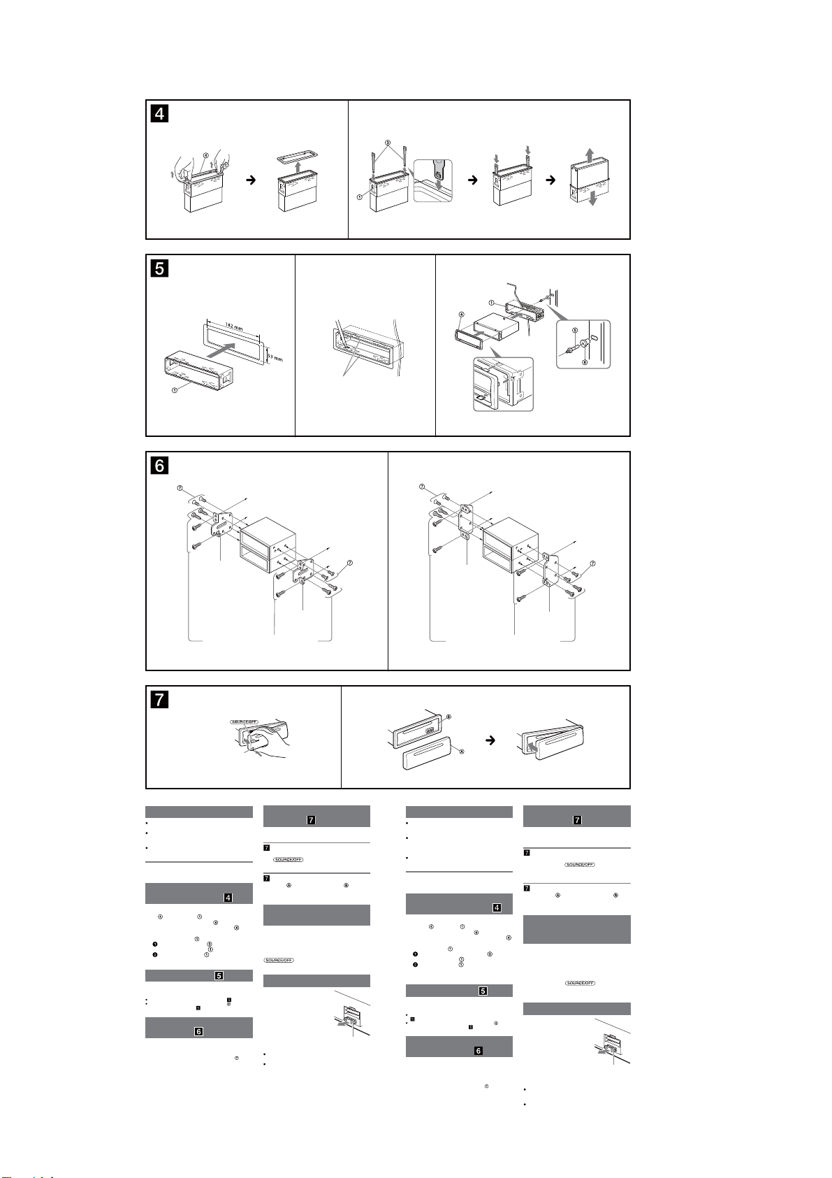
CDX-GT565UP/GT565UV/GT615UV
12
Face the hook inwards.
El gancho debe
encontrarse en la parte
interior.
1
23
Claws
Uñas
A TOYOTA B NISSAN
size
5 × max. 8 mm
7
/32 × max. 5/16 in)
(
Tamaño
5 × 8 mm máx.
Bracket
Soporte
Existing parts supplied with your car
Piezas existentes suministradas con su automóvil
to dashboard/center console
al tablero o consola central
Bracket
Soporte
size
5 × max. 8 mm
7
/32 × max. 5/16 in)
(
Tamaño
5 × 8 mm máx.
size
5 × max. 8 mm
7
/32 × max. 5/16 in)
(
Tamaño
5 × 8 mm máx.
Dashboard
Tablero
Bracket
Soporte
Existing parts supplied with your car
Piezas existentes suministradas con su automóvil
Fire wall
Cortafuegos
to dashboard/center console
al tablero o consola central
Bracket
Soporte
size
5 × max. 8 mm
7
(
/32 × max. 5/16 in)
Tamaño
5 × 8 mm máx.
AB
Front panel release button
Botón de liberación del panel frontal
Precautions
Choose the installation location carefully so that the
unit will not interfere with normal driving operations.
Avoid installing the unit in areas subject to dust, dirt,
excessive vibration, or high temperatures, such as in
direct sunlight or near heater ducts.
Use only the supplied mounting hardware for a safe and
secure installation.
Mounting angle adjustment
Adjust the mounting angle to less than 45°.
Removing the protection
collar and the bracket
Before installing the unit, remove the protection
and the bracket from the unit.
collar
Remove the protection collar .
1
Pinch both edges of the protection collar , then
pull it out.
Remove the bracket .
2
Insert both release keys together between
the unit and the bracket
Pull down the bracket , then pull up the unit
to separate.
until they click.
Mounting example
Installation in the dashboard
Notes
Bend these claws outward for a tight t, if necessary ( -2).
Make sure that the 4 catches on the protection collar are properly
engaged in the slots of the unit (
Mounting the unit in a
Japanese car
You may not be able to install this unit in some makes of
Japanese cars. In such a case, consult your Sony dealer.
Note
To prevent malfunction, install only with the supplied screws
-3).
How to detach and attach the
front panel
Before installing the unit, detach the front panel.
-A To detach
Before detaching the front panel, be sure to press and
. Press the front panel release
hold
button, and pull it off towards you.
-B To attach
Engage part of the front panel with part of the unit,
as illustrated, and push the le side into position until it
clicks.
Warning if your car’s ignition
has no ACC position
Be sure to set the Auto Off function. For details, see the
supplied Operating Instructions.
e unit will shut off completely and automatically in the
set time aer the unit is turned off, which prevents
battery drain.
If you do not set the Auto Off function, press and hold
until the display disappears each time
you turn the ignition off.
Fuse replacement
When replacing the fuse, be sure to
use one matching the amperage
rating stated on the original fuse. If
the fuse blows, check the power
connection and replace the fuse. If
the fuse blows again after
replacement, there may be an
internal malfunction. In such a case,
consult your nearest Sony dealer.
Notes on the tuning step
For how to set the tuning step, see the supplied
.
Operating Instructions.
If replacing the car battery or changing the connections,
the tuning step setting will be erased.
Fuse (10 A)
Precauciones
Elija cuidadosamente el lugar de montaje de forma que
la unidad no interera con las funciones normales de
conducción.
Evite instalar la unidad donde pueda quedar estén a
polvo, suciedad, vibraciones excesivas o altas
temperaturas, por ejemplo, a la luz solar directa o cerca
de conductos de calefacción.
Para realizar una instalación segura y rme, utilice
solamente elementos de instalación suministrados.
Ajuste del ángulo de montaje
Ajuste el ángulo de montaje a menos de 45°.
Extracción del marco de
protección y del soporte
Antes de instalar la unidad, retire el marco de
y el soporte de la misma.
protección
Retire el marco de protección .
1
Apriete ambos bordes del marco de protección
y, a continuación, tire de él hacia fuera.
Retire el soporte .
2
Inserte ambas llaves de liberación entre la
unidad y el soporte
Presione el soporte y, a continuación,
levante la unidad para separar ambos
elementos.
Ejemplo de montaje
Instalación en el tablero
Notas
Si es necesario, doble las uñas hacia fuera para que encaje rmemente
(
-2).
Compruebe que los 4 enganches del marco de protección estén
bien jados en las ranuras de la unidad (
Montaje de la unidad en un
automóvil japonés
Es posible que no pueda instalar esta unidad en algunos
automóviles japoneses. En tal caso, consulte a su
distribuidor Sony.
Nota
Para evitar que se produzcan fallas de funcionamiento, realice la
instalación solamente con los tornillos suministrados
hasta que encajen.
-3).
.
Forma de extraer e instalar el
panel frontal
Antes de instalar la unidad, extraiga el panel
frontal.
-A Para extraerlo
Antes de desconectar el panel frontal, asegúrese de
mantener presionado
de liberación del panel frontal y extraiga el panel frontal
hacia usted.
-B Para instalarlo
Coloque la parte del panel frontal en la parte de la
unidad, como se muestra en la ilustración, y después
presione la parte izquierda hasta que encaje.
Advertencia: si el encendido
del automóvil no dispone de
una posición ACC
Asegúrese de ajustar la función de desconexión
automática. Para obtener más información, consulte el
manual de instrucciones suministrado.
La unidad se apagará completa y automáticamente en el
tiempo establecido después de que se desconecte la
unidad, lo que evita que se desgaste la batería.
Si no ha ajustado la función de desconexión automática,
mantenga presionado
apague el interruptor de encendido, hasta que la pantalla
desaparezca.
Sustitución del fusible
Al sustituir el fusible, asegúrese de
utilizar uno cuyo amperaje coincida
con el especicado en el original. Si
el fusible se funde, verique la
conexión de alimentación y
sustitúyalo. Si el fusible vuelve a
fundirse después de sustituirlo, es
posible que exista alguna falla de
funcionamiento interno. En tal caso,
consulte con el distribuidor Sony
más cercano.
Notas acerca de la sintonización
Para obtener información sobre cómo ajustar la
sintonización, consulte el manual de instrucciones
suministrado.
Si se reemplaza la batería del automóvil o se cambian
las conexiones, la conguración de la sintonización se
borrará.
. Presione el botón
cada vez que
Fusible (10 A)
12
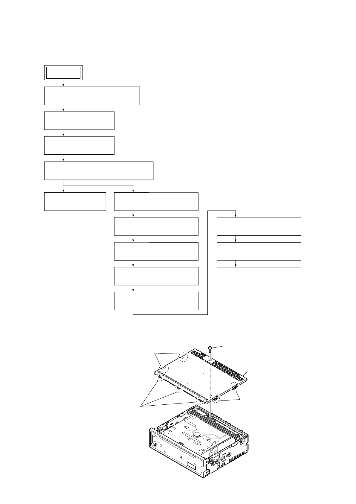
DISASSEMBLY
• This set can be disassembled in the order shown below.
3-1. DISASSEMBLY FLOW
SET
CDX-GT565UP/GT565UV/GT615UV
SECTION 3
FRONT PANEL SECTION
Note:
Illustration of disassembly is omitted.
3-2. COVER
(Page 13)
3-3. SUB PANEL BLOCK
(Page 14)
3-4. CD MECHANISM DECK (MG-101CA-188)
(Page 14)
3-5. MAIN BOARD
(Page 15)
3-6. SERVO BOARD
(Page 16)
3-7. CHASSIS (T) SUB ASSY
(Page 17)
3-8. ROLLER ARM ASSY
(Page 17)
3-11. SLED MOTOR ASSY
(Page 19)
3-12. OPTICAL PICK-UP SECTION
(Page 19)
3-9. CHASSIS (OP) ASSY
(Page 18)
3-10. CHUCKING ARM SUB ASSY
(Page 18)
Note: Follow the disassembly procedure in the numerical order given.
3-2. COVER
2 two bosses
3 three claws
3-13. OPTICAL PICK-UP
(Page 19)
1 screw
(PTT2.6 u 6)
4 cover
2 two bosses
13

CDX-GT565UP/GT565UV/GT615UV
3-3. SUB PANEL BLOCK
2 two claws
3
2 two claws
1 two
screws
(PTT2.6
u
6)
4 sub panel block
3-4. CD MECHANISM DECK (MG-101CA-188)
6 CD mechanism deck
(MG-101CA-188)
5 bracket (CD)
4 two
screws
(PTT2.6
u
4)
14
1
screw
(PTT2.6
3 CN700
u
6)
2
1
screw
(PTT2.6
u
6)
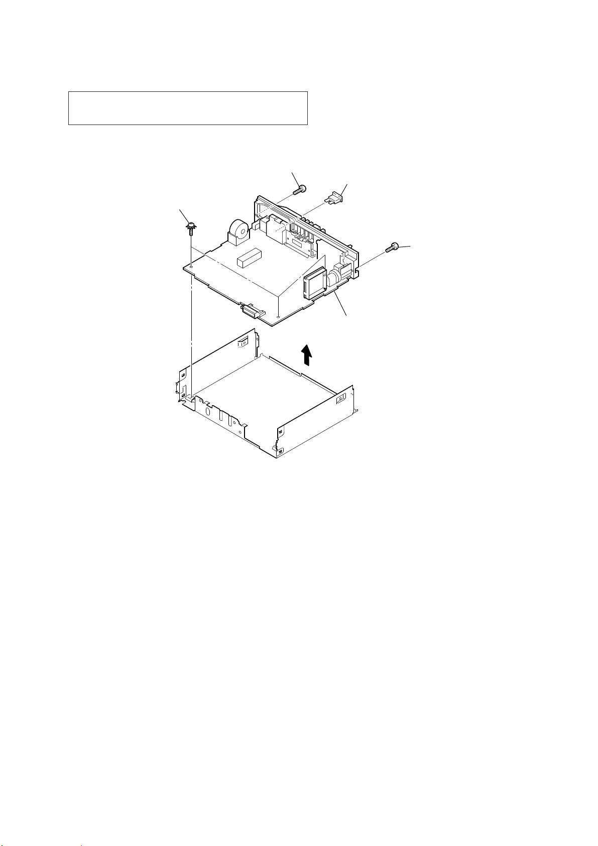
3-5. MAIN BOARD
Note: When the complete MAIN board is replaced, the destination
setting is necessary. Refer to “NOTE THE MAIN BOARD OR
SYSTEM CONTROLLER (IC501) REPLACING” on page 4.
3 screw
(PTT2.6 u 8)
2 three ground point screws
(PTT2.6 u 6)
CDX-GT565UP/GT565UV/GT615UV
1 fuse (blade type) (auto fuse) (10A/32V)
(FU301)
3 screw
(PTT2.6 u 8)
4
5 MAIN board
15
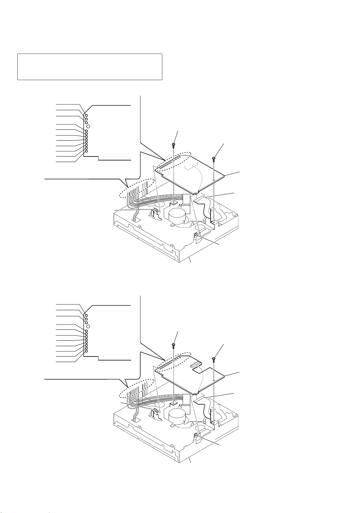
CDX-GT565UP/GT565UV/GT615UV
Ver. 1.2
3-6. SERVO BOARD
Note: In this unit, the complete SERVO board has been changed in the
midway of production. When replacing the complete SERVO
board, refer to “ABOUT THE MG-101CA-188 OF FORMER
AND NEW” on page 6.
• Former type
WHT
RED
BLK
WHT
RED
BLK
RED
ORG
BLU
YEL
GRY
SERVO board
2 toothed lock screw
(M1.7 u 2.5)
2 toothed lock screw
(M1.7 u 2.5)
1 Remove the eleven solders.
• New type
WHT
RED
BLK
WHT
RED
BLK
RED
ORG
BLU
YEL
GRY
6 SERVO board
5 optical pick-up (16 core)
(CN101)
4 claw
3 claw
CD mechanism deck
– CD mechanism deck bottom side view –
2 toothed lock screw
(M1.7 u 2.5)
2 toothed lock screw
(M1.7 u 2.5)
SERVO board
16
1 Remove the eleven solders.
4 claw
6 SERVO board
5 optical pick-up (16 core)
(CN101)
3 claw
CD mechanism deck
– CD mechanism deck bottom side view –
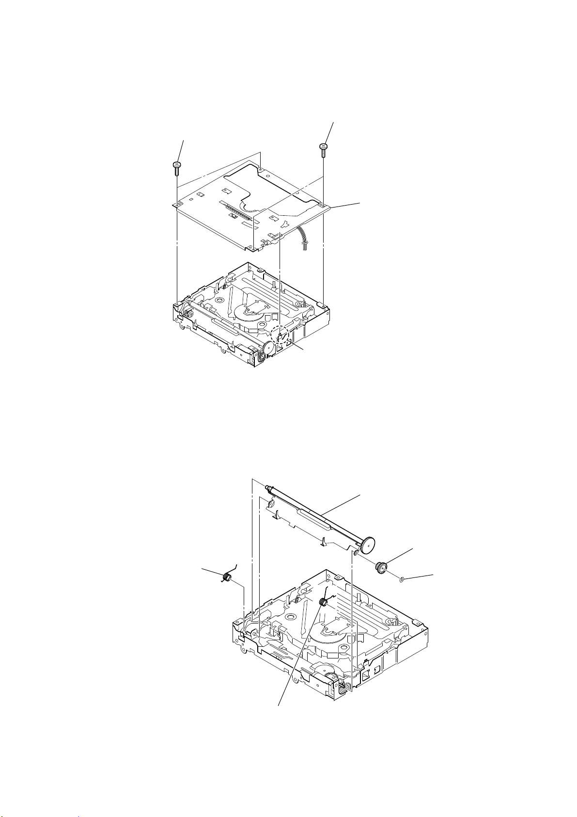
3-7. CHASSIS (T) SUB ASSY
1 two screws
(M1.7 u 2.5)
CDX-GT565UP/GT565UV/GT615UV
1 two screws
(M1.7 u 2.5)
3 chassis (T) sub assy
3-8. ROLLER ARM ASSY
1 spring (RAL)
2 claw
5 roller arm assy
4 gear (HRA)
3 washer
2 spring (RAR)
17
 Loading...