

Sony CDXGT-48-UM, CDXGT-480-U, CDXGT-480-US, CDXGT-484-US Service manual
CDX-GT48UM/GT480U/
GT480US/GT484US
SERVICE MANUAL
Ver. 1.0 2008.11
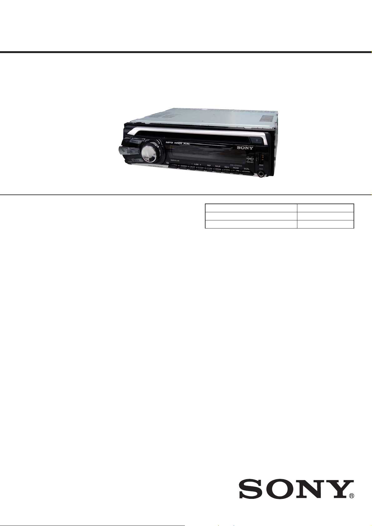
Photo: CDX-GT480US
• The tuner and CD sections have no adjustments.
SPECIFICATIONS
E Model
CDX-GT480U/GT480US
Indian Model
CDX-GT48UM/GT484US
Model Name Using Similar Mechanism NEW
CD Drive Mechanism Type MG-101Y-188//C
Optical Pick-up Name DAX-25A
CD player section
Signal-to-noise ratio: 120 dB
Frequency response: 10 – 20,000 Hz
Wow and fl utter: Below measurable limit
Tuner section
FM
Tuning range:
87.5 – 108.0 MHz (at 50 kHz step)
87.5 – 107.9 MHz (at 200 kHz step)
FM tuning interval: 50 kHz/200 kHz switchable
Antenna (aerial) terminal:
External antenna (aerial) connector
Intermediate frequency: 150 kHz
Usable sensitivity: 10 dBf
Selectivity: 75 dB at 400 kHz
Signal-to-noise ratio: 70 dB (mono)
Separation: 40 dB at 1 kHz
Frequency response: 20 – 15,000 Hz
AM
Tuning range:
531 – 1,602 kHz (at 9 kHz step)
530 – 1,710 kHz (at 10 kHz step)
AM tuning interval: 9 kHz/10 kHz switchable
Antenna (aerial) terminal:
External antenna (aerial) connector
Intermediate frequency: 25 kHz
Sensitivity: 26 μV
USB Player section
Interface: USB (Full-speed)
Maximum current: 500 mA
Power amplifi er section
Outputs: Speaker outputs (sure seal connectors)
Speaker impedance: 4 – 8 ohms
Maximum power output: 52 W × 4 (at 4 ohms)
General
Outputs:
Audio outputs terminal
(front, sub/rear switchable)
Power antenna (aerial) relay control terminal
Power amplifi er control terminal
Inputs:
Remote controller input terminal
Antenna (aerial) input terminal
AUX input jack (stereo mini jack)
USB signal input terminal
Tone controls:
Low: ±10 dB at 60 Hz (XPLOD)
Mid: ±10 dB at 1 kHz (XPLOD)
High: ±10 dB at 10 kHz (XPLOD)
Power requirements: 12 V DC car battery
(negative ground (earth))
Power supply voltage: 11 – 16 V
Dimensions: Approx. 178 × 50 × 179 mm
1
(7
/8 × 2 × 7 1/8 in.) (w/h/d)
Mounting dimensions:
Approx. 182 × 53 × 162 mm
(7 1/4 × 2 1/8 × 6 1/2 in.) (w/h/d)
Mass: Approx. 1.2 kg (2 lb. 11 oz.)
Supplied accessories:
Card remote commander: RM-X151
Parts for installation and connections (1 set)
Design and specifi cations are subject to change
without notice.
9-889-365-01
2008K04-1
2008.11
©
FM/AM COMPACT DISC PLAYER
Sony Corporation
Audio&Video Business Group
Published by Sony Techno Create Corporation
CDX-GT48UM/GT480U/GT480US/GT484US
MODEL IDENTIFICATION
The CDX-GT480U and CDX-GT480US include the model
manufactured in Chinese and the model manufactured in Thai.
This service manual guides the model manufactured in Chinese.
Check the part number specifi ed on the model number label when
performing service and inspection.
–Bottom View–
FRONT PANEL Part No.
Model Part No.
GT480U: E
GT480US: E
GT480US: MX
GT480US: AR
GT484US: IND
GT48UM: IND
• Abbreviation
AR : Argentina model
IND : Indian model
MX : Mexican model
4-119-904-0[]
4-119-905-0[]
4-119-906-0[]
4-119-907-0[]
4-119-908-0[]
4-119-909-0[]
4-119-910-0[]
4-119-911-0[]
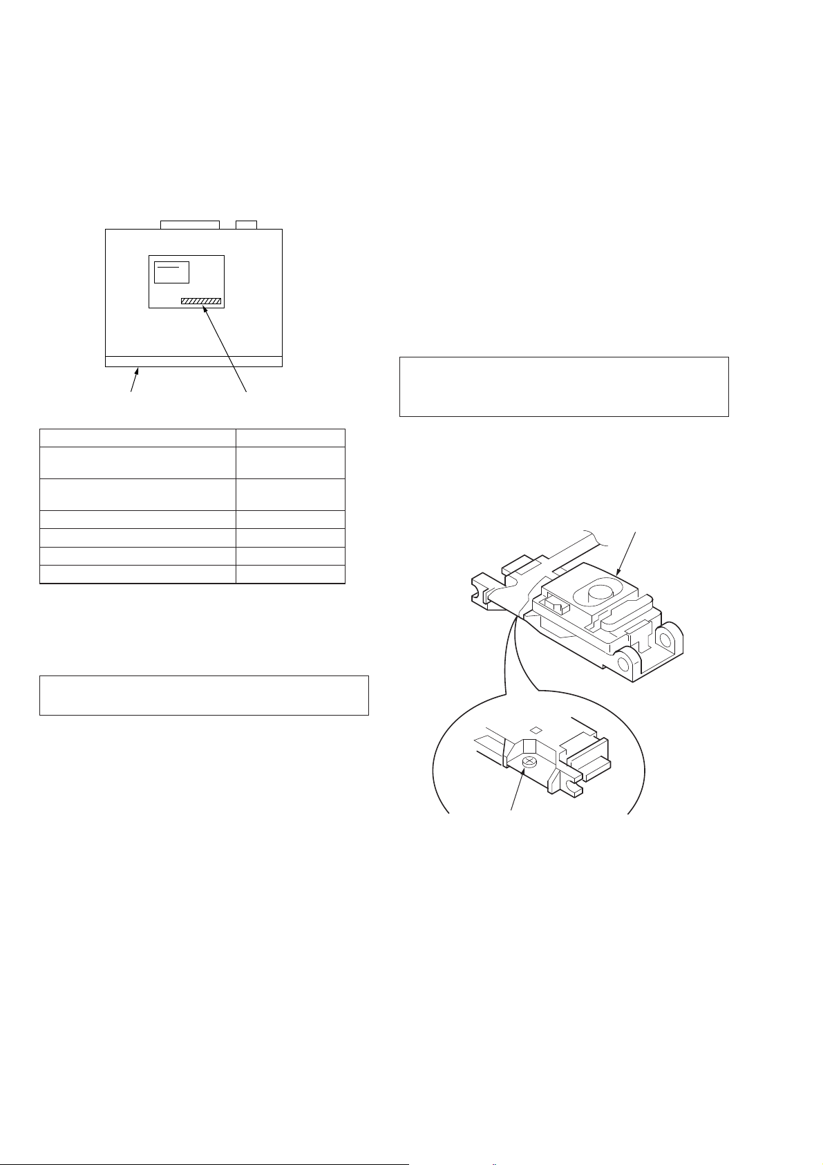
NOTES ON LASER DIODE EMISSION CHECK
The laser beam on this model is concentrated so as to be focused
on the disc refl ective surface by the objective lens in the optical
pickup block. Therefore, when checking the laser diode emission,
observe from more than 30 cm away from the objective lens.
NOTES ON CHIP COMPONENT REPLACEMENT
• Never reuse a disconnected chip component.
• Notice that the minus side of a tantalum capacitor may be
damaged by heat.
TEST DISCS
Please use the following test discs for the check on the CD
section.
YDES-18 (Part No. 3-702-101-01)
PATD-012 (Part No. 4-225-203-01)
CAUTION
Use of controls or adjustments or performance of procedures
other than those specifi ed herein may result in hazardous radia-
tion exposure.
If the optical pick-up block is defective, please replace the whole
optical pick-up block.
Never turn the semi-fi xed resistor located at the side of optical
pick-up block.
optical pick-up
NOTES ON HANDLING THE OPTICAL PICK-UP
BLOCK OR BASE UNIT
The laser diode in the optical pick-up block may suffer electrostatic break-down because of the potential difference generated by the
charged electrostatic load, etc. on clothing and the human body.
During repair, pay attention to electrostatic break-down and also
use the procedure in the printed matter which is included in the
repair parts.
The fl exible board is easily damaged and should be handled with
care.
SAFETY-RELATED COMPONET WARNING!
COMPONENTS IDENTIFIED BY MARK 0 OR DOTTED LINE
WITH MARK 0 ON THE SCHEMATIC DIAGRAMS AND IN
THE PARTS LIST ARE CRITICAL TO SAFE OPERATION.
REPLACE THESE COMPONENTS WITH SONY PARTS
WHOSE PART NUMBERS APPEAR AS SHOWN IN THIS
MANUAL OR IN SUPPLEMENTS PUBLISHED BY SONY.
semi-fixed resistor
2
CDX-GT48UM/GT480U/GT480US/GT484US
This compact disc player is classifi ed as a CLASS 1 LASER
product. The CLASS 1 LASER PRODUCT label is located on the
exterior.
This label is located on the bottom of the chassis.
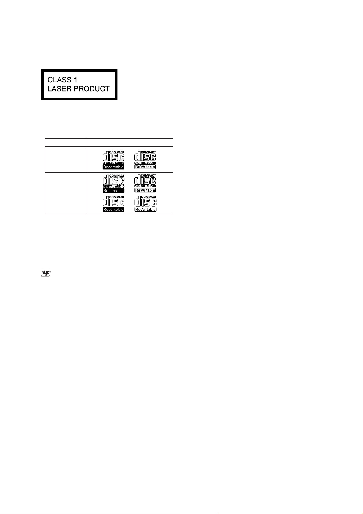
• CD Playback
You can play CD-DA (also containing CD TEXT) and CDR/CD-RW (MP3/WMA/AAC fi les).
Type of disc Label on the disc
CD-DA
MP3
WMA
AAC
UNLEADED SOLDER
Boards requiring use of unleaded solder are printed with the leadfree mark (LF) indicating the solder contains no lead.
(Caution: Some printed circuit boards may not come printed with
the lead free mark due to their particular size)
: LEAD FREE MARK
Unleaded solder has the following characteristics.
• Unleaded solder melts at a temperature about 40 °C higher
than ordinary solder.
Ordinary soldering irons can be used but the iron tip has to be
applied to the solder joint for a slightly longer time.
Soldering irons using a temperature regulator should be set to
about 350 °C.
Caution: The printed pattern (copper foil) may peel away if
the heated tip is applied for too long, so be careful!
• Strong viscosity
Unleaded solder is more viscous (sticky, less prone to fl ow)
than ordinary solder so use caution not to let solder bridges
occur such as on IC pins, etc.
• Usable with ordinary solder
It is best to use only unleaded solder but unleaded solder may
also be added to ordinary solder.
TABLE OF CONTENTS
1. SERVICE NOTE ...................................................... 4
2. GENERAL
Location of Controls ....................................................... 5
Connections .................................................................... 6
3. DISASSEMBLY
3-1. Sub Panel Assy ............................................................... 9
3-2. CD Mechanism Block ..................................................... 9
3-3. Main Board ..................................................................... 10
3-4. Servo Board .................................................................... 10
3-5. Chassis (T) Sub Assy ...................................................... 11
3-6. Roller Arm Assy .............................................................. 11
3-7. Chassis (OP) Assy ........................................................... 12
3-8. Chucking Arm Sub Assy ................................................. 12
3-9. Sled Motor Assy .............................................................. 13
3-10. Optical Pick-up Section .................................................. 14
3-11. Optical Pick-up ............................................................... 14
4. DIAGRAMS
4-1. Block Diagram –Main Section– ..................................... 15
4-2. Block Diagram –Display Section– ................................. 16
4-3. Printed Wiring Board –Main Section– ............................ 18
4-4. Schematic Diagram –Main Section (1/3)– ...................... 19
4-5. Schematic Diagram –Main Section (2/3)– ...................... 20
4-6. Schematic Diagram –Main Section (3/3)– ...................... 21
4-7. Printed Wiring Boards –Key Section– ............................ 22
4-8. Schematic Diagram –Key Section– ................................ 23
5. EXPLODED VIEWS
5-1. Main Section ................................................................... 29
5-2. Front Panel Section ......................................................... 30
5-3. CD Mechanism Section (MG-101Y-188//C) .................. 31
6. ELECTRICAL PARTS LIST .................................. 32
3
CDX-GT48UM/GT480U/GT480US/GT484US
SECTION 1
SERVICE NOTE
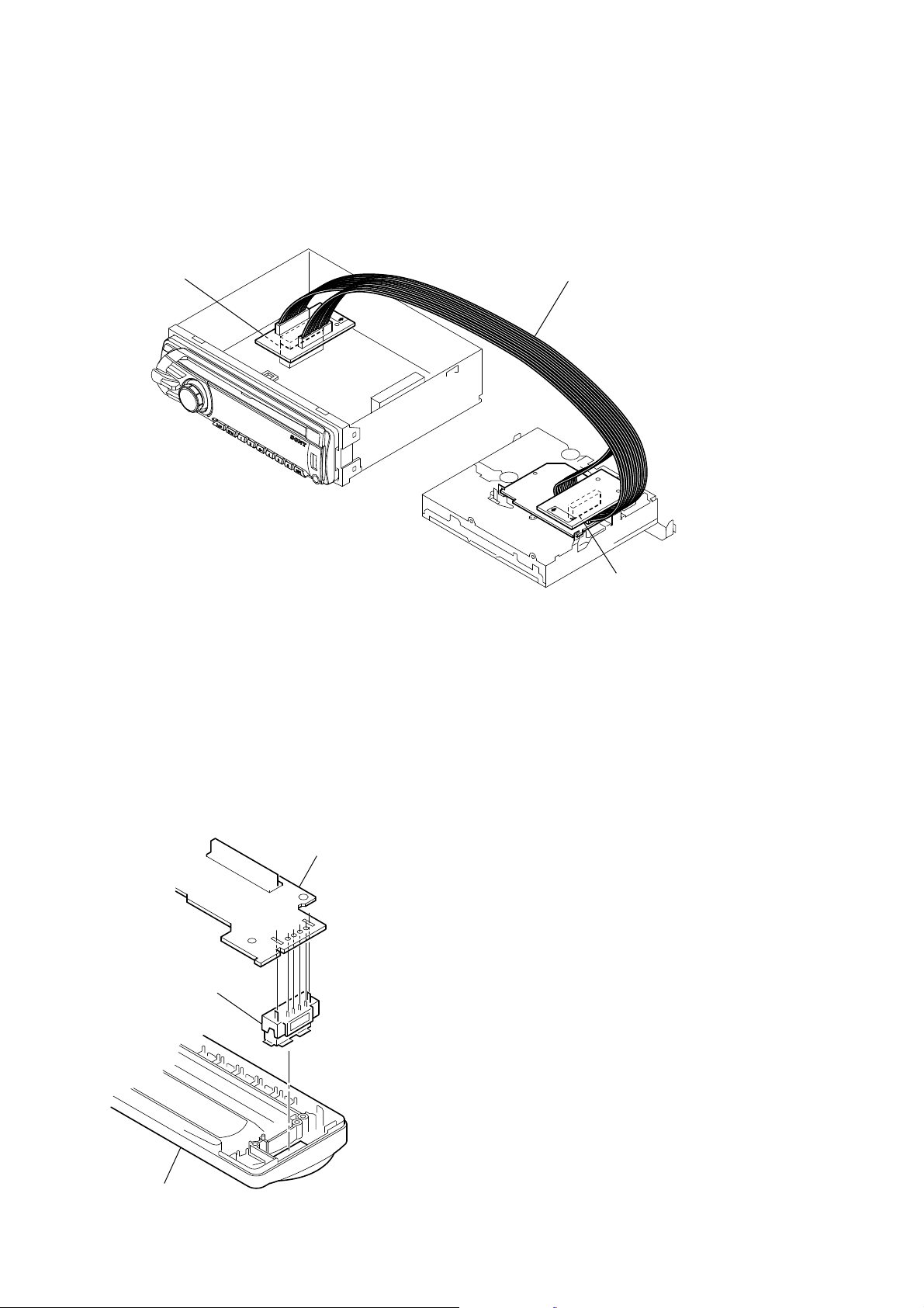
EXTENSION CABLE AND SERVICE POSITION
When repairing or servicing this set, connect the jig (extension
cable) as shown below.
• Connect the MAIN board (CN701) and the SERVO board
(CN401) with the extension cable (Part No. J-2502-076-1).
MAIN BOARD
CN701
J-2502-076-1
NOTE FOR REPLACEMENT OF THE USB CONNECTOR
(CN902)
To replace the USB connector requires alignment.
1. Insert the USB connector into the front panel.
2. Place the KEY board on the front panel and align the terminals
of the USB connector with the holes in the KEY board.
3. Solder the four terminals of the connector.
KEY board
USB (socket) connector
SERVO BOARD
CN401
NOTE FOR REPLACEMENT OF THE SERVO BOARD
When repairing, the complete SERVO board (Part No.
A-1555-002-A) should be replaced since any parts in the SERVO
board cannot be repaired.
NOTE FOR THE 20-PIN CONNECTOR (CN901)
Do not use alcohol to clean the 20-pin connector (CN901) connecting the front panel with the main body.
Do not touch the connector directly with your bare hand. Poor contact may be caused.
front panel
4
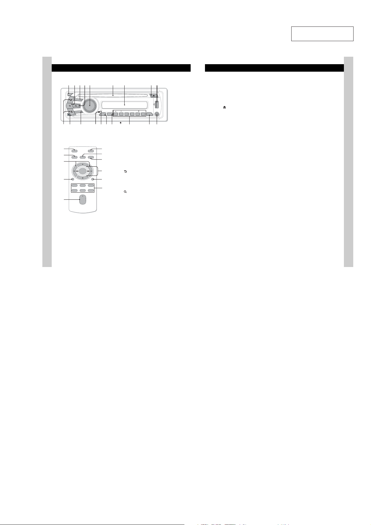
• LOCATION OF CONTROLS
R
R
RMX
R
R
R
R
R
R
Location of controls and basic operations
Main unit
OFF
SEEK
SOURCE
MODE
SEEK
BR
T
Card remote commander
RM-X151
OFF
XB
XT
XE
SOURCE
DSPL
132
465
SEL
+
–
+
VOL
–
6
PUSH ENTER/ SELECT
E
ATT
MODE
SCRL
ALBMARTIST TRACK SHUF ZAP
REP SHUF SCRL
ALBM
1 2 3 4 5 6
BTMZAP
H
G
XG
XH
RT
XI
XK
XL
K
I
This section contains instructions on the location
of controls and basic operations. For details, see
the respective pages.
For USB device operation, see “USB devices” on
page 10.
The corresponding buttons on the card remote
commander control the same functions as those
on the unit.
" OFF button
To power off; stop the source.
# (BACK) button page 8
To return to the previous display.
$ SOURCE button
To power on; change the source (Radio/CD/
USB/AUX).
% (BROWSE) button page 8
To enter the Quick-BrowZer mode.
& Control dial/select button
To adjust volume (rotate); select setup items
(press and rotate).
' Disc slot
Insert the disc (label side up), playback
starts.
( Display window
) ;(eject) button
To eject the disc.
* USB terminal page 10
To connect to the USB device.
CDX-GT48UM/GT480U/GT480US/GT484US
SECTION 2
GENERAL
+ SEEK +/– buttons
CD/USB:
LOUDDISCREGTPTAAF
+
DM
AUX
PAUSE
DM
DSPL
L
To skip tracks (press); sk ip tra cks
continuously (press, then press again within
about 1 second and hold); reverse/fastforward a track (press and hold).
Radio:
To tune in stations automatically (p ress); f ind
a station manually (press and hold).
, (front panel release) button page 5
- MODE button page9
To select the radio band (FM/AM).
. Receptor for the card remote
commander
/ RESET button (located behind the front
panel) page 4
0 ZAP button page 9
To enter ZAPPIN™ mode.
1 BTM button page 9
To start the BTM function (press and ho l d ) .
2 Frequency select switch (located on the
bottom of the unit)
See “Frequency select switch” in the
supplied installation/connections manual.
3 Number buttons
CD/USB:
/: ALBM –/+ (during MP3/WMA /
AAC playback)
To skip albums (press); skip albums
continuously (press and hold).
: REP page 10, 11
: SHUF page 10, 11
: DM+
Improves digitally compressed sound,
such as MP3.
To activate the DM+ function, set
“ON.” To cancel, set “OFF.”
: PAUS E
To pause play back. To cancel , press
again.
Radio:
To receive stored stations (press); store
stations (press and hold).
4 DSPL (display)/SCRL (scroll) button
page 10, 11
To change display items (press); sc roll the
display item (press and hold).
5 AUX inpu t jack page 13
To connect a portable audio device.
This section is extracted
from instruction manual.
The following buttons on the card remote
commander have also differ ent b ut ton s/ func ti ons
from the unit. Remove the insulation film before
use (page 4).
XB ()/ () buttons
To control radio/CD/USB, the same as
4&&, –/+ on the unit.
Setup, sound setting, etc., can be operated by
.
XT D
SPL (display) button page 10, 11
hange display items .
To c
XE
VOL (volume) +/– button
To adjust volume.
XG ATT ( atte nua te) but ton
To attenuate the sound. To cancel, press
again.
XH SEL (select) button
The same as the select button on the unit.
XI . (+)/N (–) buttons
To control CD/USB, the same as /
(ALBM –/+) on the unit.
Setup, sound setting, etc., can be operated by
.N.
XK SCRL (scroll) button
To scroll the display item.
XL Number buttons
To receive stored stations (press); store
stations (press and hold).
Note
If the unit is turned off and the display disappea rs, it
cannot be operated with the card remo te commander
unless 4063$& on the unit is pressed, or a disc is
inserted to activate the unit first.
7
5
CDX-GT48UM/GT480U/GT480US/GT484US
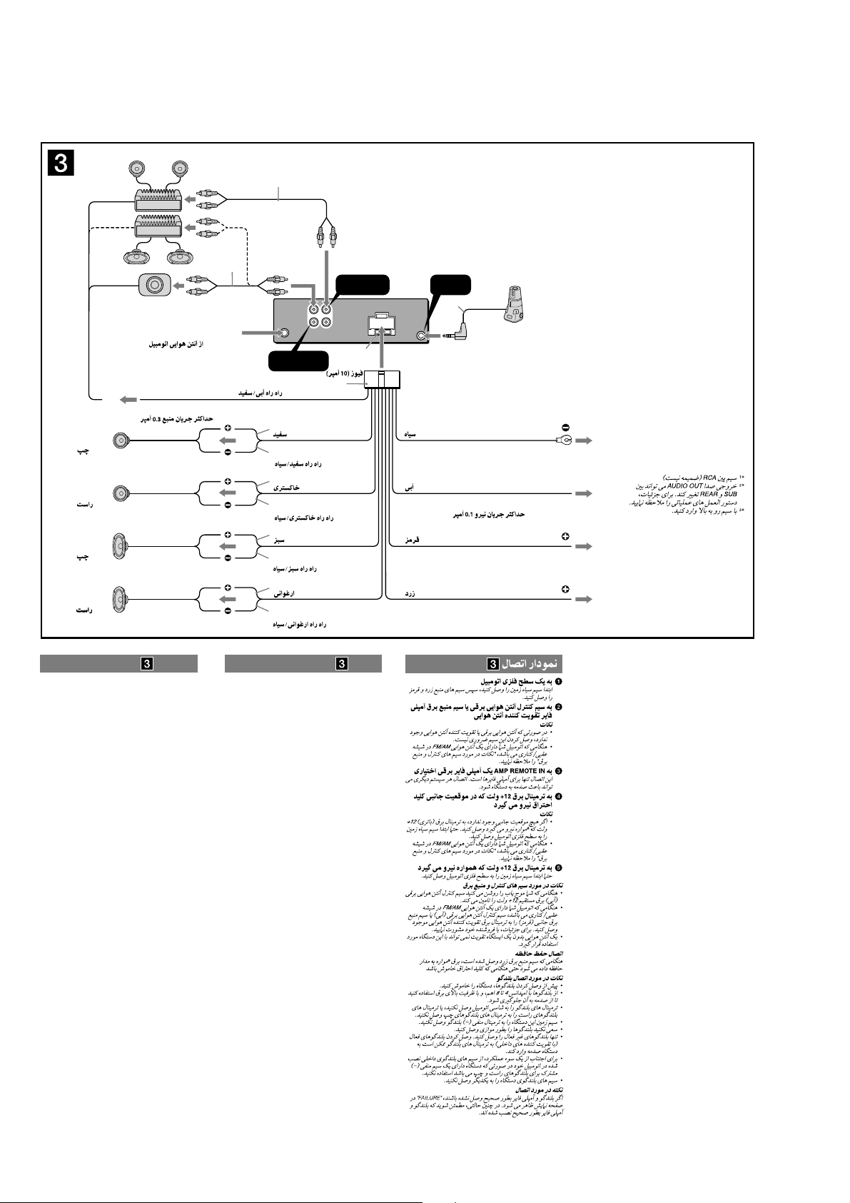
• CONNECTION
• Except CDX-GT480US: Argentina model
1
*
1
Left
Izquierdo
Right
Derecho
Left
Izquierdo
Right
Derecho
from car antenna (aerial)
desde la antena del automóvil
AMP REM
Max. supply current 0.3 A
Corriente máx. de alimentación de 0,3 A
*
REAR / SUB
AUDIO OUT
Blue/white striped
Con rayas azules y blancas
White
Blanco
White/black striped
Con rayas blancas y negras
Gray
Gris
Gray/black striped
Con rayas grises y negras
Green
Verde
Green/black striped
Con rayas verdes y negras
Purple
Morado
Purple/black striped
Con rayas moradas y negras
REAR/SUB FRONT
AUDIO OUT
*
2
FRONT
AUDIO OUT
L
R
Fuse (10 A)
Fusible (10 A)
Black
Negro
Blue
Azul
Red
Rojo
Yellow
Amarillo
REMOTE
IN
3
*
Max. supply current 0.1 A
Corriente máx. de alimentación de 0,1 A
ANT REM
*1 RCA pin cord (not supplied)
2
*
AUDIO OUT can be switched SUB or
REAR. For details, see the supplied
Operating Instructions.
3
*
Inser t with the cord upwards.
1
Cable con terminales RCA (no
*
suministrado)
2
*
AUDIO OUT (salida de audio) puede
cambiarse a SUB o REAR. Para
obtener información, consulte el
manual de instrucciones suministrado.
3
*
Inser tar con el cable hacia arriba.
Connection diagram
To a metal surface of the car
First connect the black ground (earth) lead, then connect the
yellow, and red power supply leads.
To the power antenna (aerial) control lead or
power supply lead of antenna (aerial) booster
amplifier
Notes
• It is not necessary to connect this lead if there is no power
antenna (aerial) or antenna (aerial) booster, or with a
manually-operated telescopic antenna (aerial).
• When your car has a built-in FM/AM antenna (aerial) in
the rear/side glass, see “Notes on the control and power
supply leads.”
To AMP REMOTE IN of an optional power
amplifier
This connection is only for amplifiers. Connecting any other
system may damage the unit.
To the +12 V power terminal which is
energized in the accessory position of the
ignition key switch
Notes
• If there is no accessory position, connect to the +12 V
power (battery) terminal which is energized at all times.
Be sure to connect the black ground (earth) lead to a
metal surface of the car first.
• When your car has a built-in FM/AM antenna (aerial) in
the rear/side glass, see “Notes on the control and power
supply leads.”
To the +12 V power terminal which is
energized at all times
Be sure to connect the black ground (earth) lead to a metal
surface of the car first.
Notes on the control and power supply leads
• The power antenna (aerial) control lead (blue) supplies +12 V
DC when you turn on the tuner.
• When your car has built-in FM/AM antenna (aerial) in the rear/
side glass, connect the power antenna (aerial) control lead
(blue) or the accessory power supply lead (red) to the power
terminal of the existing antenna (aerial) booster. For details,
consult your dealer.
• A power antenna (aerial) without a relay box cannot be used
with this unit.
Memory hold connection
When the yellow power supply lead is connected, power will
always be supplied to the memory circuit even when the ignition
switch is turned off.
Notes on speaker connection
• Before connecting the speakers, turn the unit off.
• Use speakers with an impedance of 4 to 8 ohms, and with
adequate power handling capacities to avoid its damage.
• Do not connect the speaker terminals to the car chassis, or
connect the terminals of the right speakers with those of the
left speaker.
• Do not connect the ground (earth) lead of this unit to the
negative (–) terminal of the speaker.
• Do not attempt to connect the speakers in parallel.
• Connect only passive speakers. Connecting active speakers
(with built-in amplifiers) to the speaker terminals may damage
the unit.
• To avoid a malfunction, do not use the built-in speaker leads
installed in your car if the unit shares a common negative (–)
lead for the right and left speakers.
• Do not connect the unit’s speaker leads to each other.
Note on connection
If speaker and amplifier are not connected correctly, “FAILURE”
appears in the display. In this case, make sure the speaker and
amplifier are connected correctly.
Diagrama de conexión
A una superficie metálica del automóvil
Conecte primero el cable de conexión a masa negro, y
después los cables amarillo y rojo de fuente de alimentación.
Al cable de control de la antena motorizada
o al cable de fuente de alimentación del
amplificador de señal de la antena
Notas
• Si no se dispone de antena motorizada ni de amplificador
de antena, o se utiliza una antena telescópica accionada
manualmente, no será necesario conectar este cable.
• Si el automóvil incorpora una antena de FM/AM en el
cristal trasero o lateral, consulte “Notas sobre los cables
de control y de fuente de alimentación”.
A AMP REMOTE IN de un amplificador de
potencia opcional
Esta conexión es sólo para amplificadores. La conexión de
cualquier otro sistema puede dañar la unidad.
Al terminal de alimentación de +12 V que
recibe energía en la posición de accesorio
del interruptor de encendido
Notas
• Si no hay posición de accesorio, conéctelo al terminal de
alimentación (batería) de +12 V que recibe energía sin
interrupción.
Asegúrese de conectar primero el cable de conexión a
masa negro a una superficie metálica del automóvil.
• Si el automóvil incorpora una antena de FM/AM en el
cristal trasero o lateral, consulte “Notas sobre los cables
de control y de fuente de alimentación”.
Al terminal de alimentación de +12 V que
recibe energía sin interrupción
Asegúrese de conectar primero el cable de conexión a masa
negro a una superficie metálica del automóvil.
Notas sobre los cables de control y de fuente de
alimentación
• El cable de control de la antena motorizada (azul) suministrará
cc de +12 V cuando conecte la alimentación del sintonizador.
• Si el automóvil dispone de una antena de FM/AM incorporada
en el cristal trasero o lateral, conecte el cable de control de
antena motorizada (azul) o el cable de fuente de alimentación
auxiliar (rojo) al terminal de alimentación del amplificador de
antena existente. Para obtener más información, consulte a su
distribuidor.
• Con esta unidad no es posible utilizar una antena motorizada
sin caja de relé.
Conexión para protección de la memoria
Si conecta el cable de fuente de alimentación amarillo, el circuito
de la memoria recibirá siempre alimentación, aunque apague el
interruptor de encendido.
Notas sobre la conexión de los altavoces
• Antes de conectar los altavoces, desconecte la alimentación
de la unidad.
• Utilice altavoces con una impedancia de 4 a 8 ? con la
capacidad de potencia adecuada para evitar que se dañen.
• No conecte los terminales de altavoz al chasis del automóvil,
ni conecte los terminales del altavoz derecho con los del
izquierdo.
• No conecte el cable de conexión a masa de esta unidad al
terminal negativo (–) del altavoz.
• No intente conectar los altavoces en paralelo.
• Conecte solamente altavoces pasivos. Si conecta altavoces
activos (con amplificadores incorporados) a los terminales de
altavoz, puede dañar la unidad.
• Para evitar fallas de funcionamiento, no utilice los cables de
altavoz incorporados instalados en el automóvil si la unidad
comparte un cable negativo común (–) para los altavoces
derecho e izquierdo.
• No conecte los cables de altavoz de la unidad entre sí.
Nota sobre la conexión
Si el altavoz y el amplificador no están conectados
correctamente, aparecerá “FAILURE” en la pantalla. Si es así,
compruebe la conexión de ambos dispositivos.
6
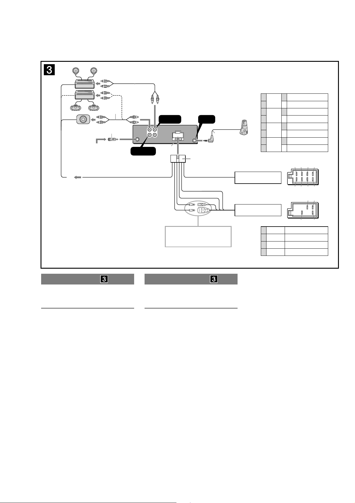
• CONNECTION
L
R
REAR/SUB FRONT
AUDIO OUT
"
REMOTE
IN
13 57
24 68
57
48
FRONT
AUDIO OUT
REAR / SUB
AUDIO OUT
*
3
• CDX-GT480US: Argentina model
CDX-GT48UM/GT480U/GT480US/GT484US
2
*
2
*
*1 from car antenna (aerial)
desde la antena del automóvil
AMP REM
Max. supply current 0.3 A
Corriente máx. de alimentación de 0,3 A
*1 Note for the antenna (aerial) connecting
If your car antenna (aerial) is an ISO (International
Organisation for Standardisation) type, use the supplied
adaptor to connect it. First connect the car antenna
(aerial) to the supplied adaptor, then connect it to the
antenna (aerial) jack of the master unit.
2
*
RCA pin cord (not supplied)
3
AUDIO OUT can be switched SUB or REAR. For details,
*
see the supplied Operating Instructions.
4
*
Inser t with the cord upwards.
1
*
Nota sobre la conexión de la antena
Si la antena del automóvil es del tipo ISO (International
Organization for Standardization), emplee el adaptador
suministrado para conectarla. En primer lugar, conecte
la antena del automóvil al adaptador suministrado y, a
continuación, a la toma de antena de la unidad principal.
2
*
Cable con terminales RCA (no suministrado)
3
AUDIO OUT (salida de audio) puede cambiarse a SUB o
*
REAR. Para obtener información, consulte el manual de
instrucciones suministrado.
4
*
Inser tar con el cable hacia arriba.
Fuse (10 A)
Fusible (10 A)
Blue/white striped
Con rayas azules y blancas
4
*
See “Power connection diagram” on the reverse
side for details.
Para obtener más información, consulte el
“Diagrama de conexión de la alimentación” que
encontrará al dorso.
1
Purple
Morado
2–
3
Gray
Gris
4–
5
White
Blanco
6–
7
Green
Verde
8–
Negative polarity positions 2, 4, 6, and 8 have striped leads.
Los cables de las posiciones de polaridad negativa 2, 4, 6 y 8
son rayados.
from the car’s speaker connector
desde un conector de altavoces
del automóvil
from the car’s power connector
desde un conector de
alimentación auxiliar del automóvil
Yellow
4
Amarillo
Blue
5
Azul
Red
7
Rojo
Black
8
Negro
Positions 1, 2, 3 and 6 do not have pins.
Las posiciones 1, 2, 3 y 6 no tienen pines.
Speaker, Rear, Right
+
Altavoz, posterior, derecho
Speaker, Rear, Right
Altavoz, posterior, derecho
Speaker, Front, Right
+
Altavoz, frontal, derecho
Speaker, Front, Right
Altavoz, frontal, derecho
Speaker, Front, Left
+
Altavoz, frontal, izquierdo
Speaker, Front, Left
Altavoz, frontal, izquierdo
Speaker, Rear, Left
+
Altavoz, posterior, izquierdo
Speaker, Rear, Left
Altavoz, posterior, izquierdo
continuous power supply
fuente de alimentación continua
power antenna (aerial) control
control de la antena motorizada
switched power supply
fuente de alimentación conmutada
earth
masa
Connection diagram
" To AMP REMOTE IN of an optional power
amplifier
This connection is only for amplifiers. Connecting any other
system may damage the unit.
Warning
If you have a power antenna (aerial) without a relay box,
connecting this unit with the supplied power connecting
lead may damage the antenna (aerial).
Notes on the control and power supply leads
• The power antenna (aerial) control lead (blue) supplies +12 V
DC when you turn on the tuner.
• When your car has built-in FM/AM antenna (aerial) in the rear/
side glass, connect the power antenna (aerial) control lead
(blue) or the accessory power supply lead (red) to the power
terminal of the existing antenna (aerial) booster. For details,
consult your dealer.
• A power antenna (aerial) without a relay box cannot be used
with this unit.
Memory hold connection
When the yellow power supply lead is connected, power will
always be supplied to the memory circuit even when the ignition
switch is turned off.
Notes on speaker connection
• Before connecting the speakers, turn the unit off.
• Use speakers with an impedance of 4 to 8 ohms, and with
adequate power handling capacities to avoid its damage.
• Do not connect the speaker terminals to the car chassis, or
connect the terminals of the right speakers with those of the
left speaker.
• Do not connect the ground (earth) lead of this unit to the
negative (–) terminal of the speaker.
• Do not attempt to connect the speakers in parallel.
• Connect only passive speakers. Connecting active speakers
(with built-in amplifiers) to the speaker terminals may damage
the unit.
• To avoid a malfunction, do not use the built-in speaker leads
installed in your car if the unit shares a common negative (–)
lead for the right and left speakers.
• Do not connect the unit’s speaker leads to each other.
Note on connection
If speaker and amplifier are not connected correctly, “FAILURE”
appears in the display. In this case, make sure the speaker and
amplifier are connected correctly.
Diagrama de conexión
" A AMP REMOTE IN de un amplificador de
potencia opcional
Esta conexión es sólo para amplificadores. La conexión de
cualquier otro sistema puede dañar la unidad.
Advertencia
Si la antena motorizada no dispone de caja de relé, es
posible que la conexión de esta unidad mediante el cable
de alimentación suministrado provoque daños en la
antena.
Notas sobre los cables de control y de fuente de
alimentación
• El cable de control de la antena motorizada (azul) suministrará
cc de +12 V cuando conecte la alimentación del sintonizador.
• Si el automóvil dispone de una antena de FM/AM incorporada
en el cristal trasero o lateral, conecte el cable de control de
antena motorizada (azul) o el cable de fuente de alimentación
auxiliar (rojo) al terminal de alimentación del amplificador de
antena existente. Para obtener más información, consulte a su
distribuidor.
• Con esta unidad no es posible utilizar una antena motorizada
sin caja de relé.
Conexión para protección de la memoria
Si conecta el cable de fuente de alimentación amarillo, el circuito
de la memoria recibirá siempre alimentación, aunque apague el
interruptor de encendido.
Notas sobre la conexión de los altavoces
• Antes de conectar los altavoces, desconecte la alimentación
de la unidad.
• Utilice altavoces con una impedancia de 4 a 8 ? con la
capacidad de potencia adecuada para evitar que se dañen.
• No conecte los terminales de altavoz al chasis del automóvil,
ni conecte los terminales del altavoz derecho con los del
izquierdo.
• No conecte el cable de conexión a masa de esta unidad al
terminal negativo (–) del altavoz.
• No intente conectar los altavoces en paralelo.
• Conecte solamente altavoces pasivos. Si conecta altavoces
activos (con amplificadores incorporados) a los terminales de
altavoz, puede dañar la unidad.
• Para evitar fallas de funcionamiento, no utilice los cables de
altavoz incorporados instalados en el automóvil si la unidad
comparte un cable negativo común (–) para los altavoces
derecho e izquierdo.
• No conecte los cables de altavoz de la unidad entre sí.
Nota sobre la conexión
Si el altavoz y el amplificador no están conectados
correctamente, aparecerá “FAILURE” en la pantalla. Si es así,
compruebe la conexión de ambos dispositivos.
7
CDX-GT48UM/GT480U/GT480US/GT484US
SECTION 3
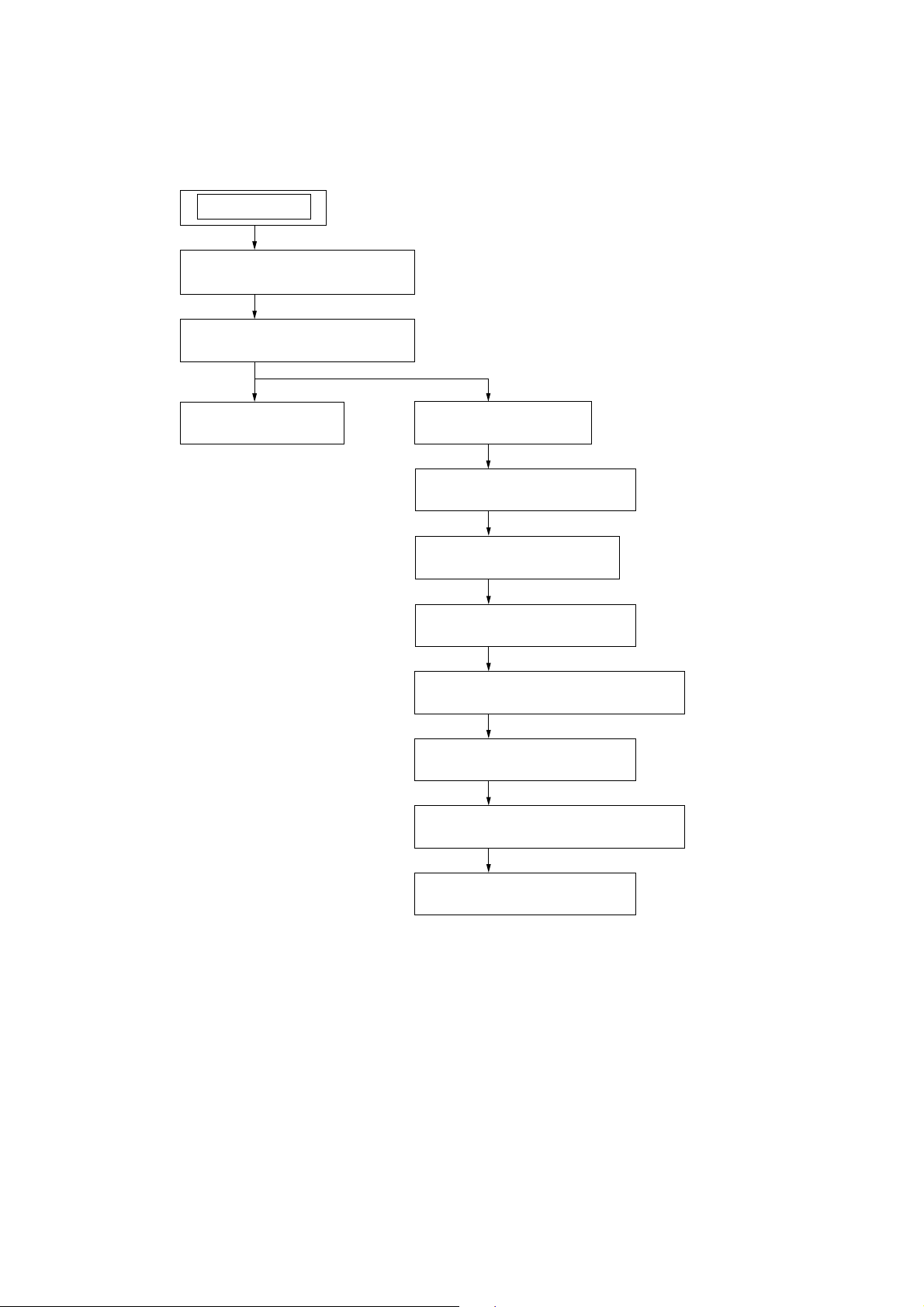
DISASSEMBLY
• This set can be disassembled in the order shown below.
SET
3-1. SUB PANEL ASSY
(Page 9)
3-2. CD MECHANISM BLOCK
(Page 9)
3-3. MAIN BOARD
(Page 10)
3-4. SERVO BOARD
(Page 10)
3-5. CHASSIS (T) SUB ASSY
(Page 11)
3-6. ROLLER ARM ASSY
(Page 11)
3-7. CHASSIS (OP) ASSY
(Page 12)
3-8. CHUCKING ARM SUB ASSY
(Page 12)
3-9. SLED MOTOR ASSY
(Page 13)
3-10. OPTICAL PICK-UP SECTION
(Page 14)
3-11. OPTICAL PICK-UP
(Page 14)
8
CDX-GT48UM/GT480U/GT480US/GT484US
Note: Follow the disassembly procedure in the numerical order shown below.
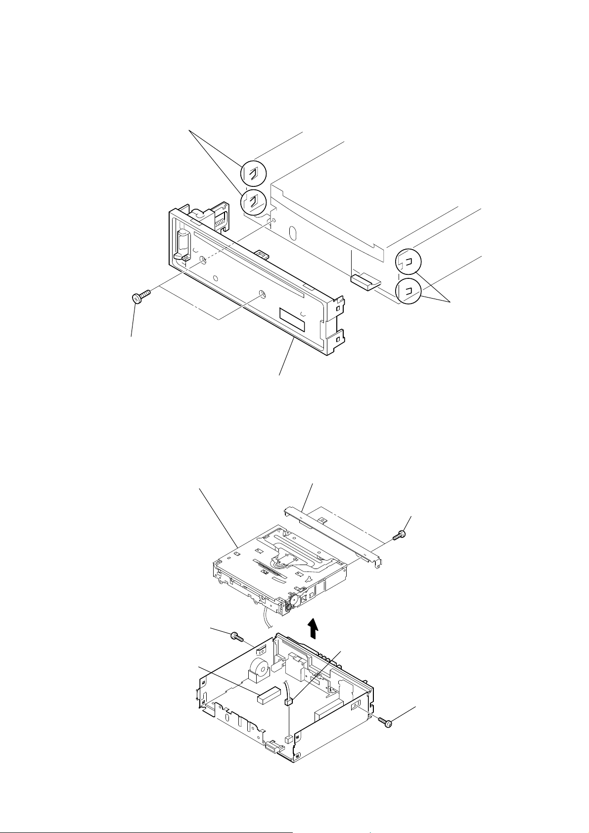
3-1. SUB PANEL ASSY
two claws
two claws
two
screws
(+PTT 2.6
×
6)
3-2. CD MECHANISM BLOCK
CD mechanism block
screw
(+PTT 2.6
×
6)
sub panel assy
bracket (CD)
two
screws
(+PTT 2.6
×
4)
CN701
CN501 (3P)
screw
(+PTT 2.6
×
6)
9
CDX-GT48UM/GT480U/GT480US/GT484US
3-3. MAIN BOARD
two
(+PTT 2.6
screws
×
8)
screws
two
(+P 2.6
×
8)
two
screws
(+PTT 2.6
×
10)
three
(+BTT)
screws
insulating sheet
MAIN board
heat sink
screw
(+P 2.6
screw
(+PTT 2.6
×
10)
×
10)
3-4. SERVO BOARD
WHT
RED
BLK
WHT
RED
BLK
RED
ORG
BLU
YEL
GRY
Remove the eleven solders.
SERVO board
claw
toothed lock screw
(M 1.7 × 2.5)
toothed lock screw
(M 1.7 × 2.5)
SERVO board
optical pick-up (16 core)
(CN101)
claw
10
3-5. CHASSIS (T) SUB ASSY
CDX-GT48UM/GT480U/GT480US/GT484US
two precision
(+P 1.7
×
2.2)
screws
claw
two precision
(+P 1.7
×
2.2)
chassis (T) sub assy
screws
3-6. ROLLER ARM ASSY
spring (RAL)
roller arm assy
gear (RA1)
washer
spring (RAR)
11
CDX-GT48UM/GT480U/GT480US/GT484US
3-7. CHASSIS (OP) ASSY
tension spring (KF)
two coil springs (damper) (natural)
slider (R)
chassis (OP) assy
coil spring (damper) (green)
lever (D)
gear (LE1)
3-8. CHUCKING ARM SUB ASSY
spring
Note: Have this portion receive the chassis.
chucking arm sub assy
Note: Have this portion receive the chassis.
Note: Be careful not to touch the turn table.
12
 Loading...