

Page 1
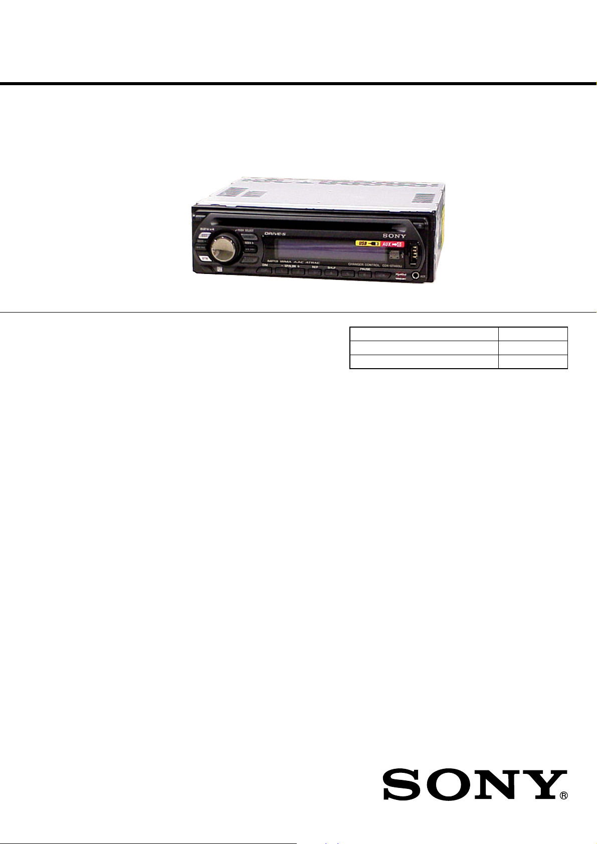
CDX-GT41UW/GT410U/
GT460U/GT460US
SERVICE MANUAL
Ver. 1.2 2007.03
(Photo: CDX-GT460U)
• The tuner and CD sections have no adjustments.
AUDIO POWER SPECIFICATIONS (US MODEL)
POWER OUTPUT AND TOTAL HARMONIC DISTORTION
23.2 watts per channel minimum continuous average power into
4 ohms, 4 channels driven from 20 Hz to 20 kHz with no more
than 5% total harmonic distortion.
US Model
Canadian Model
CDX-GT41UW/GT410U
E Model
CDX-GT460U/GT460US
Chinese Model
CDX-GT460U
Model Name Using Similar Mechanism NEW
CD Drive Mechanism Type MG-101U-188//Q
Optical Pick-up Name DAX-25A
CD player section
Signal-to-noise ratio 120 dB
Frequency response 10 – 20,000 Hz
Wow and flutter Below measurable limit
Tuner section
FM
Tuning range GT41UW/GT410U:
87.5 – 107.9 MHz
GT460U/GT460US:
87.5 – 108.0 MHz (at 50 kHz step)
87.5 – 107.9 MHz (at 200 kHz step)
FM tuning interval GT460U/GT460US:
50 kHz/200 kHz switchable
Antenna terminal External antenna connector
Intermediate frequency 10.7 MHz/450 kHz
Usable sensitivity 9 dBf
Selectivity 75 dB at 400 kHz
Signal-to-noise ratio 67 dB (stereo), 69 dB (mono)
Harmonic distortion at 1 kHz
0.5% (stereo), 0.3% (mono)
Separation 35 dB at 1 kHz
Frequency response 30 – 15,000 Hz
SPECIFICATIONS
AM
Tuning range GT41UW/GT410U:
530 – 1,710 kHz
GT460U/GT460US:
531 – 1,602 kHz (at 9 kHz step)
530 – 1,710 kHz (at 10 kHz step)
AM tuning interval GT460U/GT460US:
9 kHz/10 kHz switchable
Antenna terminal External antenna connector
Intermediate frequency 10.7 MHz/450 kHz
Sensitivity 30 µV
USB player section
Interface USB (Full-speed)
Maximum current 500 mA
Power amplifier section
Outputs Speaker outputs (sure seal connectors)
Speaker impedance 4 – 8 ohms
Maximum power output
52 W × 4 (at 4 ohms)
– Continued on next page –
9-887-470-03
2007C04-1
© 2007.03
FM/AM COMPACT DISC PLAYER
Sony Corporation
eVehicle Division
Published by Sony Techno Create Corporation
Page 2
CDX-GT41UW/GT410U/GT460U/GT460US
Ver. 1.1
General
Outputs Audio outputs terminal (sub/rear switchable)
Inputs BUS control input terminal
Tone controls Low: ±10 dB at 60 Hz (XPLOD)
Power requirements 12 V DC car battery (negative ground)
Dimensions Approx. 178 × 50 × 179 mm
Mounting dimensions Approx. 182 × 53 × 162 mm
Mass Approx. 1.2 kg (2 lb. 11 oz.)
Supplied accessories Card remote commander: RM-X151
Design and specifications are subject to change without
notice.
US and foreign patents licensed from Dolby
Laboratories.
Power antenna relay control terminal
Power amplifier control terminal
BUS audio input terminal
Antenna input terminal
AUX input jack (stereo mini jack)
Mid: ±10 dB at 1 kHz (XPLOD)
High: ±10 dB at 10 kHz (XPLOD)
(7
1/8 × 2 × 7 1/8 in.) (w/h/d)
(7 1/4 × 2 1/8 × 6 1/2 in.) (w/h/d)
Parts for installation and connections (1 set)
USB cap
SERVICE NOTES
Notes on Chip Component Replacement
•Never reuse a disconnected chip component.
•Notice that the minus side of a tantalum capacitor may be damaged
by heat.
TEST DISCS
Please use the following test discs for the check on the CD section.
YDES-18 (Part No. 3-702-101-01)
PATD-012 (Part No. 4-225-203-01)
CAUTION
Use of controls or adjustments or performance of procedures
other than those specified herein may result in hazardous
radiation exposure.
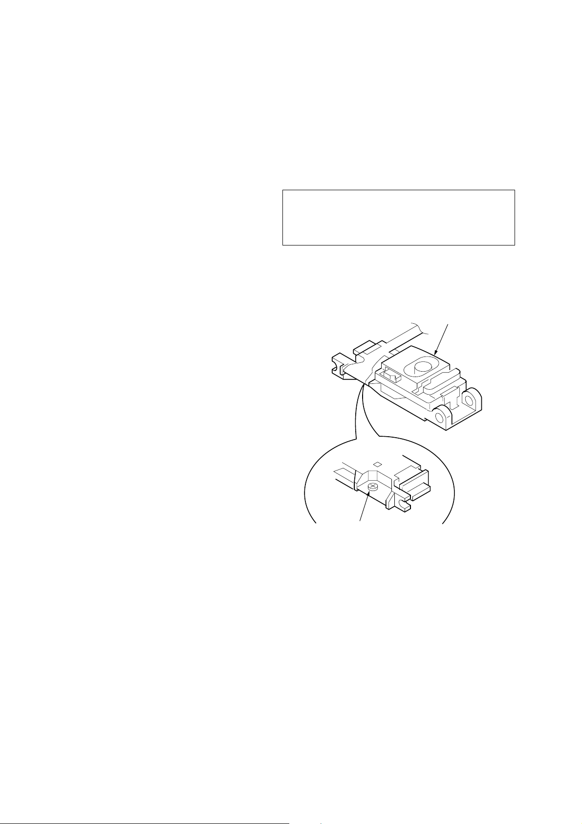
If the optical pick-up block is defective, please replace the whole
optical pick-up block.
Never turn the semi-fix ed resistor located at the side of optical pickup block.
optical pick-up
NOTES ON HANDLING THE OPTICAL PICK-UP BLOCK
OR BASE UNIT
The laser diode in the optical pick-up block may suffer electrostatic
breakdown because of the potential difference generated by the
charged electrostatic load, etc. on clothing and the human body.
During repair, pay attention to electrostatic breakdown and also use
the procedure in the printed matter which is included in the repair
parts.
The flexible board is easily damaged and should be handled with
care.
NOTES ON LASER DIODE EMISSION CHECK
The laser beam on this model is concentrated so as to be focused on
the disc reflective surface by the objective lens in the optical pickup block. Therefore, when checking the laser diode emission,
observe from more than 30 cm away from the objective lens.
semi-fixed resistor
SAFETY-RELATED COMPONENT WARNING!!
COMPONENTS IDENTIFIED BY MARK 0 OR DOTTED LINE
WITH MARK 0 ON THE SCHEMATIC DIAGRAMS AND IN
THE PARTS LIST ARE CRITICAL TO SAFE OPERATION.
REPLACE THESE COMPONENTS WITH SONY P ARTS WHOSE
PART NUMBERS APPEAR AS SHOWN IN THIS MANUAL OR
IN SUPPLEMENTS PUBLISHED BY SONY.
2
ATTENTION AU COMPOSANT AYANT RAPPORT
À LA SÉCURITÉ!!
LES COMPOSANTS IDENTIFIÉS P AR UNE MARQUE 0 SUR LES
DIAGRAMMES SCHÉMATIQUES ET LA LISTE DES PIÈCES
SONT CRITIQUES POUR LA SÉCURITÉ DE FONCTIONNEMENT.
NE REMPLACER CES COMPOSANTS QUE PAR DES PIÈCES
SONY DONT LES NUMÉROS SONT DONNÉS DANS CE MANUEL
OU DANS LES SUPPLÉMENTS PUBLIÉS PAR SONY.
Page 3
CDX-GT41UW/GT410U/GT460U/GT460US
D
This compact disc player is classified as a CLASS 1 LASER
product. The CLASS 1 LASER PRODUCT label is located on the
exterior.
E model
This label is located on the bottom of the chassis.
Chinese model
• CD playback
You can play CD-DA (also containing CD TEXT*), CD-R/CDRW (MP3/WMA/AAC files also containing Multi Session) and
ATRAC CD (ATRAC3 and ATRAC3plus format).
Type of discs Label on the disc
UNLEADED SOLDER
•
Boards requiring use of unleaded solder are printed with the leadfree mark (LF) indicating the solder contains no lead.
(Caution:Some printed circuit boards may not come printed with
the lead free mark due to their particular size.)
: LEAD FREE MARK
Unleaded solder has the following characteristics.
• Unleaded solder melts at a temperature about 40°C higher than
ordinary solder.
Ordinary soldering irons can be used but the iron tip has to be
applied to the solder joint for a slightly longer time.
Soldering irons using a temperature regulator should be set to
about 350°C.
Caution:The printed pattern (copper foil) may peel away if the
heated tip is applied for too long, so be careful!
• Strong viscosity
Unleaded solder is more viscous (sticky, less prone to flow)
than ordinary solder so use caution not to let solder bridges
occur such as on IC pins, etc.
• Usable with ordinary solder
It is best to use only unleaded solder but unleaded solder may
also be added to ordinary solder.
CD-DA
MP3
WMA
AAC
ATRAC CD
*A CD TEXT disc is a CD-DA that includes information such as
disc, artist and track name.
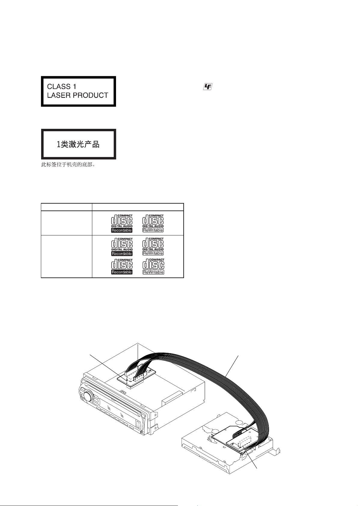
EXTENSION CABLE AND SERVICE POSITION
When repairing or servicing this set, connect the jig (extension cable)
as shown below.
• Connect the MAIN board (CN350) and the SER V O board (CN2)
with the extension cable (Part No. J-2502-076-1).
MAIN BOARD
CN350
J-2502-076-1
SERVO BOAR
CN2
3
Page 4
CDX-GT41UW/GT410U/GT460U/GT460US
d
Ver. 1.2
NOTE FOR REPLACEMENT OF THE SERVO BOARD
When repairing, the complete SERVO board (A-1206-357-A) should
be replaced since any parts in the SERVO board cannot be repaired.
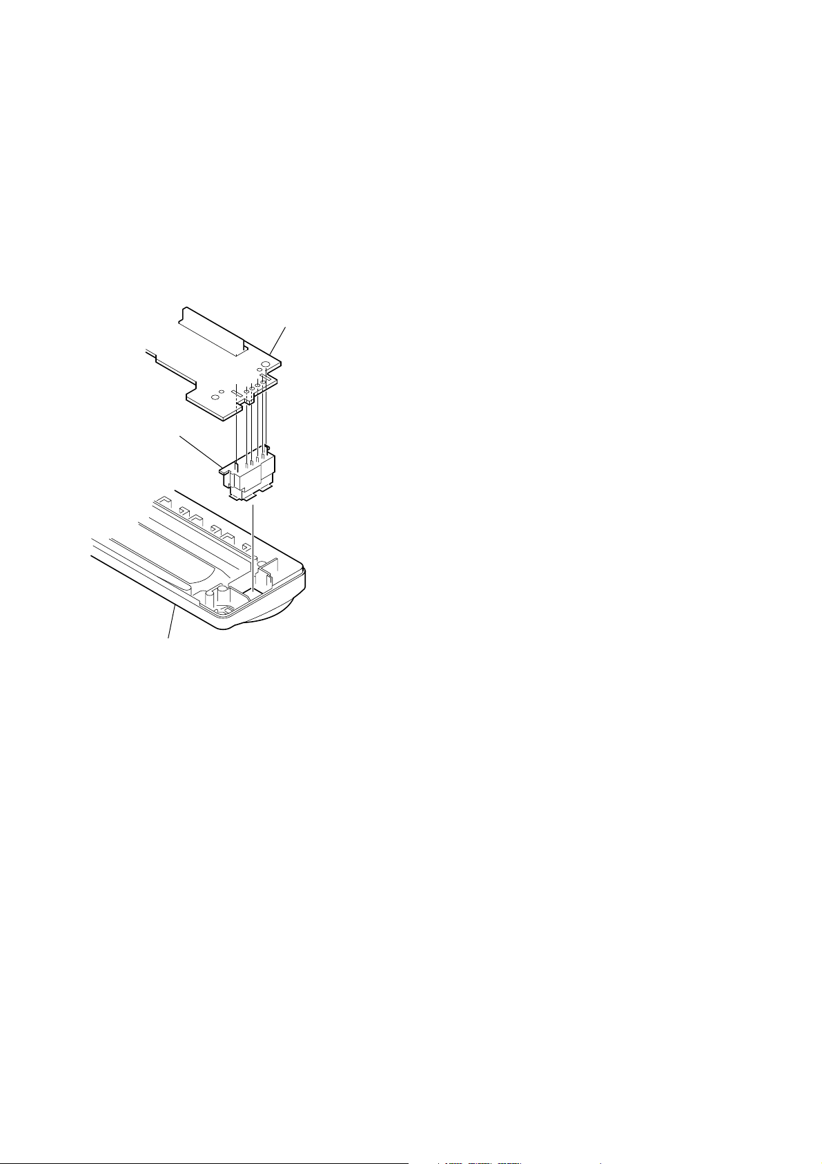
NOTE FOR REPLACEMENT OF THE USB CONNECTOR
(CN902)
To replace the USB connector requires alignment.
1. Insert the USB connector into the front panel.
2. Place the KEY board on the front panel and align the terminals
of the USB connector with the holes in the KEY board.
3. Solder the four terminals of the connector.
KEY boar
USB (socket) connector
TABLE OF CONTENTS
1. GENERAL
Location of Controls ........................................................ 5
Connections ..................................................................... 6
2. DISASSEMBLY
2-1. Sub Panel (FL) Assy ........................................................ 11
2-2. CD Mechanism Block ..................................................... 11
2-3. Main Board ...................................................................... 12
2-4. Servo Board ..................................................................... 12
2-5. Chassis (T) Sub Assy....................................................... 13
2-6. Roller Arm Assy .............................................................. 13
2-7. Chassis (OP) Assy ........................................................... 14
3. DIAGNOSIS FUNCTION ........................................ 15
4. DIAGRAMS
4-1. Block Diagram –Main Section– ...................................... 19
4-2. Block Diagram –Display Section– .................................. 20
4-3. Printed Wiring Board –Main Section– ............................ 22
4-4. Schematic Diagram –Main Section (1/3)– ...................... 23
4-5. Schematic Diagram –Main Section (2/3)– ...................... 24
4-6. Schematic Diagram –Main Section (3/3)– ...................... 25
4-7. Printed Wiring Board –Key Section– .............................. 26
4-8. Schematic Diagram –Key Section– ................................. 27
front panel
NOTE FOR THE 24-PIN CONNECTOR (CN901)
Do not use alcohol to clean the 24-pin connector (CN901) connecting
the front panel with the main body.
Do not touch the connector directly with your bare hand. Poor contact
may be caused.
5. EXPLODED VIEWS
5-1. Main Section .................................................................... 32
5-2. Front Panel Section ......................................................... 33
5-3. CD Mechanism Section (MG-101U-188//Q) .................. 34
6. ELECTRICAL PARTS LIST .................................. 35
4
Page 5
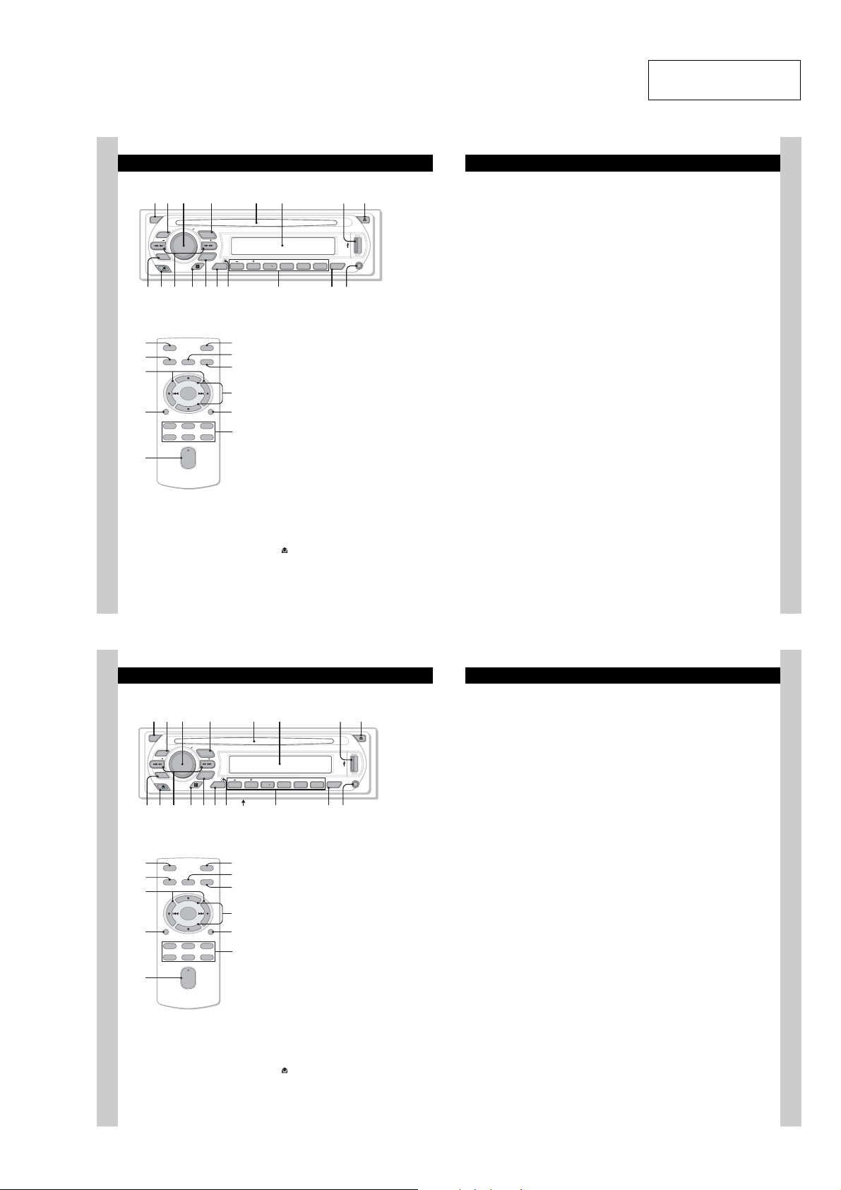
• LOCATION OF CONTROLS
1 2
4 5 863
7
1 2 4 5 863
qaq
q;9 qsqfq
7
q
q
q
q
• CDX-GT41UW/GT410U
Location of controls and basic operations
Main unit
OFF
Card remote commander
RM-X151
1
4
ql
qf
w;
PUSH SELECT
EQ3
SEEK
CAT
BTM
qa qdq;9 qs qfqg
OFF
SEL
SOURCE
+
–
DSPL
132
465
+
VOL
–
SOURCE
SEEK
MODE
DIM REP SHUF
GP/ALBM
123456
DSPL
wa
ATT
ws
MODE
qd
wd
SCRL
qj
wf
Refer to the pages listed for details. The
corresponding buttons on the card remote
commander control the same functions as those
on the unit.
A OFF button
B EQ3 (equalizer) button 10
C Volume control dial/select button 10
D SOURCE button
E Disc slot
F Display window
G USB terminal 9
H Z (eject) button
I BTM/CAT*
J (front panel release) button 5
PAUSE
AUX
SCRL
CDX-GT410U
CDX-GT41UW
qjqh
qk
To po we r off; stop the source.
To select an equalizer type (XPLOD,
VOCAL, EDGE, CRUISE, SPACE,
GRAVITY, CUSTOM or OFF).
To ad ju st vo lume (rotate); select setup items
(press and rotate).
To po we r on; change the sour ce (Radio/CD/
1
MD*
/USB/AUX/SAT*2).
Insert the disc (label side up), playback
starts.
To co nnect to the USB device.
To ej e c t the disc.
2
button 8
To st art t he BTM function (press and hold).
CDX-GT41UW/GT410U/GT460U/GT460US
SECTION 1
GENERAL
K SEEK –/+ buttons
1
CD/MD*
/USB*3:
To sk ip tracks (press); skip tracks
continuously (press, then press again within
about 1 second and hold); reverse/fastforward a track (press and hold).
Radio:
To tune in stations automatically (press); find
a station manually (press and hold).
L Receptor for the card remo te
commander
M MODE button 8, 10, 12
To select the radio band (FM/AM); select the
SAT tuner band (mode)*
select the play mode*
N DSPL (display)/DIM (dimmer) butt on
8, 9
To ch ange display items (press); change the
display brightness (press and hol d).
O RESET button (located behind the front
panel) 4
P Number buttons
CD/MD*
(1)/(2): GP*
To s kip albums (press); skip albums
continuously (press and hold) *
(3): REP 8, 10
(4): SHUF 8, 10
(6): PAUS E*
To p ause playback. To cancel, press
again.
Radio:
To re ce ive stored stations (press); store
stations (press and hold).
Q SCRL (scroll) button 8, 9
To sc ro ll th e display item.
R AUX input jack 11
To co nnect a portable audio device.
1
/USB*3:
5
.
6
/ALBM*7 –/+
9
2
; select the unit*4;
8
.
This section is extracted
from instruction manual.
The following buttons on the card remote
commander have also different buttons/functions
from the unit. Remove the insulation film before
use (page 4).
ql < (.)/, (>) buttons
To control CD/radio/MD/USB, the same as
(SEEK) –/+ on the unit.
w; VOL (volume) +/– button
To adjust volume.
wa AT T (attenuate) button
To att e nuate the sound. To cancel, press
again.
ws SEL (select) button
The same as the select button on the unit.
wd M (+)/m (–) buttons
To control CD, the same as (1)/(2) (GP/
ALBM –/+) on the unit.
wf Number buttons
To r e c e ive stored st at ions (press); store
stations (press and hold).
*1
When an MD changer is co nnected.
*2
When the SAT tuner is connected.
*3
When a USB device is connected.
*4
When a CD/MD changer is connected.
*5
When an ATRAC Audio Device is connected.
*6
When an ATRAC CD is played.
*7
When an MP3/WMA/AAC is played.
*8
If the changer/USB device is connected, the
operation is different, see page 12.
*9
When playing bac k on this unit.
Notes
•
When ejecting/inserting a disc, keep any USB
devices disconnected to avoid damage to the disc.
•
If the unit is turned off and the display disappears, it
cannot be operated with the card remote
commander unless
pressed, or a disc is inserted to activate the unit first.
Tip
For details on how to replace the battery, see
“Replacing the lithium battery of the card remote
commander” on page 15.
About USB cap
When not using the USB terminal (
supplied USB cap to prevent dust or dirt entering.
Keep the USB cap out of the reach of children to
prevent accidental swallowing.
(SOURCE)
on the unit is
G
), use the
6
• CDX-GT460U/GT460US
Location of controls and basic operations
Main unit
OFF
EQ3
SEEK
CAT
BTM
Card remote commander
RM-X151
1
OFF
4
w;
qf
wa
6
SOURCE
DSPL
132
465
SEL
+
–
+
VOL
–
PUSH SELECT
SOURCE
SEEK
MODE
DIM REP SHUF
GP/ALBM
123456
DSPL
d
g
ws
ATT
wd
MODE
qd
wf
SCRL
qk
wg
PAUSE
SCRL
h
j
Refer to the pages listed for details. The
corresponding buttons on the card remote
commander control the same functions as those
on the unit.
A OFF button
To po we r off; stop the source.
B EQ3 (equalizer) button 10
To select an equalizer type (XPLOD,
VOCAL, EDGE, CRUISE, SPACE,
GRAVITY, CUSTOM or OFF).
C Volume control dial/select button 10
To ad ju st vo lume (rotate); select setup items
(press and rotate).
D SOURCE button
To po we r on; change the sour ce (Radio/CD/
MD*
E Disc slot
Insert the disc (label side up), playback
starts.
F Display window
G USB terminal
To co nnect to the USB device. 9
H Z (eject) button
To ej e c t the disc.
I BTM button 8
To st art t he BTM function (press and hold).
J (front panel release) button 5
1
/USB/AUX).
k
CDX-GT460US
CDX-GT460U
l
7
K SEEK –/+ buttons
1
CD/MD*
/USB*2:
To sk ip tracks (press); skip tracks
continuously (press, then press again within
about 1 second and hold); reverse/fastforward a track (press and hold).
Radio:
To tune in stations automatically (press); find
a station manually (press and hold).
L Receptor for the card remo te
AUX
commander
M MODE button 8, 12
To select the radio band (FM/AM); select the
3
unit*
; select the play mode*4.
N DSPL (display)/DIM (dimmer) button
8
To ch ange display item s (press); change the
display brightness (press and hol d).
O RESET button (located behind the front
panel) 4
P Frequency select switch (located on the
bottom of the unit)
See “Frequency select switch” in t he
supplied installation/connections manual.
Q Number buttons
1
CD/MD*
/USB*2:
5
(1)/(2): GP*
(3): REP 8
(4): SHUF 8
(6): PAUS E*
Radio:
To re ce ive stored stations (press); store
stations (press and hold).
R SCRL (scroll) button 8
To sc ro ll th e display item.
S AUX input jack 12
To co nnect a portable audio device.
/ALBM*6 –/+
To s kip albums (press); skip albums
continuously (press and hold) *
8
To p ause playback. To cancel, press
again.
The following buttons on the card remote
commander have also different buttons/functions
from the unit. Remove the insulation film before
use (page 4).
w; < (.)/, (>) buttons
To control CD/radio/MD/USB, the same as
(SEEK) –/+ on the unit.
wa VOL (volume) +/– button
To adjust volume.
ws AT T (attenuate) button
To att e nuate the sound. To cancel, press
again.
wd SEL (select) button
The same as the select button on the unit.
wf M (+)/m (–) buttons
To control CD, the same as (1)/(2) (GP/
ALBM –/+) on the unit.
wg Number buttons
To r e c e ive stored st at ions (press); store
stations (press and hold).
*1
When an MD changer is co nnected.
*2
When a USB device is connected.
*3
When a CD/MD changer is connected.
*4
When an ATRAC Audio Device is connected.
*5
When an ATRAC CD is played.
*6
When an MP3/WMA/AAC is played.
*7
If the changer/USB device is connected, the
operation is different, see page 12.
*8
7
.
When playing bac k on this unit.
Notes
•
When ejecting/inserting a disc, keep any USB
devices disconnected to avoid damage to the disc.
•
If the unit is turned off and the display disappears, it
cannot be operated with the card remote
commander unless
pressed, or a disc is inserted to activate the unit first.
Tip
For details on how to replace the battery, see
“Replacing the lithium battery of the card remote
commander” on page 15.
About USB cap
When not using the USB terminal (
supplied USB cap to prevent dust or dirt entering.
Keep the USB cap out of the reach of children to
prevent accidental swallowing.
(SOURCE)
on the unit is
G
), use the
7
5
Page 6
CDX-GT41UW/GT410U/GT460U/GT460US
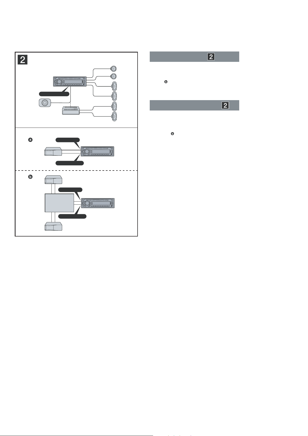
• CONNECTIONS
• CDX-GT41UW/GT410U
A
AUDIO OUT REAR
*
Connection example
Notes
(2-A)
•
Be sure to connect the ground (earth) lead before connecting
the amplifi er.
•
The alarm will only sound if the built-in amplifi er is used.
Tip
(2-B- )
For connecting two or more CD/MD changers, the source
selector XA-C40 (not supplied) is necessary.
Exemple de raccordement
B
*
AUDIO OUT SUB/REAR
BUS AUDIO IN
BUS CONTROL IN
Source selector*
Sélecteur de source*
XA-C40
BUS AUDIO IN
BUS CONTROL IN
*
not supplied
non fourni
Remarques
•
•
Conseil
Dans le cas du raccordement de deux changeurs de CD/MD ou
plus, le sélecteur de source XA-C40 (non fourni) est requis.
(2-A)
Raccordez d’abord le câble de mise à la masse avant de
raccorder l’amplifi cateur.
L’alarme est émise uniquement lorsque l’amplifi cateur intégré
est utilisé.
(2
-B-
)
6
Page 7
CDX-GT41UW/GT410U/GT460U/GT460US
L
R
BUS AUDIO IN
AUDIO OUT
REAR
*
2
BUS
CONTROL IN
2
4
5
1
3
AUDIO OUT
REAR/SUB
BUS
IN
AMP REM
Max. supply current 0.3 A
Courant max. fourni 0,3 A
Fuse (10 A)
Fusible (10 A)
Blue/white striped
Rayé bleu/blanc
ANT REM
Red
Rouge
Yellow
Jaune
Black
Noir
Blue
Bleu
White
Blanc
Green
Vert
Purple
Violet
White/black striped
Rayé blanc/noir
Gray/black striped
Rayé gris/noir
Green/black striped
Rayé vert/noir
Gray
Gris
Left
Gauche
Right
Droit
Left
Gauche
Right
Droit
*
1
RCA pin cord (not supplied)
*
2
AUDIO OUT can be switched SUB or
REAR. For details, see the supplied
Operating Instructions.
*
1
Cordon à broche RCA (non fourni)
*
2
AUDIO OUT peut être commuté sur SUB
ou REAR. Pour obtenir plus de détails,
reportez-vous au mode d’emploi fourni.
Purple/black striped
Rayé volet/noir
*
1
Source selector
(not supplied)
Sélecteur de source
(non fourni)
XA-C40
Supplied with the CD/MD changer
Fourni avec le changeur de CD/MD
Max. supply current 0.1 A
Courant max. fourni 0,1 A
from car antenna (aerial)
à partir de l’antenne
du véhicule
Supplied with XA-C40
Fourni avec le XA-C40
2
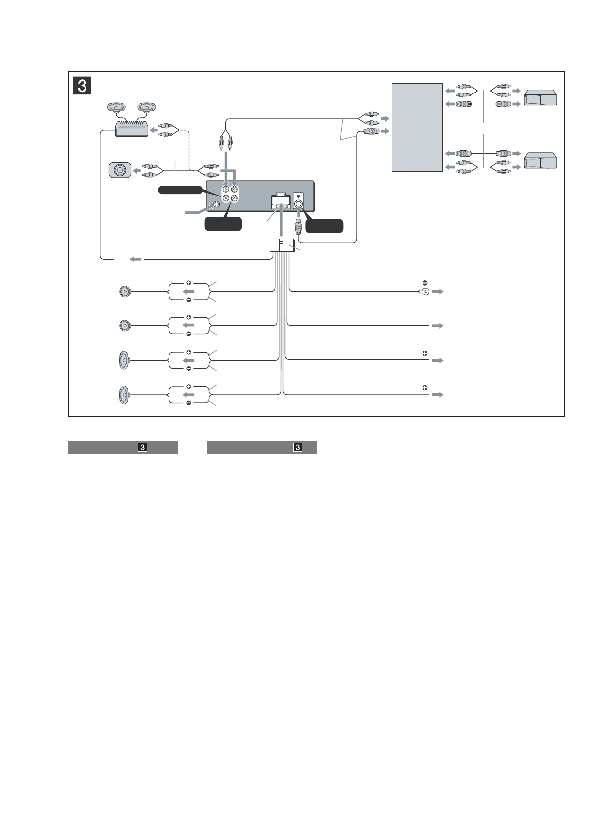
Connection diagram
1 To a metal surface of the car
2 To the power antenna (aerial) control lead or
3 To AMP REMOTE IN of an optional power
4 To the +12 V power terminal which is
5 To the +12 V power terminal which is
Notes on the control and power supply leads
•
The power antenna (aerial) control lead (blue) supplies +12 V
DC when you turn on the tuner.
•
When your car has built-in FM/AM antenna (aerial) in the rear/
side glass, connect the power antenna (aerial) control lead
(blue) or the accessory power supply lead (red) to the power
terminal of the existing antenna (aerial) booster. For details,
consult your dealer.
•
A power antenna (aerial) without a relay box cannot be used
with this unit.
Memory hold connection
When the yellow power supply lead is connected, power will
always be supplied to the memory circuit even when the ignition
switch is turned off.
Notes on speaker connection
•
Before connecting the speakers, turn the unit off.
•
Use speakers with an impedance of 4 to 8 ohms, and with
adequate power handling capacities to avoid its damage.
•
Do not connect the speaker terminals to the car chassis, or
connect the terminals of the right speakers with those of the
left speaker.
•
Do not connect the ground (earth) lead of this unit to the
negative (–) terminal of the speaker.
•
Do not attempt to connect the speakers in parallel.
•
Connect only passive speakers. Connecting active speakers
(with built-in amplifi ers) to the speaker terminals may damage
the unit.
•
To avoid a malfunction, do not use the built-in speaker leads
installed in your car if the unit shares a common negative (–)
lead for the right and left speakers.
•
Do not connect the unit’s speaker leads to each other.
Note on connection
If speaker and amplifi er are not connected correctly, “FAILURE”
appears in the display. In this case, make sure the speaker and
amplifi er are connected correctly.
First connect the black ground (earth) lead, then connect the
yellow and red power supply leads.
power supply lead of antenna (aerial) booster
Notes
•
It is not necessary to connect this lead if there is no power
antenna (aerial) or antenna (aerial) booster, or with a
manually-operated telescopic antenna (aerial).
•
When your car has a built-in FM/AM antenna (aerial) in
the rear/side glass, see “Notes on the control and power
supply leads.”
amplifi er
This connection is only for amplifi ers. Connecting any other
system may damage the unit.
energized in the accessory position of the
ignition switch
Notes
•
If there is no accessory position, connect to the +12 V
power (battery) terminal which is energized at all times.
Be sure to connect the black ground (earth) lead to a
metal surface of the car fi rst.
•
When your car has a built-in FM/AM antenna (aerial) in
the rear/side glass, see “Notes on the control and power
supply leads.”
energized at all times
Be sure to connect the black ground (earth) lead to a metal
surface of the car fi rst.
Schéma de raccordement
1 À un point métallique de la voiture
Branchez d’abord le câble de mise à la masse noir et,
ensuite, les câbles d’alimentation jaune et rouge.
2 Au câble de commande d’antenne électrique
ou au câble d’alimentation de l’amplifi cateur
d’antenne
Remarques
•
Il n’est pas nécessaire de raccorder ce câble s’il n’y a pas
d’antenne électrique ni d’amplifi cateur d’antenne, ou avec
une antenne télescopique manuelle.
•
Si votre voiture est équipée d’une antenne FM/AM
intégrée dans la vitre arrière/latérale, voir « Remarques
sur les câbles de commande et d’alimentation ».
3 Au niveau de AMP REMOTE IN de
l’amplifi cateur de puissance en option
Ce raccordement s’applique uniquement aux amplifi cateurs.
Le branchement de tout autre système risque
d’endommager l’appareil.
4 À la borne +12 V qui est alimentée quand la
clé de contact est sur la position accessoires
Remarques
•
S’il n’y a pas de position accessoires, raccordez la borne
d’alimentation (batterie) +12 V qui est alimentée en
permanence.
Raccordez d’abord le câble de mise à la masse noir à un
point métallique du véhicule.
•
Si votre voiture est équipée d’une antenne FM/AM
intégrée dans la vitre arrière/latérale, voir « Remarques
sur les câbles de commande et d’alimentation ».
5 À la borne +12 V qui est alimentée en
permanence
Raccordez d’abord le câble de mise à la masse noir à un
point métallique du véhicule.
Remarques sur les câbles de commande et d’alimentation
•
Le câble de commande d’antenne électrique (bleu) fournit une
alimentation de + 12 V CC lorsque vous mettez la radio sous
tension.
•
Lorsque votre voiture est équipée d’une antenne FM/AM
intégrée dans la vitre arrière/latérale, raccordez le câble de
commande d’antenne (bleu) ou le câble d’alimentation des
accessoires (rouge) à la borne d’alimentation de l’amplifi cateur
d’antenne existant. Pour plus de détails, consultez votre
détaillant.
•
Une antenne électrique sans boîtier de relais ne peut pas être
utilisée avec cet appareil.
Raccordement pour la conservation de la mémoire
Lorsque le câble d’alimentation jaune est raccordé, le circuit
de la mémoire est alimenté en permanence même si la clé de
contact est sur la position d’arrêt.
Remarques sur le raccordement des haut-parleurs
•
Avant de raccorder les haut-parleurs, mettez l’appareil hors
tension.
•
Utilisez des haut-parleurs ayant une impédance de 4 à 8 ohms
avec une capacité électrique adéquate pour éviter de les
endommager.
•
Ne raccordez pas les bornes du système de haut-parleurs au
châssis de la voiture et ne raccordez pas les bornes du hautparleur droit à celles du haut-parleur gauche.
•
Ne raccordez pas le câble de mise à la masse de cet appareil
à la borne négative (–) du haut-parleur.
•
N’essayez pas de raccorder les haut-parleurs en parallèle.
•
Raccordez uniquement des haut-parleurs passifs. Le
raccordement de haut-parleurs actifs (avec amplifi cateurs
intégrés) aux bornes des haut-parleurs peut endommager
l’appareil.
•
Pour éviter tout problème de fonctionnement, n’utilisez pas les
câbles des haut-parleurs intégrés installés dans votre voiture si
l’appareil partage un câble négatif commun (–) pour les hautparleurs droit et gauche.
•
Ne raccordez pas entre eux les cordons des haut-parleurs de
l’appareil.
Remarque sur le raccordement
Si les haut-parleurs ne sont pas raccordés correctement, le
message « FAILURE » s’affi che. Dans ce cas, assurez-vous que
les haut-parleurs sont bien raccordés.
7
Page 8
CDX-GT41UW/GT410U/GT460U/GT460US
• CDX-GT460U/GT460US
A
B
AUDIO OUT REAR
*
AUDIO OUT SUB/REAR
*
BUS AUDIO IN
BUS CONTROL IN
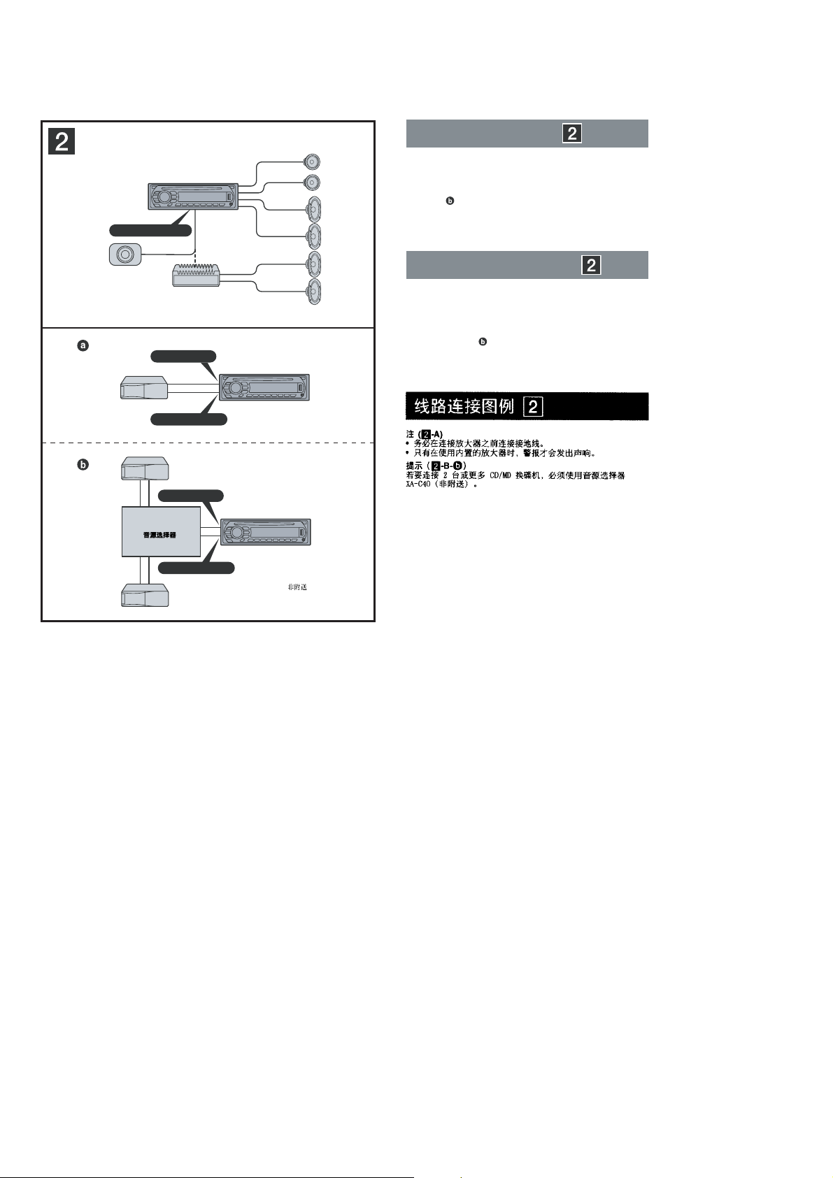
Connection example
Notes
(2-A)
•
Be sure to connect the ground (earth) lead before connecting
the amplifi er.
•
The alarm will only sound if the built-in amplifi er is used.
Tip
(2-B-
For connecting two or more CD/MD changers, the source
selector XA-C40 (not supplied) is necessary.
)
Ejemplo de conexiones
Notas
(2-A)
•
Asegúrese de conectar primero el cable de conexión a masa
antes de realizar la conexión del amplifi cador.
•
La alarma sonará únicamente si se utiliza el amplifi cador
incorporado.
Sugerencia
Si desea conectar dos o más cambiadores de CD/MD,
necesitará el selector de fuente XA-C40 (no suministrado).
(2-B-
)
BUS AUDIO IN
Source selector*
Selector de fuente*
*
XA-C40
BUS CONTROL IN
not supplied
*
no suministrado
8
Page 9
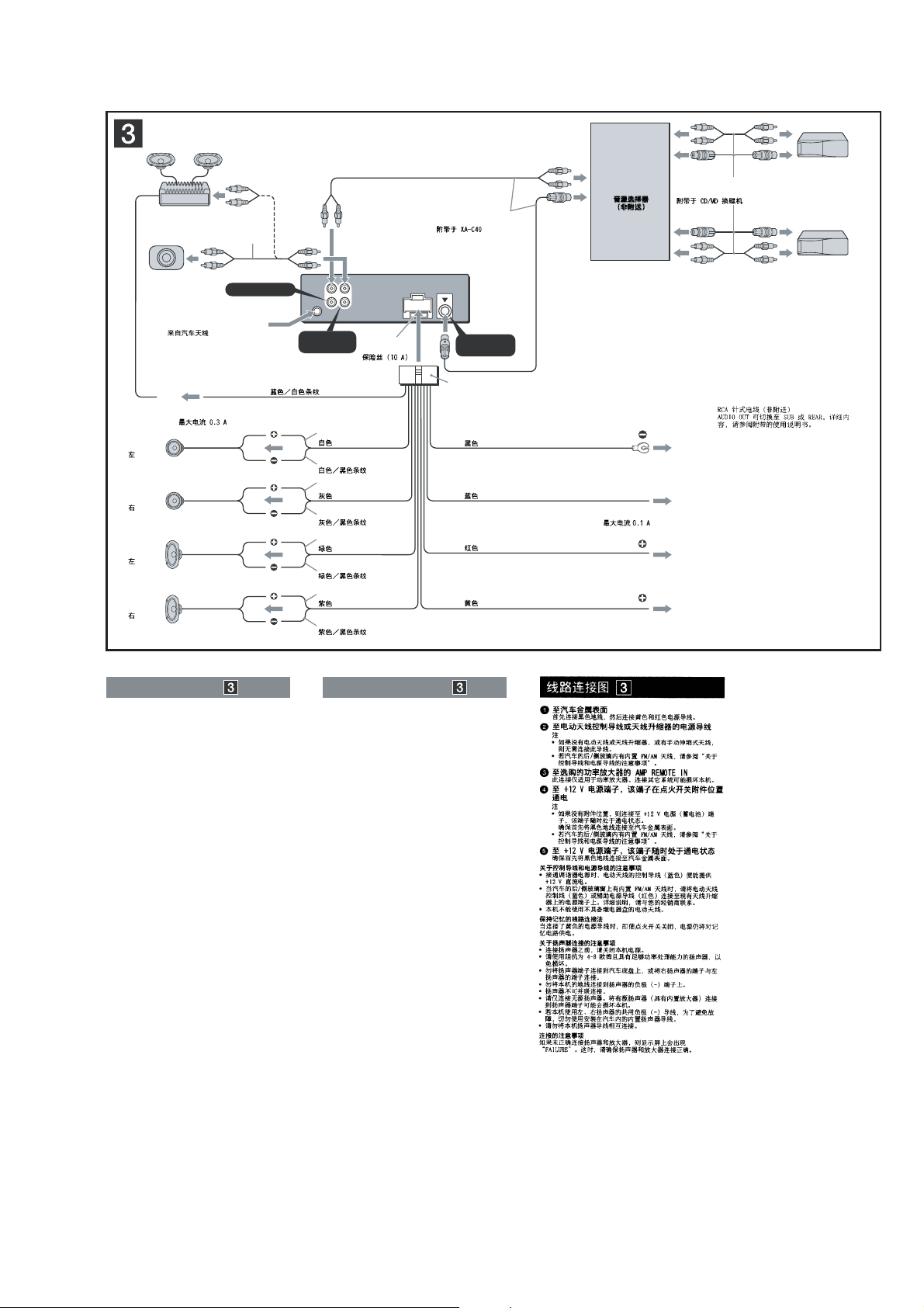
CDX-GT41UW/GT410U/GT460U/GT460US
L
R
BUS AUDIO IN
AUDIO OUT
REAR
*
2
BUS
CONTROL IN
2
4
5
1
3
AUDIO OUT
REAR/SUB
BUS
IN
from car antenna (aerial)
desde la antena del automóvil
*
1
RCA pin cord (not supplied)
*
2
AUDIO OUT can be switched SUB or
REAR. For details, see the supplied
Operating Instructions.
*
1
Cable con terminales RCA
(no suministrado)
*
2
AUDIO OUT (Salida de audio) puede
cambiarse a SUB (Secundaria) o REAR
(Posterior). Para obtener información,
consulte el manual de instrucciones
suministrado.
*
1
*
2
AMP REM
Max. supply current 0.3 A
Corriente máx. de alimentación de 0,3 A
Fuse (10 A)
Fusible (10 A)
Blue/white striped
Con rayas azules y blancas
Red
Rojo
Yellow
Amarillo
White
Blanco
Green
Verde
Purple
Morado
White/black striped
Con rayas blancas y negras
Grey/black striped
Con rayas grises y negras
Green/black striped
Con rayas verdes y negras
Grey
Gris
Left
Izquierdo
Right
Derecho
Left
Izquierdo
Right
Derecho
ANT REM
Black
Negro
Blue
Azul
Max. supply current 0.1 A
Corriente máx. de alimentación de 0,1 A
Purple/black striped
Con rayas moradas y negras
Source selector
(not supplied)
Selector de fuente
(no suministrado)
XA-C40
Supplied with the CD/MD changer
Suministrado con el cambiador de CD/MD
*
1
Supplied with XA-C40
Suministrado con el XA-C40
2
Connection diagram
1 To a metal surface of the car
First connect the black ground (earth) lead, then connect the
yellow and red power supply leads.
2 To the power antenna (aerial) control lead or
power supply lead of antenna (aerial) booster
Notes
•
It is not necessary to connect this lead if there is no power
antenna (aerial) or antenna (aerial) booster, or with a
manually-operated telescopic antenna (aerial).
•
When your car has a built-in FM/AM antenna (aerial) in
the rear/side glass, see “Notes on the control and power
supply leads.”
3 To AMP REMOTE IN of an optional power
amplifi er
This connection is only for amplifi ers. Connecting any other
system may damage the unit.
4 To the +12 V power terminal which is
energized in the accessory position of the
ignition switch
Notes
•
If there is no accessory position, connect to the +12 V
power (battery) terminal which is energized at all times.
Be sure to connect the black ground (earth) lead to a
metal surface of the car fi rst.
•
When your car has a built-in FM/AM antenna (aerial) in
the rear/side glass, see “Notes on the control and power
supply leads.”
5 To the +12 V power terminal which is
energized at all times
Be sure to connect the black ground (earth) lead to a metal
surface of the car fi rst.
Notes on the control and power supply leads
•
The power antenna (aerial) control lead (blue) supplies +12 V
DC when you turn on the tuner.
•
When your car has built-in FM/AM antenna (aerial) in the rear/
side glass, connect the power antenna (aerial) control lead
(blue) or the accessory power supply lead (red) to the power
terminal of the existing antenna (aerial) booster. For details,
consult your dealer.
•
A power antenna (aerial) without a relay box cannot be used
with this unit.
Memory hold connection
When the yellow power supply lead is connected, power will
always be supplied to the memory circuit even when the ignition
switch is turned off.
Notes on speaker connection
•
Before connecting the speakers, turn the unit off.
•
Use speakers with an impedance of 4 to 8 ohms, and with
adequate power handling capacities to avoid its damage.
•
Do not connect the speaker terminals to the car chassis, or
connect the terminals of the right speakers with those of the
left speaker.
•
Do not connect the ground (earth) lead of this unit to the
negative (–) terminal of the speaker.
•
Do not attempt to connect the speakers in parallel.
•
Connect only passive speakers. Connecting active speakers
(with built-in amplifi ers) to the speaker terminals may damage
the unit.
•
To avoid a malfunction, do not use the built-in speaker leads
installed in your car if the unit shares a common negative (–)
lead for the right and left speakers.
•
Do not connect the unit’s speaker leads to each other.
Note on connection
If speaker and amplifi er are not connected correctly, “FAILURE”
appears in the display. In this case, make sure the speaker and
amplifi er are connected correctly.
Diagrama de conexión
1 A una superfi cie metálica del automóvil
Conecte primero el cable de conexión a masa negro, y
después los cables amarillo y rojo de fuente de alimentación.
2 Al cable de control de la antena motorizada
o al cable de fuente de alimentación del
amplifi cador de señal de la antena
Notas
•
Si no se dispone de antena motorizada ni de amplifi cador
de antena, o se utiliza una antena telescópica accionada
manualmente, no será necesario conectar este cable.
•
Si el automóvil incorpora una antena de FM/AM en el
cristal trasero o lateral, consulte “Notas sobre los cables
de control y de fuente de alimentación”.
3 A AMP REMOTE IN de un amplifi cador de
potencia opcional
Esta conexión es sólo para amplifi cadores. La conexión de
cualquier otro sistema puede dañar la unidad.
4 Al terminal de alimentación de +12 V que
recibe energía en la posición de accesorio
del interruptor de encendido
Notas
•
Si no hay posición de accesorio, conéctelo al terminal de
alimentación (batería) de +12 V que recibe energía sin
interrupción.
Asegúrese de conectar primero el cable de conexión a
masa negro a una superfi cie metálica del automóvil.
•
Si el automóvil incorpora una antena de FM/AM en el
cristal trasero o lateral, consulte “Notas sobre los cables
de control y de fuente de alimentación”.
5 Al terminal de alimentación de +12 V que
recibe energía sin interrupción
Asegúrese de conectar primero el cable de conexión a masa
negro a una superfi cie metálica del automóvil.
Notas sobre los cables de control y de fuente de
alimentación
•
El cable de control de la antena motorizada (azul) suministrará
cc de + 12 V cuando conecte la alimentación del sintonizador.
•
Si el automóvil dispone de una antena de FM/AM incorporada
en el cristal trasero o lateral, conecte el cable de control de
antena motorizada (azul) o el cable de fuente de alimentación
auxiliar (rojo) al terminal de alimentación del amplifi cador de
antena existente. Para obtener más información, consulte a su
distribuidor.
•
Con esta unidad no es posible utilizar una antena motorizada
sin caja de relé.
Conexión para protección de la memoria
Si conecta el cable de fuente de alimentación amarillo, el circuito
de la memoria recibirá siempre alimentación, aunque apague el
interruptor de encendido.
Notas sobre la conexión de los altavoces
•
Antes de conectar los altavoces, desconecte la alimentación
de la unidad.
•
Utilice altavoces con una impedancia de 4 a 8 Ω con la
capacidad de potencia adecuada para evitar que se dañen.
•
No conecte los terminales de altavoz al chasis del automóvil,
ni conecte los terminales del altavoz derecho con los del
izquierdo.
•
No conecte el cable de conexión a masa de esta unidad al
terminal negativo (–) del altavoz.
•
No intente conectar los altavoces en paralelo.
•
Conecte solamente altavoces pasivos. Si conecta altavoces
activos (con amplifi cadores incorporados) a los terminales de
altavoz, puede dañar la unidad.
•
Para evitar fallas de funcionamiento, no utilice los cables de
altavoz incorporados instalados en el automóvil si la unidad
comparte un cable negativo común (–) para los altavoces
derecho e izquierdo.
•
No conecte los cables de altavoz de la unidad entre sí.
Nota sobre la conexión
Si el altavoz no está conectado correctamente, aparecerá
“FAILURE” en la pantalla. Si es así, compruebe la conexión del
altavoz.
9
Page 10
CDX-GT41UW/GT410U/GT460U/GT460US
Ver. 1.2
SECTION 2
DISASSEMBLY
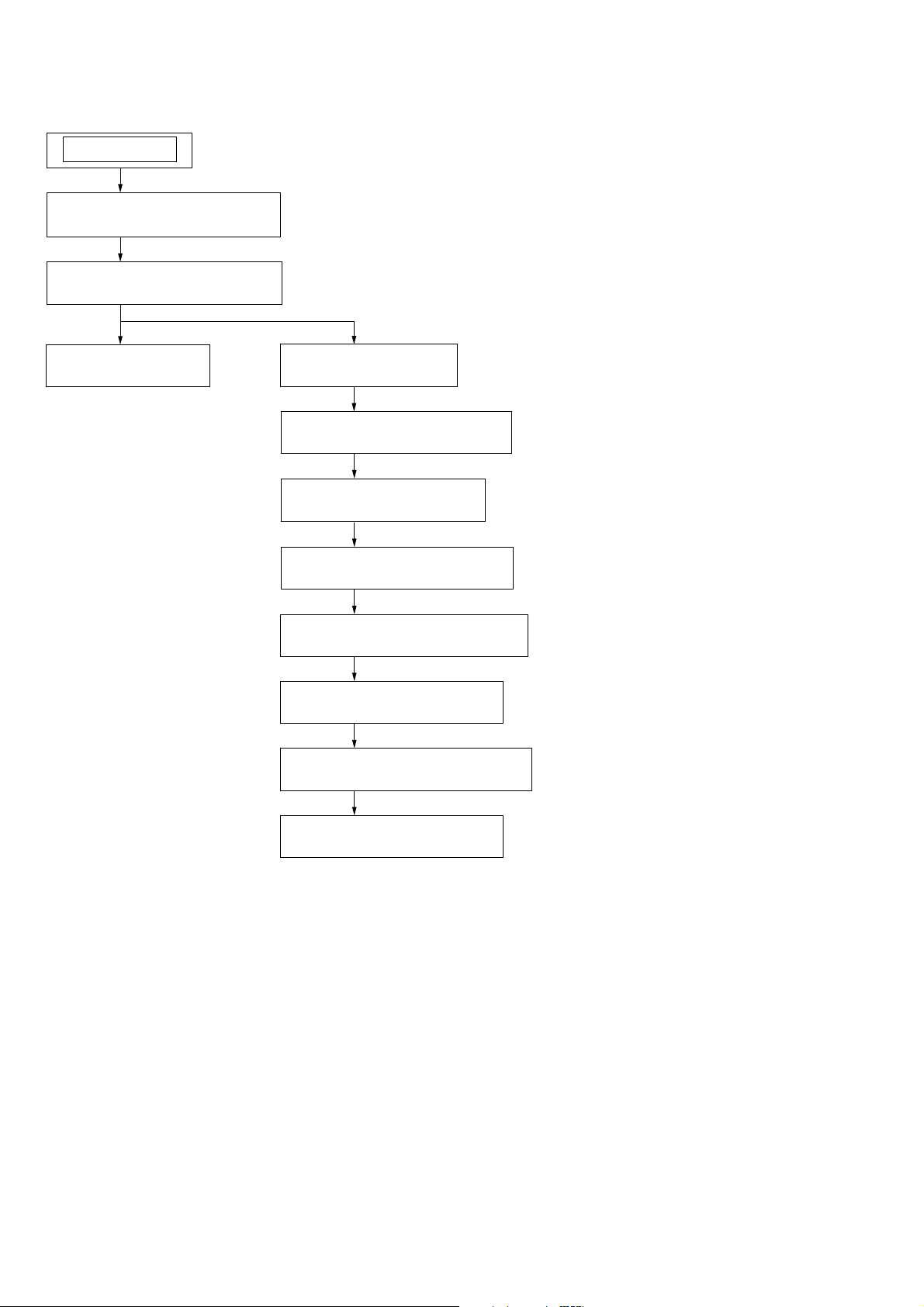
Note: This set can be disassemble according to the following sequence.
SET
2-1. SUB PANEL (FL-U) ASSY
(Page 11)
2-2. CD MECHANISM BLOCK
(Page 11)
2-3. MAIN BOARD
(Page 12)
2-4. SERVO BOARD
(Page 12)
2-5. CHASSIS (T) SUB ASSY
(Page 13)
2-6. ROLLER ARM ASSY
(Page 13)
2-7. CHASSIS (OP) ASSY
(Page 14)
1. CHUCKING ARM SUB ASSY
(SUPPLEMENT-1 Page 1)
2. SLED MOTOR ASSY
(SUPPLEMENT-1 Page 2)
3. OPTICAL PICK-UP SECTION
(SUPPLEMENT-1 Page 3)
10
4. OPTICAL PICK-UP
(SUPPLEMENT-1 Page 3)
Page 11
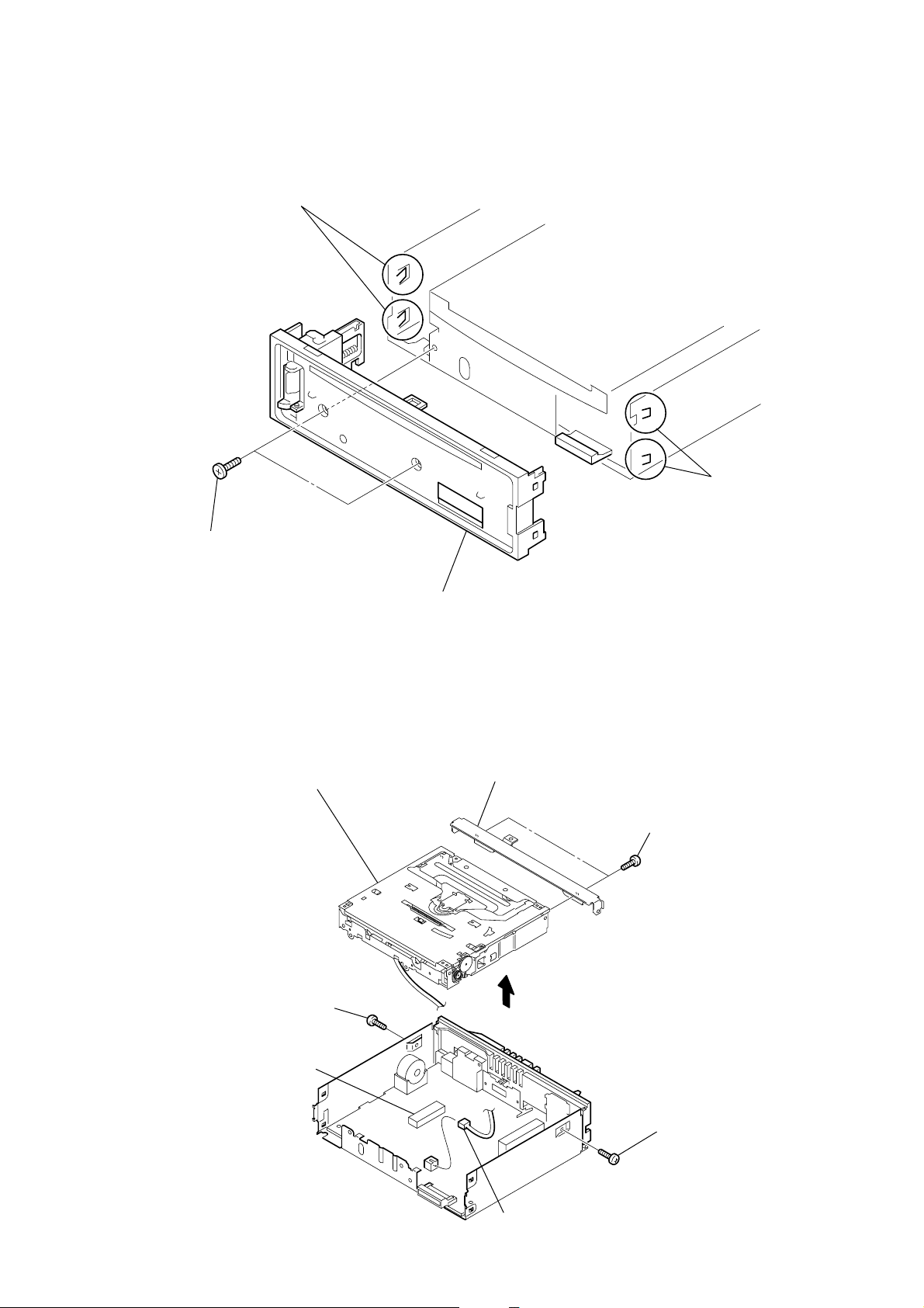
Note: Follow the disassembly procedure in the numerical order given.
s
2-1. SUB PANEL (FL) ASSY
3
two claws
CDX-GT41UW/GT410U/GT460U/GT460US
2
two claw
1
two
screws
(+PTT 2.6
×
6)
2-2. CD MECHANISM BLOCK
8
2
screw
(+PTT 2.6
×
CD mechanism block
6)
4
sub panel (FL-U) assy
7
bracket (CD)
3
6
two
(+PTT 2.6
screws
×
4)
4
CN350
5
CN352 (3P)
1
screw
(+PTT 2.6
×
6)
11
Page 12
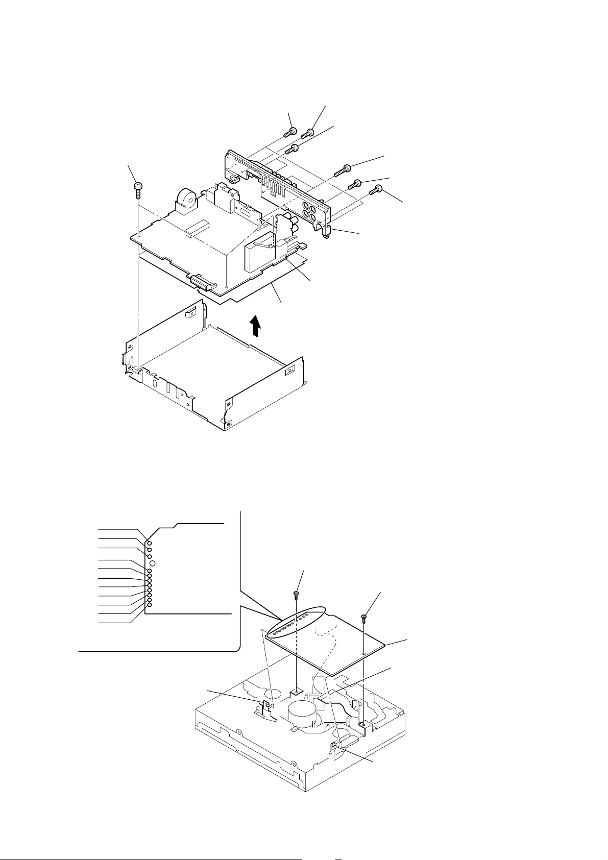
CDX-GT41UW/GT410U/GT460U/GT460US
)
)
2-3. MAIN BOARD
2
two
screws
(+PTT 2.6
1
three
screws
×
(+BTT 2.6
5)
insulating sheet
3
×
8)
4
5
0
MAIN board
two
screws
(+PTT 2.6
two
screws
(+P 2.6
9
×
10)
×
8)
6
7
heat sink
two
screws
(+PTT 2.6
screw
(+P 2.6
8
screw
(+PTT 2.6
×
×
10)
10)
×
10
2-4. SERVO BOARD
WHT
RED
BLK
WHT
RED
BLK
RED
ORG
BLU
YEL
GRY
1
Remove the eleven solders.
SERVO board
claw
2
toothed lock
(M 1.7
×
2.5)
screw
3
claw
toothed lock
(M 1.7
4
optical pick-up (16 core
(CN1)
screw
×
2.5)
5
SERVO board
12
Page 13
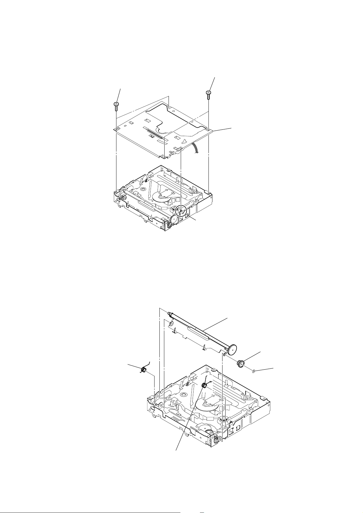
2-5. CHASSIS (T) SUB ASSY
1
two precision
(+P 1.7
×
2.2)
screws
CDX-GT41UW/GT410U/GT460U/GT460US
2
two precision
(+P 1.7
4
screws
×
2.2)
chassis (T) sub assy
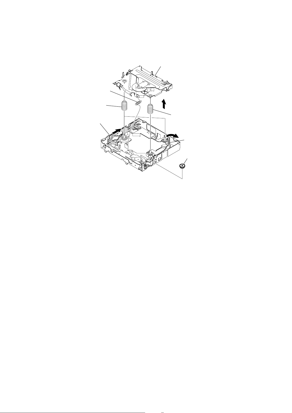
2-6. ROLLER ARM ASSY
1
spring (RAL)
3
claw
5
roller arm assy
4
gear (RA1)
3
washer
2
spring (RAR)
13
Page 14
CDX-GT41UW/GT410U/GT460U/GT460US
)
Ver. 1.2
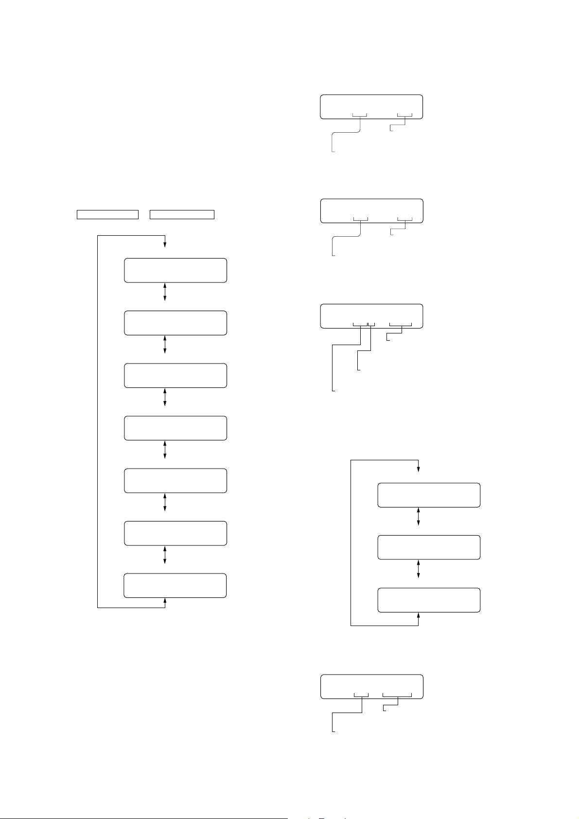
2-7. CHASSIS (OP) ASSY
1
tension spring (KF)
7
coil spring (damper) (natural)
4
slider (R)
6
chassis (OP) assy
5
8
coil spring (damper) (green
3
lever (D)
2
gear (LE1)
14
Page 15
CDX-GT41UW/GT410U/GT460U/GT460US
SECTION 3
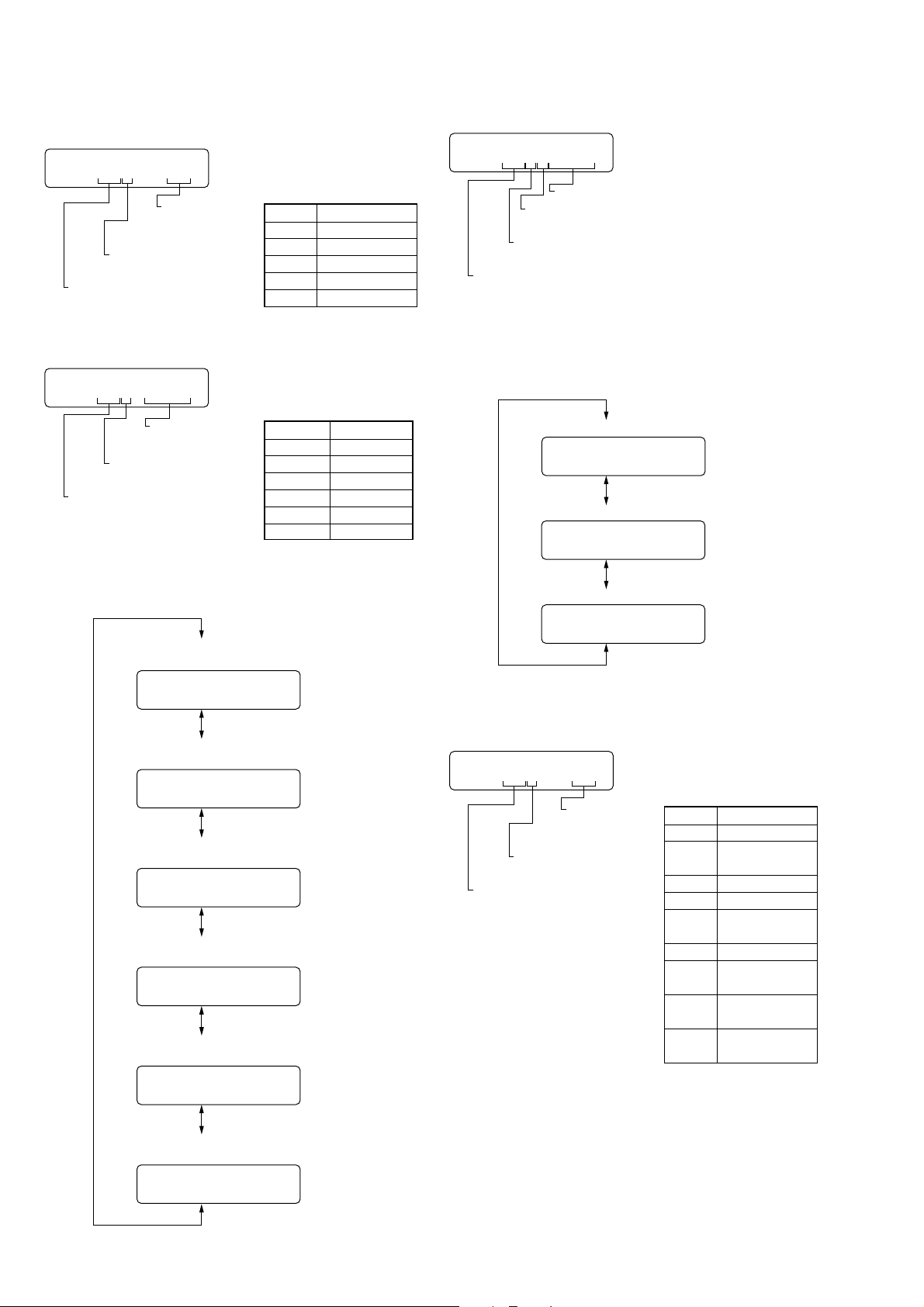
DIAGNOSIS FUNCTION
Description of the Diagnostics function:
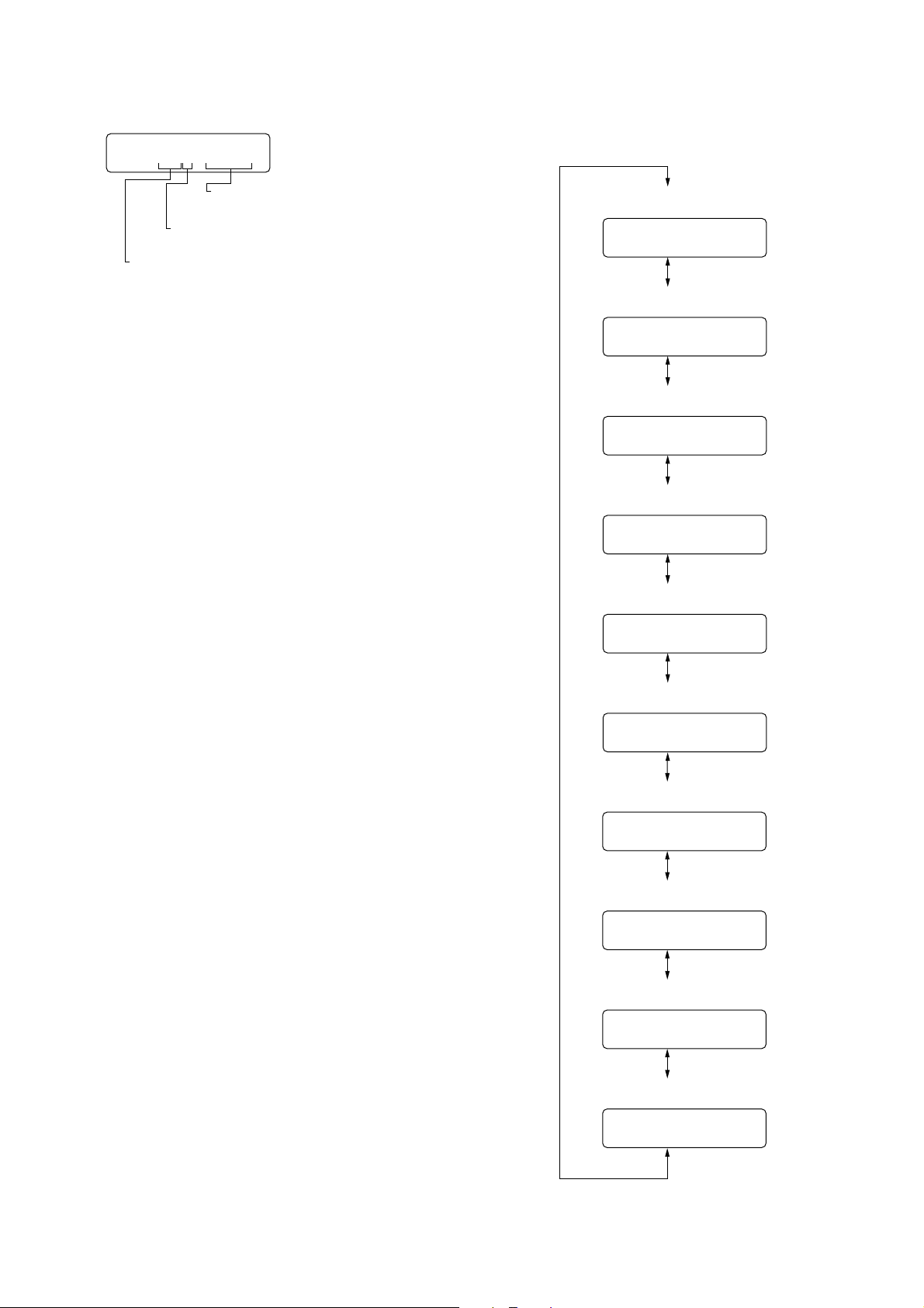
1. Setting the Diag display mode
With the power of f, press the [4] button, [5] button, and [4] button
on the set body or the remote control (for more than 2 seconds)
in turn.
2. Canceling the Diag display mode
During the Diag function mode, press the [OFF] button.
3. Initial display in the Diag display mode.
Just when the Diag mode is entered, “reset count” is displayed.
The display mode is switched by each rotation of
SEEK +/M > or SEEK – /. m keys.
Reset count display
01 XX
Reset count by watchdog timer display
02 XX
Number of connected units display
031 XXX
Operating hours display
04 XXXX
4. Contents of each display mode
4-1. Reset count display mode
01 XX
Reset count
(in hexadecimal format)
Diag code
01: Reset count
4-2. Reset count by watchdog timer display mode
02 XX
Reset count
(in hexadecimal format)
Diag code
02: Number of resets by watchdog timer
4-3. Number of connected units display mode
031 XXX
Show the number of connected units for
CD-C, MD-C and XM respectively from
the rightmost (in hexadecimal format).
Recency of information
1-3: 1 represents the latest.
Diag code
03: Number of connected unit.
The display mode is switched by each rotation of [2/GP/ALBM+] or
[1/GP/ALBM--] keys during the number of connected units display
mode.
CD error information display
051 XX
OFFSET/FAILURE error display
061XXXXX
USB error information display
071 XX
No. of connected units history 1 (latest) display
031 XXX
No. of connected units history 2 display
032 XXX
No. of connected units history 3 display
033 XXX
4-4. Operating hours display mode
04 XXXX
Operating hours
(in hexadecimal format)
Diag code
04: Operating hours
15
Page 16
CDX-GT41UW/GT410U/GT460U/GT460US
4-5. CD error information display mode
4-5-1. Error description
051 XX
Error description
(in hexadecimal
format)
Recency of information
1-3: 1 represents the latest.
Diag code
05: CD error information
4-5-2. Disc type and operating hours
Error information
Indication Description
1X SERVO ERROR
3X LOADING ERROR
4X TRACK JUMP
5X TEXT ERROR
FX MECHA ERROR
051 XXXX
Operating hours
Recency of information
1-3: 1 represents the latest.
Diag code
05: CD error information
The display mode is switched by each rotation of [2/GP/ALBM+] or
[1/GP/ALBM--] keys during the CD error information display mode.
Disc type
Indication Disc type
0 MP3
1 WMA
2 AAC
3ATRAC
8 CD/DA
F UNKNOWN
4-6. OFFSET/FAILURE error display mode
061XXXXX
Operating hours
Error description
(0: OFFSET, 1: FAILURE)
Recency of information
1-3: 1 represents the latest.
Diag code
06: OFFSET/FAILURE
The display mode is switched by each rotation of [2/GP/ALBM+] or
[1/GP/ALBM--] keys during the OFFSET/FAILURE error display
mode.
OFFSET/FAILURE error history 1 (latest) display
061XXXXX
OFFSET/FAILURE error history 2 display
062XXXXX
OFFSET/FAILURE error history 3 display
CD error info history 1 (latest)
Error description plus error details display
051 XX
CD error info history 1 (latest)
Disc type plus operating hours display
051 XXXX
CD error info history 2
Error description plus error details display
052 XX
CD error info history 2
Disc type plus operating hours display
052 XXXX
CD error info history 3
Error description plus error details display
063XXXXX
4-7. USB error information display mode
4-7-1. Error description
071 XX
Error description
(in hexadecimal
format)
Recency of information
1-5: 1 represents the latest.
Diag code
07: USB error information
Error information
Indication Description
15 DEVICE ERROR
17
1E
1F BOOT ERROR
3A
43 READ ERROR
44
FA
FB
FILE ERROR
(NO MUSIC)
POWER ON ERROR
INVALID EJECT
ERROR
INVALID
FORMAT FILE
NOT SUPPORT
DEVICE
HUB NOT
SUPPORT
16
053 XX
CD error info history 3
Disc type plus operating hours display
053 XXXX
Page 17
CDX-GT41UW/GT410U/GT460U/GT460US
4-7-2. Disc type and operating hours The display mode is switched by each rotation of [2/GP/ALBM+] or
[1/GP/ALBM--] keys during the CD error information display mode.
071 XXXX
Operating hours
Recency of information
1-5: 1 represents the latest.
Diag code
07: USB error information
USB error info history 1 (latest)
Error description plus error details display
071 XX
USB error info history 1 (latest)
Disc type plus operating hours display
071XXXXX
USB error info history 2
Error description plus error details display
072 XX
USB error info history 2
Disc type plus operating hours display
072 XXXX
USB error info history 3
Error description plus error details display
073 XX
USB error info history 3
Disc type plus operating hours display
073XXXXX
USB error info history 4
Error description plus error details display
074 XX
USB error info history 4
Disc type plus operating hours display
074 XXXX
USB error info history 5
Error description plus error details display
075 XX
USB error info history 5
Disc type plus operating hours display
075 XXXX
17
Page 18

CDX-GT41UW/GT410U/GT460U/GT460US
MEMO
18
Page 19
SECTION 4
DIAGRAMS
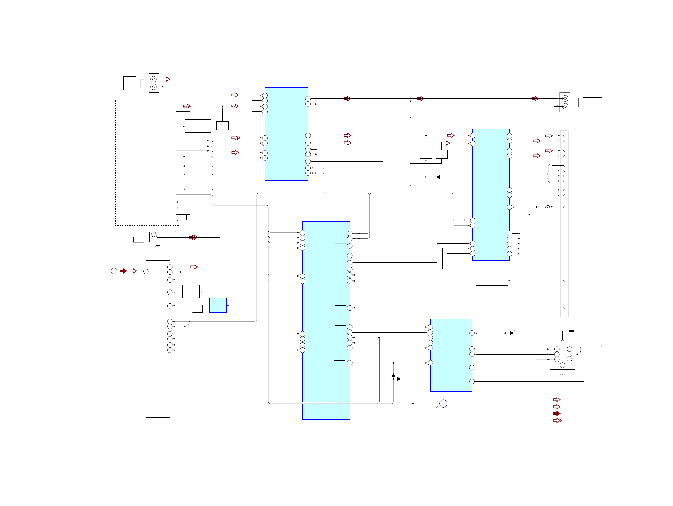
4-1. BLOCK DIAGRAM — MAIN SECTION —
J652 (1/2)
L
BUS
J1
(ANTENNA)
AUDIO
IN
CD
MECHANISM
UNIT
(MG-101U)
(1/2)
J901
AUX
R
1
CDM ON
Z MUTE
WAKE UP
SYS RST
B/U CHECK
BU+3.3V
D+3.3V
TU1
(TUNER UNIT)
L-CH
ANT
R-CH
VCC
VDD+5V
E2PVDD
TU-SCL
TU-SDA
S-METER
TU MUTE
E2P SCL
E2P SDA
BUS-RCH
CD L
CD R
A ATT
CD ON
RXD
TXD
DR+6V
A+3.3V
4
3
10
11
15
13
14
6
7
16
17
MUTE CONTROL
AUX R-CH
TU-RCH
AUDIO+8.3V
TUNER+5V
REG
BU+3.3V
SCL
SDA
CD-RCH
SWITCH
Q411,412
CDMON
ZMUTE
WAKE UP
SYSRST
B/U CHECK
MC TX
MC RX
MECHA+6V
BU+3.3V
SERVO+3.3V
Q3
CDON
AUDIO+8.3V
BU+3.3V
REG
IC681
MUTE
Q401
BUS-RCH
CD-RCH
AUX-RCH
TU-RCH
BU+5V
ELECTRONIC VOLUME
IC401
2
BUS-LCH
1
BUS-RCH
6
CD-LCH
5
CD-RCH
9
AUX-LCH
7
AUX-RCH
4
TU-LCH
3
TU-RCH
CDMON
CDON
ZMUTE
WAKE UP
MC RX
MC TX
SUBOUT-L
SUBOUT-R
OUT-FL
OUT-RL
OUT-FR
OUT-RR
MUTE
SCL
SDA
95
94
61
93
27
28
39
12
25
24
21
22
25
23
26
24
28
29
30
CDMON
CDON
Z MUTE
WAKE UP
MC RX
MC TX
VSM
TUATT
EEP CKO
EEP SIO
R-CH
R-CH(FRONT)
R-CH(REAR)
SCL
SDA
SYSTEM CONTROL
IC501 (1/2)
I2C SCK
I2C SIO
VOLATT
AMPSTB
ACCIN
TESTIN
BUSON
UNISCK
UNISO
SYSRST
ATT
BEEP
DIAG
BUIN
UNISI
CDX-GT41UW/GT410U/GT460U/GT460US
J652 (2/2)
L
AUDIO OUT
REAR/SUB
4
5
6
CN300
10
12
11
16
15
7
8
1
FL+
9
FL–
2
RL+
RL–
4
FR+
FR–
3
RR+
RR–
5
AMP-REM
6
ANT-REM
BATT
7
ACC
TEST
TH400
1
2
3
R
BATT
CNJ400
BUS
CONTROL IN
MUTE
Q432
MUTE
MUTE
Q470
Q440
MUTE CONTROL
SWITCH
Q491,492
SCL
33
SDA
34
9
100
7
8
5
99
97
96
60
54
58
59
88
D353
12
11
10
8
9
13
D491
BUS IN
CLK IN
B/U-C
DATA OUT
DATA IN
RST
BUS INTERFACE
I2C BUS CONTROLLED POWER AMP/
MULTIPLE VOLTAGE REGULATOR
12
IN FL
11
IN RL
BATT
SDA
2
BATT
CLK
SDA
4
SCL
16
BEEP
22
STB
25
DIAG
ACCESSORY CHECK
3
4
6
1
SCL
IC601
DATA I/O
BUS ON
IC300
OUT FL+
OUT FL–
OUT RL+
OUT RL–
AMP REM
ANT REM
AUDIO+B
SERVO3.3V
MECHA6V
PANEL+B
Q702
BATTERY
CHECK
Q605
BU+B
5
3
9
7
29
27
VP
35
BATT
30
AUDIO+8.3V
37
BU+5V
31
SERVO+3.3V
33
MECHA+6V
34
PANEL+B
D602
BATT
R-CH
R-CH
F901
CDX-GT41UW/GT410U/GT460U/GT460US
B/U CHECK
19 19
SYSRST
RESET
DISPLAY
A
SECTION
(Page 20)
RST
2
• R-CH is omitted due to same as L-CH.
• Signal Path
: CD PLAY
: FM
: AM
: AUX
Page 20
CDX-GT41UW/GT410U/GT460U/GT460US
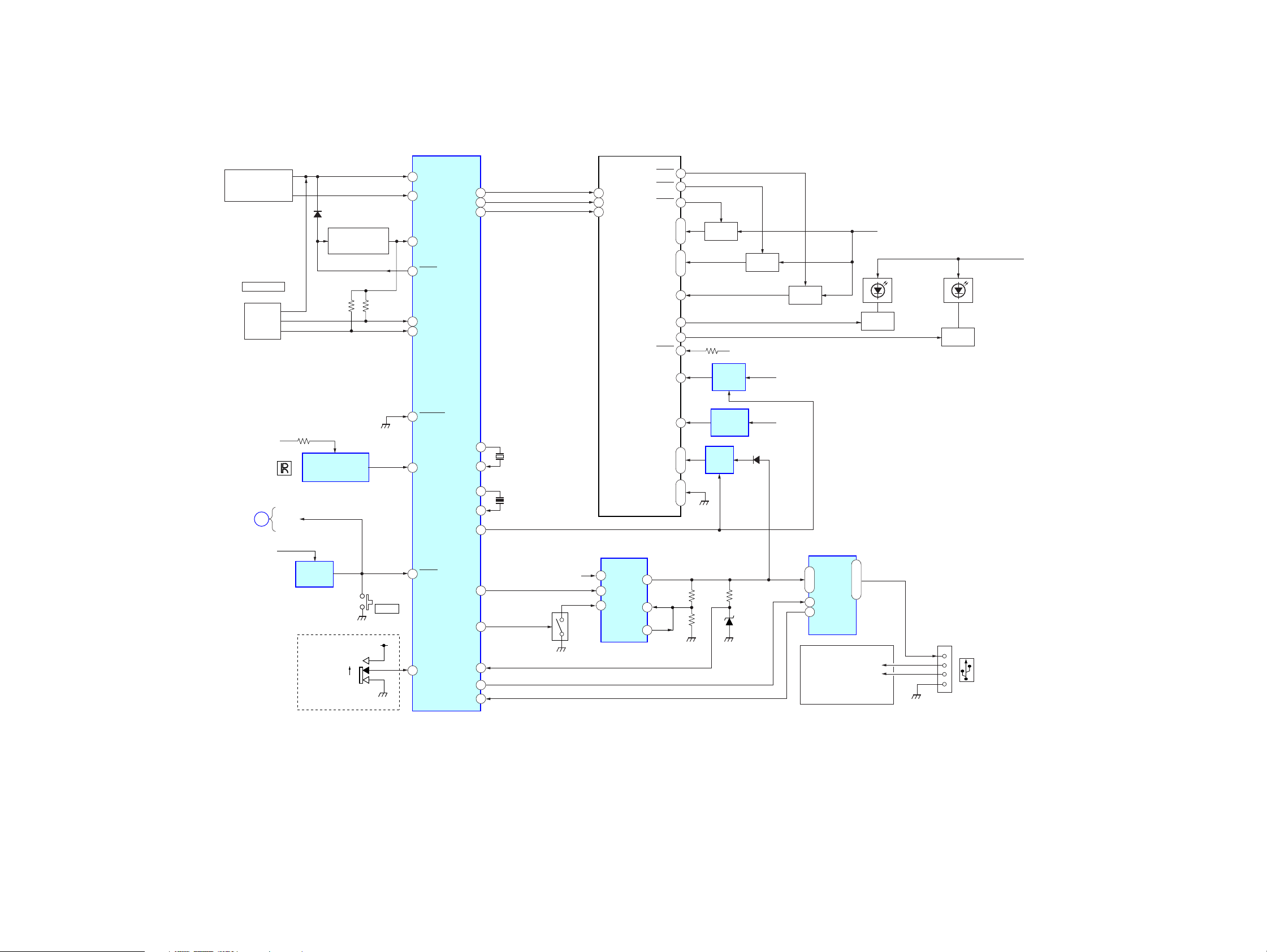
4-2. BLOCK DIAGRAM — DISPLAY SECTION —
KEY MATRIX
LSW901,902
S901–904,906–915
RE901
PUSH SELECT
(VOLUME)
ROTARY
ENCODER
D503
KEY ACKNOWLEDGE
SWITCH
Q664
SYSTEM CONTROL
IC501 (2/2)
KEYIN0
41
KEYIN1
40
KEYACK
52
AD ON
48
RE-IN0
31
RE-IN1
32
FL SO
FL SCK
FL CS
FL901
FLUORESCENT
INDICATOR TUBE
GRID1
20
GRID2
19
20
18
14
DIO
CLK
12
CS
10
GRID3
RESET
19
16
17
FL DRIVE
•
3G
18
6
2G
•
42
1G
41
Q1
40
Q2
39
15
VH
9
Q883
FL +12V
IC801
PANEL+B
REG
FL DRIVE
Q882
BATT
FL DRIVE
Q881
FL VH+12V
LED DRIVE
Q991
LED941–947,
950–957,
961–963,
LSW901,902
LED DRIVE
Q992
LED841–847,
850–857,
861–864,
LSW901,902
PANEL+B
MAIN
SECTION
(Page 19)
PANEL+B
A
BU+3.3V
REMOTE CONTROL
SIGNAL RECEIVER
IC971
RESET
RESET
IC602
S501
FREQUENCY
()
SELECT
GT460U/GT460US
10K
9K
S103
RESET
BU+3.3V
62
64
77
3
NOSESW
SIRCS
RESET
AREASEL2
XOUT
XIN
OSCOUT
OSCIN
FL ON
DD ON
FSW OUT
FSW IN
USB ON
USB OVER
VDD+3.3V
FL+3V
REG
IC802
REG
IC972
D801
VDD(+3.3V)
80
79
83
82
89
90
75
10
92
91
X502
32.768kHz
X501
18.432MHz
SHIFT
CONTROL
SWITCH
Q805
BATT
DC-DC CONVERTER
IC803
1
VIN
SW
EN
7
6
RT
INV
FB
5
1
•
F+
2
44
F–
•
45
2
5
3
D804
PANEL+B
USB CONTROL
IC804
2
•
IN OUT
3
/EN
4
/OC
5
CD
MECHANISM
UNIT
(MG-101U)
(2/2)
6
•
7
•
8
USB D–
USB D+
CN902
CN902
1
2
3
4
CDX-GT41UW/GT410U/GT460U/GT460US
2020
Page 21
CDX-GT41UW/GT410U/GT460U/GT460US
• NOTE FOR PRINTED WIRING BOARDS AND SCHEMATIC DIAGRAMS
THIS NOTE IS COMMON FOR PRINTED WIRING
BOARDS AND SCHEMATIC DIAGRAMS.
(In addition to this, the necessary note is
printed in each block.)
For schematic diagrams.
Note:
• All capacitors are in µF unless otherwise noted. (p: pF)
50 WV or less are not indicated except for electrolytics
and tantalums.
• All resistors are in Ω and 1/
specified.
• f : internal component.
• C : panel designation.
Note:
The components identified by mark 0 or dotted
line with mark 0 are criti-
cal for safety.
Replace only with part
number specified.
• A : B+ Line.
• B : B– Line.
• H : adjustment for repair.
•Voltages and waveforms are dc with respect to ground
under no-signal (detuned) conditions.
no mark : FM
(): AM
<>: CD PLAY
•Voltages are taken with a VOM (Input impedance 10 MΩ).
Voltage variations may be noted due to normal production
tolerances.
•Waveforms are taken with a oscilloscope.
Voltage variations may be noted due to normal production
tolerances.
• Circled numbers refer to waveforms.
• Signal path.
J : CD PLAY
F : FM
f : AM
L : AUX
: Impossible to measure
∗
4
W or less unless otherwise
Note:
Les composants identifiés par
une marque 0 sont critiques
pour la sécurité.
Ne les remplacer que par une
piéce portant le numéro
spécifié.
For printed wiring boards.
Note:
• X : parts extracted from the component side.
• Y : parts extracted from the conductor side.
a
•
• : Pattern from the side which enables seeing.
(The other layers' patterns are not indicated.)
Caution:
Pattern face side: Parts on the pattern face side seen from the
(Side B) pattern face are indicated.
Parts face side: Parts on the parts face side seen from the
(Side A) parts face are indicated.
: Through hole.
C
Q
These are omitted
EB
E
CB
These are omitted
C
BE
These are omitted
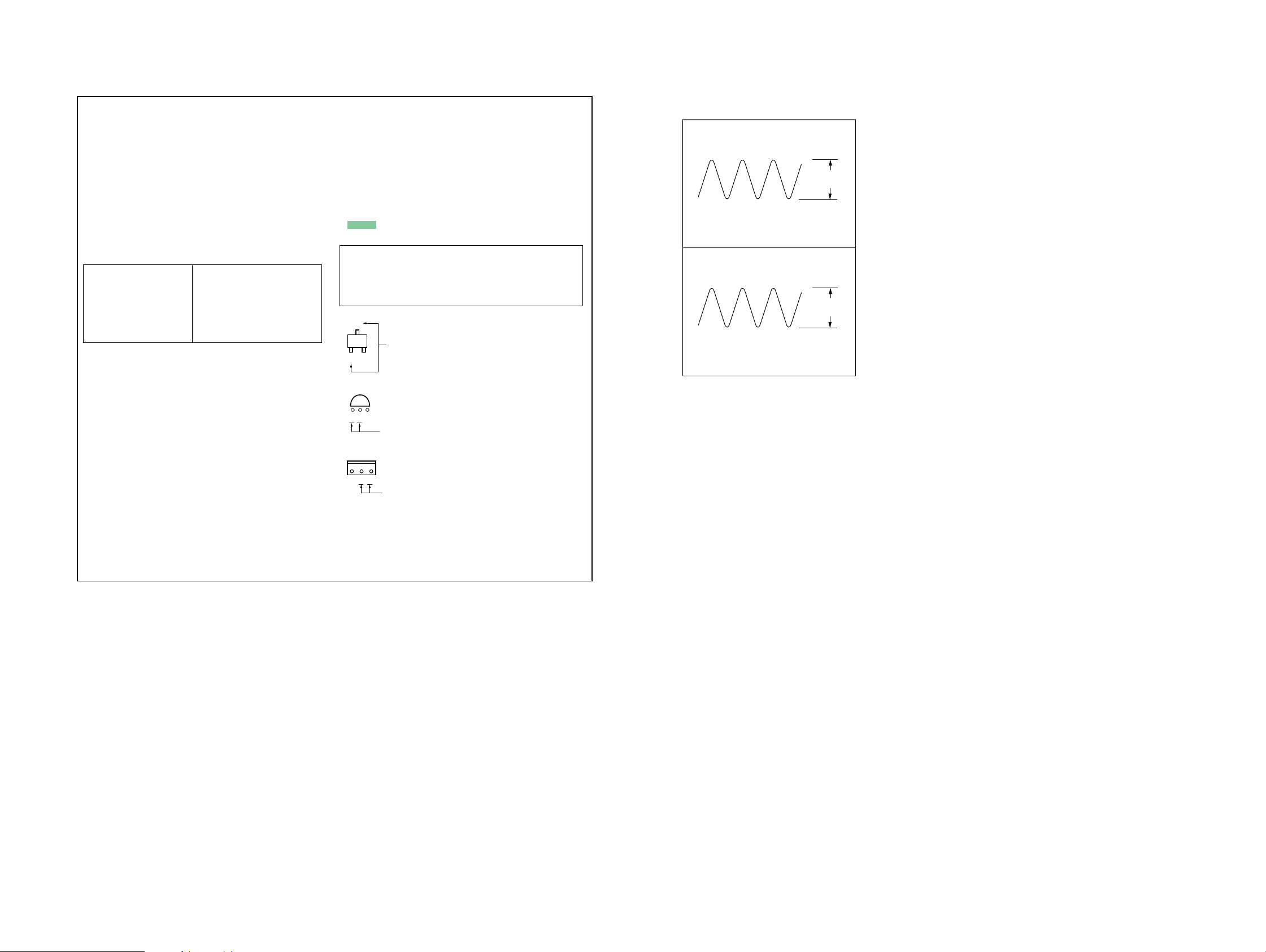
• Waveforms
— MAIN Board —
1
IC501 i; (XOUT)
32.768 kHz
0.2 V/DIV, 20 µsec/DIV
2
IC501 is (OSC IN)
18.432 MHz
µ
0.5 V/DIV, 0.1
sec/DIV
0.8 Vp-p
1 Vp-p
CDX-GT41UW/GT410U/GT460U/GT460US
21 21
Page 22

CDX-GT41UW/GT410U/GT460U/GT460US
4-3. PRINTED WIRING BOARD — MAIN SECTION —
234567891011 12 13 14
J652
BUS
AUDIO IN
LR
-1 -2 -3 -4
C413
C414
R358
R355R356
C366
C365
C905
C362
C361
JC943
38
JW
C15
R2
R9
C3
JC10
C8
R6
R7
R151
R153
L151
C159
D152
D2
C5
L4
C157
R3R4R5
C2
C6
C7
JC28
R558
R155
R154
R150
C158
D156
C153
JC5
C151
R152
R61
JW5
L805
R158
39
JW
JC927
C818
40
JW
R10
9
JW
D109
Q3
C152
LR
R450 R449
C432
Q432
R357
Q452
R354
IC401
R156
R157
133
JW
41
JW
JW27
JW26
JW25
JW137
10
11
12
JW
JW
JW
JC931
JC930
JC929
JC928
D108
JC926
JC924
JW3
JC923
CN370
AUDIO OUT
REAR/SUB
C452
JC11
JW48
JW132
C486
R420
R440
R460
R470
R452
R430
JC4
JW36
JW33
JW32
JW31
JC933
JC932
JW21
JW20
JW19
R595
D113
R596
D153
JW135
JW4
R952
C443
Q420
R448
C441
C421
R421
Q460
R472
Q470
C485
R920
C484
C461
R431
C431
R485
C494
R919
R918
L1
JW35
JW34
JC14
JC12
GT460U/GT460US
S501
FREQUENCY
SELECT
9K
10K
15
13
14
JW
JW
JW
JW134
D112
D103
JC921
R951
JC922
C493
R546
JC934
JC920
A
B
C
D
E
F
G
H
1
J1
(ANTENNA)
TU1
(TUNER UNIT)
JC942
JC941
JW24
R12
R13
JW23
C953
1
I
JW
(CHASSIS)
D151
2
JW
J
(Page 26)
CDX-GT41UW/GT410U/GT460U/GT460US
JW131
JW130
JW44
JW43
JW42
16
JW
D111
D104
C445
C426C423
R523
R520
: Uses unleaded solder.
C424
C444
C317
R301
C318
C303
C463
C473
JC9
C622
L902
L901
JW46
JC8
Q412
Q402
Q401
GT41UW/GT410U
R556
R545
22
JW
C515
R521
R598
D110
1
3
CN352
C319
R302
JC940
R411
R914
90
JW
C504
R505
R597
L804
C309
R491
R915
R510
R522
49
JW
JW53
C306
Q411
R511
R504
C924
JW52
JW54
JW55
R493
JC401
87
JW
C513
C512
R502
C820
C921
R462
C462
C472
R461
R471
C451
17
JW
R442
C471
29
JW
D101
C363
R559
18
JW
D107
R447
C302
R451
C364
28
JW
JC935
D102
Q440
JW47
JW45
JC936
C516
JC911
D106
C623
C308
88
JW
C307
JC939
D491
R961
85
JW
R916
30
JW
C320
C312
C681
140
JW
GT460U
/GT460US
R538
R534
R557
GT460U
/GT460US
C501
C514
C502
R503
C624
R550
R536
R673
7
JW
JC31
56
JW
C491
GT460U
/GT460US
R544
Q491
R404
R537
R567
R671
C305
57
JW
JC938
JC38
JC16
JC29
JC32
R403
R551
JC30
IC300
58
JW
D305
IC681
C683
Q492
R599
82
JW
R507
R552
GT41UW/GT410U
IC501
R565
L818
59
JW
D306
C682
JC1
R531
JW73
JW79
JW72
JW71
JW70
60
JW
129
JW
JW77
Q664
D307
JW78
JC24
C330
C304
66
JW
JW74
JW75
JW76
D503
CNJ400
(BUS CONTROL IN)
YEL
C325
JW50
JW51
C301
C434
61
C454
JW
D309
C313
R592
R672
R570
D310
C509
D308
C314
R561
R517
JC23
R593
C508
R529
128
JW
69
JW
67
JW
JC907
R674
R519
R532
D105
127
JW
C510
62
JW
R540
X502
83
JW
C316
R569
JW80
R927
R526
D502
R553
R533
R913
D312
JW126
81
JW
107
JW
63
JW
R509
C507
R910
R912
68
JW
C315
125
JW
R563
C407
93
JW
JC913
JC914
JC17
X501
124
JW
JC18
L401
C406
JW94
L501
R926
X501
64
JW
C625
JC33
L411
342
C519
JC912
95
JW
L409
IC602
84
JW
D311
R710
R917
1
JC910
R568
R555
C403
L405
C819
C419
C418
91
JW
R923
R600
65
JW
C401
136
JW
R706
R636
JC904
JC905
L402
R402
L410
R401
D353
JW86
S103
S103
RESET
D301
D302
R351
D702
JW99
JW98
JW97
JW96
C412
C402
92
JW
R591
89
JW
R705
R803
C703
R924
R925
JC909
R802
104
JW
CN300
Q702
C702
L403
CN350
JC906
F901
JC902
JC903
JW113
R707
C707
D707
L407
JW117
JW116
JW115
JW114
JW112
R708
C626
JC901
C417
C409
L406
IC804
D303
D304
JC36
R901
R902
R903
C415
JC705
JW123
JW122
JC811
R709
D703
D706
C706
JW103
JW138
JC19
C405
C810
JW120
JW119
CNJ400
C329
321
87
654
JW101
JC22
JW102
C600
C892
C704
JW105
C601
R602
R601
D802
C811
D804
C816
118
JW
C701
D607
D605
D606
JW121
JW139
106
JW
JW100
C890
L803
C815
111
JW
108
JW
YEL
R816
R817
R604
R606
R607
109
JW
C812
C705
R810
R809
IC601
R814
R813
R815
R800
C891
R890
R818
R812
C805
JC21
D603
Q605
R616
JC810
R811
C806
C804
C803
C951
R612
C808
C807
D604
R819
D801
1
7
D901
R603
D602
R611
C809
C814
1
5
IC803
R820
1
IC802
5
IC801
110
JW
L300
R615
L802
Q805
R891
TH400
CN351
C801
C802
1-872-031-
1
4
• Semiconductor Location
Ref. No. Location Ref. No. Location
CN2
CN101
CD
MECHANISM
UNIT
(MG-101U)
D2 E-2
D101 I-4
D102 I-4
D103 I-4
D104 I-4
D105 J-7
D106 I-4
D107 I-4
D108 I-3
D109 I-2
D110 I-4
D111 I-4
D112 I-4
D113 H-3
D151 I-2
D152 I-2
D153 I-3
D156 I-2
D301 C-8
D302 D-8
D303 C-9
D304 D-9
D305 C-6
D306 C-6
D307 C-6
D308 C-6
D309 C-6
D310 C-6
D311 C-7
D312 C-7
11
D353 H-8
D491 E-5
D502 H-7
D503 I-6
D602 D-10
D603 D-10
D604 E-10
D605 D-9
D607 D-9
D702 C-8
D703 C-9
D706 C-9
D707 D-8
D801 F-10
D802 F-9
D804 H-9
D901 B-10
IC300 B-6
IC401 D-3
IC501 G-6
IC601 E-10
IC602 G-7
IC681 D-6
IC801 I-10
IC802 H-10
IC803 G-10
IC804 H-9
Q3 F-2
Q401 F-4
Q402 E-4
Q411 E-5
Q412 E-4
Q420 B-4
Q432 B-3
Q440 B-4
Q452 C-3
Q460 C-4
Q470 C-4
Q491 E-5
Q492 E-5
Q605 D-10
Q664 I-6
Q702 C-8
Q805 G-11
D606 D-9
2222
Page 23
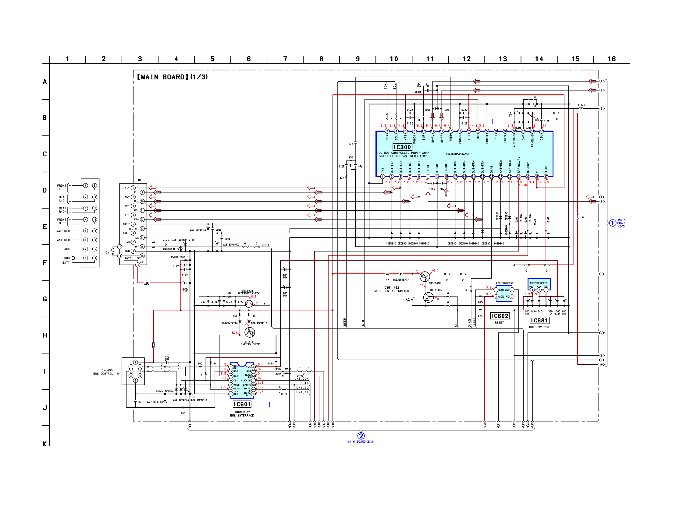
CDX-GT41UW/GT410U/GT460U/GT460US
4-4. SCHEMA TIC DIAGRAM — MAIN SECTION (1/3) —
CN300
D702
D607
C704
C705
C701
F901
L300
R705
R709
D703
• Refer to page 28 for IC Block Diagrams.
D707
C707
C706
D706
R707
R706 R708
C702 C703
R604 R603
D603 D602
JC705
Q702
R710
C625
C626
C317
R301
C319 C318
R302
R491
JC30JC29
D491
C491
C303
C302
C325
C444 C424 C330
JC31
C301
C454 C434
Q491
Q492
IC300
R493 JC8
R599
JC1
C304
R961
R600
R531
IC B/D
301
D
D303D305D306D307D308D309D310D311D312
D302
D304
C306
JC939
JC940
C305 C307
313
315
C
C316
C
JC33 JC32
L902
C308
314
C
IC681IC602
L901
C309
JC12
2
C320
C31
C681C682C683
C622
C623
C624
(Page 24)
CDX-GT41UW/GT410U/GT460U/GT460US
CNJ400
C329
TH400
C600
JC22 R611
JC21
D606
D901
R616
D605 D604
R615
R612
R607
R606
IC601
Q605
IC B/D
C601
R602
R601
JC910
JC19
JC905
JC36
JC909
(Page 25)
23 23
Page 24
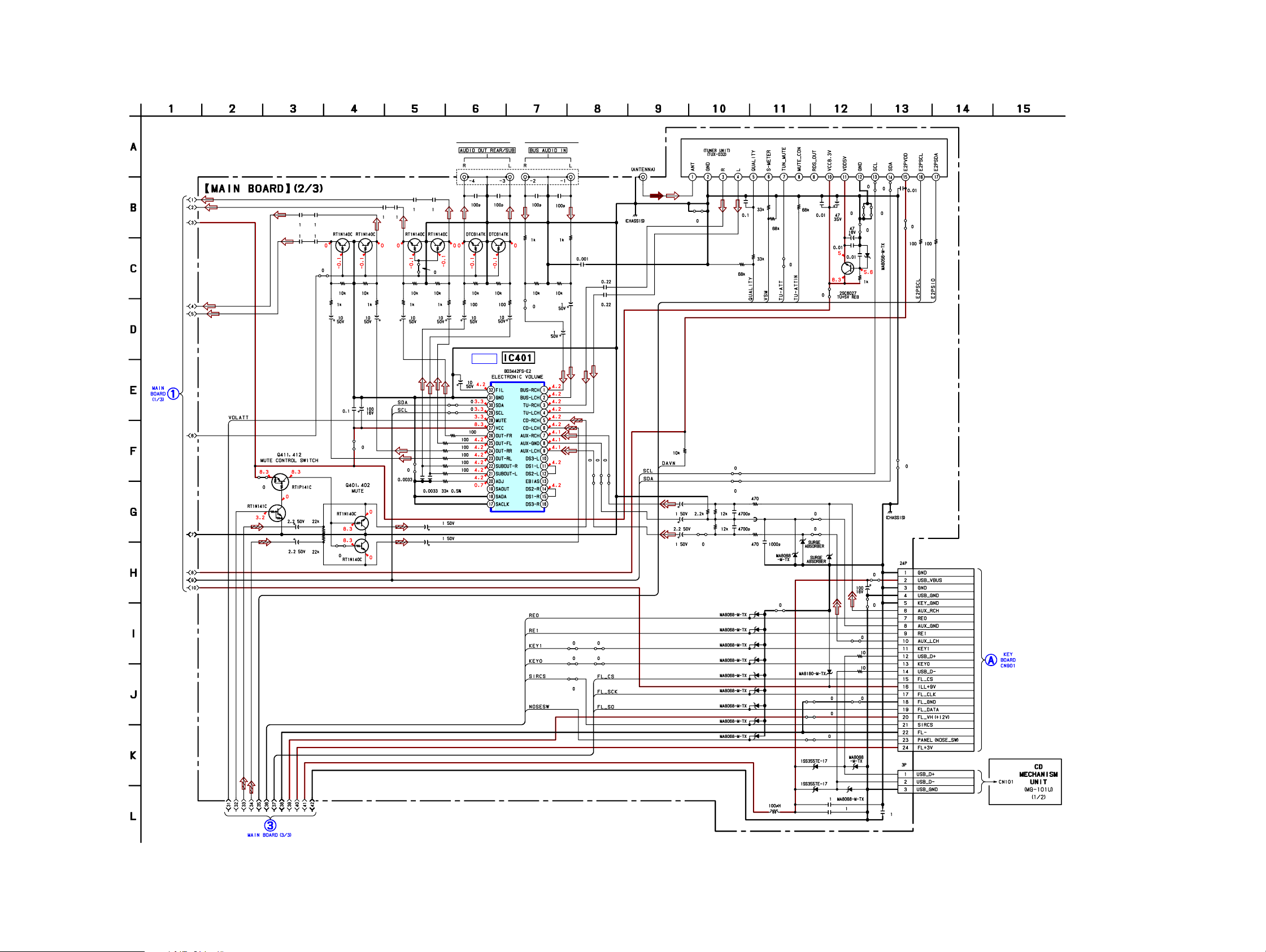
CDX-GT41UW/GT410U/GT460U/GT460US
4-5. SCHEMA TIC DIAGRAM — MAIN SECTION (2/3) —
C445 C443
C426 C423
Q460Q470
R462R472
R461
C461
C485
(Page 23)
C463 C462
C473 C472
JC9
R471
C471
C484
• Refer to page 28 for IC Block Diagrams.
J652
C452 C432 C413
Q440Q420 Q452 Q432
JC11
R447R448 R449 R450
R442R421 R451 R431
C441C421 C451
IC B/D
C486
R918
R919
C431
IC401
C414
R357 R358
R355 R356
R354
C365
C366
C905
C362
C361
TU1
J1
R12
R13
C8
JC943
R4
C15
R2
R3
R9
R5
JC5
C3
L1
JC942 JC941
C2
C5
C6
C7
Q3
JC10
R10
L4
R6 R7
D2
Q411
R411
C407
C406
Q412
R403
R404
JC401
Q402
Q401
R920
C494
R420
R440
R460
R470
C493
C364
C363
R485
R452
R430
R913
R157
R158
R156
JC929JC931
JC928JC930
JC4
R558
C151
C153
C152
JC927
D106
D107
D109
D108
D113
D111
D112
D110
D105
R61
JC28
R151
D156
JC923
R150
D151
D152
D153
JC921 JC922
JC920
R912
D102
D101
C924
C818
JC924
R952
R951
D104
D103
C820
R153R155
C159
L151
R154
C158
C157
R152
JC926
L818
C953
CN370
L805
L804
(Page 27)
CN352
C921
CDX-GT41UW/GT410U/GT460U/GT460US
(Page 25)
2424
Page 25
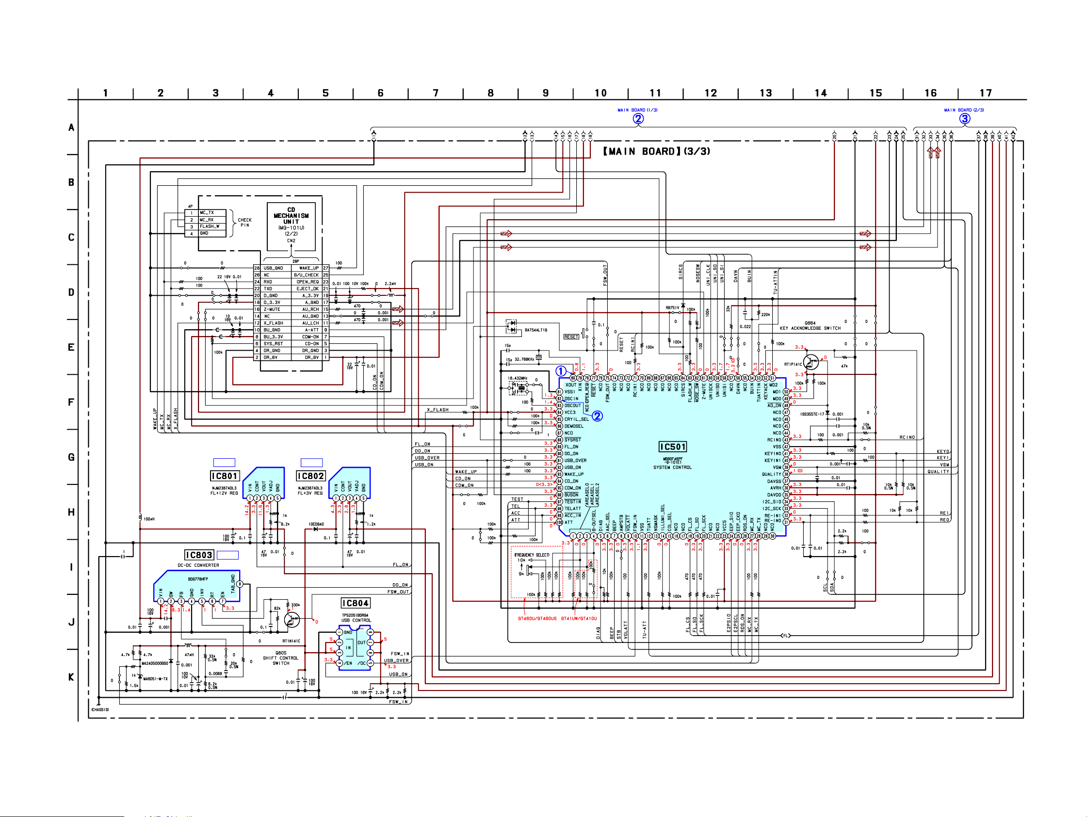
4-6. SCHEMA TIC DIAGRAM — MAIN SECTION (3/3) —
CN351
CDX-GT41UW/GT410U/GT460U/GT460US
• Refer to page 21 for Waveforms.
• Refer to page 29 for IC Block Diagrams.
• Refer to page 30 for IC Pin Description of IC501.
(Page 23) (Page 24)
JC907
C951
C808
R813
R814
L802
R815R800
C809
D802
D801
C891
JC902
JC903
C810
C811
C890
R902
R903
L803
JC901 R901
C417C405
L407
L403
C409
JC906JC904
C415
L405
L406
R351
CN350
IC B/D IC B/D
R809
C801
C802
C804
C803 C806
JC811
R819
C814
Q805
C816
C892
IC803
R816
R817
C812
IC B/D
JC810
R818
R891
R890
R820
R402
L410
R401
C401
C403
IC804
C819
C807
R555
L402 L409
L401
C419
C418
C402
R811
R812R810
R802 R803
L411
R917
R926
R923 R924
JC18
R636
R563
C507
C508
X501
R925
R592
R593
R526
R569
X502
R509
L501
R540
R927
S501
R546
D353
R910
C510
R545
R550
R537
S103
R507
R538
R551
JC38
R552
C519
JC913
R534
JC914
R536
JC14
R672
R557
R674
R544
D502
JC17
R519
IC501
R556
R559 C504
R533
R529
R914
R915
R570
R916
R532
R591
JC912
R553
C509
R598
JC24
R511
R510
R568
R597
R561
Q664
R567R565
D503
R671
C512
C501
C513
C516C515
JC932 JC933
C514
C502
R503
R522
R521
JC934
JC935
R517
R502
JC936
JC938
R673
JC23
R520
R523
JC911
JC16
R505 R504
R596
R595
C412
IC802IC801
D804
C805
C815
CDX-GT41UW/GT410U/GT460U/GT460US
25 25
Page 26
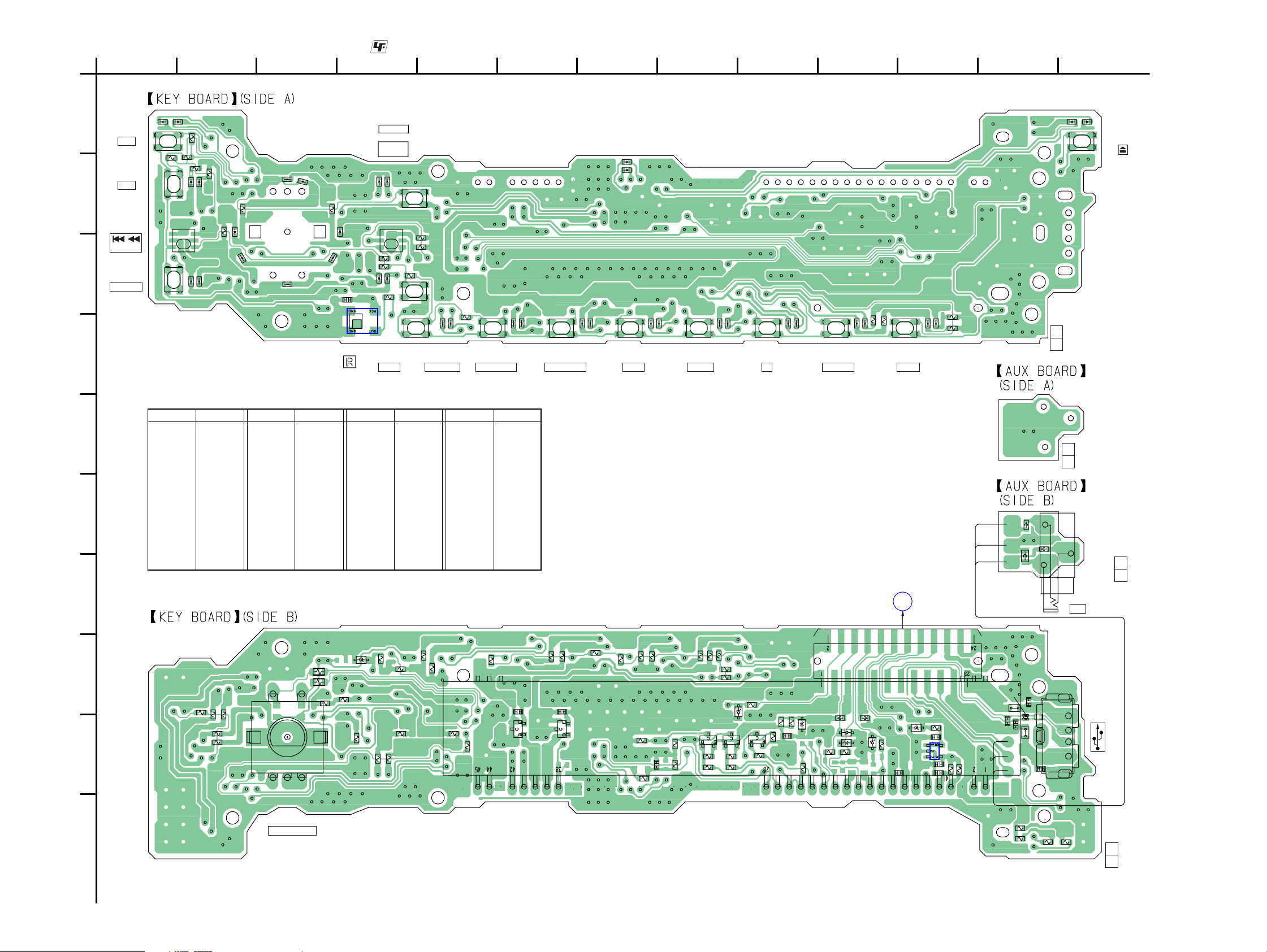
CDX-GT41UW/GT410U/GT460U/GT460US
4-7. PRINTED WIRING BOARD — KEY SECTION —
A
B
C
D
1
LED843,943,
S902
OFF
LED844,944,
S904
EQ3
902
LSW
SEEK–
LED845,945,
S906
BTM/CAT
LED843
S902
R904
S904
LSW902
S906
2345678910111213
LED943
R903
R943
LED944
LED945
R902
LED844
LED845
R843
R862
LED862
R861
LED963
LED861–864,
LED961–963
(RING ILLUM
LED961
LED864
INATION)
LED861
R961
LED863
LED962
C974
IC971
: Uses unleaded solder.
LED846,946,S903
SOURCE
901
LSW
>
M
SEEK+
LED946
LED846
S903
LSW901
R947
R847
R906
R907
IC971
LED847,947,
LED947
R977
S907
MODE
LED847
S907
S908
R908
LED850,950,
DSPL/DIM
LED950
S908
R909
LED850
S909
LED851,951,
S909
1/GP/ALBM–
LED951
LED851
LED852,952,
2/GP/ALBM+
S910
S910
(CD INDICATOR)
LED952
LED852
LED842,942
LED842
LED942
S911
LED853,953,
S911
3/REP
LED953
S912 S913
LED853
LED854,954,
S912
4/SHUF
LED954
LED854
LED855,955,
S913
5
LED955
LED855
LED856,956,
S914
S914
6/PAUSE
LED856
LED956
R854
R954
LED857,957,
S915
S915
SCRL
LED957
LED857
R853
R953
1-872-032-
LED941
11
(11)
LED841
S901
LED841,941,
S901
E
F
G
H
• Semiconductor Location
Ref. No. Location
D903 I-10
D904 I-9
D905 I-10
D906 I-10
D907 I-10
D908 H-9
D971 H-4
IC971 D-4
IC972 I-11
LED841 A-13
LED842 B-7
LED843 A-1
R844
R905
I
Ref. No. Location
LED844 B-2
LED845 C-2
LED846 B-4
LED847 C-4
LED850 D-5
LED851 D-6
LED852 D-7
LED853 D-8
LED854 D-8
LED855 D-9
LED856 D-10
LED857 D-11
LED861 B-3
LED862 B-2
R944
R848
R948
1
5
RE901
4
R921
2
3
Ref. No. Location Ref. No. Location
LED863 B-3
LED864 C-3
LED941 A-13
LED942 B-7
LED943 A-2
LED944 B-2
LED955 D-9
LED956 D-10
LED957 D-11
LED961 B-3
LED962 C-3
LED963 C-2
LED945 C-2
LED946 B-4
LED947 C-4
LED950 D-5
LED951 D-6
LED952 D-7
Q881 I-8
Q882 I-8
Q883 I-9
Q991 I-6
Q992 I-6
LED953 D-7
LED954 D-8
R975
R946
R949
R849
R846
R922
R864
R863
D971
R962
R976
R945
R845
R901
R910
C991
Q991
R950
C992
Q992
R911
R850
R912
FLUORESCENT INDICATOR TUBE
R887
FL901
R981
R951
R851
C977
R888
R982
R884
R881
R952
Q881
R852
R915
D908
R913
Q882
R914
R885
R882
Q883
R883
R971
C979
R886
R984
R983
R889
D904
R995
D907
FB905
D906
R994
(Page 22)
MAIN BOARD CN370
CN901
FB904
D905
R993
11
FB902
D955
LF901
CN902
(11)
1
2
3
4
1-872-033-
J901
AUX
11
(11)
CN902
1-872-033-
ORG
RED
BRN
FB901
FB903
A
RB901
FB906
D903
C982
C976
R978
C975
IC972
C981
R989
R988
BRN
RED
ORG
D953
D951
FB907
C905
J
CDX-GT41UW/GT410U/GT460U/GT460US
RE901
PUSH SELECT
E)
(VOLUM
R841
R942
R941
R842
1-872-032-
11
(11)
2626
Page 27
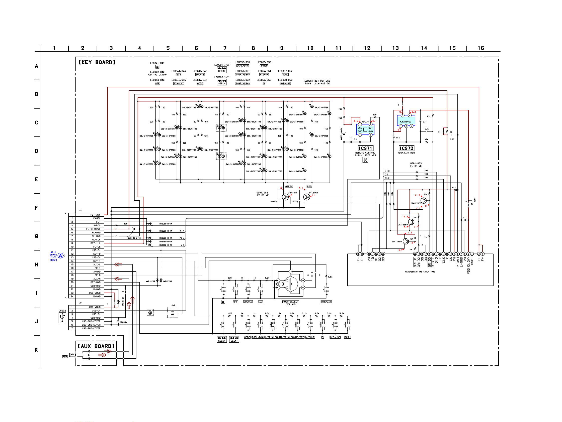
4-8. SCHEMA TIC DIAGRAM — KEY SECTION —
CDX-GT41UW/GT410U/GT460U/GT460US
CN901
R971
FB905
FB904
D904
R841
R941
R842
R942
LED944
D908
D906
D907
D903
D905
LED841
LED842
LED945
LED941
LED942
LED943 LED843
R943
R944
R843
R844
LED946
LED844
LED947
LED845
R945
R946
LED846
R845
LSW901(1/2)
R846
LED847
LSW902(1/2)
R947
R948
R847
R848
LED950
LED951
LED952
R849R949
R951 R851
LED850 LED957
LED953
LED851
R952 R852
R850R950
LED954
LED852
LED955
R953
R853
LED961
LED857
LED853
R954
R854
LED956
LED854
LED855 LED963
C992 C991
LED856
LED962
R961
R962
R887
R888
R889
Q881
C975
R978
Q882
IC972
R881
R884
R885
Q883
R995
R993
R994
R882
C976
R886
R883
R982
C977
R981
R984R983
C979
C982
R988
R989
C981
LED861
LED863
R861
LED862
R862
LED864
Q991Q992
R863
R864
R975
R976
D971
R977
IC971
C974
(Page 24)
CN902
J901
FB902
FB901
FB903
FB906
CDX-GT41UW/GT410U/GT460U/GT460US
FB907
D955
C905
D951 D953
LF901
RB901
R901 R904
R902 R903
S901
S902
S903
R906 R907 R908
LSW902(2/2)
S907
LSW901(2/2)
S904
S908
R909
R910
S909
S910
27 27
R911
S911
R922 R921
R912
S912
R913
S906
S913
R905
R914 R915
S914
FL901RE901
S915
Page 28
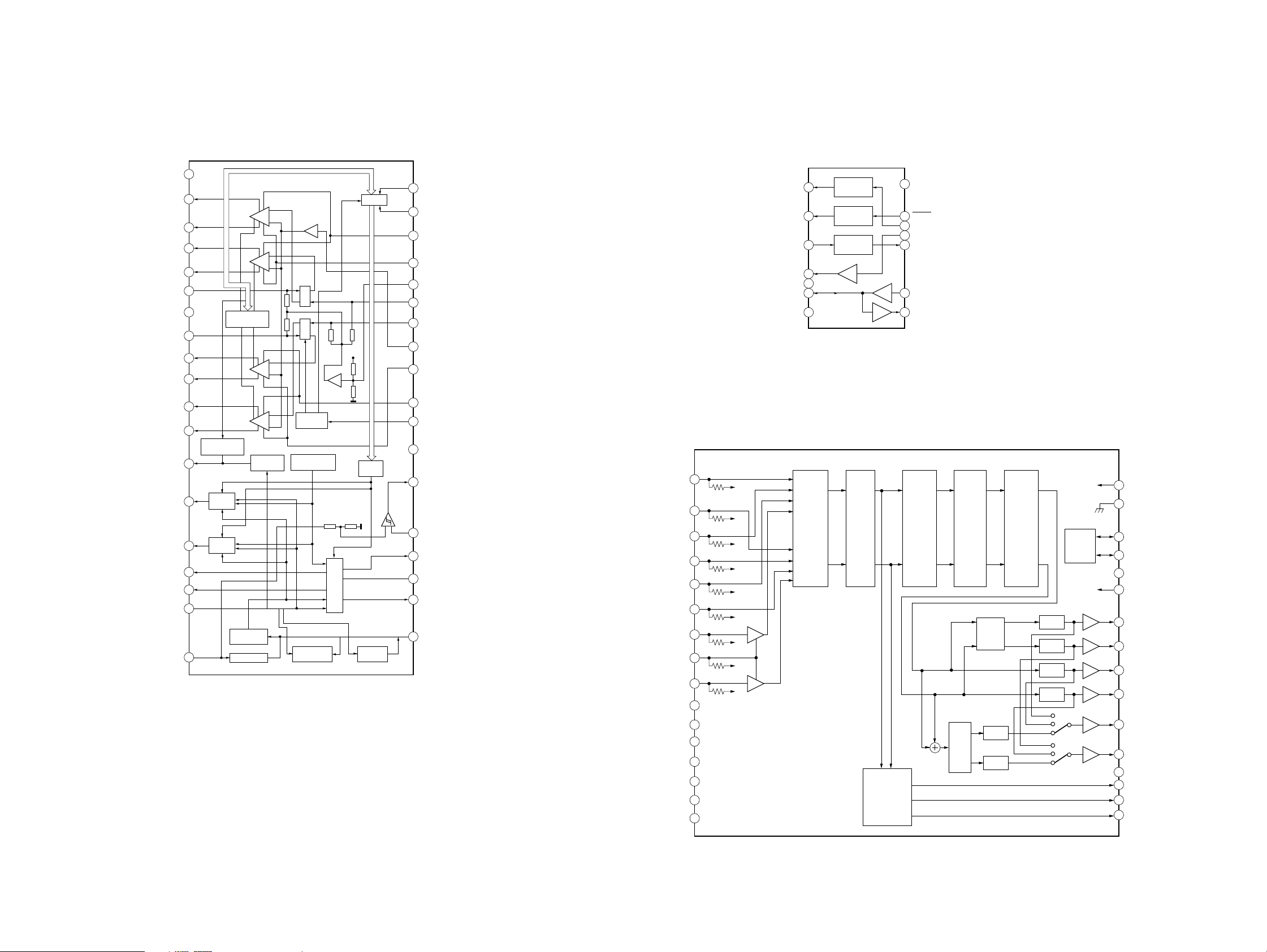
CDX-GT41UW/GT410U/GT460U/GT460US
• IC BLOCK DIAGRAMS
TAB
OUT-FL-
OUT-FL+
OUT-RL-
OUT-RL+
IN-RL
S-GND
IN-RR
OUT-RR+
OUT-RR-
OUT-FR+
OUT-FR-
DIAG
ANT-REM
AMP-REM
SERVO5V
MECH6V
B.UP+B
IC300 TDA8588AJ/N2/R1 (MAIN Board (1/3))
1
VP
3
5
7
9
11
13
15
17
19
21
23
25
27
29
31
33
35
37
PROTECTION/
DIAGNOSTIC
CHIP DETECT/
DIAGNOSTIC
SWITCH
SWITCH
BATTERY
DETECTION
REFERENCE
VOLTAGE
FL
RL
MUTE
MUTE
RR
FR
STANDBY/
MUTE
TEMPERATURE
PROTECTION
LOADDUMP
PROTECTION
VP
ENABLE
REGULATOR
BACK-UP
SWITCHREGULATOR
I2C BUS
LOGIC
2
SDA
4
SCL
6
VP2
8
PGND3
10
SVR
IN-FL
12
14
IN-FR
16
BEEP
18
PGND2
20
VP1
22
STB
24
PGND1
26
RST
CRES
28
30
AUDIO8.3V
32
GND
34
PANEL+B
36
CBU
IC601 BA8271F-E2 (MAIN Board (1/3))
BUS ON
1
2
RST
BATT
3
4
CLK
5
VREF
6
DATA
GND
7 8
IC401 BD3442FS-E2 (MAIN Board (2/3))
BUS-RCH
1
100k
2
BUS-LCH
INPUT
SELECTOR
TU-RCH
TU-LCH
CD-RCH
CD-LCH
AUX-RCH
AUX-GND
AUX-LCH
DS3-L
DS1-L
DS2-L
EBIAS
DS2-R
DS1-R
DS3-R
100k
3
100k
4
100k
5
100k
6
100k
7
250k
8
250k
9
250k
10
11
12
13
14
15
16
BUS ON
SWITCH
RESET
SWITCH
BATTERY
SWITCH
INPUT
GAIN
SPECTRUM
ANALYZER
VCC
14
13
RESET
BUS ON
12
CLK IN
11
BU IN
10
DATA IN
9
DATA OUT
VOLUME1
/MUTE
TREBLE
/BASS
/MIDDLE
LPF
EFFECT
FADER
FADER
VOLUME2
FADER
FADER
FADER
FADER
I2C
BUS
LOGIC
VCC2
32
31
30
29
28
27
26
25
24
23
22
21
20
19
18
17
F2L
GND
SDA
SCL
MUTE
VCCVCC
OUT-FR
OUT-FL
OUT-RR
OUT-RL
SUBOUT-R
SUBOUT-L
ADJ
SAOUT
SADA
SACLK
CDX-GT41UW/GT410U/GT460U/GT460US
2828
Page 29
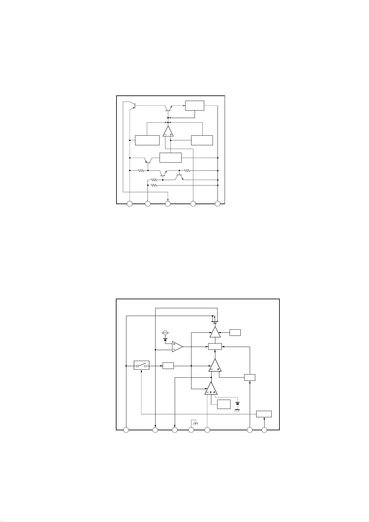
CDX-GT41UW/GT410U/GT460U/GT460US
IC801 NJM2387ADL3 (MAIN Board (3/3))
IC802 NJM2387ADL3 (MAIN Board (3/3))
CURRENT
LIMIT
OVERVOLTAGE
PROTECTION
BANDGAP
REFERENCE
1 2 3 4 5
VIN CONTROL VOUT VADJ GND
THERMAL
PROTECTION
IC803 BD9778HFP (MAIN Board (3/3))
VIN
DRIVER
CURRENT
LIMIT
VREF
1 2 3 4 5
VIN SW PB GND INV
LATCH
ERROR
TSD
RESET
PWM
COMPARATOR
AMP
SOFT
START
VREF
OSC
ON/OFF
6
RT7EN
L:OFF
H:ON
29
Page 30

CDX-GT41UW/GT410U/GT460U/GT460US
• IC PIN DESCRIPTION
IC501 MB90F046PF-G-101E1 (SYSTEM CONTROL) (MAIN BOARD (3/3))
Pin No. Pin Name I/O Pin Description
1 AREASEL0 I Destination setting pin 0
2 AREASEL1 I Destination setting pin 1
3 AREASEL2 I Destination setting pin 2
4B-OUTSEL I Black-out with/without discrimination signal input “H”: Black-out
5 DIAG I Status signal input from power amplifier
6 AAC SEL I AAC play setting signal input
7 BEEP O Beep signal output to power amplifier
8 AMPSTB O Standby signal output to power amplifier
9 VOLATT O Electronic volume attenuate control signal output
10 FSW IN I D/D converter oscillator frequency count signal input
11 VSS — Ground pin
12 TUATT O Tuner mute control signal output
13 NSMASK O Noise mask signal output Not used in this set.
14 ILLUMI SEL I Illumination voltage setting signal input
15 COL SEL I Two colors change setting signal input
16, 17 NCO O Not used. (Open)
18 FL CS O Fluorescent indicator tube chip select signal output
19 FL SO O Fluorescent indicator tube serial data signal output
20 FL SCK O Fluorescent indicator tube serial clock signal output
21, 22 NCO O Not used. (Open)
23 VCC5 — Power supply pin (+3.3 V)
24 EEP SIO I/O EEPROM bus serial data signal input/output
25 EEP CKO O EEPROM bus serial clock signal output
26 RDS ON O RDS (Radio Data System) on signal output Tuner on: “L” Not used in this set.
27 MC RX I Mechanism microcomputer comunication signal input RX
28 MC TX O Mechanism microcomputer comunication signal output TX
29, 30 NCO O Not used. (Open)
31 RE IN0 I Rotary encoder signal input 0
32 RE IN1 I Rotary encoder signal input 1
33 I2C SCK O I2C bus serial clock signal output
34 I2C SIO I/O I2C bus serial data signal input/output
35 DAVDD — A/D converter power supply pin (+3.3 V)
36 AVRH — A/D converter external reference power supply pin (+3.3 V)
37 DAVSS — Ground pin
38 QUALITY I Noise detect signal input
39 VSM I S-meter voltage detect signal input
40 KEYIN1 I Key signal input 1
41 KEYIN0 I Key signal input 0
42 VSS — Ground pin
43 RCIN0 I Rotary commander key signal input Not used in this set.
44 to 47 NCO O Not used. (open)
48 AD ON O A/D converter power supply control signal output
49 MD0 I Operation mode setting pin (Connect to VDD.)
50 MD1 I Operation mode setting pin (Connect to VDD.)
51 MD2 I Operation mode setting pin (Connect to VSS.)
52 KEYACK I Key acknowledgment detect signal input
53 TUATTIN I Tuner mute zero cross detect signal input Not used in this set.
54 BUIN I Back-up power supply detect signal input
30
Page 31
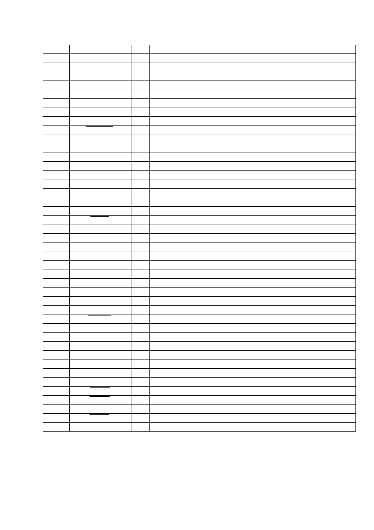
CDX-GT41UW/GT410U/GT460U/GT460US
Pin No. Pin Name I/O Pin Description
55 NCO O Not used. (Open)
56 DAVN I
57 NCO O Not used. (Open)
58 UNISI I SONY bus data signal input
59 UNISO O SONY bus data signal output
60 UNISCK O SONY bus clock signal output
61 Z MUTE I Mute signal input
62 NOSE SW I Front panel attachment detect signal input “L”: With panel, “H”: Without panel
63 FLASH W I
64 SIRCS I Remote control signal input
65 to 70 NCO O Not used. (Open)
71 RC IN1 I Rotary commander shift key signal input Not used in this set.
72 to 74 NCO O Not used. (Open)
75 FSW OUT O
76 NCO O Not used. (Open)
77 RESET I CPU reset signal input
78 NCO (OPEN REQ) O Not used. (Open)
79 XIN I Low speed operation clock signal input (32.768 kHz)
80 XOUT O Low speed operation clock signal output (32.768 kHz)
81 VSS1 — Ground pin
82 OSCIN I High speed operation clock signal input (18.432 MHz)
83 OSCOUT O High speed operation clock signal output (18.432 MHz)
84 VCC3 — Power supply pin (+3.3 V)
85 CYRIL SEL I Cyril correspondence discrimination signal input “L”: No correspondence
86 DEMOSEL I DEMO select signal input “H”: DEMO on, “L”: DEMO off
87 NCO O Not used. (Open)
88 SYSRST O System reset signal output
89 FL ON O Fluorescent indicator tube power on/off control signal output
90 DD ON O D/D converter power on/off control signal output
91 USB OVER I USB overcurrent detection signal input “L”: Overcurrent detection
92 USB ON O USB overcurrent detection IC control signal output “H”: On, “L”: Off
93 WAKE UP O Mechanism microcomputer wake up signal output “H”: Wake up, “L”: Sleep
94 CDON I CD mechanism servo power supply control request signal input
95 CDMON I CD mechanism deck power supply control request signal input
96 BUSON O Bus on signal output
97 TESTIN I Test mode detect signal input
98 TELATT I Telephone attenuate detect signal input
99 ACC IN I Accessory power supply detect signal input
100 ATT O Audio mute control signal output
RDS (Radio Data System) data block synchronized detect signal input
Not used in this set.
Memory mode change signal input Normally “H”: Single chip mode, after reset
“L”: flash write mode
D/D converter oscillator frequency shift control signal output
“L”: 350 kHz, “H”: 415 kHz
31
Page 32
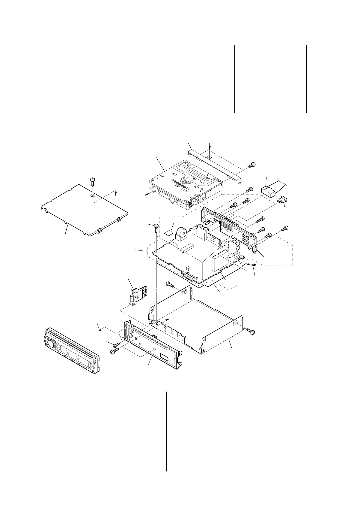
CDX-GT41UW/GT410U/GT460U/GT460US
Ver. 1.2
SECTION 5
EXPLODED VIEWS
NOTE:
• The mechanical parts with no reference
number in the exploded views are not supplied.
• Items marked “*” are not stocked since
they are seldom required for routine service.
Some delay should be anticipated
when ordering these items.
5-1. MAIN SECTION
• -XX and -X mean standardized parts, so
they may have some difference from the
original one.
• Color Indication of Appearance Parts
Example :
KNOB, BALANCE (WHITE) ... (RED)
• Accessories are given in the last of this parts list.
•Abbreviation
CND : Canadian model
IND : Indian model
RR
Parts Color Cabinet’s Color
not supplied
A
The components identified by
mark 0 or dotted line with mark
0 are critical for safety.
Replace only with part number
specified.
Les composants identifiés par une
marque 0 sont critiques pour
la sécurité.
Ne les remplacer que par une piéce
portant le numéro spécifié.
not supplied
#1
not supplied
A
A
MG-101U-188//Q
B
4
5
3
not supplied
#1
B
TU1
not supplied
#4
#2
#3
#5
6
7
#4
#6
#4
not supplied
F901
#3
2
not supplied
#1
#1
1
Ref. No. Part No. Description Remark Ref. No. Part No. Description Remark
1 X-2149-438-1 PANEL (FL-U) ASSY, SUB
2 3-042-244-11 SCREW (T)
3 X-2108-670-1 LOCK ASSY (S)
4 2-050-124-01 SCREW +BTT 2.6X5
5 A-1215-219-A MAIN BOARD, COMPLETE (GT460U/GT460US)
5 A-1215-247-A MAIN BOARD, COMPLETE (GT41UW/GT410U)
6 2-021-848-01 SHEET (TU), GROUND
7 1-833-100-11 CORD (WITH CONNECTOR) (POWER)
(EXCEPT GT460US:IND)
7 1-833-762-11 CONNECTION CORD FOR AUTOMOBILE
(POWER) (for Maruti Suzuki) (GT460US:IND)
F901 1-532-877-11 FUSE (BLADE TYPE) (AUTO FUSE) 10A
TU1 A-3220-961-B TUNER UNIT (TUX-032)
#1 7-685-792-09 SCREW +PTT 2.6X6 (S)
#2 7-685-790-01 SCREW +PTT 2.6X4 (S)
#3 7-685-793-09 SCREW +PTT 2.6X8 (S)
#4 7-685-794-09 SCREW +PTT 2.6X10 (S)
#5 7-685-134-19 SCREW +P 2.6X8 TYPE2 NON-SLIT
#6 7-621-284-40 SCREW +P 2.6X10
32
Page 33
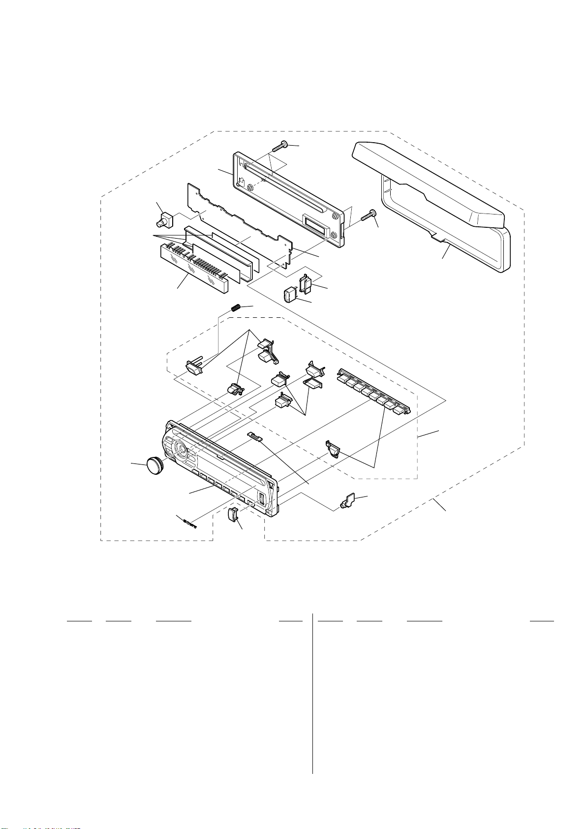
5-2. FRONT PANEL SECTION
RE901
CDX-GT41UW/GT410U/GT460U/GT460US
Ver. 1.1
57
56
not supplied
54
FL901
61
53
55
not supplied
CN902
not supplied
not supplied
not supplied
(KEY board)
59
57
58
52
not supplied
not supplied
(AUX board)
51
60
Ref. No. Part No. Description Remark Ref. No. Part No. Description Remark
51 A-1215-221-A PANEL COMPLETE ASSY, FRONT (GT460US)
51 A-1215-232-A PANEL COMPLETE ASSY, FRONT (GT460U)
51 A-1215-249-A PANEL COMPLETE ASSY, FRONT (GT41UW:US)
51 A-1215-256-A PANEL COMPLETE ASSY, FRONT (GT410U:US)
51 A-1222-410-A PANEL COMPLETE ASSY, FRONT
(GT41UW:CND)
51 A-1222-411-A PANEL COMPLETE ASSY, FRONT
(GT410U:CND)
52 X-2149-756-1 BUTTON ASSY (S) (GT460US)
52 X-2149-757-1 BUTTON ASSY (S) (GT41UW/GT410U/GT460U)
53 X-2149-760-1 PANEL (SV) ASSY, FRONT (GT460US)
53 X-2149-761-1 PANEL (SV) ASSY, FRONT (GT460U)
53 X-2149-762-1 PANEL (SV) ASSY, FRONT (GT41UW)
53 X-2149-763-1 PANEL (SV) ASSY, FRONT (GT410U)
54 X-2149-353-1 KNOB (VOL) (SV) ASSY
55 2-693-599-01 SPRING (RELEASE)
56 2-686-937-02 PANEL (FL-U), BACK
57 3-250-543-21 SCREW (+B P-TITE M2)
58 X-2149-228-2 CASE ASSY (for FRONT PANEL) (EXCEPT US)
59 2-686-941-01 HOLDER (USB)
60 X-2176-322-1 CAP (USB) ASSY
61 3-251-320-01 EMBLEM (NO. 2.5), SONY
CN902 1-820-877-11 CONNECTOR, USB (SOCKET) (USB)
FL901 1-519-909-12 INDICATOR TUBE, FLUORESCENT
RE901 1-479-481-13 ENCODER, ROTARY (PUSH SELECT,VOLUME)
33
Page 34
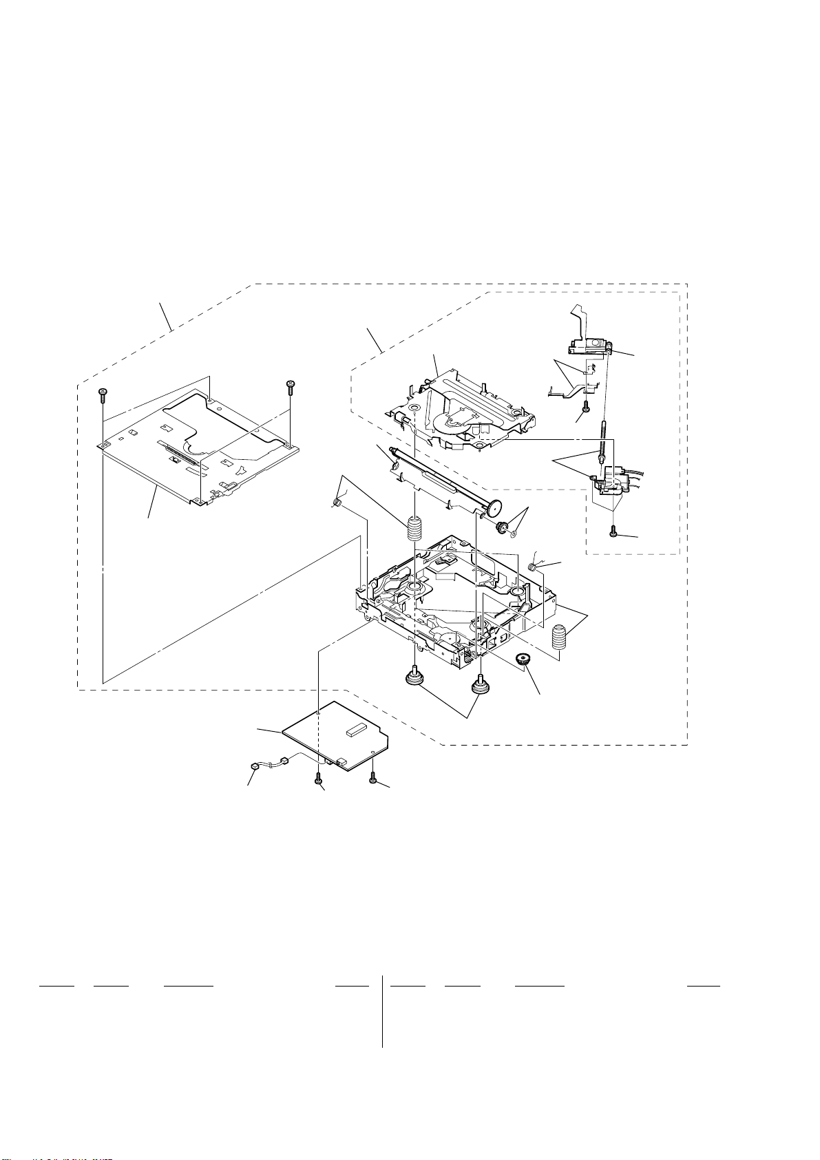
CDX-GT41UW/GT410U/GT460U/GT460US
Ver. 1.2
5-3. CD MECHANISM SECTION
(MG-101U-188//Q)
NOTE: Refer to SUPPLEMENT-1 for disassembly of OPTICAL PICK-UP.
101
102
#7
not supplied
107
#7
not supplied
not supplied
not supplied
not supplied
not supplied
not supplied
not supplied
not supplied
103
105
104
not supplied
not supplied
not supplied
Ref. No. Part No. Description Remark Ref. No. Part No. Description Remark
101 A-1177-168-A MECHANICAL BLOCK ASSY
102 A-1177-169-A DAXEV//Q
0 103 X-2149-672-1 SERVICE ASSY, OP (DAX-25A)
104 2-626-869-01 SCREW (M2X3), SERRATION
106
106
105 3-348-998-31 SCREW (M1.4X2.5), TAPPING, PAN
106 3-352-758-31 SCREW (M1.7X2.5), TOOTHED LOCK
107 A-1206-357-A SERVO BOARD, COMPLETE
#7 7-627-000-08 SCREW, PRECISION +P 1.7X2.2 TYPE3
34
Page 35
CDX-GT41UW/GT410U/GT460U/GT460US
SECTION 6
ELECTRICAL PARTS LIST
NOTE:
• Due to standardization, replacements in
the parts list may be different from the
parts specified in the diagrams or the
components used on the set.
• -XX and -X mean standardized parts, so
they may have some difference from the
original one.
• RESISTORS
All resistors are in ohms.
METAL:Metal-film resistor.
METAL OXIDE: Metal oxide-film resistor.
F:nonflammable
Ref. No. Part No. Description Remark Ref. No. Part No. Description Remark
AUX BOARD
**********
• Items marked “*” are not stocked since
they are seldom required for routine service.
Some delay should be anticipated
when ordering these items.
• SEMICONDUCTORS
In each case, u : µ, for example:
uA.. : µA.. uPA.. : µPA..
uPB.. : µPB.. uPC.. : µPC.. uPD.. : µPD..
• CAPACITORS
uF : µF
• COILS
uH : µH
•Abbreviation
CND : Canadian model
IND : Indian model
FB906 1-216-295-11 SHORT CHIP 0
FB907 1-216-295-11 SHORT CHIP 0
The components identified by
mark 0 or dotted line with mark
0 are critical for safety.
Replace only with part number
specified.
Les composants identifiés par une
marque 0 sont critiques pour
la sécurité.
Ne les remplacer que par une piéce
portant le numéro spécifié.
When indicating parts by reference
number, please include the board.
Ver. 1.1
KEYAUX
< FERRITE BEAD >
FB901 1-414-595-11 INDUCTOR, FERRITE BEAD
FB902 1-414-595-11 INDUCTOR, FERRITE BEAD
FB903 1-500-245-11 INDUCTOR, FERRITE BEAD
< JACK >
J901 1-819-732-21 JACK (DIA. 3.5) (AUX)
*************************************************************
KEY BOARD
**********
< CAPACITOR >
C905 1-162-970-11 CERAMIC CHIP 0.01uF 10% 25V
C974 1-107-826-11 CERAMIC CHIP 0.1uF 10% 16V
C975 1-107-826-11 CERAMIC CHIP 0.1uF 10% 16V
C976 1-107-826-11 CERAMIC CHIP 0.1uF 10% 16V
C977 1-125-891-11 CERAMIC CHIP 0.47uF 10% 10V
C979 1-127-715-11 CERAMIC CHIP 0.22uF 10% 16V
C981 1-107-826-11 CERAMIC CHIP 0.1uF 10% 16V
C982 1-107-826-11 CERAMIC CHIP 0.1uF 10% 16V
C991 1-162-970-11 CERAMIC CHIP 0.01uF 10% 25V
C992 1-162-970-11 CERAMIC CHIP 0.01uF 10% 25V
< CONNECTOR >
CN901 1-820-620-11 PLUG, CONNECTOR 24P
< DIODE >
D903 8-719-057-80 DIODE MA8180-M-TX
D904 8-719-057-80 DIODE MA8180-M-TX
D905 8-719-977-12 DIODE DTZ6.8B
D906 8-719-977-12 DIODE DTZ6.8B
D907 8-719-977-12 DIODE DTZ6.8B
D908 8-719-977-12 DIODE DTZ6.8B
D951 1-804-988-21 VARISTOR, CHIP (1608)
D953 1-804-988-21 VARISTOR, CHIP (1608)
D955 1-804-988-21 VARISTOR, CHIP (1608)
D971 8-719-420-90 DIODE MA8051-M
< FERRITE BEAD >
FB904 1-469-876-11 INDUCTOR, FERRITE BEAD
FB905 1-469-876-11 INDUCTOR, FERRITE BEAD
< FLUORESCENT INDICATOR TUBE >
FL901 1-519-909-12 INDICATOR TUBE, FLUORESCENT
< IC >
IC971 6-600-163-01 IC RS-770 (IR)
IC972 6-706-715-01 IC NJM2867F33(TE2)
< DIODE >
LED841 8-719-078-21 LED SML-310PTT86 (Z)
LED842 8-719-078-21 LED SML-310PTT86 (CD INDICATOR)
LED843 8-719-078-21 LED SML-310PTT86 (OFF)
LED844 8-719-078-21 LED SML-310PTT86 (EQ3)
LED845 8-719-078-21 LED SML-310PTT86 (BTM/CAT)
LED846 8-719-078-21 LED SML-310PTT86 (SOURCE)
LED847 8-719-078-21 LED SML-310PTT86 (MODE)
LED850 8-719-078-21 LED SML-310PTT86 (DSPL/DIM)
LED851 8-719-078-21 LED SML-310PTT86 (1/GP/ALBM –)
LED852 8-719-078-21 LED SML-310PTT86 (2/GP/ALBM +)
LED853 8-719-078-21 LED SML-310PTT86 (3/REP)
LED854 8-719-078-21 LED SML-310PTT86 (4/SHUF)
LED855 8-719-078-21 LED SML-310PTT86 (5)
LED856 8-719-078-21 LED SML-310PTT86 (6/PAUSE)
LED857 8-719-078-21 LED SML-310PTT86 (SCRL)
LED861 8-719-078-21 LED SML-310PTT86 (RING ILLUMINATION)
LED862 8-719-078-21 LED SML-310PTT86 (RING ILLUMINATION)
LED863 8-719-078-21 LED SML-310PTT86 (RING ILLUMINATION)
LED864 8-719-078-21 LED SML-310PTT86 (RING ILLUMINATION)
LED941 8-719-053-09 LED SML-310VTT86 (Z)
LED942 8-719-053-09 LED SML-310VTT86 (CD INDICATOR)
LED943 8-719-053-09 LED SML-310VTT86 (OFF)
LED944 8-719-053-09 LED SML-310VTT86 (EQ3)
LED945 8-719-053-09 LED SML-310VTT86 (BTM/CAT)
LED946 8-719-053-09 LED SML-310VTT86 (SOURCE)
LED947 8-719-053-09 LED SML-310VTT86 (MODE)
LED950 8-719-053-09 LED SML-310VTT86 (DSPL/DIM)
LED951 8-719-053-09 LED SML-310VTT86 (1/GP/ALBM –)
LED952 8-719-053-09 LED SML-310VTT86 (2/GP/ALBM +)
LED953 8-719-053-09 LED SML-310VTT86 (3/REP)
LED954 8-719-053-09 LED SML-310VTT86 (4/SHUF)
LED955 8-719-053-09 LED SML-310VTT86 (5)
LED956 8-719-053-09 LED SML-310VTT86 (6/PAUSE)
35
Page 36

CDX-GT41UW/GT410U/GT460U/GT460US
KEY
Ref. No. Part No. Description Remark Ref. No. Part No. Description Remark
LED957 8-719-053-09 LED SML-310VTT86 (SCRL)
LED961 8-719-053-09 LED SML-310VTT86 (RING ILLUMINATION)
LED962 8-719-053-09 LED SML-310VTT86 (RING ILLUMINATION)
LED963 8-719-053-09 LED SML-310VTT86 (RING ILLUMINATION)
< COIL >
LF901 1-457-223-11 COIL, COMMON MODE CHOKE
< SWITCH >
LSW901 1-798-018-11 SWITCH, TACTILE (WITH LED)
(M > SEEK+)
LSW902 1-798-018-11 SWITCH, TACTILE (WITH LED)
(. m SEEK–)
< TRANSISTOR >
R910 1-216-823-11 METAL CHIP 1.5K 5% 1/10W
R911 1-216-824-11 METAL CHIP 1.8K 5% 1/10W
R912 1-216-825-11 METAL CHIP 2.2K 5% 1/10W
R913 1-216-827-11 METAL CHIP 3.3K 5% 1/10W
R914 1-216-828-11 METAL CHIP 3.9K 5% 1/10W
R915 1-216-830-11 METAL CHIP 5.6K 5% 1/10W
R921 1-216-295-11 SHORT CHIP 0
R922 1-216-295-11 SHORT CHIP 0
R941 1-216-813-11 METAL CHIP 220 5% 1/10W
R942 1-216-813-11 METAL CHIP 220 5% 1/10W
R943 1-216-812-11 METAL CHIP 180 5% 1/10W
R944 1-216-811-11 METAL CHIP 150 5% 1/10W
R945 1-216-812-11 METAL CHIP 180 5% 1/10W
R946 1-216-811-11 METAL CHIP 150 5% 1/10W
R947 1-216-812-11 METAL CHIP 180 5% 1/10W
Q881 8-729-600-22 TRANSISTOR 2SA1235-F
Q882 8-729-600-22 TRANSISTOR 2SA1235-F
Q883 8-729-600-22 TRANSISTOR 2SA1235-F
Q991 6-550-752-01 TRANSISTOR DTC614TKT146
Q992 6-550-752-01 TRANSISTOR DTC614TKT146
< RESISTOR >
R841 1-216-810-11 METAL CHIP 120 5% 1/10W
R842 1-216-810-11 METAL CHIP 120 5% 1/10W
R843 1-216-811-11 METAL CHIP 150 5% 1/10W
R844 1-216-810-11 METAL CHIP 120 5% 1/10W
R845 1-216-811-11 METAL CHIP 150 5% 1/10W
R846 1-216-810-11 METAL CHIP 120 5% 1/10W
R847 1-216-811-11 METAL CHIP 150 5% 1/10W
R848 1-216-810-11 METAL CHIP 120 5% 1/10W
R849 1-216-807-11 METAL CHIP 68 5% 1/10W
R850 1-216-807-11 METAL CHIP 68 5% 1/10W
R851 1-216-807-11 METAL CHIP 68 5% 1/10W
R852 1-216-807-11 METAL CHIP 68 5% 1/10W
R853 1-216-811-11 METAL CHIP 150 5% 1/10W
R854 1-216-810-11 METAL CHIP 120 5% 1/10W
R861 1-216-811-11 METAL CHIP 150 5% 1/10W
R862 1-216-810-11 METAL CHIP 120 5% 1/10W
R863 1-216-811-11 METAL CHIP 150 5% 1/10W
R864 1-216-810-11 METAL CHIP 120 5% 1/10W
R881 1-216-821-11 METAL CHIP 1K 5% 1/10W
R882 1-216-821-11 METAL CHIP 1K 5% 1/10W
R948 1-216-811-11 METAL CHIP 150 5% 1/10W
R949 1-216-809-11 METAL CHIP 100 5% 1/10W
R950 1-216-809-11 METAL CHIP 100 5% 1/10W
R951 1-216-809-11 METAL CHIP 100 5% 1/10W
R952 1-216-809-11 METAL CHIP 100 5% 1/10W
R953 1-216-812-11 METAL CHIP 180 5% 1/10W
R954 1-216-811-11 METAL CHIP 150 5% 1/10W
R961 1-216-809-11 METAL CHIP 100 5% 1/10W
R962 1-216-809-11 METAL CHIP 100 5% 1/10W
R971 1-216-809-11 METAL CHIP 100 5% 1/10W
R975 1-216-811-11 METAL CHIP 150 5% 1/10W
R976 1-216-811-11 METAL CHIP 150 5% 1/10W
R977 1-216-809-11 METAL CHIP 100 5% 1/10W
R978 1-216-864-11 SHORT CHIP 0
R981 1-218-893-11 METAL CHIP 82K 0.5% 1/10W
R982 1-216-841-11 METAL CHIP 47K 5% 1/10W
R983 1-216-801-11 METAL CHIP 22 5% 1/10W
R984 1-216-801-11 METAL CHIP 22 5% 1/10W
R988 1-216-864-11 SHORT CHIP 0
R989 1-216-845-11 METAL CHIP 100K 5% 1/10W
R993 1-216-809-11 METAL CHIP 100 5% 1/10W
R994 1-216-809-11 METAL CHIP 100 5% 1/10W
R995 1-216-809-11 METAL CHIP 100 5% 1/10W
< NETWORK RESISTOR >
RB901 1-239-662-81 RESISTOR, NETWORK 10X2
R883 1-216-821-11 METAL CHIP 1K 5% 1/10W
R884 1-216-833-11 METAL CHIP 10K 5% 1/10W
R885 1-216-833-11 METAL CHIP 10K 5% 1/10W
R886 1-216-833-11 METAL CHIP 10K 5% 1/10W
R887 1-216-845-11 METAL CHIP 100K 5% 1/10W
R888 1-216-845-11 METAL CHIP 100K 5% 1/10W
R889 1-216-845-11 METAL CHIP 100K 5% 1/10W
R901 1-216-820-11 METAL CHIP 820 5% 1/10W
R902 1-216-821-11 METAL CHIP 1K 5% 1/10W
R903 1-216-821-11 METAL CHIP 1K 5% 1/10W
R904 1-216-822-11 METAL CHIP 1.2K 5% 1/10W
R905 1-216-823-11 METAL CHIP 1.5K 5% 1/10W
R906 1-216-820-11 METAL CHIP 820 5% 1/10W
R907 1-216-821-11 METAL CHIP 1K 5% 1/10W
R908 1-216-821-11 METAL CHIP 1K 5% 1/10W
R909 1-216-822-11 METAL CHIP 1.2K 5% 1/10W
36
< ROTARY ENCODER >
RE901 1-479-481-13 ENCODER, ROTARY (PUSH SELECT,VOLUME)
< SWITCH >
S901 1-786-653-21 SWITCH, TACTILE (Z)
S902 1-786-653-21 SWITCH, TACTILE (OFF)
S903 1-786-653-21 SWITCH, TACTILE (SOURCE)
S904 1-786-653-21 SWITCH, TACTILE (EQ3)
S906 1-786-653-21 SWITCH, TACTILE (BTM/CAT)
S907 1-786-653-21 SWITCH, TACTILE (MODE)
S908 1-786-653-21 SWITCH, TACTILE (DSPL/DIM)
S909 1-786-653-21 SWITCH, TACTILE (1/GP/ALBM –)
S910 1-786-653-21 SWITCH, TACTILE (2/GP/ALBM +)
S911 1-786-653-21 SWITCH, TACTILE (3/REP)
S912 1-786-653-21 SWITCH, TACTILE (4/SHUF)
Page 37

CDX-GT41UW/GT410U/GT460U/GT460US
MAINKEY
Ref. No. Part No. Description Remark Ref. No. Part No. Description Remark
S913 1-786-653-21 SWITCH, TACTILE (5)
S914 1-786-653-21 SWITCH, TACTILE (6/PAUSE)
S915 1-786-653-21 SWITCH, TACTILE (SCRL)
*************************************************************
A-1215-219-A MAIN BOARD, COMPLETE (GT460U/GT460US)
A-1215-247-A MAIN BOARD, COMPLETE (GT41UW/GT410U)
*********************
7-621-284-40 SCREW +P 2.6X10
7-685-134-19 SCREW +P 2.6X8 TYPE2 NON-SLIT
7-685-794-09 SCREW +PTT 2.6X10 (S)
< CAPACITOR >
C2 1-126-947-11 ELECT 47uF 20% 35V
C3 1-162-970-11 CERAMIC CHIP 0.01uF 10% 25V
C5 1-124-589-11 ELECT 47uF 20% 16V
C6 1-162-970-11 CERAMIC CHIP 0.01uF 10% 25V
C7 1-162-970-11 CERAMIC CHIP 0.01uF 10% 25V
C8 1-162-970-11 CERAMIC CHIP 0.01uF 10% 25V
C15 1-107-826-11 CERAMIC CHIP 0.1uF 10% 16V
C151 1-126-960-11 ELECT 1uF 20% 50V
C152 1-126-960-11 ELECT 1uF 20% 50V
C153 1-126-961-11 ELECT 2.2uF 20% 50V
C157 1-163-009-11 CERAMIC CHIP 0.001uF 10% 50V
C158 1-163-017-00 CERAMIC CHIP 0.0047uF 10% 50V
C159 1-163-017-00 CERAMIC CHIP 0.0047uF 10% 50V
C301 1-115-340-11 CERAMIC CHIP 0.22uF 10% 25V
C302 1-162-970-11 CERAMIC CHIP 0.01uF 10% 25V
C303 1-128-551-11 ELECT 22uF 20% 63V
C304 1-115-340-11 CERAMIC CHIP 0.22uF 10% 25V
C305 1-162-970-11 CERAMIC CHIP 0.01uF 10% 25V
C306 1-124-233-11 ELECT 10uF 20% 16V
C307 1-162-970-11 CERAMIC CHIP 0.01uF 10% 25V
C308 1-124-233-11 ELECT 10uF 20% 16V
C309 1-115-340-11 CERAMIC CHIP 0.22uF 10% 25V
C312 1-115-340-11 CERAMIC CHIP 0.22uF 10% 25V
C313 1-162-970-11 CERAMIC CHIP 0.01uF 10% 25V
C314 1-124-233-11 ELECT 10uF 20% 16V
C315 1-162-970-11 CERAMIC CHIP 0.01uF 10% 25V
C316 1-124-233-11 ELECT 10uF 20% 16V
C317 1-125-889-11 CERAMIC CHIP 2.2uF 10% 10V
C318 1-162-923-11 CERAMIC CHIP 47PF 5% 50V
C319 1-127-715-11 CERAMIC CHIP 0.22uF 10% 16V
C320 1-162-970-11 CERAMIC CHIP 0.01uF 10% 25V
C325 1-115-340-11 CERAMIC CHIP 0.22uF 10% 25V
C329 1-162-970-11 CERAMIC CHIP 0.01uF 10% 25V
C330 1-115-340-11 CERAMIC CHIP 0.22uF 10% 25V
C361 1-127-715-11 CERAMIC CHIP 0.22uF 10% 16V
C362 1-127-715-11 CERAMIC CHIP 0.22uF 10% 16V
C363 1-126-160-11 ELECT 1uF 20% 50V
C364 1-126-160-11 ELECT 1uF 20% 50V
C365 1-126-960-11 ELECT 1uF 20% 50V
C366 1-126-960-11 ELECT 1uF 20% 50V
C401 1-124-234-00 ELECT 22uF 20% 16V
C402 1-162-970-11 CERAMIC CHIP 0.01uF 10% 25V
C403 1-124-584-00 ELECT 100uF 20% 10V
C405 1-124-234-00 ELECT 22uF 20% 16V
C406 1-124-257-00 ELECT 2.2uF 20% 50V
C407 1-124-257-00 ELECT 2.2uF 20% 50V
C409 1-124-233-11 ELECT 10uF 20% 16V
C412 1-162-970-11 CERAMIC CHIP 0.01uF 10% 25V
C413 1-163-251-11 CERAMIC CHIP 100PF 5% 50V
C414 1-163-251-11 CERAMIC CHIP 100PF 5% 50V
C415 1-162-970-11 CERAMIC CHIP 0.01uF 10% 25V
C417 1-162-970-11 CERAMIC CHIP 0.01uF 10% 25V
C418 1-162-964-11 CERAMIC CHIP 0.001uF 10% 50V
C419 1-162-964-11 CERAMIC CHIP 0.001uF 10% 50V
C421 1-126-964-11 ELECT 10uF 20% 50V
C423 1-165-908-11 CERAMIC CHIP 1uF 10% 10V
C424 1-162-927-11 CERAMIC CHIP 100PF 5% 50V
C426 1-165-908-11 CERAMIC CHIP 1uF 10% 10V
C431 1-126-964-11 ELECT 10uF 20% 50V
C432 1-163-251-11 CERAMIC CHIP 100PF 5% 50V
C434 1-162-927-11 CERAMIC CHIP 100PF 5% 50V
C441 1-126-964-11 ELECT 10uF 20% 50V
C443 1-165-908-11 CERAMIC CHIP 1uF 10% 10V
C444 1-162-927-11 CERAMIC CHIP 100PF 5% 50V
C445 1-165-908-11 CERAMIC CHIP 1uF 10% 10V
C451 1-126-964-11 ELECT 10uF 20% 50V
C452 1-163-251-11 CERAMIC CHIP 100PF 5% 50V
C454 1-162-927-11 CERAMIC CHIP 100PF 5% 50V
C461 1-126-964-11 ELECT 10uF 20% 50V
C462 1-165-908-11 CERAMIC CHIP 1uF 10% 10V
C463 1-165-908-11 CERAMIC CHIP 1uF 10% 10V
C471 1-126-964-11 ELECT 10uF 20% 50V
C472 1-165-908-11 CERAMIC CHIP 1uF 10% 10V
C473 1-165-908-11 CERAMIC CHIP 1uF 10% 10V
C484 1-107-826-11 CERAMIC CHIP 0.1uF 10% 16V
C485 1-126-933-11 ELECT 100uF 20% 16V
C486 1-126-964-11 ELECT 10uF 20% 50V
C491 1-124-589-11 ELECT 47uF 20% 16V
C493 1-162-967-11 CERAMIC CHIP 0.0033uF 10% 50V
C494 1-162-967-11 CERAMIC CHIP 0.0033uF 10% 50V
C501 1-162-970-11 CERAMIC CHIP 0.01uF 10% 25V
C502 1-162-964-11 CERAMIC CHIP 0.001uF 10% 50V
C504 1-162-970-11 CERAMIC CHIP 0.01uF 10% 25V
C507 1-162-917-11 CERAMIC CHIP 15PF 5% 50V
C508 1-162-917-11 CERAMIC CHIP 15PF 5% 50V
C509 1-164-227-11 CERAMIC CHIP 0.022uF 10% 25V
C510 1-165-908-11 CERAMIC CHIP 1uF 10% 10V
C512 1-162-964-11 CERAMIC CHIP 0.001uF 10% 50V
C513 1-162-970-11 CERAMIC CHIP 0.01uF 10% 25V
C514 1-162-964-11 CERAMIC CHIP 0.001uF 10% 50V
C515 1-162-970-11 CERAMIC CHIP 0.01uF 10% 25V
C516 1-162-970-11 CERAMIC CHIP 0.01uF 10% 25V
C519 1-107-826-11 CERAMIC CHIP 0.1uF 10% 16V
C600 1-126-935-11 ELECT 470uF 20% 16V
C601 1-162-970-11 CERAMIC CHIP 0.01uF 10% 25V
C622 1-126-924-11 ELECT 330uF 20% 10V
C623 1-126-916-11 ELECT 1000uF 20% 6.3V
C624 1-124-584-00 ELECT 100uF 20% 10V
C625 1-124-584-00 ELECT 100uF 20% 10V
C626 1-124-584-00 ELECT 100uF 20% 10V
C681 1-162-970-11 CERAMIC CHIP 0.01uF 10% 25V
C682 1-162-970-11 CERAMIC CHIP 0.01uF 10% 25V
C683 1-124-584-00 ELECT 100uF 20% 10V
37
Page 38

CDX-GT41UW/GT410U/GT460U/GT460US
MAIN
Ref. No. Part No. Description Remark Ref. No. Part No. Description Remark
C701 1-131-868-81 ELECT 3300uF 20% 16V
C702 1-164-005-11 CERAMIC CHIP 0.47uF 25V
C703 1-164-005-11 CERAMIC CHIP 0.47uF 25V
C704 1-115-340-11 CERAMIC CHIP 0.22uF 10% 25V
C705 1-115-340-11 CERAMIC CHIP 0.22uF 10% 25V
D153 8-719-057-80 DIODE MA8180-M-TX
D156 8-719-977-12 DIODE DTZ6.8B
D301 6-500-522-01 DIODE 10EDB40-TA1B2
D302 6-500-522-01 DIODE 10EDB40-TA1B2
D303 6-500-522-01 DIODE 10EDB40-TA1B2
C706 1-163-009-11 CERAMIC CHIP 0.001uF 10% 50V
C707 1-163-009-11 CERAMIC CHIP 0.001uF 10% 50V
C801 1-126-933-11 ELECT 100uF 20% 16V
C802 1-107-826-11 CERAMIC CHIP 0.1uF 10% 16V
C803 1-124-589-11 ELECT 47uF 20% 16V
C804 1-162-970-11 CERAMIC CHIP 0.01uF 10% 25V
C805 1-107-826-11 CERAMIC CHIP 0.1uF 10% 16V
C806 1-124-589-11 ELECT 47uF 20% 16V
C807 1-162-970-11 CERAMIC CHIP 0.01uF 10% 25V
C808 1-162-970-11 CERAMIC CHIP 0.01uF 10% 25V
C809 1-126-933-11 ELECT 100uF 20% 16V
C810 1-162-970-11 CERAMIC CHIP 0.01uF 10% 25V
C811 1-124-584-00 ELECT 100uF 20% 10V
C812 1-162-969-11 CERAMIC CHIP 0.0068uF 10% 25V
C814 1-107-826-11 CERAMIC CHIP 0.1uF 10% 16V
C815 1-126-933-11 ELECT 100uF 20% 16V
C816 1-162-970-11 CERAMIC CHIP 0.01uF 10% 25V
C818 1-126-933-11 ELECT 100uF 20% 16V
C819 1-126-933-11 ELECT 100uF 20% 16V
C820 1-165-908-11 CERAMIC CHIP 1uF 10% 10V
C890 1-162-964-11 CERAMIC CHIP 0.001uF 10% 50V
C891 1-162-964-11 CERAMIC CHIP 0.001uF 10% 50V
C892 1-165-908-11 CERAMIC CHIP 1uF 10% 10V
C905 1-162-964-11 CERAMIC CHIP 0.001uF 10% 50V
C921 1-165-908-11 CERAMIC CHIP 1uF 10% 10V
D304 6-500-522-01 DIODE 10EDB40-TA1B2
D305 6-500-522-01 DIODE 10EDB40-TA1B2
D306 6-500-522-01 DIODE 10EDB40-TA1B2
D307 6-500-522-01 DIODE 10EDB40-TA1B2
D308 6-500-522-01 DIODE 10EDB40-TA1B2
D309 6-500-522-01 DIODE 10EDB40-TA1B2
D310 6-500-522-01 DIODE 10EDB40-TA1B2
D311 6-500-522-01 DIODE 10EDB40-TA1B2
D312 6-500-522-01 DIODE 10EDB40-TA1B2
D353 6-501-013-01 DIODE BAT54ALT1G
D491 8-719-988-61 DIODE 1SS355TE-17
D502 8-719-060-48 DIODE RB751V-40TE-17
D503 8-719-988-61 DIODE 1SS355TE-17
D602 8-719-057-80 DIODE MA8180-M-TX
D603 8-719-422-64 DIODE MA8062-M-TX
D604 8-719-057-80 DIODE MA8180-M-TX
D605 8-719-057-80 DIODE MA8180-M-TX
D606 8-719-072-70 DIODE MA2ZD14001S0
D607 6-501-571-01 DIODE 1N5404-C311-3
D702 8-719-057-80 DIODE MA8180-M-TX
D703 8-719-977-12 DIODE DTZ6.8B
D706 8-719-057-80 DIODE MA8180-M-TX
D707 8-719-057-80 DIODE MA8180-M-TX
D801 8-719-420-90 DIODE MA8051-M-TX
D802 6-501-657-01 DIODE MA24D5000BS0
C924 1-165-908-11 CERAMIC CHIP 1uF 10% 10V
C951 1-165-908-11 CERAMIC CHIP 1uF 10% 10V
C953 1-216-864-11 SHORT CHIP 0
< CONNECTOR >
CN300 1-774-701-21 PIN, CONNECTOR 16P
CN350 1-820-611-11 CONNECTOR, BOARD TO BOARD 28P
CN352 1-564-719-11 PIN, CONNECTOR (SMALL TYPE) 3P
CN370 1-820-621-11 SOCKET, CONNECTOR 24P
CNJ400 1-580-907-41 PLUG, CONNECTOR 8P (BUS CONTROL IN)
< DIODE >
D2 8-719-977-03 DIODE DTZ5.6B
D101 8-719-988-61 DIODE 1SS355TE-17
D102 8-719-988-61 DIODE 1SS355TE-17
D103 8-719-977-12 DIODE DTZ6.8B
D104 8-719-977-12 DIODE DTZ6.8B
D105 8-719-977-12 DIODE DTZ6.8B
D106 8-719-977-12 DIODE DTZ6.8B
D107 8-719-977-12 DIODE DTZ6.8B
D108 8-719-977-12 DIODE DTZ6.8B
D109 8-719-977-12 DIODE DTZ6.8B
D110 8-719-977-12 DIODE DTZ6.8B
D111 8-719-977-12 DIODE DTZ6.8B
D112 8-719-977-12 DIODE DTZ6.8B
D113 8-719-977-12 DIODE DTZ6.8B
D151 1-805-043-11 ABSORBER, CHIP SURGE
D152 1-805-043-11 ABSORBER, CHIP SURGE
D804 6-500-522-01 DIODE 10EDB40-TA1B2
D901 8-719-057-80 DIODE MA8180-M-TX
< IC >
IC300 6-705-359-02 IC TDA8588AJ/N2/R1
IC401 6-710-065-01 IC BD3442FS-E2
IC501 6-807-100-01 IC MB90F046PF-G-101E1
IC601 6-703-884-01 IC BA8271F-E2
IC602 6-709-458-01 IC XC61CN2802NR
IC681 6-704-529-01 IC XC6206P332PR
IC801 6-709-213-01 IC NJM2387ADL3(TE2)
IC802 6-709-213-01 IC NJM2387ADL3(TE2)
IC803 6-707-911-01 IC BD9778HFP
IC804 6-710-624-01 IC TPS2051BDRG4
< JACK >
J1 1-815-185-13 JACK (ANTENNA)
J652 1-774-699-12 JACK, PIN 4P (BUS AUDIO IN,
AUDIO OUT REAR/SUB)
< JUMPER RESISTOR >
JC1 1-216-864-11 SHORT CHIP 0
JC4 1-216-296-11 SHORT CHIP 0
JC5 1-216-296-11 SHORT CHIP 0
JC8 1-216-296-11 SHORT CHIP 0
JC9 1-216-864-11 SHORT CHIP 0
JC10 1-216-296-11 SHORT CHIP 0
JC11 1-216-864-11 SHORT CHIP 0
38
Page 39

CDX-GT41UW/GT410U/GT460U/GT460US
MAIN
Ref. No. Part No. Description Remark Ref. No. Part No. Description Remark
JC12 1-216-296-11 SHORT CHIP 0
JC14 1-216-296-11 SHORT CHIP 0
JC16 1-216-296-11 SHORT CHIP 0
JC17 1-216-864-11 SHORT CHIP 0
JC18 1-216-864-11 SHORT CHIP 0
JC19 1-216-296-11 SHORT CHIP 0
JC21 1-216-296-11 SHORT CHIP 0
JC22 1-216-296-11 SHORT CHIP 0
JC23 1-216-296-11 SHORT CHIP 0
JC24 1-216-864-11 SHORT CHIP 0
JC28 1-216-864-11 SHORT CHIP 0
JC29 1-216-296-11 SHORT CHIP 0
JC30 1-216-296-11 SHORT CHIP 0
JC31 1-216-296-11 SHORT CHIP 0
JC32 1-216-296-11 SHORT CHIP 0
JC33 1-216-296-11 SHORT CHIP 0
JC36 1-216-864-11 SHORT CHIP 0
JC38 1-216-296-11 SHORT CHIP 0 (GT41UW/GT410U)
JC401 1-216-296-11 SHORT CHIP 0
JC705 1-216-296-11 SHORT CHIP 0
JC810 1-216-296-11 SHORT CHIP 0
JC811 1-216-296-11 SHORT CHIP 0
JC901 1-216-864-11 SHORT CHIP 0
JC902 1-216-296-11 SHORT CHIP 0
JC903 1-216-296-11 SHORT CHIP 0
L1 1-216-295-11 SHORT CHIP 0
L4 1-216-864-11 SHORT CHIP 0
L151 1-500-245-11 INDUCTOR, FERRITE BEAD
L300 1-456-617-11 COIL, CHOKE
L401 1-216-864-11 SHORT CHIP 0
L402 1-216-295-11 SHORT CHIP 0
L403 1-216-295-11 SHORT CHIP 0
L405 1-469-876-11 INDUCTOR, FERRITE BEAD
L406 1-500-245-11 INDUCTOR, FERRITE BEAD
L407 1-216-864-11 SHORT CHIP 0
L409 1-469-844-11 INDUCTOR 2.2uH
L410 1-216-864-11 SHORT CHIP 0
L411 1-216-864-11 SHORT CHIP 0
L501 1-216-864-11 SHORT CHIP 0
L802 1-416-831-11 INDUCTOR 100uH
L803 1-457-384-11 COIL, CHOKE 47uH
L804 1-216-295-11 SHORT CHIP 0
L805 1-216-295-11 SHORT CHIP 0
L818 1-457-383-11 COIL, CHOKE 100uH
L901 1-216-295-11 SHORT CHIP 0
L902 1-469-844-11 INDUCTOR 2.2uH
< COIL >
< TRANSISTOR >
JC904 1-216-864-11 SHORT CHIP 0
JC905 1-216-864-11 SHORT CHIP 0
JC906 1-216-296-11 SHORT CHIP 0
JC907 1-216-864-11 SHORT CHIP 0
JC909 1-216-296-11 SHORT CHIP 0
JC910 1-216-864-11 SHORT CHIP 0
JC911 1-216-296-11 SHORT CHIP 0
JC912 1-216-296-11 SHORT CHIP 0
JC913 1-216-864-11 SHORT CHIP 0
JC914 1-216-864-11 SHORT CHIP 0
JC920 1-216-864-11 SHORT CHIP 0
JC921 1-216-864-11 SHORT CHIP 0
JC922 1-216-864-11 SHORT CHIP 0
JC923 1-216-864-11 SHORT CHIP 0
JC924 1-216-296-11 SHORT CHIP 0
JC926 1-216-296-11 SHORT CHIP 0
JC927 1-216-864-11 SHORT CHIP 0
JC928 1-216-296-11 SHORT CHIP 0
JC929 1-216-296-11 SHORT CHIP 0
JC930 1-216-864-11 SHORT CHIP 0
JC931 1-216-864-11 SHORT CHIP 0
JC932 1-216-864-11 SHORT CHIP 0
JC933 1-216-864-11 SHORT CHIP 0
JC934 1-216-296-11 SHORT CHIP 0
JC935 1-216-296-11 SHORT CHIP 0
JC936 1-216-296-11 SHORT CHIP 0
JC938 1-216-296-11 SHORT CHIP 0
JC939 1-216-296-11 SHORT CHIP 0
JC940 1-216-296-11 SHORT CHIP 0
JC941 1-216-864-11 SHORT CHIP 0
JC942 1-216-864-11 SHORT CHIP 0
JC943 1-216-296-11 SHORT CHIP 0
Q3 6-551-431-01 TRANSISTOR 2SC6027T100-QR
Q401 8-729-027-44 TRANSISTOR DTC114TKA-T146
Q402 8-729-027-44 TRANSISTOR DTC114TKA-T146
Q411 8-729-027-43 TRANSISTOR DTC114EKA-T146
Q412 8-729-027-23 TRANSISTOR DTA114EKA-T146
Q420 8-729-027-44 TRANSISTOR DTC114TKA-T146
Q432 6-550-752-01 TRANSISTOR DTC614TKT146
Q440 8-729-027-44 TRANSISTOR DTC114TKA-T146
Q452 6-550-752-01 TRANSISTOR DTC614TKT146
Q460 8-729-027-44 TRANSISTOR DTC114TKA-T146
Q470 8-729-027-44 TRANSISTOR DTC114TKA-T146
Q491 8-729-027-23 TRANSISTOR DTA114EKA-T146
Q492 8-729-027-43 TRANSISTOR DTC114EKA-T146
Q605 8-729-027-43 TRANSISTOR DTC114EKA-T146
Q664 8-729-027-23 TRANSISTOR DTA114EKA-T146
Q702 8-729-120-28 TRANSISTOR 2SC1623-L5L6
Q805 8-729-027-43 TRANSISTOR DTC114EKA-T146
< RESISTOR >
R2 1-216-839-11 METAL CHIP 33K 5% 1/10W
R3 1-216-843-11 METAL CHIP 68K 5% 1/10W
R4 1-216-839-11 METAL CHIP 33K 5% 1/10W
R5 1-216-843-11 METAL CHIP 68K 5% 1/10W
R6 1-216-809-11 METAL CHIP 100 5% 1/10W
R7 1-216-809-11 METAL CHIP 100 5% 1/10W
R9 1-216-843-11 METAL CHIP 68K 5% 1/10W
R10 1-216-821-11 METAL CHIP 1K 5% 1/10W
R12 1-216-864-11 SHORT CHIP 0
R13 1-216-864-11 SHORT CHIP 0
R61 1-216-864-11 SHORT CHIP 0
R150 1-216-864-11 SHORT CHIP 0
R151 1-216-817-11 METAL CHIP 470 5% 1/10W
R152 1-216-817-11 METAL CHIP 470 5% 1/10W
39
Page 40

CDX-GT41UW/GT410U/GT460U/GT460US
MAIN
Ref. No. Part No. Description Remark
R153 1-216-834-11 METAL CHIP 12K 5% 1/10W
R154 1-216-834-11 METAL CHIP 12K 5% 1/10W
R155 1-216-825-11 METAL CHIP 2.2K 5% 1/10W
R156 1-216-864-11 SHORT CHIP 0
R157 1-216-864-11 SHORT CHIP 0
R158 1-216-864-11 SHORT CHIP 0
R301 1-216-811-11 METAL CHIP 150 5% 1/10W
R302 1-216-841-11 METAL CHIP 47K 5% 1/10W
R351 1-216-845-11 METAL CHIP 100K 5% 1/10W
R354 1-216-864-11 SHORT CHIP 0
R355 1-216-833-11 METAL CHIP 10K 5% 1/10W
R356 1-216-833-11 METAL CHIP 10K 5% 1/10W
R357 1-216-821-11 METAL CHIP 1K 5% 1/10W
R358 1-216-821-11 METAL CHIP 1K 5% 1/10W
R401 1-216-817-11 METAL CHIP 470 5% 1/10W
R402 1-216-817-11 METAL CHIP 470 5% 1/10W
R403 1-216-837-11 METAL CHIP 22K 5% 1/10W
R404 1-216-837-11 METAL CHIP 22K 5% 1/10W
R411 1-216-864-11 SHORT CHIP 0
R420 1-216-809-11 METAL CHIP 100 5% 1/10W
R421 1-216-821-11 METAL CHIP 1K 5% 1/10W
R430 1-216-809-11 METAL CHIP 100 5% 1/10W
R431 1-216-809-11 METAL CHIP 100 5% 1/10W
R440 1-216-809-11 METAL CHIP 100 5% 1/10W
R442 1-216-821-11 METAL CHIP 1K 5% 1/10W
R447 1-216-833-11 METAL CHIP 10K 5% 1/10W
R448 1-216-833-11 METAL CHIP 10K 5% 1/10W
R449 1-216-833-11 METAL CHIP 10K 5% 1/10W
R450 1-216-833-11 METAL CHIP 10K 5% 1/10W
R451 1-216-809-11 METAL CHIP 100 5% 1/10W
R452 1-216-809-11 METAL CHIP 100 5% 1/10W
R460 1-216-809-11 METAL CHIP 100 5% 1/10W
R461 1-216-821-11 METAL CHIP 1K 5% 1/10W
R462 1-216-833-11 METAL CHIP 10K 5% 1/10W
R470 1-216-809-11 METAL CHIP 100 5% 1/10W
R471 1-216-821-11 METAL CHIP 1K 5% 1/10W
R472 1-216-833-11 METAL CHIP 10K 5% 1/10W
R485 1-218-883-11 METAL CHIP 33K 0.5% 1/10W
R491 1-216-805-11 METAL CHIP 47 5% 1/10W
R493 1-216-864-11 SHORT CHIP 0
R502 1-216-809-11 METAL CHIP 100 5% 1/10W
R503 1-216-809-11 METAL CHIP 100 5% 1/10W
R504 1-218-871-11 METAL CHIP 10K 0.5% 1/10W
R505 1-218-871-11 METAL CHIP 10K 0.5% 1/10W
R507 1-216-845-11 METAL CHIP 100K 5% 1/10W
R509 1-216-809-11 METAL CHIP 100 5% 1/10W
R510 1-216-809-11 METAL CHIP 100 5% 1/10W
R511 1-216-809-11 METAL CHIP 100 5% 1/10W
R517 1-216-841-11 METAL CHIP 47K 5% 1/10W
R519 1-216-845-11 METAL CHIP 100K 5% 1/10W
R520 1-216-809-11 METAL CHIP 100 5% 1/10W
R521 1-216-825-11 METAL CHIP 2.2K 5% 1/10W
R522 1-216-825-11 METAL CHIP 2.2K 5% 1/10W
R523 1-216-809-11 METAL CHIP 100 5% 1/10W
R526 1-216-845-11 METAL CHIP 100K 5% 1/10W
R529 1-216-809-11 METAL CHIP 100 5% 1/10W
R531 1-216-841-11 METAL CHIP 47K 5% 1/10W
R532 1-216-845-11 METAL CHIP 100K 5% 1/10W
Ref. No. Part No. Description Remark
R533 1-216-845-11 METAL CHIP 100K 5% 1/10W
R534 1-216-833-11 METAL CHIP 10K 5% 1/10W
R536 1-216-845-11 METAL CHIP 100K 5% 1/10W
R537 1-216-845-11 METAL CHIP 100K 5% 1/10W
(GT460U/GT460US)
R538 1-216-845-11 METAL CHIP 100K 5% 1/10W
(GT41UW/GT410U)
R540 1-216-845-11 METAL CHIP 100K 5% 1/10W
R544 1-216-809-11 METAL CHIP 100 5% 1/10W
R545 1-216-845-11 METAL CHIP 100K 5% 1/10W
(GT460U/GT460US)
R546 1-216-845-11 METAL CHIP 100K 5% 1/10W
(GT460U/GT460US)
R550 1-216-845-11 METAL CHIP 100K 5% 1/10W
(GT460U/GT460US)
R551 1-216-845-11 METAL CHIP 100K 5% 1/10W
(GT41UW/GT410U)
R552 1-216-845-11 METAL CHIP 100K 5% 1/10W
(GT41UW/GT410U)
R553 1-216-839-11 METAL CHIP 33K 5% 1/10W
R555 1-216-845-11 METAL CHIP 100K 5% 1/10W
R556 1-216-845-11 METAL CHIP 100K 5% 1/10W
R557 1-216-809-11 METAL CHIP 100 5% 1/10W
R558 1-216-833-11 METAL CHIP 10K 5% 1/10W
R559 1-216-845-11 METAL CHIP 100K 5% 1/10W
R561 1-216-845-11 METAL CHIP 100K 5% 1/10W
R563 1-216-845-11 METAL CHIP 100K 5% 1/10W
R565 1-216-845-11 METAL CHIP 100K 5% 1/10W
R567 1-216-845-11 METAL CHIP 100K 5% 1/10W
R568 1-216-849-11 METAL CHIP 220K 5% 1/10W
R569 1-216-845-11 METAL CHIP 100K 5% 1/10W
R570 1-216-809-11 METAL CHIP 100 5% 1/10W
R591 1-216-864-11 SHORT CHIP 0
R592 1-216-809-11 METAL CHIP 100 5% 1/10W
R593 1-216-809-11 METAL CHIP 100 5% 1/10W
R595 1-216-833-11 METAL CHIP 10K 5% 1/10W
R596 1-216-833-11 METAL CHIP 10K 5% 1/10W
R597 1-216-864-11 SHORT CHIP 0
R598 1-216-864-11 SHORT CHIP 0
R599 1-216-864-11 SHORT CHIP 0
R600 1-216-845-11 METAL CHIP 100K 5% 1/10W
R601 1-216-851-11 METAL CHIP 330K 5% 1/10W
R602 1-216-851-11 METAL CHIP 330K 5% 1/10W
R603 1-216-821-11 METAL CHIP 1K 5% 1/10W
R604 1-216-835-11 METAL CHIP 15K 5% 1/10W
R606 1-216-821-11 METAL CHIP 1K 5% 1/10W
R607 1-216-821-11 METAL CHIP 1K 5% 1/10W
R611 1-216-864-11 SHORT CHIP 0
R612 1-216-809-11 METAL CHIP 100 5% 1/10W
R615 1-216-809-11 METAL CHIP 100 5% 1/10W
R616 1-216-864-11 SHORT CHIP 0
R636 1-216-845-11 METAL CHIP 100K 5% 1/10W
R671 1-216-809-11 METAL CHIP 100 5% 1/10W
R672 1-216-809-11 METAL CHIP 100 5% 1/10W
R673 1-218-871-11 METAL CHIP 10K 0.5% 1/10W
R674 1-216-845-11 METAL CHIP 100K 5% 1/10W
R705 1-249-425-11 CARBON 4.7K 5% 1/4W
R706 1-216-841-11 METAL CHIP 47K 5% 1/10W
R707 1-216-841-11 METAL CHIP 47K 5% 1/10W
40
Page 41

CDX-GT41UW/GT410U/GT460U/GT460US
Ver. 1.2
MAIN SERVO
Ref. No. Part No. Description Remark Ref. No. Part No. Description Remark
R708 1-216-829-11 METAL CHIP 4.7K 5% 1/10W
R709 1-216-833-11 METAL CHIP 10K 5% 1/10W
R710 1-216-864-11 SHORT CHIP 0
R800 1-216-829-11 METAL CHIP 4.7K 5% 1/10W
R802 1-216-825-11 METAL CHIP 2.2K 5% 1/10W
R803 1-216-825-11 METAL CHIP 2.2K 5% 1/10W
R809 1-216-821-11 METAL CHIP 1K 5% 1/10W
R810 1-216-832-11 METAL CHIP 8.2K 5% 1/10W
R811 1-216-821-11 METAL CHIP 1K 5% 1/10W
R812 1-216-822-11 METAL CHIP 1.2K 5% 1/10W
R813 1-216-821-11 METAL CHIP 1K 5% 1/10W
R814 1-216-823-11 METAL CHIP 1.5K 5% 1/10W
R815 1-216-829-11 METAL CHIP 4.7K 5% 1/10W
R816 1-218-883-11 METAL CHIP 33K 0.5% 1/10W
R817 1-218-869-11 METAL CHIP 8.2K 0.5% 1/10W
R818 1-218-878-11 METAL CHIP 20K 0.5% 1/10W
R819 1-216-844-11 METAL CHIP 82K 5% 1/10W
R820 1-216-851-11 METAL CHIP 330K 5% 1/10W
R890 1-216-864-11 SHORT CHIP 0
R891 1-216-864-11 SHORT CHIP 0
R901 1-216-809-11 METAL CHIP 100 5% 1/10W
R902 1-216-809-11 METAL CHIP 100 5% 1/10W
R903 1-216-809-11 METAL CHIP 100 5% 1/10W
R910 1-216-864-11 SHORT CHIP 0
R912 1-216-864-11 SHORT CHIP 0
R913 1-216-864-11 SHORT CHIP 0
R914 1-216-190-00 RES-CHIP 470 5% 1/8W
R915 1-216-190-00 RES-CHIP 470 5% 1/8W
R916 1-216-190-00 RES-CHIP 470 5% 1/8W
R917 1-216-845-11 METAL CHIP 100K 5% 1/10W
R918 1-216-864-11 SHORT CHIP 0
R919 1-216-864-11 SHORT CHIP 0
R920 1-216-864-11 SHORT CHIP 0
R923 1-216-864-11 SHORT CHIP 0
R924 1-216-845-11 METAL CHIP 100K 5% 1/10W
*************************************************************
7 1-833-100-11 CORD (WITH CONNECTOR) (POWER)
7 1-833-762-11 CONNECTION CORD FOR AUTOMOBILE
0 103 X-2149-672-1 SERVICE ASSY, OP (DAX-25A)
CN902 1-820-877-11 CONNECTOR, USB (SOCKET) (USB)
F901 1-532-877-11 FUSE (BLADE TYPE) (AUTO FUSE) 10A
*************************************************************
*************************************************************
A-1206-357-A SERVO BOARD, COMPLETE
**********************
MISCELLANEOUS
***************
(EXCEPT GT460US:IND)
(POWER) (for Maruti Suzuki) (GT460US:IND)
ACCESSORIES
************
1-479-077-13 REMOTE COMMANDER (RM-X151)
(GT460U/GT460US)
2-548-729-01 LID, BATTERY CASE (for RM-X151)
(GT460U/GT460US)
2-890-967-11 MANUAL, INSTRUCTION (ENGLISH,SPANISH)
(GT41UW:US)
2-890-967-21 MANUAL, INSTRUCTION (ENGLISH,FRENCH)
(GT41UW:CND/GT410U)
2-890-967-41 MANUAL, INSTRUCTION (ENGLISH,SPANISH,
SIMPLIFIED CHINESE)
(GT460U/GT460US)
2-890-968-11 MANUAL, INSTRUCTION, INSTALL (ENGLISH,
SPANISH) (GT41UW:US)
2-890-968-21 MANUAL, INSTRUCTION, INSTALL (ENGLISH,
FRENCH) (GT41UW:CND/GT410U)
2-890-968-41 MANUAL, INSTRUCTION, INSTALL (ENGLISH,
SPANISH,SIMPLIFIED CHINESE)
(GT460U/GT460US)
X-2149-228-2 CASE ASSY (for FRONT PANEL) (EXCEPT US)
X-2176-322-1 CAP (USB) ASSY
R925 1-216-864-11 SHORT CHIP 0
R926 1-216-864-11 SHORT CHIP 0
R927 1-216-864-11 SHORT CHIP 0
R951 1-216-797-11 METAL CHIP 10 5% 1/10W
R952 1-216-797-11 METAL CHIP 10 5% 1/10W
R961 1-216-864-11 SHORT CHIP 0
< SWITCH >
S103 1-786-826-11 SWITCH, TACTILE (RESET)
S501 1-571-478-11 SWITCH, SLIDE (FREQUENCY SELECT)
< THERMISTOR (POSITIVE) >
TH400 1-803-350-21 THERMISTOR, POSITIVE
< TUNER UNIT >
TU1 A-3220-961-B TUNER UNIT (TUX-032)
< VIBRATOR >
X501 1-813-524-21 VIBRATOR, CERAMIC (18.432MHz)
X502 1-813-202-11 VIBRATOR, CRYSTAL (32.768kHz)
*************************************************************
(GT460U/GT460US)
41
Page 42

CDX-GT41UW/GT410U/GT460U/GT460US
Ver. 1.2
Ref. No. Part No. Description Remark
PARTS FOR INSTALLATION AND CONNECTIONS
***************************************
151 X-3382-647-1 FRAME ASSY, FITTING
152 2-686-803-01 COLLAR
152 3-255-785-02 COLLAR (1DIN) (for Maruti Suzuki)
153 3-246-471-01 KEY (FRAME)
154 X-3381-154-1 SCREW ASSY (BS4), FITTING
155 3-349-410-11 BUSHING (GT460U/GT460US)
156 3-934-325-01 SCREW, +K (5X8) TAPPING
157 1-833-100-11 CORD (WITH CONNECTOR) (POWER)
157 1-833-762-11 CONNECTION CORD FOR AUTOMOBILE
(POWER) (for Maruti Suzuki) (GT460US:IND)
(GT460US:IND)
(GT460U/GT460US)
(EXCEPT GT460US:IND)
151
154
157
152
155
153
× 2
156
× 4
42
Page 43
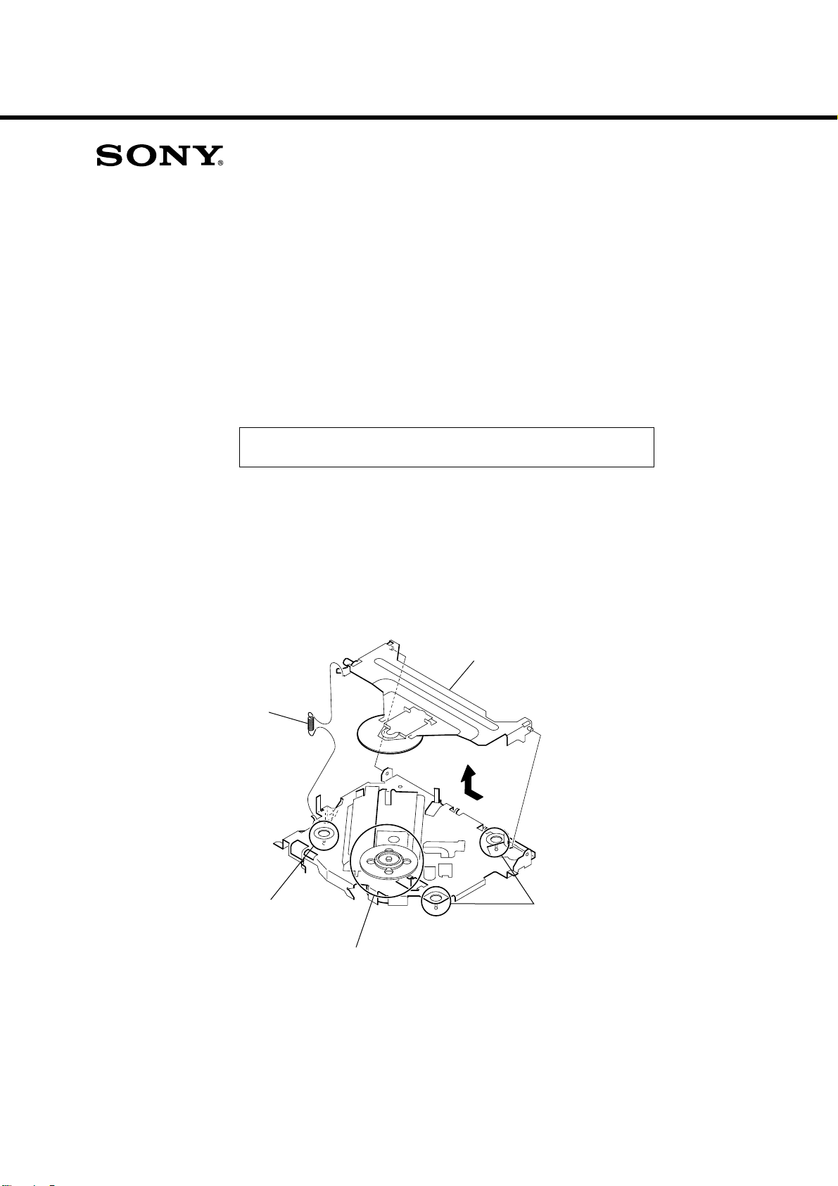
CDX-GT41UW/GT410U/
GT460U/GT460US
US Model
Canadian Model
CDX-GT41UW/GT410U
SERVICE MANUAL
Ver. 1.2 2007.03
SUPPLEMENT-1
File this supplement with the service manual.
Subject: Notes for removal of the OPTICAL PICK-UP added.
DISASSEMBLY
1. CHUCKING ARM SUB ASSY
E Model
CDX-GT460U/GT460US
Chinese Model
CDX-GT460U
1
spring
Note: Have this portion receive the chassis.
Note: Be careful not to touch the turn table.
3
chucking arm sub assy
2
Note: Have this portion receive the chassis.
9-887-470-81
Page 44
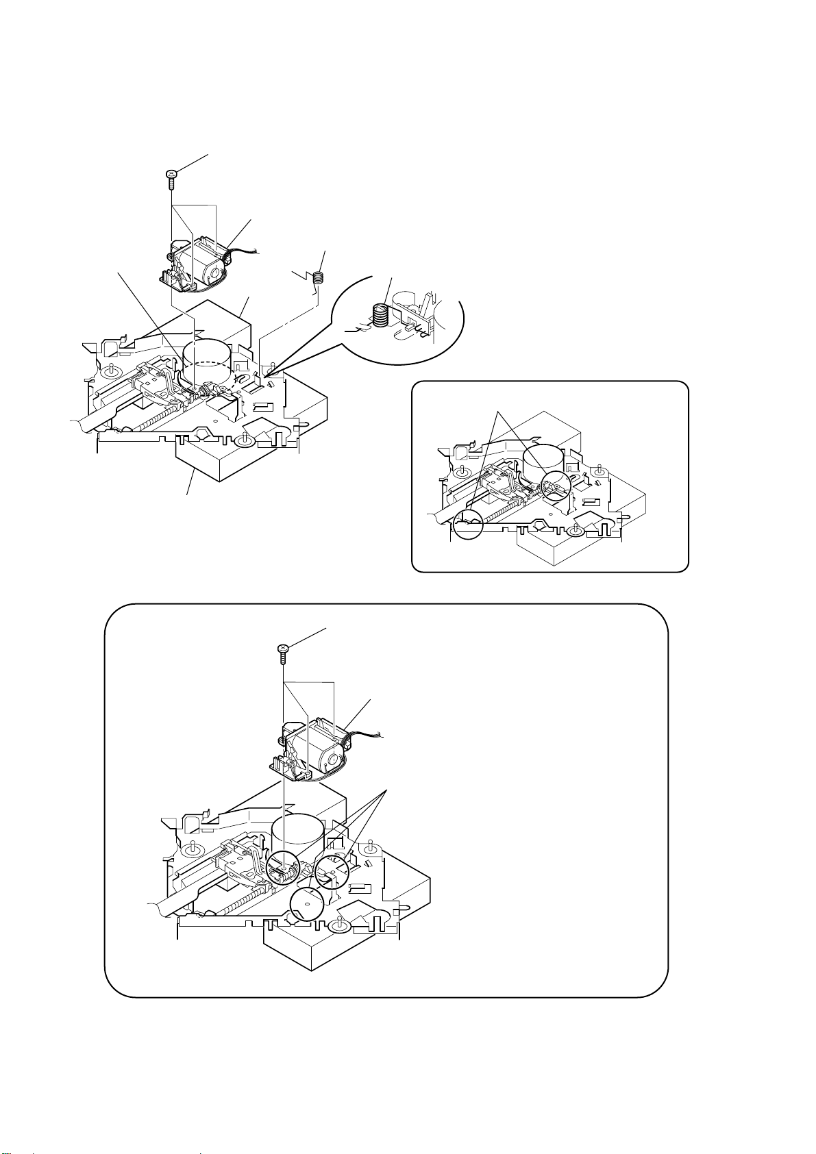
CDX-GT41UW/GT410U/GT460U/GT460US
2. SLED MOTOR ASSY
2
turn table
three serration
(M 2
×
3
stand
screws
3)
sled mtor assy
1
spring
spring
Note:
Never remove these parts since they were adjusted.
stand
Note: Place the stand with care not to touch the turn table.
Note for Assembly
three serration
(M 2
×
3)
sled mtor assy
screws
Note: Take care to prevent the chassis from being bent
when tightening the three machine screws.
2
Page 45
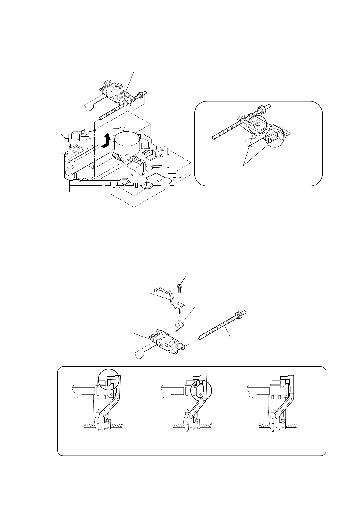
3. OPTICAL PICK-UP SECTION
1
optical pick-up section
2
CDX-GT41UW/GT410U/GT460U/GT460US
Note: Be careful not to touch the lens and hologram
terminal when removing the optical pick-up section.
4. OPTICAL PICK-UP
2
5
Notes for Assembly
leaf spring (sub guide)
optical pick-up
1
pan tapping
(M 1.4
3
leaf spring (OP)
×
2.5)
screw
4
lead screw assy
Prevent the end of the
leaf spring (sub guide) from being
in contact with the OP slide base.
Prevent the end of the
leaf spring (sub guide) from being
in contact with the OP slide base.
There is space at the end of the
leaf spring (sub guide) to avoid
contact with the slide.
3
Page 46
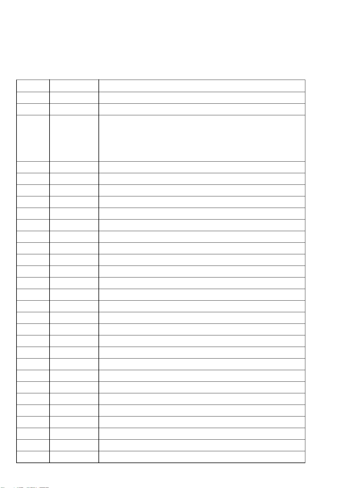
CDX-GT41UW/GT410U/GT460U/GT460US
REVISION HISTORY
Clicking the version allows you to jump to the revised page.
Also, clicking the version at the upper on the revised page allows you to jump to the next revised page.
Ver. Date Description of Revision
1.0 2006.11 New
1.1 2007.01 Indian model addition to CDX-GT460U.
1.2 2007.03 Change of MARUTI SUZUKI model. (from CDX-GT460U to
CDX-GT460US)
Notes for removal of the OPTICAL PICK-UP added.
(SUPPLEMENT-1) (ECN-ECC05660, ENG-07003)
4
 Loading...