

Page 1
CDX-565MXRF
SERVICE MANUAL
Ver 1.2 2002.12
SPECIFICATIONS
US Model
Canadian Model
E Model
Model Name Using Similar Mechanism CDX-757MX
CD Drive Mechanism Type MG-251B-137
Optical Pick-up Name KSS-720A
CD changer (CDX-565MXRF)
System Compact disc digital audio
Laser Diode Properties
Material GaAlAs
Wavelength 780 nm
Emission Duration Continuous
Laser output power Less than 44.6 µW*
*
This output is the value measured at a distance of
200 mm from the objective lens surface on the
Optical Pick-up Block.
Transmitting frequency 88.3 MHz/88.5 MHz/
Input/output terminals Wired remote control (8 pin)
Current drain 900 mA (at playback)
Operating temperature –10°C to +55°C (14°F to 131°F)
Dimensions Approx. 262 × 90 × 185 mm (10
Mass Approx. 2.1 kg (4 lb. 10 oz.)
Relay box
Input/output Antenna input terminal
Dimensions 40 × 40 × 27 mm
Mass 140 g (5 oz.)
system
88.7 MHz/88.9 MHz/
89.1 MHz/89.3 MHz/
89.5 MHz/89.7 MHz/
89.9 MHz/(switchable)
RF signal (FM) output
Power input (3 pin)
900 mA (at disc loading/
ejecting)
3
/8 × 3 5/8 × 7 3/8 in.)
(w/h/d)
Antenna output cord
CD Changer input cord
5
/8 × 1 5/8 × 1 1/8 in.)
(1
(w/h/d)
Wired remote (RM-X83RF)
/Wireless remote (RM-X84RF)
Dimensions Wired remote:
Mass Wired remote:
Battery Wireless remote:
Supplied accessories
Design and specifications are subject to change
without notice.
Approx. 127.5 × 41.5 × 24 mm
1
/8 × 1 11/16 × 31/32 in.)
(5
(w/h/d)
Wireless remote:
Approx. 52 × 8.5 × 90 mm
1
/16 × 3/8 × 3 9/16 in.)
(2
(w/h/d)
Approx. 280 g (10 oz.)
Wireless remote:
Approx. 30 g (1 oz.)
Lithium battery (CR2025)
Disc magazine (1)
Parts for installation and
connections (1 set)
9-873-927-03 Sony Corporation
2002L0500-1 e Vehicle Company
C 2002.12 Published by Sony Engineering Corporation
COMPACT DISC CHANGER SYSTEM
Page 2
CDX-565MXRF
L
SERVICING NOTES
NOTES ON HANDLING THE OPTICAL PICKUP BLOCK OR BASE UNIT
The laser diode in the optical pick-up block may suffer electrostatic breakdown because of the potential difference generated by
the charged electrostatic load, etc. on clothing and the human body .
During repair, pay attention to electrostatic breakdown and also
use the procedure in the printed matter which is included in the
repair parts.
The flexible board is easily damaged and should be handled with
care.
NOTES ON LASER DIODE EMISSION CHECK
The laser beam on this model is concentrated so as to be focused
on the disc reflective surface by the objective lens in the optical
pick-up block. Therefore, when checking the laser diode emission, observe from more than 30 cm away from the objectiv e lens.
US/Canadian model:
If the optical pick-up block is defective, please replace the whole
optical pick-up block.
Never turn the semi-fixed resistor located at the side of optical
pick-up block.
OPTICA
PICK-UP
BLOCK
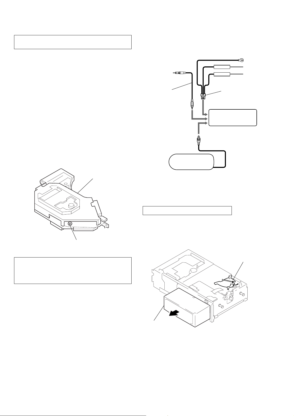
JIG ON REPAIRING
When repairing this set, connect the jig (cord) for RF output extract (Part No. J-2502-058-1) and power supply (Part No. J-2502058-2) as the figure shown below.
RF output cord
(J-2502-058-1)
wired remote commander
power supply cord
(J-2502-058-2)
compact disc changer
SEMI-FIXED
RESISTOR
CAUTION
Use of controls or adjustments or performance of procedures
other than those specified herein may result in hazardous radiation exposure.
Flexible Circuit Board Repairing
•Keep the temperature of the soldering iron around 270 ˚C during repairing.
• Do not touch the soldering iron on the same conductor of the
circuit board (within 3 times).
• Be careful not to apply force on the conductor when soldering
or unsoldering.
Notes on chip component replacement
•Never reuse a disconnected chip component.
• Notice that the minus side of a tantalum capacitor may be damaged by heat.
SAFETY-RELATED COMPONENT WARNING!!
COMPONENTS IDENTIFIED BY MARK 0 OR DO TTED LINE
WITH MARK 0 ON THE SCHEMATIC DIAGRAMS AND IN
THE PARTS LIST ARE CRITICAL TO SAFE OPERATION.
REPLACE THESE COMPONENTS WITH SONY PARTS
WHOSE PART NUMBERS APPEAR AS SHOWN IN THIS
MANUAL OR IN SUPPLEMENTS PUBLISHED BY SONY.
DISC MAGAZINE GETTING OUT PROCEDURE
ON THE POWER SUPPLY IS OFF
Remove the CASE (LOWER. T) beforehand
1) Press the lever (ML.S) assy in the direction of arrow A.
2) Removal the magazine assy.
Note: Take out the magazine only when the tray is completely within the
magazine. If the disk or tray is sticking out, turn on the power and
eject the magazine.
Lever (ML.S)
A
Magazine assy
ATTENTION AU COMPOSANT AYANT RAPPORT
À LA SÉCURITÉ!
LES COMPOSANTS IDENTIFIÉS P AR UNE MARQUE 0
SUR LES DIAGRAMMES SCHÉMATIQUES ET LA LISTE
DES PIÈCES SONT CRITIQUES POUR LA SÉCURITÉ
DE FONCTIONNEMENT. NE REMPLACER CES COMPOSANTS QUE PAR DES PIÈCES SONY DONT LES
NUMÉROS SONT DONNÉS DANS CE MANUEL OU
DANS LES SUPPLÉMENTS PUBLIÉS PAR SONY.
2
Page 3
CDX-565MXRF
TEST DISC
This set can playback a CD-R, CD-RW for audio use. When test
this set, use the following test disc.
Test disc for CD-R: TCD-R082LMT (Part No.: J-2502-063-1)
Test disc for CD-RW: TCD-W082L (Part No.: J-2502-063-2)
Notes on CD-R discs
• You can play CD-Rs/CD-RWs (recordable CDs/rewritable CDs)
on this unit (fig.
• Some CD-Rs (depending on the equipment used for its recording
or the condition of the disc) may not play on this unit.
• You cannot play a CD-R that is not finalized*.
•A CD-R/CD-RW to which a session can be added can be played.
*
A process necessary for a recorded CD-R disc to be played on the audio
CD player.
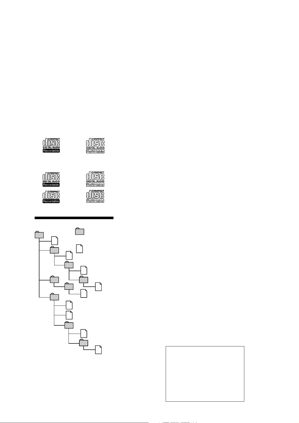
H).
H
Audio CD
MP3 files
About MP3 files
Folder (album)
1
1
MP3 file (track)
2
2
3
3
4
5
6
6
7
4
5
7
8
8
9
Tree 1 Tree 2 Tree 3 Tree 4 Tree 5
(root)
MP3 (MPEG 1 Audio Layer-3) is a standard technology and format for
compressing a sound sequence. The file is compressed to about 1/10 of its
original size. Sounds outside the range of human hearing are compressed
while the sounds we can hear are not compressed.
Notes on discs
You can play MP3 files recorded on CD-ROMs, CD-Rs (recordable CDs),
and CD-RWs (rewritable CDs). The disc must be in the ISO 9660*
level 2 format, or Joliet or Romeo in the expansion format. You can use a
disc recorded in Multi Session*
*1ISO 9660 Format
The most common international standard for the logical format of files
and folders on a CD-ROM.
There are several specification levels. In Level 1, file names must be in
the 8.3 format (no more than eight characters in the name, no more than
three characters in the extension “.MP3”) and in capital letters. Folder
names can be no longer than eight characters. There can be no more
than eight nested folder levels.
In level 2, file names can be up to 31 characters long (including the
delimiter, the dot “.”, and the extension “. MP3”). Each folder can have
up to 8 trees.
For Joliet or Romeo in the expansion format, make sure of the contents
of the writing software, etc.
*2Multi Session
This is a recording method that enables adding of data using the TrackAt-Once method. Conventional CDs begin at a CD control area called
the Lead-in and end at an area called Lead-out. A Multi Session CD is a
CD having multiple sessions, with each segment from Lead-in to Leadout regarded as a single session.
CD-Extra: A format that contains audio tracks (audio CD data) in
Session 1, and a data track in Session 2.
Mixed CD: A format that contains a data track and audio tracks (audio
Notes
• If MP3 files and Audio data are mixed in a disc, the first identified
• With formats other than ISO 9660 level 1, folder names or file
• When naming, be sure to add the file extension “.MP3” to the file
• If you put the extension “.MP3” to a file other than MP3, the unit
The playback order of the MP3 files
The playback order of the folders and files is shown in the illustration
above.
Notes
•A folder that does not include an MP3 file is skipped.
•If you playback an MP3 file before the information on all the CDs
• The unit reads the disc information (the number of folders and
•When a disc magazine is inserted into the CD changer or the reset
• The following discs take a longer time to start playback.
• Depending on the condition of the disc, it may not play back. For
•Maximum folder number in a disc: 255
•Maximum file number in a disc: 511
Cautions when playing a disc that is recorded in Multi Session
• When the first track of the first session is audio CD data: Non-music data
• When the first track of the first session is not audio CD data:
Note on character codes
Character codes vary depending on the master unit.
For details, refer to the operating instructions for the master unit.
Note on display of playing time
In the following cases, elapsed playing time may not be displayed
accurately.
– when an MP3 file of VBR (variable bit rate) is played.
– during fast-forward/reverse.
Tip
• To specify a desired playback order, before the folder or file
•A disc/album/track name or track number that is over 99 may not
CD data) in a session.
file or data will be played back.
names may not be displayed correctly.
name.
cannot recognize the file properly and will generate random noise
that could damage your speakers.
in the disc magazine has been read, and then set the ignition to
OFF or select another source, the beginning of the current track
may play back when you resume playback.
files, or the location of the data) before playback of an MP3 file. It
may take more time to start playback of a disc with a complex file
structure.
button of the connected car audio is pressed, the unit will
automatically be activated and read the information on the CDs.
When the information on all the CDs in the disc magazine has
been read, the unit will automatically stop operation. The unit
firstly reads all of the disc information in the disc magazine.
Depending on the recording method, it may take some time to
stop the operation even if you set the ignition key to OFF during
disc reading. This is not a malfunction.
–a disc recorded with complicated tree structure.
–a disc recorded in Multi Session.
–a disc to which data can be added.
We recommend that you make only one or two trees for each disc.
details, please refer to “Notes on discs.”
empty folders)
* Maximum number of files and folders: 512
When a file/folder name contains many characters, this number
may become less than 512.
information (track number, time, etc.) is displayed with no sound.
– Audio CD data is played back normally; other data is played back with
no sound. (MP3 file(s) cannot be played back.)
– If no MP3 file is in the disc, “NO Music” is displayed and nothing is
played back. (Audio CD data is not recognized.)
name, input the order by number (e.g., “01,” “02”), then record
contents onto a disc. (The order differs depending on the writing
software.)
be displayed accurately when this unit is connected to a master
unit that does not support MP3. A master unit that supports MP3
is recommended.
About ID3 tag version 2
Although not a malfunction, the following occurs when
an MP3 file containing ID3 tag ver.2 is played:
– When skipping a portion of ID3 tag ver.2 (at the
beginning of the track), sound is not output.
Skip time changes depending ID3 tag ver.2 capacity.
Example: At 64 kbytes, it is about 2 seconds
(with RealJukebox).
– The displayed elapsed playing time when skipping a
portion of ID3 tag ver.2 is inaccurate.
For MP3 files of a bit rate other than 128 kbps, time is
not displayed accurately during playback.
– When an MP3 file is created with MP3 conversion
software (ex. RealJukebox*), ID3 tag ver.2 will
automatically be written.
* “RealJukebox is a registered trademark of
RealNetworks, Inc.”
As of December, 2001
2
.
*
(including root folder and
*
1
level 1 or
3
Page 4
CDX-565MXRF
FAQ- about MP3 Audio File
Q1 What is MP3?
MP3 (MPEG Audio Layer3) is a standard
for compressing audio parts of Moving
Pictures Experts Group (MPEG).
The special feature of MP3 is that the music
data is compressed to about 1/10 of its
original size while retaining the same
sound quality as a CD or an MD.
Compared with an audio disc (maximum
74 minutes running time), MP3 lets you
compress about 10 audio discs or 160 fourminute songs into a CD-R/RW of 650MB.
Note
Recorded music is limited to private use only. Use
of music beyond this limit requires the permission
of the copyright holders. Copyright law prohibits
copying, distributing, or delivering all or part of
the contents.
Q2 What kind of MP3 files can be
played back?
MP3 files in CD-ROMs, CD-Rs, and CDRWs can be played.
Pay attention to the following points when
creating MP3 data CDs using your
computer, CD-R/RW drive, writing
software, or MP3 file.
• The file must be in the ISO 9660 level 1 or
level 2 format, or Joliet or Romeo in the
ISO 9660 expansion format.
A folder name or a file name with the
format other than ISO 9660 level 1 may
not be displayed correctly. When
creating MP3 data CDs, the format of ISO
9660 level 1 is recommended.
• When naming, be sure to add the file
extension “.MP3” to the MP3 file name.
The unit cannot recognize an MP3 file
without the extension “.MP3,” or a file
that is not MP3 format, even with the
extension “.MP3.”
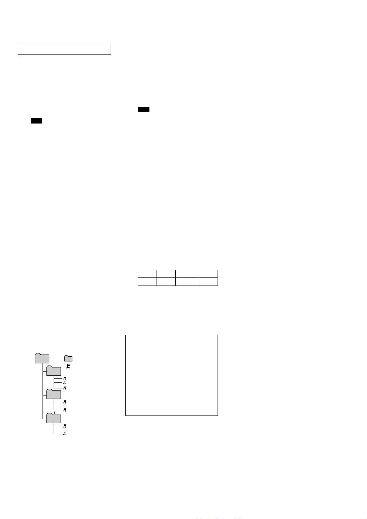
Q3 Is there maximum number of
folders or files to play?
Pay attention to the maximum numbers
mentioned below.
•Maximum folder number in a disc: 255*
(including root folder and empty folders)
•Maximum file number in a disc: 511*
* Maximum number of files and folders:
512
When a file/folder name contains
many characters, this number may
become less than 512.
• The maximum number of trees which
can be played is 8.
The unit allows you to change the folders,
to play just the files in your favorite folder
repeatedly, or to play files randomly, create
folders according to artist name or album,
and put related MP3 files into folders to use
the unit as a CD changer.
ROOT
01_
ALBUM
02_
ALBUM
10_
ALBUM
: Folder
: MP3 file
001TRACK.MP3
002TRACK.MP3
...
010TRACK.MP3
011TRACK.MP3
...
020TRACK.MP3
091TRACK.MP3
...
100TRACK.MP3
Q4 Can the unit play a data CD with
folder levels?
The unit can play a data CD with folder
levels.
Q5 Is there any restriction about the
bit rate regarding playback of
MP3 files?
There is no specific restriction, but a bit rate
of more than 128kbps is recommended
from the perspective of sound quality. The
unit also supports VBR (Variable Bit Rate).
Note
Elapsed playing time may not be displayed
accurately during cue/reverse.
Q6 Does the unit support a disk of
80 minutes running time (700
MB data capacity)?
The unit supports a disk of 80 minutes
running time (700 MB data capacity).
Q7 Can the unit play a CD-R/RW
containing both music CD data
(CD-DA) and MP3 file data?
The first identified file or data will be
played back.
Q8 Can the unit play a disc to which
data can be added (non-finalized
disc)?
The unit can play a non-finalized disc.
Q9 Can the unit play a Multi Session
disc?
The unit can play a Multi Session disc. For
details, refer to the operating instructions.
Q10 Does the unit support Emphasis?
The unit does not support Emphasis.
Q11 What is the sampling rate
supporting the unit?
The unit is supported from 16kHz to
48kHZ.
MPEG1 48kHz 44.1kHz 32kHz
MPEG2 24kHz 22.05kHz 16kHz
Q12 Does the unit support the play
list of m3u?
The unit does not support the play list of
m3u.
Q13 Does the unit support ID3-Tag?
The unit supports ID3 tag ver.1.
Pay attention to the following points about
ID3 tag ver.2.
About ID3 tag version 2
Although not a malfunction, the following occurs
when an MP3 file containing ID3 tag ver.2 is
played:
–When skipping a portion of ID3 tag ver.2 (at the
beginning of the track), sound is not output. Skip
time changes depending ID3 tag ver.2 capacity.
Example: At 64 kbytes, it is about 2 seconds
(with RealJukebox).
– The displayed elapsed playing time when skipping
a portion of ID3 tag ver.2 is inaccurate.
For MP3 files of a bit rate other than 128 kbps, time
is not displayed accurately during playback.
– When an MP3 file is created with MP3 conversion
software (ex. RealJukebox*), ID3 tag ver.2 will
automatically be written.
* “RealJukebox is a registered trademark of
RealNetworks, Inc.”
As of December, 2001
Q14 Is a file name/a folder name of
MP3 different from the name
when creating a data CD (the
name displayed on your
computer)?
On this unit, a file name/a folder name is
displayed as below.
•A file name/a folder name can be
displayed up to 8 characters.
th
or later character cannot be
A 9
displayed or scrolled.
•A folder name or a file name in a format
other than ISO 9660 level 1 may not be
displayed correctly. The file name should
only use one byte uppercase, one byte
numeric characters, or an underscore
(“__”). It should also be no more than 8
characters long, and with no more than
three characters in the extension.
• Japanese phonetic symbols/ Chinese
characters cannot be displayed.
Only one byte uppercase (A-Z), one byte
numeric character (0-9), and one byte
“_”, “.”,
symbol (
can be displayed. One byte lowercase (az) is changed to an uppercase character,
and any other characters are displayed as
“*”.
“<”, “>”, “/”, “+”, “*”)
Q15 MP3 files recorded onto a CD-R/
RW cannot be played.
This may happen in following cases.
• The recording method onto CD-R/RW is
the packet write method.
• The extension file is not an “.MP3.”
• The file data is not MP3 format.
• Some recording condition (omission of
data, etc.) or some disc condition (dirt,
crack, curving, etc.) may cause inability
to playback an MP3 file.
Q16 It takes some time to start
playback of MP3 file.
The unit reads the disc information (the
number of folders and files, or the location
of the data) before playback of MP3 file. It
may take more time to start playback of a
disc with many trees.
Please refer to the instruction manual for
details.
Q17 Playback skipping and no
playback occur.
Recording condition onto CD-R/RW
(omission of data, etc.) or disc condition
(dirt, crack, curving, etc.) may cause
playback skipping or no playback.
Q18 Can WAVE files be played back
on this unit?
WAVE files cannot be played back on this
unit.
Q19 Can other compressed formats,
such as ATRAC3, be played back
on the unit?
Only MP3 can be played back on the unit.
4
Page 5

TABLE OF CONTENTS
SERVICING NOTES .......................................................... 2
1. GENERAL
Location and function of Controls.................................. 6
Installation....................................................................... 9
Connections..................................................................... 10
2. DISASSEMBLY
2-1. Disassembly Flow ........................................................... 11
2-2. Case (Upper. T), Front Panel Assy ................................. 12
2-3. Mechanism Deck (MG-251B-137)................................. 12
2-4. FM Board ........................................................................ 13
2-5. MAIN Board, Slide Variable Resistor
(Elevator Height Sensor) (RV202) ................................. 13
2-6. ELJ Motor Assy (Elevator) (M104) ................................ 14
2-7. Escutcheon (T) ................................................................ 14
2-8. Chassis (U.S) Sub Assy .................................................. 15
2-9. Chassis Assy.................................................................... 15
2-10. RF Board ......................................................................... 16
2-11. Sled Motor Assy (251) (M101),
Optical Pick-up (KSS-720A) .......................................... 16
2-12. LSW Board, Spindle Motor (S) Sub Assy (M102) ........ 17
2-13. ELJ Motor Assy (Chucking) (M103) ............................. 17
CDX-565MXRF
3. ASSEMBLY
3-1. Assembly Flow................................................................ 18
3-2. Optical Pick-up Complete Assy...................................... 18
3-3. Gear (Lomini)/(Load 1) Assy ......................................... 19
3-4. Operation Check ............................................................. 19
4. MECHANICAL ADJUSTMENT.......................... 20
5. ELECTRICAL CHECK .......................................... 21
6. DIAGRAMS
6-1. Block Diagram – SERVO Section – .............................. 22
6-2. Block Diagram – MAIN Section (1/2) – ....................... 23
6-3. Block Diagram – MAIN Section (2/2) – ....................... 24
6-4. Note for Printed Wiring Boards and
Schematic Diagrams ....................................................... 25
6-5. Printed Wiring Boards – RF/LSW Boards – ................. 26
6-6. Schematic Diagram – RF/LSW Boards –...................... 27
6-7. Printed Wiring Boards
– MAIN Board (Component Side) – .............................. 28
6-8. Printed Wiring Boards
– MAIN (Conductor Side)/EJECT Boards –.................. 29
6-9. Schematic Diagram – MAIN Board (1/3) – .................. 30
6-10. Schematic Diagram
– MAIN (2/3)/EJECT Boards – ...................................... 31
6-11. Schematic Diagram – MAIN Board (3/3) – .................. 32
6-12. Printed Wiring Boards – FM Board –............................ 34
6-13. Schematic Diagram – FM Board –................................. 35
6-14. IC Pin Function Description ........................................... 40
7. EXPLODED VIEWS
7-1. General Section-1............................................................ 43
7-2. General Section-2............................................................ 44
7-3. Mechanism Deck Section-1 (MG-251B-137) ................ 45
7-4. Mechanism Deck Section-2 (MG-251B-137) ................ 46
7-5. Mechanism Deck Section-3 (MG-251B-137) ................ 47
7-6. Mechanism Deck Section-4 (MG-251B-137) ................ 48
8. ELECTRICAL PARTS LIST ............................... 49
5
Page 6
CDX-565MXRF
SECTION 1
GENERAL
This section is extracted from
instruction manual.
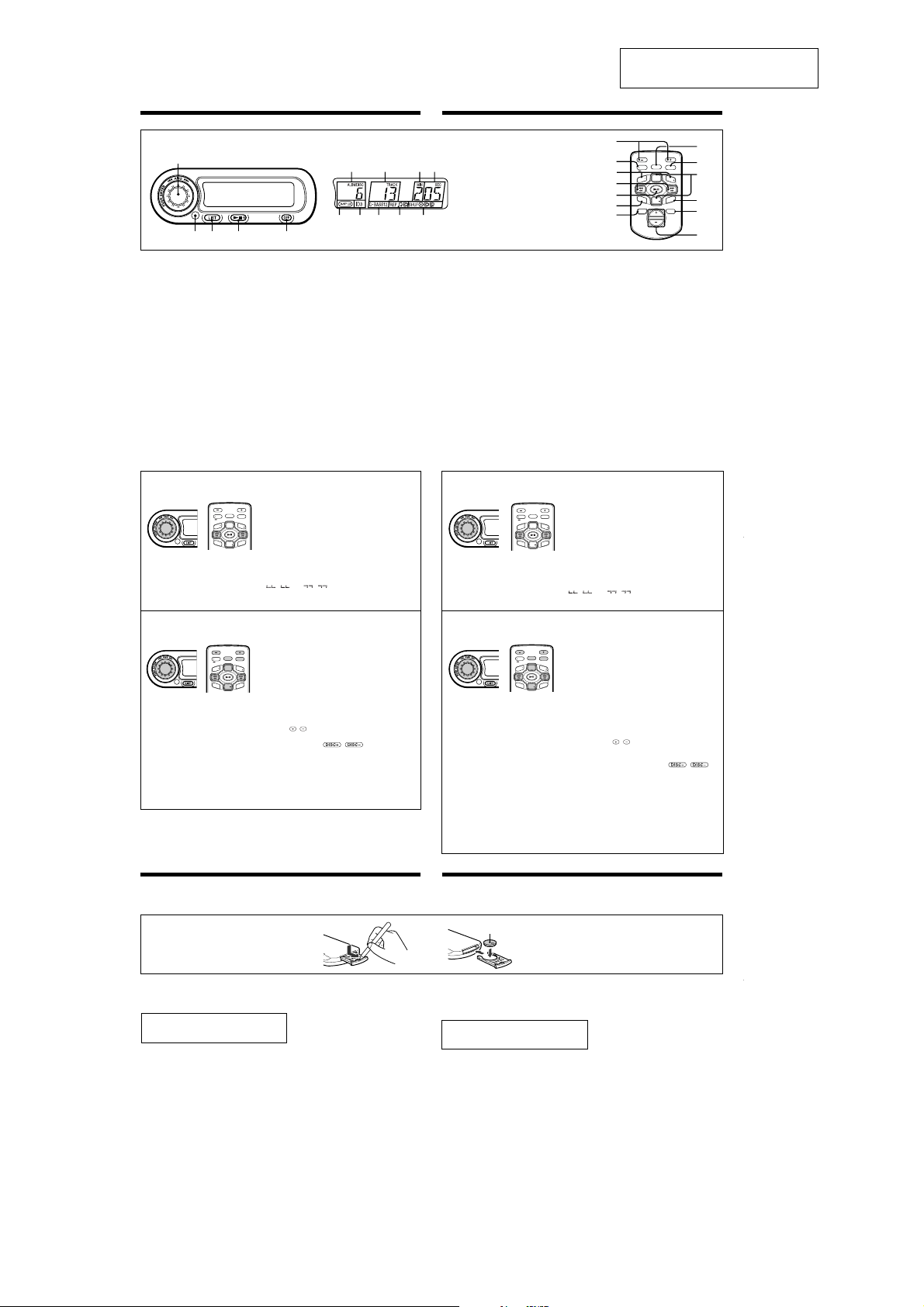
Location and function of controls
Wired remote (RM-X83RF)
Télécommande à fil (RM-X83RF)
1
23 4
1AMS (Automatic Music Sensor)/ENTER
dial
2Infrared receptor for the wireless
remote
3LIST button
4u (play/pause) button
If pressed during CD playback, the CD will pause.
If pressed again, CD playback will continue.
5OFF button
6DISC/ALBM (disc number/album number)
indication
7TRACK (track number) indication
8MIN (minute) indication
9SEC (second) indication
0MP3 file indication
Available only when a disc with MP3 files is
selected.
qaID3 tag indication
Available only when an MP3 file is played.
qsD-BASS indication
qdREP (repeat play) indication
qfSHUF (shuffle play) indication
qg–/+ buttons
qhDSPL/SCRL (indication change/name
scroll) button
LIST
ENTER DSPL
SCRL
+
A
DISC
L
B
M
M
B
L
A
REP
F
U
H
S
(Wired remote) (Wireless remote)
(Wired remote) (Wireless remote)
DISC
LIST
ENTER DSPL
SCRL
+
A
DISC
L
B
M
M
B
L
A
REP
F
U
H
S
DISC
67 9
0qaqsqd
5
qjALBM –/+ (album select) buttons
Skips to the next/previous album. Note that if the
last album is playing and the ALBM + button is
pressed, playback loops back to the first album. Or
if the first album is playing, and the ALBM –
button is pressed, playback loops to the last album.
Available only when an MP3 file is played.
qkAMS/MANU (Automatic Music Sensor/
manual search) buttons
qlREP (repeat play) button
w;ENTER button
waDISC +/– buttons
wsSHUF (shuffle play) button
wdD-BASS button
wf10 TRACK +/– buttons
By pressing the 10 TRACK + or – buttons, the unit
skips forwards or backwards 10 tracks (either
within the current album, or into the next/
previous album (still counting 10 tracks),
depending on the number of tracks in the current
album). Note that if any of last 10 tracks of the disc
is playing and the 10 TRACK + button is pressed,
playback loops back to the beginning of the disc
and continues counting to make a 10-track skip. Or
if any of first 10 tracks of the disc is playing, and
the 10 TRACK – button is pressed, playback loops
back to the end of the disc and continues counting
to make a 10-track skip.
AMS function
Keep rotating the AMS/ENTER dial until a desired track is
selected.
Next track: Rotate the AMS/ENTER dial towards > .
Previous track: Rotate the AMS/ENTER dial towards ..
While the first/last track on the disc is playing, if the AMS/
ENTER dial is rotated, playback skips to the last/first track of
the disc.
Using on the wireless remote
Press AMS/MANU m ./> M to skip/select a track.
Manual search function (Only for the wireless
remote)
Keep pressing AMS/MANU m ./> M until a
desired point of the track is selected.
The elapsed playing time of the track will be shown in the
display window during manual search.
“
” or “ ” indicates that the disc has reached
the beginning/end of the track. It is not possible to reverse/
fast-forward at this point.
Disc select function
1
Press (LIST).
The disc name during playback will flash.
“MP3 DISC” will be displayed if a disc with an MP3 file is
selected.
2
Rotate the AMS/ENTER dial to select a desired disc.
3
Press the AMS/ENTER dial to start playback.
Notes
The following indications may be displayed in the following cases.
• “NO DISC”: No disc is inserted in the CD changer.
• “NO NAME”: No disc name is available.
• “NOT READ”: The disc information cannot be read.
Using on the wireless remote
1
Press (LIST).
2
Press / to select a desired disc.
3
Press (ENTER) to start.
Also, you can press / to select a disc.
The next/previous disc will be selected by each press.
Notes
• The display window will be back to normal without an
operation for 5 seconds during the disc select function.
• The disc select function is unavailable during “Changing the
transmitting frequency” or “Changing the output level”
procedure.
Tip
Press (LIST) to cancel the disc select function before step 3.
Nomenclature
Wireless remote (RM-X84RF)
Télécommande sans fil (RM-X84RF)
8
qf
1 Molette AMS (détecteur automatique de
musique)/ENTER
2 Récepteur de télécommande sans fil IR
3 Touche LIST
4 Touche u (lecture/pause)
Si vous appuyez sur cette touche en cours de
lecture CD, le CD passe en mode de pause. Si vous
appuyez de nouveau sur cette touche, la lecture
CD reprend.
5 Touche OFF
6 Indicateur DISC/ALBM (numéro de
disque ou d’album)
7 Indicateur TRACK (numéro de plage)
8 Indication MIN (minute)
9 Indication SEC (seconde)
0 Indicateur de fichier MP3
Disponible uniquement lorsqu’un disque
comportant des fichiers MP3 est sélectionné.
qa Indicateur d’étiquette ID3
Disponible uniquement lors de la lecture d’un
fichier MP3.
qs Indication D-BASS
qd Indication REP (répétition de la lecture)
qf Indication SHUF (lecture aléatoire)
qg Touches –/+
qh Touche DSPL/SCRL (changement
d’indicateur/défilement du nom)
(Télécommande sans fil)(Télécommande à fil)
(Télécommande sans fil)(Télécommande à fil)
qg
qh
SCRL
qj
BM
AL
qk
4
R
E
P
ql
OFF
5
3
w;
LIST
ENTER DSPL
wa
+
A
DISC
L
B
M
F
U
H
S
DISC
ws
D-BASS
wd
10TRACK
wf
qjTouches ALBM –/+ (sélection d’album)
Permettent de passer à l’album précédent ou
suivant. Notez que si le dernier album est en cours
de lecture et que la touche ALBM + est enfoncée, la
lecture revient au premier album. De même, si le
premier album est en cours de lecture et que la
touche ALBM – est enfoncée, la lecture revient au
dernier album.
Disponibles uniquement lors de la lecture d’un
fichier MP3.
qkTouches AMS/MANU (détecteur
automatique de musique/recherche
manuelle)
qlTouche REP (lecture répétée)
w;Touche ENTER
waTouches DISC +/–
wsTouche SHUF (lecture aléatoire)
wdTouche D-BASS
wfTouches 10 TRACK +/–
Lorsque vous appuyez sur la touche 10 TRACK +
ou –, l’appareil saute dix plages vers l’avant ou
vers l’arrière (soit dans l’album en cours, soit dans
l’album suivant ou précédent, dix plages à la fois,
selon le nombre de plages de l’album en cours).
Notez que si l’une des dix dernières plages du
disque est en cours de lecture et que la touche 10
TRACK + est enfoncée, la lecture revient au début
du disque et continue à sauter des plages jusqu’à
un total de dix plages. Notez que si l’une des dix
premières plages du disque est en cours de lecture
et que la touche 10 TRACK – est enfoncée, la
lecture passe à la fin du disque et continue à sauter
des plages jusqu’à un total de dix plages.
Fonction AMS
Tournez la molette AMS/ENTER jusqu’à ce que vous ayez
sélectionné la plage souhaitée.
Plage suivante : Tournez la molette AMS/ENTER vers > .
Plage précédente : Tournez la molette AMS/ENTER vers ..
Pendant que la première ou la dernière plage du disque est en
cours de lecture, si vous tournez la molette AMS/ENTER, la
LIST
ENTER DSPL
SCRL
lecture passe à la première ou à la dernière plage du disque.
+
A
DISC
L
B
M
M
B
L
A
SCRL
L
A
R
Utilisation de la télécommande sans fil
Appuyez sur AMS/MANU m ./> M pour sauter ou
REP
F
U
sélectionner une plage.
H
S
DISC
Fonction de recherche manuelle (Télécommande
sans fil uniquement)
Maintenez enfoncée AMS/MANU m ./> M jusqu’à
ce que vous ayez sélectionné le point souhaité de la plage.
Le temps de lecture écoulé de la plage est indiqué dans la
fenêtre d’affichage en cours de recherche manuelle.
“
” ou “ ” indique que le disque a atteint le
début ou la fin de la plage. À ce point, il n’est pas possible de
reculer ou d’avancer rapidement.
Fonction de sélection de disque
1
Appuyez sur (LIST).
Le nom du disque clignote en cours de lecture.
“MP3 DISC” s’affiche si un disque contenant un fichier
MP3 est sélectionné.
2
LIST
DISC
M
B
EP
DISC
Faites tourner la molette AMS/ENTER pour
ENTER DSPL
sélectionner le disque souhaité.
+
A
L
B
M
3
Appuyez sur la molette AMS/ENTER pour lancer la
lecture.
F
U
H
S
Remarques
Les indications ci-dessous peuvent s’afficher dans les cas suivants.
• “NO DISC” : Aucun disque n’a été inséré dans le changeur CD.
• “NO NAME” : Aucun nom de disque n’est disponible.
• “NOT READ” : Impossible de lire les informations du disque.
Utilisation de la télécommande sans fil
1
Appuyez sur (LIST).
2
Appuyez sur / pour sélectionner le disque
souhaité.
3
Appuyez sur (ENTER) pour commencer.
Vous pouvez également appuyer sur /
pour sélectionner un disque.
Chaque pression permet de sélectionner le disque suivant
ou précédent.
Remarques
• Pendant que la fonction de sélection de disque est activée, la
fenêtre d’affichage revient à l’affichage normal si aucune
opération n’est effectuée pendant cinq secondes.
• La fonction de sélection de disque n’est pas disponible pendant
les procédures de changement de fréquence de transmission ou
de changement de niveau de sortie.
Conseil
Pour désactiver la fonction de sélection de disque avant l’étape 3,
appuyez sur (LIST).
Installing the battery
Replace the battery with a new CR2025 lithium battery. Use of any another battery may present a risk of fire or
explosion.
Installation de la pile
Remplacez la pile par une nouvelle pile au lithium CR2025. L’utilisation de tout autre type de pile peut poser un
risque d’incendie ou d’explosion.
+ side up
Côté + vers le haut
c
Lithium battery life
When the battery becomes weak, you will not be able to operate the unit with the wireless remote.
Battery life is approx. six months depending on the conditions of use.
WARNING
Battery may explode if mistreated.
Do not recharge, disassemble or dispose of in fire.
Notes on the lithium battery
• Keep the lithium battery out of the reach of children.
Should the battery be swallowed, immediately consult a doctor.
• Wipe the battery with a dry cloth to assure a good contact.
• Be sure to observe the correct polarity when installing the battery.
• Do not hold the battery with metallic tweezers, otherwise a short-circuit may occur.
Autonomie de la pile au lithium
Lorsque les piles s’épuisent, il ne vous sera plus possible de commander l’appareil à l’aide de la télécommande
sans fil.
L’autonomie de la pile est d’environ six mois suivant les conditions d’utilisation.
ATTENTION
Utilisée de façon incorrecte, la pile peut exploser.
Ne pas la recharger, la démonter ni la jeter au feu.
Remarques sur la pile au lithium
• Gardez les piles au lithium hors de la portée des enfants.
En cas d’ingestion, consultez immédiatement un médecin.
• Essuyez la pile à l’aide d’un chiffon sec de façon à assurer un bon contact.
• Respectez la polarité de la pile lorsque vous l’installez.
• Ne saisissez pas la pile à l’aide d’une pince métallique, sinon vous risquez de provoquer un court-circuit.
6
Page 7
CDX-565MXRF
Operation
Resetting the unit
Before operating the unit for the first time or after replacing the car battery, you must reset the unit.
Press the reset button with a pointed object, such as a ball-point pen, etc.
Reset button Touche de réinitialisation
Listening to a CD
Turn on the FM tuner of your car audio.
1
2
Tune in the selected transmitting frequency*
with the FM tuner of your car audio.
* The frequency of the unit is set to 88.3 MHz at the
factory.
You can change the frequency. (See “Changing the
transmitting frequency” below. )
3
Press u.
CD playback starts.
4
Adjust the volume with the volume control
on your car audio.
All the tracks play from the beginning.
Stopping CD play
Press (OFF).
Notes
• When CD playback stops, you may hear some noise
from the speakers. To prevent this from happening,
turn the volume of your car audio down before
stopping CD playback.
• If you turn off the ignition switch of your car without
stopping CD playback, it will automatically resume CD
playback from where it was stopped when you turn on
the ignition switch again.
• The unit cannot be turned on with the wireless
remote. Press u on the wired remote to turn on the
unit.
Listening to the radio or a tape
Be sure to stop CD playback before you start listening
to the radio or a tape.
Note
Be sure to stop CD playback, otherwise there may be
some interference with radio reception.
Playing tracks in random order
— Shuffle Play (Only for the wireless remote)
You can select:
•SHUF-ALBM* (
current album in random order.
•SHUF-DISC (
current disc in random order.
•SHUF-CHGR (
random order.
* Available only for MP3 files.
During playback, press (SHUF) repeatedly
until the desired setting appears in the
display.
Shuffle Play starts.
To return to normal play mode, select “SHUF-OFF.”
Playing tracks repeatedly
— Repeat Play (Only for the wireless remote)
You can select:
•REP-TRACK (
•REP-ALBM* (
•REP-DISC (
* Available only for MP3 files.
During playback, press (REP) repeatedly
until the desired setting appears in the
display.
Repeat Play starts.
To return to normal play mode, select “REP-OFF.”
Display items
(Only for the wireless remote)
Press (DSPL) to select the following items.
DISC/ALBUM*1 number
Displayable items
•Track number/Elapsed playing time
•Disc name*
•Album (folder) name*
•Track (file) name*1 *
•ID3 tag*
*1Only for MP3 files.
Only track name/artist name/album name in ID3 tag is
displayed.
If there is no ID3 tag, “NO ID3” will be displayed for a
moment followed by Track number/Elapsed playing
time.
2
If there is no disc name or track name, “NO NAME”
*
will be displayed for a moment followed by Track
number/Elapsed playing time.
3
Only for CD TEXT discs with the artist name.
*
Notes
•Disc name, artist name, and track title can be displayed
with up to 8 characters.
• Some characters cannot be displayed.
• This unit cannot display the artist name for each track
of a CD TEXT disc.
Notes on MP3
•ID3 tag applies only to version 1.
• Some characters cannot be displayed. Characters and
signs which cannot be displayed appear as
“ *.”
The maximum number of characters for album (folder)
names/track (file) names that can be displayed is 64
each. ID3 tag is up to 30 characters.
•In the following cases, elapsed playing time may not
be displayed accurately.
— when an MP3 file of VBR (variable bit rate) is
played.
— during fast-forward/reverse.
A display item that exceeds 8 characters will be
scrolled automatically. Press (DSPL) for 2 seconds for
further scrolling.
) — to play the tracks on the
) — to play the tracks on the
) — to play all the discs in
“SHUF” indicator is displayed.
) — to repeat a track.
) — to repeat an album.
) — to repeat a disc.
“REP” indicator is displayed.
2
3
/Artist name*
1
2
1
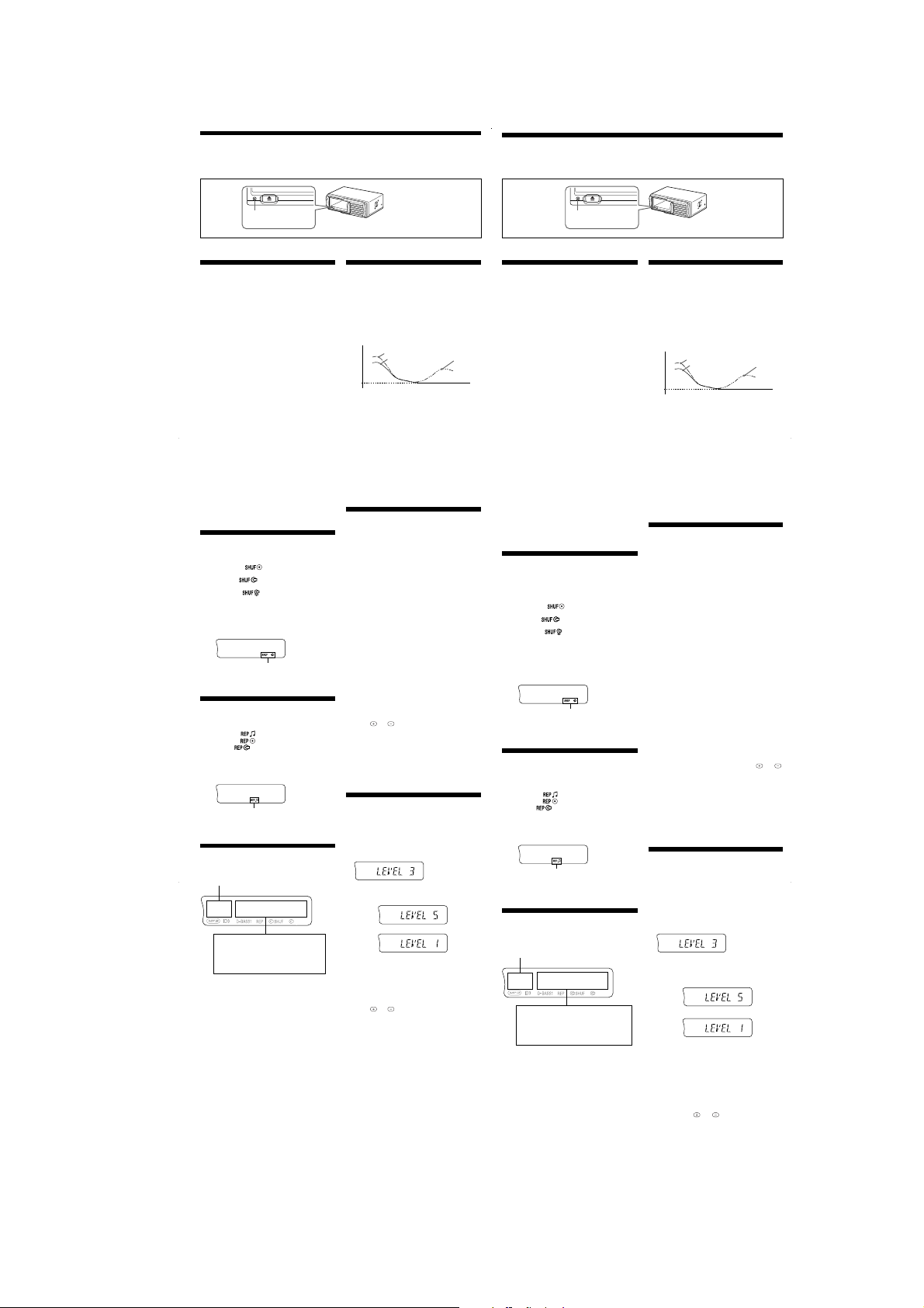
Boosting the bass sound
— D-bass (Only for the wireless remote)
You can enjoy a clear and powerful bass sound. The
D-bass function boosts the low frequency signal and
high frequency signal with a sharper curve than
conventional bass boost.
You can hear the bass line more clearly even while the
vocal volume remains the same. You can emphasize
and adjust the bass sound easily with the (D-BASS)
button.
D-BASS 2
D-BASS 1
0dB
Adjusting the bass curve
Press (D-BASS) repeatedly to select the desired
bass curve.
As the D-BASS number increases so does the
effect.
To cancel the D-bass function, select “D-BASS OFF.”
Notes
• Setting the output level from 4 to 5 while using the
D-bass function, the amount of bass boost decreases to
avoid distortion; however, it’s not a malfunction.
Adjust the volume with your car audio.
• Selecting D-BASS 2, a distortion may occur depending
on your CD.
Should this occur, select D-BASS or turn down the
output level.
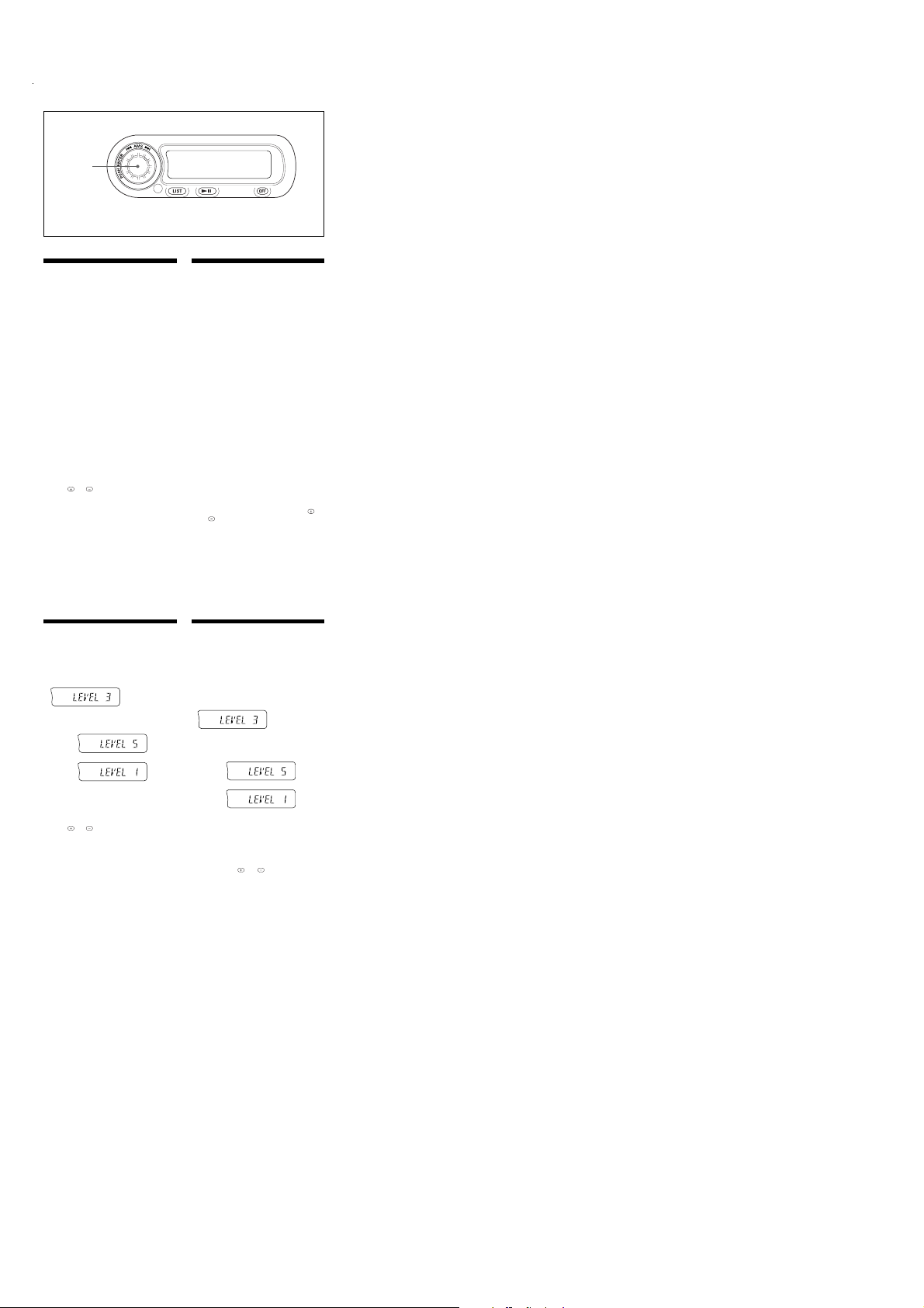
Changing the transmitting
frequency
Because this unit processes CD playback sound
through an FM tuner, there may be interference noise
during CD playback. In such a case, change the
frequency of the modulated RF signal transmitted
from the unit. The initial setting is 88.3 MHz.
1
Press the AMS/ENTER dial for two seconds
until frequency appears.
2
Rotate the AMS/ENTER dial repeatedly to
select the frequency.
Each time you rotate the AMS/ENTER dial, the
frequencies change as follows:
Right: 88.3 MHz t 88.5 MHz t 88.7 MHz t
88.9 MHz t 89.1 MHz t 89.3 MHz t
89.5 MHz t 89.7 MHz t 89.9 MHz t
88.3 MHz
Left: 88.3 MHz t 89.9 MHz t 89.7 MHz t
89.5 MHz t 89.3 MHz t 89.1 MHz t
88.9 MHz t 88.7 MHz t 88.5 MHz t
88.3 MHz
3
Press the AMS/ENTER dial for two seconds.
Using on the wireless remote
1
Press (ENTER) for two seconds until
frequency appears.
2
Press or repeatedly to select the
frequency.
3
Press (ENTER) for two seconds.
Notes
• When you change the transmitting frequency on the
unit, be sure to tune your FM tuner to the newly
selected one.
• Press u on the wired remote before changing the
frequency if the power to the unit is turned off.
Changing the output level
You can select the output level from the unit.
Normally the unit is used at the initial output level;
change the level if necessary.
1
Press the AMS/ENTER dial for two seconds
until frequency appears.
2
Press the AMS/ENTER dial momentarily.
Initial setting
3
Rotate the AMS/ENTER dial repeatedly to
select the output level.
To increase the output level
Right :
To decrease the output level
Left :
4
Press the AMS/ENTER dial for two seconds.
Using on the wireless remote
1
Press (ENTER) for two seconds.
2
Press (ENTER) again momentarily.
3
Press or to select the output level.
4
Press (ENTER) for two seconds.
Note
When you select level 4 or 5, the CD playback sound may
be distorted or you may hear some noise. In such a case,
select a lower output level on the unit and turn down
the overall volume on your car audio.
Fonctionnement
Réinitialisation de l’appareil
Avant la première mise en service de cet appareil ou après avoir remplacé la batterie de la voiture, vous devez
réinitialiser l’appareil.
Appuyez sur la touche de réinitialisation à l’aide d’un objet pointu comme un stylo à bille, etc.
Lecture d’un CD
Allumez le syntoniseur FM de votre
1
autoradio.
2
Accordez la fréquence de transmission*
sélectionnée au moyen du syntoniseur FM
de votre autoradio.
* La fréquence de l’appareil est réglée par défaut sur
88,3 MHz.
Vous pouvez modifier la fréquence. (Voir
“Changement de la fréquence de transmission”, ci-
D.BASS-2
dessous.)
3
Appuyez sur u.
La lecture du CD démarre.
4
Ajustez le volume avec la commande de
volume de votre autoradio.
Toutes les plages sont reproduites à partir du
début.
Pour arrêter la lecture d’un CD
Appuyez sur (OFF).
Remarques
• Lorsque vous arrêtez la lecture d’un CD, il se peut que
vous entendiez des parasites dans les haut-parleurs.
Pour éviter ce phénomène, baissez le volume de votre
autoradio avant d’arrêter la lecture du CD.
• Si vous coupez le contact de votre voiture sans avoir
arrêté la lecture du CD, il reprendra automatiquement
la lecture du CD à l’endroit où vous l’avez arrêté
lorsque vous rétablirez le contact.
•Si vous ne parvenez pas à mettre l’appareil sous
tension avec la télécommande sans fil, appuyez sur u
sur la télécommande raccordée pour mettre l’appareil
sous tension.
Ecouter la radio ou une cassette
Arrêtez la lecture du CD avant d’écouter la radio ou
une cassette.
Remarque
Si vous n’arrêtez pas la lecture du CD, des interférences
risquent de se produire avec la réception radio.
Lecture de plages dans un ordre
quelconque
— Lecture aléatoire (Télécommande sans fil
uniquement)
Vous pouvez sélectionner :
•SHUF-ALBM* (
l’album en cours dans un ordre aléatoire.
• SHUF-DISC (
du disque en cours dans un ordre aléatoire.
•SHUF-CHGR (
disques dans un ordre aléatoire.
* Disponible uniquement pour les fichiers MP3.
En cours de lecture, appuyez plusieurs fois
sur (SHUF) jusqu’à ce que le réglage
souhaité apparaisse dans la fenêtre
d’affichage.
La lecture aléatoire démarre.
Pour revenir au mode de lecture normale, sélectionnez
“SHUF-OFF”.
Lecture de plages répétée
— Lecture répétée (Télécommande sans fil
uniquement)
Vous pouvez sélectionner :
• REP-TRACK (
• REP-ALBM* (
• REP-DISC (
* Disponible uniquement pour les fichiers MP3.
En cours de lecture, appuyez plusieurs fois
sur (REP) jusqu’à ce que le réglage souhaité
apparaisse dans la fenêtre d’affichage.
La lecture répétée démarre.
Pour revenir au mode de lecture normale, sélectionnez
“REP-OFF”.
Rubriques d’affichage
(Télécommande sans fil uniquement)
Appuyez sur (DSPL) pour sélectionner l’une des
rubriques suivantes.
Numéro DISC/ALBUM*
Rubriques affichables
• Numéro de plage/Temps de lecture écoulé
•Titre du disque*
• Nom de l’album (dossier)*
• Nom de la plage (fichier)*1 *
• Tag ID3*
*1Uniquement pour les fichiers MP3.
Dans une étiquette ID3, seuls le nom de la plage, de
l’artiste et de l’album sont affichés.
S’il n’y a pas d’étiquette ID3, l’indication “NO ID3”
s’affiche brièvement, suivie du numéro de la plage/du
temps de lecture écoulé.
2
S’il n’y a pas de nom de disque ou de nom de plage,
*
l’indication “NO NAME” s’affiche brièvement, suivie
du numéro de la plage/du temps de lecture écoulé.
3
Uniquement pour les disques CD TEXT incluant le nom
*
de l’artiste.
Remarques
• Le nom du disque, le nom de l’artiste et le titre de la
plage peuvent être affichés avec 8 caractères
maximum.
• Certains caractères ne peuvent pas être affichés.
• Cet appareil ne peut pas afficher le nom de l’artiste
pour chaque plage d’un disque CD TEXT.
Remarques sur le procédé MP3
• Le tag ID3 s’applique uniquement à la version 1.
• Certains caractères ne peuvent pas être affichés. Les
caractères et signes qui ne peuvent être affichés sont
représentés par le symbole “*”.
Les noms d’albums (dossiers) et de plages (fichiers)
peuvent être affichés dans la limite de 64 caractères
chacun. Les noms des étiquettes ID3 peuvent être
affichés dans une limite de 30 caractères.
• Dans les cas suivants, la durée de lecture écoulée peut
ne pas être exacte.
—lors de la lecture d’un fichier MP3 débit binaire
variable.
— en cours d’avance/de retour rapide.
Une rubrique d’affichage de plus de huit caractères
défile automatiquement dans l’affichage. Appuyez sur
(DSPL) pendant deux secondes pour continuer à faire
défiler le texte.
) — pour lire les plages de
) — pour reproduire les plages
) — pour écouter tous les
L’indication “SHUF” est affichée.
) — pour répéter une plage.
) — pour répéter un album.
) — pour répéter un disque.
L’indication “REP” est affichée.
1
2
/Nom de l’artiste*
1
1
2
Renforcement des graves
— D-bass (Télécommande sans fil uniquement)
Vous pouvez exploiter des graves claires et
puissantes. La fonction D-bass renforce les signaux de
basse fréquence et les signaux de haute fréquence avec
une courbe plus tendue qu’une fonction
d’accentuation classique.
Vous entendez plus distinctement les graves, même si
le volume de la partie vocale reste au même niveau.
Vous pouvez renforcer et ajuster les graves à l’aide de
la touche
(D-BASS)
D-BASS 2
D-BASS 1
0dB
Réglage de la courbe des graves
Appuyez plusieurs fois de suite sur (D-BASS) pour
sélectionner la courbe des graves voulue.
L’effet s’intensifie à mesure que la valeur D-BASS
augmente.
Pour annuler la fonction D-bass, sélectionnez
“D-BASS OFF”.
Remarques
•Si vous augmentez le niveau d’écoute de 4 à 5 alors
que vous utilisez la fonction D-bass, le niveau des
basses diminue pour éviter une déformation du son ; il
ne s’agit en aucun cas d’un dysfonctionnement.
Réglez le volume avec votre autoradio.
•Si vous sélectionnez D-BASS 2, une déformation du son
peut se produire selon votre CD.
Si c’était le cas, sélectionnez D-BASS ou baissez le
niveau d’écoute.
Changement de la fréquence de
transmission
Comme cet appareil traite le son de lecture CD via un
syntoniseur FM, il se peut qu’il y ait des interférences
durant la lecture du CD. En pareil cas, changez la
fréquence du signal RF modulé transmis par
l’appareil. Le réglage initial est de 88,3 MHz.
1
Appuyez sur la molette AMS/ENTER pendant
deux secondes jusqu’à ce que la fréquence
s’affiche.
2
Faites tourner la molette AMS/ENTER à
plusieurs reprises pour sélectionner la
fréquence.
À chaque rotation de la commande AMS/ENTER,
la fréquence change comme suit :
Droite : 88.3 MHz t 88.5 MHz t 88.7 MHz t
88.9 MHz t 89.1 MHz t 89.3 MHz t
89.5 MHz t 89.7 MHz t 89.9 MHz t
88.3 MHz
Gauche : 88.3 MHz t 89.9 MHz t 89.7 MHz t
89.5 MHz t 89.3 MHz t 89.1 MHz t
88.9 MHz t 88.7 MHz t 88.5 MHz t
88.3 MHz
3
Appuyez sur la molette AMS/ENTER pendant
deux secondes.
Utilisation de la télécommande sans fil
1
Appuyez sur (ENTER) pendant deux
secondes jusqu’à ce que la fréquence
apparaisse.
2
Appuyez plusieurs fois de suite sur ou
pour sélectionner la fréquence.
3
Appuyez sur (ENTER) pendant deux
secondes.
Remarques
•Si vous changez la fréquence de transmission de
l’appareil, n’oubliez pas de syntoniser votre
syntoniseur FM sur la nouvelle fréquence sélectionnée.
• Appuyez sur la touche u de la télécommande filaire
avant de changer la fréquence si l’appareil n’est pas
sous tension.
Changement du niveau de sortie
Vous pouvez sélectionner le niveau de sortie de
l’appareil. En principe, l’appareil est utilisé au niveau
de sortie initial ; changez le niveau si nécessaire.
1
Appuyez sur la molette AMS/ENTER pendant
deux secondes jusqu’à ce que la fréquence
s’affiche.
2
Appuyez brièvement sur la molette AMS/
ENTER.
3
Faites tourner la molette AMS/ENTER à
plusieurs reprises pour sélectionner le niveau
de sortie.
Pour diminuer le niveau de sortie
Droite :
3
Pour augmenter le niveau de sortie
Gauche :
4
Appuyez sur la molette AMS/ENTER pendant
deux.
Utilisation de la télécommande sans fil
1
Appuyez sur (ENTER) pendant deux
secondes.
2
Appuyez de nouveau brièvement sur
(ENTER).
3
Appuyez sur ou pour sélectionner le
niveau de sortie.
4
Appuyez sur (ENTER) pendant deux
secondes.
Remarque
Si vous sélectionnez le niveau 4 ou 5, le son de lecture
CD peut comporter des distorsions ou des parasites. En
pareil cas, sélectionnez un niveau de sortie inférieure et
baissez le volume de votre autoradio.
.
D.BASS-2
Réglage initial
7
Page 8
CDX-565MXRF
Wired remote (RM-X83RF)/Télécommande à fil (RM-X83RF)
AMS/ENTER dial
Molette AMS/ENTER
Note
The supplied wireless remote (RM-X84RF) can be
operated almost like the wired remote (RM-X83RF).
Changing the transmitting
frequency
Because this unit processes CD playback sound
through an FM tuner, there may be interference
noise during CD playback. In such a case, change
the frequency of the modulated RF signal
transmitted from the unit. The initial setting is
88.3 MHz.
1 Press the AMS/ENTER dial for two
seconds until frequency appears.
2 Rotate the AMS/ENTER dial repeatedly to
select the frequency.
Each time you rotate the AMS/ENTER dial,
the frequencies change as follows:
Right : 88.3 MHz t 88.5 MHz t 88.7 MHz
t 88.9 MHz t 89.1 MHz t
89.3 MHz t 89.5 MHz t 89.7 MHz
t 89.9 MHz t 88.3 MHz
Left :88.3 MHz t 89.9 MHz t 89.7 MHz
t 89.5 MHz t 89.3 MHz t
89.1 MHz t 88.9 MHz t 88.7 MHz
t 88.5 MHz t 88.3 MHz
3 Press the AMS/ENTER dial for two
seconds.
Using on the wireless remote
1 Press (ENTER) for two seconds until
frequency appears.
or repeatedly to select the
2 Press
frequency.
3 Press (ENTER) for two seconds.
Notes
• When you change the transmitting frequency on the
unit, be sure to tune your FM tuner to the newly
selected one.
• Press u on the wired remote before changing the
frequency if the power of the unit is turned off.
Changing the output level
You can select the output level from the unit.
Normally the unit is used at the initial output
level; change the level if necessary.
1 Press the AMS/ENTER dial for two
seconds until frequency appears.
2 Press the AMS/ENTER dial momentarily.
3 Rotate the AMS/ENTER dial repeatedly to
select the output level.
To increase the output level
Right :
To decrease the output level
Left :
4 Press the AMS/ENTER dial for two
seconds.
Using on the wireless remote
1 Press (ENTER) for two seconds.
2 Press (ENTER) again momentarily.
or to select the output level.
3 Press
4 Press (ENTER) for two seconds.
Note
When you select level 4 or 5, the CD playback sound
may be distorted or you may hear some noise. In such
a case, select a lower output level on the unit and turn
down the overall volume on your car audio.
Initial setting
Remarque
La télécommande sans fil fournie (RM-X84RF) se
manipule pratiquement comme la télécommande
filaire (RM-X83RF).
Changement de la fréquence de
transmission
Comme cet appareil traite le son de lecture CD via
un syntoniseur FM, il se peut qu’il y ait des
interférences durant la lecture du CD. En pareil
cas, changez la fréquence du signal RF modulé
transmis par l’appareil. Le réglage initial est de
88,3 MHz.
1 Appuyez sur la molette AMS/ENTER
pendant deux secondes jusqu’à ce que la
fréquence s’affiche.
2 Faites tourner la molette AMS/ENTER à
plusieurs reprises pour sélectionner la
fréquence.
À chaque rotation de la commande AMS/
ENTER, la fréquence change comme suit :
Droite : 88.3 MHz t 88.5 MHz t 88.7 MHz
t 88.9 MHz t 89.1 MHz t
89.3 MHz t 89.5 MHz t 89.7 MHz
t 89.9 MHz t 88.3 MHz
Gauche : 88.3 MHz t 89.9 MHz t 89.7 MHz
t 89.5 MHz t 89.3 MHz t
89.1 MHz t 88.9 MHz t 88.7 MHz
t 88.5 MHz t 88.3 MHz
3 Appuyez sur la molette AMS/ENTER
pendant deux secondes.
Utilisation de la télécommande sans fil
1 Appuyez sur (ENTER) pendant deux
secondes jusqu’à ce que la fréquence
apparaisse.
2 Appuyez plusieurs fois de suite sur
ou pour sélectionner la fréquence.
3 Appuyez sur (ENTER) pendant deux
secondes.
Remarques
• Si vous changez la fréquence de transmission de
l’appareil, n’oubliez pas de syntoniser votre
syntoniseur FM sur la nouvelle fréquence
sélectionnée.
• Appuyez sur la touche u de la télécommande
filaire avant de changer la fréquence si l’appareil
n’est pas sous tension.
Changement du niveau de sortie
Vous pouvez sélectionner le niveau de sortie de
l’appareil. En principe, l’appareil est utilisé au
niveau de sortie initial ; changez le niveau si
nécessaire.
1 Appuyez sur la molette AMS/ENTER
pendant deux secondes jusqu’à ce que la
fréquence s’affiche.
2 Appuyez brièvement sur la molette
AMS/ENTER.
3 Faites tourner la molette AMS/ENTER à
plusieurs reprises pour sélectionner le
niveau de sortie.
Pour diminuer le niveau de sortie
Droite :
Pour augmenter le niveau de sortie
Gauche :
4 Appuyez sur la molette AMS/ENTER
pendant deux.
Utilisation de la télécommande sans fil
1 Appuyez sur (ENTER) pendant deux
secondes.
2 Appuyez de nouveau brièvement sur
(ENTER).
3 Appuyez sur
le niveau de sortie.
4 Appuyez sur (ENTER) pendant deux
secondes.
Remarque
Si vous sélectionnez le niveau 4 ou 5, le son de lecture
CD peut comporter des distorsions ou des parasites. En
pareil cas, sélectionnez un niveau de sortie inférieure
et baissez le volume de votre autoradio.
Réglage initial
ou pour sélectionner
8
Page 9
CDX-565MXRF
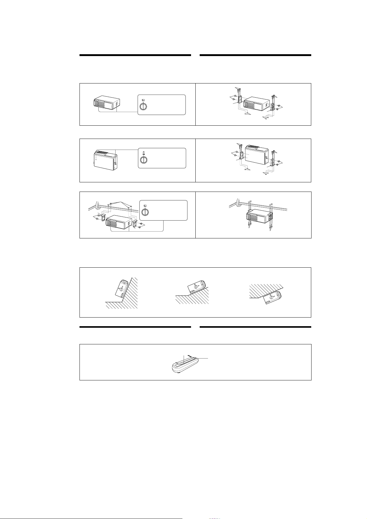
Installation
How to install the CD changer
•When you install the CD changer, be careful not to damage wiring or equipment on the other side of the
mounting surface.
•The brackets 1 provide two positions for mounting, high and low. Use the appropriate screw holes
according to your preference.
Installation
Installation du changeur de CD
•Quand vous installez le changeur de CD, veillez à ne pas endommager les câbles ou les instruments qui
se trouvent de l’autre côté.
•Les supports 1 offrent deux positions de montage, haut et bas. Utilisez les trous de vissage appropriés
en fonction de vos préférences.
Horizontal installation Installation horizontale
1
HORIZONTAL
Align with the marked position.
Alignez sur le repère.
Vertical installation
1
VERTICAL
Align with the marked position.
Alignez sur le repère.
Suspended installation
5
/
32
in.)
ø 3.5 mm (
1
1
2
When the unit is to be installed under the rear tray or in the trunk, observe the following.
•Choose the mounting location carefully so that the unit can be installed horizontally.
•Make sure the unit does not hinder the action of the torsion bar spring, hinge, etc. of the deck lid.
ø 3,5 mm (
5
/
32
po.)
HORIZONTAL
Align with the marked position.
Alignez sur le repère.
2
1
2
Installation verticale
2
Installation suspendue
2
Si vous comptez installer le changeur de CD sous la plage arrière ou dans le coffre, prenez les précautions
suivantes.
•Choisissez soigneusement l’emplacement pour que le changeur soit à l’horizontale.
•Assurez-vous que l’appareil n’entrave pas l’action du ressort à barre de torsion, des charnières, etc., du
couvercle de la malle.
3
2
1
2
1
Inclined installation Installation inclinée
After installing the unit, align the dials with one of the marks so the arrow comes as close to a
vertical position as possible.
Après avoir installé l’appareil, alignez les disques sur l’un des repères afin que la flèche soit aussi
proche que possible de la position verticale.
3
2
ø 3.5 mm
5
(
/
32
in.)
ø 3,5 mm
5
(
/
32
po.)
1
3
3
1
ø 3.5 mm
5
(
/
32
in.)
ø 3,5 mm
5
(
/
32
po.)
3
2
3
V
E
R
T
IC
L
A
L
A
T
N
O
Z
I
R
O
H
Note
Be sure to align the left and right dials with the same mark.
Installing the wired remote
Use the supplied double-sided adhesive tape 4, and mount the wired remote in a suitable location where
it will not interfere with your driving.
4
V
HORIZONTAL
E
R
T
IC
A
L
NTAL
V
HORIZO
E
R
T
I
C
A
L
Remarque
Veillez à aligner les disques gauche et droite sur le même repère.
Installation de la télécommande à fil
Utilisez la bande à double face adhésive fournie 4 pour installer la télécommande à fil dans un endroit
qui ne risque pas de gêner la conduite.
The back of the wired remote
Dos de la télécommande à fil
9
Page 10
CDX-565MXRF
Connections
Caution
•This unit is designed for negative ground 12 V
DC operation only.
•Before making connections, turn the car ignition
off to avoid short circuits.
•Connect the yellow and red power input leads
only after all other leads have been connected.
Reset button
After the installation and connections are completed, after the batteries have been changed, be sure to
press the reset button with a ball-point pen, etc.
•Be sure to connect the red power input lead to the
positive 12 V power terminal which is powered
when the ignition switch is in the accessory
position.
•Run all earth wires to a common earth point.
•When finished making all the connections,
press the reset button of the CD chnager. (See
“Reset button” below.)
•The use of optical instruments with this product
will increase eye hazard.
Reset button
Touche de réinitialisation
Connexions
Précautions
•Cet appareil est uniquement conçu pour
fonctionner sur 12 V CC avec une masse
négative.
•Avant d’effectuer les raccordements, coupez le
contact du véhicule pour éviter tout court-circuit.
•Branchez les fils d‘entrée d‘alimentation jaune et
rouge seulement après avoir terminé tous les
autres branchements.
Touche de réinitialisation
Après avoir terminé l’installation et les connexions ou remplacé les piles, n’oubliez pas d’appuyer sur la
touche de réinitialisation à l’aide d’un stylo à bille, etc.
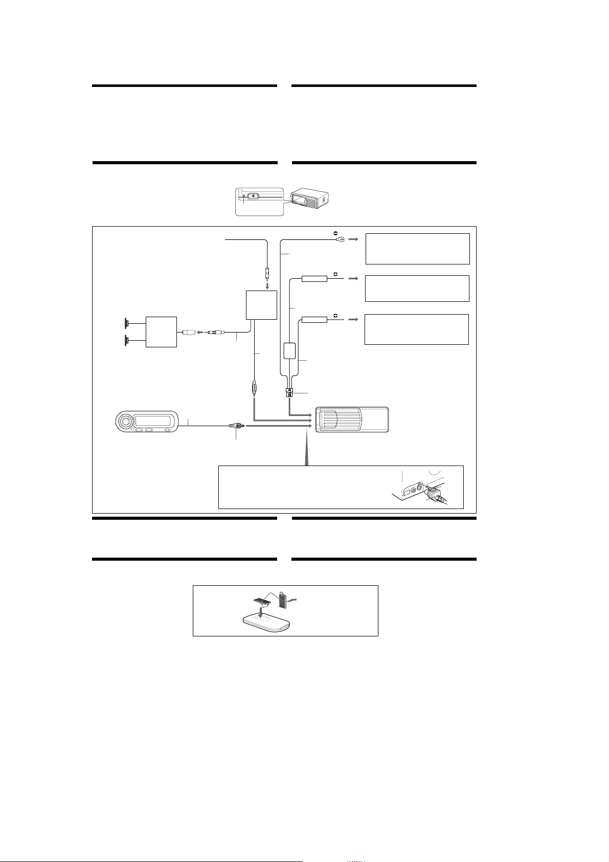
Connection diagram Schéma de connexión
from the car antenna*
Speaker system
Système de
haut-parleurs
* An adaptor (optional) may be necessary for your
car and car audio system. In such a case, consult
your dealer.
* Un adaptateur (en option) peut s’avérer
nécessaire suivant votre voiture et votre
autoradio. En pareil cas, consultez votre
revendeur.
Car audio
Autoradio
depuis l’antenne de la voiture*
Antenna connector
Connecteur d‘antenne
5.5 m
5,5 m
*
1 m
Relay box
Boîtier de relais
7
*
0.5 m
0,5 m
5 m
5 m
Fuse
Fusible
Protection resistor
Résistance de
protection
5 m
6
Black
Noir
Yellow
Jaune
Red
Rouge
•Veillez à raccorder le fil rouge d‘entrée
d‘alimentation à la borne positive de 12 V qui est
alimentée quand la clé de contact est sur la
position accessoire.
•Rassemblez tous les fils de terre en un point
de masse commun.
•Lorsque vous avez terminé toutes les
connexions, appuyez sur la touche de
réinitialisation du changeur de CD. (Voir
“Touche de réinitialisation” ci-après.)
•L’utilisation d’instruments optiques avec cet
appareil accroît les risques de blessures aux yeux.
to a metal point on the car
First connect the black earth lead, then connect the yellow
and red power input leads.
vers un point métallique de la voiture
Branchez d’abord le fil de masse noir et, ensuite, les fils
d’entrée d’alimentation jaune et rouge.
to the +12 V power terminal which is powered at all times
Be sure to connect the black earth lead first.
à la borne d’alimentation +12 V qui est alimentée en
permanence
Raccordez d’abord le fil de masse noir.
to the +12 V power terminal which is powered when the
ignition key switch is in the accessory position
Be sure to connect the black earth lead first.
à la borne d’alimentation de +12 V qui est alimentée quand
la clé de contact est sur la position accessoire
Raccordez d’abord le fil de masse noir.
Wired Remote
Télécommande à fil
RM-X83RF
Insert the connector until it locks.
Insérez le connecteur jusqu’à ce
qu’il s’enclenche.
WARNING
•Plug the connector into the jack on the
left side of the CD changer. Make sure
that the catch of the connector is
secured in the hole next to the jack.
•After inserting the connector, pull the
connector lightly to make sure that it
is locked.
Fuse replacement
If the fuse blows, check the power connection and
replace the fuse. If the fuse blows again after
replacement, there may be an internal malfunction.
Installing the wireless remote
Use the supplied hook and loop fastener 5, and mount the wireless remote in a suitable location where it
will not interfere with your driving.
Warning
Use a fuse with the specified amperage rating.
Use of a higher amperage fuse may cause serious
damage.
CD changer
Changeur de CD
AVERTISSEMENT
•Branchez le connecteur sur la prise du côté
gauche du changeur de CD. Assurez-vous
que l’ergot du connecteur s’adapte dans
l’orifice à côté de la prise.
•Après l’avoir branché, tirez légèrement sur
le connecteur pour vous assurer qu’il est
bien enclenché.
Connector
Connecterur
Remplacement du fusible
Si le fusible saute, vérifiez la connexion
d’alimentation et remplacez-le. Si le fusible saute à
nouveau quand vous venez de le remplacer, il
s’agit peut être d’un mauvais fonctionnement
interne.
Installation de la télécommande sans fil
Utilisez les bandes adhésives 5 pour installer la télécommande sans fil dans un endroit qui ne risque pas
de gêner la conduite.
5
to where it is going to be mounted
vers la surface de montage
Avertissement
Utilisez un fusible de l’ampérage spécifié.
L’utilisation d’un fusible d’ampérage supérieur
peut causer de sérieux dommages.
Catch
Ergot
10
Page 11
SECTION 2
DISASSEMBLY
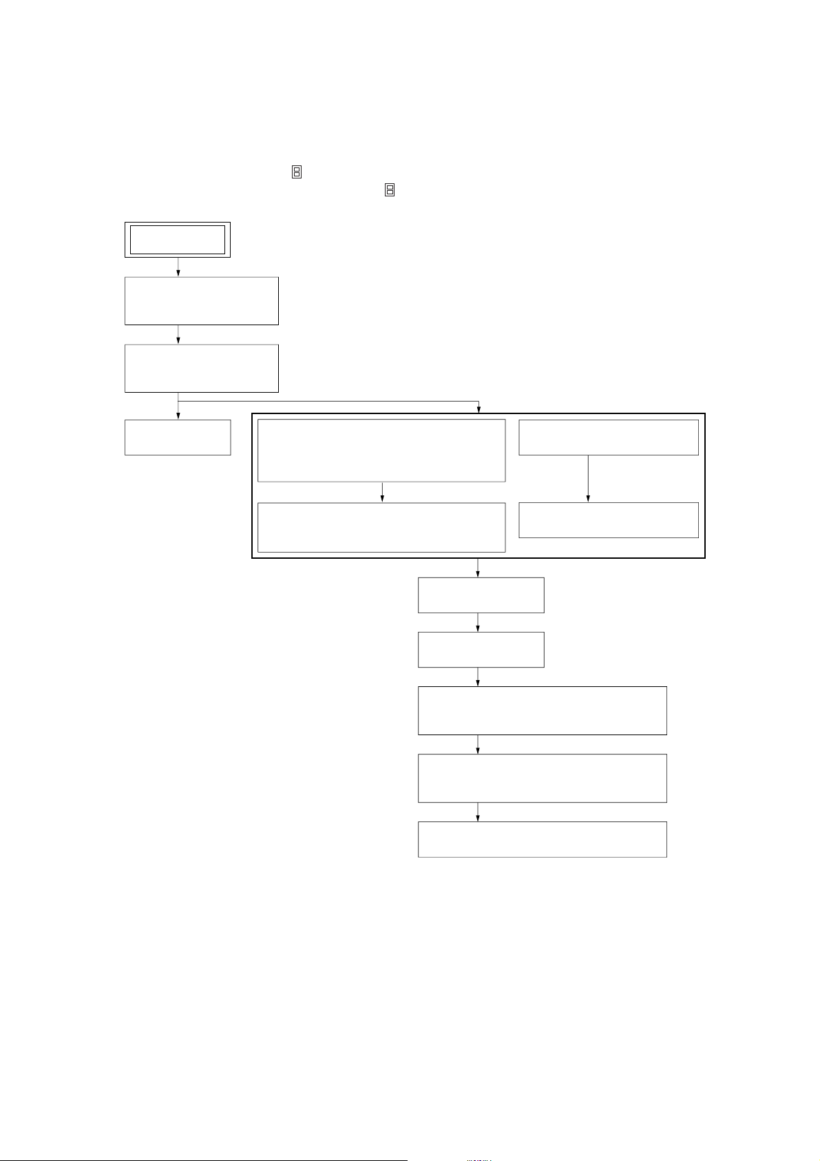
• This set can be disassembled in the order shown below.
2-1. DISASSEMBLY FLOW
Note 1: The process described in can be performed in any order.
Note 2: Without completing the process described in , the next process can not be performed.
SET
2-2. CASE (UPPER.T),
FRONT PANEL ASSY
(Page 12)
2-3. MECHANISM DECK
(MG-251B-137)
(Page 12)
CDX-565MXRF
2-4. FM BOARD
(Page 13)
2-5. MAIN BOARD,
SLIDE VARIABLE RESISTOR
(ELEVATOR HEIGHT SENSOR) (RV202)
(Page 13)
2-6. ELJ MOTOR ASSY
(ELEVATOR) (M104)
(Page 14)
2-9. CHASSIS ASSY
2-10. RF BOARD
2-11. SLED MOTOR ASSY (251) (M101),
2-12. LSW BOARD,
2-7. ESCUTCHEON (T)
(Page 14)
2-8. CHASSIS (U.S) SUB ASSY
(Page 15)
(Page 15)
(Page 16)
OPTICAL PICK-UP (KSS-720A)
(Page 16)
SPINDLE MOTOR (S) SUB ASSY (M102)
(Page 17)
2-13. ELJ MOTOR ASSY (CHUCKING) (M103)
(Page 17)
11
Page 12
CDX-565MXRF
)
)
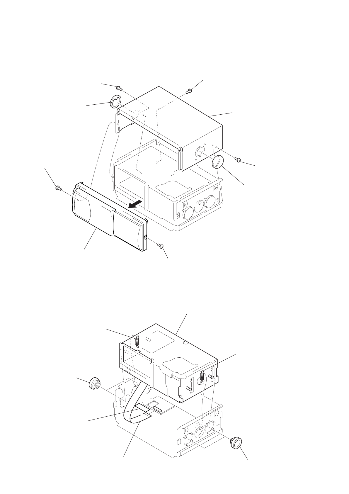
Note: Follow the disassembly procedure in the numerical order given.
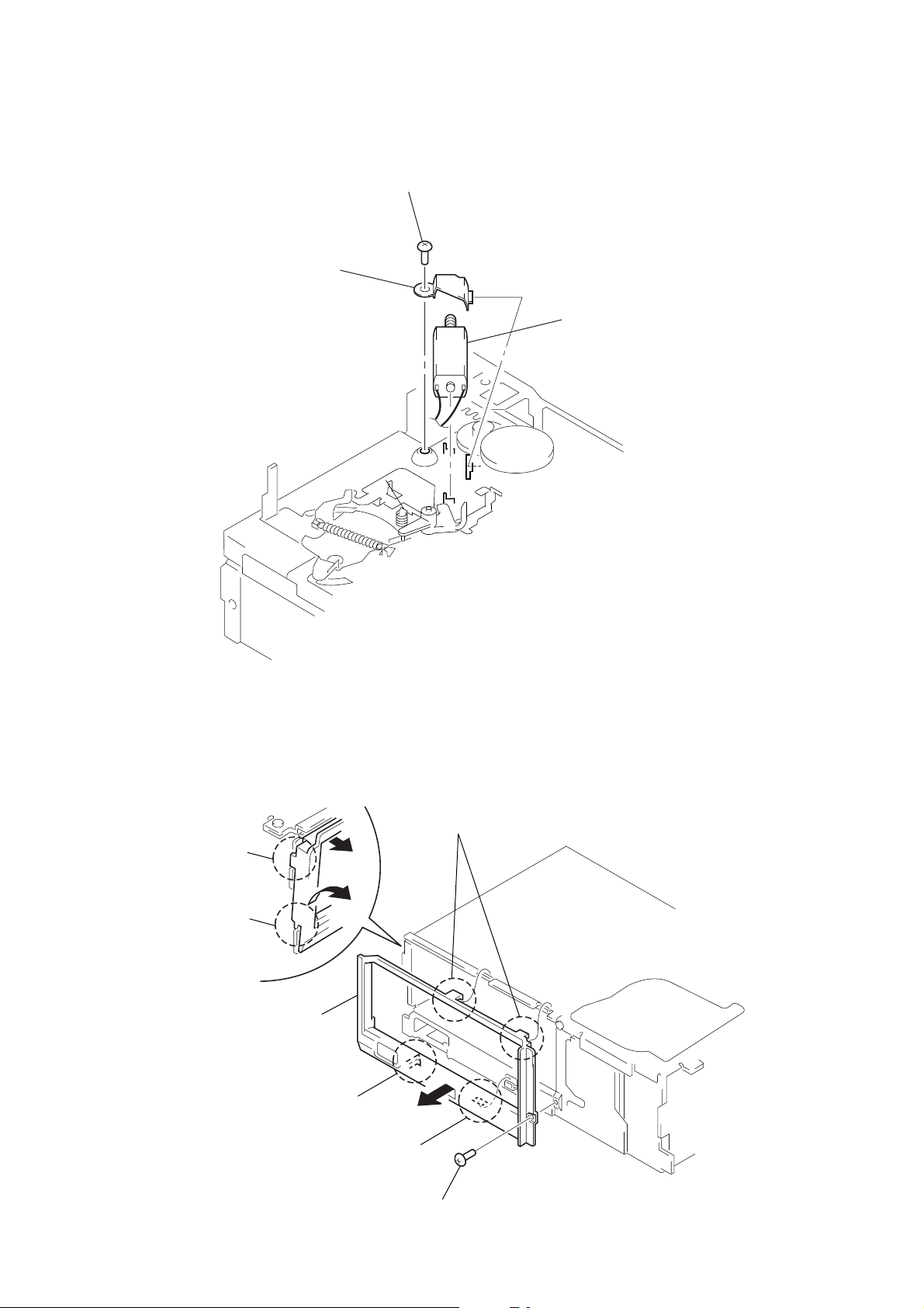
2-2. CASE (UPPER. T), FRONT PANEL ASSY
3
1
screw
(PTT2.6
4
lever (FLT. 838)
×
6)
screw
(PTT2.6
×
6)
3
screw (PTT2.6 × 6)
5
case (upper. T)
3
screw (PTT2.6 × 6
2
front panel assy
2-3. MECHANISM DECK (MG-251B-137)
2
tension coil spring (FL)
1
screw (PTT2.6 × 6)
4
mechanism deck (MG-251B-137)
4
lever (FLT. 838)
2
tension coil spring (FL
12
1
two dampers (T)
filament tape
3
FM flexible board
(CN701)
1
two dampers (T)
Page 13
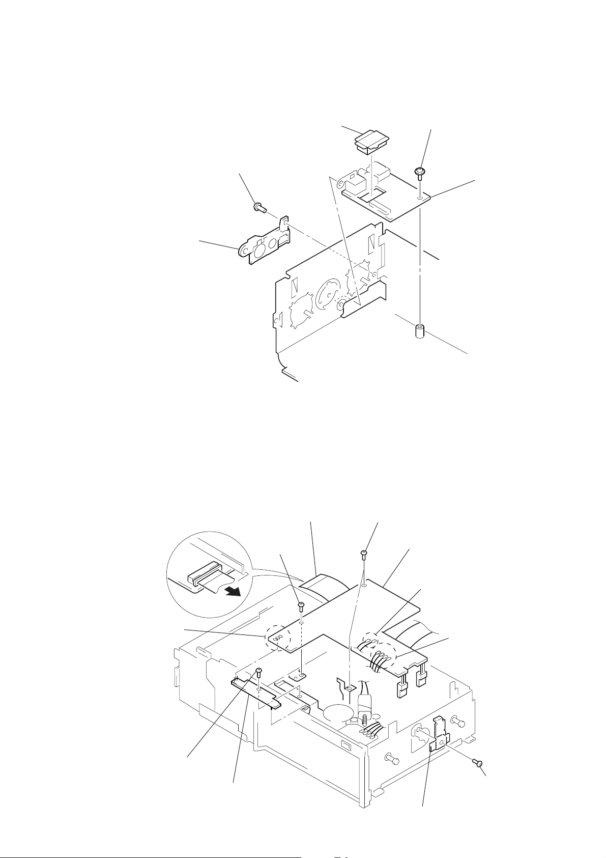
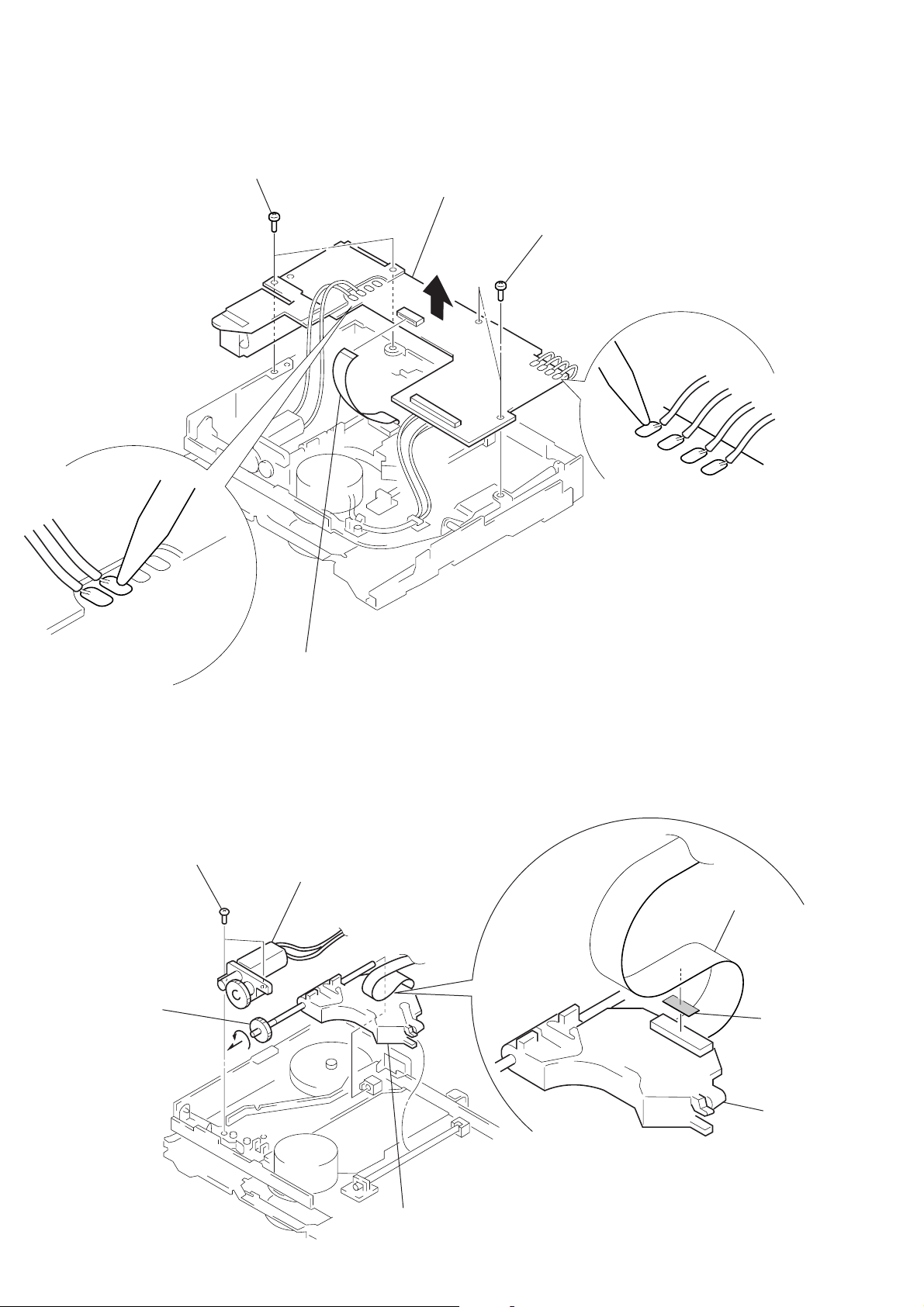
2-4. FM BOARD
d
3
cover
(FM connector.T)
1
screw
(BVTT2.6
CDX-565MXRF
2
4
cover (FM)
×
6)
screw
(ground)
5
FM boar
2-5. MAIN BOARD, SLIDE VARIABLE RESISTOR (ELEVATOR HEIGHT SENSOR) (RV202)
1
main flexible board
2
Remove three solders
of the slide variable resistor
(RV202).
7
screw
(PTT2
(CNJ101)
5
screw (FP)
×
4)
8
slide variable resistor
(elevator height sensor)
(RV202)
5
two screws (FP)
6
main board
2
Remove two solders of
the elevator motor leads (M104).
2
Remove four solders of
the SW board leads.
3
screw (PTT2 × 4)
4
heat sink (T)
13
Page 14
CDX-565MXRF
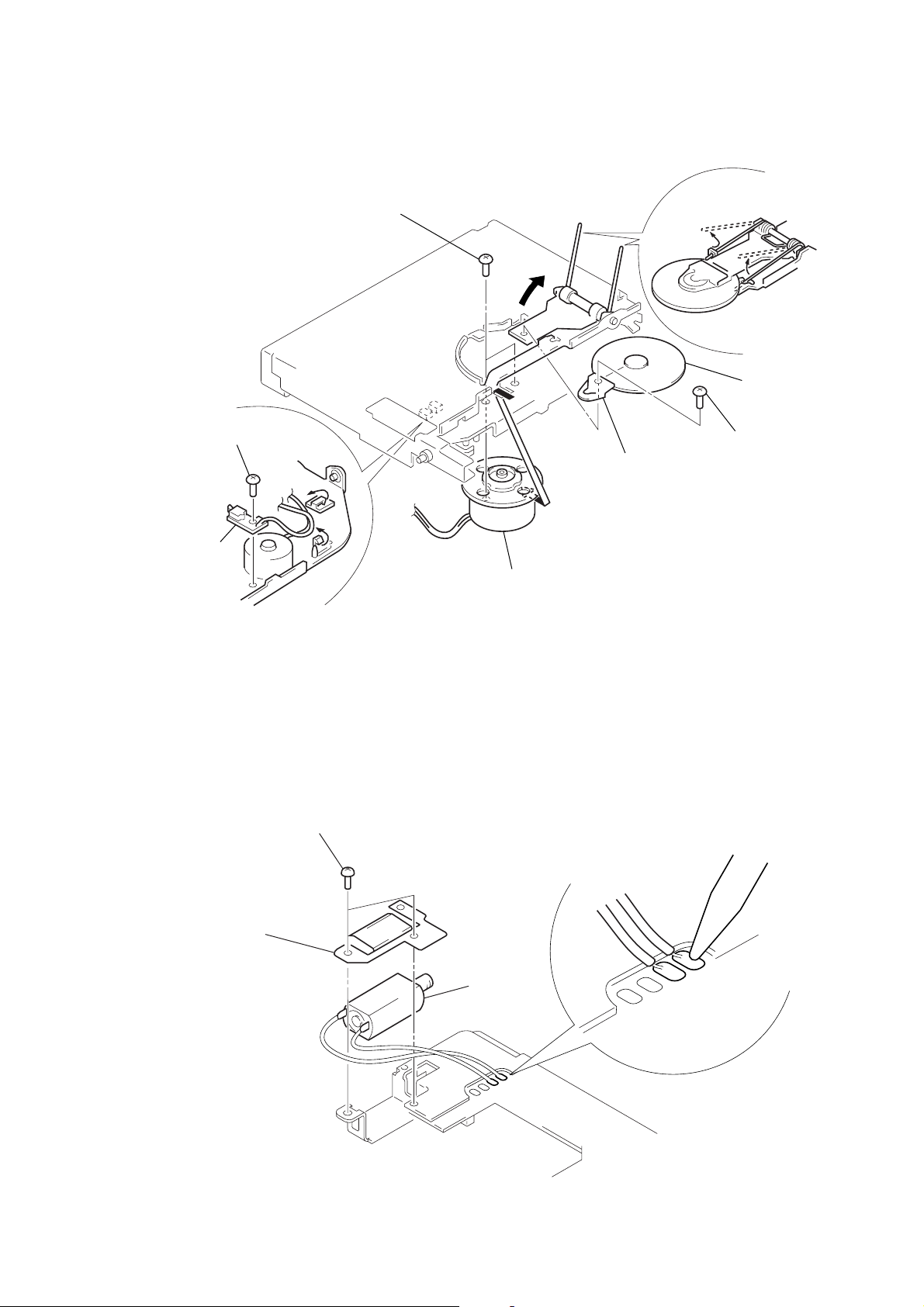
2-6. ELJ MOTOR ASSY (ELEVATOR) (M104)
1
2
bracket (EVM.S)
screw
(PTT2
×
4)
3
ELJ motor assy (elevator) (M104)
2-7. ESCUTCHEON (T)
2
Remove the claw
in the direction of arrow
4
Remove the ditch
in the direction of arrow
Remove the escutcheon (T)
5
in the direction of arrow
A
B
3
two claws
.
.
C
.
3
claw
A
B
4
C
ditch
14
1
screw (T)
Page 15
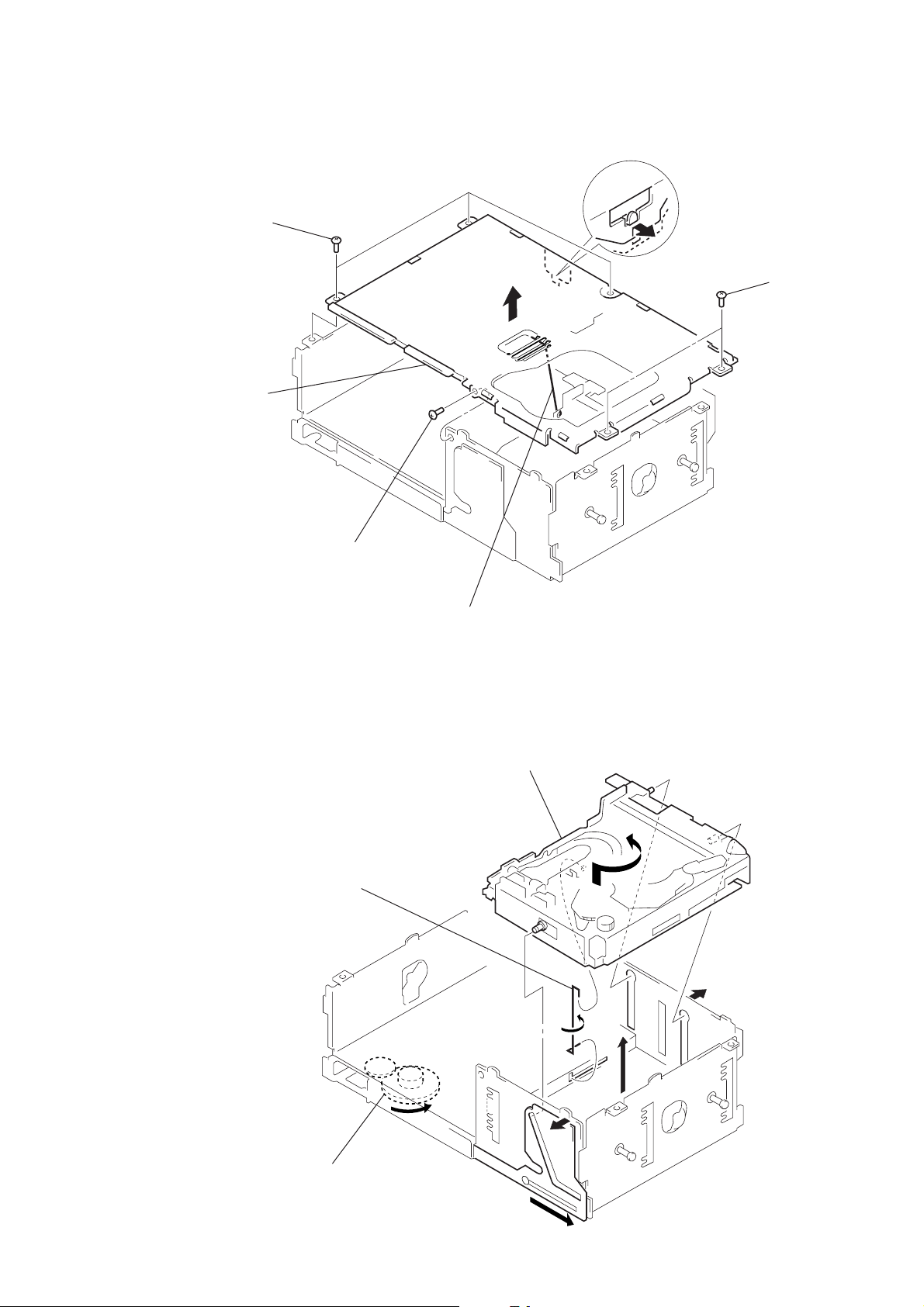
2-8. CHASSIS (U.S) SUB ASSY
1
three screws
(PTT2 × 4)
5
chassis (U.S) sub assy
3
A
CDX-565MXRF
2
Remove the edge
in the direction
of arrow A.
1
two screws
(PTT2 × 4)
2-9. CHASSIS ASSY
1
screw
(PTT2 × 4)
5
spring (stopper.lower)
4
spring (SUT)
6
chassis assy
4
3
1
Turn the gear (EVD.S) fully
in the direction of arrow
A
2
A
3
.
15
Page 16
CDX-565MXRF
2-10. RF BOARD
3
two screws
(PTT2
×
4)
4
RF board
3
two screws
×
4)
(PTT2
2
Remove two solders
of the sled motor leads
(M101).
1
OP flexible board (CN102).
2-11. SLED MOTOR ASSY (251) (M101), OPTICAL PICK-UP (KSS-720A)
1
two precision screws
(P2
×
3)
2
sled motor assy (251)
(M101)
2
Remove four solders
of the LSW board leads
and spindle motor leads (M102).
OP flexible board
4
Turn shaft (feed) assy
in the direction
of the arrow,
then remove it.
16
3
optical pick-up
(KSS-720A)
adhesive
sheet
optical
pick-up
Note: After connecting OP flexible board,
fix it with adhesive sheet
to optical pick-up.
Page 17
2-12. LSW BOARD, SPINDLE MOTOR (S) SUB ASSY (M102)
)
w
8
two precision screws
×
2.2)
(P1.7
7
1
precision screw
(P2
×
2.5)
5
bracket (CP)
CDX-565MXRF
3
spring (chucking)
6
retainer (disc
4
precision scre
(P2 × 2.2)
2
LSW board
2-13. ELJ MOTOR ASSY (CHUCKING) (M103)
2
two screws
×
4)
(PTT2
3
retainer (CHM)
4
ELJ motor assy (chucking) (M103)
9
Remove the spindle motor (S) sub assy (M102)
in the direction of the arrow.
1
Remove two solders of
the chucking motor leads (M103).
17
Page 18

CDX-565MXRF
)
• This set can be assembled in the order shown below.
3-1. ASSEMBLY FLOW
3-2. OPTICAL PICK-UP COMPLETE ASSY
(Page 18)
3-3. GEAR (LOMINI) / (LOAD 1) ASSY
(Page 19)
3-4. OPERATION CHECK
(Page 19)
SECTION 3
ASSEMBLY
3-2. OPTICAL PICK-UP COMPLETE ASSY
1
chuck plate
Move the lever (LOCK 3A) in the direction of arrow A,
and return it a little in the direction of arrow
from the position where the chuck plate is moved
down to the lower limit.
B
A
B
3
stop ring 2.0 (E type
4
tension spring (DH)
18
shaft (A)
2
optical pick-up complete assy
Note: Insert the shaft (A) first.
Page 19

3-3. GEAR (LOMINI)/(LOAD 1) ASSY
CDX-565MXRF
gear (LOAD 2)
marking
Fig. A
3
Attach the gear (LOAD 1) assy
with its facing inside.
gear (LOMINI)
slit
chuck plate
2
Attach the gear (LOMINI) at the position
shown in Fig. A.
shaft (rotary prevention C)
1
B
stop ring 1.5 (E type)
4
Move the lever (LOCK 3A)
fully in the direction of arrow
to move the chuck plate up.
B
3-4. OPERATION CHECK
1
Confirm that the slider moves in the direction of arrow C to move down
the chuck plate if the gear (LOAD 1) is rotated in the direction of arrow
or the chuck plate moves up and the slider mov es in the direction of arrow
D
if the gear is rotated in the direction of arrow B.
chuck plate
A
slider
D
C
A
gear (LOAD 1) assy
B
19
Page 20

CDX-565MXRF
SECTION 4
MECHANICAL ADJUSTMENT
ELEVATOR HEIGHT (ADDRESS) ADJUSTMENT
Note: This adjustments is necessary when the system controller (IC201),
variable resistor (RV201), slider (R), slider (L), or chassis (ELV)
was replaced for any repair.
Connection:
power supply
(DC 14.4 V)
+
GND
POWER connector (CN303)
wired remote commander
(RM-X83RF)
compact disc changer
DISPLAY connector (CN302)
Adjustment Method:
Note: Perform following the adjustment by the wired remote commander
(RM-X83RF).
1. Load a disc magazine, and place the set vertically as shown
below.
2. Connect the regulated power supply, and turn the power on.
3. Select DISC 5.
4. At this time, if the elevator shaft does not position between
comb teeth A and B at addresses 5 and 6 as shown below,
adjust the following.
5. Select DISC 5 and DISC 6 alternately , so that the ele vator shafts
moves from address 6 to address 5, or from 5 to 6. At this
time, adjust R V201 on the main board so that the eleva tor shaft
positions smoothly between comb teeth A and B.
6. Further, place the set horizontally and make same adjustment
as mentioned above.
7. After adjustment at addresses 5 to 6 is finished, check all operations from addresses 1 to 10 with the set placed vertically
and horizontally respectively to confirm that the ele vator shaft
positions in a range between comb teeth A to B.
comb tooth at address 6
comb tooth at address 5
comb tooth at address 6
elevator shaft
A
B
OK NG
A
elevator shaft
B
comb tooth at address 5
20
RV201
Page 21

SECTION 5
ELECTRICAL CHECK
CDX-565MXRF
Note:
1. This adjustment is performed with the set placed horizontally.
2. Power supply voltage: DC14.4 V (more than 3 A).
3. Be sure to use the disc “YEDS-18” parts code: 3-702-101-01, but only
when indicated.
Connection:
power supply
(DC 14.4 V)
+
GND
POWER connector (CN303)
wired remote commander
(RM-X83RF)
FOCUS BIAS CHECK
Connection:
– RF Board (Component Side) –
oscilloscope
(AC range)
+
–
TP (RFAC)
TP (VC)
IC101
TRACKING OFFSET CHECK
Connection:
– RF Board (Component Side) –
oscilloscope
(DC range)
+
–
TP (VC)
IC101
TP (TE)
compact disc changer
DISPLAY connector (CN302)
Procedure:
1. Connect the oscilloscope to TP (RFAC) and TP (VC) on the
RF board.
2. Put the set into play mode by loading the disc (YEDS-18).
3. Conf irm that oscilloscope wav eform is clear and check RF signal level is correct or not.
Note:
Clear RF signal waveform means that the shape “ ◊” can be clearly distinguished at the center of the waveform.
RF signal waveform
VOLT/DIV: 200 mV
TIME/DIV: 500 ns
(10 : 1 probe in use)
level: 1.4 ± 0.3 Vp-p
When observing the eye pattern, set the oscilloscope to AC range
and raise the vertical sensitivity so that it may be easily seen.
Procedure:
1. Connect the oscilloscope to TP (TE) and TP (VC) on the RF
board.
2. Put the set into play mode by loading the disc (YEDS-18).
3. Rotate the
[ AMS ] dial on the wired remote commander,
.
>
and check the traverse waveform*.
4. Confirm that the oscilloscope waveform is symmetrical on the
top and bottom in relation to 0 V dc, and check this level.
* Traverse waveform: This is the tracking error wave form appears
when crossing the track.
Traverse waveform
A
0 V
B
A=B
traverse waveform
(100 track jump waveform)
VOLT/DIV: 500 mV
TIME/DIV: 2 ms
Center: 0 V
2121
Page 22

CDX-565MXRF
6-1. BLOCK DIAGRAM – SERVO Section –
RF AMP,
DETECTOR
A
B
C
D
E
F
LASER DIODE
OPTICAL
PICK-UP BLOCK
(KSS-720A)
(TRACKING)
(FOCUS)
I-V AMP
PD LD
VC
2-AXIS DEVICE
A
6
B
7
C
8
D
9
E
10
F
11
AUTOMATIC
POWER
CONTROL
M101
(SLED)
M102
(SPINDLE)
M103
(CHUHCKING)
FOCUS/TRACKING ERROR AMP
Q101
IC101
RFAC
SUMMING
AMP
RFDC
SUMMING
AMP
FOCUS
ERROR
AMP
TRACKING
ERROR
AMP
LD
1
27
VC
TRACKING/FOCUS COIL DRIVE,
SLED/SPINDLE/CHUCKING
VO3 +
8
VO3 –
9
VO4 +
6
VO4 –
7
VO2 +
10
MM
MM
MM
VO2 –
11
VO1 +
12
VO1 –
13
VL0 +
5
VL0 –
4
AC
SUM
4 3
RW/ROM
RW/ROM
APC AMP
MOTOR DRIVE
IC201
MOTOR
COIL
DRIVE
DRIVE
COIL
DRIVE
MOTOR
DRIVE
MOTOR
DRIVE
MOTOR
DRIVE
DC OFST
SW
PD
DVC
VIN3 +
VIN3 –
VIN4 +
VIN4 –
VIN2 +
VIN2 –
VIN1-B
FWD
REV
RFDCO
12
2
14
EQ IN
FE
TE
25
24
31
32
22
21
18
1
2
28
30
16
18
SECTION 6
DIAGRAMS
RFAC
VCA
RF
FE
TE
48
49
50
51
46
47
43
RFAC
RF EQ
AMP
RF AMP OFFSET
CONTROL SWITCH
Q102
5963
VC
TFDR
TRDR
FFDR
FRDR
PWM GENERATOR
SFDR
SRDR
MDP
DIGITAL
15
D-RAM
IC102
CE
CLV
RF
RFDC
OP AMP
ANALOG SW
A/D CONVERTER
SERVO DSP
71
73
74
DQ1 – DQ4
A0 – A10
RAS
CAS
WE
OE
FE
TE
FE
TE
5
23
4
22
RFAC
ASYMMETRY
CORRECTOR
ASYI
ASYO
2, 3,
24, 25
21, 8
9 – 12, 15 – 19,
61606258
SE
MIRR
DECT
FOK
FILTER
66 69 68 67
FILI
PCO
FILO
CLTV
DIGITAL
PLL
D0 – D3
118, 117
116, 115,
A0 – A10
3 – 1, 111
109 – 106, 7 – 5,
XRAS
113
XCAS
119
XWE
114
XOE
120
ON : When completion of the disc
ON : When completion of the disc
chucking operation
chucking operation
ON : When completion of the disc
ON : When completion of the disc
save operation
save operation
VIBRATION
MEMORY
CONTROLLER
&
COMPRESSION
EXPANDER
XRDE
XWRE
XQOK
ON : When the optical pick-up
ON : When the optical pick-up
is inner position
is inner position
EFM
DEMODULATOR
(CHUCKING END DETECT)
INTERNAL BUS
SUBCODE
PROCESSOR
SW3
(LIMIT)
SW1
SW2
(SAVE END DETECT)
D/A
INTERFACE
32k RAM
ERROR
CORRECTOR
CPU
INTERFACE
SERVO AUTO
SEQUENSOR
SERVO
INTERFACE
SSTP
45
WDCK
GFS
DATA
CLOK
XLAT
SENS
SQSO
SQCK
SCOR
XRDE
XWRE
XQOK
SCLK
FOK
XRST
SDI
BCK
LRCK
DOUT
DIGITAL
OUT
SELECTOR
1578
1581
1523
1525
1524
1526
1514
1515
1517
159
158
1512
27
35
21
D201
1585
PCMD
15
88
1588
BCK
15
90
LRCK
15
86
CD-ROM/RW
SELECT SWITCH
Q202
PCMDI
15881589
BCKI
151591
LRCKI
87
DIGITAL SIGNAL PROCESSOR,
DIGITAL SERVO PROCESSOR,
D-RAM CONTROLLER
IC101
R/RW SEL
90
GRSCOR
40
GFS
5
10
CDDAT
CDCLK
8
CDLAT
9
SENS
7
SQSO
84
SQCK
85
SCOR
38
XRDE
16
XWRE
17
XQOK
15
SYSTEM CONTROLLER
IC201 (1/3)
SCLK
6
FOK
4
XRST
11
LOADF
95
LOADR
96
LIM SW
100
D/A
CONVERTER
LOW-PASS
FILTER
AOUT1
15881599
AOUT2
102
SIGNAL PATH
FILTER
CLOCK
XTAI
93 94
X101
XTAO
LOUT1
LOUT2
97
104
AIN1
15881598
LOW-PASS
AIN2
103
GENERATOR
16.9344MHz
SDO
L
R
XTAL-IN
TCXRDE
A
(Page 23)
B
(Page 23)
C
(Page 23)
D
(Page 23)
E
(Page 23)
: CD PLAY
LOAD SW
98
SAVE SW
99
2222
Page 23

6-2. BLOCK DIAGRAM – MAIN Section (1/2) –
L
(Page 22)
C
R
ISOLATOR
IC401
MUTING
Q410, 420
MUTING CONTROL
SWITCH
Q402
X701
7.6MHz
22
1
14
13
LIN
RIN
XIN
XOUT
PRE-EMPHASIS
& LIMITER
PRE-EMPHASIS
& LIMITER
L. P. F.
L. P. F.
RV701
TRANSMITTER
MODULATION
5
SENSITIVITY
FM STEREO
TRANSMITTER
BUFFER, AMP
Q701, 702
IC701
MPX
MUTING OSC
MPX
OSC
ADJ
MUT
18
CDX-565MXRF
RF IN
9 11
PD
7
PHASE
DETECTOR
17
RF AMP
PROGRAM
COUNTER
SHIFT
REGISTER
DATA
CLK
16
RF OUT
CE
15
CN703
OUTPUT
L. P. F.
(Page 22)
(Page 22)
(Page 22)
(Page 22)
SDO
B
IC605
SDI
BCK
A
LRCK
XTAL-IN
D
TCXRDE
E
9 SDO
12 SDIO
13 BCKIA
14 LRCKIA
62 X1
63 X0
60 XRDE
CD-ROM DECODER
MP3 DECODER
IC601
REQ19STANBY1RESET5I2C SDA6I2C SCL
39
IC604
AD16
−
AD0
51,
−
55
IO7
−
−
53
IO0
46, 47, 49
31, 41,
−
42, 45, 44
36, 34
−
3, 4, 7, 10, 11, 15,
38
16CE
43WR
17OE
29
−
IO8
−
23, 25
IO1
−
21
S-RAM
IC602
A16
−
A0
13, 3, 2, 31, 1,
−
12, 4, 11, 7, 10
20
30 CS1
5WE
32 OE
10 128
BUS BUFFER
IC302 (1/2)
11 139
SIGNAL PATH
: CD PLAY
73
3
2
80
SDA
81
SCL
SYSTEM CONTROLLER
IC201 (2/3)
87
PLLDATA
89 88
PLLCLK
PLLCE
26
MUTE
DECINT
DECSTBY
DECXRST
2323
Page 24

CDX-565MXRF
6-3. BLOCK DIAGRAM – MAIN Section (2/2) –
KEYA/D
ENCODER1
ENCODER2
LCDDATA
LCDCLK
LCDCE
SIRCS
POWER ON
CN302
DISPLAY
8
6
1
5
4
3
7
2
M104
(ELEVATOR)
B. UP+3.3V
LCD +5V
M
2
6
4
BUS BUFFER
IC302 (2/2)
ON : When magazine
is set
ELEVATOR
MOTOR DRIVE
IC301
OUT1
9
MOTOR
OUT2
7
KEY ACTIVE
SWITCH
DRIVE
Q205
D202
1
5
3
SW301
SW201
MAGAZINE
DETECT
IN1
3
IN2
4
X201
12.288MHz
SYSTEM CONTROLLER
72
MGLK-SW
ELVF
36
37
ELVR
65
EXTAL
63
XTAL
78 KEYACK
39
KEYON
49
KEYIN
47
ENCODER1
48
ENCODER2
34
LCDDATA
LCDCLK
33
35
LCDCE
41
SIRCS
EJECT
75
IC201 (3/3)
ACCIN
MCK
EHS
VREF
ELVON
BUCHK
RES
LCDON
CDON
CN303
POWER
ACCESSORY
91
RV201
BATTERY
CHECK
Q301, 305
CD-ROM/MP3
DECODER
+2.5V
ELEVATOR HEIGHT
(ADDRESS)
RV202
ELEVATOR HEIGHT
SENSOR
D306
HIGH VOLTAGE
DETECT
Q302
SW302
(RESET)
B. UP
+3.3V
D301
RESET SIGNAL
GENERATOR
IC303
+2.5V
REGULATOR
IC603
SERVO +3.3V
DRIVER +8V
LCD +5V
+3.3V
REGULATOR
IC306
SERVO +5V
52
50
53
30
92
59
28
D203
29
CHECK
Q308
+8V
REGULATOR
IC304
+3.3V
REGULATOR
Q303, 304
+5V
REGULATOR
IC304
+5V
REGULATOR
IC305
D302
3
ACC
2
B. UP
2424
Page 25

CDX-565MXRF
d
6-4. NOTE FOR PRINTED WIRING BOARDS AND SCHEMATIC DIAGRAMS
Note on Printed Wiring Board:
• X : parts extracted from the component side.
• Y : parts extracted from the conductor side.
f
•
• : Pattern from the side which enables seeing.
(The other layers' patterns are not indicated.)
Caution:
Pattern face side: Parts on the pattern face side seen from
(Conductor Side) the pattern face are indicated.
Parts face side: Parts on the par ts face side seen from
(Component Side) the parts face are indicated.
: internal component.
Note on Schematic Diagram:
• All capacitors are in µF unless otherwise noted. pF: µµF
50 WV or less are not indicated except for electrolytics
and tantalums.
• All resistors are in Ω and 1/
specified.
•%: indicates tolerance.
f
•
• C : panel designation.
• A : B+ Line.
• H : adjustment for repair.
•Power voltage is dc 14.4V and fed with regulated dc power
•Voltages and waveforms are dc with respect to ground in
•Voltages are taken with a V OM (Input impedance 10 MΩ).
•Waveforms are taken with a oscilloscope.
• Circled numbers refer to waveforms.
• Signal path.
: internal component.
Note:
The components identified by mark 0 or dotted
line with mark 0 are critical for safety.
Replace only with part
number specified.
supply from ACC and BATT cords.
CD play mode.
no mark : CD PLAY
Voltage variations may be noted due to normal production tolerances.
Voltage variations may be noted due to normal production tolerances.
J : CD PLAY
: Impossible to measure
∗
4
Note:
Les composants identifiés par
une marque 0 sont critiques
pour la sécurité.
Ne les remplacer que par une
pièce portant le numéro
spécifié.
• Circuit Boards Location
W or less unless otherwise
FM board
MAIN board
EJECT board
RF boar
LSW board
2525
Page 26

CDX-565MXRF
6-5. PRINTED WIRING BOARDS – RF/LSW Boards – • See page 25 for Circuit Boards Location.
• Semiconductor
Location
Ref. No. Location
IC101 H-6
IC201 J-5
Q101 F-7
Q102 H-7
1
2 3 4 5 6 7 8 9 10 11 12 13
A
SW2
B
SW1
CHUKING
END DETECT
SAVE END
DETECT
C
TP106
TP105
TP103
TP104
WHT
YEL
RED
BLK
D
M101
M
(SLED)
E
M103
M
(CHUKING)
F
G
OPTICAL
PICK-UP
BLOCK
(KSS-720A)
OP FLEXIBLE
BOARD
CN102
R103
H
C107
TP
TP
(VC)
(RFAC)
R223
R222
R220
R104
C106
R106
C209
R215
R218
C202
IC201
R219
SW3
MAIN FLEXIBLE
1-679-422-
BOARD
12
(12)
CNJ101
R214
R212
R210
R208
R206
R204
R201
R213
R211
R209
R207
R205
R203
R202
C208
C207
C206
C205
C204
C203
C217
I
A
MAIN BOARD
CN101
J
K
(Page 28)
LSW BOARD
BLU
(LIMIT)
YEL
R102
IC101
TP
(TE)
R107
C109
R108
R216
R109
C103
R110
C111
Q101
C101
R117
C102
R105
R111
R122
R113
R116
TP107
TP108
TP102
TP101
R101
Q102
R121
R120
R112
1-679-421-
C108
C104
C122
YEL
BLU
BLK
RED
(12)
M102
M
(SPINDLE)
12
C121
C105
C201
1-679-421-
12
(12)
2626
Page 27

6-6. SCHEMATIC DIAGRAM – RF/LSW Boards – • See page 33 for Waveforms. • See page 36 for IC Block Diagrams.
Q101
MSB709
-RT1
Q102
MUN2212T1
CDX-565MXRF
MAIN
BOARD
CN101
(1/3)
(Page 30)
The components identified by mark 0 or dotted
line with mark 0 are critical for safety.
2727
Replace only with part number specified.
Les composants identifiés par une marque 0 sont
critiques pour la sécurité. Ne les remplacer que
par une pièce portant le numéro spécifié.
Page 28

CDX-565MXRF
6-7. PRINTED WIRING BOARDS – MAIN Board (Component Side) – • See page 25 for Circuit Boards Location.
• Semiconductor
Location
Ref. No. Location
D201 F-10
D202 G-9
D203 G-9
D301 F-4
D302 E-2
D306 F-4
D310 H-2
IC101 C-9
IC102 E-7
IC201 G-10
IC301 H-3
IC302 F-5
IC303 G-3
IC306 E-6
IC401 B-7
IC601 E-9
IC602 G-7
IC603 G-8
IC604 E-10
IC605 B-8
Q202 E-11
Q205 G-9
Q301 G-4
Q302 G-4
Q303 H-3
Q304 G-2
Q305 G-4
Q402 D-6
Q410 B-6
Q420 C-6
1 2 3 4 5 6 7 8 9 10 11 12
MAIN BOARD
(COMPONENT SIDE)
A
IC605
135
4
B
IC401
C
90
91
IC101
120
130
(Page 34)
FM BOARD
B
D
FM FLEXIBLE BOARD
CN701
1
26
33
IC601
E
13
IC102
14
48
49 64
IC306
61
60
31
1732
16
26
MAIN
FLEXIBLE
BOARD
1
A
RF
BOARD
CNJ101
(Page 26)
54
1
IC604
13
IC302
F
125
26
IC602
G
H
1
2
IC301
4
3
IC303
SW201
MAGAZINE
DETECT
IC603
5
4
1
3
50
IC201
51
100
76
75
I
J
K
11
1-168-744-
(11)
2828
Page 29

6-8. PRINTED WIRING BOARDS – MAIN (Conductor Side)/EJECT Boards – • See page 25 for Circuit Boards Location.
CDX-565MXRF
1 2 3 4 5 6 7 8 9 10 11 12
MAIN BOARD
(CONDUCTOR SIDE)
A
• Semiconductor
Location
Ref. No. Location
D303 F-10
IC304 H-12
IC305 F-12
(CHASSIS)
B
C
D
E
F
TP324
G
TP325
TP331 TP332 TP330
D303
H
RED
BLK
(CHASSIS)
(CHASSIS)
M
M104
(ELEVATOR)
1-168-744-
IC305
IC304
11
(11)
I
RED
WHT
EJECT BOARD
RED
J
RV202
ELEVATOR
K
HEIGHT
SENSOR
(CHASSIS)
TP802 TP803 TP801
(RESET)
11
1-684-746-
(11)
2929
Page 30

CDX-565MXRF
6-9. SCHEMATIC DIAGRAM – MAIN Board (1/3) – • See page 33 for Waveforms. • See page 36 for IC Block Diagram.
(1/3)
CLOK
DATA
XRST
XLAT
R116
C114
1k
0.1
FLEXIBLE
BOARD
(Page 27)
MAIN
CN101
26P
GND
GND
+8V
+8V
MDP
SRDR
SFDR
TRDR
TFDR
FFDR
FRDR
CH.REV
CH.FWD
LIM.SW
LOAD2
LOAD1
SW
VC
FE
TE
RF
RFAC
+5V
+3.3V
GND
GND
TP102
TP104
TP106
TP108
TP110
TP112
TP114
TP116
TP118
TP120
TP122
TP101
TP103
TP105
TP107
TP109
TP111
TP113
TP115
TP117
TP119
TP121
TP123
SCLK
SENS
FOK
C101
0.1
C102
0.1
C103
0.1
R101
MDP
SFDR
SRDR
TFDR
TRDR
FFDR
FRDR
33k
MDP
SRDR
SFDR
TRDR
TFDR
FFDR
FRDR
REV
FWD
LIM
SAVE
LOAD
SW
ZZ1
ZZ2
ZZ3
ZZ4
ZZ1
BP122
BP121
TP126
TP125
R125
R122
33k
C121
220p
33k
C122
220p
C123
0.1
SCOR
SQCK
DIGITAL SIGNAL PROCESSOR,
DIGITAL SERVO PROCESSOR,
D-RAM CONTROLLER
IC101
CXD3027R
SQSO
XQOK
A8
A6
A5
A4
XWRE
XRDE
A9
A7
D0
D1 D2
XWE
XRAS
XOE
XCAS
XWE
XRAS
A10
16.9344MHz
D2
D3
D0
D1
A0
A1
A2
A3
R118
XX1
XX2
XX3
XX4
XX5
XX6
330
X101
A10
A0
A1
A2
A3
C161
0.1
C162
0.1
C113
0.1
C117
100
16V
C112
0.1
R117
220
IC102
GM71VS17403
CLT-6
D-RAM
D3
XCAS
XOE
A9
A8
A7
A6
A5
A4
A1
A2
R123
ZZ2
100k
033
R104
.0
3.3k
0
R103
3.3k
R108
470k
C105
R102
0.047
10k
R109 C115
ZZ3
1M 1
0.0015
C104
106
C
ZZ4
R107
10k
C107R105
220p820k
C111 C108
0.1 0.1
100
C109R106
0.01470k
C110
1
GFS
GRSCOR
R124 R120
100 100
119
R
R121
100
YY3
YY1
YY4
YY2
2
1
B
B
B3
B4
(Page 31)
A3
A4
A5
A6
A7
(Page 32)
3030
Page 31

6-10. SCHEMATIC DIAGRAM – MAIN (2/3)/EJECT Boards – • See page 33 for Waveforms. • See page 36 for IC Block Diagrams.
CDX-565MXRF
Ver 1.1
(Page 30)
(2/3)
DECXRST
GATE SWITCH
G
V
IC605
TC7SH08FU-
TE85R
R615C615
1000.1
C601
0.1
C604
0.1
R601
1k
A0
A1
SDA
A2
A3
A4
A5
CE
RB601
100k
X4
XX1
XX2
XX3
XX4
XX5
XX6
R114
R110C118
R401
12k
12k330p
5.6k
C120R111
1000p12k
R403
5.6k
C124
1000p
R112
12k
R113
12k
R115
R404
12k
C119
330p
5.6k
C116
R402
100
5.6k
16V
YY3
A1
A3
A4
A5
A6
A7
A2
R613
C614
1k
0.1
V
SCL
YY2
YY4
YY1
C401
470p
R405
10k
VCC
R406
10k
C402
470p
ISOLATOR
TLV2362IPWR
GND
RESET
MIMD
AD0
AD1
I2C_SDA
I2C_SCL
AD2
VDDT(3.3V)
SDO
AD3
AD4
SDI0
BCKIA
LRCKIA
AD5
CE
IC401
GATE SWITCH
G
IC604
TC7SH08FU-
TE85R
C602
C608
E
0.1
D
R
-X
R610C609
C
1M0.001
T
X1
X0
VSSX
XRDE
VDDX(2.5V)
ND)
E
VSSL(2.5G
VDD(2.5V)
VSS(2.5GND)
O
STANBY
Y
B
T
S
C
E
E
D
O
C603
R409 R407
10k 10k
R612
100
C610
47
C612
0.1
16V
C616
100p
0.1
C607
0.33
R608
270
270
R607
DP
PDO
VSSP
VCOI
VD
CD-ROM DECODER,
MP3 DECODER
IC601
CXD9684R-004
VDAR(2.5V)
VDAL(2.5V)
LO
VRAL
TP601
TP602 TP301
0.1
C409 R413
10
16V
C403
0.1
C404
100
16V
R408R410
33k10k
C410
10
16V 1K
7
IO
IO7
RO
1K
R414
5
6
IO
IO
IO6
RAR
V
C606
0.1
3
4
IO
IO
IO5
IO4
VDD(2.5V)
VSSR(2.5GND)
CKS
TESTP
2
1
A
C411 R415
100p 100k
C412 R416
100p 100k
IO3
VDDT(3.3V)
AD12
2
IO
IO2
VSS
IO1
IO0
AD15
AD16
WR
AD14
AD13
VSS
REQ
AD6
AD7
AD8
AD9
AD10
AD11
1
1
A
DTC314TK
DTC314TK
Q420
-T-146
MUTING
Q410
-T-146
MUTING
RN5RZ25BA-TL
NC
CE
+2.5V REGULATOR
IC603
O
REG
GND
DECINT
E
T
U
M
I
IO1
IO0
A15
A16
WR2
A14
A13
A10
A6
A7
A8
A9
MUN2111T1
Q402
MUTING
CONTROL
SWITCH
OE
RB603
100k X4
RB602
100k X4
R602
100k
C611
0.1
C605
0.1
REV
FWD
C301
EJECT
RST
BUCHK
C304
470k
C313
100
16V
C413
0.01
RB604
100k
X4
C314
0.1
DTA115EKA-T146
Q301,305
BATTERY
Q301
MSD601-RT1
A11
A9
A8
A13
WR2
A15
A16
A14
A12
A7
A6
A5
A4
CHECK
Q305
R303
91k
IO
S-RAM
0.1
R302
1M
MUN2211T1
HIGH VOLTAGE
C307
0.33
REG
+8V REGULATOR
IC304
GC
NJM2396AF08
N
O
V
E
IC602
W24L010AT-12
-EL15
A11
A9
A8
A13
WE
CS2
A15
VDD
NC
A16
A14
A12
A7
A6
A5
A4
DETECT
IC301
LB1930M-TLM
D301
MM3Z16VST1
Q302
R301
1k
R304D306
100kMM3Z7V5ST1
C315
1000
16V
OE
A10
CS1
IO8
IO7
IO6
IO5
IO4
GND
DQ3
DQ2
DQ1
A0
A1
A2
A3
A10
IO7
IO6
IO5
IO4
IO3
IO2
IO1
IO0
C302
TP320
0.1
ELEVATOR
MOTOR DRIVE
R305
100k
RESET SIGNAL
GENERATOR
IC303
XC61CN2702
NR
VOUT VIN
IC306
RH5RL33AA-T1
+3.3V REGULATOR
C319
22
6.3V
C613
0.1
OE
CE
C324
0.1
A0
A1
A2
A3
TP322
BP301
TP321
TP323
BP302
C303
0.1
Q303,304
+3.3V REGULATOR
NCGND
I
O
G
C316
100
16V
L-DATA
L-CE
L-CLK
SIRCS
LDATA
LCE
L-CE
LCLK CLK
L-CLK
BUS BUFFER
C310
0.1F
5.5V
C317
0.1
100p
C323
MTZJ-T-726.8B
MSD601-RT1
C312
0.1
IO
N
O
D
C
100p
100p
C321
C322
D303
Q304
REG
+5V REGULATOR
100p
C320
2SB1184-TLR
GC
47k
R312
TC74HCT7007AF
GND
Q303
R310
33k
R311C309
100k0.1
IC305
NJM2396AF05
IC302
(EL)
VCC
R306
47k
C318
0.1
CE
CLK
DATA
TP324
TP325
TP330
TP331
D310
MA8051-H-TX
D302
1SR154-400TE-25
ACCIN
ENC1
KEYIN
ENC2
LCDON
TP332
M104
ELV-
(ELEVATOR)
SW301
ELV+
EJECT
RESET
GND
(CHASSIS)
TP302
TP303
TP304
TP305
TP306
TP307
TP308
TP309
TP310
TP311
TP312
TP313
TP314
TP315
TP316
PDATA
TP801
TP802
TP803
(CHASSIS)
(CHASSIS)
CN301
21P
L
G
R
GND
GND
GND
BUP
BUP
BUP
PLLCE
PLLCLK
PLLDATA
ACCIN
ENCODER1
LCDDATA
KEYIN
LCDCE
LCDCLK
ENCODER2
SIRCS
LCDON
PCEL-DATA
CE
PCLK
DATA
FLEXIBLE
FM
BOARD
(Page 35)
SW302
(RESET)
C4
C5
C1
C2
C3
(Page 32)
3131
Page 32

CDX-565MXRF
Ver 1.1
6-11. SCHEMATIC DIAGRAM – MAIN Board (3/3) – • See page 33 for Waveform.
(Page 30)
TP209
TP207
TP210
TP208
R232
100k
R211
100k
R201
100k
(3/3)
LCDON
MUTE
CDON
EVON
LCLK
LDATA
LCE
FWD
REV
SCOR
KEYON
GRSCOR
SIRCS
ENC1
ENC2
KEYIN
N
O
V
E
D203
M1MA152WK-T1
YB
KE
R204
R216
R217
R218
RV202
ELEVATOR
HEIGHT
SENSOR
0
R234
E
D
TC-XR
1K
100
100
M1MA152WK-T1
1k
EYA
K
RV202
10k
D201
E
D
R
X
R231 C201
100k 0.1
-SW
MAG
CFSEL
DOUT_SEL
MCK
Vref
TEXTSEL
AVCC
ESPSEL
MD0
RV201
47k
MUTE
NC
LCDON
CDON
EVON
PCTX
PCRX
LCDCLK
LCDDATA
LCDCE
ELVF
ELVR
SCOR
KEYON
GRSCOR
SIRCS
AVSS
NCI
NCI
NCI
NCI
ENCODER1
ENCODER2
KEYIN
EHS
C202
0.1
C203
0.1
NCI
DAC-LAT
MD1
C205
0.1
DAC-CLK
OSC2
E
R
XW
DAC-DATA
OSC1
K
O
XQ
XRDE
XWRE
SYSTEM CONTROLLER
NMI
RES
C204
0.1
R207
1k
XQOK
HD6432238
RWN27TEN
STBY
VSS
VCC
IC201
NC
XTAL
12.288MHz
CVCC
VSS
X201
B1
B2
B3
Y
ST
TB
XR
CS
EC
E
D
D
ATA
D
CDDAT
FWE
S
K
LAT
LO
C
X
CDLAT
CDCLK
MD2
FL_BOOT
K
LK
FO
GFS
EN
C
S
S
ACCIN
PCLK
PDATA
MUN2211T1
CD-ROM/RW
SELECT SWITCH
PCE
D202
1SS355TE
-17
Q202
R213
100k
R212
1k
R219
10k
0.5%
Q205
MUN2111T1
KEY
ACTIVE
SWITCH
SENS
FL_W
R235
100k
TP203
TP211
SCLK
NC
SW201
R215C207
0.01
W
GFS
FOK
TEST
LIM_SW
DECXRST
DECSTBY
SAVE_SW
LOAD_SW
SINGLE
LOADR
LOADF
NC
NC
BUCHK
ACCIN
R/RW_SEL
PLLCLK
PLLCE
PLLDATA
NC
SQCK
SQSO
NC
EECLK
SCL
SDA
EEDATA
KEYACK
NC
NC
NC
MGLK-SW
DECINT
R209 R208
470k 100k
EJECT
(ON:WHEN MAZAGINE IS SET)
SW201
MAGAZINE
DETECT
NC
S
LIM
SAVE
LOAD
REV
FWD
BUCHK
SQCK
SQSO
SCL
SDA
KEYACK
DECINT
EJECT
1k
BP201
R233
1k
KEYB
KEYON
KEYA
RST
KEYACK
T
S
XR
XRST
EXTAL
C206
1000
B4
C3
C2
C1
16V
(Page 31)
C5
R220
10k
0.5%
R221
10k
R222
100k
C4
3232
Page 33

•Waveforms
– RF Board –
1 IC101 qh (FE)
– MAIN Board –
1 IC101 rd (MDP)
6 IC601 qf (LRCKIA)
CDX-565MXRF
– FM Board –
1 IC701 qa (RF OUT)
2 IC101 qk (TE)
3 IC101 qg (RFAC)
Approx.
100 mVp-p
Approx.
250 mVp-p
1.4 ± 0.3
Vp-p
3.8 µs
2 IC101 ih (LRCK), ij (LRCKI)
22.7 µs
3 IC101 o; (BCK), oz (BCKI)
2 Vp-p
3.5 Vp-p
3.5 Vp-p
22.7 µs
7 IC601 ys (X1)
59.1 ns
8 IC201 yg (EXTAL)
3.5 Vp-p
3 Vp-p
2.2 Vp-p
655 mVp-p
14.3 ns
2 IC701 qd (XOUT)
3.5 Vp-p
131.6 ns
472 ns
4 IC101 of (XTAO)
59.1 ns
5 IC601 qd (BCKIA)
472 ns
81.4 ns
3 Vp-p
3.5 Vp-p
3333
Page 34

CDX-565MXRF
Ver 1.1
6-12. PRINTED WIRING BOARDS – FM Board – • See page 25 for Circuit Boards Location.
1 2 3 4 5 6 7 8 9 10 11
• Semiconductor
Location
A
B
Ref. No. Location
D301 D-8
D313 C-10
D314 E-11
D701 E-8
D702 G-5
IC304 D-8
IC701 F-4
Q308 E-3
Q701 G-5
Q702 G-5
FM BOARD
(COMPONENT SIDE)
FM BOARD
(CONDUCTOR SIDE)
RED
YEL
23 1
BLK
ACC
F1
BATT
GND
OUTPUT
CN703
RELAY BOX
WIRED
REMOTE COMMANDER
RM-X83RF
FROM
CAR ANTENNA
TO
MASTER UNIT
9
C
D
E
F
B
MAIN
BOARD
CN301
(Page 28)
FM
FLEXIBLE
BOARD
IC701
POWER
CN302
DISPLAY
IC304
22
12
G
111
1-684-817-
11
(11)
(CHASSIS)
1-684-817-
11
(11)
3434
Page 35

6-13. SCHEMATIC DIAGRAM – FM Board – • See page 33 for Waveforms. • See page 36 for IC Block Diagram.
TP706
CLK
150p
C704
L_LPF
R_LPF
22k
R724
ADJ
FILTER
0.0022
C726
UT
M
P
COM
DATA
1k
R705
TP705
UT
_O
1k
R706
TP704
ATA
CLK
D
D
GN
R701
C701
R703
2.2k
R704
2.2k
10
16V
FM STEREO
TRANSMITTER
IC701
BH1415F-E2
0.0022
C703
LIN
L_EM
R_EM
RIN
10k
CDX-565MXRF
Ver 1.1
22p
33p
CE
C705
C706
1k
X701
7.6MHz
R707
TP703
CE
XIN
XOUT
PLLVCC
ND
UT
F_O
RF_G
RF_IN
VCC
PD
R
C707
R727
1
0
FM
FLEXIBLE
BOARD
(Page 31)
CN701
21P
L
G
R
GND
GND
GND
BUP
BUP
BUP
PLLCE
PLLCLK
PLLDATA
ACCIN
ENCODER1
LCDDATA
KEYIN
LCDCE
LCDCLK
ENCODER2
SIRCS
LCDON
DATA
TP701
TP702
CN302
DISPLAY
CN703
OUTPUT
RELAY
BOX
FROM
CAR
ANTENNA
TO
MASTER
UNIT
2.2K
ACC
F1
3A
BATT
GND
8P
WIRED
REMOTE COMMANDER
RM-X83RF
R718
C720
R722
27
10p
C725
TP709
TP711
TP710
L701
0.1
D701
CN303
POWER
POWER ON
LCDDATA
KEYA/D
LCDCLK
ENCODER1
R728
SIRCS
1SS355TE
0
3P
ACC
B.UP
GND
L703
2.2µH
470
TP708
R719C722
3300.001
C723 C724 R721
47p 47p 82
C714
10
16V
C717
220p
D702
HVU202A3TRF
R712
5.6k
R715 C719
10k 47p
L702
C702
TP707
R702
10k
CE
CLK
TP721
C333
100p
TP720
10
16V
Q308
2SC2412K-T
-146-Q
ACCESSORY
CHECK
+5V REGULATOR
IC304
NJM2396F05
IO
REG
GC
R312
47k
C320
1
50V
C322
100
16V
R310 R313
47k 4.7k
TP712
TP713
TP714
TP715
TP716
TP718
TP719
C332 C323 C303
0.022 0.22 0.22
R311
4.7k
TRANSMITTER
MODULATION
SENSITIVITY
R314
4.7k
C305
RV701
220
16V
C708
0.0022
TP717
1N5404TU
R317
R320
R319
R316
R321
D301
16V
10
150p
C710
C709
C711
10
16V
R723
0
RV701
10k
Q701,702
BUFFER AMP
R729 0
0
470
470
470
100
C715R716 R717
0.04710k 1k
C716
R711
100
100 16V
Q701
2SC2412K-T
-146-Q
C713
1
C712
1
R726
2SC2412K-T
0
Q702
-146-Q
R713 R714
3.3k 3.3k
C718 C721
0.0022 10p
100p
C325
100p
C326
100p
C327
MM3Z6V8ST1
100p
D313
C329
100p
C328
MM3Z6V8ST1
100p
D314
C331
LCDCE
ENCODER2
GND
3535
Page 36

CDX-565MXRF
• IC Block Diagrams
– RF Board –
IC101 CXA2581N-T4
APC AMP
A
B
C
D
VC
–
+
SUMMING
BCD
A
RFAC
AMP
EQ IN
AC SUM
GND
DVC
VC
LD
1
PD
2
3
4
5
6
A
7
B
8
C
9
D
VOFST
IC201 LA6576L-TE-L
S-GND
CH1
–
+
–
+
+
–
+
–
36
35
MUTE2
34
MUTE1
33
VIN4
32
VIN4–
31
VIN4+
30
VREF-IN
29
VIN1 (VREF)-SW
28
VREF-OUT (CH1)
27
REG-OUT
REG-IN
26
25
VIN3+
VIN3–
24
VIN3
23
22
VIN2+
21
VIN2–
VIN2
20
VIN1+B
19
OUTPUT
CONTROL
LEVEL
SHIFT
LEVEL
SHIFT
–
+
LEVEL
SHIFT
LEVEL
SHIFT
–
+
THERMAL SHUT DOWN
–
+
5VREG
+
–
–
+
–
+
CH2-4
MUTE
MUTE
VIN1/VREF
SWITCH
FWD
1
INPUT
2
REV
3
RW/ROM
DC OFST
30
RFDCI
A
B
C
D
B
C
A
D
DVC
RW/ROM
EQ ON/OFF
RW/ROM
RW/ROM
RW/ROM
–
+
VOFST
–
+
–
+
DVC
VCC
RFAC
VCA
VCC
–
+
DVC
VC
29
RFDCO
28
VC
VC
27
RFC
26
EQ
VFC
25
BST
24
RFG
23
VCC
22
CEI
21
CE
20
19
TE BAL
VCC2
VLO–
VLO+
VO4+
VO4–
VO3+
VO3–
VO2+
VO2–
VO1+
VO1–
VCC1
VIN1
VIN1–A
VIN1+A
4
5
6
7
8
9
10
11
12
13
14
15
16
–
AMP-A
+
17
SW
DVCC
DVC
RFAC
–
VIN1–B
10
E
11
F
12
13
DVC
14
15
GM
GM
APC-OFF
(Hi-Z)
RW/ROM
(H/L)
–
+
VC
RW/ROM
RW/ROM
B
D
A
C
VOFST
–
+
RW/ROM
–
+
DVC
VC
18
TE
17
FEI
16
FE
18
AMP-B
+
3636
Page 37

– MAIN Board –
IC101 CXD3027R
XOE
XCASD2D3D0D1
120 119 118 117 116 115 114 113 112 111 110 109 108 107 106 105 104 103 102 101 100 99 98 97 96 95 94 93 92 91
D2D3D0
XOE
XCAS
XWE
XRAS
A11
A10
DVDDA0A1A2A3
A11
A10
DVDD
A0A1A2
D1
XWE
XRAS
A3
AVDD2
LOUT2
AVDD2
LOUT2
AIN2
AIN2
AOUT2
AOUT2
AVSS2
AVSS2
AVSS1
AVSS1
AOUT1
AOUT1
AIN1
AIN1
LOUT1
LOUT1
AVDD1
AVDD1
XVSS
XVSS
XTAO
XTAO
XTAI
XTAI
XVDD
XVDD
CDX-565MXRF
BCKI
BCKI
DVSS
XWRE
XRDE
XEMP
XWIH
XQOK
AMUTE
SDTI
XQCK
SCSY
SCOR
VSS0
SBSO
EXCK
XRST
SYSM
SDTO
XLAT
CLOK
SENS
SCLK
XSOE
ATSK
R4M
VPCO
WFCK
DEMODULATOR
CONVERTER
GFS
MDS
XUGF
EFM
SUB CODE
PROCESSOR
SERVO
AUTO
SEQUENCER
A/D
ERROR
CORRECTOR
32K
RAM
PROCESSOR
C2PO
D/A
INTERFACE
SIGNAL
BLOCK
SERVO
INTERFACE
MIRR
DFCT
FOK
SERVO DSP
FOCUS SERVO
TRACKING
SERVO
SLED SERVO
WDCK
VIBRATION
MEMORY
CONTROLLER
COMPRESSION
EXPANDER
DAC
MEMORY CONTROLLER,
BUS BOOST BLOCK
LPF
LPF
PWM GENERATOR
FOCUS PWM
GENERATOR
TRACKING PWM
GENERATOR
SLED PWM
GENERATOR
BCK
DIGITAL
OUT
XOE
XCAS
XWE
XRAS
XQOK
XWIH
XEMP
XRDE
XWRE
D0 – D4
A0 – A11
SYSM
AMUTE
HPL
HPM
HPR
PCMDI
LRCKI
BCKI
AOUT1
AIN1
LOUT1
LOUT2
AIN2
AOUT2
ATSK
SCLK
SSTP
COUT
FOK
DFCT
MIRR
FRDR
FFDR
TRDR
TFDR
SRDR
SFDR
PCMD
LRCK
DOUT
BCK
PCMDI
PCMD
LRCKI
LRCK
DOUT
VDD2
WFCK
C2PO
GFS
XPCK
XUGF
WDCK
VSS2
XTSL
AVDD3
ASYO
ASYI
BIAS
RFAC
AVSS3
CLTV
PCO
FILI
FILO
VCTL
VPCO
VC
A
B
90
BCK
89
PCMDI
88
PCMD
87
LRCKI
86
LRCK
85
DOUT
84
VDD2
83
WFCK
82
C2PO
81
GFS
80
XPCK
79
XUGF
78
WDCK
77
VSS2
76
XTSL
75
AVDD3
74
ASYO
73
ASYI
72
BIAS
71
RFAC
70
AVSS3
69
CLTV
68
PCO
67
FILI
66
FILO
65
VCTL
64
VPCO
63
VC
62
A
61
B
SELECTOR
+
XTAI
XTSL
VCTL
XTAO
CLOCK
GENERATOR
RFAC
BIAS
ASYMMETRY
ASYI
CORRECTOR
ASYO
FILO
FILI
DIGITAL
PCO
CLTV
XPCK
A9
1
A9
A8
2
A8
A7
3
A7
DVSS
4
A6
5
A6
A5
6
A5
A4
7
A4
XWRE
8
XRDE
9
XEMP
10
XWIH
11
XQOK
12
AMUTE
13
SDTI
14
15
SCSY
16
SCOR
17
VSS0
18
SBSO
19
EXCK
20
21
SYSM
22
SDTO
23
XLAT
24
CLOK
25
SENS
26
SCLK
27
XSOE
28
ATSK
29
R4M
30
PWMI
LOCK
MDP
SDTI
SCSY
SCOR
SBSO
EXCK
SDTO
XLAT
CLOK
SENS
XSOE
R4M
IGEN
RFDC
VC
D GND
SERVO BLOCK
E
F
B
A
PLL
DIGITAL
CLV
CPU
INTERFACE
OP AMP
ANALOG SWITCH
D VDD
FOK
DFCT
MIRR
VDD0
COUT
31 32 33 34 35 36 37 38 39 40 41 42 43 44 45 46 47 48 49 50 51 52 53 54 55 56 57 58 59 60
VDD0
COUT
MIRR
DFCT
PWMI
FOK
LOCK
PWMI
HPR
LOCK
HPR
HPM
HPM
HPL
HPL
VDD1
VDD1
C176
MDP
MDP
MDS
MDS
SSTP
SSTP
SFDR
SFDR
SRDR
SRDR
TFDR
TFDR
TRDR
TRDR
FFDR
FFDR
FRDR
FRDR
VSS1
VSS1
TEST
TES1
A VDD
IGEN
AVDD0
AVDD0
IGEN
A GND
AVSS0
AVSS0
RFDC
RFDC
E
E
F
F
37
Page 38

CDX-565MXRF
IC301 LB1930M-TLM
VCC
1
BUFFER
NC
2
IN1
3
4
IN2
S-GND
BUFFER
5
IC601 CXD9684R-004
CONTROL
CIRCUIT
32
MOTOR
DRIVE
CIRCUIT
AD11
NC
10
OUT1
9
8
NC
7
OUT2
P-GND
6
OE
VDD
STANDBY
VSS
VSSL
VRAL
LO
VDAL
VDAR
RO
VRAR
VSSR
TESTP
CKS
AD12
29
30
31
27
28
25
26
23
24
21
22
19
20
17
18
AD10
AD9
VDDT
AD8
AD7
AD6
REQ
VSS
AD13
AD14
WR
AD16
AD15
IO0
IO1
Y-BUS
DACDAC
REGISTER
X0 X1 X2
Y0 Y1 Y2
PROM
4kx2+2k
=10k WORD
IINSTRUCTION
DECODER
ROUND & LIMIT
AY
AX
MZ
MY
MX
ROUND & LIMIT
256 WORD
40 BIT
ALU
MAC
PRAM
PROGRAM
CONTROL
A3
A2
AUDIO
I/F
A1
A0
MICROCOM.
I/F
33
BUS
34
35
36
37
38
39
40
41
42
43
44
45
46
47
GENERAL
OUTPUT
PORT
FLAG
TIMER
INTERRUPT
CONTROL
SRAM I/F
I-BUS
ADDRESS
CALC.
2 SETS
ERAM
2k WORD
CROM
4k WORD
YRAM
4k WORD
XRAM
4k WORD
x3
C-POINTER
REGISTER
Y-POINTER
REGISTER
X-POINTER
REGISTER
SWITCH
X-BUS
16
15
14
13
12
11
10
9
8
7
6
5
4
3
2
CE
AD5
LRCKIA
BCKIA
SDI0
AD4
AD3
SDO
VDDT
AD2
MICK
MIDIO
AD1
AD0
MIMD
VSS
38
48
49
IO2
50
IO3
GENERAL
INPUT PORT
51
IO4
PROG.
DIT
START
56
55
54
53
52
IO7
IO6
IO5
VDD
VSSP
VCO
58
57
PDO
VCOI
59
DDP
TIMING
GENERATOR
61
60
CKO
DDX
64
63
62
XI
XO
VSSX
1
RESET
Page 39

– FM Board –
IC701 BH1415F-E2
L-CH INPUT
PRE-EMPHASIS TIME CONSTANT
22 21 20 19 18 17 16 15 14 13 12
–
+
PRE-EMPHASIS
& LIMITER
+
–
1 2 3 4 5 6 7 8 9 10 11
R-CH INPUT
LPF TIME CONSTANT
L. P. F.
MPX
L. P. F.
VCC
LPF TIME CONSTANT
PILOT SIGNAL ADJUST
AUDIO MUTING
DATA
SHIFT REGISTER
MUTE
0
+
2
GND
FILTER
CLOCK
1
2
PHASE
DETECTOR
CHIP ENABLE
1
50
1
19
VCC
X'TAL OSCILLATOR
1
4
PROGRAM COUNTER
OSC
RF OSCILLTOR
X'TAL OSCILLATOR
PLL VCC
RF
RF GND
RF OUTPUT
CDX-565MXRF
PRE-EMPHASIS TIME CONSTANT
COMPOSITE SIGNAL OUTPUT
PLL PHASE DETECTOR OUTPUT
39
Page 40

CDX-565MXRF
6-14. IC PIN FUNCTION DESCRIPTION
• MAIN BOARD IC201 HD6432238RWN27TEN (SYSTEM CONTROLLER)
Pin No. Pin Name I/O Description
1 TEST I Test mode setting terminal “L”: test mode Not used
2 DECXRST O Reset signal output to the CD-ROM/MP3 decoder “L”: reset
3 DECSTBY O Standby mode control signal output to the CD-ROM/MP3 decoder “H”: standby
4FOK I Focus OK signal input from the DSP “L”: NG, “H”: OK
5 GFS I Guard frame sync signal input from the DSP “L”: NG, “H”: OK
6 SCLK O Serial data reading clock signal output to the DSP
7 SENS I Internal status signal (sense signal) input from the DSP
8CDCLK O Serial data transfer clock signal output to the DSP
9CDLAT O Serial data latch pulse signal output to the DSP
10 CDDAT O Serial data output to the DSP
11 XRST O System reset signal output to the DSP “L”: reset
12 CVCC — Power supply terminal (+3.3V) (for system)
13 NC O Not used
14 VSS — Ground terminal
15 XQOK O Subcode Q OK pulse signal output to the DSP
16 XRDE O Read enable signal output to the DSP
17 XWRE O Write enable signal output to the DSP
18 DAC-DATA O Mode control data output terminal Not used
19 DAC-CLK O Mode control data transfer clock signal output terminal Not used
20 DAC-LAT O Mode control data latch pulse signal output terminal Not used
21 ESPSEL I ESP mode setting terminal “L”: ESP on (fixed at “L” in this set)
22 TEXTSEL I CD text mode setting terminal “L”: CD text on (fixed at “L” in this set)
23 CFSEL I Custom file on/off setting terminal “L”: custom file on Not used
24 DOUT SEL I Input terminal for digital out on/off setting “L”: digital out on Not used
25 MAG-SW I Magazine detect switch input terminal Not used
26 MUTE O Audio line muting on/off control signal output “H”: muting on
27 NC O Not used
28 LCDON O
29 CDON O D/A convert and servo sections power supply on/off control signal output “H”: power on
30 EVON O Mechanism deck section power supply on/off control signal output “H”: power on
31 PCTX O PC connecting output terminal for UART Not used
32 PCRX I PC connecting input terminal for UART Not used
33 LCDCLK O Serial data transfer clock signal output to the LCD driver in remote commander
34 LCDDATA O Serial data output to the LCD driver in remote commander
35 LCDCE O Chip enable signal output to the LCD driver in remote commander “H” active
36 ELVF O Motor drive signal (elevator up direction) output to the elevator motor drive
37 ELVR O Motor drive signal (elevator down direction) output to the elevator motor drive
38 SCOR I Subcode sync (S0+S1) detection signal input from the DSP
39 KEYON O Power supply on/off control signal output for the A/D converter “L”: power on
40 GRSCOR I Subcode sync (S0+S1) detection signal input from the DSP
41 SIRCS I SIRCS signal input from the remote commander
42 AVSS — Ground terminal (for A/D converter)
43 to 46 NCI I Not used
47, 48
ENCODER1,
ENCODER2
The LCD in remote commander and FM transmitter section power supply on/off control signal
output “H”: power on
I Dial pulse input from the rotary encoder in remote commander
40
Page 41

CDX-565MXRF
Pin No. Pin Name I/O Description
49 KEYIN I Key input (A/D input) from the remote commander
50 EHS I Elevator height position detection signal input from the elevator height sensor (A/D input)
51 NCI I Not used
52 MCK I
53 VREF I Reference voltage (+3.3V) input terminal (for A/D converter)
54 AVCC — Power supply terminal (+3.3V) (for A/D converter)
55, 56 MD0, MD1 I Setting terminal for the CPU operational mode “H”: single chip mode (fixed at “H” in this set)
57 OSC2 O Sub system clock output terminal Not used
58 OSC1 I Sub system clock input terminal Not used (fixed at “L”)
59 RES I
60 NMI O Not used (fixed at “H”)
61 STBY O Standby mode control signal output terminal Not used (fixed at “H”)
62 VCC — Power supply terminal (+3.3V)
63 XTAL I Main system clock input terminal (12.288 MHz)
64 VSS — Ground terminal
65 EXTAL O Main system clock output terminal (12.288 MHz)
66 FWE I Flash memory data write enable signal input terminal
67 MD2 I Setting terminal for the CPU operational mode “H”: single chip mode (fixed at “H” in this set)
68 FL BOOT I Flash memory data write control signal input terminal “L” active Not used
69 FL W O Flash memory data write control signal output (connecting FWE (pin 66))
70, 71 NC O Not used
72 MGLK-SW I Magazine in/out detect switch input terminal “L”: magazine in
73 DECINT I Interrupt signal input from the CD-ROM/MP3 decoder
74 NC O Not used
75 EJECT I Eject switch input terminal “L” active
76 NC O Not used
77 NC I Not used
78 KEYACK I
79 EEDATA I/O Two-way data bus with the EEPROM Not used
80 SDA I/O I2C interface data input/output with the CD-ROM/MP3 decoder
81 SCL O I2C interface data transfer clock signal output to the CD-ROM/MP3 decoder
82 EECLK O Serial data transfer clock signal output to the EEPROM Not used
83 NC O Not used
84 SQSO I Subcode Q data input from the DSP
85 SQCK O Subcode Q data reading clock signal output to the DSP
86 NC O Not used
87 PLLDATA O Serial data output to the FM stereo transmitter
88 PLLCE O Chip enable signal output to the FM stereo transmitter “H” active
89 PLLCLK O Serial data transfer clock signal output to the FM stereo transmitter
90 R/RW SEL O CD-ROM/RW selection signal output “L”: CD-RW, “H”: CD-ROM
91 ACCIN I Accessory detection signal input “L”: accessory on
92 BUCHK I
93, 94 NC O Not used
95 LOADF O Motor drive signal (load chucking direction) output to the chucking motor drive
Input of detection signal for the fine adjustment (elevator height (address) adjustment) of elevator
height position (A/D input)
System reset signal input from the reset switch and reset signal generator “L”: reset
For several hundreds msec. after the power supply rises, “L” is input, then it changes to “H”
Input of acknowledge signal for the key entry
Acknowledge signal is input to accept from the remote commander in the power off status
Battery detection signal input “H”: low battery (Normally: “L”)
41
Page 42

CDX-565MXRF
Pin No. Pin Name I/O Description
96 LOADR O Motor drive signal (save direction) output to the chucking motor drive
97 SINGLE I
98 LOAD SW I
99 SAVE SW I
100 LIM SW I
Setting terminal for the single disc/multiple discs mode
“L”: single disc mode, “H”: multiple discs mode (fixed at “H” in this set)
Chucking end detect switch input terminal
“L”: When completion of the disc chucking operation
Save end detect switch input terminal
“L”: When completion of the disc save operation
Sled limit in detect switch input terminal
“L”: When the optical pick-up is inner position
42
Page 43

SECTION 7
2
EXPLODED VIEWS
CDX-565MXRF
Ver 1.2
NOTE:
• -XX and -X mean standardized parts, so they
may have some difference from the original
one.
• Color Indication of Appearance Parts
Example:
KNOB, BALANCE (WHITE) . . . (RED)
↑↑
Parts Color Cabinet's Color
7-1. GENERAL SECTION-1
5
F1
6
7
11
• Items marked “*” are not stocked since they
are seldom required for routine service. Some
delay should be anticipated when ordering
these items.
• The mechanical parts with no reference number in the exploded views are not supplied.
• Accessories are given in the last of the electrical parts list.
3
#2
The components identified by
mark 0 or dotted line with mark
0 are critical for safety.
Replace only with part number
specified.
Les composants identifiés par une
marque 0 sont critiquens pour la
sécurité.
Ne les remplacer que par une pièce
portant le numéro spécifié.
#2
4
8
9
#2
10
#
3
#2
1
2
general section-2
Ref. No. Part No. Description Remark
1 X-3381-752-1 DOOR (M) ASSY
2 3-229-226-21 PANEL, FRONT
3 3-047-886-11 LEVER (FLT. 838)
4 3-237-609-21 CASE (UPPER. T)
5 1-823-973-12 CORD (WITH CONNECTOR) (POWER)
6 A-3301-964-A RELAY BOX ASSY
7 1-792-045-21 CORD (WITH CONNECTOR) (ANT-OUT)
(for RELAY BOX ASSY)
Ref. No. Part No. Description Remark
8 1-792-044-24 CORD (WITH CONNECTOR) (CD-OUT)
(for RELAY BOX ASSY)
9 A-3220-842-A WIRED COMMANDER (RM-X83RF)
10 1-823-920-22 CABLE WITH CONNECTOR 8P (for RM-X83RF)
11 1-500-753-11 CLAMP, FERRITE (for RELAY BOX ASSY)
F1 1-532-731-11 FUSE (BLADE TYPE) (AUTO FUSE) (3A/32V)
#2 7-685-792-09 SCREW +PTT 2.6X6 (S)
43
Page 44

CDX-565MXRF
7-2. GENERAL SECTION-2
57
not supplied
#1
FM board
65
63
62
not supplied
58
#3
64
61
60
60
59
66
#3
RV202
main board
55
not supplied
MG-251B-137
66
68
67
60
71
not supplied
54
56
51
53
not supplied
Ref. No. Part No. Description Remark
51 3-047-852-01 DAMPER (T)
52 X-3381-753-2 CASE (LOWER T) ASSY
53 A-3274-259-A FM BOARD, COMPLETE
* 54 3-046-989-03 PLATE (FM), SHIELD
55 3-244-890-01 PLATE (MAIN) (MP3), SHIELD
56 1-676-735-11 FM FLEXIBLE BOARD
57 3-042-999-11 COVER (FM CONNECTOR. T)
58 3-913-406-11 SCREW (GROUND)
59 X-3375-357-1 ARM (FLT) ASSY
60 3-935-636-11 SCREW (FP)
61 1-684-746-11 EJECT BOARD
62 3-042-244-11 SCREW (T)
51
not supplied
Ref. No. Part No. Description Remark
63 3-041-218-21 ESCUTCHEON (T)
64 3-022-007-02 BUTTON (EJT) (Z)
* 65 3-022-012-01 HEAT SINK (T)
66 3-038-166-01 SPRING (FL), TENSION COIL
67 A-3274-255-A MAIN BOARD, COMPLETE
68 1-676-339-12 MAIN FLEXIBLE BOARD
71 X-3375-360-2 ARM (FRT) ASSY
RV202 1-227-137-11 RES, VAR, SLIDE 10K
#1 7-685-862-09 SCREW +BVTT 2.6X6 (S)
#3 7-685-781-09 SCREW +PTT 2X4 (S)
52
(ELEVATOR HEIGHT SENSOR)
44
Page 45

7-3. MECHANISM DECK SECTION-1
3
(MG-251B-137)
#3
CDX-565MXRF
101
#3
#3
102
mechanism deck section-
103
mechanism deck section-2
Ref. No. Part No. Description Remark
101 X-3378-091-1 CHASSIS (U. S) SUB ASSY
102 3-024-161-01 SPRING (SUT)
Ref. No. Part No. Description Remark
103 3-011-997-01 SPRING (STOPPER. LOWER)
#3 7-685-781-09 SCREW +PTT 2X4 (S)
45
Page 46

CDX-565MXRF
7-4. MECHANISM DECK SECTION-2
(MG-251B-137)
#3
152
151
M104
153
Ref. No. Part No. Description Remark
151 3-024-170-01 SPRING (SB), TENSION
* 152 3-040-790-02 BRACKET (EVM. S)
153 X-3378-092-7 CHASSIS (D. S) SUB ASSY
46
Ref. No. Part No. Description Remark
M104 A-3301-123-A ELJ MOTOR ASSY (ELEVATOR)
#3 7-685-781-09 SCREW +PTT 2X4 (S)
Page 47

4
7-5. MECHANISM DECK SECTION-3
(MG-251B-137)
211
CDX-565MXRF
#8
213
212
#4
202
M103
201
204
205
206
209
208
#8
210
207
#3
mechanism deck section-
214
#3
#3
#3
#3
Ref. No. Part No. Description Remark
* 201 3-024-150-01 RETAINER (CHM)
* 202 X-3378-080-1 BRACKET (CHM. D) ASSY
204 3-321-813-01 WASHER, COTTER POLYETHYLENE
205 3-017-139-01 GEAR (WORM LOAD A)
206 3-022-839-02 ARM (NSW)
207 3-573-936-00 STOPPER, REEL
208 X-3373-552-1 GEAR (LOAD 1) ASSY
209 3-010-252-11 ROLLER (CRE)
210 3-010-268-01 SPRING (DH), TENSION
Ref. No. Part No. Description Remark
* 211 A-3290-194-N MAIN ASSY, CHASSIS (EVY)
212 3-010-254-11 SHAFT (ROTARY PREVENTION C)
213 3-010-253-01 GEAR (LOMINI)
* 214 A-3326-947-A RF BOARD, COMPLETE
M103 A-3301-123-A ELJ MOTOR ASSY (CHUCKING)
#3 7-685-781-09 SCREW +PTT 2X4 (S)
#4 7-624-104-04 STOP RING 2.0, TYPE-E
#8 7-624-102-04 STOP RING 1.5, TYPE-E
47
Page 48

CDX-565MXRF
7-6. MECHANISM DECK SECTION-4
(MG-251B-137)
258
256
#7
254
257
252
#11
not supplied
255
#10
259
not supplied
M102
not supplied
260
M101
#5
253
#11
not supplied
Ref. No. Part No. Description Remark
251 1-676-341-11 OP FLEXIBLE BOARD
252 3-025-743-01 SPRING (FEED), LEAF
253 X-3378-101-3 HOLDER (SLED. S) ASSY
254 3-931-832-01 GEAR (SL MIDWAY)
0 255 8-820-103-11 OPTICAL PICK-UP KSS-720A/C-RP
251
The components identified by
mark 0 or dotted line with
mark 0 are critical for safety.
Replace only with part number specified.
Ref. No. Part No. Description Remark
259 A-3301-954-D BASE (OPT. S) (J) ASSY
260 3-241-673-01 SCREW (SM), SPECIAL
M101 A-3315-151-A SLED MOTOR ASSY (251)
M102 A-3301-998-A SPINDLE MOTOR (S) SUB ASSY
#5 7-627-554-07 SCREW, PRECISION +P 2X2.2
Les composants identifiés par une
marque 0 sont critiques pour la
sécurité.
Ne les remplacer que par une pièce
portant le numéro spécifié.
256 A-3291-669-A SHAFT (FEED) ASSY
257 3-010-263-01 DETENT (SHAFT THRUST)
* 258 1-679-422-12 LSW BOARD
48
#7 7-627-553-27 SCREW, PRECISION +P 2X2.5
#10 7-627-000-00 SCREW, PRECISION +P 1.7X2.2 TYPE 3
#11 7-627-553-37 PRECISION SCREW +P 2X3 TYPE 3
Page 49

SECTION 8
ELECTRICAL PARTS LIST
CDX-565MXRF
Ver 1.1
EJECT FM
NOTE:
• Due to standardization, replacements in the
parts list may be different from the parts specified in the diagrams or the components used
on the set.
• -XX and -X mean standardized parts, so they
may have some difference from the original
one.
• RESISTORS
All resistors are in ohms.
METAL: Metal-film resistor.
METAL OXIDE: Metal oxide-film resistor.
F: nonflammable
Ref. No. Part No. Description Remark Ref. No. Part No. Description Remark
1-684-746-11 EJECT BOARD
************
< SWITCH >
SW301 1-692-431-21 SWITCH, TACTILE (Z)
SW302 1-692-431-21 SWITCH, TACTILE (RESET)
**************************************************************
A-3274-259-A FM BOARD, COMPLETE
*******************
* 3-046-989-03 PLATE (FM), SHIELD
< CAPACITOR >
C303 1-127-715-11 CERAMIC CHIP 0.22uF 10% 16V
C305 1-128-499-11 ELECT 220uF 20% 16V
C320 1-115-871-11 ELECT 1uF 20% 50V
C322 1-125-972-11 ELECT 100uF 20% 16V
C323 1-127-715-11 CERAMIC CHIP 0.22uF 10% 16V
C325 1-162-927-11 CERAMIC CHIP 100PF 5% 50V
C326 1-162-927-11 CERAMIC CHIP 100PF 5% 50V
C327 1-162-927-11 CERAMIC CHIP 100PF 5% 50V
C328 1-162-927-11 CERAMIC CHIP 100PF 5% 50V
C329 1-162-927-11 CERAMIC CHIP 100PF 5% 50V
• Items marked “*” are not stocked since they
are seldom required for routine service.
Some delay should be anticipated when ordering these items.
• SEMICONDUCTORS
In each case, u: µ, for example:
uA. . : µA. . uPA. . : µPA. .
uPB. . : µPB. . uPC. . : µPC. .
uPD. . : µPD. .
• CAPACITORS
uF: µF
• COILS
uH: µH
C718 1-162-966-11 CERAMIC CHIP 0.0022uF 10% 50V
C719 1-162-923-11 CERAMIC CHIP 47PF 5% 50V
C720 1-162-915-11 CERAMIC CHIP 10PF 0.5PF 50V
C721 1-162-915-11 CERAMIC CHIP 10PF 0.5PF 50V
C722 1-162-964-11 CERAMIC CHIP 0.001uF 10% 50V
C723 1-162-923-11 CERAMIC CHIP 47PF 5% 50V
C724 1-162-923-11 CERAMIC CHIP 47PF 5% 50V
C725 1-107-826-11 CERAMIC CHIP 0.1uF 10% 16V
C726 1-162-966-11 CERAMIC CHIP 0.0022uF 10% 50V
< CONNECTOR >
CN302 1-794-066-11 CONNECTOR, MINIATURE DIN 8P (DISPLAY)
CN303 1-793-286-11 PIN, CONNECTOR (PC BOARD) 3P (POWER)
CN701 1-784-829-21 CONNECTOR, FPC 21P
CN703 1-566-822-41 JACK (OUTPUT)
< DIODE >
D301 8-719-049-38 DIODE 1N5404TU
D313 8-719-056-83 DIODE MM3Z6V8ST1
D314 8-719-056-83 DIODE MM3Z6V8ST1
D701 8-719-988-61 DIODE 1SS355TE-17
D702 8-719-058-78 DIODE HVU202A3TRF
< IC >
The components identified by
mark 0 or dotted line with mark
0 are critical for safety.
Replace only with part number
specified.
Les composants identifiés par une
marque 0 sont critiquens pour la
sécurité.
Ne les remplacer que par une pièce
portant le numéro spécifié.
When indicating parts by reference
number, please include the board.
C331 1-162-927-11 CERAMIC CHIP 100PF 5% 50V
C332 1-164-227-11 CERAMIC CHIP 0.022uF 10% 25V
C333 1-162-927-11 CERAMIC CHIP 100PF 5% 50V
C701 1-124-233-11 ELECT 10uF 20% 16V
C702 1-124-233-11 ELECT 10uF 20% 16V
C703 1-162-966-11 CERAMIC CHIP 0.0022uF 10% 50V
C704 1-164-217-11 CERAMIC CHIP 150PF 5% 50V
C705 1-162-919-11 CERAMIC CHIP 22PF 5% 50V
C706 1-162-921-11 CERAMIC CHIP 33PF 5% 50V
C707 1-125-837-11 CERAMIC CHIP 1uF 10% 6.3V
C708 1-162-966-11 CERAMIC CHIP 0.0022uF 10% 50V
C709 1-164-217-11 CERAMIC CHIP 150PF 5% 50V
C710 1-124-233-11 ELECT 10uF 20% 16V
C711 1-124-233-11 ELECT 10uF 20% 16V
C712 1-125-837-11 CERAMIC CHIP 1uF 10% 6.3V
C713 1-125-837-11 CERAMIC CHIP 1uF 10% 6.3V
C714 1-124-233-11 ELECT 10uF 20% 16V
C715 1-165-176-11 CERAMIC CHIP 0.047uF 10% 16V
C716 1-125-972-11 ELECT 100uF 20% 16V
C717 1-164-230-11 CERAMIC CHIP 220PF 5% 50V
IC304 6-702-146-01 IC NJM2396F05
IC701 8-759-680-25 IC BH1415F-E2
< COIL >
L701 1-419-467-11 COIL, IFT
L702 1-411-845-11 COIL, AIR-CORE
L703 1-410-997-42 INDUCTOR 2.2uH
< TRANSISTOR >
Q308 8-729-120-28 TRANSISTOR 2SC2412K-T-146-Q
Q701 8-729-120-28 TRANSISTOR 2SC2412K-T-146-Q
Q702 8-729-120-28 TRANSISTOR 2SC2412K-T-146-Q
< RESISTOR >
R310 1-216-841-11 METAL CHIP 47K 5% 1/10W
R311 1-216-829-11 METAL CHIP 4.7K 5% 1/10W
R312 1-216-841-11 METAL CHIP 47K 5% 1/10W
R313 1-216-829-11 METAL CHIP 4.7K 5% 1/10W
R314 1-216-829-11 METAL CHIP 4.7K 5% 1/10W
R316 1-216-809-11 METAL CHIP 100 5% 1/10W
49
Page 50

CDX-565MXRF
FM LSW MAIN
Ref. No. Part No. Description Remark
R317 1-216-817-11 METAL CHIP 470 5% 1/10W
R319 1-216-817-11 METAL CHIP 470 5% 1/10W
R320 1-216-817-11 METAL CHIP 470 5% 1/10W
R321 1-216-864-11 SHORT CHIP 0
R701 1-216-833-11 METAL CHIP 10K 5% 1/10W
R702 1-216-833-11 METAL CHIP 10K 5% 1/10W
R703 1-216-825-11 METAL CHIP 2.2K 5% 1/10W
R704 1-216-825-11 METAL CHIP 2.2K 5% 1/10W
R705 1-216-821-11 METAL CHIP 1K 5% 1/10W
R706 1-216-821-11 METAL CHIP 1K 5% 1/10W
R707 1-216-821-11 METAL CHIP 1K 5% 1/10W
R711 1-216-809-11 METAL CHIP 100 5% 1/10W
R712 1-216-830-11 METAL CHIP 5.6K 5% 1/10W
R713 1-216-827-11 METAL CHIP 3.3K 5% 1/10W
R714 1-216-827-11 METAL CHIP 3.3K 5% 1/10W
R715 1-216-833-11 METAL CHIP 10K 5% 1/10W
R716 1-216-833-11 METAL CHIP 10K 5% 1/10W
R717 1-216-821-11 METAL CHIP 1K 5% 1/10W
R718 1-216-802-11 RES-CHIP 27 5% 1/10W
R719 1-216-815-11 METAL CHIP 330 5% 1/10W
R721 1-216-808-11 METAL CHIP 82 5% 1/10W
R722 1-216-817-11 METAL CHIP 470 5% 1/10W
R723 1-216-864-11 SHORT CHIP 0
R724 1-216-837-11 METAL CHIP 22K 5% 1/10W
R726 1-216-864-11 SHORT CHIP 0
R727 1-216-864-11 SHORT CHIP 0
R728 1-216-864-11 SHORT CHIP 0
R729 1-242-792-11 SHORT CHIP 0
< VARIABLE RESISTOR >
RV701 1-238-090-11 RES, ADJ, CERMET 10K
Ref. No. Part No. Description Remark
C110 1-125-837-11 CERAMIC CHIP 1uF 10% 6.3V
C111 1-164-156-11 CERAMIC CHIP 0.1uF 25V
C112 1-164-156-11 CERAMIC CHIP 0.1uF 25V
C113 1-164-156-11 CERAMIC CHIP 0.1uF 25V
C114 1-164-156-11 CERAMIC CHIP 0.1uF 25V
C115 1-125-837-11 CERAMIC CHIP 1uF 10% 6.3V
C116 1-126-382-11 ELECT 100uF 20% 16V
C117 1-126-382-11 ELECT 100uF 20% 16V
C118 1-162-959-11 CERAMIC CHIP 330PF 5% 50V
C119 1-162-959-11 CERAMIC CHIP 330PF 5% 50V
C120 1-115-416-11 CERAMIC CHIP 1000PF 5% 25V
C121 1-162-960-11 CERAMIC CHIP 220PF 10% 50V
C122 1-162-960-11 CERAMIC CHIP 220PF 10% 50V
C123 1-107-826-11 CERAMIC CHIP 0.1uF 10% 16V
C124 1-115-416-11 CERAMIC CHIP 1000PF 5% 25V
C161 1-164-156-11 CERAMIC CHIP 0.1uF 25V
C162 1-164-156-11 CERAMIC CHIP 0.1uF 25V
C201 1-164-156-11 CERAMIC CHIP 0.1uF 25V
C202 1-164-156-11 CERAMIC CHIP 0.1uF 25V
C203 1-164-156-11 CERAMIC CHIP 0.1uF 25V
C204 1-107-826-11 CERAMIC CHIP 0.1uF 10% 16V
C205 1-164-156-11 CERAMIC CHIP 0.1uF 25V
C206 1-115-466-11 ELECT 1000uF 20% 16V
C207 1-162-970-11 CERAMIC CHIP 0.01uF 10% 25V
C301 1-164-156-11 CERAMIC CHIP 0.1uF 25V
C302 1-164-156-11 CERAMIC CHIP 0.1uF 25V
C303 1-164-156-11 CERAMIC CHIP 0.1uF 25V
C304 1-216-853-11 METAL CHIP 470K 5% 25V
C307 1-128-934-11 CERAMIC CHIP 0.33uF 20% 10V
C309 1-164-156-11 CERAMIC CHIP 0.1uF 25V
C310 1-125-710-11 DOUBLE LAYER 0.1F 5.5V
< VIBRATOR >
X701 1-795-149-11 VIBRATOR, CRYSTAL (7.6MHz)
**************************************************************
* 1-679-422-12 LSW BOARD
**********
< SWITCH >
SW3 1-529-565-61 SWITCH, PUSH (1 KEY) (LIMIT)
**************************************************************
A-3274-255-A MAIN BOARD, COMPLETE
*********************
1-676-339-12 MAIN FLEXIBLE BOARD
3-244-890-01 PLATE (MAIN) (MP3), SHIELD
< CAPACITOR/RESISTOR >
C101 1-164-156-11 CERAMIC CHIP 0.1uF 25V
C102 1-164-156-11 CERAMIC CHIP 0.1uF 25V
C103 1-164-156-11 CERAMIC CHIP 0.1uF 25V
C104 1-162-965-11 CERAMIC CHIP 0.0015uF 10% 50V
C105 1-165-176-11 CERAMIC CHIP 0.047uF 10% 16V
C106 1-162-967-11 CERAMIC CHIP 0.0033uF 10% 50V
C107 1-162-960-11 CERAMIC CHIP 220PF 10% 50V
C108 1-164-156-11 CERAMIC CHIP 0.1uF 25V
C109 1-162-970-11 CERAMIC CHIP 0.01uF 10% 25V
C312 1-107-826-11 CERAMIC CHIP 0.1uF 10% 16V
C313 1-126-382-11 ELECT 100uF 20% 16V
C314 1-164-156-11 CERAMIC CHIP 0.1uF 25V
C315 1-115-466-00 ELECT 1000uF 20% 16V
C316 1-126-382-11 ELECT 100uF 20% 16V
C317 1-164-156-11 CERAMIC CHIP 0.1uF 25V
C318 1-164-156-11 CERAMIC CHIP 0.1uF 25V
C319 1-127-491-00 ELECT (SOLID) 22uF 20% 10V
C320 1-162-927-11 CERAMIC CHIP 100PF 5% 50V
C321 1-162-927-11 CERAMIC CHIP 100PF 5% 50V
C322 1-162-927-11 CERAMIC CHIP 100PF 5% 50V
C323 1-162-927-11 CERAMIC CHIP 100PF 5% 50V
C324 1-164-156-11 CERAMIC CHIP 0.1uF 25V
C401 1-162-962-11 CERAMIC CHIP 470PF 10% 50V
C402 1-162-962-11 CERAMIC CHIP 470PF 10% 50V
C403 1-164-156-11 CERAMIC CHIP 0.1uF 25V
C404 1-126-382-11 ELECT 100uF 20% 16V
C409 1-124-233-11 ELECT 10uF 20% 16V
C410 1-124-233-11 ELECT 10uF 20% 16V
C411 1-162-927-11 CERAMIC CHIP 100PF 5% 50V
C412 1-162-927-11 CERAMIC CHIP 100PF 5% 50V
C413 1-163-021-11 CERAMIC CHIP 0.01uF 10% 50V
C601 1-164-156-11 CERAMIC CHIP 0.1uF 25V
C602 1-164-156-11 CERAMIC CHIP 0.1uF 25V
C603 1-164-156-11 CERAMIC CHIP 0.1uF 25V
C604 1-164-156-11 CERAMIC CHIP 0.1uF 25V
50
Page 51

CDX-565MXRF
Ver 1.1
MAIN
Ref. No. Part No. Description Remark
C605 1-164-156-11 CERAMIC CHIP 0.1uF 25V
C606 1-164-156-11 CERAMIC CHIP 0.1uF 25V
C607 1-128-934-11 CERAMIC CHIP 0.33uF 20% 10V
C608 1-164-156-11 CERAMIC CHIP 0.1uF 25V
C609 1-115-416-11 CERAMIC CHIP 0.001uF 5% 25V
C610 1-124-589-11 ELECT 47uF 20% 16V
C611 1-164-156-11 CERAMIC CHIP 0.1uF 25V
C612 1-164-156-11 CERAMIC CHIP 0.1uF 25V
C613 1-164-156-11 CERAMIC CHIP 0.1uF 25V
C614 1-107-826-11 CERAMIC CHIP 0.1uF 10% 16V
C615 1-164-156-11 CERAMIC CHIP 0.1uF 25V
C616 1-162-927-11 CERAMIC CHIP 100PF 5% 50V
< CONNECTOR >
CN301 1-784-829-21 CONNECTOR, FPC 21P
< DIODE >
D201 8-719-050-38 DIODE M1MA152WK-T1
D202 8-719-988-61 DIODE 1SS355TE-17
D203 8-719-050-38 DIODE M1MA152WK-T1
D301 6-500-030-01 DIODE MM3Z16VST1
D302 8-719-053-18 DIODE 1SR154-400TE-25
D303 8-719-109-97 DIODE RD6.8ESB2
D306 8-719-056-83 DIODE MM3Z7V5ST1
D310 8-719-422-43 DIODE MA8051-H-TX
< IC >
IC101 8-752-398-18 IC CXD3027R
IC102 8-759-538-44 IC MSM51V17400D-10TK-FS
IC201 6-802-351-01 IC HD6432238RWN27TEN
IC301 8-759-527-33 IC LB1930M-TLM
IC302 8-759-238-47 IC TC74HCT7007AF (EL)
IC303 6-702-148-01 IC XC61CN2702NR
IC304 6-702-147-01 IC NJM2396F08
IC305 6-702-146-01 IC NJM2396F05
IC306 8-759-444-93 IC RH5RL33AA-T1
IC401 8-759-662-11 IC TLV2362IPWR
IC601 6-700-297-01 IC CXD9684R-004
IC602 6-700-296-01 IC W24L010AT-12-EL15
IC603 8-759-645-31 IC RN5RZ25BA-TL
IC604 8-759-196-96 IC TC7SH08FU-TE85R
IC605 8-759-196-96 IC TC7SH08FU-TE85R
< TRANSISTOR >
Q202 8-729-421-22 TRANSISTOR MUN2211T1
Q205 8-729-424-08 TRANSISTOR MUN2111T1
Q301 8-729-010-25 TRANSISTOR MSD601-RT1
Q302 8-729-421-22 TRANSISTOR MUN2211T1
Q303 8-729-922-47 TRANSISTOR 2SB1184-TLR
Q304 8-729-010-25 TRANSISTOR MSD601-RT1
Q305 8-729-028-62 TRANSISTOR DTA115EKA-T146
Q402 8-729-424-08 TRANSISTOR MUN2111T1
Q410 8-729-920-21 TRANSISTOR DTC314TK-T-146
Q420 8-729-920-21 TRANSISTOR DTC314TK-T-146
< RESISTOR >
R101 1-216-839-11 METAL CHIP 33K 5% 1/10W
R102 1-216-833-11 METAL CHIP 10K 5% 1/10W
Ref. No. Part No. Description Remark
R103 1-216-827-11 METAL CHIP 3.3K 5% 1/10W
R104 1-216-827-11 METAL CHIP 3.3K 5% 1/10W
R105 1-218-917-11 RES-CHIP 820K 5% 1/10W
R106 1-216-853-11 METAL CHIP 470K 5% 1/10W
R107 1-216-833-11 METAL CHIP 10K 5% 1/10W
R108 1-216-853-11 METAL CHIP 470K 5% 1/10W
R109 1-216-857-11 METAL CHIP 1M 5% 1/10W
R110 1-216-834-11 METAL CHIP 12K 5% 1/10W
R111 1-216-834-11 METAL CHIP 12K 5% 1/10W
R112 1-216-834-11 METAL CHIP 12K 5% 1/10W
R113 1-216-834-11 METAL CHIP 12K 5% 1/10W
R114 1-216-834-11 METAL CHIP 12K 5% 1/10W
R115 1-216-834-11 METAL CHIP 12K 5% 1/10W
R116 1-216-821-11 METAL CHIP 1K 5% 1/10W
R117 1-216-809-11 METAL CHIP 100 5% 1/10W
R118 1-216-815-11 METAL CHIP 330 5% 1/10W
R119 1-216-809-11 METAL CHIP 100 5% 1/10W
R120 1-216-809-11 METAL CHIP 100 5% 1/10W
R121 1-216-809-11 METAL CHIP 100 5% 1/10W
R122 1-216-839-11 METAL CHIP 33K 5% 1/10W
R123 1-216-845-11 METAL CHIP 100K 5% 1/10W
R124 1-216-809-11 METAL CHIP 100 5% 1/10W
R125 1-216-839-11 METAL CHIP 33K 5% 1/10W
R201 1-216-845-11 METAL CHIP 100K 5% 1/10W
R204 1-216-864-11 SHORT CHIP 0
R207 1-216-821-11 METAL CHIP 1K 5% 1/10W
R208 1-216-845-11 METAL CHIP 100K 5% 1/10W
R209 1-216-853-11 METAL CHIP 470K 5% 1/10W
R211 1-216-845-11 METAL CHIP 100K 5% 1/10W
R212 1-216-821-11 METAL CHIP 1K 5% 1/10W
R213 1-216-845-11 METAL CHIP 100K 5% 1/10W
R215 1-216-821-11 METAL CHIP 1K 5% 1/10W
R216 1-216-821-11 METAL CHIP 1K 5% 1/10W
R217 1-216-809-11 METAL CHIP 100 5% 1/10W
R218 1-216-809-11 METAL CHIP 100 5% 1/10W
R219 1-218-871-11 METAL CHIP 10K 0.5% 1/10W
R220 1-218-871-11 METAL CHIP 10K 0.5% 1/10W
R221 1-216-833-11 METAL CHIP 10K 5% 1/10W
R222 1-216-845-11 METAL CHIP 100K 5% 1/10W
R231 1-216-845-11 METAL CHIP 100K 5% 1/10W
R232 1-216-845-11 METAL CHIP 100K 5% 1/10W
R233 1-216-821-11 METAL CHIP 1K 5% 1/10W
R234 1-216-821-11 METAL CHIP 1K 5% 1/10W
R235 1-216-845-11 METAL CHIP 100K 5% 1/10W
R301 1-216-821-11 METAL CHIP 1K 5% 1/10W
R302 1-216-857-11 METAL CHIP 1M 5% 1/10W
R303 1-218-739-11 RES-CHIP 91K 5% 1/10W
R304 1-216-845-11 METAL CHIP 100K 5% 1/10W
R305 1-216-845-11 METAL CHIP 100K 5% 1/10W
R306 1-216-841-11 METAL CHIP 47K 5% 1/10W
R310 1-216-839-11 METAL CHIP 33K 5% 1/10W
R311 1-216-845-11 METAL CHIP 100K 5% 1/10W
R312 1-216-841-11 METAL CHIP 47K 5% 1/10W
R401 1-216-830-11 METAL CHIP 5.6K 5% 1/10W
R402 1-216-830-11 METAL CHIP 5.6K 5% 1/10W
R403 1-216-830-11 METAL CHIP 5.6K 5% 1/10W
R404 1-216-830-11 METAL CHIP 5.6K 5% 1/10W
R405 1-216-833-11 METAL CHIP 10K 5% 1/10W
51
Page 52

CDX-565MXRF
Ver 1.1
MAIN RF
Ref. No. Part No. Description Remark
R406 1-216-833-11 METAL CHIP 10K 5% 1/10W
R407 1-216-833-11 METAL CHIP 10K 5% 1/10W
R408 1-216-839-11 METAL CHIP 33K 5% 1/10W
R409 1-216-833-11 METAL CHIP 10K 5% 1/10W
R410 1-216-833-11 METAL CHIP 10K 5% 1/10W
R413 1-216-821-11 METAL CHIP 1K 5% 1/10W
R414 1-216-821-11 METAL CHIP 1K 5% 1/10W
R415 1-216-845-11 METAL CHIP 100K 5% 1/10W
R416 1-216-845-11 METAL CHIP 100K 5% 1/10W
R601 1-216-821-11 METAL CHIP 1K 5% 1/10W
R602 1-216-845-11 METAL CHIP 100K 5% 1/10W
R607 1-216-814-11 METAL CHIP 270 5% 1/10W
R608 1-216-814-11 METAL CHIP 270 5% 1/10W
R610 1-216-857-11 METAL CHIP 1M 5% 1/10W
R612 1-216-809-11 METAL CHIP 100 5% 1/10W
R613 1-216-821-11 METAL CHIP 1K 5% 1/10W
R615 1-216-809-11 METAL CHIP 100 5% 1/10W
< COMPOSITION CIRCUIT BLOCK >
RB601 1-233-810-21 RES, NETWORK 100K (3216)
RB602 1-233-810-21 RES, NETWORK 100K (3216)
RB603 1-233-810-21 RES, NETWORK 100K (3216)
RB604 1-233-810-21 RES, NETWORK 100K (3216)
< VARIABLE RESISTOR >
Ref. No. Part No. Description Remark
C208 1-164-227-11 CERAMIC CHIP 0.022uF 10% 25V
C209 1-164-227-11 CERAMIC CHIP 0.022uF 10% 25V
C217 1-164-156-11 CERAMIC CHIP 0.1uF 25V
< CONNECTOR >
CN102 1-778-303-21 CONNECTOR, FPC (ZIF) 16P
< CONNECTOR >
CNJ101 1-778-777-21 CONNECTOR, FPC 26P
< IC >
IC101 8-752-089-74 IC CXA2581N-T4
IC201 8-759-832-99 IC LA6576L-TE-L
< TRANSISTOR >
Q101 8-729-010-05 TRANSISTOR MSB709-RT1
Q102 8-729-024-88 TRANSISTOR MUN2212T1
< RESISTOR >
R101 1-216-801-11 METAL CHIP 22 5% 1/10W
R102 1-216-837-11 METAL CHIP 22K 5% 1/10W
R103 1-216-837-11 METAL CHIP 22K 5% 1/10W
R104 1-216-845-11 METAL CHIP 100K 5% 1/10W
R105 1-216-801-11 METAL CHIP 22 5% 1/10W
RV201 1-223-834-11 RES, ADJ, CARBON 47K
< SWITCH >
SW201 1-529-565-61 SWITCH, PUSH (1 KEY) (MAGAZINE DETECT)
< VIBRATOR >
X101 1-795-577-21 VIBRATOR, CERAMIC (16.9344MHz)
X201 1-767-133-21 VIBRATOR, CERAMIC (12.288MHz)
**************************************************************
* A-3326-947-A RF BOARD, COMPLETE
********************
< CAPACITOR >
C101 1-107-826-11 CERAMIC CHIP 0.1uF 10% 16V
C102 1-126-206-11 ELECT CHIP 100uF 20% 6.3V
C103 1-164-156-11 CERAMIC CHIP 0.1uF 25V
C104 1-107-826-11 CERAMIC CHIP 0.1uF 10% 16V
C105 1-126-206-11 ELECT CHIP 100uF 20% 6.3V
C106 1-164-156-11 CERAMIC CHIP 0.1uF 25V
C107 1-164-156-11 CERAMIC CHIP 0.1uF 25V
C108 1-107-826-11 CERAMIC CHIP 0.1uF 10% 16V
C109 1-164-156-11 CERAMIC CHIP 0.1uF 25V
C111 1-107-826-11 CERAMIC CHIP 0.1uF 10% 16V
C121 1-126-206-11 ELECT CHIP 100uF 20% 6.3V
C122 1-164-156-11 CERAMIC CHIP 0.1uF 25V
C201 1-117-681-11 ELECT CHIP 100uF 20% 16V
C202 1-164-156-11 CERAMIC CHIP 0.1uF 25V
C203 1-162-962-11 CERAMIC CHIP 470PF 10% 50V
C204 1-162-962-11 CERAMIC CHIP 470PF 10% 50V
C205 1-162-962-11 CERAMIC CHIP 470PF 10% 50V
C206 1-162-962-11 CERAMIC CHIP 470PF 10% 50V
C207 1-164-227-11 CERAMIC CHIP 0.022uF 10% 25V
R106 1-216-864-11 SHORT CHIP 0
R107 1-216-845-11 METAL CHIP 100K 5% 1/10W
R108 1-216-833-11 METAL CHIP 10K 5% 1/10W
R109 1-216-836-11 METAL CHIP 18K 5% 1/10W
R110 1-216-833-11 METAL CHIP 10K 5% 1/10W
R111 1-216-833-11 METAL CHIP 10K 5% 1/10W
R112 1-216-845-11 METAL CHIP 100K 5% 1/10W
R113 1-218-859-11 METAL CHIP 3.3K 0.5% 1/10W
R116 1-216-837-11 METAL CHIP 22K 5% 1/10W
R117 1-216-837-11 METAL CHIP 22K 5% 1/10W
R120 1-218-879-11 METAL CHIP 22K 0.5% 1/10W
R121 1-218-847-11 METAL CHIP 1K 0.5% 1/10W
R122 1-218-847-11 METAL CHIP 1K 0.5% 1/10W
R201 1-216-826-11 METAL CHIP 2.7K 5% 1/10W
R202 1-216-833-11 METAL CHIP 10K 5% 1/10W
R203 1-216-833-11 METAL CHIP 10K 5% 1/10W
R204 1-216-839-11 METAL CHIP 33K 5% 1/10W
R205 1-216-833-11 METAL CHIP 10K 5% 1/10W
R206 1-216-839-11 METAL CHIP 33K 5% 1/10W
R207 1-216-833-11 METAL CHIP 10K 5% 1/10W
R208 1-216-839-11 METAL CHIP 33K 5% 1/10W
R209 1-216-833-11 METAL CHIP 10K 5% 1/10W
R210 1-216-839-11 METAL CHIP 33K 5% 1/10W
R211 1-216-833-11 METAL CHIP 10K 5% 1/10W
R212 1-216-839-11 METAL CHIP 33K 5% 1/10W
R213 1-216-833-11 METAL CHIP 10K 5% 1/10W
R214 1-216-839-11 METAL CHIP 33K 5% 1/10W
R215 1-216-841-11 METAL CHIP 47K 5% 1/10W
R216 1-216-842-11 METAL CHIP 56K 5% 1/10W
R218 1-216-841-11 METAL CHIP 47K 5% 1/10W
R219 1-216-843-11 METAL CHIP 68K 5% 1/10W
R220 1-216-834-11 METAL CHIP 12K 5% 1/10W
R222 1-216-821-11 METAL CHIP 1K 5% 1/10W
52
Page 53

CDX-565MXRF
Ver 1.2
RF
Ref. No. Part No. Description Remark
R223 1-216-819-11 METAL CHIP 680 5% 1/10W
< SWITCH >
SW1 1-529-566-61 SWITCH, PUSH (1 KEY)
(CHUCKING END DETECT)
SW2 1-529-566-61 SWITCH, PUSH (1 KEY) (SAVE END DETECT)
**************************************************************
MISCELLANEOUS
**************
5 1-823-973-12 CORD (WITH CONNECTOR) (POWER)
6 A-3301-964-A RELAY BOX ASSY
7 1-792-045-21 CORD (WITH CONNECTOR) (ANT-OUT)
(for RELAY BOX ASSY)
8 1-792-044-24 CORD (WITH CONNECTOR) (CD-OUT)
(for RELAY BOX ASSY)
9 A-3220-842-A WIRED COMMANDER (RM-X83RF)
10 1-823-920-22 CABLE WITH CONNECTOR 8P (for RM-X83RF)
11 1-500-753-11 CLAMP, FERRITE (for RELAY BOX ASSY)
56 1-676-735-11 FM FLEXIBLE BOARD
251 1-676-341-11 OP FLEXIBLE BOARD
0 255 8-820-103-11 OPTICAL PICK-UP KSS-720A/C-RP
F1 1-532-731-11 FUSE (BLADE TYPE) (AUTO FUSE) (3A/32V)
M101 A-3315-151-A SLED MOTOR ASSY (251)
M102 A-3301-998-A SPINDLE MOTOR (S) SUB ASSY
M103 A-3301-123-A ELJ MOTOR ASSY (CHUCKING)
M104 A-3301-123-A ELJ MOTOR ASSY (ELEVATOR)
RV202 1-227-137-11 RES, VAR, SLIDE 10K
(ELEVATOR HEIGHT SENSOR)
************************************************************
ACCESSORIES
************
Ref. No. Part No. Description Remark
501 502
BRACKET (T)
× 2
+PSW4 × 10
× 4
TAPPING SCREW
(DIA.5 × 20) × 4
SCREW ASSY
503 504
TAPE (COMMANDER)
× 1
MAGIC TAPE
× 1
505
F1
POWER CORD
506
× 1
508
507
ANT-OUT CORD
× 1
511
FERRITE CLAMP
CD-OUT CORD
RELAY BOX ASSY
× 1
× 1
1-477-262-13 WIRELESS REMOTE COMMANDER
(RM-X84RF)
3-230-047-01 BATTERY HOLDER (for RM-X84RF)
3-241-726-12 MANUAL, INSTRUCTION (ENGLISH, FRENCH)
3-241-726-21 MANUAL, INSTRUCTION (SPANISH)
3-241-727-11 MANUAL, INSTRUCTION, INSTALL
(ENGLISH, FRENCH)
A-3301-944-A MAGAZINE (250) ASSY
************************************************************
PARTS FOR INSTALLATION AND CONNECTIONS
**************************************
501 3-040-583-21 BRACKET (T)
* 502 X-3369-824-1 SCREW ASSY
503 not supplied
504 4-916-258-01 TAPE, MAGIC (for RM-X84RF)
505 1-823-973-12 CORD (WITH CONNECTOR) (POWER)
506 A-3301-964-A RELAY BOX ASSY
507 1-792-045-21 CORD (WITH CONNECTOR) (ANT-OUT)
(for RELAY BOX ASSY)
508 1-792-044-24 CORD (WITH CONNECTOR) (CD-OUT)
(for RELAY BOX ASSY)
509 A-3220-842-A WIRED COMMANDER (RM-X83RF)
510 1-823-920-22 CABLE WITH CONNECTOR 8P (for RM-X83RF)
511 1-500-753-11 CLAMP, FERRITE (for RELAY BOX ASSY)
F1 1-532-731-11 FUSE (BLADE TYPE) (AUTO FUSE) (3A/32V)
The components identified by
mark 0 or dotted line with
mark 0 are critical for safety.
Replace only with part number specified.
Les composants identifiés par une
marque 0 sont critiques pour la
sécurité.
Ne les remplacer que par une pièce
portant le numéro spécifié.
509
510
WIRED COMMANDER (RM-X83RF)
× 1
53
Page 54

CDX-565MXRF
REVISION HISTORY
Clicking the version allows you to jump to the revised page.
Also, clicking the version at the upper right on the revised page allows you to jump to the next revised
page.
Ver. Date Description of Revision
1.0 2002.04 New
1.1 2002.06 Correction of Part No. for D701, R311 of FM board
Correction of Part No. for R216, R413, R414 of MAIN board
Correction of Part No. for CORD (WITH CONNECTOR) (CD-OUT)
(for RELAY BOX ASSY) (ENG-02007)
1.2 2002.12 Addition of INSTRUCTION MANUAL (SPANISH)
Addition of FERRITE CLAMP (for RELAY BOX ASSY)
(ECN-CSA06139/CSA06151)
 Loading...