

Sony BVP-900 Series, BVP-950 Series, BVP-900P Series, BVP-950P Series Product Information Manual
NTSC / PAL
Studio/OB/EFP Camera Family
BVP-900/950 900P/950P Series
Product Information Manual

CONTENTS
1
2
INTRODUCTION
1-1. Overview
1-2. Advanced Digital Signal Processing (ADSP) using 12-bit A/D Conversion
1-3. Sony Design Criteria for Advanced Digital Signal Processing (ADSP) Cameras
1-4. Features of the BVP-900/900P
1-5. Features of the BVP-950/950P
1-6. Optical Head Block
1-7. Familiar Digital Command System
1-8. Automated Set-up
A TOTAL SYSTEM
2-1. System Configuration
2-2. Camera Head
2-3. Camera Control Unit
2-4. Control System
2-5. Viewfinders
2-6. BVP-900/900P Optional System Accessories
2-7. A New Series of Viewfinders for the BVP-950/950P
2-8. Rack Mounting of System Equipment
2-9. Basic Connection Examples
...........................................................................................................................................................................................................................................................
..........................................................................................................................................................................................................................................................
........................................................................................................................................................................................................
........................................................................................................................................................................................................
...................................................................................................................................................................................................................................
...............................................................................................................................................................................................
.....................................................................................................................................................................................................................................
....................................................................................................................................................................................................................................................
............................................................................................................................................................................................................................
............................................................................................................................................................................................................................................
............................................................................................................................................................................................................................
.......................................................................................................................................................................................................................................
................................................................................................................................................................................................................................................
..................................................................................................................................................................
...................................................................................................................................................
..................................................................................................................................................................................
...........................................................................................................................................................................................................
...................................................................................................
.......................................................................................
3
3
3
3
3
4
5
5
5
6
6
10
10
11
11
12
12
13
15
3
4
5
SONY ADVANCED ELECTRONIC IMAGING TECHNOLOGIES
3-1. Industry-first Plug-in Imager Assembly
3-2. Sony CCD Advantages
3-3. Power HAD 1000 CCD
3-4. High Depth of Modulation
3-5. Minimum Aliasing with New Optical Low-Pass Filter
3-6. High Sensitivity
3-7. Invisible Smear Level
3-8. Excellent Signal-to-Noise Ratio
3-9. Super EVS (Enhanced Vertical Definition System)
3-10. Clear Scan and ECS (Extended Clear Scan)
.......................................................................................................................................................................................................................
.......................................................................................................................................................................................................................
...............................................................................................................................................................................................................
.......................................................................................................................................................................................................................................
.........................................................................................................................................................................................................................
...............................................................................................................................................................................
.................................................................................................................................................
...................................................................................................................................................................................................
.......................................................................................................................................................
....................................................................................................................................................................
SONY ADVANCED DIGITAL SIGNAL PROCESSING (ADSP)
4-1. Basic block diagram
4-2. Image Capture
4-3. Analog Signal Processing Domain
4-4. Digital Signal Processing Domain
BENEFITS OF SONY ADSP
5-1. Full DSP Camera Processing
5-2. Precise Handling of Highlight Position
5-3. Outstanding reliability and easy maintenance
5-4. Low power consumption
............................................................................................................................................................................................................................
.........................................................................................................................................................................................................................................
...........................................................................................................................................................................................
.............................................................................................................................................................................................
......................................................................................................................................................................................................................
........................................................................................................................................................................................................
..................................................................................................................................................................................
..................................................................................................................................................................
.................................................................................................................................................................................................................
...............................................................................................................
..................................................................................................................
17
17
17
18
18
18
18
19
19
19
19
20
20
20
21
21
22
22
24
29
29
1

CONTENTS
2
6
7
8
9
10
11
CONTROL SYSTEM
............................................................................................................................................................................................................................................
30
6-1. Sony Camera Command Network System
..........................................................................................................................................................................
30
6-2. Master Set-up Unit - MSU-700
...................................................................................................................................................................................................
30
6-3. Camera Command Network Units - CNU-700 and CNU-500
................................................................................................................................
31
6-4. Remote Control Panels - RCP-700 Series
..........................................................................................................................................................................
38
6-5. File System
.................................................................................................................................................................................................................................................
40
6-6. Auto Set-up
................................................................................................................................................................................................................................................
40
6-7. Control Priority and Parallel Mode
...........................................................................................................................................................................................
40
6-8. S-Bus Control
...........................................................................................................................................................................................................................................
40
WIDEBAND TRIAX TRANSMISSION
.........................................................................................................................................................................................
44
7-1. Advantages of Sony Wideband Triax Transmission
.....................................................................................................................................................
44
7-2. Triax Cable Information
.....................................................................................................................................................................................................................
46
SET-UP MENUS
.......................................................................................................................................................................................................................................................
47
Function Comparison Chart
.................................................................................................................................................................................................................
54
Location and Function of Parts and Controls
...........................................................................................................................................................
57
(a) BVP-900/900P
............................................................................................................................................................................................................................................
57
(b) BVP-950/950P
...........................................................................................................................................................................................................................................
63
(c) CA-570/570P
...............................................................................................................................................................................................................................................
66
(d) CCU-700A/700AP
....................................................................................................................................................................................................................................
71
(e) CCU-550/550P
...........................................................................................................................................................................................................................................
74
(f) CNU-700
..........................................................................................................................................................................................................................................................
79
(g) CNU-500
.........................................................................................................................................................................................................................................................
80
(h) VCS-700
.........................................................................................................................................................................................................................................................
81
(i) MSU-700
.........................................................................................................................................................................................................................................................
83
(j) RCP-740/741
................................................................................................................................................................................................................................................
90
(k) RCP-730/731
...............................................................................................................................................................................................................................................
97
(l) RCP-720/721
............................................................................................................................................................................................................................................
104
(m) RCP-700/701
.........................................................................................................................................................................................................................................
110
(n) RM-B150
....................................................................................................................................................................................................................................................
112
(o) BVF-7700/7700P
..................................................................................................................................................................................................................................
119
(p) BVF-77/77CE
...........................................................................................................................................................................................................................................
121
(q) BVF-55/55CE
...........................................................................................................................................................................................................................................
123
Specifications
........................................................................................................................................................................................................................................................
125
NTSC
......................................................................................................................................................................................................................................................................
125
PAL
..........................................................................................................................................................................................................................................................................
131
NTSC/PAL Common Accessories
......................................................................................................................................................................................................
137

3
1-1. Overview
The BVP-900 full-size studio model color video camera and its
companion portable version, the BVP-950, are the flagship models of
the Sony CCD camera system. Developed for both studio and outside
broadcasting applications, this camera system is based on several
independent units, each of which has its own unique function. They
include pickup devices, camera heads, camera control units, a video
selector, master set-up units and remote control panels. With the
appropriate choice of units a wide variety of systems can be
implemented - from a single stand-alone camera to installations using
a total of 96 studio and portable models.
(Note: the BVP-900 and BVP-950 are for operation on 525 lines, 60
fields using the NTSC color standard. The BVP-900P and BVP-950P
versions are for operation on 625 lines, 50 fields using the PAL color
standard.)
1-2. Advanced Digital Signal Processing (ADSP) using 12-
bit A/D Conversion
Easy set-up and high reliability: With digital processing,
parameters are held in a digital memor y and stay constant for long
periods of time. As a result the need for operator adjustment is
dramatically reduced.
A further advantage of using digital processing is that it is much
easier to implement this circuitr y in ICs and LSIs, achieving benefits
in reliability.
Precise adjustment: The value of camera set-up parameters can be
defined with great precision by digital processing. Moreover,
variations between cameras, which are ver y difficult to avoid in
analog models, can be reduced to a minimum with digital processing
by simply equalizing parameter values.
Flexible signal processing and parameter setting: A significant
advantage of digital processing is that it can provide ver y flexible
operation. Many camera parameters can be controlled and each
parameter setting can be varied over a wide range of values.
1-3. Sony Design Criteria for Advanced Digital Signal
Processing (ADSP) Cameras
DSP cameras have tremendous potential to provide outstanding
improvements in camera operational efficiency. So when considering
the basic design concepts of its new DSP cameras, Sony laid down
the following design criteria.
* The BVP-900 Series must provide higher picture quality than
conventional 10-bit digital cameras. Operationally, it must be
compatible with previous Sony cameras.
* Digital system architecture should be consistent with current 10-
bit digital cameras so that both types can be mixed together
without picture matching difficulties.
* Camera peripherals should have a consistent design approach.
* To take full advantage of 12-bit digitization, as many camera
processes as possible should be digital; particularly gamma,
detail and so on.
Sony has taken these design criteria ver y seriously, introducing 12bit ADSP cameras with unprecedented perfor mance and r eliability,
and which are largely immune to physical factors such as
temperature changes and time.
1-4. Features of the BVP-900/900P
Easy-to-change CCD unit: The CCD unit is a separate block from
the camera head, so changing the aspect ratio from 16:9 and 4:3 and
vice versa is simply a matter of exchanging units. No readjustments
are required after the change under normal operating conditions.
The 1038H (NTSC/PAL) FIT Power HAD™ 1000 CCD Imager is
incorporated in the BVP-900/900P. (refer to Section 3)
Easy-to-operate design: The body design inherits the features of
previous generations of Sony cameras. A lower viewfinder position
decreases parallax between the lens and viewfinder. Also, the angle
of view from the camera operator’s position is wider, as the total
height of the camera is lower.
High picture quality: A newly developed 12-bit/36 MHz videoprocessing VLSI for broadcasting cameras assures the high quality of
pictures required for a studio-use CCD camera. (refer to Section 4)
High signal-to-noise ratio: A high signal-to-noise ratio of 65 dB
(NTSC)/63 dB (PAL) has been achieved as a result of the use of a
top-perfor ming Power HAD CCD, a new video-processing VLSI and
12-bit A/D converter.
Wide dynamic range: Automatic and manual control of knee point
and knee slope enables the clear reproduction of high-luminance
subjects at up to 600 % of nominal exposure level.
High sensitivity: A sensitivity of F10.0 at 2000 lux with OHB750WSA/P, OHB-730WS/P and OHB-730/P (typical) is achieved. For
OHB-750A/P, F8.0 at 2000 lux (typical) is achieved. When the video
gain is raised by +18 dB, a video level of 100% is obtained with
minimum subject illumination of 5 lux. (OHB-750A/P: 7.5 lux)
High vertical resolution: The vertical resolution can be improved
to 450 lines for the BVP-900 (550 lines for the BVP-900P) by use of
the EVS (Enhanced Vertical Definition System) function. The Super
EVS function, available when a FIT CCD block is installed, enables
the vertical resolution to be adjusted to a desir ed value between 400
and 450 lines for the BVP-900 (with an OHB-750A/750WSA CCD
Unit installed) or between 480 and 530 lines for the BVP-900P (with
an OHB-750AP/750WSAP CCD Unit installed).
High horizontal luminance resolution: 900 TV lines is achieved
with an OHB-750A/P or OHB-730/P CCD Unit installed.
Imperceptible vertical smear level: -145 dB by using the well
proven Power HAD 1000 CCD (FIT), with additional technology
enhancements.
Very high depth of modulation: 80% at 5 MHz is achieved.
Automatic set-up and filing function: Built-in microcomputers
give quick and precise automatic set-up, and also reduce the time
required for maintenance. The adjusted data can be stored in the
camera filing system.
Electronic shutter: An electronic six-speed shutter (from 1/60 or
1/100 second to 1/2000 second) is provided with the BVP-900/900P.
A rapidly moving object can be clearly shot by selecting the optimum
shutter speed. The shutter also has an ECS (Extended Clear Scan)
function. Using this function, the shutter speed of the BVP-900 can
be adjusted in 510 steps (from 1/30 to 1/58.3 and from 1/60 to
1/7000 second), and that of the BVP-900P in 607 steps (from 1/25 to
1/48.7 and from 1/50 to 1/9000 second). Appropriate shutter-speed
1
INTRODUCTION

4
selection with use of the ECS function minimizes horizontal streaking
when shooting computer display screens.
Dynamic shading compensation function: When the zoom angle
is changed with the iris aperture almost completely open, modulation
shading can appear. The BVP-900/900P can automatically
compensate for this phenomenon to obtain optimum picture quality
at any zoom position. (This function is activated only when a lens
allowing this function is attached.)
Full range of audio features: The BVP-900/900P has two
microphone channels and one program audio channel. A switch on
the camera side panel changes the microphone inputs to accept line
level (-20 dBu) signals. Production and Engineering intercom, and a
program audio channel, are provided.
Self-diagnostic functions: The BVP-900/900P has self-diagnostics
functions to facilitate troubleshooting.
Display capability: Characters from a built-in character generator
are used by the BVP-900/900P to display zoom position, focus
position, the camera set up status and warning messages on the
viewfinder screen. A box cursor, center marker, safety zone and
zoom position are also displayed on the viewfinder screen. (refer to
Section 2)
Optional high-resolution 7-inch viewfinders: An optional 7-inch
black-and-white viewfinder (BVF-77/77CE) or 7-inch color viewfinder
(BVF-7700/7700P) can be used with the BVP-900/900P. For easy-tosee operation, the viewfinder angle can easily be changed and fixed
in the desired position. Attaching and detaching the viewfinder does
not require any tools. (refer to Section 2)
Picture-in-picture capability: The camera picture and the return
video picture can be checked simultaneously. With BVF-7700/7700P,
both the camera picture and the return video picture can be
displayed in color.
High-picture-quality return video: Monitoring a high-quality
return video picture on a or color viewfinder is possible because of a
3-line adaptive comb filter. (Monitoring on B/W viewfinder is also
enabled.)
Reliable transmission using triax cable: The BVP-900/900P
supplies wideband component video signals (Y, R-Y and B-Y) to a
CCU-700A/700AP Camera Control Unit via a triax cable with high
transmission reliability. The triax cable simultaneously transmits
power, video, audio and control signals between the BVP-900/900P
and the CCU-700A/700AP. Higher resolution and picture quality are
achieved with this wide bandwidth. (refer to Section 7)
Compact, lightweight and power-saving design: The BVP900/900P is a compact, lightweight design with low-power
consumption. These are fundamental requirements for outside
broadcast operation.
Precise, flexible and easy picture adjustment: In addition to
conventional camera adjustments, the BVP-900/900P features many
new control items. (refer to Section 5)
1-5. Features of the BVP-950/950P
Easy-to-change CCD unit: The CCD unit is a separate block from
the camera head so that the aspect ratio can be easily changed
between 16:3 and 4:3 simply by replacing the unit. No readjustment
is required after the change under normal operating conditions.
Newly developed LSI: A newly developed digital signal processing
LSI and a 12-bit A/D converter provide compr ehensive control
functions and assure a high-quality picture.
High signal-to-noise ratio: A high signal-to-noise ratio has been
achieved by use of a top-perfor ming Power HAD 1000 CCD,
outstanding circuit design and electronic packaging technology.
Wide dynamic range: Automatic and manual controls of knee point
and knee slope enable high-luminance subjects to be reproduced in
up to 600% of normal light.
High sensitivity: : A sensitivity of F10.0 at 2000 lux (typical) is
achieved with OHB-750WSA/P, OHB-730WS/P and OHB-730/P. For
OHB-750A/P, F8.0 at 2000 lux (typical) is achieved. When the video
gain is raised by +18 dB, a video level of 100% is obtained with
minimum subject illumination of 5 lux.
High vertical resolution: The vertical resolution can be improved
to 450 lines for the BVP-950 or to 550 lines for the BVP-950P by use
of the EVS (Enhanced Vertical Definition System) function. The
Super EVS function, available when a FIT CCD block is installed,
enables the vertical resolution to be adjusted to a desir ed value
between 350 and 450 lines for the BVP-950 (with an OHB750A/750WSA CCD Unit installed) or between 450 and 550 lines for
the BVP-950P (with an OHB-750AP/750WSAP CCD Unit installed).
Automatic setup and filing function: Built-in microcomputers
allow quick and precise automatic setup, and also reduce the time
required for maintenance. The adjusted data can be stored in the
camera using a filing function.
Electronic shutter: An electronic six-speed shutter (from 1/60 or
1/100 second to 1/2000 second) is provided with the BVP-950/950P.
A rapidly moving object can be clearly shot by selecting the optimum
shutter speed. The shutter also has an ECS (Extended Clear Scan)
function. Using this function, the shutter speed of the BVP-950 can
be adjusted in 510 steps (from 1/30 to 1/58.3 and from 1/60 to
1/7000 second), and that of the BVP-950P in 607 steps (from 1/25 to
1/48.7 and from 1/50 to 1/9000 second). Appropriate shutter-speed
selection with use of the ECS function minimizes horizontal streaking
when shooting computer display screens.
Self-diagnostic functions: The BVP-950/950P has self-diagnostic
functions to facilitate troubleshooting.
Display capability: Characters from a built-in character generator
are used by the BVP-950/950P to display zoom position, focus
position, the camera set up status and warning messages on the
viewfinder screen. A center marker and safety zone are also
displayed on the viewfinder screen. (refer to Section 2)
Optional 1.5-inch, 2-inch or 5-inch viewfinders: A 1.5-inch
black-and-white viewfinder (BVF-10/10CE), 1.5-inch color viewfinder
(BVF-C10W) or 2-inch black-and-white viewfinder (BVF20W/20WCE) can be attached to the BVP-950/950P. When a CA530/550/550P/570/570P Camera Adaptor is attached to the camera,
a high-resolution 5-inch black-and-white viewfinder (BVF-55/55CE)
can also be used.
Compact, lightweight and power-saving design: The BVP950/950P is a compact, lightweight and portable design with lowpower consumption. These are fundamental requirements for outside
broadcast operation.
Precise, flexible and easy picture adjustment: In addition to
conventional camera adjustments, the BVP-950/950P features many
new control items. (refer to Section 5)
Optional camera adaptor: The new CA-570/570P Camera Adaptor
INTRODUCTION
1

5
provides two independent intercom channels, which is ideal for use
in studio and OB systems. The CA-530/530P Camera Adaptor
provides an SDI output for portable digital VTRs. The CA-553 50-pin
Interface Adaptor provides compr ehensive system interfacing, a
DNV-5 Betacam SX™ VTR or BVV-5/5PS Betacam SR®VTR can be
attached for stand-alone operation.
* The previous generation of CCU-370/350 Series Camera Control
Units cannot be used with the BVP-950/950P.
1-6. Optical Head Block
* A range of four, plug-in Power HAD 1000 CCD imaging capsules
is available for optimum cost/perfor mance choice.
* Switchable aspect ratio videos with an OHB-750WSA/P or OHB-
730WS/P CCD unit installed.
* Future developments in CCD technology easy to incorporate.
* An additional order of magnitude protection against RFI
(external Radio Frequency Interference).
1-7. Familiar Digital Command System
* The BVP-900 Series builds on the well established Sony principle
of common operation. Video engineers accustomed to using the
previous generation of Sony camera command equipment will
find the BVP-900 Series familiar and easy to use.
* High-speed management of digital command data between
camera systems ensures virtually instant r esponse.
* Flexible reassignment of different camera systems to specific
remote video control panels.
* Central technical supervision of a multiple camera system and
optimum picture matching are readily achieved.
* PC Card - the complete set-up data of the camera and system
configuration information can be accurately stored and retrieved.
* The Sony ISR (Interactive Status Reporting) system enables
comprehensive and efficient system management to be achieved
from a PC terminal.
1-8. Automated Set-up
* Microprocessor controlled automatic set up capabilities in the
digital domain include:
- shading compensation at black and white video levels.
- automatic hue detection for the skin tone detail function.
- gamma, flare, knee, etc automatically aligned according to the
customer’s adjustment reference data.
* Menu setting can be done in the field by using the menu switch
on the camera head or with an RM-B150 Hand-held Control
Unit.
1
INTRODUCTION
6
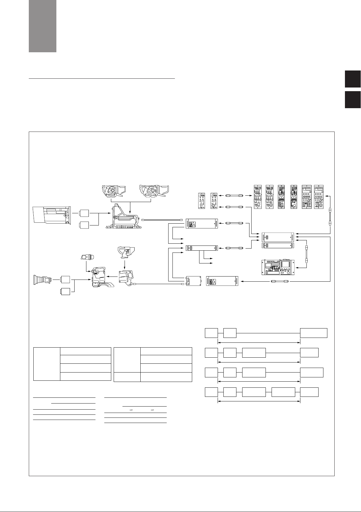
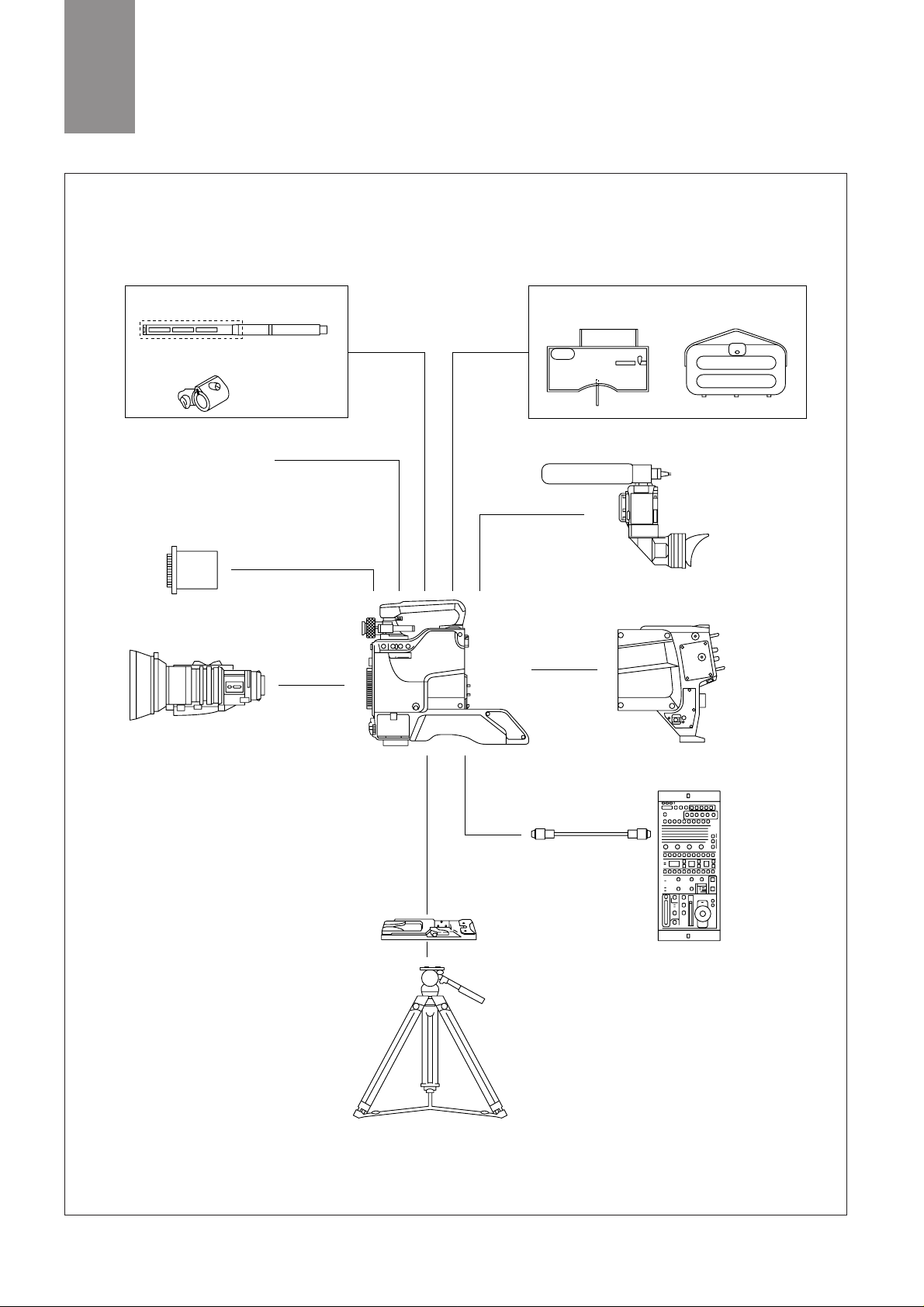
2-1. System Configuration
The BVP-900 Series is based on the renowned BVP-700 Series and
DSP technology pioneered by Sony in the earlier BVP-500 Series
camera system. This new system features two camera heads, the
BVP-900/900P full-size studio model and a full companion portable
camera, the BVP-950/950P. This por table model is designed for full
integration into a BVP-900/900P studio camera system, as well as
being used as a standalone acquisition camera in combination with
Betacam VTRs. Figure 2-2 shows how this interface is pr ovided by
the CA-553 50-pin Camera Adaptor. A variety of key peripherals, such
as the CNU-700 and CNU-500 Camera Command Network Units help
users to easily expand/upgrade their system. These peripherals
provide a perfect interface with the growing ranges of Sony digital
component equipment, such as Betacam SX and Digital BETACAM
products.
2
A TOTAL SYSTEM
STUDIO ZOOM LENS
CCD UNIT
OHB-750A/750AP
OHB-730/730P
OHB-750WSA/750WSAP
OHB-730WS/730WSP
COLOR VIDEO CAMERA
BVP-900/900P
BVF-77/77CE BVF-7700/7700P
TRIAX CABLE (*1)
CAMERA CONTROL UNIT
CCU-700/700P/700A/700AP
CAMERA CONTROL UNIT
CCU-550/550P(*3) CCU-700/700P/700A/700AP
*2: CCA-5 CABLE LENGTH
CCU-700
CCU-700
CNU-700
200 m
16 0 m
90 m
CNU-700 RCP-700/701
RCP-700/701
RCP-720/721/730
/731/740/741
CCU-700 CNU-700
RCP-720/721/730
/731/740/741
45 m
CCU-700
When the CA-570/570P is connected with the CCU-550/550P, use of intercom transmission channel is
limited to only one channel.
In this case, use the INCOM 1 connector of the CA-570/570P.
When the CCU is connected with the VCS-700, the PIX 2 and WF 2 connectors of the CCU are normally
used. When the CCU-550/550P is connected, use of PIX and WF transmission channels are limited to only
one channel respectively.
In this case, use the PIX and WF connectors for the CCU-550/550P.
*3:
*4:
CNU-700
RCP-720/721/730
/731/740/741
RCP-720/721/730
/731/740/741
RCP-720/721/730
/731/740/741
RCP-700/701/720
/721/730/731/740/741
VIDEO SELECTOR
VCS-700
REMOTE CONTROL
PANEL
RCP-720 RCP-721
REMOTE CONTROL PANEL
CCA-5 CABLE
(*2)
CAMERA COMMAND
NETWORK UNIT
CNU-700/500
MASTER SETUP UNIT
MSU-700
CCA-5 CABLE
(max. 200m)
RCP-730 RCP-731 RCP-740 RCP-741
RCP-700 RCP-701
CCA-5 CABLE
(*2)
PIX 2
PIX 2(*4)
WF 2(*4)
WF 2
CCA-5 CABLE
(*2)
CCA-5 CABLE
(*2)
CCA-5 CABLE
(max. 200m)
CCA-5 CABLE
(*2)
PIX
WF
2-inch VF(BVF-20W/20WCE)
1.35-inch COLOR VF(BVF-C10W)
1.5-inch VF(BVF-10/10CE)
ELECTRONIC
VIEWFINDER
BVF-55/55CE
CAMERA ADAPTOR
CA-570/570P
CA-550/1 550P/1
CCD UNIT
OHB-750A/750AP
OHB-730/730P
OHB-750WSA/750WSAP
OHB-730WS/730WSP
For BVP-900/900P
*1: TRIAX CABLE LENGTH
Diamater
8.5 mm
14.5 mm
1000 m
2000 m
700 m
1400 m
Maximum length
CCU-700 CCU-550
Diamater
8.5 mm
14.5 mm
500 m
1000 m
400 m
800 m
Cable-length limitation for
prompter signal transmission
CCU CAM CAM CCU
STANDALONE UNIT
BKP-7910/7910P
SCRIPT HOLDER
BKP-7911/7912
TRIAX UNIT
BKP-7010
RTS KIT
BKP-7913
For BVP-950/950P
For CA-550/550P
ELECTRET CONDENSER MICROPHONE
ECM-MS5
MICROPHONE
C-74
CRADLE SUSPENSION
CRS-3P
TELEPROMPTER UNIT
BKP-5971
COLOR VIDEO CAMERA
BVP-950/950P
TRIAX CABLE (*1)
ENG/EFP LENS
OTHER OPTIONAL ACCESSORIES
4 : 3
16 : 9
4 : 3
16 : 9
ELECTRONIC VIEWFINDER
Figure 2-1 System Configuration
2
1
7
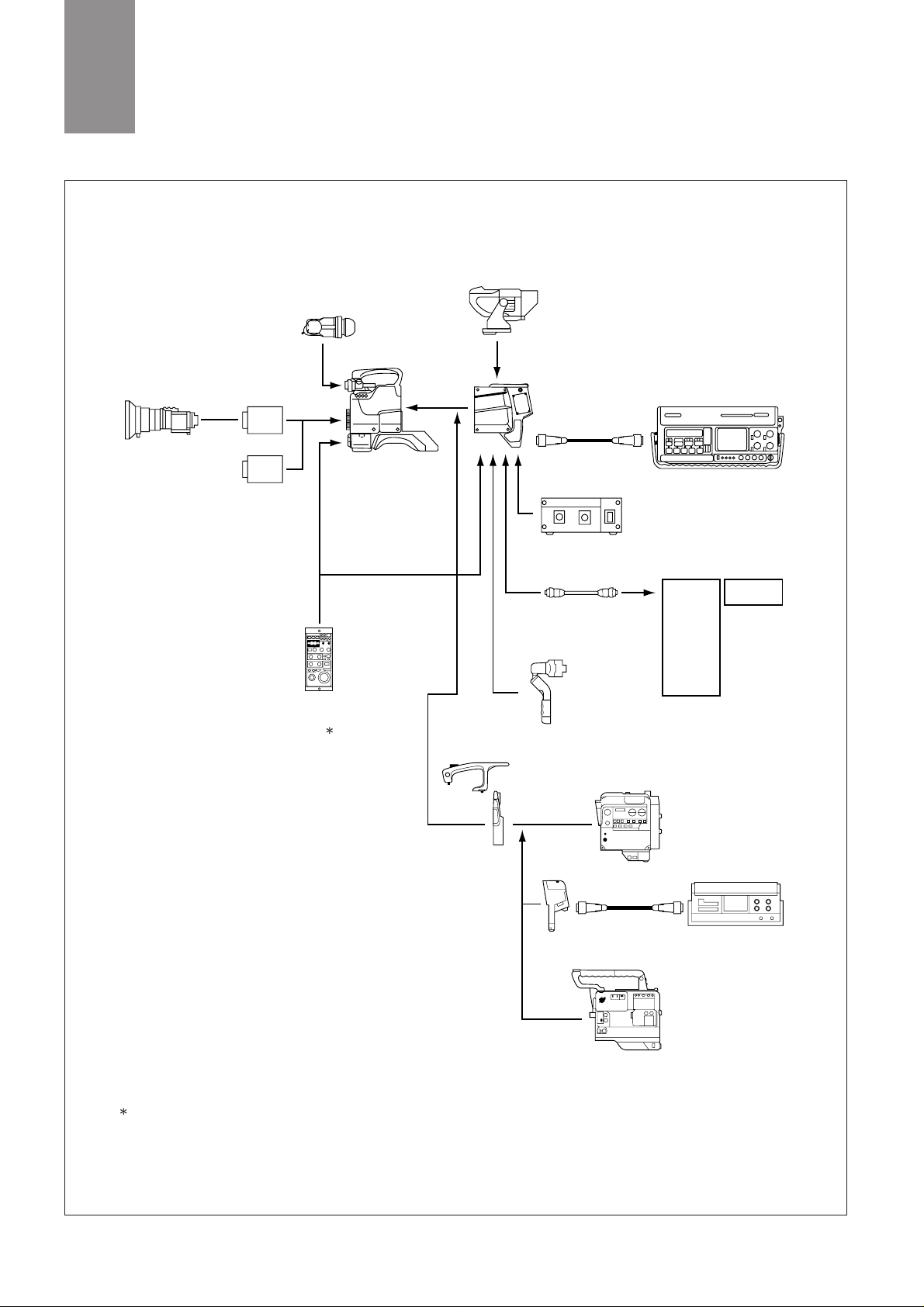
ENG/EFP LENS
REMOTE CABLE
(max. 100 m)
REMOTE
CONTROL
UNIT( )
RM-B150
CCZ CABLE
CCZ CABLE
When the CA-550/550P is connected to the RM-B150, video
signals cannot be output from the MONITOR connector of the
RM-B150.
:
VTR
RECORDER UNIT
DNV-5
CAMERA ADAPTOR
CA-3A
BETACAM
ADAPTOR
CA-553
VIDEO CASSETTE
RECORDER
BVV-5/5PS
REMOTE
CONTROL
PANEL
RCP-700
RCP-701
RCP-720
RCP-721
RCP-730
RCP-731
RCP-740
RCP-741
AC ADAPTOR
AC-550/550CE
CCA-5 CABLE
(max. 50m)
DIGITAL VIDEO CASSETTE
RECORDER
DVW-250/250P
CAMERA ADAPTOR
CA-570/570P
CA-550/1 550P/1
CA-530
ELECTRONIC
VIEWFINDER
BVF-55/55CE
COLOR VIDEO CAMERA
BVP-950/950P
OHB-750WSA/750WSAP
OHB-730WS/730WSP
2-inch VF(BVF-20W/20WCE)
1.35-inch COLOR VF(BVF-C10W)
1.5-inch VF(BVF-10/10CE)
4 : 3
16 : 9
CCD UNIT
OHB-750A/750AP
OHB-730/730P
MASTER
SETUP
UNIT
MSU-700
RETURN VIDEO
SELECTOR
CAC-6
Figure 2-2 System Configuration—Portable Cameras
2
A TOTAL SYSTEM
8
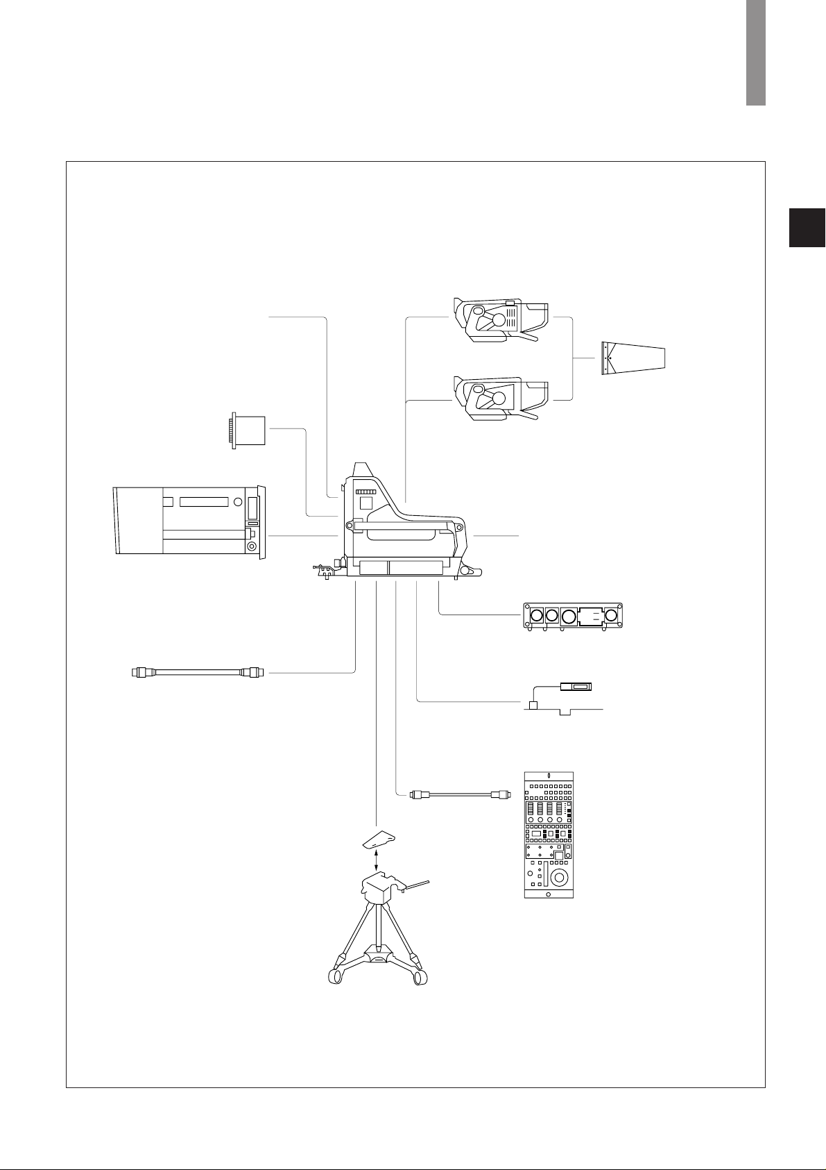
Front cover (supplied)
BVF-7700/7700P
(with standard hood)
7-inch viewfinder
VFH-770 7-inch Viewfinder
Sports Hood
BKP-7010 Long Triax Kit
BKP-7910/7910P Stand-Alone Kit
(for using the BVP-900/900P as a
stand-alone unit)
BKP-7911/7912 Script Holder
(a script light included)
RCP-700-Series
Remote Control Panel
or
RM-B150
Remote Control Unit
CCA-5 cable
Tripod
V-wedge shoe
(supplied with the tripod)
Triax cable
BVF-77/77CE
(with standard hood)
Zoom lens
OHB-750A/750WSA/730/730WS/
750AP/750WSAP/730P/730WSP
CCD Unit
BVP-900/900P
Color Video Camera
1
Figure 2-3 Optional Accessories for BVP-900/900P
2
A TOTAL SYSTEM
9
Caution
It is recommended to use the BVP-950/
950P in combination with the CA-570/
570P Camera Adapter.
If the BVP-950/950P is used with the
CA-550/550P, powering up may not be
executed correctly, depending on the
CA-550/550P version.
If you wish to use the CA-550/550P
instead, please contact your Sony
service representative.
VCT-14
Tripod Adaptor
Tripod
CCA-5 cable
(or the cable
supplied with
the RM-B150)
RCP-700-Series
Remote Control Panel
(or RM-B150
Remote Control Unit)
CA-530
CA-550/1 550P/1
CA-570/570P
Camera Adaptor
BVF-C10W
1.35-inch Viewfinder,
BVF-10/10CE
1.5-inch Viewfinder,
or BVF-20W/20WCE
2-inch Viewfinder
Water-resist cover
Microphone
CAC-12 Microphone Holder
Front cover (supplied)
Zoom lens
OHB-750A/750WSA/730/730WS/
750AP/750WSAP/730P/730WSP
CCD Unit
Carrying case
BVP-950/950P
Color Video Camera
Figure 2-4 Optional Accessories for BVP-950/950P
2
A TOTAL SYSTEM

10
2-2. Camera Head
BVP-900/900P — The BVP-900/900P is an outstanding color video
camera which incorporates Sony ADSP (Advanced Digital Signal
Processing) and 12-bit A/D conversion. Using industr y-first CCD
imager technology, the BVP-900/900P is easy to upgrade from the
4:3 standard to switchable 16:9/4:3 operation, allowing users to
capitalize on the growth in widescreen programming. Using the
proven Power HAD 1000 CCD with its excellent highlight handling,
the BVP-900/900P provides a 900 TV line resolution and achieves the
remarkably low smear level of -145dB (FIT). Just some of the state-ofthe-art features ar e:
* Triple skin tone detail
* Adaptive detail control
* Fine detail
* Electronic soft focus
* Adaptive highlight control
* Knee saturation
* 3-D white shading
* Multi matrix control
* Skin tone auto iris
These improvements contribute to an unsurpassed image quality,
making the BVP-900/900P a true ‘top-of-the-line’ studio/OB camera.
BVP-950/950P — The BVP-950/950P is the portable version of the
BVP-900/900P and has identical video processing circuitr y. Both
models have the same signal perfor mance and can be controlled
either at the camera head or by remote control through studio
system peripherals such as the CCU-700A/700AP Camera Control
Unit, MSU-700 Master Set-up Unit and CNU-700/CNU-500 Camera
Command Network Units. Because of this design concept, users of
the BVP-950/950P have the same features, the same operational
perfor mance and the same operational ‘feel’ as the BVP-900/900P an optimized solution to meet the needs of high-end users for a
companion studio portable camera.
The flexible interfacing of the BVP-900 and BVP-950 (and their
respective 625/50 PAL versions the BVP-900P and BVP-950P) means
that they are not only high-end broadcasting cameras with the latest
technology, but they can also be easily integrated into conventional
studio/OB vehicle systems that use earlier BVP-500 Series cameras.
Main Features of Camera Heads
(a) Excellent Picture Quality
* Sensitivity F10.0 at 2000 lx with OHB-750WSA/P, OHB-
730WS/P and OHB-730/P
F8.0 at 2000 lx with OHB-750A/P (3200 K, 89.9%
reflectance)
* S/N (Typical) 65 dB (NTSC), 63 dB (PAL)
* Resolution 900 TVL (4:3 OHB CCD models)
* Modulation 80% (at 5 MHz), DTL OFF
* Smear level -145 dB (With Power HAD FIT imager installed)
* Total absence of lag and highlight artifacts
(b) Wide band triax transmission
* 10 MHz for luminance channel
* Up to 2000 m cable length (with ø14.5 mm cable, with CCU-
700A/700AP)
* Up to 1000 m cable length (with ø8.5 mm cable, with CCU-
700A/700AP)
(c) Enhanced Camera Operator functions
* Picture in picture (BVP-900/900P only)
* Cursor memor y (BVP-900/900P only)
* Up to four (BVP-900/900P) or four (BVP-950/950P with CA-
570/570P) selectable return video feeds
(d) Advanced intercom system
* Individual ENG/PROD lines
* Microphone system
* PGM audio system
(e) Utility outputs (BVP-900/900P only)
* Up to 200VA
* 12 V DC output (for script light or wireless microphone receiver)
* Prompter output
(f) Full companion camera
* The BVP-950/950P portable camera has the same picture quality
and remote operational controls as the studio/OB camera BVP900/900P
(g) Compact size and easy maintenance
* Highly sophisticated mechanical design
* BVP-900/900P 20.0 Kg (44 lb 1 oz) (without viewfinder)
* BVP-950/950P 3.7 Kg (7 lb 5 oz) (with viewfinder and OHB)
* All boards plug-in for easy maintenance
(h) Convenient return video select
Up to four return video signal can be selected for operational
convenience. Return video switches and intercom switch are fitted on
the carrying handle of the BVP-950/950P to suit various shooting
styles.
(i) Comfortable BVP-950/950P operation
Thanks to a new soft material, the shoulder pad of the BVP-950/950P
comfortably molds to the operator’s shoulder. It incorporates a
pivoting chest pad and does not require for war d/backwar d
adjustment.
2-3. Camera Control Unit
The CCU-700A/700AP is a camera control unit for use with BVP-900
Series cameras. By incorporating of wideband Triax transmission
system and a digital control system, as well as three optional SDI
outputs, the CCU-700A/700AP offers maximum camera performance
combined with flexible operation. It has been designed to achieve the
highest reliability, afford easy maintenance and allow flexible system
configuration.
The CCU-550/550P Camera Control Unit is also available for use
with BVP-950/950P portable cameras. A compact body, two SDI
outputs (with a BKP-5972 option fitted) and optional 12 V DC
operation (BKP-5974) make this unit ideal for field use.
Main Features of the CCU-700A/700AP
(Camera Control Unit)
(a) Wideband triax transmission
* 10 MHz luminance channel for high perfor mance transmission; 6
MHz for each color difference signals
* Up to 2000 m cable length (with ø14.5 mm cable)
2
A TOTAL SYSTEM

11
2
A TOTAL SYSTEM
* Up to 1000 m cable length (with ø8.5 mm cable)
* Return video (up to 2000 m with ø14.5 mm cable and 1000 m
with ø8.5 mm cable)
* Prompter video (up to 1000 m with ø14.5 mm cable and 500 m
with ø8.5 mm cable)
(b) Easy-to-operate command system
* Immediate response
* Wide range of remote controls
(c) Mono color function
* Monochrome video is available to VBS and Y, R-Y and B-Y
outputs
* Hue (360 degrees) and saturation controllable from an MSU-700
Master Set-up Unit
(d) Character display
* Self diagnostics and other information may be displayed on a
monitor or superimposed on the picture monitoring output
* Characters, such as the camera number, can be superimposed on
the internal color bar signal
(e) Powerful self-diagnostics system
* ISR system interface provided
* Triax cable condition and the status of each board can be
monitored
(f) Component SDI output (option)
* Three component SDI outputs are optionally available for
interfacing to the ever increasing range of component digital
equipment and facilities
(g) Built-in contrast and saturation functions
* Contrast, saturation and chroma on/off contr ols provided
(h) Flexible intercom system
* Individual channels for producer and engineer
* 4W, 2W or RTS selectable by internal switch
(i) Remotely controllable MIC input gain (camera head)
* The gain of the two camera head microphone inputs controllable
from the CCU in 10 dB steps (-60 dB ~ -20 dB)
(j) Flicker-less sequential mode (RGB) standard for WFM output
* RGB sequential monitoring without flicker
(k) Compact size and easy maintenance
* 19-inch wide and 3U high, including camera power supply unit
* Plug-in boards and plug-in power supply unit for easy
maintenance
2-4. Control System
(Please refer to section 6. Control System for fur ther infor mation)
In addition to the MSU-700 Master Set-up Unit and eight different
types of RCP-700 Series Remote Control Panels, the CNU-700 and
CNU-500 Camera Command Network Units form the command
ner ve center for a new concept in camera control system. A wide
selection of control peripherals allow each user to configure the most
suitable system to meet a specific operational need. The following are
the key peripherals.
(a) Master Set-up Unit (MSU-700)
The MSU-700 Master Set-up Unit can control up to 6 cameras (up to
12 cameras by using an expansion board) in combination with the
CNU-700 Camera Command Network Unit. The adoption of an EL
Touch Panel in the MSU-700 helps to simplify the operation of its
sophisticated control system. And data such as scene files can be
stored in a world-standard PC memory card.
(b) Camera Command Network Units (CNU-700 and CNU-500)
The Camera Command Network Units are designed to be the ner ve
center of the Sony camera control system for the BVP-900 Series,
BVP-700 Series, BVP-500 Series and HDC-700 Series of cameras.
They work as ‘Command Selector’, ‘Command Distributor’ and
‘Command Arbitrator’. These two types of camera command network
units give a cost/perfor mance choice. The CNU-500 is suitable for
applications with up to six cameras, while the standard six cameras
capability of the CNU-700 can be expanded to 12 cameras with use of
the BKP-7930 optional expansion board. With the BKP-7932 optional
command conversion board installed instead of the BKP-7930, the
CNU-700 can operate with six previous-generation CCU-370/355/350
units as well as six CCU-700A/550 units.
The carefully designed software and the high-speed CPU of both the
CNU-700 and CNU-500 give them a fast response time whatever the
system configuration.
(c) Video Selector (VCS-700)
The VCS-700 Video Selector is used to switch composite video
monitoring signals from a BVP-900 Series multi-camera system to a
picture monitor and waveform monitor. The VCS-700 accepts the
video monitoring signal from up to six CCU-700A or CCU-550
Camera Control Units and switches these signals to two picture
monitor outputs and two waveform monitor outputs. The selection of
monitoring signals can be controlled by the camera selection buttons
on the MSU-700 Master Set-up Unit, or by external control
equipment through the D-sub 37-pin I/O port on the VCS-700.
For SDI monitoring, the optional BKP-7933 S-Bus Interface Board
provides connection to a Sony digital routing system.
(d) Remote Control Panels (RCP-700 Series)
There are four ranges of Remote Control Panel for the BVP-900
Series. Each range has two types - joystick control and dial control.
The RCP-740/741 is the top of the range for sophisticated operational
use, and can be used as a substitute for the MSU-700 Master Set-up
Unit in some special applications. The RCP-730/731 is the mid-range
model with general control function, especially useful for limited
space with its slim design. The RCP-720/721 is also a mid-range unit,
with sufficient control functions for general use. Finally, the RCP700/701 features the basic control items required for daily operation
of acquisition camera systems. The RCP-730/731, RCP-720/721 and
RCP-700/701 can all be used as a sub-control panel to support an
MSU-700 or RCP-740/741.
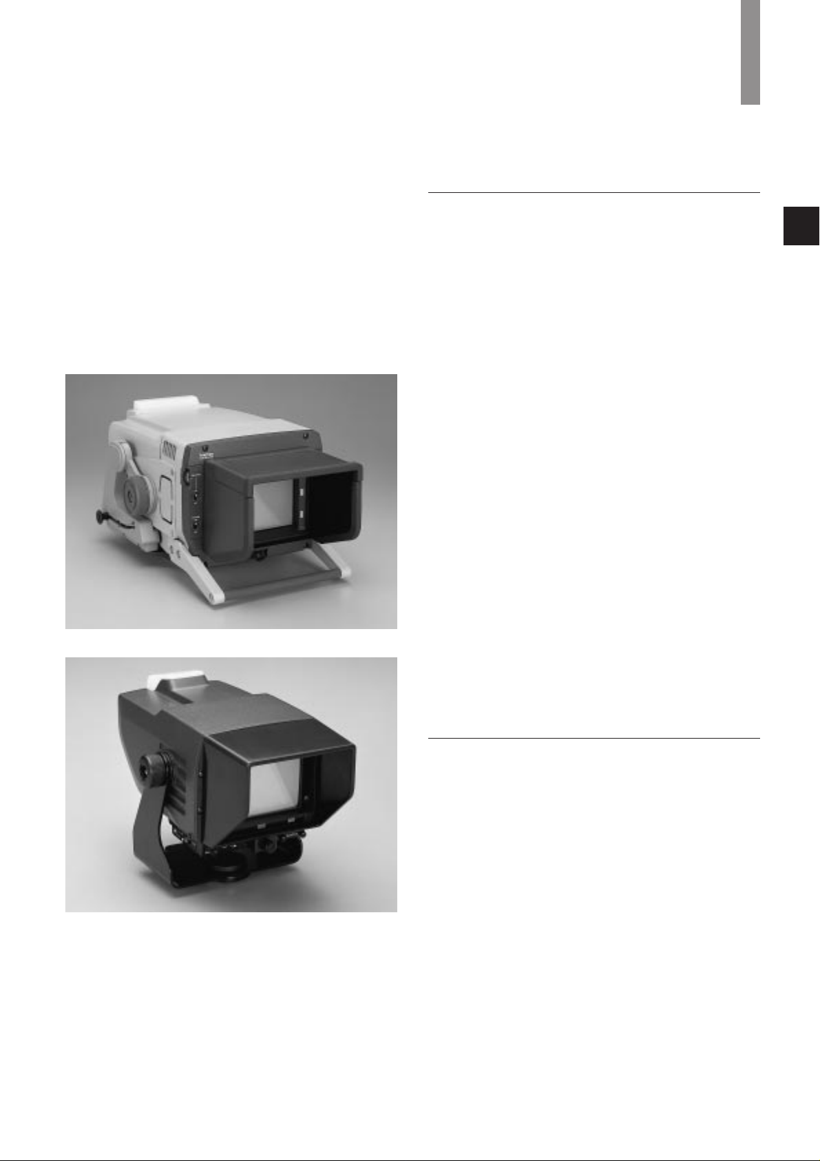
2-5. Viewfinders
As well as the BVF-77/77CE, a high perfor mance 7-inch
monochrome viewfinder with extremely high horizontal resolution,
the BVF-7700/7700P 7-inch high grade color viewfinder is also
available for the BVP-900/900P. This high grade color viewfinder is
especially convenient for cases where color needs to be identified by
the camera operator. For the BVP-950/950P, a 5-inch monochrome
viewfinder, the BVF-55/55CE, is available. All of these models are
ver y compact in size, light in weight and economical in power
consumption. The low mounting positions of the BVF-77 and BVF7700 Series provide convenient viewfinder displays aligned as close
as possible to the lens axis.
12
2
A TOTAL SYSTEM
- Picture-in-picture Function in Viewfinder (BVP-900/900P
only)
The viewfinder return video signal can be inserted into any one
of the four corners of the viewfinder display. Furthermore, the
camera and return video pictures can be interchanged.
- Indication of Zoom Position
As well as showing the ND/CC filter positions in the viewfinder,
lens zoom and iris settings can also be displayed, along with
alpha/numeric status displays.
- Viewfinder Box Cursor Memory (BVP-900/900P only)
Three combinations of box H position, V position, height and
width can be memorized and assigned to the three cursor
buttons.
2-6. BVP-900/900P Optional System Accessories
For Camera
BKP-7910/7910P Standalone unit for the BVP-900/900P
BKP-7911 Script Holder, one-page type with lamp, for the
BVP-900/900P
BKP-7912 Script Holder, two-page type with lamp, for the
BVP-900/900P
BKP-7913 RTS interface kit for the BVP-900/900P
For CCU/CNU/MSU
BKP-7311 SDI Output Board for CCU-700A/700AP
BKP-7312 SDI Return V/F I/P Board for CCU-
700A/700AP
BKP-7900 Extender Board for CCU-700A/700AP and
CNU-700/500
BKP-7930 Expansion Board for system expansion up to
12 cameras for the CNU-700
BKP-7931/7931P Sub-encoder Board for the CCU-700A
BKP-7932 BVP-370 Series Interface Board for the CNU-
700
BKP-7933 S-Bus Interface Boar d for CNU-700
BKP-5972 SDI Output Board for CCU-550/550P
BKP-5973 Control Panel for CCU-550/550P
BKP-5974 DC Power Unit for CCU-550/550P
CCA-5 Cables 8p-8p cables for the CNU-700/500, CCU-700A/550,
MSU-700, VCS-700 and RCP-700 Series
CCA-5-3 3 m
CCA-5-10 10 m
CCA-5-30 30 m
CCZ Cables 26pin-26pin VTR cable
CCZ-2 2 m (6.4 ft)
CCZ-10 10 m (33 ft)
2-7. A New Series of Viewfinders for the BVP-950/950P
Three types of viewfinders can be used with the BVP-950/950P
portable camera to provide the choice r equired in meeting different
applications. These viewfinder models have the following features:
BVF-C10W — Electronic Color LCD Viewfinder
* 1.35-inch, 16:9 widescreen color LCD viewfinder
* Incorporates 1.35-inch, wide aspect TFT active matrix color LCD
panel with 510,000 dots
* Non-interlace, high vertical resolution and less flicker by using a
Sony Line Doubler (double-speed conversion)
* High resolution of 400 TV lines in both 16:9 and 4:3 modes with
excellent color gradation to show the finest detail
* 16:9/4:3 automatic switching. When used in 16:9 mode, 4:3 limits
and box cursor can be selected to help in shooting 16:9 material
that may be converted later into the 4:3 standar d
* Peaking is shown in yellow for easy focusing
* Return signal can be monitored in color
* World-wide model automatically responds to the video input
standard, NTSC or PAL
* High perfor mance, triple magnification lens for better visibility
* Removable eye-piece allows direct view of the LCD
* Tally lamp for camera operator is located on the viewfinder body
Photo 2-1 BVF-7700/7700P
Photo 2-2 BVF-55/55CE
so that it can be seen even when not looking at the viewfinder
screen. It can be masked with a sliding cover
* Supplied with an external microphone
BVF-20W(NTSC)/20WCE(PAL) — Electronic Black and White
CRT Viewfinder
* 2-inch 16:9 widescreen B/W CRT viewfinder
* High resolution — 600 TV lines at center in both 16:9 and 4:3
modes
* Diagonal size is 1.5-inch in 4:3 mode and 2.0-inch in 16:9 mode to
ensure easy focusing even in 16:9 mode
* Removable eye-piece allows direct view of the LCD
* Tally lamp for camera operator is located on the viewfinder body
so that it can be seen even when not looking at the viewfinder
screen. It can be masked with a sliding cover
* Removable eye-piece allows direct view of the LCD
* Supplied with an external microphone
BVF-10(NTSC)/10CE(PAL) — Electronic Black and White CRT
Viewfinder
* 1.5-inch 4:3 standard B/W CR T viewfinder
* High resolution — 600 TV lines at center
* Diagonal size is 1.5-inch to ensure easy focusing
* Tally lamp for camera operator is located on the viewfinder body
so that it can be seen even when not looking at the viewfinder
screen. It can be masked with a sliding cover
* Removable eye-piece allows direct view of the LCD
* Supplied with an external microphone
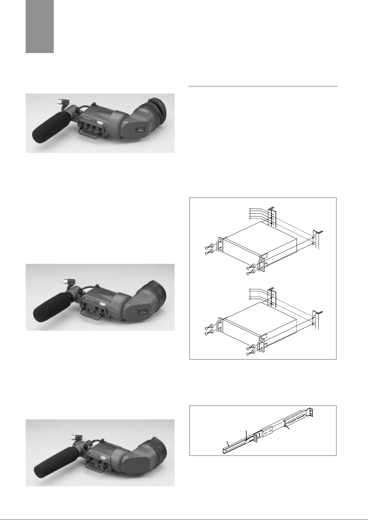
2-8. Rack Mounting of System Equipment
(a) 19-inch size equipment
The CCU-700A/700AP Camera Control Unit, CNU-700 and CNU-500
Camera Command Network Units, and VCS-700 Video Selector can
be mounted in a 19-inch standard EIA rack. These units either mount
directly into the rack or with optional slide rails such as the Sony
RMM-30 Rack Mount Rail. These slide rails allow the unit to be
easily pulled out from the rack and are recommended if you intended
to pull out the unit frequently.
Warning for Safety Purpose: It takes two or more people to mount a
unit into a rack. Mounting the unit into a rack by yourself can cause
back or other injuries.
Mounting the unit directly to the rack
Fix the unit to the rack using the rack mount bracket of the unit.
Daily maintenance is easy with the unit mounted with this method.
Mounting the unit using the RMM-30 Rack Mount Rail
When the RMM-30 Rack Mount Rail is used, the unit can be
mounted into a rack with a depth of 660 to 830 mm (26 to 32 3/4
inches). Proceed as follows:
1: Pull out inner member while pushing against the stopper
2: Secure the inner members to both sides of the unit with the
screws (+B4 x 8). Use the screws removed from or supplied
with the unit
Inner member
Stopper
Outer member
12.7
15.9
15.9
12.7
Universal-type rack
12.7
31.75
12.7
Wide-type rack
13
Photo 2-3 BVF-C10W
Photo 2-5 BVF-10/10CE
Photo 2-4 BVF-20W/20WCE
2
A TOTAL SYSTEM
14
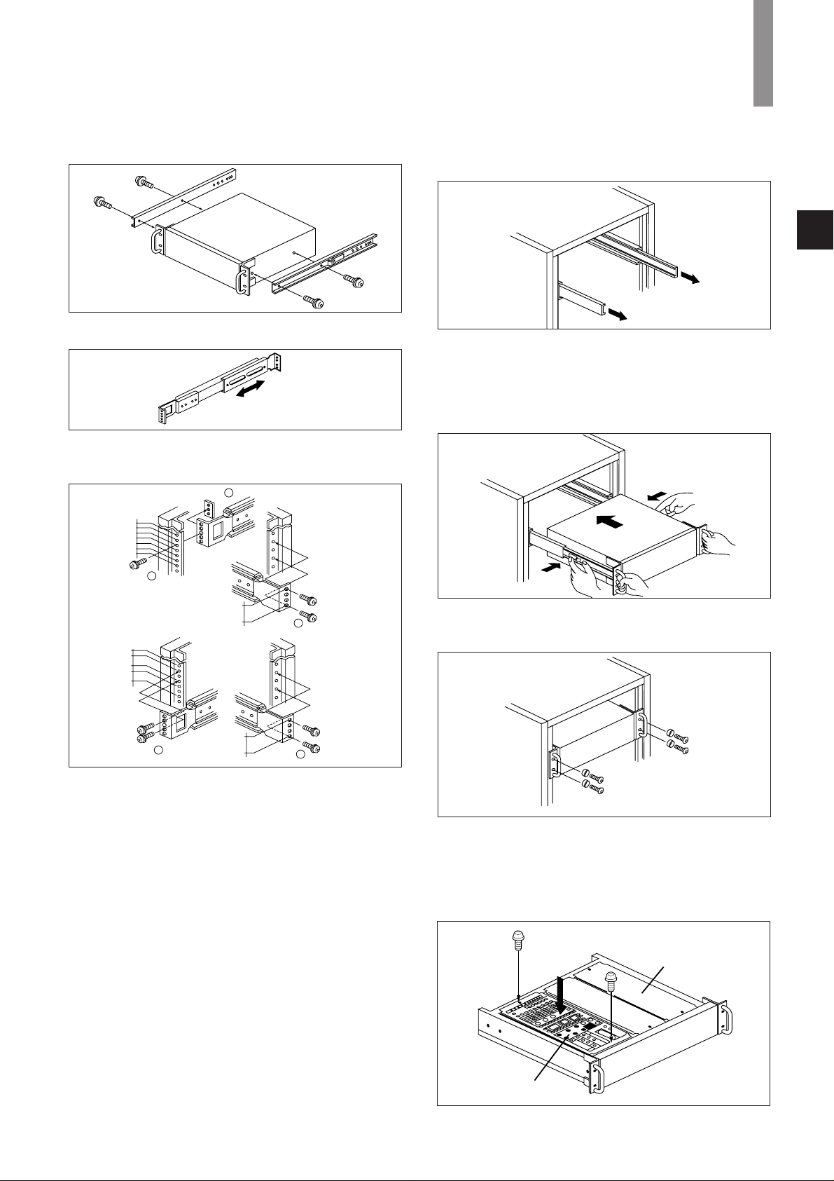
3: Loosen the screw of the bracket of the outer member
4: Attach the front and rear brackets of the outer member to the
rack. Screws (b), (c) and (d) are supplied with the RMM-30.
When a 1U unit is mounted
1) Attach the front bracket to the inside of the front of the rack at
the screw holes at 15.9 mm (22/32 inch) inter vals, using screw
(b) and plate nut (c).
2) Attach the rear bracket to the outside of the rear of the rack at
the screw holes at 31.75 mm (1 5/16 inches) inter vals, using
screws (d).
When a unit other than 1U height is mounted
1) Attach the front bracket to the outside of the front of the rack at
the screw holes at 31.75 mm inter vals, using screws (d).
2) Attach the rear bracket to the outside of the rear of the rack at
the screw holes at 31.75 mm inter vals, using screws (d).
5: Fasten the screws loosened in step 3.
12.7
12.7
31.75
31.75
12.7
31.75
15.9
15.9
15.9
15.9
12.7
Front
Front
Rear
Rear
Screw
b
Screw
d
Plate nut
c
31.75
Screw
d
Screw
d
6: Pull the rails out.
7: Insert the inner member to the outer member while pushing
against the stopper, then fully push the unit into the rack.
Warning for Safety Purpose: It takes two or more people to
mount a unit into a rack. Mounting the unit into a rack by
yourself can cause back or other injuries.
8: Push the unit into the rack, and secure the front panel to the
rack with screws (+RK M5 x 16 to 20) and washers (ø5).
(b) RCP-700 Series and MSU-700
The RCP-700 Series and the MSU-700 can be mounted into a 19-inch
rack using an optional drawer. Each type of equipment requires
different parts to mount it into the drawer. For details, please contact
your local Sony office.
2
RCP-700 Series
Drawer
Cover
2
A TOTAL SYSTEM
15
2
A TOTAL SYSTEM
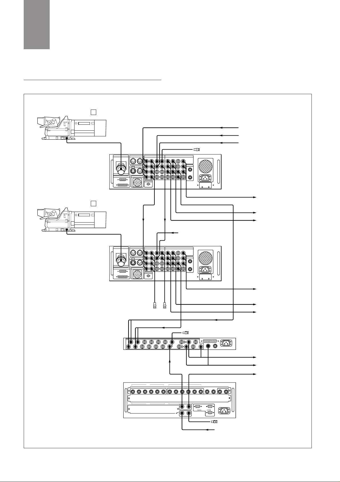
2-9. Basic Connection Examples
(a)Video-signal connections
When mixing the character signal with the output signal of the VCS700, set the SYNC ON/OFF switch (S7) on the internal board of the
CNU-700 to OFF.
7 8 9 10 11 12
CCU
123456
RCP
123456
7 8 9 10 11 12
CCU
MSU VCS AUX1 AUX2
AUX4
~AC IN
MSC VCS
AUX3
INPUT
COAX
MIX
CH-1 CH-2
RET1 R
G
B
WF1
PIX1
WF2
VBS1
VBS2
VBS3
Y
R-Y
PIX2 SYNC
RCP/CNU
WF MODE
AUX
CHARACTER
B-Y
REFERENCE
RET2
RET3
RET4
INTERCOM
REMOTE
CAMERA
RTS
MIC OUTPUT
REMOTE
INTERCOM/TALLY/PGM
OUTPUT
~
AC IN
INPUT
COAX
MIX
CH-1 CH-2
RET1 R
G
B
WF1
PIX1
WF2
VBS1
VBS2
VBS3
Y
R-Y
PIX2 SYNC
RCP/CNU
WF MODE
AUX
CHARACTER
B-Y
REFERENCE
RET2
RET3
RET4
INTERCOM
REMOTE
CAMERA
RTS
MIC OUTPUT
REMOTE
INTERCOM/TALLY/PGM
OUTPUT
~
AC IN
1
BVP-900-series camera
CCU-700A/700AP
Return video signal
Reference signal (BB)
Prompter signal
75-ohm terminator
Switcher, monitor
VTR
Reference signal (BB)
75-ohm terminators
CCU-700A/700AP
75-ohm terminator
Picture monitor
Switcher, monitor
VTR
Chroma keyer
Waveform monitor
Character monitor
75-ohm terminator
CNU-700
Reference signal (BB or BS)
VCS-700
Chroma keyer
RET1/RET2/RET3/RET4
REFERENCE
PROMPTER
RET1/RET2/RET3/RET4
REFERENCE
R/G/B
Y/R-Y/B-Y
WF2/PIX2
CAMERA
PROMPTER
REFERENCE
RET1/RET2/
RET3/RET4
VBS1/VBS2/VBS3
CAMERA
PROMPTER
RET1/RET2/RET3/RET4
WF1/PIX1
WF2/PIX2
CHARACTER
CHARACTER
PIX A/SYNC
CHARACTER CHARACTER
REFERENCE
WF A/WF MODE
VBS1/VBS2/VBS3
WF2/PIX2
Y/R-Y/B-Y
R/G/B
REFERENCE/
PROMPTER
2
BVP-900-series camera
Figure 2-5
16
2
A TOTAL SYSTEM
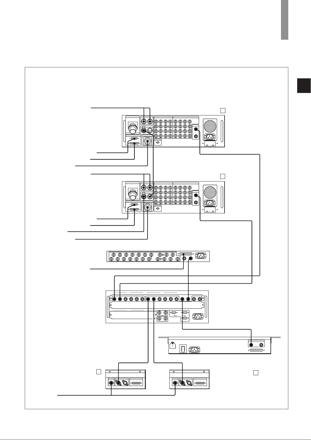
(b)Connection of control, intercom, tally and audio signals
7 8 9 10 11 12
CCU
123456
RCP
123456
7 8 9 10 11 12
CCU
MSU VCS AUX1 AUX2
AUX4
~AC IN
MSC VCS
AUX3
INPUT
COAX
MIX
CH-1 CH-2
RET1 R
G
B
WF1
PIX1
WF2
VBS1
VBS2
VBS3
Y
R-Y
PIX2 SYNC
RCP/CNU
WF MODE
AUX
CHARACTER
B-Y
REFERENCE
RET2
RET3
RET4
INTERCOM
REMOTE
CAMERA
RTS
MIC OUTPUT
REMOTE
INTERCOM/TALLY/PGM
OUTPUT
~
AC IN
INPUT
COAX
MIX
CH-1 CH-2
RET1 R
G
B
WF1
PIX1
WF2
VBS1
VBS2
VBS3
Y
R-Y
PIX2 SYNC
RCP/CNU
WF MODE
AUX
CHARACTER
B-Y
REFERENCE
RET2
RET3
RET4
INTERCOM
REMOTE
CAMERA
RTS
MIC OUTPUT
REMOTE
INTERCOM/TALLY/PGM
OUTPUT
~
AC IN
PREVIEW REMOTE
CCU/CNU
AUX
PREVIEW REMOTE
CCU/CNU
AUX
~AC IN
POWER
FUSE
I/O PORT
AUXCCU/CNU
REMOTE
1
CCU-700A/700AP
2
RCP-700 series unit
1
RCP-700 series unit
2
CCU-700A/700AP
Microphone signal output
Microphone control and tally
Microphone signal output
Intercom control and tally
Intercom and tally
Microphone control and tally
Intercom and tally
VCS-700
CNU-700
MSU-700
Selection of input signals
Switcher
Intercom control and tally
RTS intercom
RCP/CNU
RCP/CNU
RTS
MIC REMOTE
MIC REMOTE
MIC OUTPUT RTS
RTS
CCU 1
CCU/CNUCCU/CNU
PREVIEWPREVIEW
CCU 2
RCP 1 RCP 2 MSU
CCU/CNU
VCS
I/O PORT REMOTE
INTERCOM REMOTE
INTERCOM REMOTE
INTERCOM/TALLY/PGM
INTERCOM/TALLY/PGM
MIC OUTPUT
Figure 2-6
17
3
SONY ADVANCED ELECTRONIC IMAGING TECHNOLOGIES
3-1. Industry-first Plug-in Imager Assembly
The Plug-in Imager Assembly is in the form of a self-contained
imaging subsystem. It is, in essence, a miniature plug-in camera
containing the CCD block and all its support systems. This imager
assembly can be easily removed and installed so that operators with
no special skills can easily exchange imager assemblies in the field.
There are several types of Imager Assembly. The OHB-750A/750AP
is a 2/3-inch 4:3 FIT type CCD and the 750WSA/750WSAP is a 2/3inch 16:9/4:3 switchable widescreen FIT type CCD. For IT types, 4:3
standard screen sized OHB-730/730P and 16:9/4:3 switchable
widescreen OHB-730WS/730WSP are available. The latest Power
HAD technology achieves superior S/N ratio and extremely low
smear level. One ver y beneficial feature is that no readjustment is
required after exchanging these imager assemblies. This
breakthrough concept also of fers a highly cost-effective way of
upgrading CCDs over the camera life span.
OHB-750A/750AP
4:3 standard image format FIT CCD sensor, with remote control
of its CC/ND filter.
OHB-750WSA/750WSAP
16:9/4:3 switchable widescreen image format FIT CCD sensor,
with remote control of its CC/ND filter and aspect ratio
converter boar d.
OHB-730/730P
Fitted with a 4:3 standard image format IT CCD sensor, with
remote control of its CC/ND filter.
OHB-730WS/730WSP
16:9/4:3 switchable widescreen image format IT CCD sensor,
with remote control of its CC/ND filter and aspect ratio
converter boar d.
3-2. Sony CCD Advantages
Since the early 1970s, Sony has remained in the forefront of CCD
OHB-750WSA/750WSAP
16:9/4:3 switchable
620K FIT (PAL)
520K FIT (NTSC)
OHB-750A/750AP
4:3 620K FIT (PAL)
4:3 520K FIT (NTSC)
OHB-730WS/730WSP
16:9/4:3 switchable
620K IT (PAL)
520K IT (NTSC)
OHB-730/730P
4:3 620K IT (PAL)
4:3 520K IT (NTSC)
BVP950/950P
+
CA570/570P
BVP-900/900P
STUDIO/OB COMPANION PORTABLE
STANDARD
ECONOMICAL
Figure 3-1 Optimizing cost / performance choice with alternative OHBs
18
3
SONY ADVANCED ELECTRONIC IMAGING TECHNOLOGIES
imager technology with a sustained, broad-ranging research and
development program. The benefits of this technological
commitment can be seen in the wide range of Sony CCD cameras from mass produced types for consumer use to professional cameras
for field and studio operations. The top end of this range has now
been further expanded with the introduction of the Power HAD 1000
16:9/4:3 switchable widescreen CCD sensors for the BVP-900 Series.
Total picture performance is a complex function of many attributes in
imager y. Improvements in overall camera picture quality are a result
of continuing developments of the CCD imager, the CCD support
circuitr y and video processing. As the CCD imager itself r emains
central to the direction of recent camera development, enhancements
to the total perfor mance of CCDs for broadcasting cameras ar e of
critical importance. For this purpose, Sony developed the Power
HAD 1000 and has continuously been refining it ever since.
3-3. Power HAD 1000 CCD
The Power HAD 1000 CCD has 1038 horizontal picture elements, a
total of 520,000 for NTSC and 620,000 for PAL. Introduced with the
previous generation of cameras, the BVP-500 Series, Sony improved
the Hyper HAD 1000 CCD to complement 10-bit DSP. For the new
‘top of the line’ BVP-900 Series, Sony has developed a totally new and
outstanding design of CCD imager to complement its 12-bit ADSP for
the following reasons.
High picture quality
With its extremely high pixel count, the Power HAD 1000 provides a
horizontal resolution of over 900 lines, a high depth of modulation of
80% and minimum aliasing. Sony advanced semiconductor
technologies also give the Power HAD 1000 high sensitivity and ver y
low smear - despite its large number of picture elements. With the
inherent high level of picture quality provided by this imager, the
precise picture adjustment capability of digital cameras becomes
even more important.
Excellent matching of CCD and camera to digital environment
The Power HAD 1000 has not just been developed to provide
excellent picture quality. When developing a CCD for digital cameras,
the relationships between CCD drive clock frequency, digital signal
processing sampling rate and the digital VTR sampling rate have to
be considered. Simple relationships between these three parameters
result in easy signal conversion from CCD output to digital video
signal, in turn reducing the complexity of the digital LSIs and
reducing camera power consumption. The 18 MHz clock frequency
of the Power HAD 1000 was chosen to fulfill this requirement. It has
a direct relationship to the 18 MHz and 36 MHz sampling rates in the
camera and a simple, 4/3 relationship, to the 13.5 MHz sampling
frequency of the Digital BETACAM™ format.
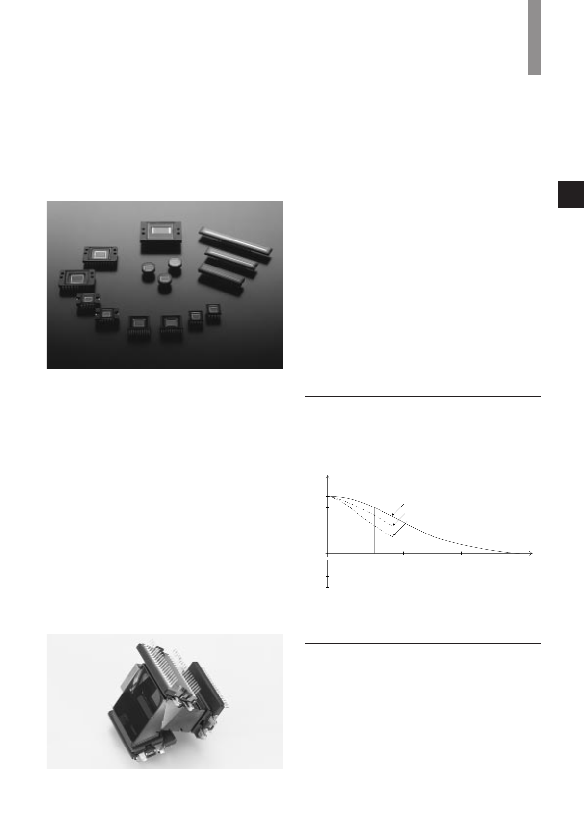
3-4. High Depth of Modulation
The high packing density achieves an excellent depth of modulation
perfor mance of 80 % at 5 MHz.
3-5. Minimum Aliasing with New Optical Low-Pass Filter
Incorporating the Power HAD 1000 in the BVP-900 Series involves an
extremely high sampling rate of 18 MHz. This high clocking rate, in
combination with precision CCD spatial offset and the exclusive
design of the new optical low-pass pre-filter, reduces aliasing to a
level never achieved in previous generations of CCD cameras.
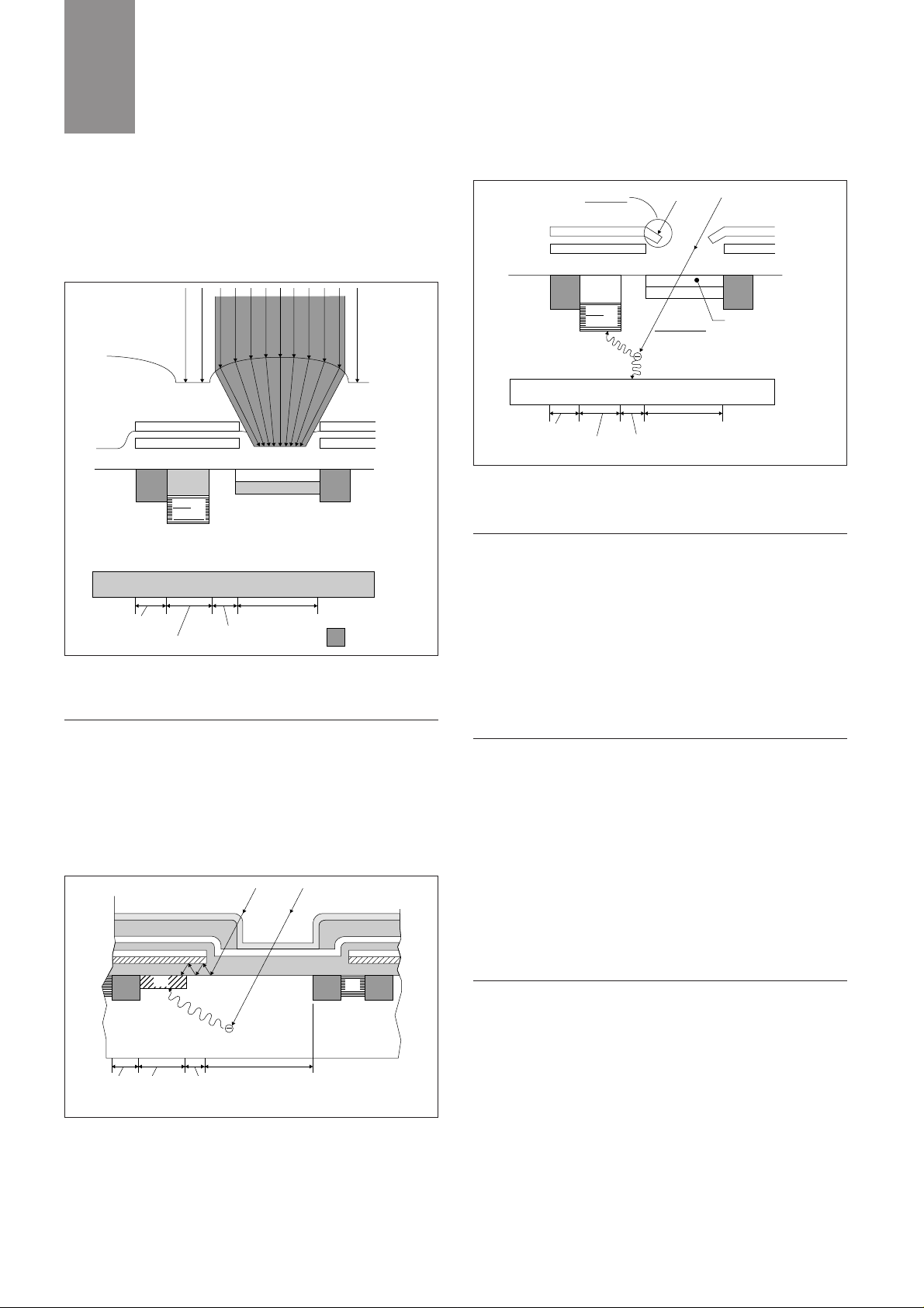
3-6. High Sensitivity
The power HAD 1000 CCD imager inherits the OCL (On-Chip-Lens)
technology used in all other Sony broadcast-range cameras. The OCL
layer of the CCD chip effectively concentrates the incident light on
Photo 3-1 Sony leading technology used in these CCDs is applied in the
Power HAD 1000 imager
Photo 3-2. Sony Power HAD 1000 CCDs
-0.6
-0.4
-0.2
0.2
0
0.4
0.6
0.8
1.0
1.2
RESPONSE
2 4 6 8 10 12 14 16 18 20
HORIZONTAL FREQUENCY (MHz)
Pbo (2/3")(QX3457)
Pbo (1-1/4")(XQ3430)
Power HAD (520,000 pixels)
0.8
Overrall Y Response
(with Optical LPF, without Lens)
cf2: Pbo (1-1/4")(XQ3430)
cf1: Pbo (2/3")(QX3457)
0
Figure 3-2. Depth of Modulation characteristic
19
the photo sensor area by precisely positioning a microlens over each
pixel. As a result, the camera sensitivity is doubled, achieving a
figure of F10.0 at 2000 lux with OHB-750WSA/P, OHB-730WS/P and
OHB-730/P. (F8.0 with OHB-750A/P.) The following Figure 3-5
shows how the OCL enhances sensitivity.
3-7. Invisible Smear Level
The OCL layer in the Power HAD imager effectively concentrates the
incoming light on the photo sensor so that leakage of light is greatly
reduced. The direct result of this is a very low smear level (even on
the IT sensors). This further improvement of the masking
techniques in the Power HAD 1000 (FIT) has reduced the smear to a
level of -145 dB (FIT), which is invisible. The following Figure 3-4
and 3-5 shows the new techniques.
3-8. Excellent Signal-to-Noise Ratio
The superior structure of the Power HAD imager greatly contributes
to a reduction in the dark current noise to 1/10 of that in the
previous generation of CCDs. This gives a corresponding r eduction
in the fixed pattern noise, maintaining low noise characteristics in all
imaging situations. In combination with an advanced CCD support
system, the Power HAD 1000 incorporated in the BVP-900 Series
achieves the excellent signal-to-noise ratio of 65 dB (typical) for
NTSC and 63 dB (typical) for PAL.
3-9. Super EVS (Enhanced Vertical Definition System)
The basic Enhanced Vertical Definition System (EVS) can sometimes
cause line flicker due to the increase in vertical definition. Super
EVS, which is available on BVP-900 Series cameras fitted with FIT
sensors, allows the vertical resolution to be enhanced over a range of
400 to 450 lines for NTSC and from 450 to 530 lines for PAL This is
achieved by changing the charge mixing ratio in the CCD read out.
This function is remotely controlled from the MSU-700 Master Set-up
Unit and permits the balance between ver tical resolution and motion
blur to be optimized for different scene contents, while keeping line
flicker to a minimum.
3-10. Clear Scan and ECS (Extended Clear Scan)
The well proven Clear Scan and ECS functions eliminate banding
effects when shooting monitor displays by allowing the shutter speed
to be adjusted so that it exactly matches the various scanning
frequencies that are in use. For FIT CCDs, the Clear Scan shutter
speed range is 60.1 to 7000 Hz for NTSC and 50.2 to 9000 Hz for
PAL, the ECS range is 30.4 to 58.3 Hz for NTSC and 25.4 to 48.5 Hz
for PAL. For IT CCDs it is 60.1 to 7000 Hz for NTSC and 50.2 to 9000
Hz for PAL. The ECS function is especially effective for shooting
computer displays that have vertical scanning rates below 60 Hz.
Al
Si
Al
Si
On-Chip-Lens
P+ P+
N+
N+
2nd
P-Well
Hole Accumulated Layer
1st P-Well
C.S
(Channel
stop)
V-register
Sensor
Sensed light
R.O.G
(Read out gate)
N-Substrate
Figure 3-3 On-chip-lens structure
P+P+P+
N+
N+
C.S
(Channel
stop)
V-register SensorR.O.G
(Read out
gate)
Figure 3-4 Smear Pattern of the previous generation of CCDs
Si
Ai
Si
Ai
P+ P+
N+
N+
2nd
P-Well
Masking
1st P-Well
Hole Accumulated Layer
C.S
(Channel
stop)
V-register
Sensor
N-Substrate
R.O.G
(Read out gate)
Figure 3-5 Power HAD 1000 CCD imager
3
SONY ADVANCED ELECTRONIC IMAGING TECHNOLOGIES
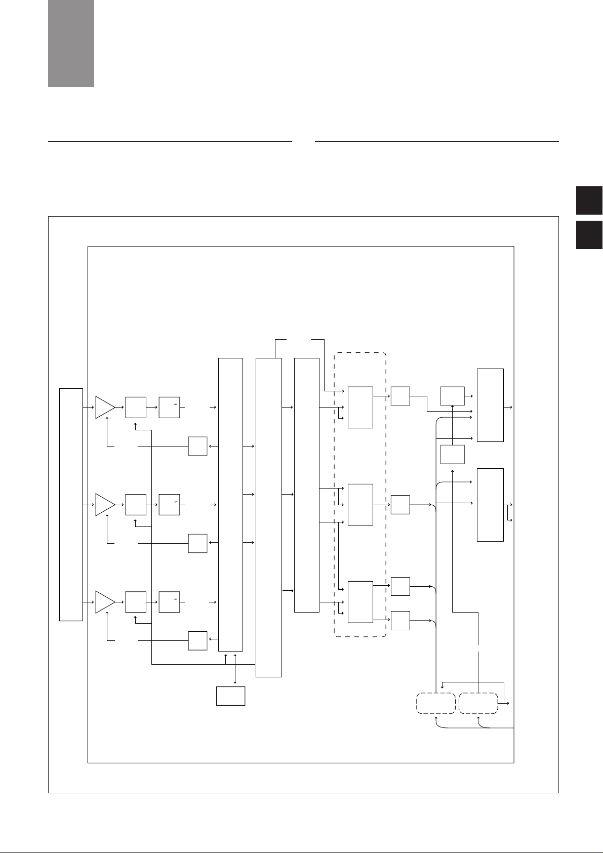
20
4
3
4
SONY ADVANCED DIGITAL SIGNAL PROCESSING (ADSP)
4-1. Basic block diagram
The following diagram shows how Sony has applied its innovative
skills in semiconductor technology to the design of BVP-900 Series
cameras.
4-2. Image Capture
A wide choice of Optical Head Blocks (OHBs) is available for BVP900/900P and BVP-950/950P cameras. Each camera is fitted with one
of four types of 2/3-inch IT or FIT Power HAD 1000 CCDs. The Red,
Green and Blue CCD sensors are fixed to the prism block using
CHU
OHB
PROMOTER
TRIAX
R white
shading
B white
shading
B white
shading
R 12-bit
G 12-bit
B 12-bit
R
RY
VF DTL
R
G
B
R video
G video
B video
G
G
B
B
RC-68
(option)
MD-83 DM-97
OHB-750A/WA
AP/APW
AMP
12-bit
A/D
+5v
+2.5v
AMP
12-bit
A/D
+5v
+2.5v
AMP
12-bit
A/D
+5v
+2.5v
D/A
D/A
D/A
D/A
D/A
D/A
D/A
SH IE PR
ARC
ARC
ARC
Pinp
Y/C sep
VF out
select
VF out
TEST out
RM out
TEST out
select
SRAM
RET
YR/-Y,B-Y
RET
PROMP
Figure 4-1 ADSP Block Diagram

21
Spatial Offset Technology to provide higher resolution. The image
captured on the photosensors of each CCD is read out at a clock
frequency of 18 MHz.
4-3. Analog Signal Processing Domain
Gain boost process is perfor med in the analog domain by a Video
Amplifier circuit. After that white balance and pre-knee are processed
with an AD board. The video signal from the CCD, which can have a
dynamic range of 600% of nominal white level, is compressed to
approximately 340% by this pre-knee process and conver ted to a 12bit digital signal at an 18 MHz sampling rate. This is the same
sampling frequency as that of the Power HAD 1000 imager.
4-4. Digital Signal Processing Domain
The camera signal processing is executed in the digital domain in
BVP-900 Series cameras. Within this digital processing, more than 12
bits are used in critical applications such as shading compensation,
image enhancing and gamma correction.
As shown in the diagram, three VLSIs are used for processing. In the
SH VLSI, the peak and average levels are measured, together with
other parameter of the video signal. These measurements are sent to
the analog circuits as feedback signals. The PR circuit contains the
main camera processing; gamma controls, knee slope controls and so
on. The RC circuit is used for aspect ratio conversion between 16:9
and 4:3. The ARC is a separate board supplied with widescreen,
switchable, OHB CCDs. The SH, IE, PR and ARC are using the latest
VLSI technologies.
4
SONY ADVANCED DIGITAL SIGNAL PROCESSING (ADSP)
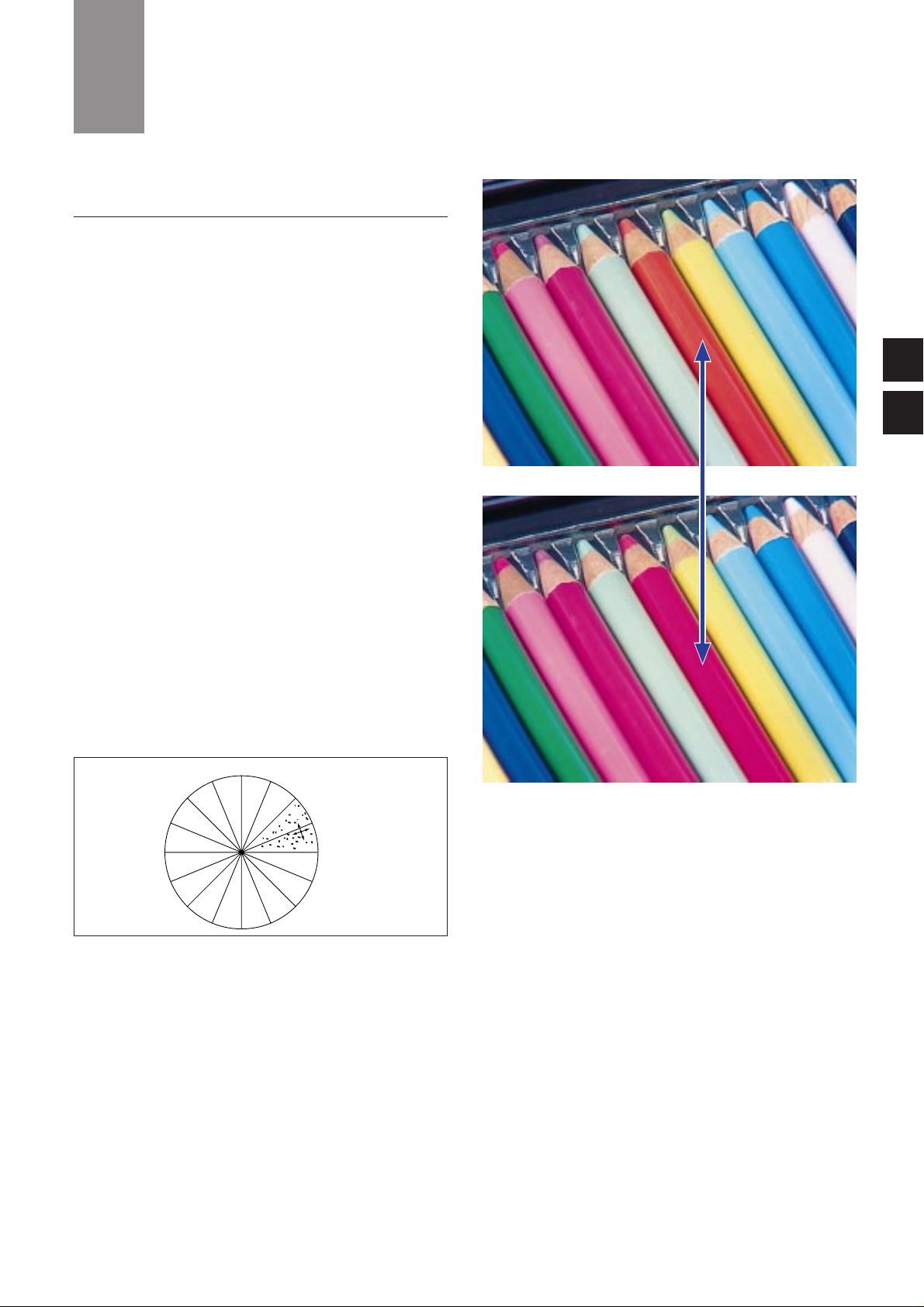
22
5-1. Full DSP Camera Processing
The BVP-900 Series uses 12-bit A/D conversion based on the latest
LSI technology. This advanced technology has allowed Sony to take a
major step for ward fr om the 10-bit conversion of its previous
generation of cameras – a move that was not possible with earlier
A/D converters and DSP LSIs.
(a) Multi Matrix
Multi Matrix is a function that electrically adjusts the basic RGB
color ‘taking characteristics’ of the camera to achieve optimum
colorlimetr y. It makes it easy to match the color of cameras under
multi-camera operations, or to reproduce the characteristics of
another type of camera. It can also be used to manipulate color for a
particular special effect. A conventional linear matrix function
provides only six adjustable parameters, with considerable
interaction between their effect on a specific color. Multi Matrix
divides the spectrum into 16 segments, each of 22.5 degrees, for
each of which there is an independent hue and saturation parameter.
Multi Matrix allows the selection of each of these segments, with
separate adjustment of hue and saturation parameters. Operation
flow is as follows:
1) Select Multi Matrix on the paint menu of the MSU-700 Master
Set-up Unit.
2) Tur n the Matrix and the Multi switches to ON.
3) The MSU-700 EL display now shows a representation of the
Multi Matrix as it would appear on a vectorscope. You can
select the desired color phase that you want to adjust.
4) After selection of the color phase, its hue and saturation can
be adjusted.
5
BENEFITS OF SONY ADSP
5
4
R–Y
B–Y
saturation
hue
Figure 5-1 Multi Matrix
Photo 5-1 Multi Matrix ON and OFF
ON
Normal

23
(b) Auto Knee
When the Auto Knee button on the MSU or RCP panel is pressed, it
optimizes the knee point and knee slope for best reproduction of the
high lights. The Adaptive Highlight control function can also be used
in conjunction with Auto Knee.
(c) Gamma
New 12-bit A/D conversion defines more precisely the required
gamma characteristic by using a gamma cur ve created from 48
segments. This is in comparison with the 32 segments in the
previous camera range.
(d) Black Gamma
Black Gamma allows control of the linear part of the gamma
characteristic, providing adjustment of the shadow areas of the
picture during shooting.
(e) Black Clip
Improvements in the Black Clip circuitr y have impr oved the
signal/noise ratio for more natural reproduction.
(f) Auto Black/White
The BVP-900 Series provides perfect accuracy in black and white
balance.
5
BENEFITS OF SONY ADSP
Photo 5-2 Multi Matrix (Vectorscope)
Input signal level
Output signal level
white clip
auto slope
point limit
auto knee circuit
Figure 5-2 Auto Knee curve image
Normal
ON
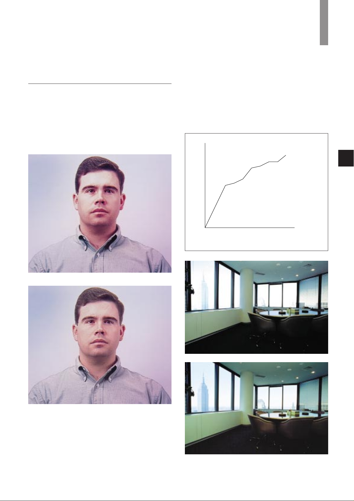
5-2. Precise Handling of Highlight Position
(a) Optimized bit assignment
The video level up to 260% is processed linearly. Highlights over 260%
are compressed by a pre-knee circuit before A/D conversion,
providing the most efficient utilization of the 12-bit A/D conversion
process.
(b) Knee Saturation
Knee Saturation eliminates both the ‘washed out’ effect and hue
changes in overexposed areas of a picture, providing more natural
color reproduction.
(c) Adaptive highlight control (Auto Knee mode)
Conventional cameras only have a single knee point/slope
characteristic. In contrast, the Sony ADSP system has multiple knee
point/slope characteristics. The camera intelligently monitors the
brightness of all areas of the picture and adapts the knee point/slope
for optimum reproduction. A typical example is shooting an interior
scene which includes a sunlit exterior seen through a window. This
new function applies only to video levels in excess of the knee point,
the middle and low luminance parts remaining unchanged.
24
white clip
auto slope
knee point 0
knee point 1
knee point 2
knee point 3
knee point n
Output signal level
Intput signal level
……
Figure 5-3 Knee curve image
5
BENEFITS OF SONY ADSP
Photo 5-3 Knee Saturation ON and OFF
Photo 5-4 Adaptive highlight control ON and OFF
Normal
Normal
ON
ON
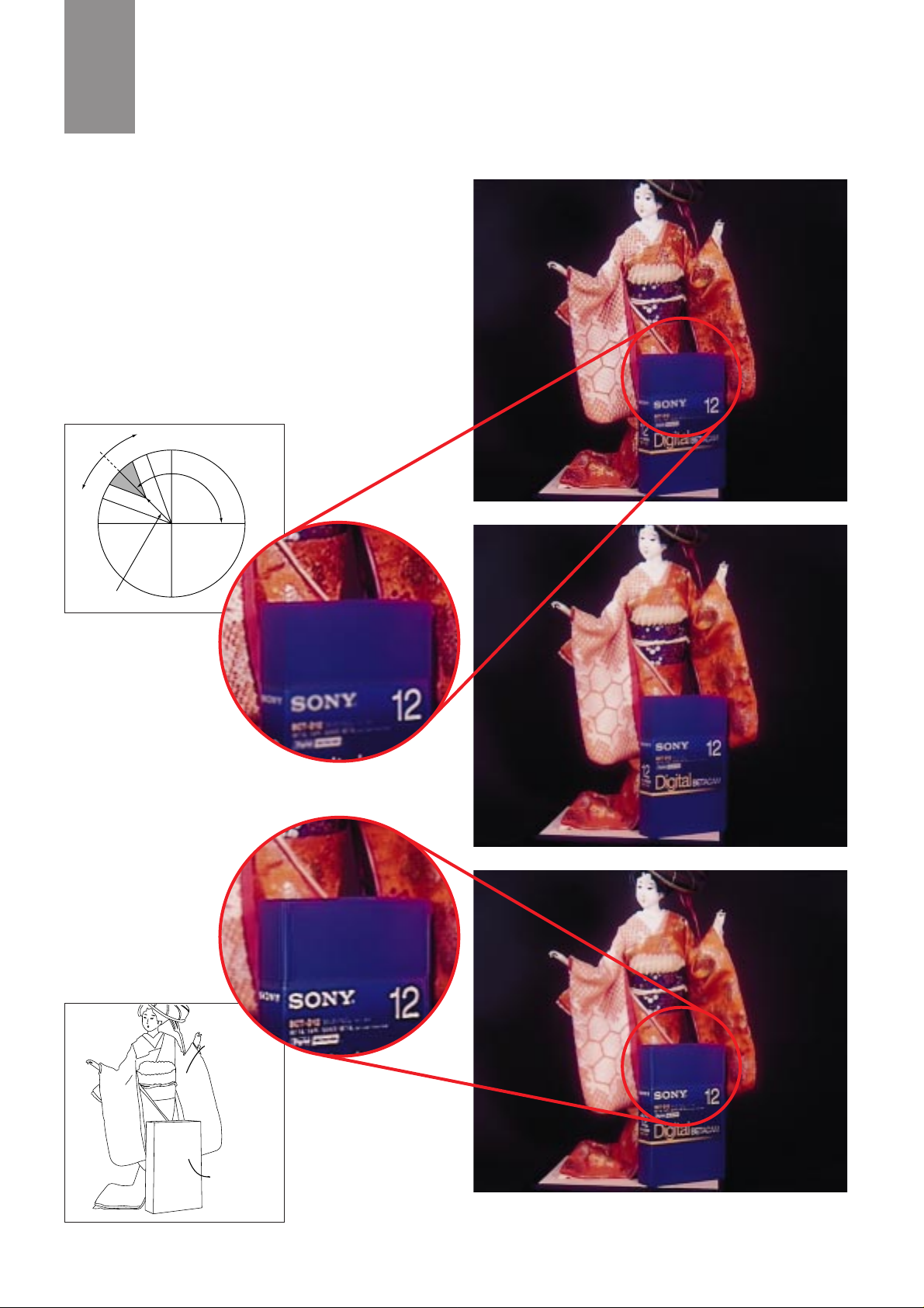
Moderation (Red)
Enhancement (Blue)
5
BENEFITS OF SONY ADSP
25
(d) Triple Skin Tone Detail Correction
Skin Tone Detail Correction controls the detail level of those objects
which have specific color tones. The BVP-900 Series allows detail to
be set independently for each of three separate color ranges. Colors
are not limited to skin tones, but can be set for any color. Detail may
be increased or decreased relative to the normal level.
Phase: Sets the color phase for which Skin Tone Detail
Correction is activated.
Width: Sets the color width for which Skin Tone Detail Correction
is activated.
Saturation: Sets the saturation for which Skin Tone Detail
Correction is activated.
R–Y
Width
B–Y
Phase
Saturation
Figure 5-4 Skin Tone
Detail Correction
Photo 5-5 Triple Skin Tone Detail Correction ON and OFF
Normal
CH1 ON
CH2 ON
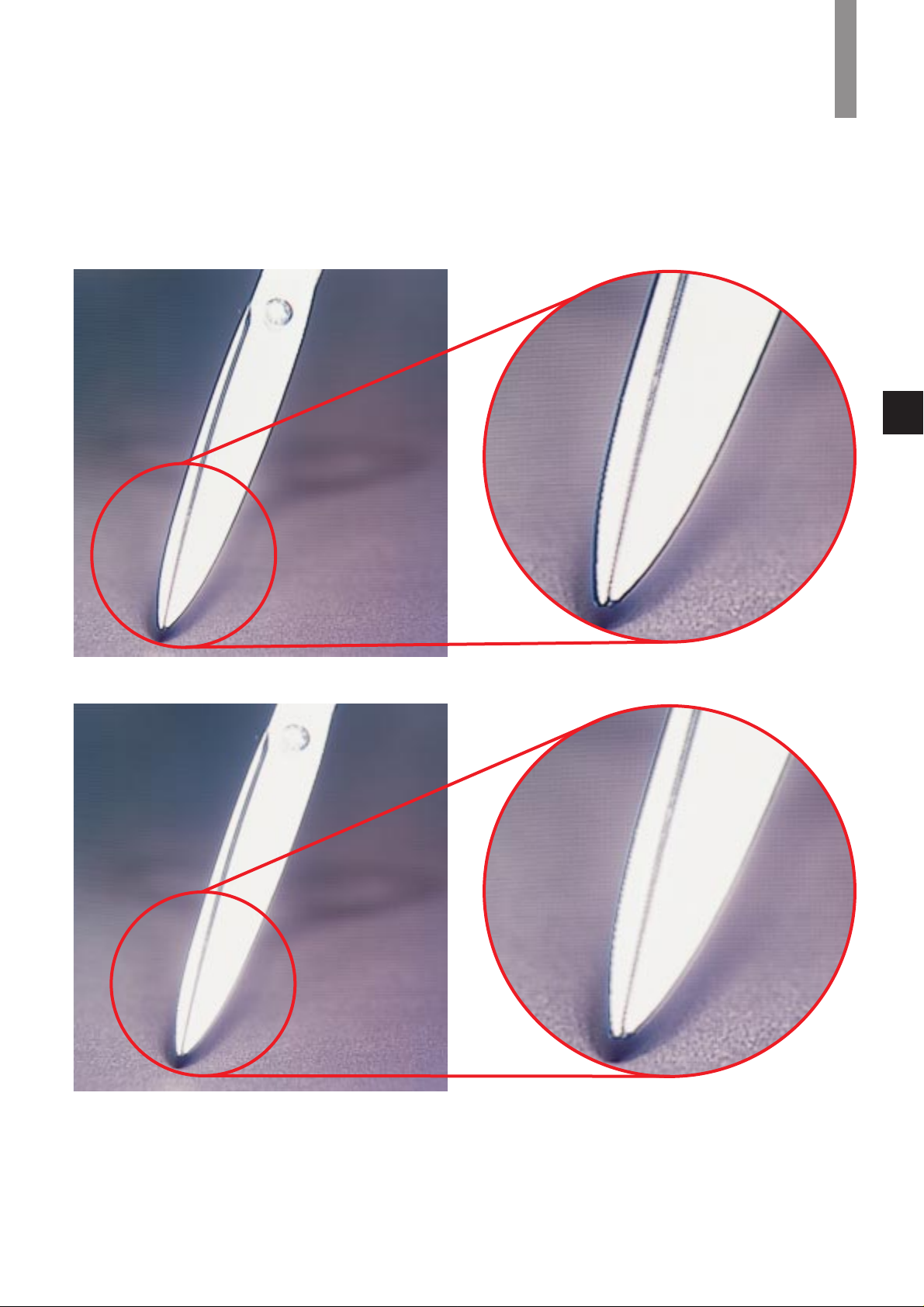
5
BENEFITS OF SONY ADSP
26
(e) Adaptive Detail Control
The Adaptive Detail Control provides natural detail enhancement on
extreme highlights by automatically altering the amplitude of the
edge signal for those forms of high contrast signals.
Photo 5-6 Adaptive Detail Control ON and OFF
Normal Magnified
ON Magnified
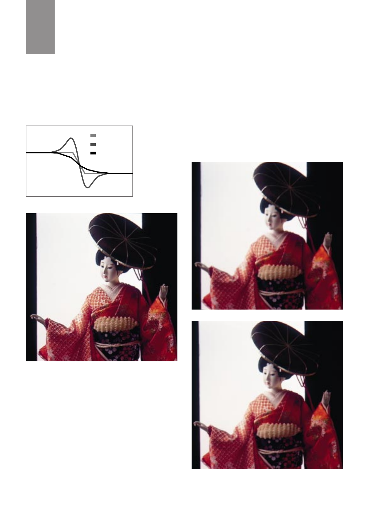
27
5
BENEFITS OF SONY ADSP
(f) Electronic Soft Focus
This function is similar to an optical soft filter. By subtracting the
edge enhancement signal from the original video signal, slight
‘defocussed’ pictures are created electronically. This is an important
new creative feature that can be used to either complement or
replace the Skin Tone Detail Correction function, when more of a
‘film look’ is sought for close-ups, etc.
Original
Enhancer
Soft Focus
Figure 5-5 Electronic Soft Focus signal image
Normal
Electronic Soft Focus ON
Detail off
Photo 5-7 Electronic Soft Focus ON and OFF
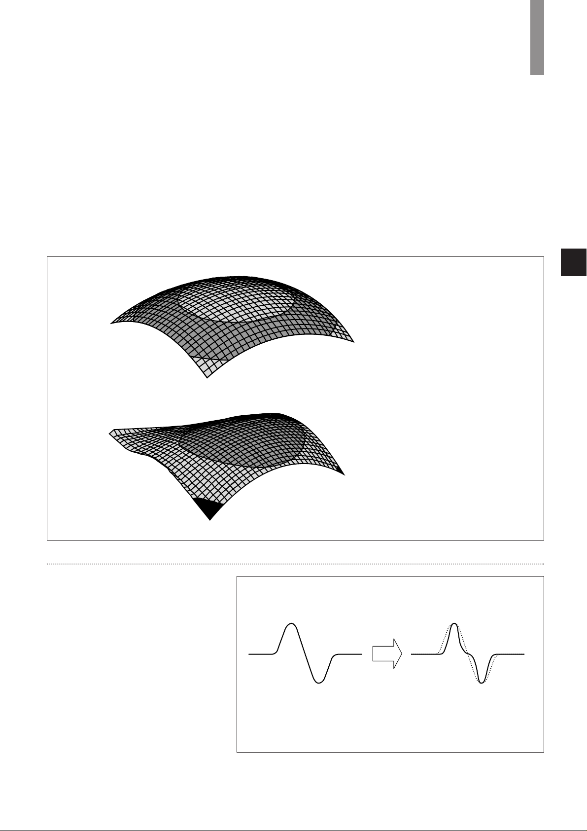
5
BENEFITS OF SONY ADSP
28
(g) Skin Tone Auto Iris
A problem with conventional auto iris is that movements of bright
objects in a scene adversely affects facial exposure – a news studio is
a typical example. Skin Tone Auto Iris is a function that controls the
auto iris system to ensure a constant video level for a defined human
skin area within the scene. In the news studio example, when the
color phase is adjusted to match the facial tones of the news reader,
the iris now maintains the same video level even if the reader turns
the script, or people enter or exit the scene. It is effective for the
other colors in addition to human skin tone.
(h) 3-D White Shading Correction
The camera picture area is divided into up to 1000 separate zones,
each of which may have different shading value. The correction is
automatically interpolated across adjacent zones. This technique
provides precise white shading correction over the whole pictur e
area. The 3D shading mode can be enabled through the camera
maintenance menu, and operates automatically each time white
shading is perfor med. Because the camera ‘learns’ and interpolates
the data the accuracy may be improved still further on subsequent
auto shading operations. White shading data should be stored in the
camera OHB file or will other wise be lost when the camera power is
turned off.
Conventional Correction
3D Shading Correction
Figure 5-6 Correction curve image
(j) Fine Detail
The Fine Detail function allows the width of the
detail edge to be adjusted without changing the peak
level.*
*Effective for H details only.
fine DTL off fine DTL on
Figure 5-7 Signal curve image

5
BENEFITS OF SONY ADSP
29
5-3. Outstanding reliability and easy maintenance
One of the most important concerns for broadcasters is the reliability
of equipment. This is considerably improved with Sony digital
processing. In Sony ADSP cameras all the processing parameters are
completely and precisely defined at the design stage, and almost all
the potentiometers are replaced by semiconductor memories.
Consequently, Sony ADSP cameras show extremely stable
perfor mance, regar dless of environmental conditions such as
temperature, humidity, shock and vibration. This high stability,
together with the advantages of the self-contained menu system,
enables the accurate set-up of camera systems easily for regular
realignment to maintain. Finally, a great merit of Sony ADSP cameras
is their advanced self-diagnostic system. BVP-900 Series cameras
detect problems in their digital processing and provide viewfinder
warning indication. Detailed information, such as identifying the
faulty board, is also shown on the Master Set-up Unit screen and the
Camera Command Network Unit character display to provide easy
and rapid fault location.
5-4. Low power consumption
To achieve its design aim of complete digital processing, including
digital implementation of the non-linear processing stages, Sony has
developed VLSIs which contain over 1,600,000 actual gates. This
complexity demonstrates the advances that Sony has made in the
application of its semiconductor technology. Despite this complexity,
Sony ADSP cameras approach the same low power consumption as
previous analog portable cameras. This has been made possible by
using the Sony EDA (Electronic Design Automation) system to
optimize the complex camera circuitr y in a short time scale and to
incorporate the latest LSI technologies (2.5 V drive and 0.35 µm
design rule) to give a total power consumption of just 20 W for the
BVP-950/950P portable camera with an OHB-730 CCD block
installed.
 Loading...