

Sony BVP-950, BVP-950WSPK, BVP-950P Operation Manual

COLOR VIDEO CAMERA
BVP-950/950P/
950WSPK
OPERATION MANUAL
1st Edition (Revised 2)
Serial No. 10001 and Higher (UC)
Serial No. 15001 and Higher (UC)
Serial No. 40001 and Higher (CE)
Serial No. 45001 and Higher (CE)
[English/German]

English
WARNING
To prevent fire or shock hazard, do not
expose the unit to rain or moisture.
To avoid electrical shock, do not open the
cabinet. Refer servicing to qualified
personnel only.
For the customers in the USA
This equipment has been tested and found to comply
with the limits for a Class A digital device, pursuant to
Part 15 of the FCC Rules. These limits are designed to
provide reasonable protection against harmful
interference when the equipment is operated in a
commercial environment. This equipment generates,
uses, and can radiate radio frequency energy and, if not
installed and used in accordance with the instruction
manual, may cause harmful interference to radio
communications. Operation of this equipment in a
residential area is likely to cause harmful interference in
which case the user will be required to correct the
interference at his own expense.
You are cautioned that any changes or modifications not
expressly approved in this manual could void your
authority to operate this equipment.
The shielded interface cable recommended in this
manual must be used with this equipment in order to
comply with the limits for a digital device pursuant to
Subpart B of Part 15 of FCC Rules.

Table of Contents
English
Overview.............................................................................................2 (E)
Features........................................................................................... 2 (E)
File System ..................................................................................... 3 (E)
Optional Accessories ...................................................................... 4 (E)
Location and Function of Parts........................................................5 (E)
Side Panels...................................................................................... 5 (E)
Front Panel ..................................................................................... 8 (E)
Setting Up the Camera ...................................................................... 9 (E)
Mounting a CCD Unit .................................................................... 9 (E)
Attaching a Lens to the Camera ................................................... 10 (E)
Attaching a 1.5-inch/2-inch Viewfinder ....................................... 11 (E)
Attaching the CA-530/550/550P/570/570P Camera Adaptor ...... 12 (E)
Attaching the CA-553/553P Camera Adaptor.............................. 13 (E)
Attaching the CA-3/3P/3A/3AP Camera Adaptor........................ 13 (E)
Attaching the BVV-5/5PS Videocassette Recorder...................... 14 (E)
Mounting the Camera to a Tripod ................................................ 15 (E)
Specifications.................................................................................... 16 (E)
Manuals for the BVP-900-series video camera system
Three types of manuals are provided for the BVP900-series video camera system: an Operation
Manual, a Maintenance Manual, and a System
Manual. The Operation and Maintenance Manuals
are provided for each device used in the system, and
the System Manual is provided as an option.
In the Operation Manual, specific functions and
characteristics of the device, such as features,
functions of each part and specifications, are
described.
In the Maintenance and System Manuals, you will
find general information on the system, such as
possible system configurations, the setup method,
connections, and system preparations and
operations.
1 (E)

Overview
The BVP-950/950P Color Video Camera is a portable
camera head designed for a Sony BVP-900-series
CCD camera system for studio and outdoor broadcast
applications. The BVP-900-series video camera
system is composed of several independent units like a
pickup device, camera head, camera control unit, video
selector, master setup unit, remote control panel, etc.
So a wide variety of systems is available for your
special purposes.
The CNU-700 Camera Command Network Unit
enables a system to control up to 96 video cameras.
Features
Easy-to-change CCD unit
The CCD unit is a separate block from the camera
head so you can easily change the aspect ratio (4:3 or
16:9) simply by replacing the unit. No readjustment is
required after the change under normal operating
conditions.
Superior performance
Newly developed LSI: A newly developed digital
signal processing LSI and a 12-bit A/D converter
provide various functions and assure a high-quality
picture.
High signal-to-noise ratio: A high signal-to-noise
ratio has been achieved by use of a top-performing
CCD, excellent circuitry, and electronic packaging
technology.
Wide dynamic range: Automatic and manual control
capabilities for knee point and knee slope enables
you to reproduce high-luminance subjects clearly in
up to 600% normal light.
High sensitivity: A sensitivity of F8 at 2,000 lux
(typical) has been achieved. When the video gain
is raised by 18 dB, a video level of 100% is
obtained with minimum subject illuminance of 7.5
lux.
High vertical resolution: The vertical resolution can
be improved to 450 lines for the BVP-950 or to 550
lines for the BVP-950P using the EVS (Enhanced
Vertical Definition System) function. The super
EVS function enables you to adjust vertical
resolution to the desired value between 350 and 450
lines for the BVP-950 (only with the OHB-750A/
750WSA CCD Unit) or between 450 and 550 lines
for the BVP-950P (only with the OHB-750AP/
750WSAP CCD Unit).
Automatic setup and filing function
Built-in microcomputers allow quick and precise
automatic setup, and also reduce the time required for
maintenance. The adjusted data can be stored in the
camera using a filing function.
Electronic shutter
1
An electronic shutter of 6 speeds (from
to 1/2000) is provided with the BVP-950/950P. You
can shoot a rapidly moving object clearly by selecting
the optimal shutter speed. It also has an ECS
(Extended Clear Scan) function. Using this function,
you can adjust the shutter speed of the BVP-950 in 510
1
steps (from
that of the BVP-950P in 607 steps (from
and from 1/50 to 1/9000). Appropriate shutter-speed
selection using the ECS function enables you to
minimize horizontal streaks when shooting a computer
display screen.
Self-diagnostic functions
The BVP-950/950P has self-diagnostic functions to
facilitate troubleshooting.
Display capability
The BVP-950/950P displays the zoom position, the
setting status of a camera, and the warning messages
on the viewfinder screen in characters generated by a
built-in character generator. A center marker, and
safety zone are also displayed on the viewfinder
screen.
Optional 1.5-, 2- or 5-inch viewfinder
attachable
A 1.5-inch BVF-10/10CE Black-and-White
Viewfinder, BVF-C10W Color Viewfinder, or 2-inch
BVF-20W/20WCE Black-and-White Viewfinder can
be attached to the BVP-950/950P.
When the CA-530/550/550P/570/570P Camera
Adaptor is attached to the camera, a high-resolution
5-inch BVF-55/55CE Black-and-White Viewfinder
can also be used.
Compact, lightweight, and power-saving
design
The BVP-950/950P has a compact, lightweight, and
low-power consumption design, which are basic
requirement for outdoor broadcasting.
/30 to 1/58.3 and from 1/60 to 1/7000), and
/100
1
/25 to 1/48.7
2 (E)

File System
The BVP-950/950P can store the adjustment data in
one of the following files.
Reference file
The reference file stores the reference values used for
automatic setup adjustment and the standard settings of
the switches.
Scene files
Scene files store paint data for each scene. For
example, if you store data prepared in rehearsal for a
particular scene in a scene file, the data can be
retrieved to reproduce the same camera settings used in
rehearsal.
Lens files
Lens files store specific data for a lens to be used.
When you use a recommended lens, the standard
values are stored in a lens file at the factory.
OHB files (stored in the CCD unit)
OHB files store specific data for a CCD unit to be
used. The standard values are stored in an OHB file at
the factory.
Creation, storage and retrieval of files are performed
using an optional MSU-700 Master Setup Unit or
RCP-700-series Remote Control Panel. The type and
number of files which can be handled depend on the
unit used.
For details, refer to the System Manual.
3 (E)
Overview
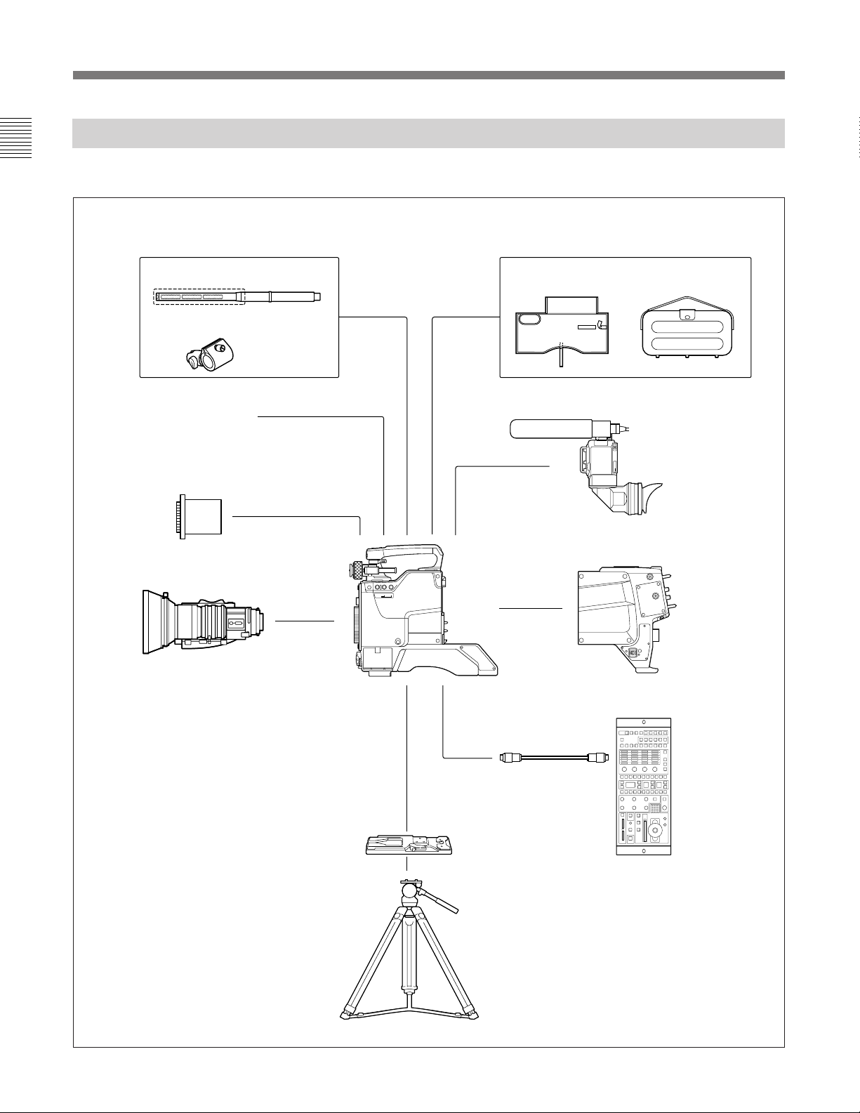
Optional Accessories
The following optional accessories are available.
Microphone
CAC-12 Microphone Holder
Front cover (supplied)
OHB-750A/750WSA/730/730WS/
750AP/750WSAP/730P/730WSP
CCD Unit
Zoom lens
Water-resist cover Carrying case
BVF-10/10CE/C10W
1.5-inch Viewfinder
or BVF-20W/20WCE
2-inch Viewfinder
BVP-950/950P
Color Video Camera
CA-530
FILTER
ND CC
LOCAL
CA-550/550P
CA-570/570P
Camera Adaptor
Caution
It is recommended to use the BVP-950/
950P in combination with the CA-570/
570P Camera Adapter.
If the BVP-950/950P is used with the
CA-550/550P, powering up may not be
executed correctly, depending on the
CA-550/550P version.
If you wish to use the CA-550/550P
instead, please contact your Sony
service representative.
4 (E)
VCT-14
Tripod Adaptor
Tripod
S
CCA-5 cable
(or the cable
supplied with
the RM-B150)
RCP-700-series
Remote Control Panel
(or RM-B150
Remote Control Unit)
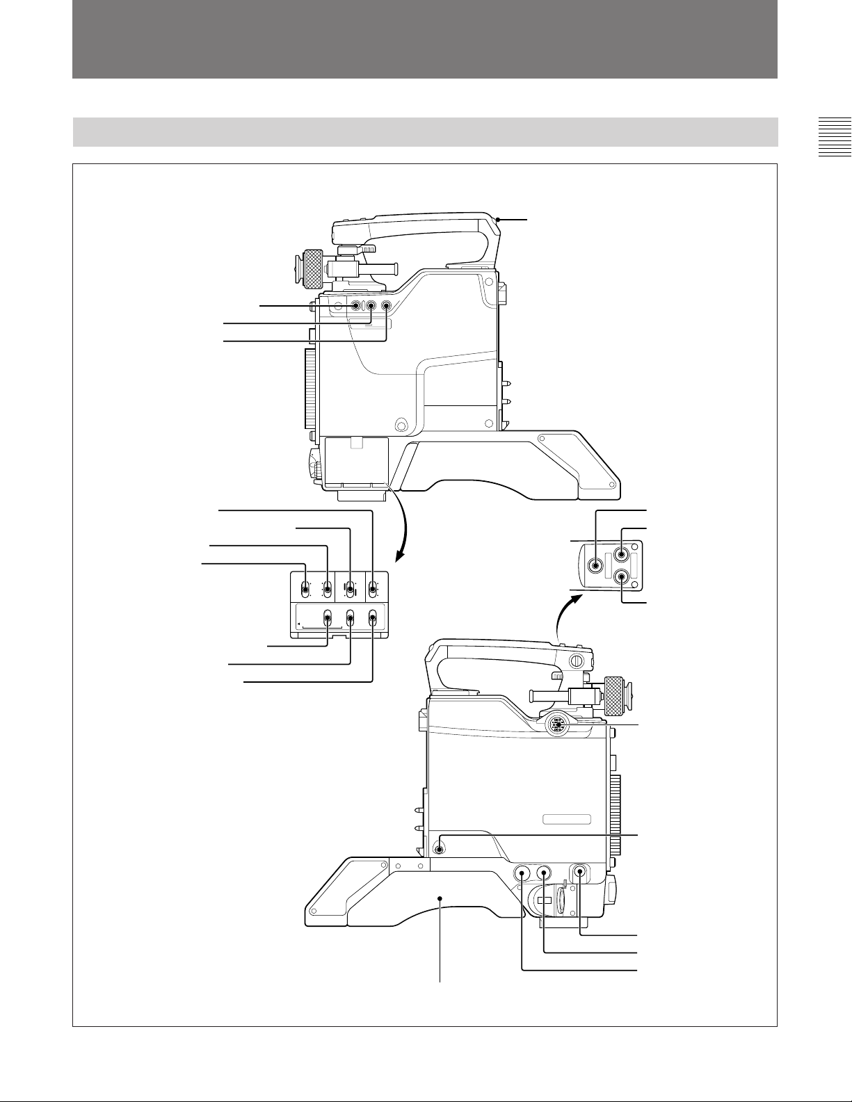
Location and Function of Parts
Side Panels
!¡TALLY lamp and switch
1FILTER LOCAL button
2ND filter button
3CC filter button
4WHITE switch
5OUTPUT/AUTO KNEE switch
6GAIN switch
7VTR switch
8ENTER/CANCEL switch
9DISPLAY switch
0TEST OUT selector
FILTER
ND CC
LOCAL
BLK WHITE
!™INCOM button
!£RET 1 button
RET1 RET2
INCOM
OUTPUT AUTO
VTR
GAIN
STBY
L
M
H
SAVE
ENTER
CANCELSEL
KNEE
CAM
BARSONOFF
DISPLAY TESTOUT
ON
OFF
MENU
WHITE
B
A
PRE
SET
ENC
RGB
SEL
!¢RET 2 button
TEST OUT RET14LOCK REMOTE
@ºShoulder pad
VF
S
Power HAD 1000
MIC1
!∞VF connector
!§LOCK screw
!¶RET 1 button
!•REMOTE connector
!ªTEST OUT connector
5 (E)

Location and Function of Parts
1 FILTER LOCAL (filter local control) button
Press the CC or ND filter button while pressing this
button to enable switching of the CC and ND filters.
2 ND filter button
Selects the desired ND filter while pressing the
FILTER LOCAL button.
Filter No. Filter
1 Clear
2
3
4
5
1
/4 ND
1
/8 ND
1
/16 ND
1
/64 ND
3 CC (color temperature conversion) filter button
Selects the desired CC filter suitable for the lighting
conditions while pressing the FILTER LOCAL button.
Filter No. Filter
A Cross filter
B 3200K (Clear)
C 4300K
D 6300K
E 8000K
4 WHITE (white balance memory select) switch
Selects the white balance adjustment method and
memory to store the adjusted value.
PRESET: White balance is automatically adjusted to
the preset value for the color temperature of 3200K.
A or B: Memory A or B is selected.
6 GAIN switch
Selects the appropriate video gain according to the
illumination of the subject to be shot. The values for
positions L, M, and H are set with the Setup Menu on
the viewfinder screen.
For details, refer to the System Manual.
7 VTR switch
Selects the control signal for the VTR when the VTR
is connected to this unit using the optional CA-553/
553P Camera Adaptor. According to the setting of this
switch, the VTR starts recording as follows:
SAVE: Power-save position for recording. Recording
starts a few seconds after the VTR START button
is pressed. A newly recorded picture may not
smoothly be connected to the previously recorded
part.
STBY (standby): Recording starts immediately upon
pressing the VTR START button.
Note
The WHITE 4, OUTPUT/AUTO KNEE 5, GAIN 6,
and VTR 7 switches do not function when the camera
is connected to a Camera Control Unit (CCU).
8 ENTER/CANCEL switch
Functions when the DISPLAY switch is set to MENU
(Menu mode).
ENTER: Activates the selection made by the MIC 1
LEVEL control.
CANCEL: Cancels the selection made by the MIC 1
LEVEL control and restores the previously selected
menu item.
5 OUTPUT/AUTO KNEE (output signal select/
auto knee) switch
Selects an output signal supplied to a VTR, viewfinder
and video monitor (color bar signals or camera
picture). When a camera picture is selected, the auto
knee function can be activated.
BARS/OFF: Color-bar signals are output, and the
auto-knee circuit does not function.
CAM/OFF: A camera picture is output, but the auto-
knee circuit does not function.
CAM/ON: A camera picture is output, and the auto-
knee circuit functions.
6 (E)
For menu operations, refer to the System Manual.
9 DISPLAY switch
Used for displaying the camera status such as switch
settings, items and results of automatic adjustments on
the viewfinder screen.
ON: Display function is activated.
OFF: Display function is not activated.
MENU: A screen for setting the displaying items and
functions appears. The MIC 1 LEVEL control on
the front panel functions as the menu item selector.
For menu operations, refer to the System Manual.
0 TEST OUT (output) selector
Selects the output signal from the TEST OUT
connector.
ENC: An encode signal is output.
RGB: Either R, G or B signal is output.
SEL: Each time you press down the switch from the
RGB position towards this position, the output
signal from the TEST OUT connector cyclically
changes between R, G and B.
!¡ TALLY (back tally) lamp and switch
With the switch set to ON, the lamp lights in the
corresponding color when a red or green tally signal is
supplied.
When the CALL button on the MSU-700 or RCP-700series unit is pressed, the lamp lights if not lit, and
goes out if lit.
When a VTR is connected to the camera using a
camera adaptor, the lamp lights in red when a rec tally
signal is supplied from the VTR.
To keep the lamp off even when a tally signal is
supplied, set the switch to OFF.
!™ INCOM (intercom) button
The intercom 1 microphone is turned ON while this
button is pressed.
!¶ RET 1 (return video 1) button
A return video 1 signal from the Camera Control Unit
(CCU) is monitored on the viewfinder screen while
this button is pressed. It is the same function as with
the other RET 1 button !£.
!• REMOTE connector (8-pin)
Connect an optional RCP-700-series Remote Control
Panel or RM-B150 Remote Control Unit by using a
CCA cable.
The camera can be controlled from the unit connected
via this connector.
Using the exclusive cable supplied with the RM-B150,
a video signal for monitoring can be output from the
RM-B150.
!ª TEST OUT connector (BNC type)
Supplies the signal selected with the TEST OUT
selector.
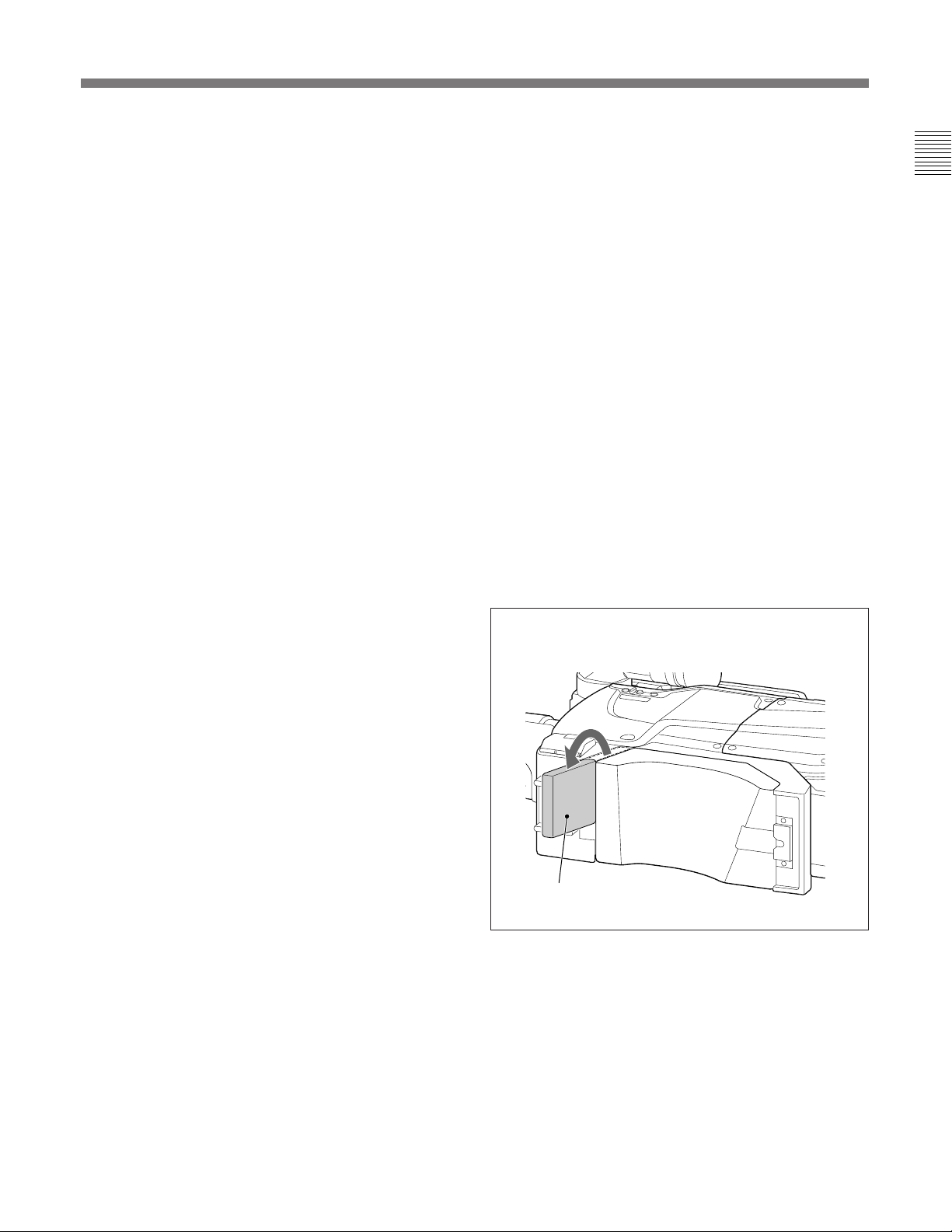
@º Shoulder pad
You can also use the small pad as the chest pad while
pulling it out.
To pull out the chest pad
!£ RET 1 (return video 1) button
A return video 1 signal from the Camera Control Unit
(CCU) is monitored on the viewfinder screen while
this button is pressed. It is the same function as with
the other RET 1 button !¶.
!¢ RET 2 (return video 2) button
Press this button when another return video system
(return video 2) is used. Then the return video 2 signal
can be monitored on the viewfinder screen.
!∞ VF (viewfinder) connector (20-pin)
Connect the 20-pin viewfinder cable of an optional
viewfinder. To use the BVF-55/55CE Viewfinder,
connect the cable supplied with the viewfinder.
!§ LOCK screw
To lock the attached camera adaptor.
Chest pad
7 (E)

Location and Function of Parts
Front Panel
2 Microphone power switch
1 MIC 1 connector
VTR
AUTO
SHUTTER
MIC1
W/B BAL
LEVEL
WHT
BLK
OFF +48V
START
OFF
ON
LENS
SEL
7 MIC 1 LEVEL control
6 AUTO W/B BAL switch
5SHUTTER switch
4VTR START button
3 LENS connector
with the Setup Menu displayed on the viewfinder
screen so that the audio signal of intercom 1 or 2 or the
return video 2 signal is sent to the CCU while this
button is kept pressed.
For details, refer to the System Manual.
When a VTR is connected using the CA-553/553P,
pressing this button starts recording, and pressing
again stops recording. It is the same function as with
the VTR button on the lens.
5 SHUTTER switch
OFF: An electronic shutter does not function.
ON: An electronic shutter is activated.
SEL: The shutter speed and shutter mode change each
time the switch is set to this position.
For details, refer to the System Manual.
6 AUTO W/B BAL (automatic white balance/
black balance adjustment) switch
Adjusts the white balance and black balance
automatically.
WHT: The white balance is automatically adjusted.
When the WHITE switch on the side of the camera
is set to A or B, the adjusted value is stored in
memory A or B.
BLK: The black balance is automatically adjusted.
The black set is simultaneously adjusted.
1 MIC 1 (microphone channel 1) connector
Accepts the signal of microphone channel 1.
Normally, connect the microphone supplied with the
optional BVF-10/10CE, BVF-C10W or BVF-20W/
20WCE Viewfinder.
2 Microphone power switch
For the microphone connected to the MIC-1 connector.
+48 V: When the microphone supplied with the
optional BVF-10/10CE, BVF-C10W or BVF-20W/
20WCE Viewfinder is connected.
A power of +48 V is supplied to the microphone.
OFF: When the connected microphone requires no
external power.
3 LENS connector (12-pin)
Connect a lens cable.
4 VTR START button
When the Camera Control Unit (CCU) is connected
using the optional camera adaptor, the audio signal of
intercom 1 is sent to the CCU while this button is kept
pressed. The function of this button can be changed
Note
The SHUTTER5 and AUTO W/B BAL6 switches
do not function when the camera is connected to the
camera control unit (CCU).
7 MIC 1 LEVEL (microphone 1 level) control
When a VTR is connected using the optional camera
adaptor, the microphone 1 audio level can be adjusted
by turning this control.
When the CA-570/570P Camera Adaptor is used and
the LEVEL/MIC switch on the rear panel of the
camera adaptor is set to FRONT/OFF, adjust the sound
volume of the intercom with this control. You can also
turn on/off the intercom 1 microphone by pressing this
control.
When the DISPLAY switch on the side panel of this
camera is set to MENU, turn this control to select a
menu item and press it to register the selection.
For menu operations, refer to the System Manual.
8 (E)
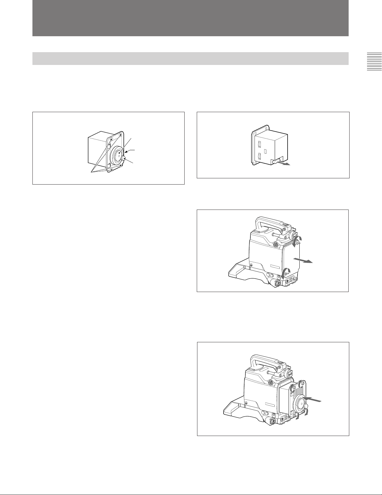
Setting Up the Camera
Mounting a CCD Unit
Any of the following CCD units can be mounted to the
camera.
BVP-950: OHB-750A/750WSA/730/730WS
BVP-950P: OHB-750AP/750WSAP/730P/730WSP
CCD unit
Mounting cap
Connector cover
(on the rear)
Mounting lever
Mounting screws
Mounting procedure
1 Remove the red connector cover from the rear of
the CCD unit.
2 Loosen two screws on the front panel, and remove
the front panel.
S
Power HAD
1000
3 Insert the CCD unit, and secure it with the four
mounting screws.
Fasten the screws securely with a coin or similar
tool.
S
Power HAD
1000
9 (E)
Setting Up the Camera
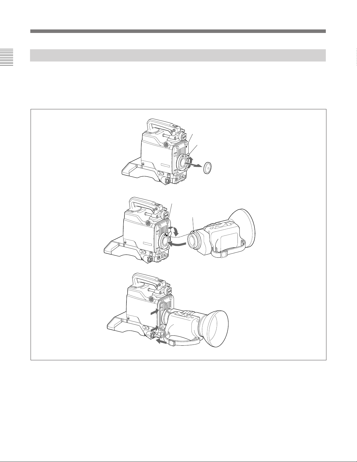
Attaching a Lens to the Camera
Attach an optional lens as described below.
For details on the lens, refer to the instruction manual
furnished with the lens.
Attaching procedure
RET1
CCD unit
S
Power HAD
1000
S
S
Power HAD
1000
Mounting lever
Mounting cap
1
Recess
Center pin
3
2
Power HAD
1000
5
4
1 Turn the mounting lever on the CCD unit fully
counterclockwise, and remove the mounting cap.
2 Align the center pin of the lens with the recess at
the top of the lens mount section, and insert the
lens to the camera.
10 (E)
3 Turn the mounting lever fully clockwise to fix the
lens while holding the lens.
4 Connect the lens cable to the LENS connector.
5 Fix the cable with the cable clamps.
 Loading...