

Sony BVP-900 Series, BVP-900, BVP-900P, BVP-950, BVP-950P System Manual
BVP-900 Series Video Camera System
SYSTEM MANUAL
BVP-900 Series
Video Camera
1st Edition (Revised 1)
System
SYSTEM MANUAL
1st Edition (Revised 1)
MADE IN JAPAN

BVP-900 Series
Video Camera
System
SYSTEM MANUAL
1st Edition (Revised 1)
English


Table of Contents
About This Manual..................................................................................vii
Chapter 1
Introduction
Chapter 2
Setup
1-1 Overview of the Camera System.................................................... 1-1
1-1-1 Features .................................................................................. 1-1
1-1-2 File System............................................................................. 1-2
1-2 Configuration of the BVP-900-series Camera System................ 1-3
1-2-1 System Configuration ............................................................ 1-3
1-2-2 Example When a BVP-900/900P Is Used
as a Stand-Alone Camera....................................................... 1-5
1-2-3 Example When a BVP-950/950P Is Used
as a Stand-Alone Camera....................................................... 1-6
1-2-4 Example When a BVP-950/950P Installed
in a CA-905F/905K Is Used................................................... 1-7
1-2-5 Camera System Using a Camera Control Unit ...................... 1-9
1-2-6 System To Control up to Six BVP-900-series Cameras...... 1-10
1-2-7 System To Control up to 12 BVP-900-series Cameras
Using the CNU-700 ............................................................. 1-11
1-2-8 System To Control up to 24 BVP-900-series Cameras
Using the CNU-700 ............................................................. 1-12
1-2-9 Control System of the CNU-700/500................................... 1-13
1-2-10 S-BUS Control System Using the CNU-700..................... 1-18
1-2-11 System to Convert the Aspect Ratio.................................. 1-24
2-1 Mounting the Video Camera ......................................................... 2-1
2-1-1 Mounting the BVP-900/900P................................................. 2-2
2-1-2 Mounting the BVP-950/950P................................................. 2-9
2-1-3 Mounting the CA-905F/905K.............................................. 2-18
2-1-4 Attaching the Number Plate................................................. 2-24
2-2 Rack Mounting ............................................................................. 2-25
2-3 Connections ................................................................................... 2-28
2-3-1 Basic Signal Connections..................................................... 2-28
2-3-2 Cable Connections ............................................................... 2-31
Chapter 3
Initial Settings
(Continued)
3-1 Internal Boards............................................................................... 3-1
3-1-1 Internal Boards of the BVP-900/900P................................... 3-1
3-1-2 Internal Boards of the BVP-950/950P................................... 3-6
3-1-3 Internal Board of the CA-530 ................................................ 3-8
3-1-4 Internal Boards of the CA-550/550P ..................................... 3-9
3-1-5 Internal Boards of the CA-570/570P ................................... 3-12
3-1-6 Internal Boards of the CCU-700A/700AP........................... 3-17
3-1-7 Internal Boards of the CCU-550A/550AP............................ 3-26
3-1-8 Internal Board of the VCS-700............................................ 3-35
3-1-9 Internal Boards of the CNU-700.......................................... 3-36
3-1-10 Internal Board of the CNU-500 ......................................... 3-38
3-1-11 Internal Board of the ARU-701 .......................................... 3-39
3-1-12 Internal Board of the ARU-702 .......................................... 3-41
Table of Contents i

Table of Contents
Chapter 3
Initial Settings (Continued)
3-2 Setting and Adjusting on Setup .................................................. 3-43
3-2-1 Settings for the Intercom Systems ....................................... 3-43
3-2-2 Setting for the Tally System ................................................ 3-52
3-2-3 Settings for Tally Call.......................................................... 3-53
3-2-4 Adjusting the Program Microphone Signal ......................... 3-54
3-2-5 Setting the Camera Number and Group Number ................ 3-57
3-2-6 Setting the Station ID .......................................................... 3-59
3-2-7 Setting the Broadcasting System ......................................... 3-59
3-2-8 Selecting the Aspect Ratio................................................... 3-60
3-2-9 Setting the Character Display of the CNU-700 ................... 3-60
3-2-10 Initial Settings of the Camera ............................................ 3-61
3-3 Checking and Adjusting the Signal of the System ..................... 3-63
3-3-1 Resetting the Control Data................................................... 3-63
3-3-2 Adjusting the Phases of the Signals ..................................... 3-66
3-3-3 Checking and Adjusting the VBS Signal Level................... 3-70
3-3-4 Adjusting the Triax Signal ................................................... 3-72
3-3-5 Adjusting the Signal of the Optional Boards ....................... 3-77
3-3-6 Selecting and Adjusting the Signal on a Waveform
Monitor................................................................................. 3-80
3-3-7 Selecting and Adjusting the Signal on a Picture Monitor.... 3-83
3-3-8 Setting the Mix Ratio of the Character Signal and the
Video Signal......................................................................... 3-85
3-3-9 When Adjustments Are Finished......................................... 3-86
3-4 Initial Settings for the Control System....................................... 3-87
3-4-1 Specifying the Security Code .............................................. 3-87
3-4-2 Setting the Security Status ................................................... 3-90
3-4-3 MSU Assignment ................................................................ 3-91
3-4-4 Setting the Operating Conditions of the MSU..................... 3-94
Chapter 4
Adjustments
4-1 Control Functions........................................................................... 4-1
4-1-1 Function Table ....................................................................... 4-1
4-1-2 MSU-700A/750 Menu Items ................................................. 4-5
4-1-3 Controller Layouts ............................................................... 4-13
4-2 Preparations for Adjustments..................................................... 4-19
4-2-1 Power Supply ....................................................................... 4-19
4-2-2 Setting the Control Priority .................................................. 4-20
4-2-3 RCP Assignment .................................................................. 4-22
4-2-4 Setting the Master/Slave Units............................................. 4-26
4-2-5 Selecting the Test Signal...................................................... 4-27
4-2-6 Selecting Monitor Signals.................................................... 4-28
4-3 Basic Adjustment Operations ..................................................... 4-30
4-3-1 MSU-700A/750 Basic Operations ....................................... 4-30
4-3-2 RCP-Series Basic Operations .............................................. 4-32
4-4 Black Adjustments ....................................................................... 4-34
4-4-1 Adjusting the Black Shading................................................ 4-34
4-4-2 Adjusting the Black Set........................................................ 4-36
4-4-3 Adjusting the Black Balance................................................ 4-37
4-4-4 Adjusting the Master Black.................................................. 4-39
ii Table of Contents

Chapter 4
Adjustments (Continued)
4-5 Iris Adjustments ........................................................................... 4-40
4-5-1 Automatic Adjustment......................................................... 4-40
4-5-2 Manual Adjustment ............................................................. 4-41
4-5-3 Closing Function.................................................................. 4-42
4-5-4 Auto Iris Setup..................................................................... 4-43
4-6 White Adjustments....................................................................... 4-46
4-6-1 Selecting the Filters ............................................................. 4-46
4-6-2 Selecting the Master Gain.................................................... 4-48
4-6-3 Adjusting the White Balance ............................................... 4-49
4-6-4 Adjusting the V Modulation Compensation ........................ 4-51
4-6-5 Adjusting the White Shading............................................... 4-52
4-6-6 Adjusting the White Clip ..................................................... 4-54
4-7 Gamma Adjustments ................................................................... 4-56
4-7-1 Selecting the Step Gamma.................................................... 4-56
4-7-2 Adjusting the Gamma Level................................................ 4-56
4-7-3 Adjusting the Black Gamma................................................ 4-59
4-8 Flare Adjustment ......................................................................... 4-62
4-9 Knee Adjustments ........................................................................ 4-64
4-9-1 Adjusting the Knee .............................................................. 4-64
4-9-2 Adjusting the Auto Knee ..................................................... 4-68
4-9-3 Adjusting the Knee Saturation............................................. 4-71
4-10 Detail Adjustments..................................................................... 4-73
4-11 Skin Detail Adjustments ............................................................ 4-77
4-12 Matrix Adjustments ................................................................... 4-80
4-13 Super-EVS Adjustment ............................................................. 4-83
4-14 Shutter Speed Selection ............................................................. 4-84
4-15 Chroma Off and Saturation / Contrast Adjustments ............. 4-86
4-15-1 Chroma Off Function......................................................... 4-86
4-15-2 Adjusting the Saturation and Contrast............................... 4-86
4-16 Mono Color Adjustment............................................................ 4-89
4-17 Y/C (Sub-Encoder Board) Adjustments (NTSC) .................... 4-91
4-17-1 Adjusting the Color Correctors.......................................... 4-91
4-17-2 Adjusting the EDTV Function........................................... 4-94
4-17-3 Adjusting the Comb Filter ................................................. 4-95
4-18 Notch Adjustment (PAL)........................................................... 4-96
4-19 Auto Setup................................................................................... 4-97
4-19-1 Black Auto Setup............................................................... 4-97
4-19-2 White Auto Setup .............................................................. 4-98
4-19-3 Level Auto Setup ............................................................... 4-99
4-19-4 Skin Detail Hue Auto Setup .............................................. 4-99
4-19-5 Black Shading Auto Setup............................................... 4-100
4-19-6 White Shading Auto Setup .............................................. 4-100
4-19-7 Auto Setup With the Auto Setup Menu........................... 4-101
4-19-8 Error Messages ................................................................ 4-103
4-20 Retrieval of the Standard Settings.......................................... 4-104
Table of Contents iii

Table of Contents
Chapter 5
File Operations
Chapter 6
Display
5-1 File Configuration .......................................................................... 5-1
5-2 Storing the Reference File ............................................................. 5-4
5-3 Storing the OHB File ..................................................................... 5-8
5-4 Selecting and Modifying the Lens Files...................................... 5-12
5-4-1 Selecting the Lens File (BVP-950/950P) ............................ 5-12
5-4-2 Adjusting the Lens File Data ............................................... 5-15
5-4-3 Changing the Registered Lens ............................................. 5-19
5-5 Storing and Retrieving the Scene Files....................................... 5-22
5-5-1 Storing a Scene File ............................................................. 5-22
5-5-2 Retrieving a Scene File........................................................ 5-23
5-6 File Transfer ................................................................................. 5-24
5-6-1 About IC Memory Cards ..................................................... 5-24
5-6-2 Inserting/Ejecting an IC Card .............................................. 5-24
5-6-3 Initializing the IC Card ........................................................ 5-26
5-6-4 Transferring the Reference File ........................................... 5-27
5-6-5 Transferring the Scene Files ................................................ 5-32
6-1 Display on the Viewfinder Screen of the BVP-900/900P ............ 6-1
6-1-1 Mark Display ......................................................................... 6-1
6-1-2 Character Display ................................................................. 6-2
6-1-3 Operation Menu ..................................................................... 6-3
6-1-4 Maintenance Menu ................................................................ 6-5
6-2 Display on the Viewfinder Screen of the BVP-950/950P ............ 6-6
6-2-1 Mark Display ......................................................................... 6-6
6-2-2 Character Display .................................................................. 6-7
6-2-3 Operation Menu ..................................................................... 6-7
6-2-4 Maintenance Menu ................................................................ 6-9
6-3 Display on the Viewfinder Screen of the BVP-950/950P
Mounted on the CA-905F/905K .................................................. 6-10
6-3-1 Mark Display ....................................................................... 6-10
6-3-2 Character Display ............................................................... 6-11
6-3-3 Operation Menu ................................................................... 6-12
6-3-4 Maintenance Menu .............................................................. 6-15
6-4 Character Display of the CCU-700A/700AP/550A/550AP ....... 6-16
6-4-1 Display of the CCU-700A/700AP ....................................... 6-16
6-4-2 Display of the CCU-550A/550AP ....................................... 6-21
6-4-3 Superimposing Characters in the Color Bar Signals ........... 6-25
6-5 Character Display of the CNU-700/500...................................... 6-26
Chapter 7
Stand-Alone Operations
of Camras, etc.
iv Table of Contents
7-1 Camera Controls for Stand-Alone Usage..................................... 7-1
7-2 Adjustments on the BVP-900/900P............................................... 7-2
7-2-1 Menu Selection ...................................................................... 7-2
7-2-2 Adjustment With the VF Setup 2 Menu................................. 7-3
7-2-3 Adjustments With the Skin Tone Detail Menu...................... 7-4
7-2-4 Adjustments With the Painting Menu.................................... 7-5
7-2-5 Adjustments With the File Control Menu.............................. 7-6
7-2-6 Adjustments With the Shutter Setup Menu............................ 7-7
7-2-7 Adjustments With the Auto Iris Setup Menu......................... 7-8
7-2-8 Adjustments of the BVP-700/700P Upgraded With the BKP-7090/
7090P ..................................................................................... 7-8

Chapter 7
Stand-Alone Operations
of Camras, etc. (Continued)
7-3 Adjustments on the BVP-950/950P............................................... 7-9
7-3-1 Switch Operations.................................................................. 7-9
7-3-2 Auto Setup of the Black Balance/White Balance .................. 7-9
7-3-3 Selecting the Shutter Speed.................................................. 7-10
7-3-4 Menu Selection .................................................................... 7-11
7-3-5 Adjustment With the VF Setup 3 Menu............................... 7-12
7-3-6 Adjustments With the Skin Tone Detail Menu.................... 7-13
7-3-7 Adjustments With the Painting Menu.................................. 7-14
7-3-8 Adjustments With the File Control Menu............................ 7-15
7-3-9 Adjustments With the Shutter Setup Menu ......................... 7-16
7-3-10 Adjustment With the System Setup Menu ........................ 7-17
7-3-11 Adjustment With the Auto Iris Setup Menu ...................... 7-17
7-4 Operation From the RM-B150.................................................... 7-18
7-5 Stand-Alone Use of the VCS-700 ................................................ 7-19
7-5-1 Connection Example............................................................ 7-19
7-5-2 Settings for Stand-Alone Use .............................................. 7-20
7-5-3 Notes on Stand-Alone Use................................................... 7-20
Chapter 8
Specifications
(Continued)
8-1 Dimensions ...................................................................................... 8-1
8-1-1 BVP-900/900P (with the BVF-77/77CE attached)................ 8-1
8-1-2 BVP-950/950P....................................................................... 8-1
8-1-3 OHB-730/750A-series ........................................................... 8-2
8-1-4 CA-530/550/550P/570/570P ................................................. 8-2
8-1-5 CA-905K/905F ...................................................................... 8-3
8-1-6 CCU-550A/550AP................................................................. 8-5
8-1-7 CCU-700A/700AP................................................................. 8-5
8-1-8 CNU-500 ............................................................................... 8-6
8-1-9 CNU-700 ............................................................................... 8-6
8-1-10 VCS-700 .............................................................................. 8-7
8-1-11 MSU-700 ............................................................................. 8-7
8-1-12 MSU-750 ............................................................................. 8-8
8-1-13 RCP-740 .............................................................................. 8-8
8-1-14 RCP-741 .............................................................................. 8-8
8-1-15 RCP-730 .............................................................................. 8-9
8-1-16 RCP-731 .............................................................................. 8-9
8-1-17 RCP-720 .............................................................................. 8-9
8-1-18 RCP-721 .............................................................................. 8-9
8-1-19 RCP-700 ............................................................................ 8-10
8-1-20 RCP-701 ............................................................................ 8-10
8-1-21 ARU-701/701P .................................................................. 8-10
8-1-22 ARU-702/702P .................................................................. 8-10
8-2 Specifications ................................................................................ 8-11
8-2-1 BVP-900/900P..................................................................... 8-11
8-2-2 BVP-950/950P..................................................................... 8-12
8-2-3 CA-530 ................................................................................ 8-13
8-2-4 CA-550/550P ....................................................................... 8-13
8-2-5 CA-570/570P ....................................................................... 8-14
8-2-6 CA-905K/905F .................................................................... 8-14
8-2-7 CCD Units ........................................................................... 8-16
8-2-8 CCU-700A/700AP............................................................... 8-17
8-2-9 CCU-550A/550AP............................................................... 8-18
Table of Contents v

Table of Contents
Chapter 8
Specifications (Continued)
8-2-10 CNU-500 ........................................................................... 8-19
8-2-11 CNU-700 ........................................................................... 8-20
8-2-12 VCS-700 ............................................................................ 8-20
8-2-13 MSU-700 ........................................................................... 8-21
8-2-14 MSU-750 ........................................................................... 8-22
8-2-15 RCP-740/741 ..................................................................... 8-22
8-2-16 RCP-730/731 ..................................................................... 8-23
8-2-17 RCP-720/721 ..................................................................... 8-23
8-2-18 RCP-700/701 ..................................................................... 8-24
8-2-19 ARU-701/701P .................................................................. 8-24
8-2-20 ARU-702/702P .................................................................. 8-26
8-2-21 Optional Accessories ......................................................... 8-27
Index ........................................................................................................I-1
vi Table of Contents

About This Manual
This system manual gives you general information for
the BVP-900-series video camera system, such as the
system configuration, setup method, connections, and
system preparations and operations.
For additional information, please refer to the
operation and maintenance manuals provided with
each machine used in the system. In the operation
manuals, specific functions and characteristics of the
respecive machines, such as their features, functions of
each part and specifications, are described. The
maintenance manuals provide the necessary
information for checking and maintaining the
machines.
Machines explained in this manual
Model number Model name
BVP-900/900P
BVP-950/950P
CA-530
CA-550/550P
CA-553/553P Camera Adaptor
CA-570/570P
CA-3A/3AP
CA-905F/905K Large Lens Adaptor
CCU-550A/550AP Camera Control Unit
CCU-700A/700AP
CNU-500 Camera Command Network Unit
CNU-700
OHB-730/730P
OHB-730WS/730WSP
OHB-750A/750AP
OHB-750WSA/750WSAP
MSU-700A Master Setup Unit
MSU-750
RCP-740/741
RCP-730/731
RCP-720/721
RCP-700/701
RM-B150 Remote Control Unit
VCS-700 Video Selector
Color Video Camera
CCD Unit
Remote Control Panel
About This Manual
Table of Contents vii


1-1 Overview of the Camera System
Chapter 1 Introduction
The BVP-900-series is a video camera systems for
studio and outdoor broadcasting use developed by
Sony. These systems are composed of independent
units which have their own unique functions, allowing
various system configurations in a variety of
combinations of the units. And the command system
developed for the Sony camera system allows flexible
system configuration for creating the required system
in most cases.
The BVP-900-series camera systems have the
following features.
1-1-1 Features
Adaptable to a 16:9 wide screen, thanks to an
independent CCD unit
A CCD block of the camera is designed as a plug-in
type independent unit, so the camera can be used for
shooting in 16:9 wide screen simply by replacing the
CCD block.
Compatibility of a studio camera and portable
camera
The studio camera head and portable camera head use
a common CCD unit and control system of equal
picture quality. This allows you to use both cameras
under the same standards.
Command system for a flexible and
expandible system
The CNU-700 Camera Command Network Unit
developed for this camera system lets you construct a
camera system with up to 96 cameras. This system
opens up many possibilities, such as having one MSU700A/750 Master Setup Unit control multiple cameras,
any RCP-700-series Remote Control Panel control any
BVP-900-series Video Camera.
Newly designed body: The height of the body of the
BVP-900/900P is reduced, allowing wide visual
field, greater convenience of operation, and reduced
parallax between the lens and viewfinder. Large
handles on each side of the cabinet make
transportation and mounting on a tripod easy.
Rotatable triax connector: The triax connector of the
BVP-900/900P and CA-550/550P/570/570P can
rotate for easy cable connection and transportation.
Easy-to-see indications
On the MSU-700A/750 and RCP-700-series units, the
names of buttons and controls are printed beneath, and
LEDs are mounted near the surface of the buttons for
better legibility when installed in a control console.
High picture quality
High horizontal resolution: Horizontal resolution of
900 TV lines of the Y channel is obtained thanks to
the low-smear Power HAD (Hole-Accumulated
Diode)
TM
1000 CCD (Charge-Coupled Device).
High signal-to-noise ratio: High signal-to-noise ratio
is obtained by adopting the high-quality CCD and
superior technology of circuitry and packaging.
Improved vertical resolution: Super EVS (Enhanced
Vertical Definition System)
1)
improves vertical
resolution.
Clear picture: Thanks to the substantial detail-control
functions, a clear picture is obtained.
Wide-band triax system: The bandwidth of the triax
system for a component signal is now 10 MHz for a
Y signal, and 6 MHz for R–Y and B–Y signals.
Electronic shutter
A six-speed electronic shutter is provided with the
camera. You can also set various shutter speeds with
the ECS (Extended Clear Scan)
1)
function. Using this
function, a computer display screen can be shot
clearly.
Chapter 1
Excellent design based on human engineering
The following features have been added for maximum
ease of use.
Compact and lightweight: The camera is compact,
lightweight of low power consumption, and suitable
for use in an OB van.
..........................................................................................................................................................................................................
1) The EVS and ECS function only on the OHB-750A/
750WSA-series CCD.
Auto setup function
With the microcomputer-controlled auto setup
function, auto white balance, auto black balance and
auto level adjustments can be executed accurately and
quickly.
Chapter 1 Introduction 1-1

1-1 Overview of the Camera System
Chapter 1
Power HAD sensor CCD units to suit each
purpose
Each of the optional CCD units incorporates an Power
HAD sensor CCD with 520,000 pixels to achieve high
image quality. The various CCD units share the
following characteristics:
• High sensitivity: 2000 lx (F8)
• High signal-to-noise ratio
NTSC: 65 dB (typical)
PAL: 63 dB (typical)
• Very low smear
• Very low flare
The following optional CCD units are available:
• OHB-730/730P: IT type
• OHB-730WS/730WSP: 16:9 aspect ratio, IT type
(16:9/4:3 switchable)
• OHB-750A/750AP: FIT type
• OHB-750WSA/750WSAP: 16:9 aspect ratio, FIT
type (16:9/4:3 switchable)
White shading and other compensation data are stored
within each CCD unit, thus eliminating the need for
readjustments after replacement of CCD units for
upgrades or repairs, etc.
1-1-2 File System
The BVP-900-series camera system has the capability
of storing the adjustment data in one of the following
files, for quick setup and simpler operation. The
stored data can be recalled as desired, and be
transmitted to other cameras.
This system can control the following four kinds of
files.
Reference file (stored in the camera head)
The reference file stores the reference values used for
automatic setup adjustment and the standard settings of
the switches.
Scene files (stored in the camera head)
Scene files store paint data for each scene. For
example, if you store data prepared in rehearsal for a
particular scene in a scene file, the data can be
retrieved to reproduce the same camera settings as
used in rehearsal.
Lens files (stored in the camera head)
Lens files store specific data for a lens to be used. For
the recommended lens, the standard values are stored
in a lens file at the factory.
OHB files (stored in the CCD unit)
OHB files store specific data for a CCD unit to be
used. The standard values are stored in an OHB file at
the factory.
Creations, storage and retrieval of files are performed
using a MSU-700A/750 Master Setup Unit, RCP-700series Remote Control Panel or menu of the BVP-900/
950-series camera system. The type and number of
files which can be handled depend on the used unit.
For details, see “Chapter 5 File Operations.”
1-2 Chapter 1 Introduction
1-2 Configuration of the BVP-900-series Camera System
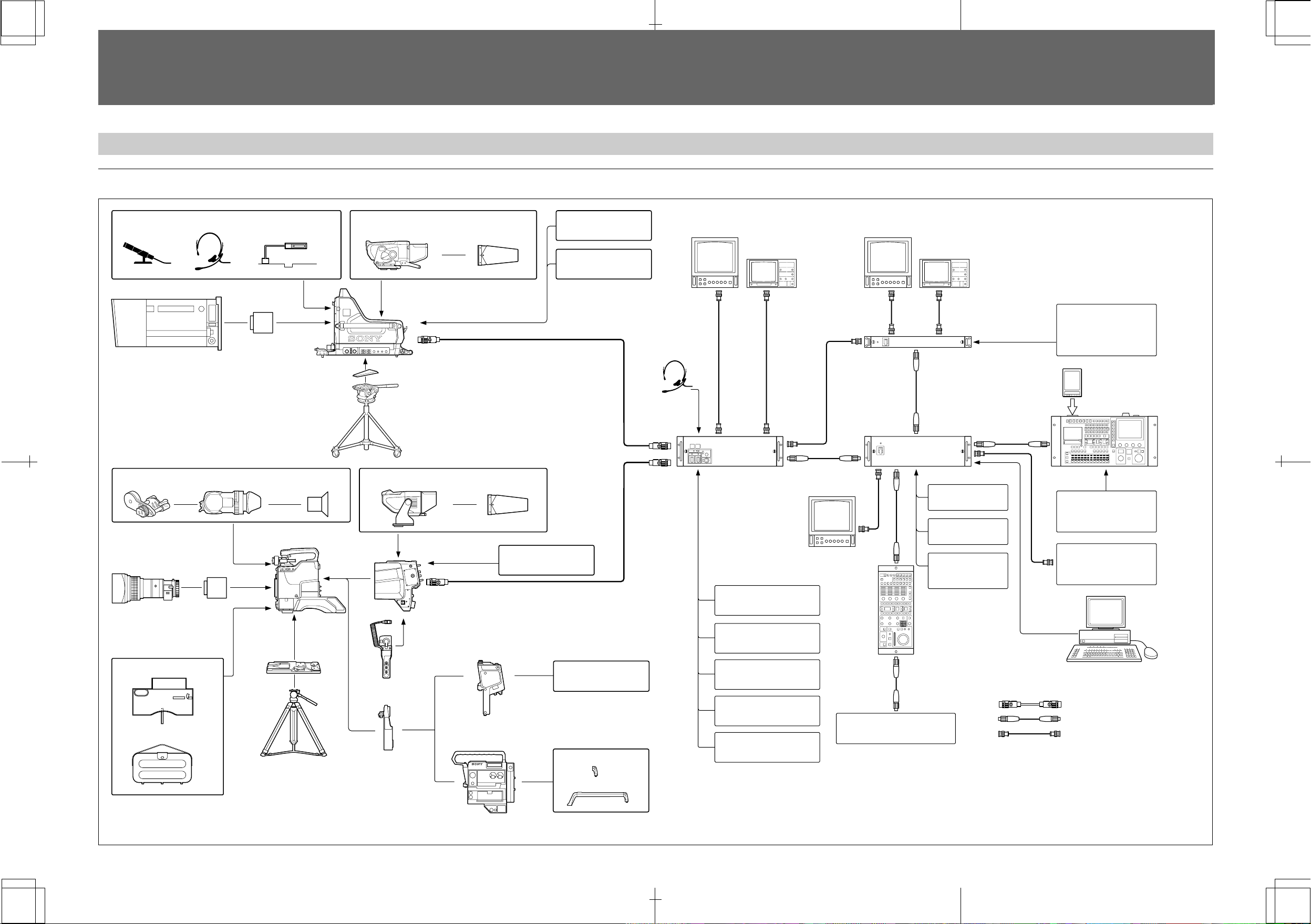
1-2-1 System Configuration
System using the CCU-700A/700AP
Microphone Headset BKP-7911/7912
Script holder
Lens (for studio camera)
OHB-700-series
CCD Unit
BVF-10/10CE/10W/10WCE/
BKW-401
20W/20WCE Viewfinder
BVP-950/950P
Video Camera
Lens (for ENG/EFP)
OHB-700series
CCD unit
VCT-14
Tripod
Adaptor
Water resist cover
Tripod
Carrying case
Eyepiece
BVF-77/77CE/7700/7700P
Viewfinder
BVP-900/900P
a)
Video Camera
V-wedge shoe
Tripod
BVF-55/55CE
Viewfinder
CA-550/550P/570/570P
Camera Adaptor
CAC-6 Return
Video Selector
BVV-5/5P
Videocassette Recorder
CA-553/553P
Camera Adaptor
VFH-770 Hood
VFH-550 Hood
BKP-5971
Teleprompter Kit
CA-3A/3AP
Camera Adaptor
BKP-7010
Long Triax Kit
BKP-7910/7910P
Stand-Alone Kit
b)
Portable VTR
Hook for a shoulder
strap
Long grip
Headset
Picture monitor
Picture monitor
Waveform monitor Waveform monitor
External control
S
equipment
VCS-700
Video Selector
IC card
MSU-700
CNU-700/500
Camera Command
S
1
S
Network Unit
Master Setup Unit
S
CCU-700A/700AP
Camera Control Unit
BKP-7930
c)
CNU IF Board
Switcher
BKP-7900
d)
Extension Board
Character monitor
S
S-BUS Interface
BKP-7933
c)
Routing switcher system
Board
BKP-7310
Long Triax Kit
BKP-7931/7931P
Sub-Encoder Board
RCP-700-series
Remote Control Panel
BKP-7900
Computer (for ISR system)
Extension Board
BKP-7311
SDI Output Board
Iris box
Triax cable
CCA cable
BNC cable
BKP-7312
Return Video Board
a) When the BKP-7090 Upgrade Kit is installed in the BVP-700/700P, the BVP-700/700P has the same function
as the BVP-900/900P. The same function as the BVP-900/900P is also available when the BVP-950/950P and
CA-570/570P is mounted in the CA-905F/905K with the BKP-9057 attached.
b) The BKP-5971 is a kit for the CA-550/550P. The CA-570/570P is provided with the prompter function.
c) The BKP-7930 and BKP-7933 are the boards for the CNU-700.
d) The BKP-7900 is the board for the CNU-700 and CCU-700A/700AP.
Chapter 1 Introduction 1-3
BKP-9901E/3-865-714-02(1)

1-2 Configuration of the BVP-900-series Camera System
System using the CCU-550A/550AP
Microphone Headset BKP-7911/7912
Script holder
Lens (for studio camera)
OHB-700-series
CCD Unit
BVF-10/10CE/10W/10WCE/
BKW-401
20W/20WCE Viewfinder
BVP-950/950P
Video Camera
Lens (for ENG/EFP)
OHB-700series
CCD unit
VCT-14
Tripod
Adaptor
Water resist cover
Tripod
Carrying case
Eyepiece
BVF-77/77CE
Viewfinder
V-wedge shoe
Tripod
BVF-55/55CE
Viewfinder
CA-550/550P/570/570P
Camera Adaptor
CAC-6 Return
Video Selector
CA-553/553P
Camera Adaptor
VFH-770
Hood
BVP-950/950P Video Camera
+CA-570/570P
+CA-905F/905K
+BKP-9057
VFH-550 Hood
BKP-5971
Teleprompter Kit
CA-3A/3AP
Camera Adaptor
BVV-5/5P
Videocassette Recorder
a)
Portable VTR
Hook for a shoulder
strap
Long grip
Headset
Picture monitor
Picture monitor
Waveform monitor Waveform monitor
S
VCS-700
Video Selector
CNU-700/500
Camera Command
S
1
S
Network Unit
S
CCU-550A/550AP
Camera Control Unit
BKP-7930
b)
CNU IF Board
BKP-7900
b)
Extension Board
BKP-5972
Character monitor
S
S-BUS Interface
Board
BKP-7933
b)
Routing switcher system
SDI Output Board
BKP-5973
c)
CCU Control Unit
RCP-700-series
BKP-5974
d)
DC Power Unit
Remote Control Panel
Computer (for ISR system)
Triax cable
Iris box
CCA cable
BNC cable
a) The BKP-5971 is a kit for the CA-550/550P.
The CA-570/570P is provided with the prompter function.
b) The BKP-7900, BKP-7930, and BKP-7933 are the boards for the CNU-700.
c) The BKP-5973 does not function when the CNU-700/500 is connected.
d) The CA-905F/905K cannot be connected to the CCU-550A/550AP with the BKP-5974 installed.
External control
equipment
MSU-700A/750
Master Setup Unit
IC card
Switcher
1-4 Chapter 1 Introduction
BKP-9901E/3-865-714-02(1)
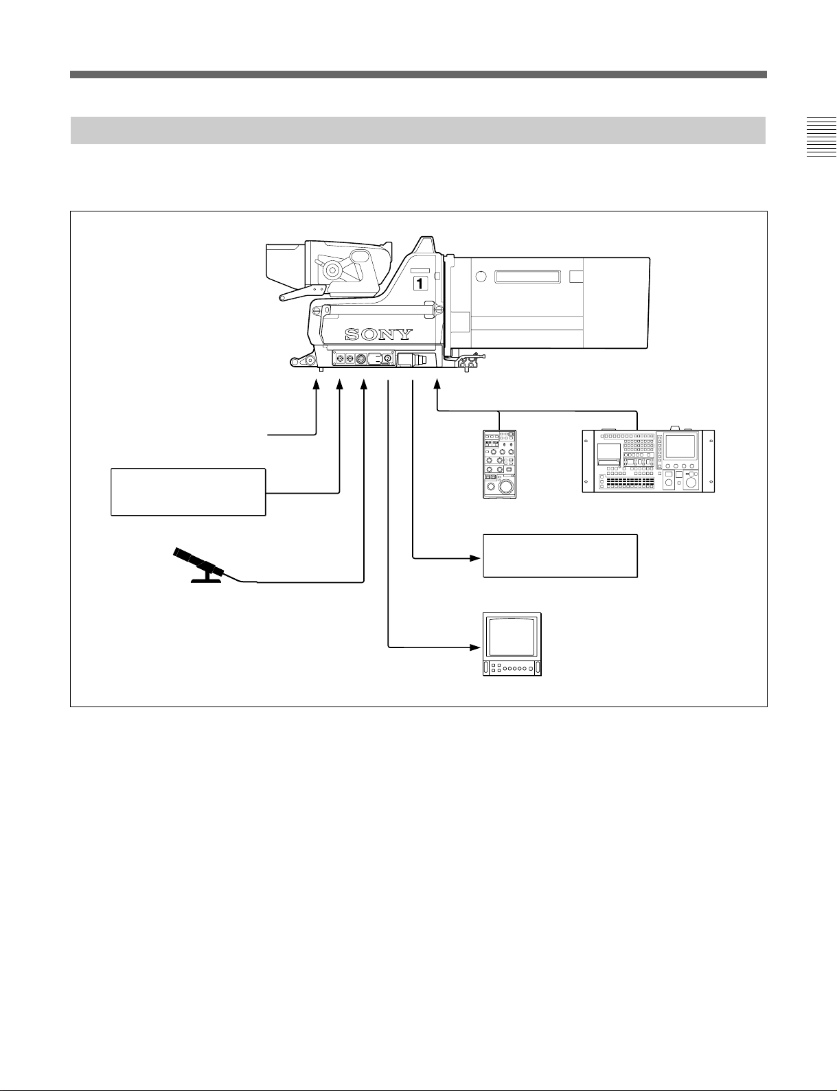
1-2-2 Example When a BVP-900/900P Is Used as a Stand-Alone Camera
A BKP-7910/7910P Stand-Alone Kit should be
installed in the BVP-900/900P.
BVP-900/900P
Reference signal
AC-550
AC power adaptor
Chapter 1
DC IN
AC OUT
VTRVBSREF IN
10.5V-17V
200VA MAX
S
RCP-700-series
S
a)
MSU-700A/750
a)
or RM-B150
Portable VTR
Microphone
a) When the MSU-700A/750 or RCP-700-series unit
is connected to the REMOTE connector, the
functions of the MSU-700A/750 and RCP-700series unit are limited.
Video monitor
Chapter 1 Introduction 1-5

Chapter 1
1-2 Configuration of the BVP-900-series Camera System
1-2-3 Example When a BVP-950/950P Is Used as a Stand-Alone Camera
BVP-950/950P+
CA-530/550/550P/570/570P
VF
S
Power HAD 1000
TEST OUT RET14LOCK REMOTE
MIC1
Reference signal
AC-500/550
AC power adaptor
Microphone
a) When the MSU-700A/750 or RCP-700-series
unit is connected to the REMOTE connector, the
functions of the MSU-700A/750 and RCP-700series unit are limited.
S
RCP-700-series
or RM-B150
Portable VTR
Video monitor
S
a)
MSU-700A/750
a)
1-6 Chapter 1 Introduction
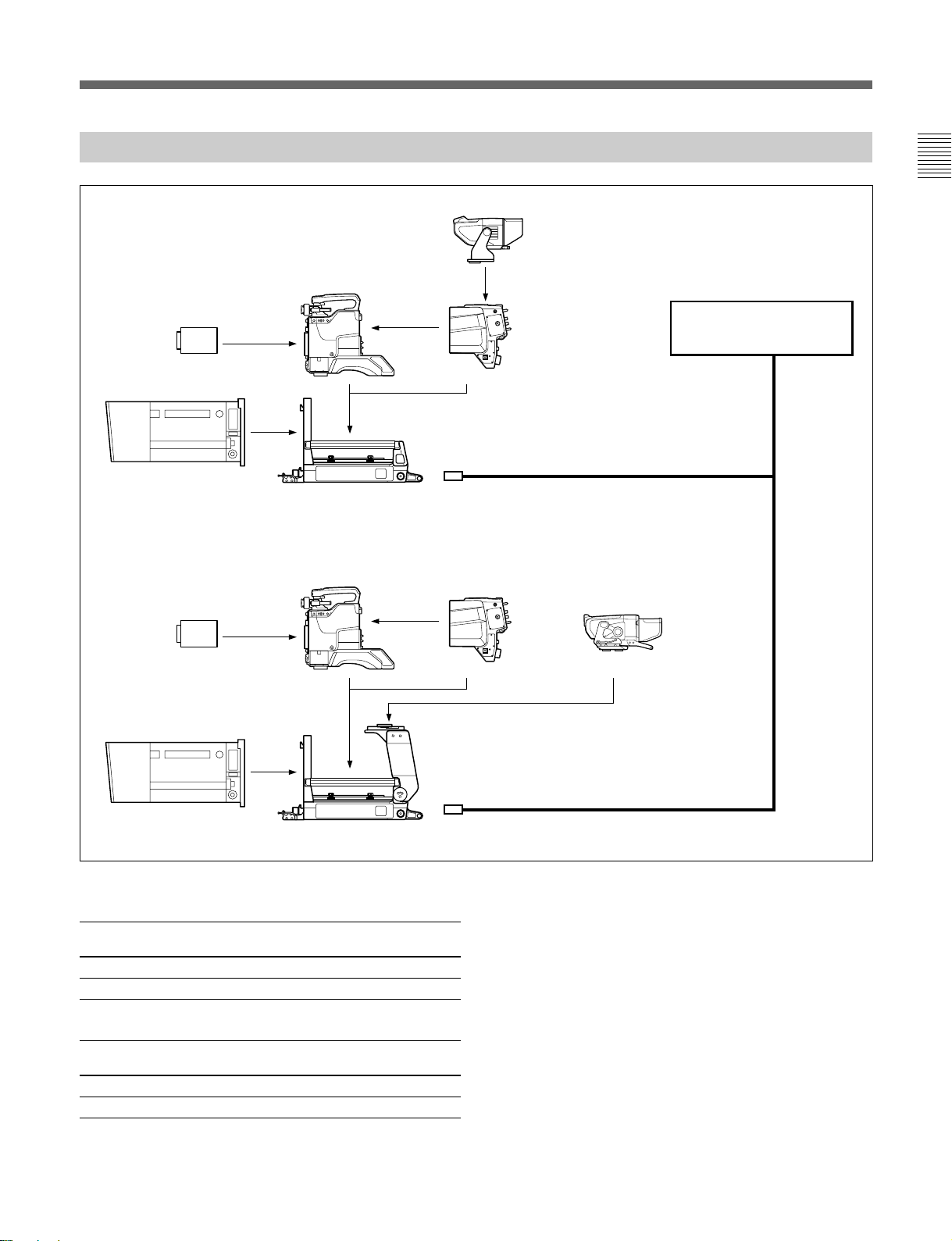
1-2-4 Example When a BVP-950/950P Installed in a CA-905F/905K Is Used
BVF-55/55CE
BVP-950/950P
Chapter 1
CCD unit
Lens for studio use
CCD unit
Lens for studio use
CA-905F/905K
BVP-950/950P
CA-570/570P
CA-570/570P
CCU-550A/550AP/
700A/700AP
Triax cable
BVF-77/77CE/
7700/7700P
CA-905F/905K+BKP-9057
TRIAX cable length
CCU-700A/700AP:
Diameter Maximum Maximum distance for
length prompter signal transmission
8.5 mm 1000 m 500 m
14.5 mm 2000 m 1000 m
CCU-550A/550AP:
Diameter Maximum Maximum distance for
length prompter signal transmission
8.5 mm 700 m 500 m
14.5 mm 1400 m 1000 m
Triax cable
Chapter 1 Introduction 1-7

Chapter 1
1-2 Configuration of the BVP-900-series Camera System
Camera control unit that can be connected
The CCU-550A/550AP and CCU-700A/700AP can be
connected under the following limitations:
• When the BKP-5974 DC power unit has been
installed in the CCU-550A/550AP, the CA-905F/
905K cannot be used.
• When you connect the BVF-7700/7700P to the unit,
the CCU-550A/500AP cannot be used. Use the
CCU-700A/700AP.
• When the CA-570/570P is connected to the CCU550A/550AP, only one channel can be used for
intercom transmission. Use the INCOM1 connector
on the CA-570/570P.
Note
The CCU-550/550P cannot be used with the CA-905F/
905K.
Setting of the intercom microphone switch
When you use the intercom microphone switch located
on the zoom demand of the studio zoom lens, be sure
to set the intercom microphone switch of the CA-570/
570P to OFF (center position).
Check of ROM Version
When connecting the camera, be sure to check the
version of ROM on the AT-121 board corresponding
to the camera to be connected.
If ROM version differ from the below table, be sure to
perform ROM replacement.
Ref. No. ROM version
IC8 Ver.1.22 or higher
IC9 Ver.1.22 or higher
1-8 Chapter 1 Introduction
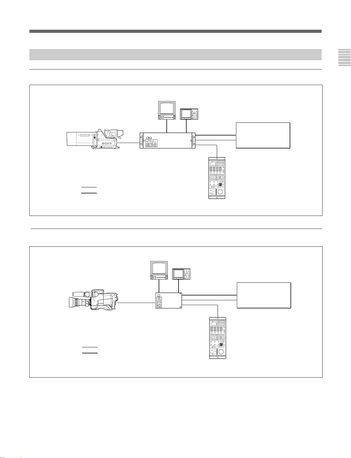
1-2-5 Camera System Using a Camera Control Unit
System using the CCU-700A/700AP
Chapter 1
Picture monitor
BVP-900-series video camera
CCU-700A/700AP
Control signal
Video signal
System using the CCU-550A/550AP
Picture monitor
Waveform monitor
S
1
S
VTR, control
console, etc.
RCP-700-series
Waveform monitor
BVP-950/950P+CA-550/550P/570/570P or
BVP-950/950P+CA-550/550P/570/570P+
CA-905F/905K+BKP-9057
BLK
Control signal
Video signal
S
1
CCU-550A/550AP
VTR, control
console, etc.
S
RCP-700-series
or RM-B150
Chapter 1 Introduction 1-9
Chapter 1
1-2 Configuration of the BVP-900-series Camera System
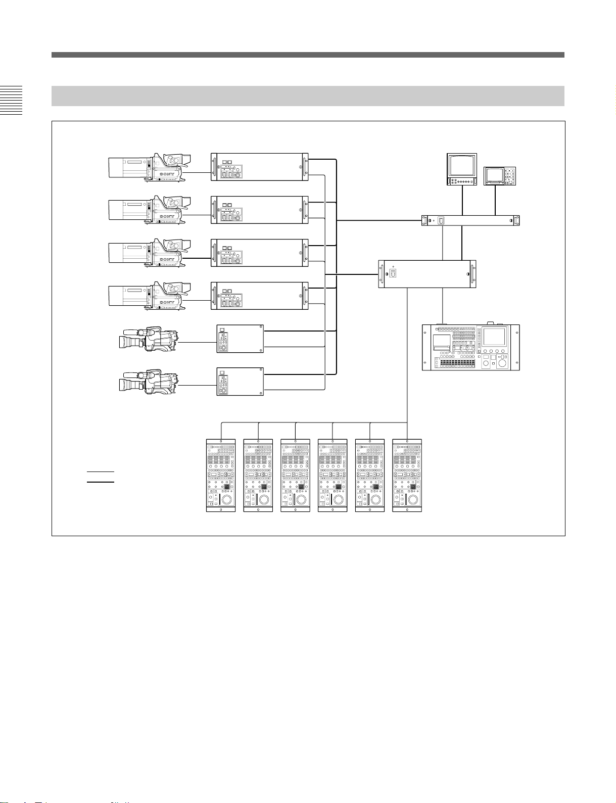
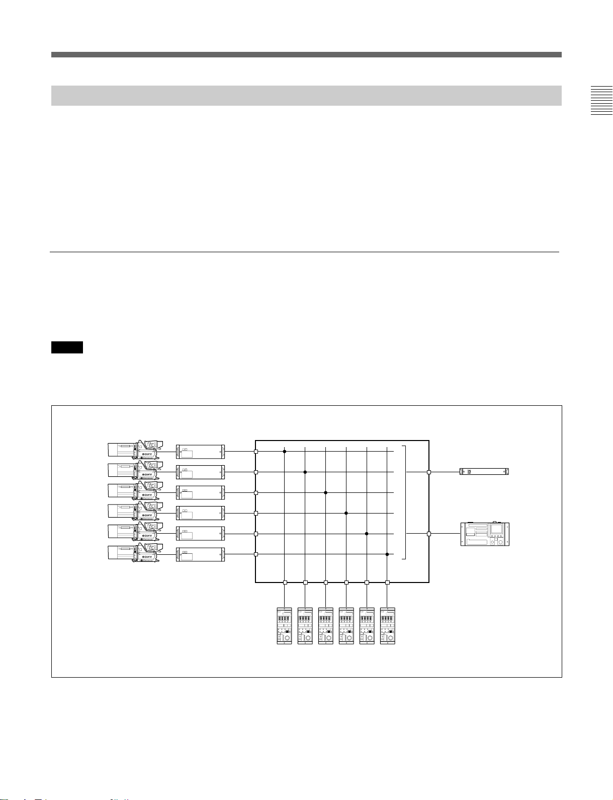
1-2-6 System To Control up to Six BVP-900-series Cameras
BVP-900-series video camera
1
2
3
4
5
6
CCU-700A/700AP/550A/550AP
S
1
S
1
S
1
S
1
S
1
S
1
CNU-700/500
S
Picture monitor
VCS-700
S
S
Waveform monitor
MSU-700A/750
Control signal
Video signal
SSSSSS
RCP-700-series unit
System to control up to six BVP-900-series cameras
1-10 Chapter 1 Introduction
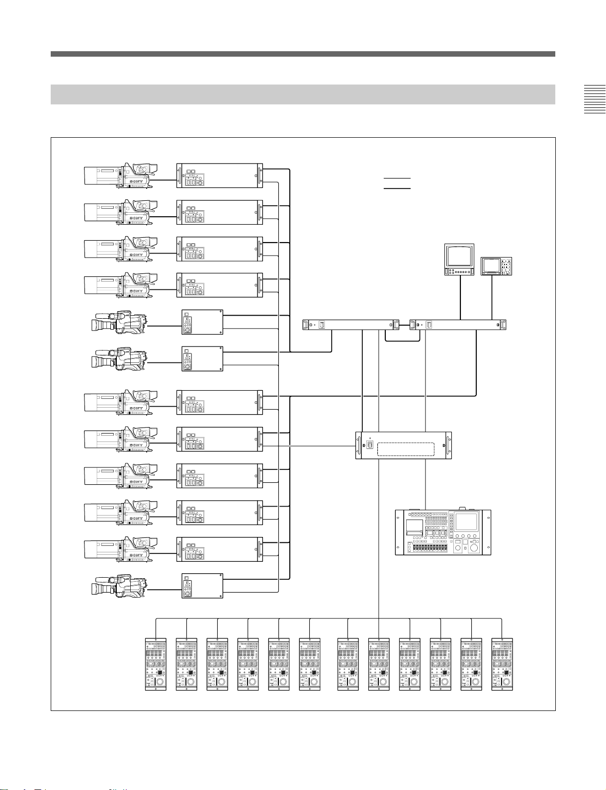
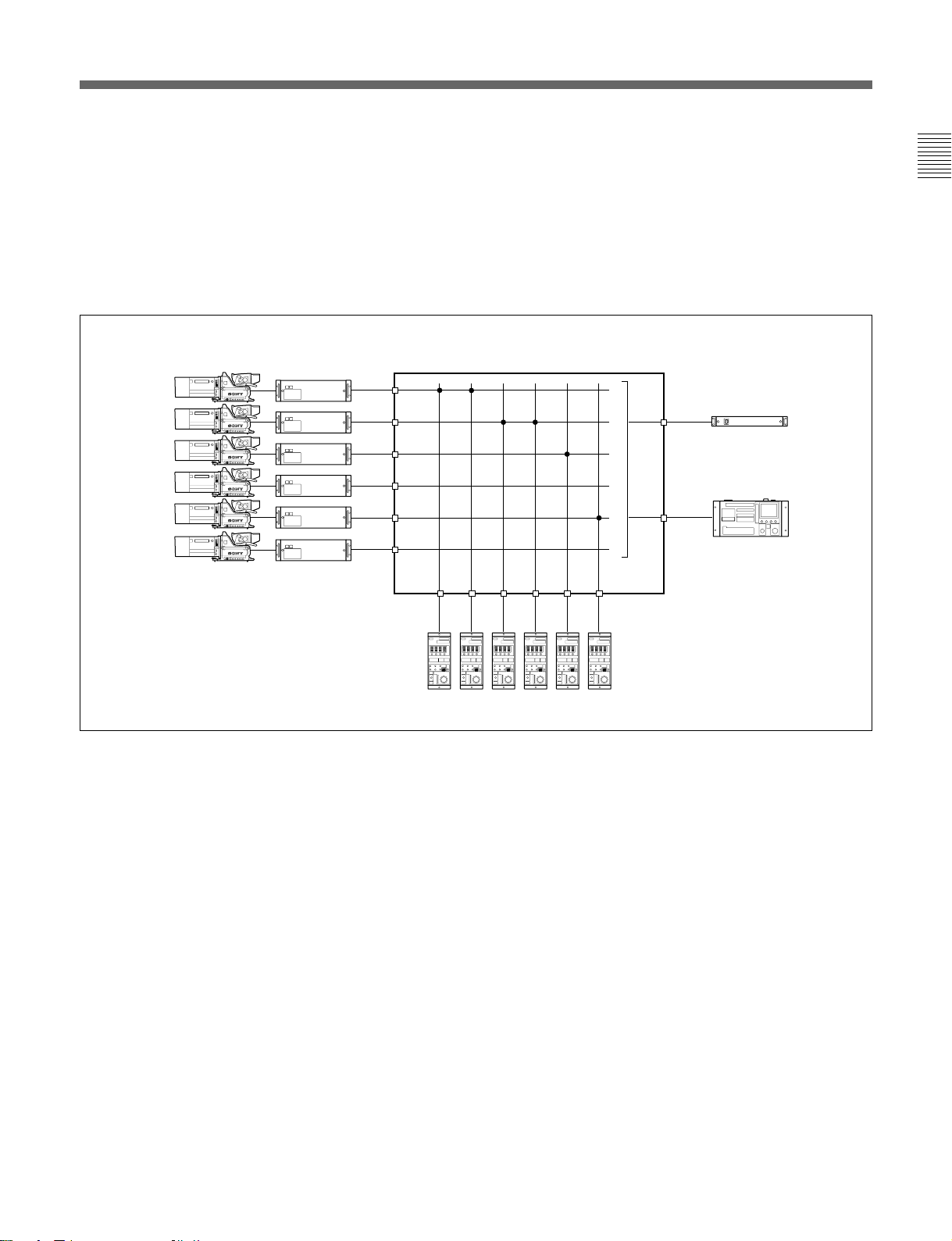
1-2-7 System To Control up to 12 BVP-900-series Cameras Using the CNU-700
Install the BKP-7930 CNU IF board to the CNU-700.
BVP-900-series video camera
1
2
3
4
5
6
7
CCU-700A/700AP/550A/550AP
S
1
S
1
S
1
S
1
S
1
S
1
S
1
Control signal
Video signal
Picture monitor
VCS-700 1 VCS-700 2
S
S
Chapter 1
Waveform monitor
8
9
0
!¡
!™
RCP-700-series unit
S
1
S
CNU-700
BKP-7930
S
1
S
1
S
1
S
1
SSSSSSSSSSSS
S
MSU-700A/750
System to control up to twelve BVP-900-series cameras using the CNU-700
Chapter 1 Introduction 1-11
1-2 Configuration of the BVP-900-series Camera System
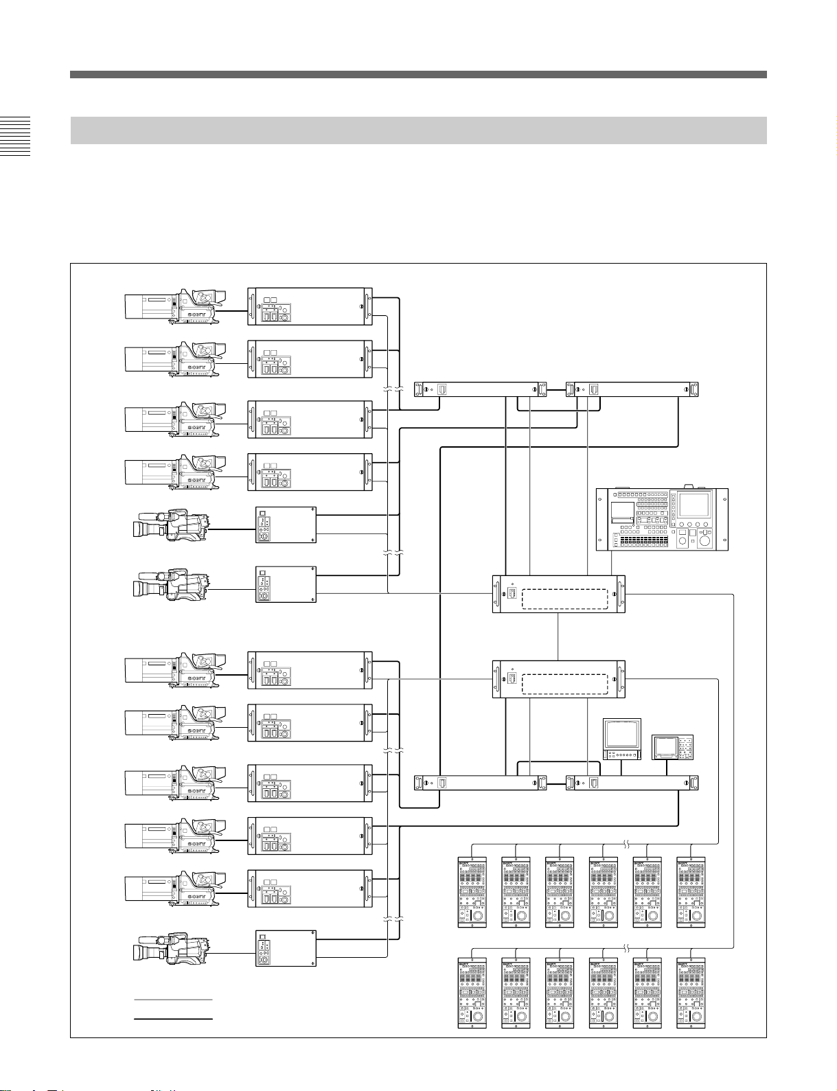
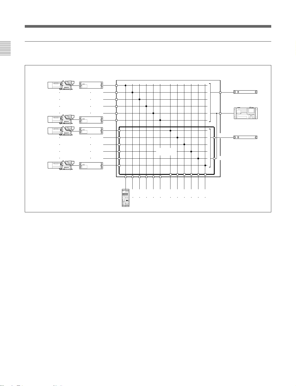
1-2-8 System To Control up to 24 BVP-900-series Cameras Using the CNU-700
Chapter 1
• Up to 24 BVP-900-series video cameras can be
controlled using the two CNU-700s with the BKP7930 installed.
• To use two CNU-700 units, group number setting is
required.
BVP-900-series video camera
1
2
.
.
.
6
7
8
.
.
.
!™
CCU-700A/700AP/550A/550AP
S
1
S
1
S
1
S
1
S
1
S
1
For details, see “3-2-5 Setting the Camera Number and
Group Number.”
• If you wish to create a system using more than 25
cameras and remote control panels, consult your
Sony service representative.
VCS-700 1 VCS-700 2
S S
S
S
BKP-7930
MSU-700A/750
CNU-700
!£
!¢
.
.
.
!•
!ª
@º
.
.
.
@¢
Control signal
Video signal
1-12 Chapter 1 Introduction
S
1
S
BKP-7930
S
1
S
1
S S
VCS-700 3 VCS-700 4
S
1
S
1
S
1
RCP-700-series unit
System to control up to 24 BVP-900-series cameras using the CNU-700
CNU-700
Picture monitor
Waveform
monitor
1-2-9 Control System of the CNU-700/500
The CNU-700/500 Camera Command Network Unit
switches the commands sent from multiple
RCP-700-series Remote Control Panels or the MSU700A/750 Master Setup Unit and sends them to
multiple BVP-900-series Video Cameras. With the
factory settings, the commands are transmitted from
the RCP-700-series unit to the BVP-900-series
cameras connected to the same numbered connectors
series unit connected to the RCP 1 connector sends the
commands to the BVP-900-series camera through the
CCU-700A/700AP connected to the CCU 1 connector.
You can change the combination of the RCP-700series units and BVP-900-series cameras on the CNU700 using the MSU-700A/750. Several examples of
switching of commands by the CNU-700 are
introduced here.
on the CNU-700/500. For example, the RCP-700-
Example of the combination of six video cameras and six remote control panels
The combination of the video cameras and remote
control panels can be changed with the switch on the
AT board of the CNU-700 or with the MSU-700A/
750.
Note
When the CNU-500 is used, the combination of the
RCP-700-series units and BVP-900-series camera
cannot be changed.
Factory setting
Control unit Controlled unit
RCP-1 ——— CCU-1 (for Camera 1)
RCP-2 ——— CCU-2 (for Camera 2)
RCP-3 ——— CCU-3 (for Camera 3)
RCP-4 ——— CCU-4 (for Camera 4)
RCP-5 ——— CCU-5 (for Camera 5)
RCP-6 ——— CCU-6 (for Camera 6)
Chapter 1
BVP-900-series
video camera
1
2
3
4
5
6
CCU-700A/700AP/
550A/550AP
CCU1
CCU2
CCU3
CCU4
CCU5
CCU6
RCP-700-series units
CNU-700/500
RCP1
Factory setting
RCP2
RCP3
RCP4
RCP5
VCS-700
VCS1
MSU-700A/750
MSU1
RCP6
On the display of the RCP-700-series
unit, the camera number controlled
with the unit is displayed.
Chapter 1 Introduction 1-13

Chapter 1
1-2 Configuration of the BVP-900-series Camera System
Modification example 1
Control unit Controlled unit
RCP-1 ——— CCU-6 (for Camera 6)
RCP-2 ——— CCU-5 (for Camera 5)
RCP-3 ——— CCU-4 (for Camera 4)
RCP-4 ——— CCU-3 (for Camera 3)
RCP-5 ——— CCU-2 (for Camera 2)
RCP-6 ——— CCU-1 (for Camera 1)
BVP-900-series
video camera
1
2
3
4
5
6
CCU-700A/700AP/
550A/550AP
CCU1
CCU2
CCU3
CCU4
CCU5
CCU6
RCP-700-series units
CNU-700
RCP1
RCP2
Modification example 1
RCP3
RCP4
RCP5
VCS-700
VCS1
MSU-700A/750
MSU1
RCP6
On the display of the RCP-700-series
unit, the camera number controlled
with the unit is displayed.
1-14 Chapter 1 Introduction
Modification example 2
Control unit Controlled unit
RCP-1 ——— CCU-1 (for Camera 1)
RCP-2 ——— CCU-1 (for Camera 1)
RCP-3 ——— CCU-2 (for Camera 2)
RCP-4 ——— CCU-2 (for Camera 2)
RCP-5 ——— CCU-3 (for Camera 3)
RCP-6 ——— CCU-5 (for Camera 5)
Chapter 1
BVP-900-series
videocamera
1
2
3
4
5
6
CCU-700A/700AP/
550A/550AP
CCU1
CCU2
CCU3
CCU4
CCU5
CCU6
RCP-700-series units
CNU-700
RCP1
RCP2
Modification example 2
RCP3
RCP4
RCP5
VCS-700
VCS1
MSU-700A/750
MSU1
RCP6
On the display of the RCP-700-series
unit, the camera number controlled
with the unit is displayed.
Chapter 1 Introduction 1-15
1-2 Configuration of the BVP-900-series Camera System
Example of the combination of 12 video cameras and 12 remote control panels
Chapter 1
Install the BKP-7930 to the CNU-700.
BVP-900-series
video camera
1
2
3
4
5
6
7
8
9
0
!¡
!™
CCU-700A/700AP/
550A/550AP
RCP-700-series units
CNU-700+BKP-7930
CCU1
CCU2
CCU3
CCU4
CCU5
CCU6
CCU7
CCU8
CCU9
CCU10
CCU11
CCU12
RCP1
RCP2
RCP3
RCP4
BKP-7930
RCP5
RCP6
RCP7
RCP8
RCP9
RCP10
RCP11
VCS-700 1
VCS1
MSU-700A/750
MSU1
VCS2
MSU2
RCP12
On the display of the RCP-700series unit, the camera number
controlled with the unit is
displayed.
VCS-700 2
Example of the combination of 12 video cameras and 12 remote control panels
1-16 Chapter 1 Introduction
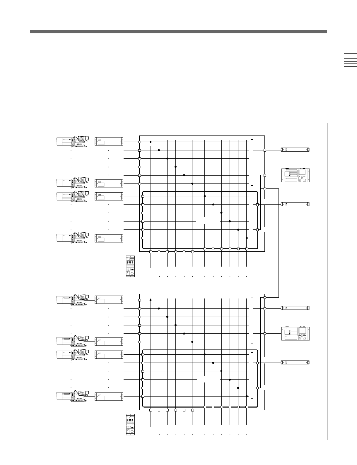
Example of a combination of 24 video cameras and 24 remote control panels
• Two CNU-700s with the BKP-7930 installed are
used.
• The MSU-700A/750 can assign the combination of
the video cameras and remote control panels that are
connected to the CNU-700 to which the MSU-700A/
750 is connected directly. (For example in the figure
below, the MSU-700A/750 connected to the upper
BVP-900-series
video camera
1
2
3
4
5
6
7
8
9
0
!¡
!™
CCU-700A/700AP/
550A/550AP
CCU1
CCU2
CCU3
CCU4
CCU5
CCU6
CCU7
CCU8
CCU9
CCU10
CCU11
CCU12
CNU-700+BKP-7930
CNU-700 can change the combination of the video
cameras 1 to !™ and the remote control units
connected to the upper CNU-700.)
• If you wish to create a system using more than 25
cameras and remote control panels, consult your
Sony service representative.
VCS-700 1
VCS1
MSU-700A/750
MSU1
AUX1
VCS-700 2
VCS2
BKP-7930
MSU2
Chapter 1
BVP-900-series
video camera
!£
!¢
!∞
!§
!¶
!•
!ª
@º
@¡
@™
@£
@¢
RCP-700-series units
CCU-700A/700AP/
550/550P
RCP-700-series units
CNU-700+BKP-7930
CCU1
CCU2
CCU3
CCU4
CCU5
CCU6
CCU7
CCU8
CCU9
CCU10
CCU11
CCU12
RCP1
RCP1
RCP2
RCP2
RCP3
RCP3
RCP4
RCP4
RCP5
RCP5
RCP6
BKP-7930
RCP6
RCP7
RCP7
RCP8
RCP8
RCP9
RCP9
RCP10
RCP11
RCP10
RCP11
RCP12
AUX1
VCS-700 3
VCS1
MSU-700A/750
MSU1
VCS-700 4
VCS2
MSU2
On the display of the RCP-700series unit, the camera number
RCP12
controlled with the unit is
displayed.
Example of the combination of 24 video cameras and 24 remote control panels
Chapter 1 Introduction 1-17
1-2 Configuration of the BVP-900-series Camera System
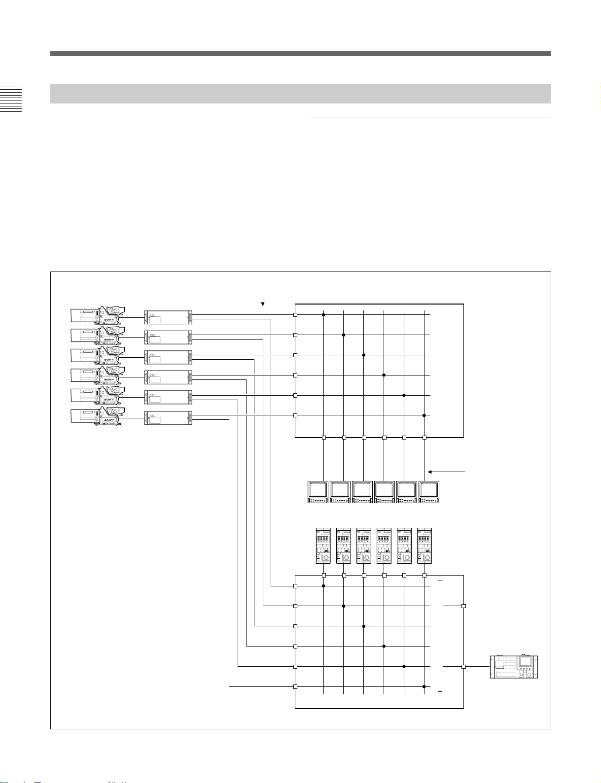
1-2-10 S-BUS Control System Using the CNU-700
Chapter 1
When a BKP-7933 S-BUS Interface Board is installed
in the CNU-700, the routing switcher system can
control the BVP-900-series camera system via the SBUS.
For details on installation and settings, refer to the
Installation Manual furnished with the BKP-7933.
Source
number
SERIAL
OUT
SERIAL
OUT
SERIAL
OUT
SERIAL
OUT
SERIAL
OUT
SERIAL
OUT
(001)
(002)
(003)
(004)
(005)
(006)
1
2
3
4
5
6
CCU1
CCU2
CCU3
CCU4
CCU5
CCU6
Switching the pictures sent to the picture
monitors linked with RCP assignment
When the MSU-700A/750 assigns an RCP, the camera
that is controlled with the assigned RCP-700-series
unit is changed, and the picture sent to each picture
monitor is also changed to the picture from the camera.
For example, the camera controlled with RCP-1 is
changed from CAM1 to CAM5, so the picture sent to
the picture monitor for RCP1 is changed from CAM1
to CAM5.
Digital video routing switcher
IN1
IN2
IN3
IN4
IN5
IN6
BVP-900-series
video camera
CCU-700A/700AP/
550A/550AP
RCP1 RCP2 RCP3 RCP4 RCP5 RCP6
CCU1
CCU2
CCU3
CCU4
CCU5
CCU6
CNU-700+BKP-7933
OUT1
(001)
OUT2
(002)
OUT3
(003)
OUT4
(004)
OUT5
(005)
OUT6
(006)
RCP-700-series units
Destination
number
Picture monitors
MSU1
MSU-700A/750
1-18 Chapter 1 Introduction
Switching the pictures sent to the picture monitors linked with RCP assignment
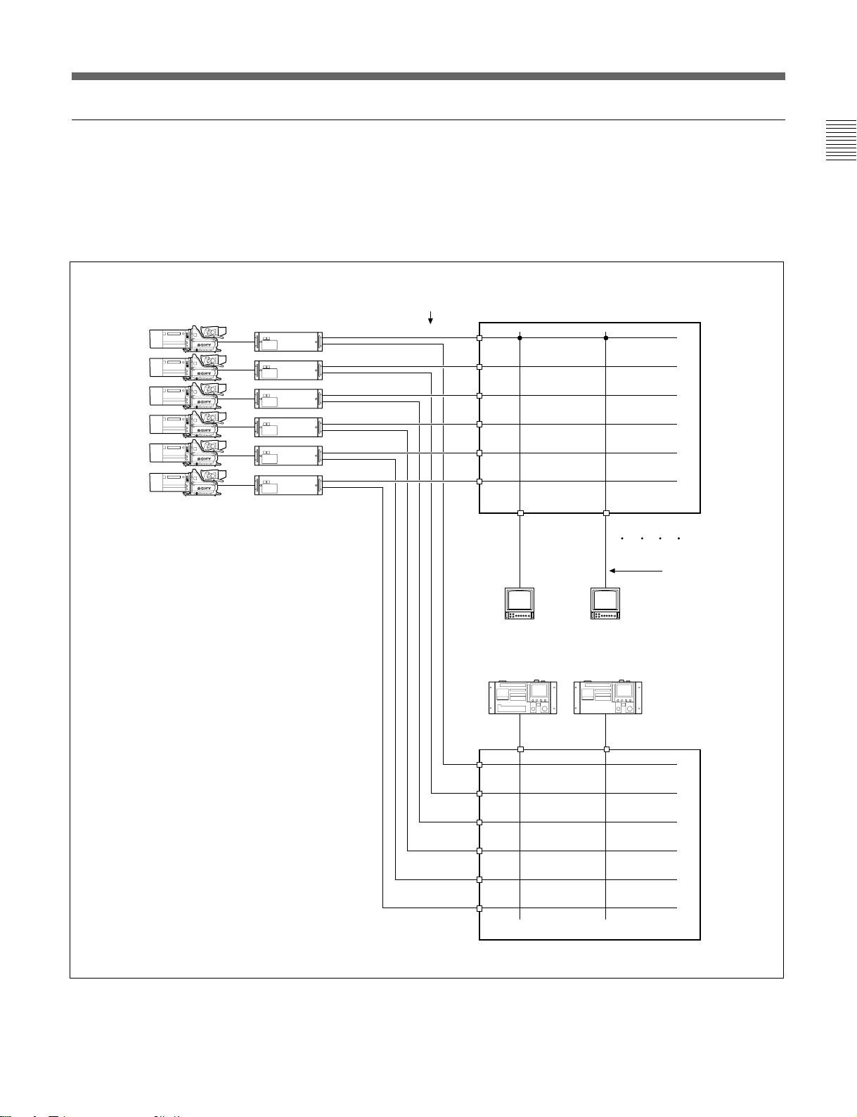
Switching the pictures sent to the picture monitors linked with the camera selection on
the MSU-700A/750
When a camera select button on the MSU-700A/750 is
pressed, the picture from the selected camera appears
on the corresponding picture monitor. This function is
convenient for switching SDI signals.
Source
1
2
3
4
5
6
CCU1
CCU2
CCU3
CCU4
CCU5
CCU6
SERIAL
OUT
SERIAL
OUT
SERIAL
OUT
SERIAL
OUT
SERIAL
OUT
SERIAL
OUT
number
(001)
(002)
(003)
(004)
(005)
(006)
Digital video routing switcher
IN1
IN2
IN3
IN4
IN5
IN6
Chapter 1
BVP-900-series
video camera
CCU-700A/700AP/
550A/550AP
CCU1
CCU2
CCU3
CCU4
CCU5
CCU6
OUT13
(0013)
MSU1 MSU2
MSU1
OUT14
(0014)
MSU2
Destination
number
Picture monitor
MSU-700A/750
CNU-700+BKP-7930+BKP-7933
Switching the picture on the picture monitor linked with the camera selection on the MSU-700A/750
Chapter 1 Introduction 1-19
 Loading...