

Sony BVP-900, BVP-900P, BVP-900WSPK Operation Manual

COLOR VIDEO CAMERA
BVP-900/900P/
900WSPK
OPERATION MANUAL
1st Edition (Revised 2)
Serial No. 10001 and Higher (UC)
Serial No. 15001 and Higher (UC)
Serial No. 40001 and Higher (CE)
Serial No. 45001 and Higher (CE)
[English/German]

English
WARNING
To prevent fire or shock hazard, do not
expose the unit to rain or moisture.
To avoid electrical shock, do not open the
cabinet. Refer servicing to qualified
personnel only.
For the customers in the USA
This equipment has been tested and found to comply
with the limits for a Class A digital device, pursuant to
Part 15 of the FCC Rules. These limits are designed to
provide reasonable protection against harmful
interference when the equipment is operated in a
commercial environment. This equipment generates,
uses, and can radiate radio frequency energy and, if not
installed and used in accordance with the instruction
manual, may cause harmful interference to radio
communications. Operation of this equipment in a
residential area is likely to cause harmful interference in
which case the user will be required to correct the
interference at his own expense.
You are cautioned that any changes or modifications not
expressly approved in this manual could void your
authority to operate this equipment.
The shielded interface cable recommended in this
manual must be used with this equipment in order to
comply with the limits for a digital device pursuant to
Subpart B of Part 15 of FCC Rules.

Table of Contents
English
Overview.............................................................................................2 (E)
Features........................................................................................... 2 (E)
File System ..................................................................................... 3 (E)
Optional Accessories ...................................................................... 4 (E)
Location and Function of Parts........................................................5 (E)
Side Panels...................................................................................... 5 (E)
Rear Panel....................................................................................... 8 (E)
Setting Up the Camera .................................................................... 14 (E)
Mounting the CCD Unit ............................................................... 14 (E)
Mounting the Camera to the Tripod ............................................. 16 (E)
Attaching the Lens to the Camera ................................................ 17 (E)
Attaching the 7-inch Viewfinder .................................................. 18 (E)
Specifications.................................................................................... 21 (E)
Manuals for the BVP-900-series video camera system
Three types of manuals are provided for the BVP900-series video camera system: an Operation
Manual, a Maintenance Manual, and a System
Manual. The Operation and Maintenance Manuals
are provided for each device used in the system, and
the System Manual is provided as an option.
In the Operation Manual, specific functions and
characteristics of the device, such as features,
functions of each part and specifications, are
described.
In the Maintenance and System Manuals, you will
find general information on the system, such as
possible system configurations, the setup method,
connections, and system preparations and
operations.
1 (E)

Overview
The BVP-900/900P Color Video Camera is a camera
head designed for a Sony CCD camera system used in
a studio and outside broadcast applications. The BVP900-series video camera system is composed of
independent units each of which has its unique
function like a pickup device, camera head, camera
control unit, video selector, master setup unit, remote
control panel, etc. So a wide variety of systems are
available for your special purposes.
Thanks to a newly developed CNU-700 Camera
Command Network Unit, a system can control up to 96
video cameras.
Features
Easily changeable CCD unit
The CCD unit is designed as a separate block from the
camera head so you can easily change the aspect ratio
(4:3 or 16:9) simply by replacing the unit. No
readjustment is required after the change under normal
operating conditions.
Easy-to-operate design
The new body design lowers the viewfinder position,
which decreases the parallax of the lens and
viewfinder. Also, the angle of view from the camera
operator's position is wider, as the total height of the
camera is lower than with the conventional unit.
High vertical resolution: The vertical resolution can
be improved to 450 lines for the BVP-900 or to 550
lines for the BVP-900P using the EVS (Enhanced
Vertical Definition System) function. The super
EVS function enables you to adjust vertical
resolution to the desired value between 350 and 450
lines for the BVP-900 (only with the OHB-750A/
750WSA CCD Unit) or between 450 and 550 lines
for the BVP-900P (only with the OHB-750AP/
750WSAP CCD Unit).
Automatic setup and filing function
Built-in microcomputers actualize quick and precise
automatic setup, and also reduce the time required for
maintenance. The adjusted data can be stored in the
camera with a filing system.
Electronic shutter
An electronic shutter of 6 speeds (from
to 1/2000) is provided with the BVP-900/900P. You can
shoot a rapidly moving object clearly by selecting the
optimal shutter speed. It also has an ECS (Extended
Clear Scan) function. Using this function, you can
adjust the shutter speed of the BVP-900 in 510 steps
1
(from
BVP-900P in 607 steps (from
to 1/9000). Appropriate shutter-speed selection using the
ECS function enables minimizing horizontal streaks
when shooting a computer display screen.
/30 to 1/58.3 and from 1/60 to 1/7000), and that of the
1
/25 to 1/48.7 and from 1/50
1
/100
High quality
High picture quality: A newly developed video-
processing LSI for broadcasting cameras assures a
high-quality picture required for a studio-use CCD
camera.
High signal-to-noise ratio: A high signal-to-noise
ratio has been achieved as a result of the use of a
top-performing CCD, a new video-processing LSI
and a 12-bit A/D converter.
Wide dynamic range: Automatic and manual control
capabilities for knee point and knee slope enables
reproducing high-luminance subjects clearly in up
to 600% normal light.
High sensitivity: A sensitivity of F8 at 2,000 lux
(typical) has been achieved. When the video gain
is raised by 18 dB, a video level of 100% is
obtained with minimum subject illuminance of 7.5
lux.
Dynamic shading compensation function
When you change the zoom position with the aperture
almost completely open, the modulation shading will
appear. The BVP-900/900P can automatically
compensate for such phenomena to obtain optimum
picture quality at any zoom position. (This function is
activated only when a lens allowing this function is
attached.)
Variety of audio capabilities
The BVP-900/900P has two microphone channels, two
intercom channels, and one program audio channel.
You can set the microphone channel to line level (0
dBu) with the switch on the side panel, and monitor
the microphone or line channel with the intercom
headset. The two intercom channels can be connected
to either the producer line or engineer line by setting
the corresponding switches on the rear panel.
Self-diagnostics functions
The BVP-900/900P has self-diagnostics functions to
facilitate troubleshooting.
2 (E)

Display capability
The BVP-900/900P displays the zoom position, focus
position, the setting status of a camera and warning
messages on the viewfinder screen in characters
generated by a built-in character generator. A box
cursor, center marker, safety zone, and zoom position
are also displayed on the viewfinder screen.
High-resolution 7-inch viewfinder attachable
An optional 7-inch BVF-77/77CE black-and-white
viewfinder or 7-inch BVF-7700/7700P color
viewfinder can be used with the BVP-900/900P.
For easy-to-see operation, the viewfinder angle can
easily be changed and fixed in the desired position.
You can attach and detach the viewfinder without any
tools.
Picture-in-picture capability
You can simultaneously check the camera picture and
the return video picture.
High-picture-quality return video
Monitoring a high-quality return video picture on a
black-and-white viewfinder or color viewfinder is
possible thanks to a 3-line-adapted comb filter.
Reliable transmission using a triax cable
The BVP-900/900P supplies wideband component
video signals (Y, R–Y, and B–Y) to a CCU-700A/
700AP via a triax cable of high transmission
reliability. A triax cable simultaneously transmits
power, video, audio, and control signals between the
BVP-900/900P and CCU-700A/700AP. Higher
resolution and picture quality have been achieved
thanks to its wide bandwidth.
File System
The BVP-900/900P has the capability of storing the
adjustment data in one of the following files.
Reference file
The reference file stores the reference values used for
automatic setup adjustment and the standard settings of
the switches.
Scene files
Scene files store paint data for each scene. For
example, if you store data prepared in rehearsal for a
particular scene in a scene file, the data can be
retrieved to reproduce the same camera settings as
used in rehearsal.
Lens files
Lens files store specific data for a lens to be used.
When you use a recommended lens, the standard
values are stored in a lens file at the factory.
OHB files (stored in the CCD unit)
OHB files store specific data for a CCD unit to be
used. The standard values are stored in an OHB file at
the factory.
Creation, storage and retrieval of files are performed
using an optional MSU-700 Master Setup Unit or
RCP-700-series Remote Control Panel. The type and
number of files which can be handled depend on the
used unit.
For details, refer to the System Manual.
Compact, lightweight, and power-saving
design
The BVP-900/900P has a compact, lightweight, and
low-power consumption design, which are basic
requirement for outdoor broadcasting.
3 (E)
Overview
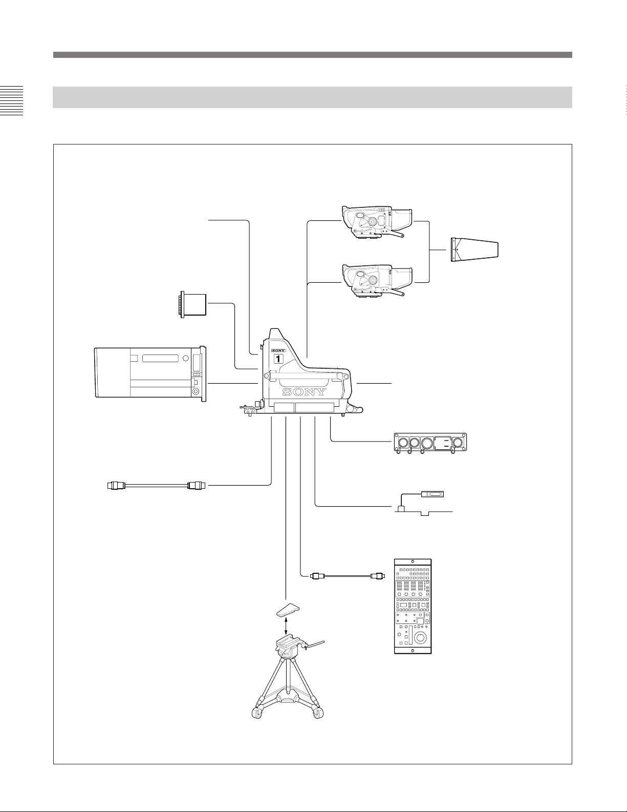
Optional Accessories
The following optional accessories are available.
7-inch viewfinder
Front cover (supplied)
OHB-750A/750WSA/730/730WS/
750AP/750WSAP/730P/730WSP
CCD Unit
Zoom lens
Triax cable
VFH-770 7-inch Viewfinder
Sports Hood
BVF-7700/7700P
(with standard hood)
BVF-77/77CE
(with standard hood)
BVP-900/900P
Color Video Camera
BKP-7010 Long Triax Kit
BKP-7910/7910P Stand-Alone Kit
(for using the BVP-900/900P as a
stand-alone unit)
4 (E)
BKP-7911/7912 Script Holder
(a script light included)
S
CCA-5 cable
V-wedge shoe
(supplied with the tripod)
RCP-700-series
Remote Control Panel
or
RM-B150
Remote Control Unit
Tripod
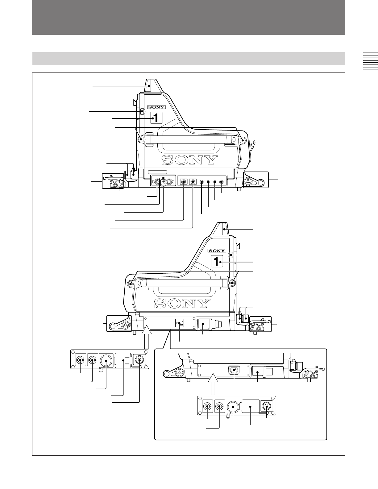
Location and Function of Parts
Side Panels
1Up tally lamp
2Safety lock
3Camera number plate
4Side-panel lock screws
5Lens lock and knob
Power HAD 1000
AUDIO IN
6Cable clamp
7AUDIO IN CH-1 and CH-2 connectors
8AUDIO IN selector
9Microphone power switches
!ºPROMPTER connector
!¡TEST OUT connector
CH-1 CH-2
MIC
LINE
1
2
+48V
OFF
TEST OUTPROMPTER TRACKER RET
CONTROL
SCRIPT
!¢SCRIPT connector
!£RET CONTROL connector
!™TRACKER connector
REMOTE
!∞REMOTE connector
1Up tally lamp
!§Accessory
bracket
!§Accessory bracket
AC OUT
BKP-7910
Stand-Alone
a)
Kit
VTRVBSREF IN
200VA MAX
!ªREF IN connector
@ºVBS connector
@¡VTR connector
!¶AC OUT connector
@™DC IN connector
a)The BVP-900/900P can be used as a
stand-alone camera by installing an
optional BKP-7910/7910P Stand-Alone Kit.
DC IN
11 .5V-18V
AC OUT
200VA MAX
!•CCU connector
!¶AC OUT connector
BVP-900P
BKP-7910P
Stand-Alone
a)
Kit
!ªREF IN connector
@ºVBS connector
2Safety lock
3Camera number plate
4Side-panel lock screws
5Lens lock and knob
AC OUT
200VA MAX
!•CCU connector
!¶AC OUT connector
VTRVBSREF IN
AC OUT
200VA MAX
DC IN
11.5V-18V
@™DC IN connector
!¶AC OUT connector
@¡VTR connector
6Cable clamp
5 (E)

Location and Function of Parts
1 Up tally lamp
Lights when the camera receives a red tally signal.
When the CALL button on the MSU-700 or
RCP-700-series unit is pressed with the CCU CALL
switch on the internal MS board set to ON, the lamp
lights if it is not lit, and goes out if it is lit. You can
adjust the brightness of the lamp with the control on
the internal MS board.
Not to have this lamp light, set the UP TALLY switch
on the rear panel to OFF.
Attach the supplied number plate (0 through 9) to
show the camera number.
For details on adjusting the brightness and attaching the
number plate, refer to the System Manual.
2 Safety lock
Locks the side panel to prevent it from accidentally
opening. To open the side panel, loosen the side-panel
lock screw, slide the safety lock toward the lens, and
open the panel.
When you close the side panel, it automatically locks.
For details, refer to the System Manual.
8 AUDIO IN (audio input select) selector
Set to the appropriate position according to the
equipment connected to the AUDIO IN CH-1 and
CH-2 connectors.
MIC: When microphones are connected.
LINE: When a line-level signal source is connected.
9 Microphone power switches
For the microphones connected to the AUDIO IN CH1 and CH-2 connectors, respectively.
+48 V: When the connected microphone requires an
external power source.
A power of +48 V is supplied to the microphone.
OFF: When the connected microphone requires no
external power.
: Not used
•
!º PROMPTER (teleprompter) connector
(BNC type)
Supplies the signal for the teleprompter monitor, which
is input to the PROMPTER INPUT connector on the
CCU-700A/700AP.
3 Camera number plate
Attach the supplied light gray number plate to show
the camera number.
For details how to attach a number plate, refer to the
System Manual.
4 Side-panel lock screws
Lock the side panel to prevent it from accidentally
opening. Turn it fully clockwise.
5 Lens lock and knob
Locks the lens. To attach or detach the lens, turn the
knob fully counterclockwise until the lever is
horizontal. To lock the lens, turn the knob clockwise
until the lever is vertical.
6 Cable clamp
Fixes the triax cable. This accepts a cable from 8 to 15
mm in diameter.
For details on how to use the cable clamp, refer to the
System Manual.
7 AUDIO IN CH-1 and CH-2
(audio input channels 1 and 2) connectors (XLR
3-pin)
Accept microphone or line level signals.
!¡ TEST OUT (test signal output) connector (BNC
type)
Supplies the signal selected with the video signal select
buttons on the rear panel when the TEST OUT switch
on the MS board is set to VF.
When the TEST OUT switch is set to RET, a return
video signal is output. (The return video signal
selected last is output.)
When a BKP-7910/7910P Stand-Alone Kit is installed
in the camera, a composite video signal is output if the
TEST OUT switch is set to VBS.
!™ TRACKER connector (10-pin)
Used for communication between the camera operator
and tracker and for intercom 1 and 2 connection. This
also supplies the up tally and program audio signals.
!£ RET CONTROL (return video control)
connector (6-pin)
Used for switching the return video 1, 2, 3, and 4
signals and for turning the intercom microphone on or
off from the external equipment.
!¢ SCRIPT (script light) connector (4-pin)
Supplies power (12 V, 5 W maximum) for the script
light.
6 (E)

!∞ REMOTE connector (8-pin)
Connect an optional master setup unit or remote
control unit/panel using a CCA cable. Then you can
control the camera with these units.
!§ Accessory bracket
Attach an optional accessory, such as a BKP-7911/
7912 Script Holder or focus/zoom demand.
For attaching the accessory, refer to the instruction manual
supplied with the accessory.
!¶ AC OUT (AC power output) connector
Supplies AC power (200 VA maximum).
!• CCU (camera control unit) connector
(triax connector)
Connect to the CAMERA connector on a CCU-700A/
700AP using a triax cable. All of the signals in a
BVP-900-series camera system such as the power,
control, video, and audio signals can be transmitted
between this unit and a CCU-700A/700AP using a
single triax cable.
!ª REF IN (reference signal input) connector
1)
(BNC type)
Accepts a VBS or black burst signal for gen-lock when
using the BVP-900/900P as a stand-alone camera.
@º VBS (video signal output) connector
1)
(BNC type)
Supplies composite video signals when using the BVP900/900P as a stand-alone camera.
1)
@¡ VTR connector
(26-pin)
Connect a VTR using a CCZ or CCZQ cable when
using the BVP-900/900P as a stand-alone camera.
1)
@™ DC IN (DC power input) connector
(4-pin)
Connect a DC power source (11.5 V to 18 V) when
using the BVP-900/900P as a stand-alone camera.
....................................................................................................................................................................................................................................................
1) These connectors are equipped with the BKP-7910/7910P
Stand-Alone Kit.
7 (E)
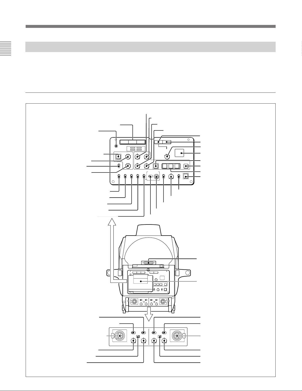
Location and Function of Parts
Rear Panel
The functions of the switches and controls numbered
1 through #º are the same for the BVP-900 and BVP900P. The switches and controls numbered #¡ through
#§ are for the BVP-900, and those numbered #¶
Rear panel of the BVP-900
2Video signal select buttons
1POWER indicator
R G B RET RET 1
POWER
3
@•FILTER LOCAL button
@¶ND filter control
@§Spare switch
@∞CC filter control
@¢CENTER MARKER switch
@£SAFETY ZONE switch
@™UP TALLY switch
@¡MIX VF switch
@ºDISPLAY switch
FILTER LOCAL
CENTER
MARKER
ON
OFF
2
4
1
5
ND
C
D
B
A
E
CC
SAFETY
UP TALLY MIX VF MENU SELECTDISPLAY
ZONE
ON
ON
OFF
OFFONOFF MENU
H-POSI
WIDTH
OFF
through $™ are for the BVP-900P.
For the switches and controls numbered #¶ through $™ for
the BVP-900P, see “Rear panel of the BVP-900P”.
3H-POSI control
4V-POSI control
5WIDTH control
6HEIGHT control
7RET button
8RET 1 button
V-POSI
HEIGHT
ON
CANCEL ENTER
STORE
RETURN
SELECT
3
2
1
1
VF DETAIL
ON
OFF
4
CURSOR
2
1
3
PinP
POSITION
ON
OFF
ON
CALL
9RETURN SELECT knob
!ºBack tally lamp
!¡CURSOR STORE button
!™CURSOR ON button
!£CURSOR 1, 2, and 3 buttons
!¢CALL button
!∞PinP switch
!§VF DETAIL control
!¶VF DETAIL switch
!•MENU SELECT knob
!ªMENU SELECT switch
8 (E)
#¡MIC ON/OFF switch
#™INTERCOM PROD/ENG switch
#£INTERCOM 1 connector
INTERCOM 1 INTERCOM 2
#¢INTERCOM control
#∞REVERSE switch
#§PGM control
MIC MIC
ENG PROG
ENG PROG
ENG PROD
ENG PROG
REVERSE REVERSE
INTERCOM
PGM
INTERCOM 1 INTERCOM 2
ENG PROG
INTERCOM
INTERCOM
MIC MIC
OFF ON
PGM
ENG PROD
INTERCOM
REVERSE REVERSE
@ªVF connector
1
#ºMemo clip
PGM
#™INTERCOM PROD/ENG switch
#¡MIC ON/OFF switch
OFF ON
PGM
#£INTERCOM 2 connector
#§PGM control
#∞REVERSE switch
#¢INTERCOM control

1 POWER indicator
Lights as follows to show the power-supply status.
Green: Power is supplied to the BVP-900/900P.
Red: The CAMERA POWER switch of the CCU-
700A/700AP is set to the off position, or the CAM
PW button of the MSU-700 or RCP-700-series unit
is set to off.
Yellow: Power is supplied to the BVP-900/900P,
however the VF PW button of the MSU-700 or
RCP-700-series unit is set to off and power is not
supplied to the viewfinder.
Not lit: Power is not supplied to the camera.
2 Video signal select buttons
Select the video signals (R, G, and B) displayed on the
viewfinder.
When the TEST OUT switch on the internal MS board
is set to VF, the TEST OUT connector outputs the
same signals as those displayed on the viewfinder.
•The R, G, and B buttons can be pressed together or
separately and the signals corresponding to the
pressed buttons are output. When two buttons are
pressed, the corresponding signals are mixed and
then output.
•When the R, G, and B buttons are pressed at the
same time, a Y signal is output to the viewfinder and
the TEST OUT connector.
•When no button is pressed, the following signals are
output:
When a black-and-white viewfinder is used: A Y
signal is output to the viewfinder and the TEST
OUT connector.
When a color viewfinder is used: The R, G and B
signals are output to the viewfinder, and a color
picture appears on the viewfinder. The TEST
OUT connector outputs a Y signal.
3 H-POSI (horizontal position) control
Adjusts the horizontal position of the box cursor on the
viewfinder screen.
4 V-POSI (vertical position) control
Adjusts the vertical position of the box cursor on the
viewfinder screen.
5 WIDTH control
Adjusts the width of the box cursor on the viewfinder
screen within the safety zone.
See description of the SAFETY ZONE switch.
6 HEIGHT control
Adjusts the height of the box cursor on the viewfinder
screen within the safety zone.
See description of the SAFETY ZONE switch.
7 RET (return video) button
Press this button when another return video system is
used, then the return video signal selected at the
RETURN SELECT knob can be monitored on the
viewfinder screen. When the TEST OUT switch on
the MS board is set to VF, the TEST OUT connector
also outputs the selected return video signal. If you
press this button again, the camera’s video signal is
output to the viewfinder and the TEST OUT
connector.
8 RET 1 (return video 1) button
•Press to monitor the return video 1 signal on the
viewfinder screen. When the TEST OUT switch on
the MS board is set to VF, the TEST OUT connector
also outputs the return video 1 signal. If you press
this button again, the camera’s signal is again output
to the viewfinder and the TEST OUT connector.
•When using the BVP-900/900P as a stand-alone
camera, the playback signal on a VTR is output.
Notes
•The RET 1 button has priority over the RET button if
both buttons are pressed. (The TEST OUT switch
setting has no effect on the priority.)
•When the TEST OUT switch is set to RET, the TEST
OUT connector outputs the return video signal
regardless of the setting of the video signal select
button.
9 RETURN SELECT knob
Selects a return video signal on the viewfinder screen
when the RET button is depressed.
!º Back tally lamp
Lights when a red tally signal is supplied. When the
CALL button on the MSU-700 or RCP-700-series unit
is pressed, the lamp lights if it is not lit, and goes out if
it is lit. You can adjust the brightness of the tally lamp
using the control on the internal AT board.
Attach the supplied number plate (0 through 9) to
show the camera number.
For details on adjusting the brightness and attaching a
number plate, refer to the System Manual.
9 (E)

Location and Function of Parts
!¡ CURSOR STORE button
Press to store the size and position of the box cursor.
Note
If the CURSOR ON button is not lit, the data cannot be
stored.
!™ CURSOR ON button
Press and light up this button to display the box cursor
on the viewfinder screen. Press this button again and
make the button go out, and the box cursor disappears.
!£ CURSOR (cursor memory) 1, 2, and 3 buttons
Press one of these buttons with the CURSOR STORE
button blinking, and the size and position of the box
cursor displayed on the viewfinder screen is stored.
Three different box cursor settings can be stored using
these buttons. You can recall the stored size and
position of the box cursor by merely pressing the
corresponding button.
Note
When the CURSOR 1, 2, or 3 button is lit, the HPOSI, V-POSI, WIDTH, and HEIGHT controls are
disabled.
!¢ CALL button
•Press to call the operator of the CCU-700A/700AP,
RCP-700-series unit, or MSU-700. The red tally
lamp on the CCU-700A/700AP lights if it is not lit,
and goes out if it is lit. The CALL button of the
RCP-700-series unit, and MSU-700 lights, and
buzzer sounds.
This button lights when the CALL button on the
RCP-700-series unit or MSU-700 is pressed.
•When using the BVP-900/900P as a stand-alone
camera, this button functions as the start/stop button
for the VTR.
!∞ PinP (Picture-in-Picture) switch
Used to display a small picture on a viewfinder screen.
POSITION: The position of the subscreen moves
each time you move the switch from ON to this
position.
ON: Enters PinP mode.
When neither the RET 1 or RET button is
depressed, you can monitor the camera’s signal on
the viewfinder screen and the last selected return
video signal on the small picture. Press either the
RET 1 or RET button to switch the pictures on the
viewfinder screen and the small picture.
OFF: The subscreen does not appear.
!§ VF DETAIL (viewfinder detail) control
Adjusts the amount of detail of the picture on the
viewfinder screen when the VF DETAIL switch is set
to ON. This has no effect on the output signal of the
camera.
Note
The viewfinder detail control function has no effect on
a return video signal and a picture on a subscreen of
Picture-in-Picture function.
!¶ VF DETAIL (viewfinder detail adjustment)
switch
ON: Emphasizes the contours of the image on the
viewfinder screen. When the switch is set to this
position, you can adjust the amount of detail using
the VF DETAIL control.
OFF: Disables contour emphasis.
!• MENU SELECT knob
For menu item selection and value setting on the
viewfinder screen.
For menu operations, refer to the System Manual.
!ª MENU SELECT switch
ENTER: Activates the selection made by the MENU
SELECT knob.
CANCEL: Cancels the selection made by the MENU
SELECT knob and restores the previously selected
menu item.
For menu operations, refer to the System Manual.
@º DISPLAY switch
Used to display the status of the switch settings,
automatic adjustment items, and results on the
viewfinder screen.
ON: The display function is enabled.
OFF: The display function is disabled.
MENU: A menu for setting the displaying items and
functions appears.
For menu operations, refer to the System Manual.
10 (E)

@¡ MIX VF (mix viewfinder) switch
Selects the picture in the viewfinder when the RET 1
or RET button is depressed.
ON: When the RET 1 or RET button is depressed, the
mixed picture of the camera output signal and the
return video signal (return video 1 or the return
video signal selected at the RETURN SELECT
knob) can be monitored on the viewfinder screen.
The mixing ratio can be adjusted with the control
on the internal board of the CCU-700A/700AP.
For details, refer to the System Manual.
OFF: Only the return video 1 or the return video
signal selected at the RETURN SELECT knob can
be monitored when the RET 1 or RET button is
pressed.
@™ UP TALLY switch
Selects whether to make the external tally lamp, up
tally lamp or front tally lamp on the viewfinder lit
when a red tally signal is supplied to this camera
system.
ON: The tally lamps light.
OFF: The tally lamps do not light.
You can adjust the brightness of the up tally lamps on
the BVP-900/900P and the viewfinder.
For details, refer to the System Manual.
@£ SAFETY ZONE switch
ON: A box (safety zone) indicating 90% of the picture
appears on the viewfinder screen.
OFF: A safety zone does not appear on the viewfinder
screen.
You can change the size of the safety zone to 80%
with a switch on the BVP-900/900P.
For details, refer to the System Manual.
@∞ CC (color temperature conversion) filter control
Selects a filter suitable for the lighting conditions when
the FILTER LOCAL button is lit.
Position Filter
A Cross filter
B 3200K (Clear)
C 4300K
D 6300K
E 8000K
@§ Spare switch
@¶ ND filter control
Selects the ND filter when the FILTER LOCAL button
is lit.
Position Filter
1 Clear
2
3
4
5
1
/4 ND
1
/8 ND
1
/16 ND
1
/64 ND
@• FILTER LOCAL (filter local control) button
Press and light up this button to enable switching the
CC and ND filters using the CC and ND filter controls.
Press this button again so it goes out to return filter
control to the master setup unit or remote control
panel.
@ª VF (viewfinder) connector (D-sub 25-pin)
Connect to the camera connector on a viewfinder.
@¢ CENTER MARKER switch
ON: A white cross (center marker) indicating the
center of the viewfinder screen appears on the
viewfinder screen.
OFF: A center marker does not appear on the
viewfinder screen.
You can adjust the position of the center marker to the
center of the lens to be used. The adjusted position can
be stored in a lens file.
For details, refer to the System Manual.
#º Memo clip
#¡ MIC (intercom microphone) ON/OFF switch
Turns the headset microphone on or off.
#™ INTERCOM PROD/ENG (intercom producer/
engineer line) switch
Selects the destination of the intercom 1 or 2 signals
between the producer line and engineer line.
PROD: Goes to the producer line.
ENG: Goes to the engineer line.
11 (E)

Location and Function of Parts
#£INTERCOM 1 and INTERCOM 2 connectors
(XLR 5-pin)
•Connect an XLR 5-pin-type headset. The
INTERCOM 1 connector can be used for
communication even if the power to the camera is
turned OFF on the CCU-700A. You can use the
INTERCOM 2 connector for an RTS intercom
system by installing an optional BKP-7913 RTS
Intercom System Kit, and two RTS Belt-pack can be
connected.
•You can monitor playback audio from the VTRs
when using the BVP-900 as a stand-alone unit.
#¢ INTERCOM (intercom volume) control
Adjusts the output level of the intercom.
#∞ REVERSE switch
Reverses the left and right channels of the intercom
signals.
#§ PGM (program audio level) control
•Adjusts the output level of the program audio.
•This control adjusts the level of the playback audio
signals of the VTR when the BVP-900 is used as a
stand-alone camera.
12 (E)
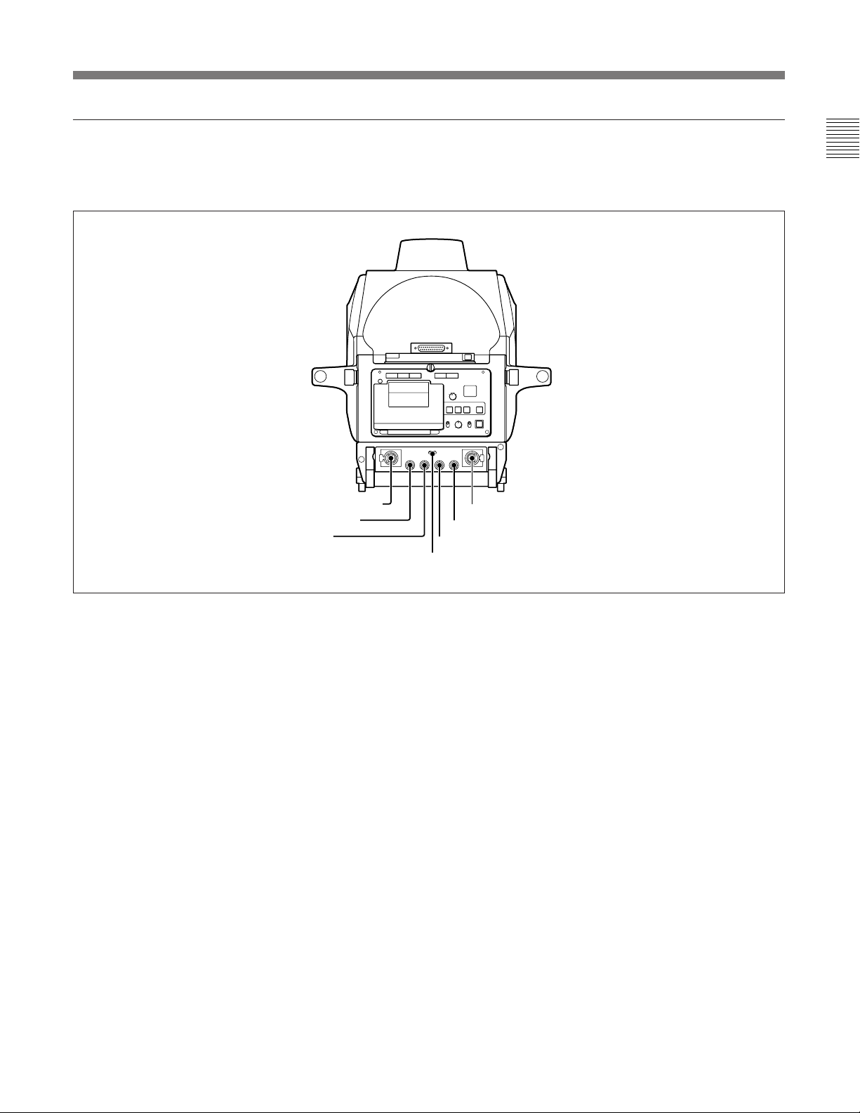
Rear panel of the BVP-900P
The functions of the switches and control numbered 1
through #º, see “Rear panel of the BVP-900”.
TRACKER ENG PROD PGM
INTERCOM INTERCOM
1
MIC
ENG
PROD
OFF
#¶INTERCOM connector
#•TRACKER control
#ªENG control
#¶ INTERCOM connector (XLR 5-pin)
•Connect an XLR 5-pin-type headset. The left
INTERCOM connector can be used for
communication even if the power to the camera is
turned OFF on the CCU-700AP. You can use the
right INTERCOM connector for an RTS intercom
system by installing an optional BKP-7913 RTS
Intercom System Kit, and two RTS Belt-pack can be
connected.
•You can monitor playback audio from the VTRs
when using the BVP-900P as a stand-alone unit.
#• TRACKER control
Adjusts the intercom level with the tracker.
#ª ENG (engineer line) control
Adjusts the intercom level of the engineer line.
#¶INTERCOM connector
$™PGM control
$¡PROD control
$ºMIC switch
$º MIC (microphone line select) switch
Selects the line to which the microphone of the headset
is to be connected.
ENG: For connecting to the engineer line.
OFF: For turning off the microphone.
PROD: For connecting to the producer line.
$¡ PROD (producer) control
Adjusts the intercom level of the producer line.
$™ PGM (program audio level) control
•Adjusts the output level of the program audio.
•This control adjusts the level of the playback audio
signals of the VTR when the BVP-900P is used as a
stand-alone camera.
13 (E)
 Loading...